sensitive process viscosity measurement - sofraser · sensitive process viscosity measurement at...
TRANSCRIPT


Sensitive process viscosity measurement at extremely high pressure for downhole applications
Wednesday, September 24th 2014
Corentin Thierry
Summary
• LWD Technology
• HPHT Requirements
• Viscometer/Densimeter for downhole applications – Design
– Specifications
– Pressure and temperature tests
– Mounting
• Wireline application
• Drilling Mud applications
• Multiple shear rate measurement

LWD/MWD • Logging While drilling : Set of
tools on the bottom hole assembly (BHA) used to retrieve information while drilling
• Measurement While Drilling : Part of the LWD tools used for positioning, direction and transmission of the information to the surface
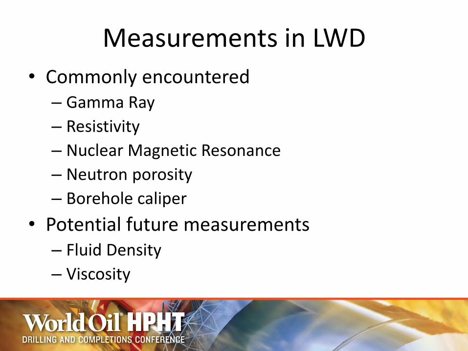
Measurements in LWD
• Commonly encountered – Gamma Ray
– Resistivity
– Nuclear Magnetic Resonance
– Neutron porosity
– Borehole caliper
• Potential future measurements – Fluid Density
– Viscosity
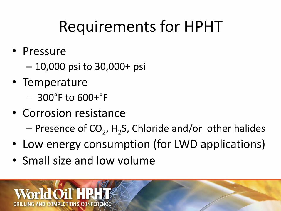
Requirements for HPHT
• Pressure – 10,000 psi to 30,000+ psi
• Temperature – 300°F to 600+°F
• Corrosion resistance – Presence of CO2, H2S, Chloride and/or other halides
• Low energy consumption (for LWD applications)
• Small size and low volume

New sensor for viscosity and density measurements in downhole
applications
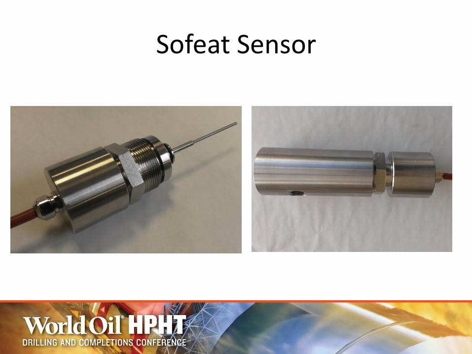
Sofeat Sensor
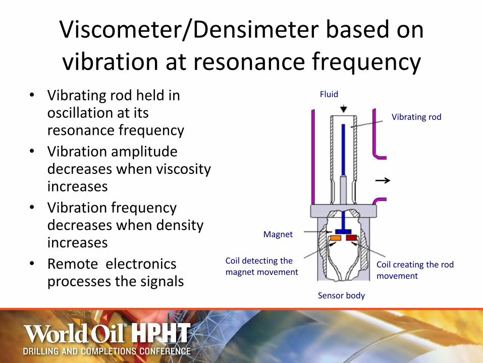
Viscometer/Densimeter based on vibration at resonance frequency
• Vibrating rod held in oscillation at its resonance frequency
• Vibration amplitude decreases when viscosity increases
• Vibration frequency decreases when density increases
• Remote electronics processes the signals
Sensor body
Coil detecting the magnet movement
Magnet
Coil creating the rod movement
Vibrating rod
Fluid

Coil detecting the magnet movement
Coil creating the rod movement
Amplitude of the rod (mV)
Product viscosity (cP)
•Resonance Freq •Amplitude changes

Sensor Specifications Already delivered by Sofraser
for downhole applications Possibilities Experimental
validation
Pressure Up to 20,000 psi at 70°F Up to 15,500 psi at 570°F
Up to 27,500 psi at 70°F Up to 21,000 psi at 570°F
Sensor temperature Up to 390 °F Up to 570°F
Size Ø60mm x 220mm TBD
Volume 0.6 L TBD
Weight 9 lbs(sensor + chamber) TBD
Material Corrosion resistant materials (eg : Stainless Steel, Hastelloy)
Viscosity Range 0 – 200 mPa.s Up to 1,000,000 mPa.s
Viscosity Accuracy 1% of reading 0.5% of reading
Density Range 5 to 13 ppg 0.8 to 16 ppg
Density Accuracy 0.4 ppg 0.08 ppg

Electronics Specifications
Already delivered by Sofraser for downhole applications
Temperature Up to 260°F
Size 100mm x 40mm x 10mm
Power supply 12 V
Power consomption < 1W
Communication RS 485, 250ms, 57600 baud
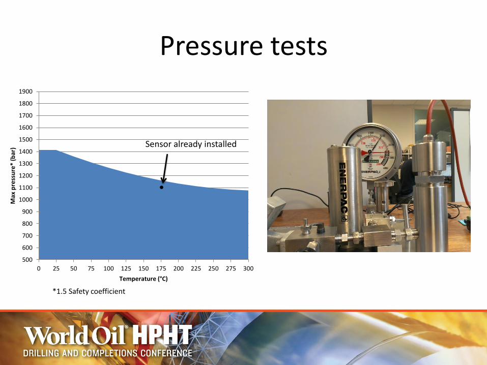
Pressure tests
500
600
700
800
900
1000
1100
1200
1300
1400
1500
1600
1700
1800
1900
0 25 50 75 100 125 150 175 200 225 250 275 300
Max
pre
ssu
re*
(bar
)
Temperature (°C)
Sensor already installed
*1.5 Safety coefficient
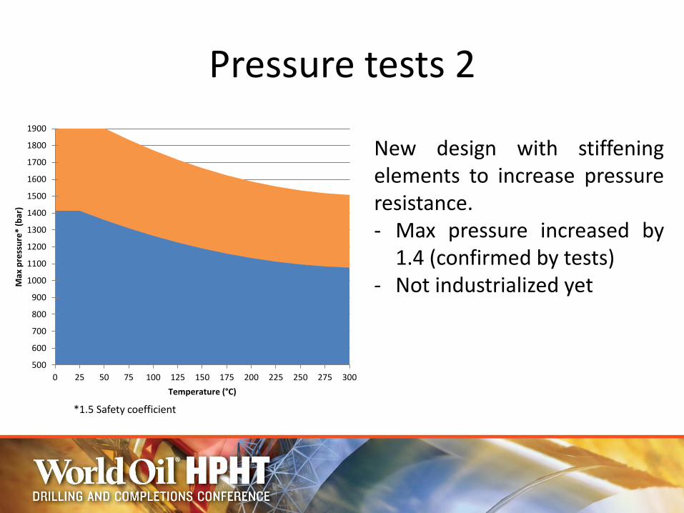
Pressure tests 2
500
600
700
800
900
1000
1100
1200
1300
1400
1500
1600
1700
1800
1900
0 25 50 75 100 125 150 175 200 225 250 275 300
Max
pre
ssu
re*
(bar
)
Temperature (°C)
New design with stiffening elements to increase pressure resistance. - Max pressure increased by
1.4 (confirmed by tests) - Not industrialized yet
*1.5 Safety coefficient

Temperature tests on electronic board
0
500
1000
1500
2000
2500
3000
3500
4000
0 5 10 15 20 25 30 35 400
500
1000
1500
2000
2500
3000
3500
4000
0 20 40 60 80 100 120 140
Amplitude vs time Amplitude vs température (°C)
125°C
100°C 100°C
80°C 80°C
50°C 50°C
Thermal drift compensated by quadratic equation
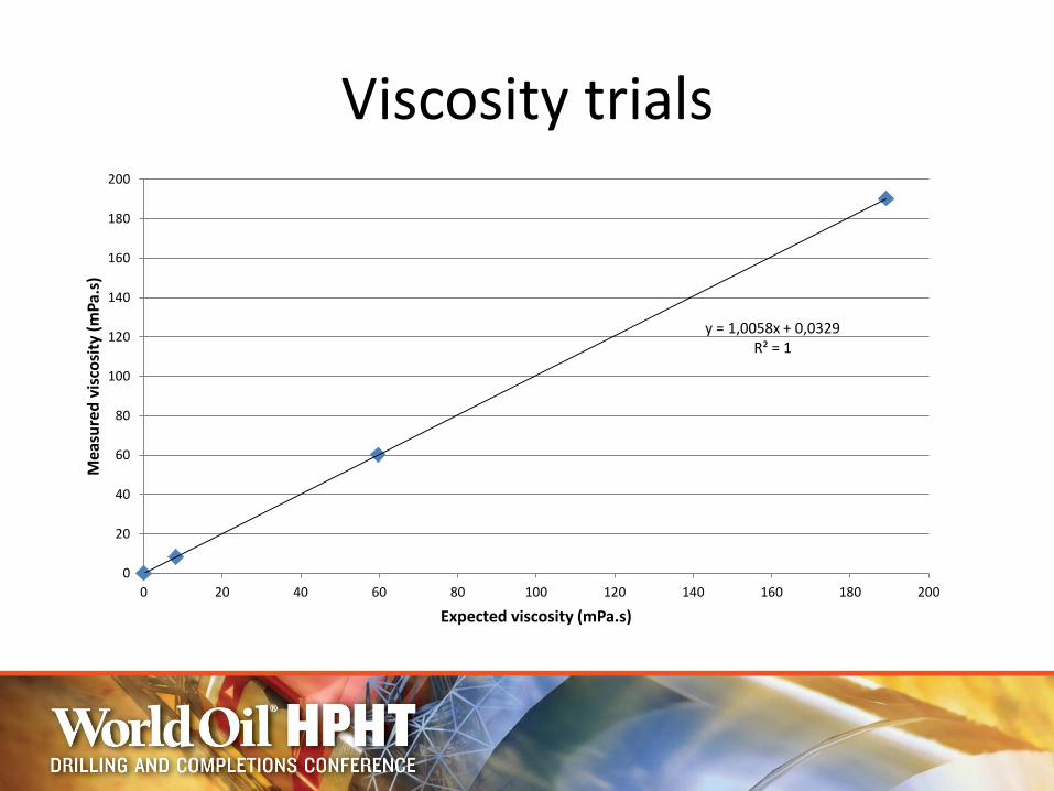
Viscosity trials
y = 1,0058x + 0,0329 R² = 1
0
20
40
60
80
100
120
140
160
180
200
0 20 40 60 80 100 120 140 160 180 200
Mea
sure
d v
isco
sity
(m
Pa.
s)
Expected viscosity (mPa.s)

Mounting
• Flow through cell mounting
• Sensor screwed onto measuring cell using threading
• Electronics installed remotely in the same pipe
• Sensor and electronics installed in WL/BHA

Applications
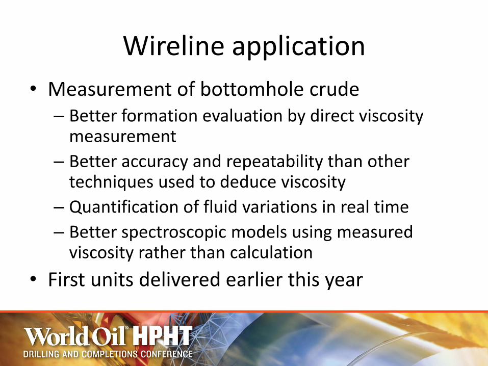
Wireline application
• Measurement of bottomhole crude – Better formation evaluation by direct viscosity
measurement
– Better accuracy and repeatability than other techniques used to deduce viscosity
– Quantification of fluid variations in real time
– Better spectroscopic models using measured viscosity rather than calculation
• First units delivered earlier this year

Drilling mud measurements
• Mud weight measurement at bottomhole and/or surface
• Viscosity at multiple shear rate for modeling flow curve – Reduce the amount of laboratory tests
– Possibility for downhole and/or surface measurement
• Measurement on various mud types (Water based, Emulsions, Oil based)
• Continuous measurement – Information between 2 lab tests
– Trending for quick adjustments when needed

Viscosity measurement at multiple shear rate
• Use of inline viscometers to monitor Plastic Viscosity and Yield Point in real time – 2 sensors measuring at 500 s-1 and 1000 s-1
• Correlation between lab and viscometers to evaluate further mud properties – Possibility to measure from 300 s-1
to 1000+ s-1 using vibrating technology
• Solution currently under development
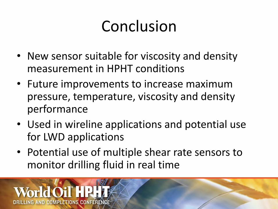
Conclusion
• New sensor suitable for viscosity and density measurement in HPHT conditions
• Future improvements to increase maximum pressure, temperature, viscosity and density performance
• Used in wireline applications and potential use for LWD applications
• Potential use of multiple shear rate sensors to monitor drilling fluid in real time

Thank you
Mr. Corentin THIERRY - MSc Applications Specialist - Sofraser
19407 Oil Center Boulevard, Houston, Texas, 77073 Phone: 281-214-8295
Cell: 281-740-7257 Fax: 281-591-0052
Email: [email protected] Web: www.sofraser.com