sensor3® cem3 user manual - christie lites the largest ... remove face panel. eject leds identify...
TRANSCRIPT

Part Number: 7140M1200-1.6.1 Rev: A
Released: 2017-08
Sensor3CEM3
User Manual
Version 1.6.1

ETC® and Sensor® are e i ther reg is tered t rademarks or t rademarks of E lec t ron ic Theatre Contro ls ,
Inc . in the United States and other countr ies .
A l l other t rademarks , both marked and not marked, are the property of the i r respect ive owners .
ETC intends th i s document , whether pr inted or e lect ron ic , to be prov ided in i t s ent i re ty .Th i s
product i s intended for profess iona l use on ly . Read th i s ent i re document before us ing th i s product .

Table of Contents i
Table of Contents
Introduction . . . . . . . . . . . . . . . . . . . . . . . . .1
Using this Manual. . . . . . . . . . . . . . . . . . . . . . . . . . . . . .1Text Conventions . . . . . . . . . . . . . . . . . . . . . . . . . . . . . . . . . . . .1
Help from ETC Technical Services . . . . . . . . . . . . . . . . .2
Chapter 1 Getting Started . . . . . . . . . . . . . . . . . . . . . .3
The User Interface . . . . . . . . . . . . . . . . . . . . . . . . . . . . .3CEM3 Face Panel. . . . . . . . . . . . . . . . . . . . . . . . . . . . . . . . . . . . .3Navigation. . . . . . . . . . . . . . . . . . . . . . . . . . . . . . . . . . . . . . . . . .3
Performing a Quick Setup . . . . . . . . . . . . . . . . . . . . . . .4Other Setup Functions . . . . . . . . . . . . . . . . . . . . . . . . . . . . . . . .5
Chapter 2 System Reference. . . . . . . . . . . . . . . . . . . . .6
Important Concepts . . . . . . . . . . . . . . . . . . . . . . . . . . . .6Advanced Features (AF) . . . . . . . . . . . . . . . . . . . . . . . . . . . . . . .6Circuit . . . . . . . . . . . . . . . . . . . . . . . . . . . . . . . . . . . . . . . . . . . . .6Configuration . . . . . . . . . . . . . . . . . . . . . . . . . . . . . . . . . . . . . . .6Dimmer Doubling (UL/ 120V 60Hz Systems Only). . . . . . . . . . .6Latch-Lock . . . . . . . . . . . . . . . . . . . . . . . . . . . . . . . . . . . . . . . . . .7Lug. . . . . . . . . . . . . . . . . . . . . . . . . . . . . . . . . . . . . . . . . . . . . . . .7Panic . . . . . . . . . . . . . . . . . . . . . . . . . . . . . . . . . . . . . . . . . . . . . .8Patch . . . . . . . . . . . . . . . . . . . . . . . . . . . . . . . . . . . . . . . . . . . . . .8Preset Functions . . . . . . . . . . . . . . . . . . . . . . . . . . . . . . . . . . . . .9Redundant Tracking (ESR and FDX Racks Only) . . . . . . . . . . .10Variable Speed Fan. . . . . . . . . . . . . . . . . . . . . . . . . . . . . . . . . .10
Menu Structure. . . . . . . . . . . . . . . . . . . . . . . . . . . . . . .10Test . . . . . . . . . . . . . . . . . . . . . . . . . . . . . . . . . . . . . . . . . . . . . .11About . . . . . . . . . . . . . . . . . . . . . . . . . . . . . . . . . . . . . . . . . . . .12Setup . . . . . . . . . . . . . . . . . . . . . . . . . . . . . . . . . . . . . . . . . . . . .13
UI Preferences . . . . . . . . . . . . . . . . . . . . . . . . . . . . . . . .14
Dimmer Property Definitions. . . . . . . . . . . . . . . . . . . .15
Rack Property Definitions . . . . . . . . . . . . . . . . . . . . . .18

ii CEM3 User Manual
Dimmer Curves . . . . . . . . . . . . . . . . . . . . . . . . . . . . . . .19Linear. . . . . . . . . . . . . . . . . . . . . . . . . . . . . . . . . . . . . . . . . . . . .19Modified Linear (Mod-Linear) . . . . . . . . . . . . . . . . . . . . . . . . .19Square Law (Square). . . . . . . . . . . . . . . . . . . . . . . . . . . . . . . . .20Modified Square Law (Mod-Square) . . . . . . . . . . . . . . . . . . . .20Sensor 2.0 . . . . . . . . . . . . . . . . . . . . . . . . . . . . . . . . . . . . . . . . .21Stage 1. . . . . . . . . . . . . . . . . . . . . . . . . . . . . . . . . . . . . . . . . . . .21Stage 2. . . . . . . . . . . . . . . . . . . . . . . . . . . . . . . . . . . . . . . . . . . .22Fluro1 . . . . . . . . . . . . . . . . . . . . . . . . . . . . . . . . . . . . . . . . . . . .22Fluro 2 . . . . . . . . . . . . . . . . . . . . . . . . . . . . . . . . . . . . . . . . . . . .22ANDI . . . . . . . . . . . . . . . . . . . . . . . . . . . . . . . . . . . . . . . . . . . . .23VIP 90. . . . . . . . . . . . . . . . . . . . . . . . . . . . . . . . . . . . . . . . . . . . .23Custom . . . . . . . . . . . . . . . . . . . . . . . . . . . . . . . . . . . . . . . . . . .23
Dimmer Output Diagram . . . . . . . . . . . . . . . . . . . . . . .24
Chapter 3 Common Tasks . . . . . . . . . . . . . . . . . . . . . .25
Replacing the CEM3 Processor. . . . . . . . . . . . . . . . . . .25Configuration Selection . . . . . . . . . . . . . . . . . . . . . . . . . . . . . .25Incorrect Version. . . . . . . . . . . . . . . . . . . . . . . . . . . . . . . . . . . .25
Recording and Playing Presets. . . . . . . . . . . . . . . . . . .25Preset Menu . . . . . . . . . . . . . . . . . . . . . . . . . . . . . . . . . . . . . . .26
Recording and Playing Sequences . . . . . . . . . . . . . . . .27Sequence Menu . . . . . . . . . . . . . . . . . . . . . . . . . . . . . . . . . . . .27
Saving or Uploading Files and Firmware . . . . . . . . . .28Saving Configurations . . . . . . . . . . . . . . . . . . . . . . . . . . . . . . .28Loading Configurations . . . . . . . . . . . . . . . . . . . . . . . . . . . . . .28Loading CEM3 Software. . . . . . . . . . . . . . . . . . . . . . . . . . . . . .29
Setting Up Panic . . . . . . . . . . . . . . . . . . . . . . . . . . . . . .30
Patching . . . . . . . . . . . . . . . . . . . . . . . . . . . . . . . . . . . .32Automatic Patching . . . . . . . . . . . . . . . . . . . . . . . . . . . . . . . . .32Manual Patching. . . . . . . . . . . . . . . . . . . . . . . . . . . . . . . . . . . .32
Setting Data Loss Behavior . . . . . . . . . . . . . . . . . . . . .33
Setting Up CEM3 on the Network . . . . . . . . . . . . . . . .33Network Setup for Redundant Tracking Racks. . . . . . . . . . . .34Working with Net3 Conductor Over FTP . . . . . . . . . . . . . . . .34
Setting Rack DIP Switches and Termination . . . . . . . .34DIP Switch Settings . . . . . . . . . . . . . . . . . . . . . . . . . . . . . . . . . .35DMX Termination Switches . . . . . . . . . . . . . . . . . . . . . . . . . . .35
Maintaining and Cleaning the Rack . . . . . . . . . . . . . .36Cleaning Rack Air Filters . . . . . . . . . . . . . . . . . . . . . . . . . . . . .36Vacuuming Dimmer Modules . . . . . . . . . . . . . . . . . . . . . . . . .37
Replacing AF Cards . . . . . . . . . . . . . . . . . . . . . . . . . . . .38
Restoring Rack Defaults . . . . . . . . . . . . . . . . . . . . . . . .39

Table of Contents iii
Chapter 4 Web Access and Mobile App . . . . . . . . . .40
Using the CEM3 Web Interface . . . . . . . . . . . . . . . . . .40System . . . . . . . . . . . . . . . . . . . . . . . . . . . . . . . . . . . . . . . . . . . .40Dimmers . . . . . . . . . . . . . . . . . . . . . . . . . . . . . . . . . . . . . . . . . .40Set Levels. . . . . . . . . . . . . . . . . . . . . . . . . . . . . . . . . . . . . . . . . .41Setup . . . . . . . . . . . . . . . . . . . . . . . . . . . . . . . . . . . . . . . . . . . . .41Presets and Sequences . . . . . . . . . . . . . . . . . . . . . . . . . . . . . . .41Files . . . . . . . . . . . . . . . . . . . . . . . . . . . . . . . . . . . . . . . . . . . . . .42
Using the Sensor3 ThruPower System Reporter . . . . .42
Appendix A CEM3 Menu Flow Chart . . . . . . . . . . . . . .44
Boot Screen . . . . . . . . . . . . . . . . . . . . . . . . . . . . . . . . . .45Normal Operation . . . . . . . . . . . . . . . . . . . . . . . . . . . . . . . . . .45Rack Type Mismatch . . . . . . . . . . . . . . . . . . . . . . . . . . . . . . . . .45Configuration File Conflict. . . . . . . . . . . . . . . . . . . . . . . . . . . .45Backplane Mismatch. . . . . . . . . . . . . . . . . . . . . . . . . . . . . . . . .45
Home Screen . . . . . . . . . . . . . . . . . . . . . . . . . . . . . . . . .46Normal Operation . . . . . . . . . . . . . . . . . . . . . . . . . . . . . . . . . .46Panic . . . . . . . . . . . . . . . . . . . . . . . . . . . . . . . . . . . . . . . . . . . . .46AF Card Upgrade . . . . . . . . . . . . . . . . . . . . . . . . . . . . . . . . . . .46Battery Backup or RideThru Active . . . . . . . . . . . . . . . . . . . . .46Redundant Tracking . . . . . . . . . . . . . . . . . . . . . . . . . . . . . . . . .46
Quick Setup and Info . . . . . . . . . . . . . . . . . . . . . . . . . .47
Test . . . . . . . . . . . . . . . . . . . . . . . . . . . . . . . . . . . . . . . .48
About . . . . . . . . . . . . . . . . . . . . . . . . . . . . . . . . . . . . . .50
Setup . . . . . . . . . . . . . . . . . . . . . . . . . . . . . . . . . . . . . . .51
Appendix B Error Messages. . . . . . . . . . . . . . . . . . . . . .56
Appendix C Redundant Tracking Systems . . . . . . . . . .59
Redundant Tracking Switch . . . . . . . . . . . . . . . . . . . . .59
Automatic Control . . . . . . . . . . . . . . . . . . . . . . . . . . . .59Loss of network . . . . . . . . . . . . . . . . . . . . . . . . . . . . . . . . . . . .60Loss of DMX . . . . . . . . . . . . . . . . . . . . . . . . . . . . . . . . . . . . . . .60Power errors . . . . . . . . . . . . . . . . . . . . . . . . . . . . . . . . . . . . . . .60Total processor loss. . . . . . . . . . . . . . . . . . . . . . . . . . . . . . . . . .60
Display Status . . . . . . . . . . . . . . . . . . . . . . . . . . . . . . . .60
Configuration Management in Redundant Tracking Systems . . . . . . . . . . . . . . . . . . . . . . . . . . . . . . . . . . . . .61
Firmware Upgrades in Redundant Tracking Systems .61

iv CEM3 User Manual
Appendix D FDX 3000 Dimmer Racks . . . . . . . . . . . . . .62
Hardware . . . . . . . . . . . . . . . . . . . . . . . . . . . . . . . . . . .62Front Panel . . . . . . . . . . . . . . . . . . . . . . . . . . . . . . . . . . . . . . . .62Rear Panel . . . . . . . . . . . . . . . . . . . . . . . . . . . . . . . . . . . . . . . . .63
Regulatory Information . . . . . . . . . . . . . . . . . . . . . . . .64
Initial Setup. . . . . . . . . . . . . . . . . . . . . . . . . . . . . . . . . .64Module Count. . . . . . . . . . . . . . . . . . . . . . . . . . . . . . . . . . . . . .64
Module Types . . . . . . . . . . . . . . . . . . . . . . . . . . . . . . . .64
Advanced Features in FDX . . . . . . . . . . . . . . . . . . . . . .64Feedback Modes and Module Types . . . . . . . . . . . . . . . . . . . .65Roasting Short Protection . . . . . . . . . . . . . . . . . . . . . . . . . . . .65
FDX2000 vs. FDX3000 Dimmer Curve Comparison . . .66

Introduction 1
Introduction
Welcome to your new CEM3 Power Control system.
This manual is designed to introduce you to the CEM3 user interface and the primary features and functions available to you in the setup and use of your CEM3 power control system.
Using this Manual
The following graphics and conventions are used throughout this manual to convey important information.
Text Conventions• Bold is used to indicate something in the CEM3 user interface, such as a parameter or button.
• [Brackets] are used to indicate a tactile button on the face of the CEM3 (such as [Setup], [Test],
and [Enter]).
Please email comments about this manual to: [email protected].
Note: Notes are helpful hints and information that is supplemental to the main text.
CAUTION: A Caution statement indicates situations where there may be undefined or unwanted consequences of an action, potential for data loss or an equipment problem.
WARNING: A Warning statement indicates situations where damage may occur, people may be harmed, or there are serious or dangerous consequences of an action.
WARNING: RISK OF ELECTRIC SHOCK! This warning statement indicates situations where there is a risk of electric shock.

2 CEM3 User Manual
Help from ETC Technical Services
If you are having difficulties, your most convenient resources are the references given in this user manual. To search more widely, try the ETC website at etcconnect.com or the Dimming and Networking Systems page at community.etcconnect.com.
If none of these resources are sufficient, contact ETC Technical Services directly at one of the offices identified below. Emergency service is available from all ETC offices outside of normal business hours.
When calling for help, please have the following information handy:
• Product model and serial number (located on the bottom of the CEM3)
• Installation type
• Other components in your system (Unison®, other consoles, etc.)
Americas United KingdomETC, Inc. ETC Ltd
Technical Services Department Technical Services Department
3031 Pleasant View Road 26-28 Victoria Industrial Estate
Middleton, WI 53562 Victoria Road,
800-775-4382 (USA, toll-free) London W3 6UU England
+1-608 831-4116 +44 (0)20 8896 1000
[email protected] [email protected]
Asia GermanyETC Asia ETC GmbH
Technical Services Department Technical Services Department
Room 1801, 18/F Ohmstrasse 3
Tower 1, Phase 1 Enterprise Square 83607 Holzkirchen, Germany
9 Sheung Yuet Road +49 (80 24) 47 00-0
Kowloon Bay, Kowloon, Hong Kong [email protected]
+852 2799 1220

Getting Started 3
Chapter 1Getting Started
The User InterfaceThis section explains the physical features of the hardware interface and their general functionality
with the software.
CEM3 Face Panel
The diagram below shows the components of the hardware interface. These terms are used
throughout this manual.
Navigation
Scroll Wheel
Use the scroll wheel and up/down arrows to move the selection cursor on any menu screen until the
desired item is highlighted. Menus that do not fit on one screen will have a scroll bar on the right side
of the display window, and additional menu options can be accessed with the scroll wheel. You can
also tap the top or bottom of the scroll wheel to move the display cursor up or down.
The scroll wheel also lets you scroll through number fields (such as circuit number) or through the
available options for a selected item (such as Module Type).
The center button of the scroll wheel functions as [Enter]. Press [Enter] to select the highlighted item on
the display window or to commit entered data.
Keypad
Use keypad to enter values for any value fields in the display window. When setting levels you can
select individual dimmers or ranges of dimmers using the [and] and [thru] buttons.
Both the center button of the scroll wheel and the bottom right keypad button function as [Enter].
Press [Enter] to select the highlighted item on the display window or to commit entered data.
CAUTION: Power down the rack before removing the CEM3 face panel.
Eject: Pull both levers forward from the top edge. Grasp and pull to remove face panel.
Eject
LEDs identify current states of:
Power DMX Ports Network PanicReset
Net3 Ethernet
USBLoad Software and configurations
Display window
NavigationButtons
Scroll wheel
Keypad

4 CEM3 User Manual
Navigation Buttons
The navigation buttons ([Test], [About], [Setup]) and the [Back] button are used to navigate menus in
the display window (see Menu Structure on page 10). Press [Back] to return to the previous screen on
any menu.
Performing a Quick SetupQuick Setup is used to set up your rack using a minimum amount of data to achieve a basic
configuration.
You can begin a Quick Setup by selecting Quick Setup from the main screen or by navigating to
[Setup]>Quick Setup>[Enter].
From this screen you can use the CEM3 interface to enter data in up to four screens to quickly establish
your rack configuration: Module, Circuit, Dimmer Double, and Patching (see below for screen
descriptions).
Once you have entered data in the screens, select OK and press [Enter] to save the setup changes.
Module
The current Rack Type is listed. To change the module type select Module. Select a module type and
model from the list, then select Next.
Circuit
Set Numbering to either Renumbering or Unchanged to indicate whether to renumber the rack. If you
select Renumbering, set these two additional parameters:
• Set the Starting At value to the number for the first circuit in the rack. If this is your first or only
rack, this number is typically 1. If this rack is one of many in your system, this number typically
continues the numbering sequence from the previous rack. Default is 1.
• Set the Balance type: Straight, 1-Phase, or 3-Phase. The CEM3 processor defaults to the balance
type that is appropriate for the detected power source, but you can change this value if desired.
- Straight results in circuit numbering that will proceed sequentially straight through the entire
rack.
- 1-Phase or 3-Phase results in circuit numbering that distributes the circuits evenly across the
different power phases so that neighboring circuits do not place an uneven load on any phase.
Note: Prior to performing a Quick Setup, make sure that your rack DIP switch settings are set appropriately for your rack type. See Setting Rack DIP Switches and Termination on page 34.
CAUTION: Quick Setup will overwrite some of the data in your rack. Only perform a Quick Setup when you want to reconfigure your system or are instructed to do so by ETC Technical Services.

Getting Started 5
These tables compare the circuit numbering of an SR3-6 filled with D20 modules when set to Straight
numbering, 3-Phase numbering, or 1-Phase numbering:
Dimmer Double
Choose between Yes and No to activate or deactivate dimmer doubling for the rack. Default is No. See
Dimmer Doubling (UL/ 120V 60Hz Systems Only) on page 6.
You can also set a DMX Offset (default = 256) or sACN Offset (default =10000), which determines the
start address of the B side of the dimmer doubled dimmers.
Patch
Select an automatic patching method to patch the entire rack sequentially.
There are three automatic patching methods:
• Simple: This patching method specifies the same starting address for all three data ports (DMX
A, DMX B, and sACN) at once. Enter the starting address for the patch. If the patch count exceeds
512, the patch will “wrap” and start numbering again at 1.
• Independent: This method allows you to specify different starting addresses for each data port in
the patch (DMX A, DMX B, and sACN). Select a data port and assign the desired starting address
for the rack. If the rack count then exceeds 512 (for DMX ports) the remainder of circuits in the
rack will be patched to zero for that DMX port.
• Universe Split: This patching method should be used when a DMX universe will end midway
through the rack’s patch. Enter the starting address for the patch. If the patch sequence exceeds
512 (256 if dimmer doubling is enabled) DMX A will patch the rest of the circuits to 0 and DMX B
will restart the patch addresses at 1 for those remaining circuits.
Other Setup Functions
Once you have completed the quick setup, you may wish to proceed to these other common setup
tasks:
• Setting the module type in Circuit Assignment on page 13
• Setting Up Panic on page 30
• Setting Up CEM3 on the Network on page 33
Phase
SR3-6 Straight
Circuit Numbering
SR3-63-Phase
Circuit NumberingPhase
SR3-61-Phase
Circuit Numbering
A
1 1
A
1
2 2 2
3 7 5
4 8 6
B
5 3 9
6 4 10
7 9
B
3
8 10 4
C
9 5 7
10 6 8
11 11 11
12 12 12
Note: Automatic patching is only available for racks with one space. For racks with more than one assigned space, see Patching on page 32.

6 CEM3 User Manual
Chapter 2System Reference
This chapter includes the general concepts behind the features of your CEM3, the general menu
structure of the software, definitions of all dimmer properties, and illustrations of the various dimmer
curves available in your system.
Important ConceptsThis section introduces some of the primary concepts. Topics are listed alphabetically.
Advanced Features (AF)
Advanced Features (AF) allow you to receive feedback from your dimmer modules about their current
state, including the amount of current being drawn on each circuit, whether the module is installed or
not, and whether the circuit breaker on the module has tripped. This information is available both at
the front panel of the rack and at remote devices, including ETC Eos® and Cobalt® control systems and
other ACN-capable devices.
Advanced Features also allow you to monitor circuit loads by recording and running a rig check (see Rig Check on page 10).
In order to use Advanced Features, you need AF-capable modules (modules with AF in the module
name, such as D20AF or ED15AF) and AF cards installed in the rack.
Circuit
A circuit is a user assignable number between 1 and 99999. The circuit is the reference number for that
dimmer in the rack. Circuit numbers must be unique per space; it is possible to have multiple circuits of
the same number, but they must be in different spaces.
Configuration
The rack configuration is a collection of all of the data stored about the rack and all of its circuits. The
configuration is stored automatically in the CEM3 whenever you make a change (for example,
changing a circuit from switched to dimmed).
The configuration of any rack is automatically stored on both the CEM3 module and the CEM3
backplane. Therefore, you can remove a CEM3, replace it with a new, unconfigured CEM3, and the
configuration from the backplane will be loaded to the new CEM3.
You can save and load rack configurations by connecting a USB removable media device to the USB
port on the front of the module, by connecting to a computer on the network (using the CEM3 web
interface), or by connecting to an FTP server. Saving and loading are performed from the File
Operations menu. See Saving or Uploading Files and Firmware on page 28.
Dimmer Doubling (UL/ 120V 60Hz Systems Only)
ETC’s Dimmer Doubler™ technology allows you to double the number of controllable circuits in your
system without adding dimmer modules or running additional cable. The key to this feature is the
Dimmer Doubler two-fer.
The Dimmer Doubler two-fer is installed between a Sensor dimmer module and two ETC Source Four
77-volt fixtures. It splits the output of a single dimmer into two separately controlled outputs.

System Reference 7
Latch-Lock
Latch-Lock is a control mode available to any dimmer circuit (see Control on page 15). Similar to
switched mode, Latch-Lock features an additional safeguard so that circuits cannot be turned on or off
as easily. The circuit only turns on when a defined control level range is held for a specified amount of
time, and only turns off when a different control level range is held for another amount of time.
Latch-Lock is useful for avoiding accidental dowsing of arc lamps during shows (often caused by
running the grandmaster down). By requiring a level range and time, most master fades will not hover
in a given range for long enough to trigger on or off.
The level ranges and times can be edited on a per dimmer basis (see Dimmer Property Definitions on
page 15). On and Off level ranges may not overlap.
Lug
“Lug” refers to a physical position in the rack. Lugs are always numbered counting downwards from
the top of the rack, starting at 1. Some modules may take up multiple lug positions in the rack.
Level
Time
Latch-Lock on range
Latch-Lock On Time
Latch-Lock off range
Latch-Lock Off Time
During this time interval the control source can go to any level and the circuit will stay on (relay closed) as long as the control source level does not stay in the Latch-Lock off range longer than the Latch-Lock off time value.
Control Level
relay open(circuit off)
relay closed(circuit on)
Timerelay closes(circuit turns on)
relay opens(circuit turns off)
Diagram of How Latch-Lock is Applied to a Circuit

8 CEM3 User Manual
Panic
CEM3 offers a panic capability that complies with the UL 924 standard.
When a properly connected and enabled CEM3 has a panic “look” stored, it will automatically play the
recorded look when it receives a signal over the panic circuit.
Panic can be enabled when a maintained (normally open or normally closed) contact closure is properly
wired to the backplane. For more information, see the data termination guide or installation guide that
was supplied with the rack.
For information on how to configure panic on your CEM3, see Setting Up Panic on page 30.
Patch
Patching governs the relationship between control input sources (DMX A, DMX B, and sACN) and the
control of circuits in the rack. This relationship can be edited to match the needs of your control
sources and rack constraints. For information on patching, see Patching on page 32.
Note: To configure panic mode through an electrical override without using the CEM3 module software, order the Hardwired Panic Accessory (7140K1002). Contact your local dealer for more information.

System Reference 9
Preset Functions
CEM3 supports a built-in preset control system allowing the recording and playback of preset looks.
Once recorded, preset looks can be played back either from the CEM3 face panel, connected Echo
preset stations, or the web interface. For more information on recording and playing back presets see
Recording and Playing Presets on page 25.
CEM3 allows the circuits within the rack to be divided up into spaces (performed in Circuit Assignment on page 13) with up to 64 presets available per space. Each space can only have one active preset at a
time.
CEM3 includes default presets that include all circuits in the space. The default presets for any space
start with level at 100% and then cycle through 75%, 50%, 25%, 100% and so on.
The built-in EchoConnect® power supply on a Sensor3 rack is limited to powering 6 racks or panels and
6 stations. However, you can expand the system with external equipment. For more information about
Echo systems, visit etcconnect.com.
When you activate a preset, this action is propagated across the Net3 network. For example, if you
activate a given preset for space 1, all CEM3 modules on the network will activate that preset for
space 1.
CAUTION: Do not activate station power on more than one CEM3 on the same EchoConnect® bus. Doing so may cause undesirable station function.
EchoConnect® - Belden 8471 + (1) 14 AWG ESD Ground Wire

10 CEM3 User Manual
Rig Check
In Sensor3 racks with Advanced Features (see Advanced Features (AF) on page 6) you can record a
special preset called Rig Check, which includes both circuit levels and the amount of load (current)
expected on each circuit.
Once recorded, the Rig Check can be played back, either from the CEM3 face panel or remotely, and
the CEM3 will post load high, load low, or no load messages based on how the load of the circuit has
changed since you recorded the Rig Check preset. These messages will be available on the CEM3
display or on a connected console that monitors AF feedback.
You can record, run, and clear a rig check on the Test menu (see Test on page 11).
Spaces
Spaces are logical divisions within a system (such as different rooms) that isolate station control (preset
and sequence control) to the defined group of controllable outputs in that division. CEM3 supports
separation of its controllable circuits into spaces.
Station Functions
Presets can be played back from preset stations in the system.
• Press a preset station button to activate a preset.
• Press it again to deactivate the preset.
• Stations can be configured with an Off button. This option is performed at the station and should
only be done by a qualified technician.
• The group of presets controlled by any station can be altered at the station. This should only be
done by a qualified technician.
For more information see the Echo Preset Station Installation Guide available at etcconnect.com.
Redundant Tracking (ESR and FDX Racks Only)
Redundant tracking provides extra security in the event of system failure, allowing a secondary CEM3
control module to immediately take control of the rack. For more information, see Redundant Tracking Systems on page 59.
Variable Speed Fan
The variable speed fan reduces the amount of noise generated by a Sensor3 rack, specifically when the
rack is lightly loaded. The variable speed fan is supported in the following product models:
• ESR24
• ESR36
• ESR48
The fan operates at two speeds: High and Low. The fan uses the AF Features of the rack to run more
slowly when less current is being drawn.
Menu StructureThis section describes the menu structure of the software. Press the desired button to access the menu
items below. Use the standard navigation method to select and enter options in the menus (see
Navigation on page 3).

System Reference 11
Test Field Description
Set Circuits
Set levels for chosen circuits in a space. If necessary, press [Back] to clear the
command line during any of the following steps.
1: Use the keypad to enter a circuit number between 1 and 99999.
2: Press [and] to enter multiple circuits or press [thru] to enter a range of
circuits.
• Press [Last/A] or [Next/B] on the keypad to set a level for the A or B
side of dimmer doubled circuits. See example below.
3: Press [at] or [Enter]. The command line ends with "at".
4: Use the keypad or scroll wheel to enter a level if desired.
5: Press [Enter]. The selected circuits will be set to the specified level or
released if you did not enter a level. The command line ends with "*".
6: If you selected a single circuit, press [Next] or [Last] on the keypad to
increment or decrement the circuit number to set the level of another
circuit, if desired.
Dimmer CheckQuickly run through all circuits in a space to test their output at a given
percentage.
Release Set Lvls Release any active levels for a given space at once.
Presets Record or play back presets. See Recording and Playing Presets on page 25.
SequencesRecord or play back sequences. See Recording and Playing Sequences on
page 27.
Release All ArchRelease all architectural control such as presets, sequences, and set zone
levels.
Record Rig Check
Record a rig check preset to facilitate AF reporting. Rig Check features are
only available if the rack property AF Enabled is set to Yes. See Rig Check
on page 10, Advanced Features (AF) on page 6, and Rack Property Definitions on page 18 for more information.
Run Rig CheckRun a rig check preset. You will be notified of any load inconsistencies
found during the rig check.
Clear Rig Check Clear the recorded rig check from all racks for a given space.
Example: Setting the A and B sides of one dimmer doubled circuit at a time is straightforward using the A and B keys. It is possible to set ranges of dimmer doubled circuits. The following are valid examples:
A side only
• 1 at 100 or 1A at 100 sets 1A to full
• 1 thru 6 at 100, 1 thru 6A at 100, 1A thru 6 at 100, or 1A thru 6A at 100 sets the A
sides of 1 through 6 at full
B side only
• 1B at 100 sets 1B to full
• 1B thru 6B at 100 sets B sides of 1 through 6 at full
Some A and some B sides
• 1 thru 6B at 100 or 1A thru 6B at 100 sets the A and B sides of 1 through 6 to full
• 1B thru 6 at 100 or 1B thru 6A at 100 sets 1B and the A sides of 2 through 6 to full

12 CEM3 User Manual
AboutField Description
DimmersView all properties for any circuit in a space or in any rack on the network.
See Dimmer Property Definitions on page 15.
Rack
View all properties for the host Sensor rack. See Rack Property Definitions on page 18.
• Status: displays "Rack OK" or "Errors Exist"
• Panic State: displays "Ready" when not in a panic condition and
"Active" when in a panic condition.
ErrorsView any current errors or other status messages. See Error Messages on
page 56.
Source Info
View the current control source (Highest-Takes-Precedence or “HTP”) and
related output level being received by all dimmers in a space.
• "DMXA" is DMX Port A
• "DMXB" is DMX Port B
• "sACN" is Streaming sACN
• "AF" means Advanced Features is using the dimmer for load
recording
• "SetLevels" means Set Levels or Dimmer Check is in use on
the dimmer
• "ACNDirect" is ACN Direct Control
• "Preset" followed by a number means a preset is running on
the dimmer
• "Panic" means the panic settings are in effect
• "--" means no control of the dimmer
About CEM3Displays the current software version on your CEM3 processor. You can
also save a copy of the CEM3 User Guide to a USB drive.

System Reference 13
Setup
Commonly used features found here include:
• changing dimmer, rack, and network settings
• enabling control ports
• changing operating mode
• upgrading software or backing up the rack configuration
• changing curve and firing mode
Field Description
DimmersView and adjust the settings for any circuit in any rack connected to the
network. See Dimmer Property Definitions on page 15.
RackView and adjust the settings for the host Sensor3 rack. See Rack Property Definitions on page 18.
Circuit Assignment
Assign the space, circuit number, and module type for any circuit slot in the
rack. You can auto assign or manually edit the options for any circuit.
For single and half-density modules such as the D20F, select Edit Circuit
Layout to adjust circuit numbering before you perform final patch updates.
PatchingEdit the patch and functionality for any port (DMX or sACN). See Patching
on page 32.
NetworkSet up and edit network properties for the CEM3. See Setting Up CEM3 on the Network on page 33.
File Operations
Save configurations, load configurations, or upgrade CEM3 software using
either a USB memory device or an FTP server. See Saving or Uploading Files and Firmware on page 28.
PanicRecord a panic look and set the specific details (such as fade and delay
times) for when a panic look is executed. See Setting Up Panic on page 30.
Time/DateSet the rack’s time and date, or switch between automatic or manual time
setting.
Quick SetupQuickly set up the rack configuration. For more information see Performing a Quick Setup on page 4.
UI PreferencesAdjust various settings regarding the user interface. See UI Preferences on
page 14.

14 CEM3 User Manual
UI PreferencesAdjust various settings regarding the user interface. Edit these settings in the UI Preferences Setup
screen [Setup]>UI Preferences.
Field Description
Backlight Mode
Adjust the settings of the backlight behind the display window. Choices are
On, Off, and Auto. Auto will illuminate the window after a button press or
boot up for the time specified in Backlight Time. Default is Auto.
Backlight Time
Appears only when Backlight Mode is set to Auto. Specify the time in
minutes and seconds (between 0:10 and 9:59) for the backlight to stay lit
after a reboot or button press. Default is 3:00.
ContrastSet the contrast of the display window. This can also be done from the
home screen by holding the back arrow and using the scroll wheel.
Language Set the display language for the display window. Default is English.
Temp LocaleSet the units used for the temperature display, Celsius (C) or Fahrenheit (F).
Default is F.
sACNSet the method of displaying sACN addresses: Universe/Channel (Uni/Ch) or
absolute address (Abs). Default is Uni/Ch.

System Reference 15
Dimmer Property DefinitionsEach dimmer has specific properties that dictate how the dimmer functions and how CEM3 will control
it. Edit these properties in the Dimmer Setup screen [Setup]>Dimmers.
Dimmer Setup screen
Submenu (if applicable)
Definition
Ckt
Circuit Number. A user-assigned number for a unique circuit
within a space. Typically the circuit number matches the labelling
at the corresponding power outlet.
Module
The type of module controlling the circuit. Defines module
density, ratings, and features to ensure proper function of the
connected equipment and power devices in the module.
Control
Set the control mode of the dimmer.
• Off: Circuit ignores incoming levels and will not turn on even
with local overrides.
• Switched: Circuit operates as a relay with output unregulated
AC voltage when the control level is above the control
threshold level.
• Always-On: Circuit ignores incoming levels and will not turn off
even with local overrides.
• Latch-Lock: Similar to switched mode, Latch-Lock functions as
a relay but features an additional safeguard so that circuits can
not be turned on or off so easily. See Latch-Lock on page 7.
• Dimmable: Circuit dims according to curve within the
minimum and maximum scaled voltages.
• Smoothing: The dimmer adds a deliberately slow reaction time
to changes in control level to “smooth out” dimming
performance with loads that react quickly such as LEDs or low
wattage lamps.
• TPAuto: Allows control of ThruPower behavior using one single
DMX address, where full closes the relay and any other level is
dimmed.
• TPDMX: Allows control of ThruPower behavior using two DMX
addresses; the first address provides control, the second acts as
a mode selector.
Firing
The firing mode of the dimmer module. Options are: Normal,
Dimmer Double, or Fluorescent. Specific module types will also
offer respectively: Reverse Phase and Thru-Power.

16 CEM3 User Manual
Control Settings
Curve
The current operating curve for the dimmer. Options are: Square,
Mod-Square, Linear, Mod-Linear, and more. See Dimmer Curves on page 19 for a complete listing of curves and their
descriptions.
Threshold%
In switched mode the threshold value defines the control
percentage at which the output turns on. In dimmed mode, the
threshold defines the level at which preheat is applied. See
Dimmer Output Diagram on page 24 for an illustration of how
threshold works with other dimmer properties.
On Level%
Latch-Lock only. The control level range (as percentage) that
causes the On Time to start counting down. Ranges available in
10% increments. Default is 41–50%. See Latch-Lock on page 7.
Off Level%
Latch-Lock only. The control level range (as percentage) that
causes the Off Time to start counting down. Ranges available in
10% increments. Default is 81–90%. See Latch-Lock on page 7.
On Time (sec)
Latch-Lock only. The time that a level must be maintained before
a circuit is switched on. Available range is 1–360 seconds.
Default is 5 seconds. See Latch-Lock on page 7.
Off Time (sec)
Latch-Lock only. The time that a level must be maintained before
a circuit is switched off. Available range is 1–360 seconds.
Default is 5 seconds. See Latch-Lock on page 7.
Patching
DMX A The DMXA channel to which the circuit is patched.
DMX A 16-BitControl whether the circuit receives 16-bit data from DMX A.
Options are Yes or No (Default = No).
DMX B The DMXB channel to which the circuit is patched.
DMX B 16-BitControl whether the circuit receives 16-bit data from DMX B.
Options are Yes or No (Default = No).
sACN
The sACN channel to which the circuit is patched. Displayed as
either universe/channel or absolute, based on UI Preference
settings (see UI Preferences on page 14).
sACN 16-BitControl whether the circuit receives 16-bit data from sACN.
Options are Yes or No (Default = No).
Dimmer Setup screen
Submenu (if applicable)
Definition

System Reference 17
Dimming Settings
Min Scale (VAC)Set the minimum scale voltage of the circuit. See Dimmer Output Diagram on page 24 for an illustration relating to this property.
Max Scale (VAC)
Set the maximum scale voltage of the circuit. See Dimmer Output Diagram on page 24 for an illustration relating to this
property.
RegulationSet whether voltage regulation is enabled for the circuit (Yes/No).
Default is Yes.
PreheatSet whether the Preheat setting is on (Yes = On). Default = No
(off).
Time (sec)
Preheat Time value allows the preheat level to ramp back in after
a blackout to allow rapid snap blackouts. This property specifies
the length of time for the ramp back to preheat level.
Default = 2 seconds.
DC Out Prevent
If enabled, ensures that both positive and negative half-cycles of
the dimmer output are always equal. This setting is typically used
for loads sensitive to DC (for example, transformers and
electronic loads). Default is No (No = Off, Yes = On).
Inrush Protect
Provides a soft-start feature when lamps are turned on from 0 by
ramping up the level over three mains cycles. Default is No (No =
Off, Yes = On).
Scale Load
The scale load setting allows hyper-accurate regulation of the
voltage of the dimmer output. The scale load allows the CEM3
dimming engine to compensate for power losses occurring in the
choke of the dimmer. The scale load is calculated as the load on
the channel divided by the channel’s capacity (in amperes) and is
expressed as a percentage. For example, a 5A load on a 20A
channel would have a scale load of 25% (5A/20A x 100% =
25%).
Panic/Arch Settings
Allow in Panic Control whether this circuit is included in the panic look.
Allow in PresetControl whether this circuit is included in any presets that may be
recorded in the future.
Arch ZoneNumber of the zone for which you are setting the Panic/Arch
parameters.
Advanced Features
AF Enabled
Enable or disable advanced features for this circuit. Yes = AF
enabled. This field is not available for circuits set to Dimmer
Double.
AF Mode
Set the load reporting mode for this circuit. Options are: Off,
No-Load, and Load Change. Default for AF modules is Load
Change. This field is only available if the rack property
AF Enabled is set to Yes. and the Dimmer property AF Enabled is
set to Yes.
AF Reaction
Set the length of time for an AF reaction to occur. Default = 5
seconds. This field is only available if the rack property
AF Enabled is set to Yes. and the Dimmer property AF Enabled is
set to Yes.
Sensitivity
Set the threshold a load can be within before triggering a load
error. Available in 0.5A increments. 2A is default. This field is
only available if the rack property AF Enabled is set to Yes. and
the Dimmer property AF Enabled is set to Yes.
Dimmer Setup screen
Submenu (if applicable)
Definition

18 CEM3 User Manual
Rack Property DefinitionsEach rack has specific properties that dictate how the rack is identified and functions. Edit these
properties in the Rack Setup screen ([Setup]>Rack).
Rack Property Definition
Rack Number Select a rack number between 1–999.
System NumberSelect a system number between 1–999. Default is 1. Changing the
system number will require a reboot.
DMX A
Enable or disable the DMX A port. When Disabled the respective Priority
field is not visible, and Off is displayed on the home screen. Default for
DMX A is Enabled.
Priority (DMX A)
Visible only when DMX A output is Enabled. Configure the priority of the
DMX A output signal from the rack. Range is between 1–200 (200 =
highest priority). Default is 100.
DMX B
Enable or disable the DMX B port. When Disabled the respective Priority
field is not visible, and Off is displayed on the home screen. Default for
DMX B is Disabled.
Priority (DMX B)
Visible only when DMX B output is Enabled. Configure the priority of the
DMX B output signal from the rack. Range is between 1–200 (200 =
highest priority). Default is 100.
sACNEnable or disable the sACN port. When Disabled, Off displays on the
home screen. Default for sACN is Enabled.
Arch PrioritySet the priority used for preset playback. Range is between 1–200
(200=highest priority). Default is 100.
Fan
The length of time (in minutes) the rack fan will stay on after the last load
in the rack has reached 0%. Select a time between 30–180 minutes or
Always-On. Default is 30.
AF EnabledSet whether Advanced Features (AF) are enabled (Yes/No). Default is
based on the backplane DIP switch setting.
Presets on BootIf Enabled and the rack is rebooted when a preset (or presets) are active,
those same presets will be reactivated when the rack reboots.
Setup at HomeSet whether Quick Setup is displayed on the home screen. Default is Yes
for portable racks and No for install racks.
Volt High Warn
Set the threshold voltage to report an "over voltage” condition. Default is
140VAC for 100–120VAC systems and 250VAC for 230–240VAC
systems.
Temp High Warn
Set the threshold temperature to report an “over temperature”
condition. The range is between 32–158°F (0–70C). Default is 149°F
(65C).
Station PowerSet whether the preset station power supply for this CEM3 is turned on.
Default is Off (see Preset Functions on page 9 for more information).
Remote RecordSet whether presets can be remotely recorded from preset stations.
Default is No.
[Data Loss Behavior]Opens the Data Loss Behavior submenu (see Setting Data Loss Behavior on page 33).

System Reference 19
Dimmer CurvesDimmer curves determine voltage output in response to control signal input. To accommodate
designer preferences and load response variations, Sensor3 offers several dimmer curves, which can be
applied to individual dimmers (see Curve on page 16).
The available curves in CEM3 are as follows.
Linear
The linear curve matches the control input percentage to Root Mean Squared (RMS) voltage output.
Each percent increase in control level increases dimmer voltage output by the same amount.
Modified Linear (Mod-Linear)
A modified linear curve reduces the voltage change at low control levels for better performance in
low-wattage fixtures.
0 20 40 60 80 1000
20
40
60
80
100
Control Input (%)
Dim
mer
Ou
tpu
t (%
)
0 20 40 60 80 1000
20
40
60
80
100
Control Input (%)
Dim
mer
Ou
tpu
t (%
)

20 CEM3 User Manual
Square Law (Square)
At low control levels, much of a traditional incandescent fixture’s light output is in the invisible infrared
spectrum. This results in poor visible response to low control levels. A square law curve applies a
multiple derived from the square root of the control level (with full output equal to 1.00) to increase
voltage response at low control levels to compensate for the infrared loss.
Modified Square Law (Mod-Square)
A standard square law curve may overcompensate for infrared loss, resulting in “steppy” response to
incremental control changes at low levels. The ETC modified square law curve applies a second
multiple to the standard square law curve for more uniform response to control levels changes across
the entire range of dimmer output.
0 20 40 60 80 1000
20
40
60
80
100
Control Input (%)
Dim
mer
Ou
tpu
t (%
)
0 20 40 60 80 1000
20
40
60
80
100
Control Input (%)
Dim
mer
Ou
tpu
t (%
)

System Reference 21
Sensor 2.0
The Sensor 2.0 curve is the previous version of the ETC modified square law curve. It provides
backwards compatibility for shows created using earlier versions of ETC equipment and familiar
response for designers who prefer the earlier version.
Stage 1
This curve matches the stage curve of the Transtechnik PM90 dimming system.
0 20 40 60 80 1000
20
40
60
80
100
Control Input (%)
Dim
mer
Ou
tpu
t (%
)
0 20 40 60 80 1000
20
40
60
80
100
Control Input (%)
Dim
mer
Ou
tpu
t (%
)

22 CEM3 User Manual
Stage 2
This is a traditional German stage lighting curve.
Fluro1
This curve is specifically for Nesys fluorescent devices.
Fluro 2
This curve is tuned to work with common 3-wire fluorescent ballasts.
0 20 40 60 80 1000
20
40
60
80
100
Control Input (%)
Dim
mer
Ou
tpu
t (%
)
0 20 40 60 80 1000
20
40
60
80
100
Control Input (%)
Dim
mer
Ou
tpu
t (%
)
0 20 40 60 80 1000
20
40
60
80
100
Control Input (%)
Dim
mer
Ou
tpu
t (%
)

System Reference 23
ANDI
This curve is tuned to match the curve of Strand ANDI dimmer systems.
VIP 90
VIP90 is a curve specifically tuned to produce good dimming performance with the VIP-90 fluorescent
ballast from SE Light management AG, commonly used in European theatrical fluorescent luminaires.
Custom
You can use ETC’s Concert software to configure up to five custom curves.
0 20 40 60 80 1000
20
40
60
80
100
Control Input (%)
Dim
mer
Ou
tpu
t (%
)
0 20 40 60 80 1000
20
40
60
80
100
Control Input (%)
Dim
mer
Ou
tpu
t (%
)

24 CEM3 User Manual
Dimmer Output DiagramThis diagram illustrates the relationship between min scale, max scale, curve, threshold, and preheat
for the dimmer output from a CEM3 channel.
Min Scale Voltage
Max Scale VoltageO
utpu
t V
olta
ge
Control Level
Threshold(%)
With Preheat Disabled
Output goes to zero
With Preheat Enabled
Output is at min scalebelow threshold
100%

Common Tasks 25
Chapter 3Common Tasks
Replacing the CEM3 ProcessorWhen you remove a CEM3 processor from a rack the CEM3 configuration is stored in the backplane.
If you replace the processor with a different CEM3 processor you will be prompted to select the desired
configuration.
Configuration Selection
When a CEM3 processor that contains an existing configuration is moved to a different rack, the CEM3
will detect that it has been moved and prompt you to select the rack configuration to use. A timer
counts down from 15 seconds before defaulting to [Use the Rack Config]. Within 15 seconds you can
choose to [Abort] the operation.
• If the rack type is suited to work with the backplane configuration or the CEM3 configuration,
you can choose to use either configuration.
• If the rack type is not suited to work with the backplane configuration, you will be given an option
to select the backplane configuration or to clear the configuration and generate a new
configuration.
Incorrect Version
When switching CEM3 processors, the software version of the backplane may not match the software
version of the CEM3. This results in a backplane version mismatch. You can either [Generate New
Config] or [Use CEM3 Config].
When switching CEM3 processors, the rack type configuration may not match the configuration set on
the backplane switches. If this occurs the CEM3 processor will display a rack mismatch. Select
[Generate New Config] to generate a new default configuration.
Recording and Playing PresetsCEM3 has the ability to record and play back snapshot looks called “Presets.”
Presets can be recalled from the CEM3 or from any compatible Echo preset stations or the web
interface. For information on wiring preset stations, see the Sensor3 CEM3 Data Terminations Guide and the Echo preset Station Installation Guide.
Up to 64 presets can be recorded for each space, numbered from 1–64. Only one preset can be active
at a time in the same space.

26 CEM3 User Manual
Preset Menu
Presets are recorded by taking a snapshot of the current levels for all circuits assigned to the space that are set to be included in presets (see Allow in Preset on page 17). If a circuit is not set to be included
in presets, any level it is currently using will be withheld from the record action.
To record or play back a preset:
1: Set the desired output levels for any dimmers in your rack using any method (methods include
[Test]>Set Circuits on a CEM3 module, using a DMX source, or using a sACN source).
2: Using the CEM3 face panel, navigate to [Test]>Presets. The Select Space screen will appear (if
multiple spaces exist).
3: Select the space for which you want to record the preset (if applicable) and then select OK. The
Preset screen will open.
4: Select the preset (1–64), and then choose the appropriate options:
• [Activate/Deactivate]: [Enter] toggles the preset between on and off.
• [Record]: [Enter] records the current levels for the space to the selected preset.
• Fade Time(s): Set the desired time (in seconds) for the preset to fade in when activated and
fade out when deactivated. Range is from 0–360 seconds. Default is 2 seconds.
5: After you have recorded the preset, release the output levels ([Test]>Release Set Levels) or turn
off the control source data.

Common Tasks 27
Recording and Playing SequencesCEM3 has the ability to record and play back a series of steps called Sequences.
Sequences can be recalled from the CEM3 or from any compatible Echo preset stations or the web
interface. Only one sequence can be active at a time in the same space.
Sequence Menu
Sequences are recorded by taking a snapshot of the current levels for all circuits assigned to the space
that are set to be included in a step. If a circuit is not set to be included in a step, any level it is currently
using will be withheld from the record action.
To record or play back a sequence:
1: Set the desired output levels for any dimmers in your rack using any method (methods include
[Test]>Set Circuits on a CEM3 module, using a DMX device, or using a sACN device).
2: Using the CEM3 face panel, navigate to [Test]>Sequences. The Select Space screen will appear
(if multiple spaces exist).
3: Select the space for which you want to record the sequence (if applicable) and then select OK.
The Sequence screen will open.
4: The Sequence screen displays your selected space and whether the sequence is active or
deactivated. From this menu you can now perform the following actions:
• [Activate/Deactivate]: [Enter] toggles the sequence on or off.
• [Edit Steps]: [Enter] opens the Edit Step menu:
- Step: Set the number of the step that you want to edit (maximum of 6 steps).
- Fade Time(s): Set the desired time (in seconds) for the sequence to fade in when activated.
Range is from 0–360 seconds. The default is 0 seconds.
- Hold Time(s): Set the desired time (in seconds) for the sequence to hold when activated.
Range is from 0–360 seconds. The default is 5 seconds.
- [Record]: [Enter] records the current levels of the space to the selected sequence step.
- [Delete Step]: [Enter] deletes the current selected step.
- [Insert Step After]: [Enter] adds a new step to the sequence.
• [Auto Setup]: Select Auto Setup to create a sequence to turn on all switched mode circuits.
Set the number of steps in the sequence. The maximum is 6.
5: Release the output levels ([Test]>Release All Arch) or turn off the control source data.

28 CEM3 User Manual
Saving or Uploading Files and FirmwareCEM3 allows you to save configurations to USB removable media, a computer connected to the
network (using the CEM3 web interface), or an FTP server on the network. Before you can use an FTP
server, you must configure it on the CEM module. See Working with Net3 Conductor Over FTP on page 34.
You can also upload a configuration or update the CEM3 software using the same methods.
Saving Configurations
To USB Media
1: Navigate to [Setup]>File Operations>Save to USB. The Save As screen will appear.
2: If desired, edit the name of the configuration using the scroll wheel and keypad.
a: Select the file name using the scroll wheel and press [Enter]. The first character of the rack
name will be highlighted.
b: Use the keypad to alter the selected character. Keypad numbers have standard keypad text
input letters. Multiple presses of any key will cycle through the number, lowercase letters, and
then uppercase letters for that key.
c: When the desired character is displayed, use the scroll wheel to move to the next character in
the rack name. If you want the name to be longer, press [Next] to add another character.
d: Repeat steps b–c until the desired rack name is displayed.
e: When the rack name is correct, press [Enter].
3: Select OK and press [Enter]. The configuration will be saved to the device.
To a Computer
To save a configuration to a computer on the system network, see Using the CEM3 Web Interface on
page 40.
To an FTP Server
Navigate to [Setup]>File Operations>Save to Server. You can edit the file name prior to saving using
the scroll wheel and the keypad to enter letters.
Loading Configurations
From USB Media
1: Navigate to [Setup]>File Operations>Load from USB. The Load File screen will appear.
2: Use the scroll wheel to navigate the file structure to the desired configuration file (the file name
will end in “.etc”) and press [Enter]. The configuration will load.
From a Computer
To load a configuration from a computer on the system network, see Using the CEM3 Web Interface
on page 40.
From an FTP Server
Navigate to [Setup]>File Operations>Load from Server and choose the desired file from the list that
appears (CEM3 configuration file names end in “.etc”).

Common Tasks 29
Loading CEM3 Software
You can upgrade your CEM3 software using the same methods as loading configurations (see above).
CEM3 software can be obtained by contacting ETC Technical Services (see page 2).
From USB Media
1: Back up the rack configuration using the steps outlined in Saving Configurations on page 28.
2: Navigate to [Setup]>File Operations>Upgrade from USB. The Software Upgrade screen will
appear.
3: Use the scroll wheel to navigate the file structure to the desired configuration file (CEM3
software file names will end in “.bld”) and press [Enter]. A confirmation screen will appear.
4: Select Yes to continue, or select No to cancel the upgrade. The software upgrade process will
take several minutes.
From a Computer
To load a configuration from a computer on the system network, see Using the CEM3 Web Interface
on page 40.
You can also use ETC UpdaterAtor software to upgrade your CEM3. UpdaterAtor can be downloaded
from the ETC website at etcconnect.com.
From Net3 Conductor or an FTP Server
Navigate to [Setup]>File Operations>Load from Server and choose the desired file from the list that
appears (CEM3 software file names end in “.bld”). See Working with Net3 Conductor Over FTP on
page 34 or contact ETC Technical Services for assistance with setting up an FTP Server for use with
CEM3.

30 CEM3 User Manual
Setting Up PanicTo fully enable panic functionality for your CEM3, the following criteria must be met:
• A maintained contact closure from a UL924-Listed triggering device has been wired to the panic
circuit on the CEM3 backplane (for more information, see the Sensor3 CEM3 Data Terminations Guide that ships with the Sensor3 rack).
• The Emergency Contact switch on the CEM3 backplane is the correct position for the contact
closure type, either normally open (NO) or normally closed (NC).
• A snapshot of the desired panic look has been recorded in the CEM3 software.
To set the Emergency Contact switch on the CEM3 backplane:
1: Remove the CEM3 control module.
2: Move the switch labeled EMERGENCY CONTACT to the appropriate setting:
• NC: Use this setting if the emergency contact closure is a Normally Closed contact closure.
• Disabled: This setting disables the panic function for this CEM3 control module.
• NO: Use this setting if the emergency contact closure is a Normally Open contact closure.
To record a panic look:
1: Set the desired output levels for any dimmers in your rack using any method (methods include
[Test]>Set Circuits on a CEM3 module, using a DMX device, or using a sACN device).
2: Using the CEM3 face panel, navigate to [Setup]>Panic>Record Panic Look>[Enter]. If a panic look
was already recorded, a confirmation screen will appear asking you if you wish to overwrite the
panic look.
• Select Yes/Save to overwrite the old panic Look. The new look will be saved.
• Select No/Cancel to cancel overwriting the old panic look.
After a panic look is recorded, the panic look will be activated when the emergency contact closure is
triggered. When the contact closure is returned to its normal state, the panic look will be deactivated.
Note: A panic look can be recorded regardless of whether you have a wired panic circuit.
Note: To configure panic mode through an electrical override without using the CEM3 module software, order the Hardwired Panic Accessory (7140K1002). Contact your local dealer for more information.
WARNING: Power must be turned OFF when you perform this procedure. Before removing dimmer or control modules for service, de-energize main feed to dimmer rack and follow appropriate Lockout/Tagout procedures as described in NFPA Standard 70E. It is important to note that electrical equipment such as dimmer racks can present an arc flash safety hazard if improperly serviced. This is due to available large short circuit currents on the feeders of the equipment. Any work on energized equipment must comply with OSHA Electrical Safe Working Practices.

Common Tasks 31
Other Panic Settings
In the Panic Setup menu ([Setup]>Panic) you can configure the following panic settings:
• In Delay (sec): Length of time (in seconds) for the panic look to delay before activating (default
is 0)
• Out Delay (sec): Length of time (in seconds) for the panic look to delay before deactivating
(default is 0). To require manual intervention to turn off panic from the face panel or via ACN,
press [Last] when Out Delay is set to 0 or use the scroll wheel to select Man.
• Fade In (sec): Length of time (in seconds) for the panic look to fade in when activated (default is 2)
• Fade Out (sec): Length of time (in seconds) for the panic look to fade out when deactivated
(default is 2)
• Shed Other Loads: This Yes/No setting determines if active levels at the moment of the panic
trigger should remain active or be forced off. Default is N (No).
The following image illustrates how these settings affect panic function.
®
Level
®
Time
PanicActivated
PanicDeactivated
In Delay0-360s
Fade In0-360s
Out Delay0-360s
Fade Out0-360s
Steady Stateuntil contact changes
Indicator turns on Indicator turns off
Panic Levels
Off®
Panic Fade Diagram

32 CEM3 User Manual
PatchingPatching governs the relationship between control sources (DMX A, DMX B, and sACN) and the rack’s
circuits, and is editable from the CEM3 face panel. Typically, repatching is used in portable rack
situations where the dimmer rack must adapt to different control sources and lighting systems. For
permanent rack installs, repatching is rarely needed.
You can patch racks that have only one assigned space using one of two methods: manual or
automatic. Racks with multiple assigned spaces can only be edited manually. For racks edited using an
automatic method, circuits will be numbered sequentially from the specified starting address following
the designated Balance setting (Straight, 1-Phrase, or 3-Phase) in Quick Setup. See Performing a Quick Setup on page 4.
Any circuit set to a patch of 0 cannot be controlled from the data source specified.
Automatic Patching
Automatic patching is the final step in the Quick Setup utility. See Performing a Quick Setup on page 4.
Manual Patching
Manual patching allows you to patch on a circuit-by-circuit basis. There are two independent options
for manual patching: DMX and sACN. Both can be set individually for your needs.
1: Navigate to [Setup]>[Patching], and then select either Edit DMX Patch or Edit sACN Patch.
2: Press [Enter]. The Select Space screen will appear (if multiple spaces exist).
3: Select the desired space (if applicable) and then select OK. The Patch Table will open.
4: Use the scroll wheel or keypad to select the DMX port (A or B) or sACN universe and channel for
the desired circuit.
5: Press [Enter]. The field will become editable.
6: Scroll to or enter the desired channel from the keypad.
7: Press [Enter].
8: Repeat steps 4–7 for all desired circuits in the space.
9: Press [Back] when done. A confirmation dialog will open.
10: Select the appropriate option:
• [Yes/Save]: Save the changes
• [No/Cancel]: Cancel the changes
• [Continue Editing]: Edit additional circuits
11: Repeat steps 2–10 for any additional spaces.
Note: Module density can affect patching. Prior to patching, make sure you set up the module type in [Setup]>Circuit Assignment.

Common Tasks 33
Setting Data Loss BehaviorYou can designate the rack’s reaction to a loss of data from any of the three data ports (DMX A,
DMX B, or sACN). For each of the ports you can select one of the following behaviors:
• Crossfade: On loss of data, the look will transition to a specified internal preset (DMX only).
• Wait & Fade: On loss of data, the rack will wait for a specified amount of time and then fade to
black over another specified time.
• Hold Last Look: On loss of data, no transition occurs. The levels will stay at the last known look
until data is restored to the port. Resetting the processor will release the levels.
• Hold Last Source: On loss of data, if other sources are available the rack will switch to them.
Otherwise, the levels will switch to whichever source was most recently lost.
To set the data loss behavior for any port:
1: Navigate to [Setup]>Rack>Data Loss Behavior. The Data Loss Behavior screen displays.
2: Use the scroll wheel to highlight the desired port behavior (DMX A, DMX B, or sACN) and press
[Enter]. The behavior will be highlighted.
3: Use the scroll wheel to select the desired behavior (see above) and press [Enter].
a: Select Fade Time (if applicable) and set the desired time (range is 0–360 seconds).
b: Select Wait Time (if applicable) and set the desired time (range is 0–360 seconds).
c: Select Preset Space (Crossfade only) and select the space that contains the desired crossfade
preset.
d: Select Preset Number (Crossfade only) and select the desired preset (1–64) for the crossfade.
4: Repeat for the remaining data ports if desired.
Setting Up CEM3 on the NetworkNetwork setup allows editing of the CEM3 network properties to establish the rack’s IP address. Three
options for setting network characteristics are available: Link Local, DHCP, and Custom. The default is
DHCP.
You can access this menu by navigating to [Setup]>Network>[Enter]. After the desired method is set,
a confirmation window will open asking you to confirm or cancel the changes.
Link Local
Choose Link Local if you work in a touring system where equipment changes frequently.
Link Local automatically assigns a randomly generated IP address within a given range.
DHCP
Choose DHCP if your system includes a DHCP server (for example, an Eos console).
This setting will attempt to acquire an IP address from a DHCP server. If the request fails, CEM3 will
acquire its address through Link Local (see above) for this boot cycle only. If rebooted, the rack will
attempt a DHCP request again.
Custom
With this method you can set the IP address (IP), Subnet (SN), and Gateway (GW) using the keypad. The
ETC convention for IP addressing is 10.101.xxx.yy (“x” varies by ETC product line, “y” is an incremental
value for products of the same type).

34 CEM3 User Manual
Network Setup for Redundant Tracking Racks
The Redundant Tracking option is only available for ESR and FDX systems.
In a redundant tracking system, each processor has a separate network connection to which a separate
IP address may be assigned. When working in a redundant tracking system CEM3 will prompt you to
select the processor (A or B) for which you want to change the IP settings.
Working with Net3 Conductor Over FTP
CEM3 supports automatic or manual backup of the dimmer rack configuration to a server on an
Ethernet network using the FTP (File Transfer Protocol) standard. See Saving or Uploading Files and Firmware on page 28. By default, CEM3 is configured to interact with Net3 Conductor.
Before you can save to Conductor, you must set up the server from the CEM3 face panel.
To set up a Net3 Conductor server from CEM3:
1: Navigate to [Setup]>File Operations>Setup Server.
2: Press [Enter] to change Enabled to Yes.
3: Specify the IP address of the Net3 Conductor.
4: Specify the file name in Filename.
5: Set the AutoSave option:
• Yes: Every time a change is applied to the configuration, it will be saved to the server.
• No: You must manually save configuration changes to the server.
Upgrades and CFG Path display the upgrade file path and configuration path where files will be stored
on Conductor.
Contact ETC Technical Services for assistance with configuring an FTP Server for use with CEM3.
Setting Rack DIP Switches and Termination
On the CEM3 backplane, located in the rack behind the CEM3 control module, there is a small bank of
8 DIP switches. These switches were set when your system was commissioned by an ETC technician to
match the specific size, features, and desired behavior of your dimmer rack. Generally, you will not
need to alter these settings after commissioning. However, in the event that you must replace your
CEM3 control module or backplane, you will need to ensure these settings match the previous
controller.
Use this section to determine the required settings for your dimmer rack. There is also a label on the
underside of the CEM3 that explains the function of each switch.
When setting the DIP switches, you may also need to check the DMX A and DMX B termination
settings for the rack. See the backplane label to determine the appropriate position of the termination
switch.
WARNING: To avoid the possibility of electric shock, power must be turned OFF when you perform this procedure. Before removing dimmer or control modules, de-energize main feed to dimmer rack and follow appropriate Lockout/Tagout procedures as described in NFPA Standard 70E. It is important to note that electrical equipment such as dimmer racks can present an arc flash safety hazard if improperly serviced. This is due to available large short circuit currents on the feeders of the equipment. Any work on energized equipment must comply with OSHA Electrical Safe Working Practices.

Common Tasks 35
DIP Switch Settings
The eight DIP switches relate to behavior, features, or the module size of the rack. In the descriptions
below, switches set in the up position are On and switches set in the down position are Off.
DIP 1 : DBM
This switch disables the backplane memory so that the configuration is not stored on the rack itself.
Default is Off.
DIP 2 : AF
This switch should be set to On if your rack has Advanced Features (see Advanced Features (AF) on
page 6).
DIP 3 : HSR 240V
This switch should be set to On if your rack is an HSR rack intended for use with 240 VAC power feeds.
DIP 4 : ESR 230V
This switch should be set to On if your rack is an ESR rack intended for use with 230 VAC power feeds.
DIP 5 : ND
This switch should be set to On if your rack includes a neutral disconnect.
DIPs 6–8
These DIP switches are used together to determine the number of module slots in your rack. Refer to
the table below to find the desired settings for your rack size.
DMX Termination Switches
DMX signal requires a a signal termination at the end of a data run. If your rack is the last device on the
data run for either DMX A or DMX B, set the termination switch for the appropriate run to ON. The
switches are labeled B or A on the backplane label.
If the rack is not the last device on either data run, leave these set to Off.
Note: For JSR dimmer racks intended for use with 100 VAC power feeds, both DIP 3 and DIP 4 should be set to On.
Rack sizeDIP Number
6 7 8
6 module slots Off On On
12 module slots Off On Off
24 module slots Off Off On
36 module slots On Off Off
48 module slots Off Off Off

36 CEM3 User Manual
Maintaining and Cleaning the RackProper air flow is necessary for your Sensor3 rack to function properly and consistently. Perform the
following procedures regularly to keep dust and foreign debris from impeding the proper function of
your rack.
Cleaning Rack Air Filters
Clean the air filter in the Sensor3 rack door a minimum of every six months, more often if your system
operates in a dusty environment. This will also provide an opportunity to inspect the dimmer module
air vents and clean them if necessary (see Vacuuming Dimmer Modules on page 37).
To clean your rack air filter:
1: Open the dimmer rack door. The air filter is mounted on the inside of the door, secured by a
metal lip at the bottom of the door frame.
2: Slide the filter upwards approximately 0.5 in. (1.25 cm) until the base of the filter clears the top
of the metal lip.
3: Pull the bottom of the air filter out and
away from the door far enough to clear the
retaining lip and slide the filter downwards
and out of the door frame.
4: In an area away from your dimmer rack
and other dust-sensitive equipment,
remove all dust or debris from the filter
using either compressed air or a vacuum.
5: Slide the top of the filter up into the slot at the top of the door until the base clears the metal
retaining lip at the bottom.
6: Ease the filter back into the door frame and carefully let it drop back into place.
Note: Sensor3 48-module racks have two filters, one stacked on top of the other with a retention bar in the middle of the rack. Remove the top filter screen before removing the bottom one.
CAUTION: You may rinse the filter under cold tap water, but it must be completely dry before you reinstall it.Do not use soap or other chemical cleaners to clean the filter. They may damage the filter screen.
Note: For Sensor3 48-module racks, install the bottom filter first. The top filter rests on the top edge of the bottom filter.

Common Tasks 37
Vacuuming Dimmer Modules
As with cleaning the air filters, you should inspect the dimmer module air vents and SCR power cube
inlets every six months and clean if necessary. Clean with greater frequency if your system operates in
a dusty environment.
To vacuum the dimmer module air inlets:
1: Open the rack door and inspect the air vents on the CEM3 and the air vents and SCR power
cube air inlets on the dimmer modules for any collection of dust or other debris.
2: If necessary, use a vacuum cleaner and nozzle to remove any visible dust or other accumulated
matter from the front of the modules without removing them from the rack. Most dust collects
on the dimmer choke vents and SCR power cube air inlets of the modules (shown below).
3: Close the rack door when you are finished vacuuming.
WARNING: To avoid the possibility of electric shock, power must be turned OFF when you perform this procedure. Before vacuuming dimmer or control modules de-energize main feed to dimmer rack.and follow appropriate Lockout/Tagout procedures as described in NFPA Standard 70E. It is important to note that electrical equipment such as dimmer racks can present an arc flash safety hazard if improperly serviced. This is due to available large short circuit currents on the feeders of the equipment. Any work on energized equipment must comply with OSHA Electrical Safe Working Practices.
Do not remove dimmer modules when vacuuming. Phase voltages inside the rack can be deadly, and therefore only qualified technicians should be allowed to remove modules and expose the inside of the dimmer rack.
CAUTION: Be careful not to push any foreign matter into the module.
OFF
OFF
OFF
OFF12
11
6
5
Dimmer choke vent SCR air inlet

38 CEM3 User Manual
Replacing AF CardsAF cards are located on the right side of the dimmer module slot between the copper neutral busses
and the dimming circuitry cards.
To replace the AF cards:
1: Note the module types and positions,
and then remove the modules from
the rack..
2: Remove the old AF cards by flipping
the white tab on the cards into the
down position
3: Pull the old cards out of the slots.
4: Set the DIP switches on the new
cards according to the chart below.
Only the first two DIP switches are
used.
5: Flip the white tab up to prevent it
from interfering with the dimmer
module.
6: Slide the new AF cards completely
into the vacant slots starting with
card #1 in the top. The number of
cards depends on rack size (see table
below).
WARNING: To avoid the possibility of electric shock, power must be turned OFF when you perform this procedure. Before removing modules or AF cards de-energize main feed to dimmer rack and follow appropriate Lockout/Tagout procedures as described in NFPA Standard 70E. It is important to note that electrical equipment such as dimmer racks can present an arc flash safety hazard if improperly serviced. This is due to available large short circuit currents on the feeders of the equipment. Any work on energized equipment must comply with OSHA Electrical Safe Working Practices.
Phase voltages inside the rack can be deadly, and therefore only qualified technicians should be allowed to remove modules and expose the inside of the dimmer rack.
3
2
AF Card Addressing
Card 1Card 2Card 3Card 4
SW1
SW2
SW3
SW41 SR3-6
(E)SR3-12
(E)SR3-24
(E)SR3-48
2
3
4
ESR3-36

Common Tasks 39
Restoring Rack DefaultsRestoring rack defaults is a fast way to completely reset all rack settings back to their original state. This
feature is only intended for users with touring or portable racks where a complete reset is a common
requirement.
Restoring defaults on an installed rack is not recommended unless you are expressly told to do so by
ETC Technical Services.
To restore the factory defaults to your CEM3:
1: Save a backup of the rack configuration (see Saving Configurations on page 28).
2: Press and hold [Setup].
3: Tap [Reset], found in the upper left corner of the CEM3 interface.
4: Continue holding [Setup] until the Deep Clear screen appears.
5: Select Yes to clear all rack settings and restore the factory defaults, or select No to cancel.
CAUTION: Restoring rack defaults will erase all rack data. Do not perform this procedure unless you absolutely intend to restore the rack back to its original factory settings.

40 CEM3 User Manual
Chapter 4Web Access and Mobile App
This chapter describes the CEM3 web interface and the Sensor3 ThruPower System Reporter.
Using the CEM3 Web InterfaceCEM3 features a basic web interface accessible over the system network using any internet browser
that allows you to view the system status, perform some basic functions, update software, and upload
or download the rack configuration.
To access the CEM3 over the network:
1: Connect an internet browsing device (such
as a computer or mobile device) to the
system network. You can connect using the
network connector on the face of the CEM3.
2: Set the connected device to the proper
IP address range if using a system of fixed
IP addresses. If your system uses dynamically
assigned addresses (DHCP), your address will
be assigned from the system server.
3: Open an internet browser on the connected
device.
4: In the browser address bar, enter the
IP address of the CEM3 you wish to view.
The address can be found by navigating to
[Setup]>Network and noting the digits in
the IP: field.The CEM3 System page will
appear in the browser.
The home page menu provides access to the five
available pages of the interface: System, Dimmers,
Set Levels, Setup, Presets, and Files.
System
This page displays the software and power information for the rack, as well as any currently active error
messages.
Dimmers
This page allows you to view the current status of all circuits in the rack.
Web Interface System Page

Web Access and Mobile App 41
Set Levels
This page allows you to set and release levels for any
circuit in the rack.
You can use the displayed keypad or a connected
keyboard to input commands into the green
command window.
Once the command line reaches complete syntax it
will be automatically entered as signified by a “*” at
the end of the command line.
• Select the desired space using the Select Space
field at top (if applicable).
• Use the and button and thru button to select
multiple circuits or ranges of circuits.
• Use the A/B button to specify any dimmer
doubled circuits (if applicable).
• Use the rel button to release channels.
• Use Release All to release all current levels.
• Use Previous and Next to cycle through
successive channels.
• Clear clears the command line.
Setup
This page allows you to alter the Control Mode or Curve for any circuit in the rack. Click Apply Changes
when you have completed all the desired changes.
Presets and Sequences
Use this page to activate or deactivate a sequence or activate, deactivate, or record a preset for a
selected space. For more information on presets, see Recording and Playing Presets on page 25, and
for more information on sequences, see Recording and Playing Sequences on page 27.
Set Levels Page
Presets Page

42 CEM3 User Manual
Files
This page allows you to upload CEM3 firmware or configurations as well as download the current rack
configuration.
1: To upload a file, select the file type (Configuration or Firmware) by clicking the appropriate box
at top.
2: Use the Browse button to navigate to the desired file on your connected device.
3: Once the file is selected, click Begin Upload.
Using the Sensor3 ThruPower System ReporterThe Sensor3 ThruPower System Reporter app allows you to scan QR codes affixed
to distribution using a smart device (smartphone, tablet, etc.) and configure the
relevant dimmer.
The ThruPower app is available for download from the App Store® Store (Apple
iOS) and Google Play™ store (Android devices).
1: Make sure that your device is connected to a wireless network with access
to the racks that you want to configure.
2: Start the ThruPower app. When the app opens, the camera on your smart device becomes active.
3: Center the QR code affixed to the distribution for the dimmer that you want to configure on your
smart device screen. The app identifies the QR code and prompts you to configure the dimmer
or cancel the action.
4: Tap Configure. The app searches for the associated dimmer.
• If only one dimmer is associated with the QR code, the Configure Dimmer screen displays.
• If several dimmers are associated with the QR code that you scanned, the app displays the
dimmer names. Tap the dimmer that you want to configure. The Configure Dimmer screen
displays.
• If the app cannot find the associated dimmer, tap Search Manually at the bottom of the
screen and enter search criteria to identify the dimmer.
5: Modify the dimmer information as needed. See Dimmer Property Definitions on page 15 for
information on dimmer configuration parameters.

Web Access and Mobile App 43

44 CEM3 User Manual
Appendix ACEM3 Menu Flow Chart
The following screens and menus are covered in this section:
• Boot Screen
- Normal Operation
- Rack Type Mismatch
- Configuration File Conflict
- Backplane Mismatch
• Home Screen
- Normal Operation
- Panic
- AF Card Upgrade
- Battery Backup or RideThru Active
- Redundant Tracking
• Quick Setup and Info menus flow chart. For further information, see Performing a Quick Setup
on page 4.
• Test menu flow chart. For further information, see Test on page 11.
• About menu flow chart. For further information, see About on page 12.
• Setup menu flow chart. For further information, see Setup on page 13.

CEM3 Menu Flow Chart 45
Boot Screen
Normal Operation
Rack Type Mismatch
This boot screen is shown if the rack type in the CEM3 configuration does not match the rack type
detected from the backplane and there is no communication with the backplane processor.
Configuration File Conflict
This boot screen is shown if the CEM3 and the backplane have different configuration files that are
both valid for the detected rack type.
Backplane Mismatch
This boot screen is shown if the version of the binary configuration saved in the backplane does not
match the version of the CEM3 and the backplane cannot be read..
Rack #1 - CEM3 RackSystem OK
DMX A: Off DMX B: OffsACN: 1/1
[Quick Setup] [Info]
ETC CEM3 ETC CEM3
1.6.1
Reading Backplane
Note:
Available model and module types depend on rack voltage.
Rack #1 - CEM3 RackSystem OK
DMX A: Off DMX B: OffsACN: 1/1
[Quick Setup] [Info]
Initial Rack SetupRack Number: [001]First Circuit: [99999]Model: [ESR48]Module: [ED15AF]AF: [Enabled]
[Go]
Rack #1 - CEM3 RackSystem OK
DMX A: Off DMX B: OffsACN: 1/1
[Quick Setup] [Info]
Initial Rack Setup
Building Rack Configuration Please Wait
Note:
Note:
Note:
Shown if rack type in backplane and CEM3
configuration files match. Select [Backplane Config] or
[CEM3 Config].
Shown if rack type in backplane and config do not match. Select
[Clear Configuration] to generate a new default config
or select [Backplane Config].
If you donot select an action, the seconds displayed will countdown toward zero and the backplane configuration willbe used.
Rack #1 - CEM3 RackSystem OK
DMX A: Off DMX B: OffsACN: 1/1
[Quick Setup] [Info]
Rack Change DetectedThe configuration in this CEM3 does not match the rack.Switching to the rack config in 5s [Use Rack Config] [Abort]
Rack #1 - CEM3 RackSystem OK
DMX A: Off DMX B: OffsACN: 1/1
[Quick Setup] [Info]
Config SelectionRack #1 - CEM3 RackSystem OK
DMX A: Off DMX B: OffsACN: 1/1
[Quick Setup] [Info]
Rack Change DetectedThe configuration in this CEM3 does not match the rack.Switching to the rack config in 5s [Use Rack Config] [Abort]
Would you like to use the configuration of the CEM3 or of the rack backplane?
[Backplane Config] [CEM3 Config]
Rack #1 - CEM3 RackSystem OK
DMX A: Off DMX B: OffsACN: 1/1
[Quick Setup] [Info]
Config SelectionWould you like to use the configuration of the CEM3 or of the rack backplane?
[Backplane Config] [Clear Configuration]
Note: Note:
You mustselect an action.
Shown if the rack type of theconfiguration does not match
the rack type set by thebackplane DIP switches.
Rack #1 - CEM3 RackSystem OK
DMX A: Off DMX B: OffsACN: 1/1
[Quick Setup] [Info]
Backplane Mismatch The backplane could not be read. Please check the version.Backplane: X.X.XThis CEM3: 1.6.1 [Generate New Config] [Use CEM3 Config]
Rack #1 - CEM3 RackSystem OK
DMX A: Off DMX B: OffsACN: 1/1
[Quick Setup] [Info]
Rack MismatchThe rack type set onthe backplane doesn’tmatch the configuredrack type.
[Generate New Config]

46 CEM3 User Manual
Home Screen
Normal Operation
Panic
AF Card Upgrade
Battery Backup or RideThru Active
Redundant Tracking
Notes:Rack #1 - CEM3 RackSystem OK
DMX A: Off DMX B: OffsACN: 1/1
[Quick Setup] [Info]
displays rack number and rack nameRack #1 - CEM3 RackSystem OK Presets Active
DMX A: Off DMX B: OffsACN: 1/1 [Quick Setup] [Info]
displays “System OK” if no error state exits. If error states exits, the system status display will scroll through errors.Highlight an error and press [Enter] to clear it.
displays the first DMX A and DMX B patched values by lug or “OFF”
displays the current sACN address in universe/channel or absolute format depending on configuration setting (see UI Preferences) or “OFF”
[Quick Setup] is shown if the rack property “Setup at Home” is set to Yes. See Rack in the Setup menu flow chart.Highlight [Quick Setup] and press [Enter] to access the Quick Setup menu (see the Quick Setup menu flow chart). Highlight [Info] and press [Enter] to access View/Clear Errors (see the Info menu flow chart below the Quick Setup menu flow chart).
Note: Note:Panic is active.
See Setup menu flow chartfor Panic settings.
Panic operation:If Out Delay is set to Manual,
following clearing of the electrical panic select
[Restore Control] to clear the panic look.
Rack #1 - CEM3 RackSystem OK
DMX A: Off DMX B: OffsACN: 1/1
[Quick Setup] [Info]
Rack #1 - CEM3 RackSystem OK Presets Active
DMX A: Off DMX B: OffsACN: 1/1 Panic Active![Quick Setup] [Info]
Rack #1 - CEM3 RackSystem OK
DMX A: Off DMX B: OffsACN: 1/1
[Quick Setup] [Info]
Rack #1 - CEM3 RackSystem OK Presets Active
DMX A: Off DMX B: OffsACN: 1/1 Panic Ended! [Restore Control]
Note: AF Card is being upgraded.
Rack #1 - CEM3 RackSystem OK
DMX A: Off DMX B: OffsACN: 1/1
[Quick Setup] [Info]
Rack #1 - CEM3 RackUpgrading AF Card #1 Presets Active
DMX A: Off DMX B: OffsACN: 1/1 [Quick Setup] [Info]
Note: Backup battery or RideThruis active.
Rack #1 - CEM3 RackSystem OK
DMX A: Off DMX B: OffsACN: 1/1
[Quick Setup] [Info]
Rack #1 - CEM3 RackSystem OK Presets Active
DMX A: Off DMX B: OffsACN: 1/1 Backup Power ACTIVE! [Quick Setup] [Info]
Note: Note:
Note: Note:
Redundant Tracking:the home screen ofprocessor A when
processor A is in control.
Redundant Tracking:the home screen ofprocessor A when
processor B is in control.
Redundant Tracking:the home screen of processor B when
processor A is in control.
Redundant Tracking:the home screen of processor B when
processor B is in control.
Rack #1 - CEM3 RackSystem OK
DMX A: Off DMX B: OffsACN: 1/1
[Quick Setup] [Info]
Rack #1 - CEM3 RackSystem OK Presets Active
DMX A: Off DMX B: OffsACN: 1/1 [Quick Setup] [Info]
Rack #1 - CEM3 RackSystem OK
DMX A: Off DMX B: OffsACN: 1/1
[Quick Setup] [Info]
CEM3 Control
Backup Ready
Rack #1 - CEM3 RackSystem OK
DMX A: Off DMX B: OffsACN: 1/1
[Quick Setup] [Info]
CEM3 Control
Backup Active
Rack #1 - CEM3 RackSystem OK
DMX A: Off DMX B: OffsACN: 1/1
[Quick Setup] [Info]
Rack #1 - CEM3 RackSystem OK Presets Active
DMX A: Off DMX B: OffsACN: 1/1 [Quick Setup] [Info]
Processor A in Control Processor B in Control

CEM3 Menu Flow Chart 47
Quick Setup and Info
Note:
Note:
Note:
Note:
Module Types and Modules displayed vary by rack type.
Modules with no configurable settings (AFM, CC) are not displayed.
Select an error and press Enter to clear it. If the error cannot be cleared, it will stay
in the list.
Patch mode Universe Split is not available when
dimmer doubling.
About Dimmer 1
General Notes: Select [Abort] on any screen to return to the home screen. [Quick Setup] is shown on the home screen if the rack property “Setup at Home” is set to Yes. See Rack in the Setup menu flow chart.
This screen is shown forSR or SP type racks only.
Rack Type: SR48Module: [Unchanged]
[Abort] [Next]
Rack #1 - CEM3 RackSystem OK
DMX A: Off DMX B: OffsACN: 1/1
[Quick Setup] [Info]
Quick Setup: Module Select Module Type[Dimmer][Relay][Relay (ND)][Thru Relay][Fluorescent][Low Wattage][Generic]
Select Module[D15][D15AF][D20J][D20AF][D20AFN][D20AFNJ][D20AFG]
Rack #1 - CEM3 RackSystem OK Presets Active
DMX A: Off DMX B: OffsACN: 1/1 [Quick Setup] [Info]
Rack Type: SR48Module: [Unchanged]
[Abort] [Next]
Quick Setup: Module
Numbering:[Unchanged]
[Abort] [Next]
Quick Setup: Circuit
Numbering: [Renumber]Starting At: [1]Balance: [3-phase]Space: [1][Abort] [Next]
Quick Setup: Circuit
Numbering:[Unchanged]
[Abort] [Next]
Quick Setup: Circuit
Dimmer Double: [No]DMX Offset: [256]sACN Offset: [10000]
[Abort] [Next]
Quick Setup: DimDbl
Patch: [Independent]DMXA: [Off]DMXB: [Off]sACN Universe: [1]sACN Address: [1][Abort] [Next]
Quick Setup: Patch
Patch: [Simple]Start at: [1]DMXA: [Off]DMXB: [Off]sACN: [On][Abort] [Next]
Quick Setup: Patch
Patch: [UniverseSplit]DMXA:Ckt1 @ [Off]DMXB:Ckt - @ OffsACN Universe: [1]sACN Address: [1][Abort] [Next]
Quick Setup: Patch
Are you sure?This operation will create a new config and erase the rack’s
configuration.[Abort] [OK]
Quick Rack Setup
Rack #1 - CEM3 RackSystem OK
DMX A: Off DMX B: OffsACN: 1/1
[Quick Setup] [Info]
Rack #1 - CEM3 RackSystem OK
DMX A: Off DMX B: OffsACN: 1/1
[Quick Setup] [Info]
Rack #1 - CEM3 RackSystem OK
DMX A: Off DMX B: OffsACN: 1/1
[Quick Setup] [Info]
View/Clear ErrorsFan Fail

48 CEM3 User Manual
Test
Note:
Note:
Note:
About Dimmer 1 About Dimmer 1
This screen is not shownif lugs in the rack are
configured to one space.
About Dimmer 1
This screen is not shownif lugs in the rack are
configured to one space.
About Dimmer 1
This screen is not shownif lugs in the rack are
configured to one space.
General Note: Rig Check options are only available in racks with AF enabled and are not available in non-AF and FDX racks.
About Dimmer 1
Space: [1] Space1
[Cancel] [OK]
Rack #1 - CEM3 RackSystem OK
DMX A: Off DMX B: OffsACN: 1/1
[Quick Setup] [Info]
Select Space
Space: [All Spaces] All Spaces
[Cancel] [OK]
Select Space
Set CircuitsEnter circuit numbersto set levels
>
Dimmer Set/Override[Set Circuits][Dimmer Check][Release Set Lvls][Presets][Sequences][Release All Arch][Record Rig Check][Run Rig Check][Clear Rig Check]
Set Levels
Release Set Levels?
Yes No
Release Set Levels
Set Levels in Space 1 have been released
Rack #1 - CEM3 RackSystem OK
DMX A: Off DMX B: OffsACN: 1/1
[Quick Setup] [Info]
Dimmer CheckLug: [1]Level (%): [100]
<<< Prev] [Next>>>
Release Set Levels
Set Levels in All Spaces have been released
Rack #1 - CEM3 RackSystem OK
DMX A: Off DMX B: OffsACN: 1/1
[Quick Setup] [Info]
Dimmer Set/Override[Set Circuits][Dimmer Check][Release Set Lvls][Presets][Sequences][Release All Arch][Record Rig Check][Run Rig Check][Clear Rig Check]
Rack #1 - CEM3 RackSystem OK
DMX A: Off DMX B: OffsACN: 1/1
[Quick Setup] [Info]
Dimmer Set/Override[Set Circuits][Dimmer Check][Release Set Lvls][Presets][Sequences][Release All Arch][Record Rig Check][Run Rig Check][Clear Rig Check]
Rack #1 - CEM3 RackSystem OK
DMX A: Off DMX B: OffsACN: 1/1
[Quick Setup] [Info]
Dimmer Set/Override[Set Circuits][Dimmer Check][Release Set Lvls][Presets][Sequences][Release All Arch][Record Rig Check][Run Rig Check][Clear Rig Check]
Space: [1] Space1
[Cancel] [OK]
Select Space
Preset1 Sp1[Activate][Snapshot/Record]Fade Time(s): [2]
Space: Space1Preset: [1]
Preset1 Sp1[Deactivate][Snapshot/Record]Fade Time(s): [2]
Space: Space1Preset: [1]
Set Levels
Release Set Levels?
Yes No
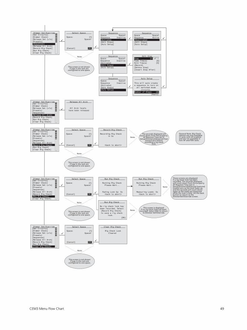
CEM3 Menu Flow Chart 49
Note:
Note:
Note:
Note:
Note:
Note:
Note:
This screen is not shownif lugs in the rack are
configured to one space.
About Dimmer 1
The seconds displayed willcount down from the property
AF Reaction Time set in Setup/Dimmers/Advanced Feat
toward zero beforerecording a rig check
look.
This screen is not shownif lugs in the rack are
configured to one space.
This screen is not shownif lugs in the rack are
configured to one space.
These screens are displayedif a rig check look has been recorded. The seconds displayed will count down from the property AF Reaction Time (set in Setup/Dimmers/Advanced Features) toward zero as the look fades up, and the seconds will count down again as the loads are measured while the look is held. Hit the back button to return to the DimmerSet/Override screen.
This screen is displayed if no rig check look has been
recorded. Select [OK] to return to Dimmer Set/Override.
This screen is not shownif lugs in the rack are
configured to one space.
General Note: Rig Check options are only available in racks with AF enabled and are not available in non-AF and FDX racks.
Space: [1] Space1
[Cancel] [OK]
Select Space
[Activate][Edit Steps][Auto Setup]
SequenceSpace Space1Sequence Inactive
[Deactivate][Edit Steps][Auto Setup]
SequenceSpace Space1Sequence Active
[Activate][Edit Steps][Auto Setup]
SequenceSpace Space1Sequence Inactive
Hold Time(s) [5][Record][Delete Step][Insert Step After]
Edit StepStep [1] of 1Fade Time(s) [0]
[Activate][Edit Steps][Auto Setup]
SequenceSpace Space1Sequence Inactive
a sequence to turn on all switched mode circuits.Number of Steps: [6] [Apply]
Auto Setup
This will auto create
Release All Arch
All Arch levels have been released
Rack #1 - CEM3 RackSystem OK
DMX A: Off DMX B: OffsACN: 1/1
[Quick Setup] [Info]
Dimmer Set/Override[Set Circuits][Dimmer Check][Release Set Lvls][Presets][Sequences][Release All Arch][Record Rig Check][Run Rig Check][Clear Rig Check]
Rack #1 - CEM3 RackSystem OK
DMX A: Off DMX B: OffsACN: 1/1
[Quick Setup] [Info]
Dimmer Set/Override[Set Circuits][Dimmer Check][Release Set Lvls][Presets][Sequences][Release All Arch][Record Rig Check][Run Rig Check][Clear Rig Check]
Rack #1 - CEM3 RackSystem OK
DMX A: Off DMX B: OffsACN: 1/1
[Quick Setup] [Info]
Dimmer Set/Override[Set Circuits][Dimmer Check][Release Set Lvls][Presets][Sequences][Release All Arch][Record Rig Check][Run Rig Check][Clear Rig Check]
Space: [1] Space1
[Cancel] [OK]
Select Space
Recording Rig Check in 5s
<back to abort>
Record Rig Check
Rack #1 - CEM3 RackSystem OK
DMX A: Off DMX B: OffsACN: 1/1
[Quick Setup] [Info]
Dimmer Set/Override[Set Circuits][Dimmer Check][Release Set Lvls][Presets][Sequences][Release All Arch][Record Rig Check][Run Rig Check][Clear Rig Check]
Space: [1] Space1
[Cancel] [OK]
Select Space
Running Rig Check Please Wait...
Fading Look Up: 5s <back to abort>
Run Rig Check
Running Rig Check Please Wait...
Measuring Loads: 5s <back to abort>
Run Rig Check
No rig check look hasbeen recorded. Select [Record Rig Check] to save a rig check look. [OK]
Run Rig Check
Rack #1 - CEM3 RackSystem OK
DMX A: Off DMX B: OffsACN: 1/1
[Quick Setup] [Info]
Dimmer Set/Override[Set Circuits][Dimmer Check][Release Set Lvls][Presets][Sequences][Release All Arch][Record Rig Check][Run Rig Check][Clear Rig Check]
Space: [1] Space1
[Cancel] [OK]
Select Space
Rig Check Look Cleared
Clear Rig Check

50 CEM3 User Manual
About
Note:
Note:
Note:
Note:
Note:
Note:
Note:
Select an error and press Enter to clear it. If the error cannot be cleared, it will stay
in the list.
[Save Manual] saves acopy of the CEM3 User Manual
to the root of the USB keywith file name
CEM3_Manual.pdf.
Temp 1 and Temp 2are only shown in FDX racks.
See Setup/UI Preferences/Temp Locale.
Recorded Load and Actual Load are only shownfor dimmers with AdvancedFeatures. See Setup/Dimmers/Advanced Features. RecordedLoad and Actual Load are onlyshown if the dimmer is in thelocal rack; they are not shownif the dimmer is in a network-connected rack.
Space name is not shownif the system has only one
space.
This screen is not shownif the system has only one
space.
This screen is not shownif the system has only one
space.
Space: [1] Space1
[Cancel] [OK]
Rack #1 - CEM3 RackSystem OK
DMX A: Off DMX B: OffsACN: 1/1
[Quick Setup] [Info]
Select Space About[Dimmers][Rack][Errors][Source Info][About CEM3]
Space 1: Space1Rack 1: CEM3 RackLug: 1Level: 0%Control Src: sACNCtrl Mode: DimmableRecorded Load: 0.0AActual Load: 12.0A
About DimmerCircuit: [1]
Rack #1 - CEM3 RackSystem OK
DMX A: Off DMX B: OffsACN: 1/1
[Quick Setup] [Info]
About[Dimmers][Rack][Errors][Source Info][About CEM3]
Rack Type: SR48CPU Temp: 97°FTemp 1: 34CTemp 2: 22CStatus: Errors ExistSW Ver: 1.6.1.9.0.XXFrequency: 60HzX:118 Y:117 Z:118Patch: DMXA: 1 ~ 96 DMXB: 1 ~ 96 sACN: 1/1 ~ 1/96Panic State: Ready
About Rack 1Name: CEM3 Rack
Rack #1 - CEM3 RackSystem OK
DMX A: Off DMX B: OffsACN: 1/1
[Quick Setup] [Info]
View/Clear ErrorsFain Fail
Rack #1 - CEM3 RackSystem OK
DMX A: Off DMX B: OffsACN: 1/1
[Quick Setup] [Info]
About[Dimmers][Rack][Errors][Source Info][About CEM3]
Rack #1 - CEM3 RackSystem OK
DMX A: Off DMX B: OffsACN: 1/1
[Quick Setup] [Info]
About[Dimmers][Rack][Errors][Source Info][About CEM3]
Space: [1] Space1
[Cancel] [OK]
Select Space Source InformationSpace: Space1 Ckt HTPSource Lvl1 Preset 33 33%2 sACN FL%3 SetLevels 55%4 ACNDirect FL%5 sACN 45%
Rack #1 - CEM3 RackSystem OK
DMX A: Off DMX B: OffsACN: 1/1
[Quick Setup] [Info]
About[Dimmers][Rack][Errors][Source Info][About CEM3]
Rack #1 - CEM3 RackSystem OK
DMX A: Off DMX B: OffsACN: 1/1
[Quick Setup] [Info]
About CEM3 ETC CEM3 v1.6.1To save a copy of the user manual, insert a USB key and press enter.
[Save Manual]

CEM3 Menu Flow Chart 51
Setup
Note:
Note:
Note:
Note:
Note:
Note:
About Dimmer 1
Module Types and Modules displayed vary by rack type.
Modules with no configurable settings (AFM, CC) are not displayed.
On Level, Off Level,On Time, and Off Time are
only shown if the Control Mode is Latch-Lock.
Threshold% is not shown in Latch-Lock mode.
Firing Modes displayeddepend on module type.
AF Mode, Reaction Time, and Sensitivity are only shownif the rack setting “AF enabled” is set to Yes. AF Mode: Load Change is not an option in FDX systems. Sensitivity is not shown in FDX systems.
sACN will be in universe/channel or absolute
format depending on the sACN setting in
Setup/UI Preferences.
Rack #1 - CEM3 RackSystem OK
DMX A: Off DMX B: OffsACN: 1/1
[Quick Setup] [Info]
Setup[Dimmers][Rack][Circuit Assignment][Patching][Network][File Operations][Panic][Time/Date][Quick Setup][UI Preferences]
Space: [1] Space1
[Cancel] [OK]
Select Space Setup Space1Ckt [1]Module: [D20AF]Control: [Dimmable]Firing: [Normal]Control SettingsPatchingDimming SettingsPanic/Arch SettingsAdvanced Features
Select Module Type[AFM][Constant Current][Dimmer][Relay][Relay (ND)][Thru Relay][Fluorescent][Low Wattage][Generic]
Select Module[D15][D15AF][D20J][D20AF][D20AFN][D20AFNJ][D20AFG][D20AFJ][D20HR]
Setup Space1Ckt [1]Module: [D20AF]Control: [Dimmable]Firing: [Normal]Control SettingsPatchingDimming SettingsPanic/Arch SettingsAdvanced Features
Control Mode[Off][Switched][Always-On][Latch-Lock][Dimmable][Smoothing][TPAuto][TPDMX]
Setup Space1Ckt [1]Module: [D20AF]Control: [Dimmable]Firing: [Normal]Control SettingsPatchingDimming SettingsPanic/Arch SettingsAdvanced Features
Firing Mode[Normal][Dim Double][Fluorescent][Reverse Phase][Thru Power]
Setup Space1Ckt [1]Module: [D20AF]Control: [Dimmable]Firing: [Normal]Control SettingsPatchingDimming SettingsPanic/Arch SettingsAdvanced Features
Control SettingsCkt: 7Curve: [Mod-Square]Threshold%: [1]On Level%: [40-50]Off Level%: [80-90]On Time (sec): [5]Off Time (sec): [5]
Curve[Square][Mod-Square][Linear][Mod-Linear][Sensor 2.0][Stage 1][Stage 2][Fluro 1][Fluro 2][VIP 90][ANDI][Custom 1][Custom 2][Custom 3][Custom 4][Custom 5]
Setup Space1Ckt [1]Module: [D20AF]Control: [Dimmable]Firing: [Normal]Control SettingsPatchingDimming SettingsPanic/Arch SettingsAdvanced Features
PatchingCkt: 7DMXA: [7]DMXA 16-Bit: [No]DMXB: [7]DMXB 16-Bit: [No]sACN: [1]/[7]sACN: 16-Bit [No]
Setup Space1Ckt [1]Module: [D20AF]Control: [Dimmable]Firing: [Normal]Control SettingsPatchingDimming SettingsPanic/Arch SettingsAdvanced Features
Dimming SettingsCkt: 7Min Scale(VAC): [6]Max Scale(VAC): [115]Regulation: [Yes]Preheat: [No]DC Out Prevent: [No]Inrush Protect: [No]Scale Load:(%) [35]
Setup Space1Ckt [1]Module: [D20AF]Control: [Dimmable]Firing: [Normal]Control SettingsPatchingDimming SettingsPanic/Arch SettingsAdvanced Features
Panic/Arch SettingsCkt: 7Allow in Panic: [Yes]Allow in Preset: [Yes]Arch Zone: [3]
Setup Space1Ckt [1]Module: [D20AF]Control: [Dimmable]Firing: [Normal]Control SettingsPatchingDimming SettingsPanic/Arch SettingsAdvanced Features
Advanced FeaturesCkt: 7AF Enabled: [Yes]AF Mode: [No-Load]Reaction Time: [00:00]Sensitivity(A): [0.5]
This screen is not shownif the system has only one
space.

52 CEM3 User Manual
Note:
Note:
Note:
Note:
Temp High Warnis in Fahrenheit (F) or Celsius (C)depending on the Temp Locale
setting inSetup/UI Preferences.
Rack #1 - CEM3 RackSystem OK
DMX A: Off DMX B: OffsACN: 1/1
[Quick Setup] [Info]
Rack #1 - CEM3 RackSystem OK
DMX A: Off DMX B: OffsACN: 1/1
[Quick Setup] [Info]
Setup[Dimmers][Rack][Circuit Assignment][Patching][Network][File Operations][Panic][Time/Date][Quick Setup][UI Preferences]
Rack SetupRack Number: [1]System Number: [1]Data Ports: DMX A: [Disabled] DMX B: [Disabled] sACN: [Enabled]Arch Priority: [100]Fan: [30]AF Enabled: [Yes]Presets on Boot: [N]Setup at Home: [Yes]Volt High Warn:[140]Temp High Warn:[149]Station Power: [Off]Remote Record: [No][Data Loss Behavior]
Rack #1 - CEM3 RackSystem OK
DMX A: Off DMX B: OffsACN: 1/1
[Quick Setup] [Info]
Reboot Required This operation will cause your CEM3 to reboot. Do you want to continue? [No] [Yes]
Rack #1 - CEM3 RackSystem OK
DMX A: Off DMX B: OffsACN: 1/1
[Quick Setup] [Info]
Rack SetupRack Number: [1]System Number: [1]Data Ports: DMX A: [Disabled] DMX B: [Disabled] sACN: [Enabled]Arch Priority: [100]Fan: [30]AF Enabled: [Yes]Presets on Boot: [N]Setup at Home: [Yes]Volt High Warn:[Yes]Temp High Warn:[Yes]Station Power: [Off]Remote Record: [No][Data Loss Behavior]
Rack #1 - CEM3 RackSystem OK
DMX A: Off DMX B: OffsACN: 1/1
[Quick Setup] [Info]
Data Loss BehaviorDMXA: [Crossfade] Fade Time: [2] Wait Time: [180] Preset Space: [1] Preset Number: [16]DMXB: [Wait & Fade] Fade Time: [2] Wait Time: [180]sACN: [Wait & Fade] Fade Time: [2] Wait Time: [180]
Rack #1 - CEM3 RackSystem OK
DMX A: Off DMX B: OffsACN: 1/1
[Quick Setup] [Info]
Setup[Dimmers][Rack][Circuit Assignment][Patching][Network][File Operations][Panic][Time/Date][Quick Setup][UI Preferences]
Circuit Assignment[Auto Assign...][Edit Circuit Layout]
Auto Ckt Assignment ConfirmationYou have selected torenumber all dimmers in the rack. Are you sure you want to do this?
[No!] [Yes/Renumber]
Auto Ckt Assignment
Numbering: [Straight]First Circuit: [1]
[Cancel] [Renumber]
Numbering: [Straight]First Circuit: [1]Space: [1]
[Cancel] [Renumber]
ConfirmationYou have selected torenumber all dimmers in the rack. Are you sure you want to do this?
[No!] [Yes/Renumber]
Circuit Assignment[Auto Assign...][Edit Circuit Layout]
Circuit SetupLug Sp Ckt Type 1 - - AFM 2 - - AFM 3 1 1 D20AF 4 1 2 D20AF 5 1 3 D20 6 1 4 D20
A T T E N T I O N !
Save Network SettingsBefore Exiting?
[No/Cancel] [Yes/Save] [Continue Editing]
A T T E N T I O N !
Save Network SettingsBefore Exiting?
[No/Cancel] [Yes/Save] [Continue Editing]
A T T E N T I O N !
Save Network SettingsBefore Exiting?
[No/Cancel] [Yes/Save] [Continue Editing]
Duplicate Numbers Duplicate Space /circuit numbers found Please correct or discard your changes [Continue Editing] [Discard Changes]
Duplicate Numbers Duplicate Space /circuit numbers found Please correct or discard your changes [Continue Editing] [Discard Changes]
Module choices vary by rack type.
Duplicate numbers screen isonly shown if there are
duplicate space or circuit numbers other than 0.

CEM3 Menu Flow Chart 53
Note:
Note:
Note:
Note:
sACN will be in universe/channel or absolute
format depending on the sACN setting in
Setup/UI Preferences.
This screen is onlyshown if the CEM3 is in a tracking backplane.
Patching[Edit DMX Patch][Edit sACN Patch] Space: [1]
Space1
[Cancel] [OK]
Select Space Rack #1 - CEM3 RackSystem OK
DMX A: Off DMX B: OffsACN: 1/1
[Quick Setup] [Info]
Patch TableCkt sACN Uni Ch 1 [ 1] [ 7] 2 [ 1] [ 8] 3 [ 1] [ 13] 4 [ 1] [ 13] 5 [ 1] [ 19] 6 [ 1] [ 20]
A T T E N T I O N !
Do you want to save your changes before exiting? [No/Cancel] [Yes/Save] [Continue Editing]
A T T E N T I O N !
Do you want to save your changes before exiting? [No/Cancel] [Yes/Save] [Continue Editing]
A T T E N T I O N !
Do you want to save your changes before exiting? [No/Cancel] [Yes/Save] [Continue Editing]
Rack #1 - CEM3 RackSystem OK
DMX A: Off DMX B: OffsACN: 1/1
[Quick Setup] [Info]
Patch TableCkt sACN 1 [ 7] 2 [ 8] 3 [ 13] 4 [ 13] 5 [ 19] 6 [ 20]
Rack #1 - CEM3 RackSystem OK
DMX A: Off DMX B: OffsACN: 1/1
[Quick Setup] [Info]
Setup[Dimmers][Rack][Circuit Assignment][Patching][Network][File Operations][Panic][Time/Date][Quick Setup][UI Preferences]
Patching[Edit DMX Patch][Edit sACN Patch] Space: [1]
Space1
[Cancel] [OK]
Select Space Rack #1 - CEM3 RackSystem OK
DMX A: Off DMX B: OffsACN: 1/1
[Quick Setup] [Info]
Patch TableCkt DMX A DMX B 1 [ 7] [ 7] 2 [ 8] [ 8] 3 [ 13] [ 13] 4 [ 14] [ 13] 5 [ 19] [ 19] 6 [ 20] [ 20]
A T T E N T I O N !
Do you want to save your changes before exiting? [No/Cancel] [Yes/Save] [Continue Editing]
A T T E N T I O N !
Do you want to save your changes before exiting? [No/Cancel] [Yes/Save] [Continue Editing]
A T T E N T I O N !
Do you want to save your changes before exiting? [No/Cancel] [Yes/Save] [Continue Editing]
Rack #1 - CEM3 RackSystem OK
DMX A: Off DMX B: OffsACN: 1/1
[Quick Setup] [Info]
Setup[Dimmers][Rack][Circuit Assignment][Patching][Network][File Operations][Panic][Time/Date][Quick Setup][UI Preferences]
Network SetupType: [Custom]IP: [ 10.101.101.101]SN: [ 255.255.0.0]GW: [ 10.101.1.11]
[Abort] [Commit]
Network SetupType: [Link Local]IP: [ 10.101.101.101]
[Abort] [Commit]
A T T E N T I O N !
Save Network SettingsBefore Exiting?
[No/Cancel] [Yes/Save] [Continue Editing]
A T T E N T I O N !
Save Network SettingsBefore Exiting?
[No/Cancel] [Yes/Save] [Continue Editing]
A T T E N T I O N !
Save Network SettingsBefore Exiting?
[No/Cancel] [Yes/Save] [Continue Editing]
Select Processor[Main(A) Processor][Backup(B) Processor]
[Cancel] [OK]
Network SetupType: [DHCP]IP: [ 10.101.101.101]SN: [ 255.255.0.0]GW: [ 10.101.1.11]
[Abort] [Commit]
This screen is not shownif the system has only one
space.
This screen is not shownif the system has only one
space.

54 CEM3 User Manual
Server SetupEnabled: [Yes]IP: [ 10.101.50.60]Upgrades:sr/conductorCFG Path:sr/conductorFile [Rack001]AutoSave: [No]
Rack #1 - CEM3 RackSystem OK
DMX A: Off DMX B: OffsACN: 1/1
[Quick Setup] [Info]
Setup[Dimmers][Rack][Circuit Assignment][Patching][Network][File Operations][Panic][Time/Date][Quick Setup][UI Preferences]
File Operations[Save to USB][Load from USB][Upgrade from USB][Save to Server][Load from Server][Upgrade from Server][Set up Server]
Save As
[Rack001].etc
[Cancel] [OK]
Load cfg fileRack001.etc
[Cancel] [OK]
Software Upgradecem3_v1_6_0.bld
Software Upgrade Are you sure you want to upgrade theoperating software tofile: cem3_v1_6_0.bld ?
[No] [Yes]
Software Upgrade Are you sure you want to upgrade theoperating software tofile: cem3_v1_6_0.bld ?
[No] [Yes]
File Operations[Save to USB][Load from USB][Upgrade from USB][Save to Server][Load from Server][Upgrade from Server][Set up Server]
File Operations[Save to USB][Load from USB][Upgrade from USB][Save to Server][Load from Server][Upgrade from Server][Set up Server]
File Operations[Save to USB][Load from USB][Upgrade from USB][Save to Server][Load from Server][Upgrade from Server][Set up Server]
File Operations[Save to USB][Load from USB][Upgrade from USB][Save to Server][Load from Server][Upgrade from Server][Set up Server]
File Operations[Save to USB][Load from USB][Upgrade from USB][Save to Server][Load from Server][Upgrade from Server][Set up Server]
File Operations[Save to USB][Load from USB][Upgrade from USB][Save to Server][Load from Server][Upgrade from Server][Set up Server]

CEM3 Menu Flow Chart 55
Note:
Note:
See Quick Setup menu flow chart.
Backlight Time willonly appear if
Backlight Mode is setto Auto.
Rack #1 - CEM3 RackSystem OK
DMX A: Off DMX B: OffsACN: 1/1
[Quick Setup] [Info]
Setup[Dimmers][Rack][Circuit Assignment][Patching][Network][File Operations][Panic][Time/Date][Quick Setup][UI Preferences]
Panic SetupIn Delay (sec): [0]Out Delay (sec): [0]Fade In (sec): [2]Fade Out (sec): [2]Shed Other Loads: [Y][Record Panic Look]
A T T E N T I O N !
Are you sure you want to overwrite the Panic Look?
[No/Cancel] [Yes/Save]
A T T E N T I O N !
Are you sure you want to overwrite the Panic Look?
[No/Cancel] [Yes/Save]
Rack #1 - CEM3 RackSystem OK
DMX A: Off DMX B: OffsACN: 1/1
[Quick Setup] [Info]
Setup[Dimmers][Rack][Circuit Assignment][Patching][Network][File Operations][Panic][Time/Date][Quick Setup][UI Preferences]
Set Time/DateMode: [Manual]Time Hour: [10]Time Minutes: [08]Year: [2017]Month: [Jun]Day: [20]
Set Time/DateMode: [Automatic]Offset from UTC: [0]Time Service: FoundCurrent Time: 20 Jun 2017 15:08
Rack #1 - CEM3 RackSystem OK
DMX A: Off DMX B: OffsACN: 1/1
[Quick Setup] [Info]
Setup[Dimmers][Rack][Circuit Assignment][Patching][Network][File Operations][Panic][Time/Date][Quick Setup][UI Preferences]
Rack #1 - CEM3 RackSystem OK
DMX A: Off DMX B: OffsACN: 1/1
[Quick Setup] [Info]
Setup[Dimmers][Rack][Circuit Assignment][Patching][Network][File Operations][Panic][Time/Date][Quick Setup][UI Preferences]
UI PreferencesBacklight Mode: [Auto]Backlight Time: [05:00]Contrast: [29]Language: [English]Temp Locale: [F]sACN: [Uni/Ch]
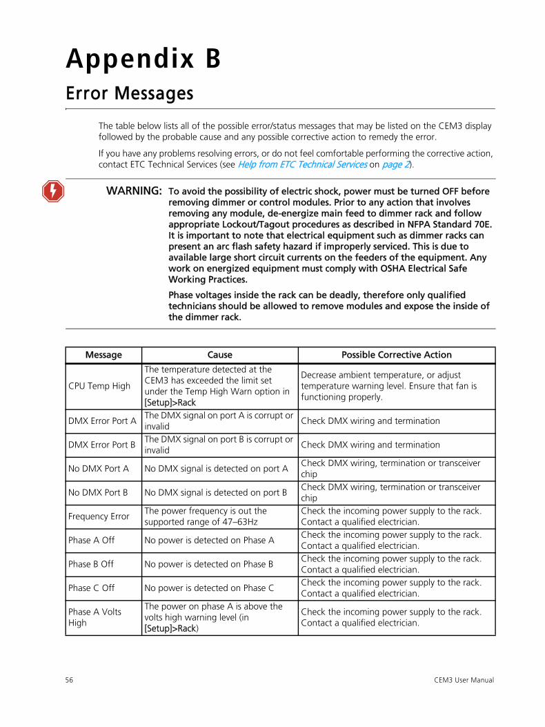
56 CEM3 User Manual
Appendix BError Messages
The table below lists all of the possible error/status messages that may be listed on the CEM3 display
followed by the probable cause and any possible corrective action to remedy the error.
If you have any problems resolving errors, or do not feel comfortable performing the corrective action,
contact ETC Technical Services (see Help from ETC Technical Services on page 2).
WARNING: To avoid the possibility of electric shock, power must be turned OFF before removing dimmer or control modules. Prior to any action that involves removing any module, de-energize main feed to dimmer rack and follow appropriate Lockout/Tagout procedures as described in NFPA Standard 70E. It is important to note that electrical equipment such as dimmer racks can present an arc flash safety hazard if improperly serviced. This is due to available large short circuit currents on the feeders of the equipment. Any work on energized equipment must comply with OSHA Electrical Safe Working Practices.
Phase voltages inside the rack can be deadly, therefore only qualified technicians should be allowed to remove modules and expose the inside of the dimmer rack.
Message Cause Possible Corrective Action
CPU Temp High
The temperature detected at the
CEM3 has exceeded the limit set
under the Temp High Warn option in
[Setup]>Rack
Decrease ambient temperature, or adjust
temperature warning level. Ensure that fan is
functioning properly.
DMX Error Port A The DMX signal on port A is corrupt or
invalid Check DMX wiring and termination
DMX Error Port B The DMX signal on port B is corrupt or
invalid Check DMX wiring and termination
No DMX Port A No DMX signal is detected on port ACheck DMX wiring, termination or transceiver
chip
No DMX Port B No DMX signal is detected on port BCheck DMX wiring, termination or transceiver
chip
Frequency Error The power frequency is out the
supported range of 47–63Hz
Check the incoming power supply to the rack.
Contact a qualified electrician.
Phase A Off No power is detected on Phase ACheck the incoming power supply to the rack.
Contact a qualified electrician.
Phase B Off No power is detected on Phase BCheck the incoming power supply to the rack.
Contact a qualified electrician.
Phase C Off No power is detected on Phase CCheck the incoming power supply to the rack.
Contact a qualified electrician.
Phase A Volts
High
The power on phase A is above the
volts high warning level (in
[Setup]>Rack)
Check the incoming power supply to the rack.
Contact a qualified electrician.

Error Messages 57
Phase B Volts
High
The power on phase B is above the
volts high warning level (in
[Setup]>Rack)
Check the incoming power supply to the rack.
Contact a qualified electrician.
Phase C Volts
High
The power on phase C is above the
volts high warning level (in
[Setup]>Rack)
Check the incoming power supply to the rack.
Contact a qualified electrician.
Phase A Volts
Low
The voltage on phase A is below the
minimum required value for the CEM3
Check the incoming power supply to the rack.
Contact a qualified electrician.
Phase B Volts Low The voltage on phase B is below the
minimum required value for the CEM3
Check the incoming power supply to the rack.
Contact a qualified electrician.
Phase C Volts
Low
The voltage on phase C is below the
minimum required value for the CEM3
Check the incoming power supply to the rack.
Contact a qualified electrician.
Phase A Overvolts The voltage on phase A is above the
maximum value for the CEM3
Check the incoming power supply to the rack.
Contact a qualified electrician.
Phase B Overvolts The voltage on phase B is above the
maximum value for the CEM3
Check the incoming power supply to the rack.
Contact a qualified electrician.
Phase C Overvolts The voltage on phase C is above the
maximum value for the CEM3
Check the incoming power supply to the rack.
Contact a qualified electrician.
Rack Memory
Error
The CEM3 is unable to communicate
with the memory chip on the
backplane
Check the CEM3 is seated correctly; Replace
backplane
Rack Detect Error
The CEM3 is unable to detect the rack
type from the DIP switches on the
backplane
Check the CEM3 is seated correctly; Replace the
backplane
Fan Fail
The CEM3 detects that the rack fan is
drawing current outside the expected
value
Check the rack fan and fan fuse.
Config Rejected A config was loaded that contained
invalid data or values
Regenerate configuration; contact ETC Technical
Services
AF Card Error 1 The CEM3 is unable to communicate
with AF card 1
Check the AF cards and CEM3 are seated
correctly; Check rack hardware for damage.
Check DIP switch settings.
AF Card Error 2 The CEM3 is unable to communicate
with AF card 2
Check the AF cards and CEM3 are seated
correctly; Check rack hardware for damage.
Check DIP switch settings.
AF Card Error 3 The CEM3 is unable to communicate
with AF card 3
Check the AF cards and CEM3 are seated
correctly; Check rack hardware for damage.
Check DIP switch settings.
AF Card Error 4 The CEM3 is unable to communicate
with AF card 4
Check the AF cards and CEM3 are seated
correctly; Check rack hardware for damage.
Check DIP switch settings.
AF Card 1
Loading AF card 1 is loading software Wait until software load has completed
AF Card 2
Loading AF card 2 is loading software Wait until software load has completed
AF Card 3
Loading AF card 3 is loading software Wait until software load has completed
AF Card 4
Loading AF card 4 is loading software Wait until software load has completed
Message Cause Possible Corrective Action

58 CEM3 User Manual
AF Dim Removed
<Dimmer Nr>
AF detects that a dimmer has been
removedReinsert dimmer; check dimmer module
AF Bkr Trip
<Dimmer Nr>
AF detects that a dimmer circuit
breaker has trippedReset circuit breaker; check dimmer module
AF RCD Trip
<Dimmer Nr>
AF detects that a dimmer circuit with
RCD has tripped due to earth leakage
Reset circuit breaker; check dimmer module and
load
AF Load High
<Dimmer Nr>
AF detects that the current load on a
circuit is higher than the recorded loadCheck load/lamps
AF Load Low
<Dimmer Nr>
AF detects that the current load on a
circuit is lower than the recorded loadCheck load/lamps
AF No Load
<Dimmer Nr>
AF detects that there is no load on a
circuitCheck load/lamps
Dim Overtemp
<Dimmer Nr>
An overtemperature condition has
been detected on a dimmer module
Clear the error from the home screen and see if it
returns.
Check rack cooling fan is running and that room
is in recommended temperature range.
If normal temp, replace module.
Message Cause Possible Corrective Action

Redundant Tracking Systems 59
Appendix CRedundant Tracking Systems
CEM3 features the ability to support dual redundant controllers in ESR24, ESR36 and ESR48 rack types,
as well as in the FDX3000 rack.
Redundant controllers provide extra security in the event of system failure, allowing a secondary
processor to immediately take control of the rack.
Redundant Tracking SwitchThe redundant tracking switch determines which controller runs the output to the dimmers. It has
three positions.
• When the switch is set to A (upper position), the upper controller has control of the dimmers.
• When the switch is set to B (lower position), the lower controller has control of the dimmers.
• When the switch is set to Auto (center position), control is automatically allocated based on the
health of the system (see below for details).
Automatic ControlTypically, in a redundant tracking system, the switch should be left in the auto position. When the
switch is set to auto, the A processor will have control by default. Control will switch to B when any of
the following events occur.
Power DMX A DMX A Network Panic
Reset
Test
About Back
Setup
Enter
Enter
thru
and
atdef
mno
wxyz
jkl
abc
tuv
#navLastA
NextB
pqrs
ghi
Power DMX A DMX A Network Panic
Reset
Test
About Back
Setup
Enter
Enter
thru
and
atdef
mno
wxyz
jkl
abc
tuv
#navLastA
NextB
pqrs
ghi
Redundant tracking in a Sensor ESR Rack
Redundant Tracking Switch
Controller A
Controller B
Redundant Tracking Switch
Controller A
Controller B
Redundant tracking in an FDX3000 Rack

60 CEM3 User Manual
Loss of network
If network connectivity is lost to one processor but not the other, control will switch to the one which
still has network connectivity.
Loss of DMX
If DMX is lost by one processor but not the other, control will switch to the one still able to receive DMX
(note that the DMX data line is interconnected between both, so this would only occur in the event of
the failure of a DMX transceiver on the processor itself).
Power errors
If one processor experiences power errors but the other does not, control will switch to the one that
does not. Again, note that the same power is connected to both processors so this would only occur
in the event of an internal failure in the processor.
Total processor loss
If communication is completely lost to one processor but not the other, then control will switch to the
processor which is still available.
Display StatusWhen tracking is active and the A processor is in control, the displays will show as follows:
Rack 1 - CEM3 RackSystem OK
DMXA: 1 DMXB: OffsACN: 2/1
[Info]
CEM3 Control
Backup Ready
Processor A
Processor B

Redundant Tracking Systems 61
When control switches to the B processor (either by automatic failover or manual control using the
switch), the displays change to the following:
The switchover from A to B for dimming happens instantaneously, so that control of lights is not lost.
However, the switchover of the user interface has built in hysteresis to eliminate bounce in certain
circumstances (for example, when DMX is lost, both processors may not see and account for the DMX
loss at exactly the same time). For this reason it may sometimes appear to take a long time for the user
interface of the backup unit to start up; however, bear in mind that despite this apparent delay,
dimming control always transfers near-instantaneously.
Configuration Management in Redundant Tracking SystemsIn a tracking CEM3 system, the two processors automatically communicate and synchronize their
configurations though the backplane. No external Ethernet network is needed for the two processors
to synchronize data.
Once you make a configuration change on one processor, that change is automatically transferred to
the second processor.
When the system boots up, it is assumed that the A processor has the most recent configuration, so
the configuration will be automatically transferred from A to B if B has a different configuration.
Firmware Upgrades in Redundant Tracking SystemsWhen you upgrade firmware in a redundant system (either via the network or using a USB key), the
firmware upgrade is automatically transferred to both processors. Once the firmware is transferred the
upgrade will occur on both processors simultaneously. Therefore it is not necessary to update both
processors independently in a rack.
Rack 1 - CEM3 RackSystem OK
DMXA: 1 DMXB: OffsACN: 2/1
[Info]
CEM3 Control
Backup ActiveProcessor A
Processor B

62 CEM3 User Manual
Appendix DFDX 3000 Dimmer Racks
CEM3 may be used as a control module in the ETC FDX3000 dimming system, providing networking
facilities, dual redundant control modules, and precision 16-bit dimming. This appendix provides
information needed to work with CEM3 in an FDX3000 system, as well as outlining the hardware of
your FDX3000 rack.
Hardware
Front Panel
The FDX3000 carrier contains two CEM3 modules in a dual redundant configuration.
PSU Indicators
The PSU indicators show the status of the two internal power supplies that supply the 15 VDC required
by FDX dimmer modules.
The two indicators should be lit at all times. If either is not lit, this could indicate a failure of the internal
power supply. If you see this condition, contact ETC Technical Services (see page 2).
Redundant Tracking Switch
The redundant tracking switch allows you to test the ability to switch from the upper (A) processor to
the lower (B) processor. If it is set to the (A) or (B) position, the A or B processor will preferentially have
control. In normal operation, the switch should be set to the center Auto position. This will ensure that
A has control unless communication is lost to A, or certain hardware failures occur on A but not B (for
example if A does not see DMX but B does).
PSU Indicators
Redundant Tracking switch

FDX 3000 Dimmer Racks 63
Rear Panel
Dimmer Outputs
The dimmer outputs connect from the FDX3000 processor to the dimmer module trays. They should
generally be preconfigured from the factory. They are grouped in blocks of 12 dimmers, from A (1–12)
through H (85–96).
Feedback
The feedback connections allow the FDX3000 to determine the status of voltage and current for
modules that support sensing. The two feedback connections should be made from the factory.
15 VDC
The 15 VDC connection provides 15 V power to the FDX dimmer modules.
Option Connector
The option connector allows field connection of the rack options such as panic (see page 30), stations
(see page 10), and a remote beacon. For information on these connections, see the termination
markings on the rear of the FDX3000 carrier.
DMX Connections
The FDX3000 processor features DMX In and Thru connections on two industry-standard 5-pin
XLR connectors. The two DMX ports, A and B, are fed to both of the redundant processors.
Ethernet Connections
Two Ethernet connections are provided using Neutrik® etherCON® connectors, which may be either
connected to a Neutrik etherCON jack or a standard RJ45 connector. Net A connects to the A (upper)
CEM3, and Net B connects to the lower. The CEM3s feature an internal switch allowing use of the rear
and front panel Ethernet connections at the same time.
Power Input
The power input connector is a three phase supply, fed from the supply in the rack. The FDX3000
processor will function regardless of any phase loss; as long as at least one phase is still active the
processor will still dim any dimmers which still have power.
DIMMER OUTPUTSA B C D E F G H
DMX A DMX B
FEEDBACK
EXT
15VDC
NET A NET B
FUSES
POWER
Pan
ic R
etu
rnP
anic
Sen
dS
tati
on
-S
tati
on
+G
rid
Pan
ic O
ut
Bea
con
+2
4VD
C
Option Connector

64 CEM3 User Manual
Fuses
The power input has three panel-mount fuse holders to protect against internal failure. The fuses
should only be replaced with the same type (2.5 A, 20 mm).
Regulatory InformationThe FDX3000 rack is certified to the following CE standards:
• Safety: EN61439-1 (Low voltage Switchgear and Controlgear assemblies)
• Electromagnetic Immunity: EN61547 (EMC Immunity for Lighting Systems)
Initial Setup
Module Count
The FDX3000 controller supports between 1 and 96 dimmers. The number of dimmers is configured
using DIP switches on the backplane of the controller.
To configure or alter the number of modules configured in your FDX system:
1: Turn off power to the rack.
2: Remove the two CEM3 modules from the FDX3000 carrier.
3: Set the DIP switches in binary to the number of modules in your rack. The DIP switches are
counted from left to right as follows:
For example, to set up the rack for 96 modules, set DIP switches 32 and 64 to ON.
4: Reinstall the CEM3 modules.
5: Power up the rack.
Module TypesThe following module types are supported in FDX:
• Blank : Used where a blank plate is fitted; gives no control and no feedback
• NoV-Nol : A dimmer module with no current or voltage feedback
• V-Nol : A dimmer module with voltage feedback but no current feedback
• NoV-I : A dimmer module with current feedback but no voltage feedback
• V-I : A dimmer module with voltage and current feedback
Advanced Features in FDXFDX3000 supports all module types available in the FDX series of racks, including the DP90 and DP90S
series of modules.
Advanced Features in an FDX rack allow modules that provide Voltage or Current feedback data to be
monitored and to report errors both at the local UI and at ETC console products and feedback
software.
64 16 8 4 2 132

FDX 3000 Dimmer Racks 65
Feedback Modes and Module Types
FDX modules may be set to one of the following module types:
To configure the module type see Menu Structure on page 10.
Roasting Short Protection
FDX3000 features a unique method for providing additional safety in the event of a roasting short. A
roasting short can occur when a dimmer is at a low level and driven into a short circuit load with a long
cable.
Because the dimmer is at a low level, the roasting short does not draw enough current to trip the circuit
breaker. However, a roasting short is still a dangerous condition as currents can flow at a high enough
amperage to cause heat or, in extreme circumstances, fire.
The FDX3000 rack has the capability to detect this condition. When a roasting short is detected by a
module set to V/I mode, the dimmer is automatically driven to full, allowing the high current of the
short circuit to trip the circuit breaker.
This utility is automatically enabled on any modules set to V/I mode.
Module Type Purpose Error Messages
NoV-NoIModule provides no
monitoringNo AF Error messages will be produced
NoV-IModule monitors current,
not voltage
No Load messages will be produced if the channel is
turned
V-NolModule monitors voltage,
not current
Breaker Trip messages will be produced if the channel
is turned on with the breaker turned off.
V-IModule monitors both
voltage and current
Both Breaker Trip and No Load messages may be
produced and the roasting short protecting feature
will be enabled.
FDX 3000 Rack
LIVE
NEUTRAL
Short Circuit
Load

66 CEM3 User Manual
FDX2000 vs. FDX3000 Dimmer Curve ComparisonCurves in FDX3000 reference voltage rather than power. Therefore the following table will help to
show the correlation between FDX2000 curve names and FDX3000 curve names..
FDX2000 Curve English / German
FDX3000 CurveEnglish
Comment
1 = Linear (default) Square Proportional to RMS power output
(FDX2000 Linear)
2 = Stage1 Stage 1 Built to match an old Siemens curve
3 = Stage2 Stage 2 Built to match an old Siemens curve
4 = Log Linear Proportional to RMS voltage output
5 = Fluor1 Fluor 1
6 = Fluor2 Fluor 2
7 = Pow/2 n.a. Obsolete
8 = 10% n.a. Obsolete
9 = VIP90 VIP
10 = ANDI ANDI
n.a Mod-Square (Default)
n.a Mod-Linear
n.a Sensor 2.0 Older mod square law

Corporate Headquarters Middleton, WI, USA Tel +608 831 4116 Service: (Americas) [email protected], UK Tel +44 (0)20 8896 1000 Service: (UK) [email protected], IT Tel +39 (06) 32 111 683 Service: (UK) [email protected], DE Tel +49 (80 24) 47 00-0 Service: (DE) [email protected] Kong Tel +852 2799 1220 Service: (Asia) [email protected]: etcconnect.com © 2017 Electronic Theatre Controls, Inc. Product information and specifications subject to change. ETC intends this document to be provided in its entirety.7140M1200-1.6.1 Rev A Released 2017-08