sensors and transducers rev iii - philadelphia university. sensors and... · sensors and...
TRANSCRIPT

D R . T A R E K A . T U T U N J I
P H I L A D E L P H I A U N I V E R S I T Y , J O R D A N
2 0 1 4
Sensors and Transducers REV III

Transducers
A transducer is defined as a device that converts a signal from one physical form to a corresponding signal, which has a different physical form.
In a control system, the transducer senses the magnitude or intensity of the controlled output and produces a proportional signal in an energy form suitable for transmission along the feedback path to the comparator.

Sensors
A sensor is defined as a device that produces an output signal for the purpose of sensing of a physical phenomenon.
The element of the transducer which senses the controlled output is called the sensor; the remaining elements of a transducer serve to convert the sensor output to the energy form required by the feedback path

Transducers
Transducers are usually considered in two groups:
Motion and force transducers, which are mainly associated with servomechanisms
Process transducers, which are mainly associated with process control systems

General Instrumentation System
[Ref.] Shetty

Sensor Classification
[Ref.] Shetty

Elements of Instrumentation System
[Ref.] Shetty

Sensor Types
Position sensors
Velocity sensors
Acceleration sensors
Proximity sensors
Load and Pressure sensors
Temperature sensors
Flow sensors
Liquid-level sensors

P O T E N T I O M E T E R S
O P T I C A L R O T A R Y E N C O D E R S
L V D T
Position Sensors

Potentiometer
[Ref.] Kilian + Shetty

Potentiometer as Position Sensor
[Ref.] Kilian
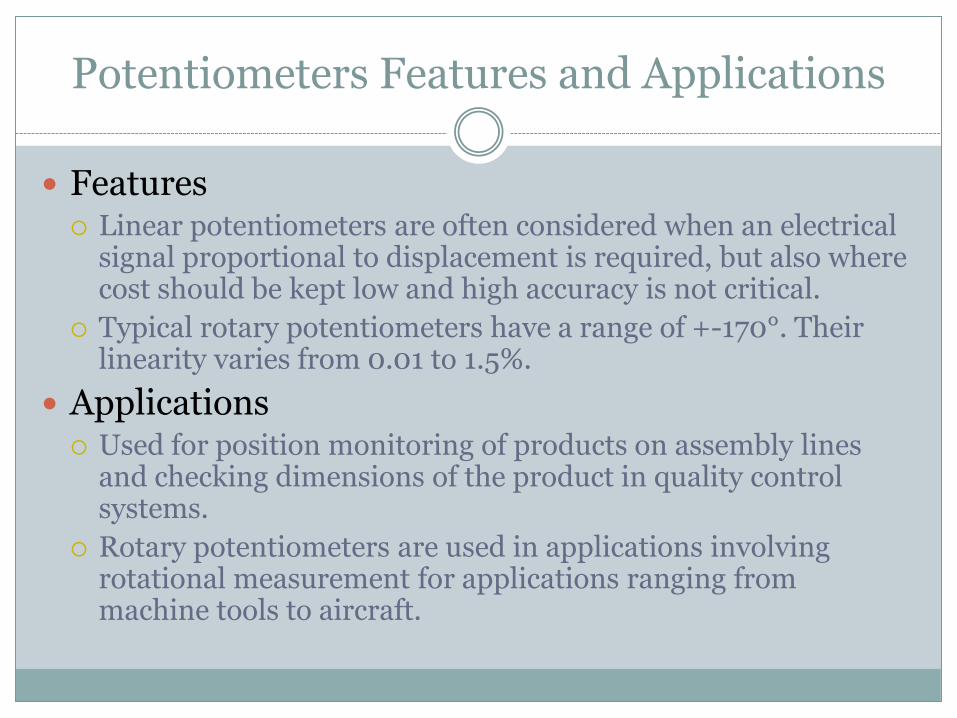
Potentiometers Features and Applications
Features Linear potentiometers are often considered when an electrical
signal proportional to displacement is required, but also where cost should be kept low and high accuracy is not critical.
Typical rotary potentiometers have a range of +-170°. Their linearity varies from 0.01 to 1.5%.
Applications Used for position monitoring of products on assembly lines
and checking dimensions of the product in quality control systems.
Rotary potentiometers are used in applications involving rotational measurement for applications ranging from machine tools to aircraft.

Linear Variable Displacement Transformer (LVDT)
[Ref.] Kilian

Linear Variable Displacement Transformer (LVDT)
[Ref.] Kilian
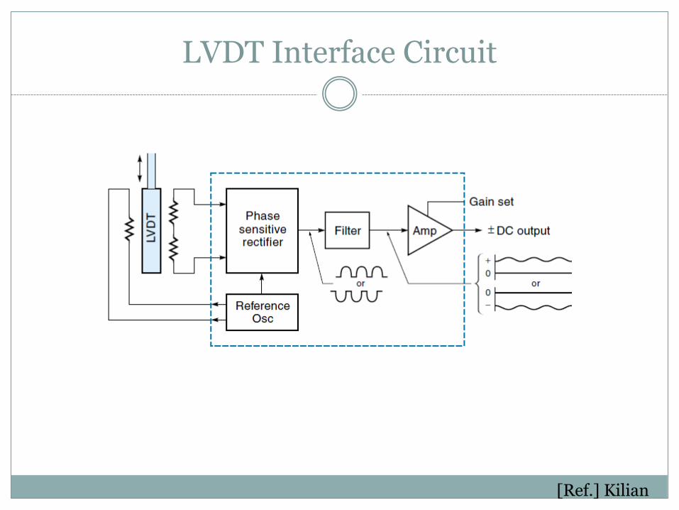
LVDT Interface Circuit
[Ref.] Kilian

LVDT Features and Applications
Features: High resolution, high accuracy, and good stability make them an ideal
for applications involving short displacement measurements. Sensitive transducers provide resolution down to about 0.05 mm. They
have operating ranges from about 0.1 to 300 mm. Accuracy is 0.5 mm of full-scale reading. Less sensitive to wide ranges in temperature than potentiometers.
Applications Measurement of precision gap between weld torch and work surface in
welding applications. Measurement of the thickness of plates in rolling mills. Detection of surface irregularity of parts after they are machined.
Angular speed measurement of a rotating device. Precise detection of specimen size. Liquid level applications.

Rotary Encoders Applications
Encoders are used for measurement of linear or angular position, velocity, and direction of movement.
Used in computerized manufacturing machines, motion-control
applications, and quality assurance of equipment. Used in tensile-test instruments to precisely measure the ball screw
position. Used in automated test stands used when angular positions of
windshield wiper drives and switch positions are tested. Incremental encoders commonly are used for counting applications.

Optical Encoding: Absolute
[Ref.] Kilian

Optical Encoding: Incremental
[Ref.] Kilian

Encoder Interface Circuit
[Ref.] Kilian

O P T I C A L A N D D I R E C T C U R R E N T T A C H O M E T E R S
Velocity Sensors

Tachometer
[Ref.] Kilian

Tachometer Example

Tachometer Interface

Vibration and piezoelectric
Acceleration Sensors

Acceleration Sensors
Measurement of acceleration is important for systems subject to shock and vibration.
Seismic mass
The seismic mass type accelerometer is based on the relative motion between a mass and the supporting structure. The natural frequency of the seismic mass limits its use to low to medium frequency applications.
Piezoelectric accelerometer.
The piezoelectric accelerometer, however, is compact and more suitable for high frequency applications

Vibration Sensors: Seismic Mass

Vibration Sensors: Piezoelectric
[Ref.] Shetty

Accelerometer
An accelerometer is a device that measures indirect acceleration. Rather than measuring the coordinate acceleration (rate of change of velocity), the accelerometer sees the acceleration associated with the phenomenon of weight experienced by any test mass at rest in the frame of reference of the accelerometer device. For example, an accelerometer at rest on the surface of the earth will measure an
acceleration g= 9.81 m/s2 straight upwards, due to its weight. By contrast, accelerometers in free fall or at rest in outer space will measure zero.
Another term for the type of acceleration that accelerometers can measure is g-force acceleration.
Accelerometers have multiple applications in industry and science. Highly sensitive accelerometers are components of inertial navigation systems
for aircraft and missiles. Accelerometers are used to detect and monitor vibration in rotating machinery.

Gyroscope
A gyroscope is a device for measuring or maintaining orientation, based on the principles of angular momentum. Mechanically, a gyroscope is a spinning wheel or disc in which the axle is free to assume any orientation. Although this orientation does not remain fixed, it changes in
response to an external torque much less and in a different direction than it would with the large angular momentum associated with the disc's high rate of spin and moment of inertia.
Electronic, microchip-packaged MEMS gyroscope devices found in consumer electronic devices, solid-state ring lasers, fibre optic gyroscopes, and the extremely sensitive quantum gyroscope.

Inertial Measurement Unit (IMU)
An inertial measurement unit (IMU) is an electronic device that measures and reports on a craft's velocity, orientation, and gravitational forces, using a combination of accelerometers and gyroscopes, sometimes also magnetometers. IMUs are typically used to maneuver aircraft, including unmanned aerial vehicles (UAVs) and spacecrafts

Flight Control

L I M I T S W I T C H E S
H A L L - E F F E C T S W I T C H E S
O P T I C A L
C A P A C I T I V E
I N D U C T I V E
U L T R A S O N I C
Proximity Sensors

Proximity Sensors
They are used to sense the proximity of an object relative to another object. They usually provide ON/Off signal indicating the presence or absence of an object.
Examples: Capacitance, inductance, photoelectric, and hall effect Capacitance types are similar to inductance except the proximity
of an object changes the gap and affects the capacitance.
Inductance proximity sensors consist of a coil wound around a soft iron core. The inductance of the sensor changes when a ferrous object is in its proximity. This change is converted to a voltage-triggered switch.

Capacitive Transducer
A change in capacitance can be brought about by varying the following parameters. Changing the distance between the two parallel electrodes. Changing the dielectric constant, permittivity, of dielectric medium . Changing the area of the electrodes, A.
Features Capacitance transducers can be used in high humidity, high temperature, or
nuclear radiated zones. They are very sensitive and have high resolution. They can be expensive and need
significant signal conditioners.
Applications Capacitance transducers are generally only suitable for measuring small
displacements. Examples of these are surface profile sensing, wear measurement, or crack growth.

Capacitive Proximity

Capacitive Proximity Sensor
[Ref.] Bartlet

Specifications

Inductive Transducer
An inductive sensor is an electronic proximity sensor, which detects metallic objects without touching them.
The sensor consists of an induction loop. Electric
current generates a magnetic field, which collapses generating a current that falls asymptotically toward zero from its initial level when the input electricity ceases.
The inductance of the loop changes according to the material
inside it and since metals are much more effective inductors than other materials the presence of metal increases the current flowing through the loop. This change can be detected by sensing circuitry, which can signal to some other device whenever metal is detected.

Inductive Sensors

Inductive Proximity Sensor
[Ref.] Bartlet

Capacitive vs. Inductive
Capacitive and inductive proximity sensors are similar in size, shape, and concept to inductive proximity sensors. The main difference between the two types is that capacitive
proximity sensors produce an electrostatic field instead of an electromagnetic field
Capacitive sensing is suitable for detecting metals, nonmetals, solids, and liquids.
Inductive sensing is best suited for metallic targets because it is both a reliable and a more affordable technology.

Proximity Sensors
Photoelectric sensors are normally aligned with an infrared light source. The proximity of a moving object interrupts the light beam causing the voltage level to change.
Hall effect voltage is produced when a current-carrying conductor is exposed to a transverse magnetic field. The voltage is proportional to transverse distance between the hall effect sensor and an object in its proximity

Photo-detectors
[Ref.] Kilian

Optical Slotted Coupler

Hall Effect
Hall effect transducers are used to measure position, displacement, level, and flow. They can be used as an analog motion sensing device as well as a digital device.
The Hall effect occurs when a strip of conducting material carries current in the presence of a transverse magnetic field. Hall-Effect Sensors utilise semiconductor Hall chips and a magnet mounted to a shaft or
push rod. As the chips change their output in response to the proximity of the magnetic field, changes in its position can be measured.
Principle of operation: An external voltage source is used to establish a current (I ) in the semiconductor crystal. The output voltage (VH) is sensed across the sides of the crystal, perpendicular to the current direction. When a magnetic field is brought near, the negative charges are deflected to one side producing a voltage.
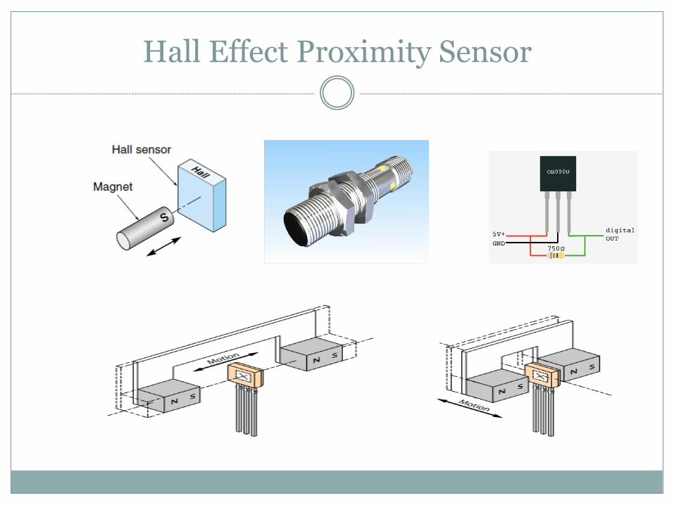
Hall Effect Proximity Sensor

Range Sensors: Ultrasonic
Ultrasonic proximity sensors use a transducer to send and receive high frequency sound signals. When a target enters the beam the sound is reflected back to the switch, causing it to energize or deenergize the output circuit.

Ultrasonic Sensors

Range Sensors: Laser

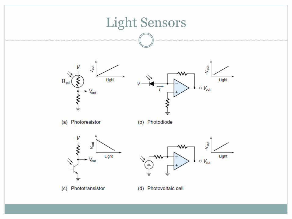
Light Sensors

Light Sensors
Light intensity and full field vision are two important measurements used in many control applications.
Phototransistors, photoresistors, and photodiodes are
some of the more common type of light intensity sensors. When the photoresistor is exposed to light, its resistance
drops in proportion to the intensity of light. When interfaced with a circuit and balanced, the change in light intensity will show up as change in voltage.
These sensors are simple, reliable, and cheap, used
widely for measuring light intensity.
Light Sensors

Bonded-wire strain gauges Semiconductor force strain gauges
Low-force sensors Bourdon tubes
Bellows Semiconductor pressure sensors
Load Sensors

Force, Torque, and Pressure Sensors
Common force/torque sensors are: strain gauge and piezoelectric.
Both are available to measure force and/or torque either in
one axis or multiple axes.
The strain gauge make use of mechanical members that experiences elastic deflection when loaded. These types of sensors are limited by their natural frequency.
The piezoelectric sensors are particularly suitable for dynamic
loadings in a wide range of frequencies. They provide high stiffness, high resolution over a wide measurement range, and are compact.

Strain Gauges
[Ref.] Shetty

Strain Gauges
[Ref.] Kilian

Load Cells
[Ref.] Kilian

Load Cells

Strain Gauges
Features A high gauge factor increases its sensitivity and causes a larger change in
resistance for a particular strain. High resistance of the strain gauge minimizes the effect of resistance
variation in the signal processing circuitry. Choose gauge characteristics such that resistance is a linear function of strain.
For dynamic measurements, the linearity should be maintained over the desired frequency range.
Low temperature coefficient and absence of the hysteresis effect add to the precision.
Applications Strain-gauge transducers are used for measuring strain, force, torque,
pressure, and vibration. In some applications, strain gauges are used as a primary or secondary
sensor in combination with other sensors.

Pressure Sensors: Bourdon and Bellows
[Ref.] Kilian

Semiconductor Pressure Sensor
[Ref.] Kilian

Bimetallic temperature sensors
Thermocouples
Resistance temperature detectors
Thermistors
IC temperature sensors.
Temperature Sensors

Temperature Sensors
Temperature measurement is based on one of the following principles.
1. Contact voltage between two dissimilar metals. 2. Change in electrical resistance. 3. Change in radiated energy. The most common temperature sensors are: Thermocouples Thermisters Resistance Temperature Detectors (RTD) Infrared types

Thermocouples
Thermocouples are the most versatile, inexpensive, and have a wide range (up to 1200 C typical). A thermocouple simply consists of two dissimilar metal wires joined at the ends to create the sensing junction.
When used in conjunction with a reference junction, the temperature difference between the reference junction and the actual temperature shows up as a voltage potential.

Thermocouple
[Ref.] Kilian
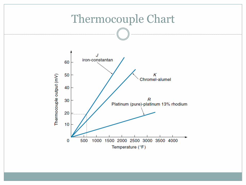
Thermocouple Chart

Standard Thermocouple Characteristics

Temperature Sensors
The RTDs use the phenomenon that the resistance of a metal changes with temperature. They are, however, linear over a wide range and most stable
Thermistors are semiconductor devices whose resistance
changes as the temperature changes. They are good for very high sensitivity measurements in a limited range of up to 100 C. The relationship between the temperature and the resistance is nonlinear.
Infrared type sensors use the radiation heat to sense the
temperature from a distance. These noncontact sensors can also be used to sense a field of vision to generate a thermal map of a surface

RTD
RTD is a length of wire whose resistance is a function of temperature.
It consists of a wire that is wound in the shape of a coil to
achieve small size and improve thermal conductivity.

Thermistor
[Ref.] Kilian
Thermistor operation relies on the principle of change in semiconductor resistance with change in temperature

IC Temperature Sensors: LM35

LM35 Temperature Sensor
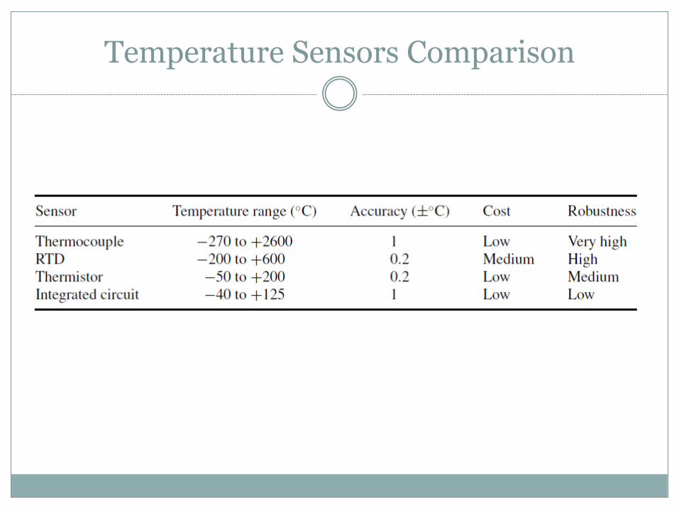
Temperature Sensors Comparison

Orifice plates
Venturis
Pitot tubes
Turbines
Magnetic flowmeters.
Flow Sensors

Flow Sensors
The fluid medium can be liquid, gas, or a mixture of the two. The flow could be laminar or turbulent and can be a time-
varying phenomenon. The venturi meter and orifice plate restrict the flow and use
the pressure difference to determine the flow rate. The rotameter and the turbine meters when placed in the
flow path, rotate at a speed proportional to the flowrate. The electromagnetic flow meters use noncontact method.
Magnetic field is applied in the transverse direction of the flow and the fluid acts as the conductor to induce voltage proportional to the flow rate.

Flow Sensors
Ultrasonic flow meters measure fluid velocity by passing high-frequency sound waves through fluid. Transmitters (T) provide the sound signal source. As the wave travels
towards the receivers (R), its velocity is influenced by the velocity of the fluid flow due to the doppler effect.
The control circuit compares the time to interpret the flow rate. This can be used for very high flow rates and can also be used for both upstream and downstream flow. The other advantage is that it can be used for corrosive fluids, fluids with abrasive particles, as it is like a noncontact sensor.
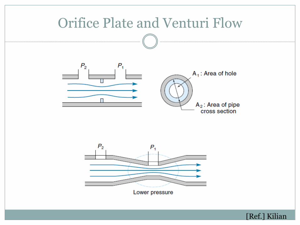
Orifice Plate and Venturi Flow
[Ref.] Kilian
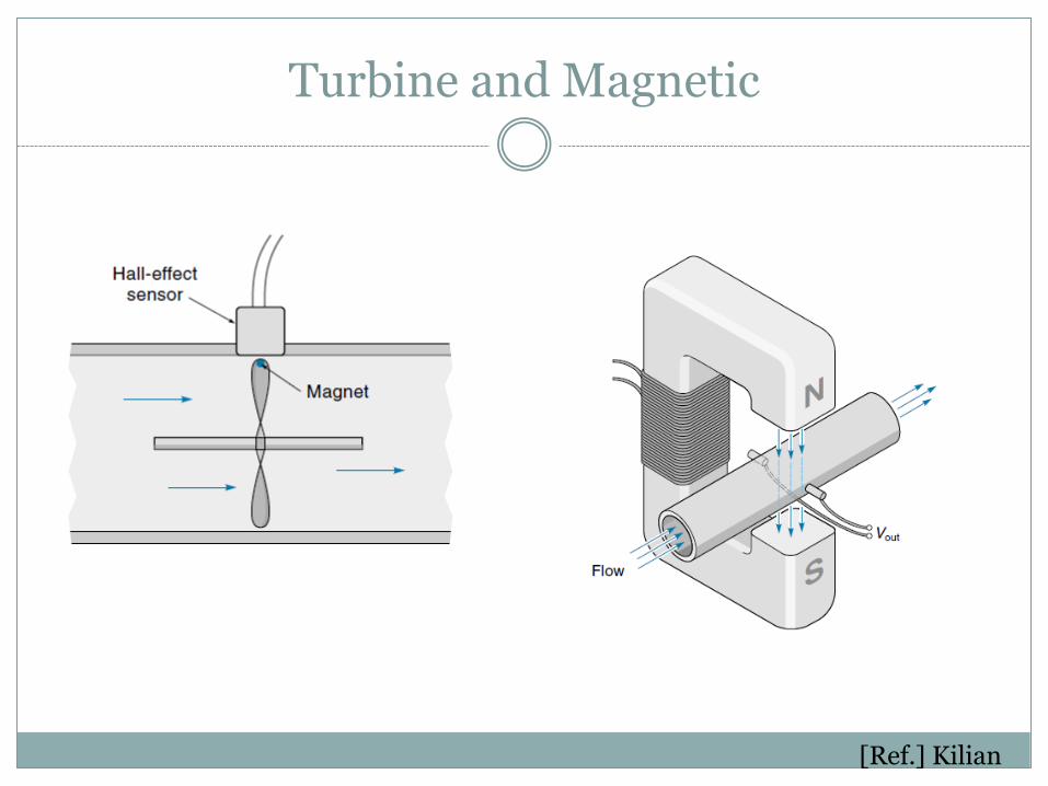
Turbine and Magnetic
[Ref.] Kilian

Ultrasonic Flow Sensors
Ultrasonic flow meters measure fluid velocity by passing high frequency sound waves through the fluid.
They operate by measuring the transmission time difference of an ultrasonic beam passed through a homogeneous fluid contained in a pipe at both an upstream and downstream location.
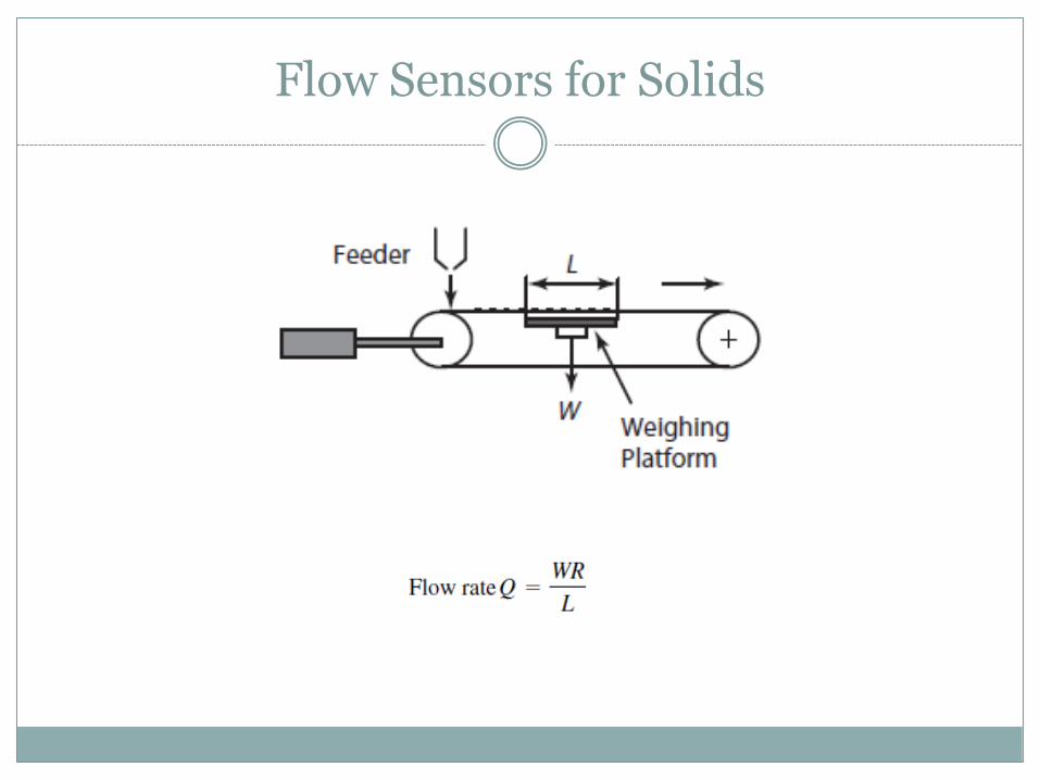
Flow Sensors for Solids

D I S C R E T E A N D C O N T I N U O U S T Y P E S
Level Sensors

Level Sensors
Level sensors are used to measure the fluid level in tanks.
There are discrete and continuous level sensors

Discrete Level Sensor
[Ref.] Kilian
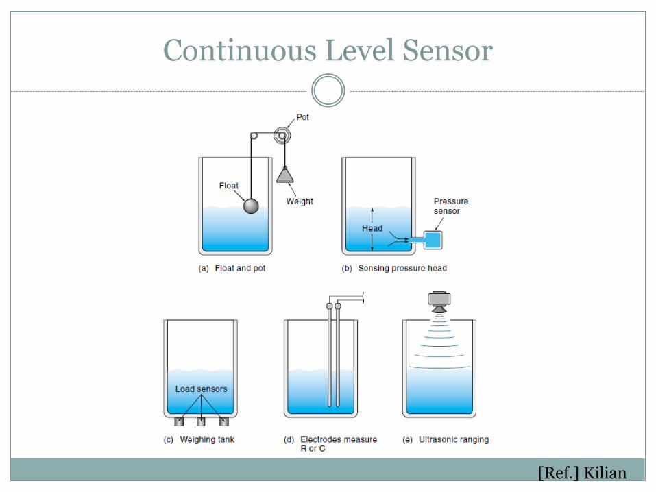
Continuous Level Sensor
[Ref.] Kilian

Smart Sensors

Smart Sensors
Smart sensors combine the sensing element with microprocessor capabilities that provides embedded intelligence.
Advantages include: fast signal processing , high signal-to-noise-
ratio, self-testing, auto-calibration, failure prevention
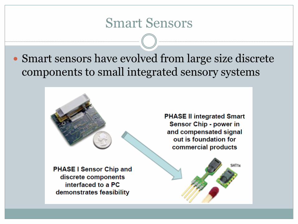
Smart Sensors
Smart sensors have evolved from large size discrete components to small integrated sensory systems

Smart Material Sensors
New smart materials are being used as sensors.
Examples are: Optic fibers, piezoelectric, and magnetostrictive materials
Optic fibers Can be used to sense strain, liquid level, force, and temperature with very high
resolution. They have found numerous applications in smart structure applications such as
damage sensors, vibration sensors, and cure-monitoring sensors.
The basic principle of operation of an embedded optic fiber used to sense displacement, force, or temperature. The relative change in the transmitted intensity or spectrum is proportional to the change in the sensed parameter.

Piezoelectric Transducer
Piezoelectric materials, when subjected to mechanical force or stress along specific planes, generate electric charge.
The best-known natural material is quartz crystal (SiO2).
Rochelle salt is also considered a natural piezoelectric material.

Micro Sensors
Micro Electro Mechanical Systems (MEMS) is a class of systems that are physically small. These systems have both electrical and mechanical parts as an integrated circuit. They include micro-sensors and micro-actuators
Microsensors are the miniaturized version of the
conventional macrosensors with improved performance and reduced cost.
Silicon micromachining technology has helped the
development of many microsensors and continues to be one of the most active research and development topics in this area.

Micro and Nano Sensors
Microsensors have found applications in medical technology. A fiberscope of approximately 0.2 mm in diameter has been
developed to inspect flaws inside tubes. A microtactile sensor, which uses laser light to detect the contact
between a catheter and the inner wall of blood vessels during insertion that has sensitivity in the range of 1 mN.
Similarly, the progress made in the area of nanotechnology has fuelled the development of nanosensors. These are relatively new sensors that take one step further in the direction of miniaturization and are expected to open new avenues for sensing applications.

Transducers Classification
Potentiometric Potentiometric transducers apply the principle of change in resistance of
material in the sensor.
Capacitance Capacitance transducers apply the principle of capacitance variation
between a set of plate assemblies.
Inductance Inductance transducers are based on the principle of variation of
inductance by the insertion of core material into an inductor. Inductance variations serve as a measure of displacement.
Piezoelectric Piezoelectric transducers are based on the principle of charge
generation. Whenever certain piezoelectric crystals are subjected to mechanical motion, an electric voltage is induced. This effect can be reversed by applying an electric voltage and deforming the crystal.

Signal Conditioning

Signal Conditioning
Filtering and Amplifying measured signals from sensors
Signal conditioning circuits improve the quality of signals generated by transducers before they are converted into digital signals by the PC's data-acquisition hardware.
Tarek A. Tutunji

Signal Conditioning
The signal conditioner accepts the electrical output of the transducer and transmits the signal to the comparator in a form compatible with the reference input. The functions of the signal conditioner include:
Amplification Isolation Sampling Noise elimination Linearization Span and reference shifting
Math manipulation differentiation, division, integration,
multiplication, root finding, squaring, subtraction, or summation
Signal conversion DC–AC, AC–DC, frequency–voltage,
voltage–frequency, digital–analog, analog–digital
Buffering Digitizing Filtering Impedance matching Wave shaping Phase shifting
In a digital control system, many of
the signal conditioning functions listed here can also be accomplished by software

Filtering
Electronic filters are circuits which perform signal processing functions, specifically to eliminate unwanted frequencies and/or enhance wanted ones

Example: Low Pass Filter
RCsRsC
sC
Vin
VoutsH
1
1
/1
/1)(
Passes low frequencies Blocks high frequencies

Amplification
Amplification expands the range of the transducer signals so that they match the input range of the A/D converter. For example, a x10 amplifier maps transducer signals
which range from 0 to 1 V into the range 0 to 10 V before they go into the A/D converter.

Example: Non-inverting amplifier
VinVoutRi
f-R
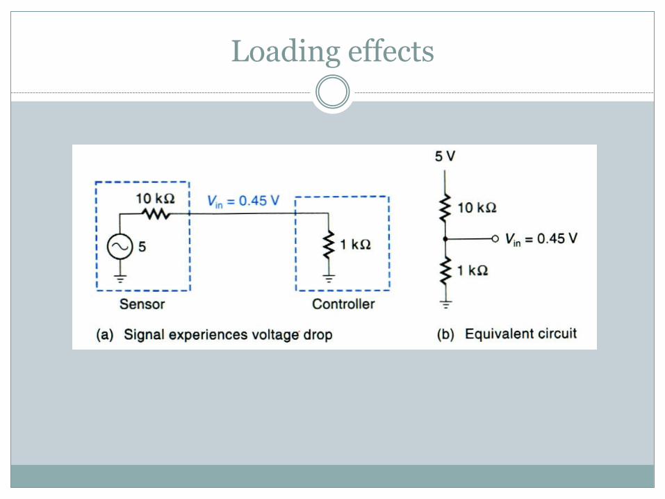
Loading effects

Preventing Loading
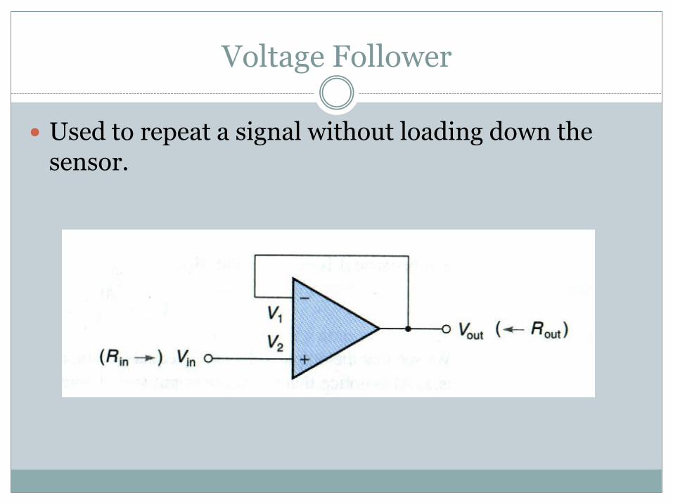
Voltage Follower
Used to repeat a signal without loading down the sensor.

Difference Amplifier
By letting: Ra = Rb Rf = Rg
)VV(V abOUT a
f
R
R
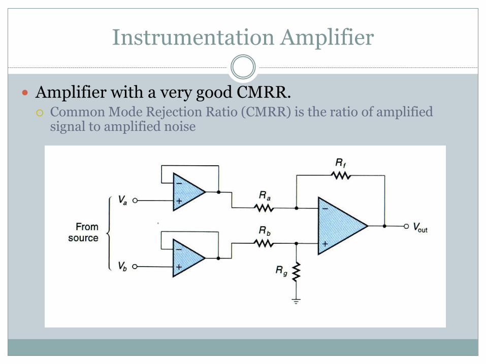
Instrumentation Amplifier
Amplifier with a very good CMRR. Common Mode Rejection Ratio (CMRR) is the ratio of amplified
signal to amplified noise

Op Amps

Integrator Circuit
Output voltage is proportional to the area under a signal curve.

Differentiator Circuit
Output is proportional to the rate of change of the input.

Active Low Pass Filter

Ground-Loop
Source and Load should not be separately grounded because a difference on potential at each ground-point will create a ground-loop of current flow.

Ground Loops
Best solution for connecting to earth-ground.

Isolation Circuits
Allow for 2 circuits to have different source voltages and grounds.
Ground Isolation
Signal Isolation
Spike protection

Transformer Coupled
Good for modulated signals.
Slow-changing DC signals must be modulated to magnetically couple the transformers.

Digital Optocoupler
Provides isolation of TTL level voltages.
Also called opto-isolators.

Interface
Interfacing of high voltage, noisy systems to a controller.
Signal travels in only one direction.

Optical Linear Signal Isolation
An LED and matched phototransistors are used to provide optical isolation.
The feedback phototransistor provides feedback due to non-linear response of the LED.
Shielding
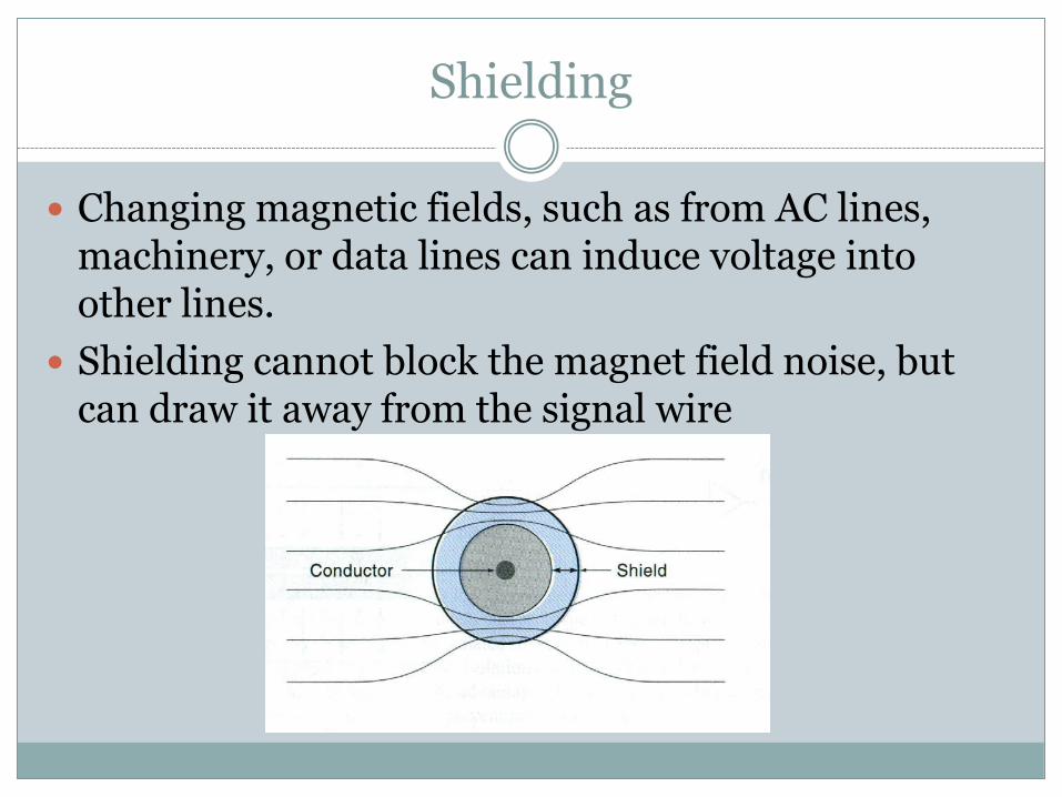
Changing magnetic fields, such as from AC lines, machinery, or data lines can induce voltage into other lines.
Shielding cannot block the magnet field noise, but can draw it away from the signal wire
Shielding
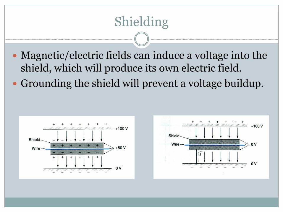
Magnetic/electric fields can induce a voltage into the shield, which will produce its own electric field.
Grounding the shield will prevent a voltage buildup.

Grouding
Single-point grounds should be used to prevent ground-loop problems.
Best choice is to use a Single-Point Ground at the controller.

Grounding
When a single point ground cannot be used, an isolation circuit with individually grounds should be used.

Calibration
The sensor manufacturer usually provides the calibration curves. If the sensors are stable with no drift, there is no need to recalibrate. However, often the sensor may have to be recalibrated after integrating it with a signal conditioning system.
This essentially requires that a known input signal is provided to the sensor and its output recorded to establish a correct output scale. This process proves the ability to measure reliably and enhances the confidence.

Calibration
If the sensor is used to measure a time-varying input, dynamic calibration becomes necessary.
Use of sinusoidal inputs is the most simple and reliable way of dynamic calibration.
Another test is looking at the transient behavior of step response.

Summary
Sensors and transducers are essential elements in mechatronic systems because they are used to measure the controlled variable and transmit to the controller as feedback
Sensors can be divided according to the variable that they
measure: Position/Velocity Acceleration Force/Torque/Pressure Flow Temperature Proximity/Range

References
Mechatronics System Design 2nd edition by Shetty and Kolk. Cenage Learning 2011
Modern Control Technology: Components and Systems 2nd edition by Kilian. Delmer Publication