sentry sedate user’s manual / instructions sentry … · introduction of moisture or other...
TRANSCRIPT
1
Parker Hannifin Corporation Precision Fluidics Division Porter Instrument
245 Township Line Road Hatfield, PA 19440 Office 215-723-4000/Fax 215-723-5106
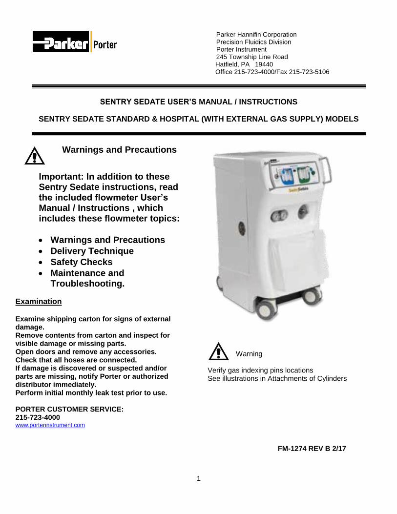
SENTRY SEDATE USER’S MANUAL / INSTRUCTIONS
SENTRY SEDATE STANDARD & HOSPITAL (WITH EXTERNAL GAS SUPPLY) MODELS
Warnings and Precautions
Important: In addition to these Sentry Sedate instructions, read the included flowmeter User’s Manual / Instructions , which includes these flowmeter topics:
Warnings and Precautions
Delivery Technique
Safety Checks
Maintenance and Troubleshooting.
Examination Examine shipping carton for signs of external damage. Remove contents from carton and inspect for visible damage or missing parts. Open doors and remove any accessories. Check that all hoses are connected. If damage is discovered or suspected and/or parts are missing, notify Porter or authorized distributor immediately. Perform initial monthly leak test prior to use. PORTER CUSTOMER SERVICE: 215-723-4000 www.porterinstrument.com
Warning
Verify gas indexing pins locations See illustrations in Attachments of Cylinders
FM-1274 REV B 2/17
2
Warnings and Precautions These warnings and precautions are to help
you to understand how to safely operate the Sentry Sedate conscious sedation system. A WARNING alerts you to a possible hazard to people. A CAUTION alerts you to the possibility of equipment damage.
WARNING: Sentry Hospital Model: New or modified installations - properly connected gas pipelines (external supply to Sentry Sedate) are absolutely essential to patient safety. The ultimate responsibility of assuring that lines are not crossed rests with the user. See next page for details.
WARNING: Porter Instrument equipment utilizes the cross+protection system. The flexible hose and connectors that connect to blocks and the flowmeter input internal to the Sentry Sedate housing, and the supply connections for the external supply (Hospital Model), are diameter indexed; 3/8” O.D. for Nitrous Oxide and ½” O.D. for Oxygen. The cross+protection system is designed to prevent misconnection of Oxygen and Nitrous Oxide hoses. DO NOT ATTEMPT TO CHANGE THE DIAMETERS OR CONNECTORS OF THE SENTRY SEDATE! Tampering with the cross+protection system constitutes acceptance of liability by the installer.
WARNING: The Sentry Sedate conscious sedation system, with Flowmeter, is intended to be used by medical personnel trained in the flowmeter device use and the use of nitrous oxide and oxygen for medical applications. WARNING: Do not use the Flowmeter device for the administration of general anesthesia or as a part of, or in conjunction with, a general anesthesia administration system. WARNING: Use Scavenging: Medical workers are exposed to N2O during administration of N2O/O2 conscious sedation analgesia. Controls are effective in the patient treatment area to achieve low levels of ppm (parts per million) exposure. Controls include System Maintenance, Ventilation and Work Practices. Your accessory Scavenger System is an important part of the system of controls in medical settings.
Inspect and maintain the analgesia delivery system to prevent N2O leaks in all hoses, connections and fittings. This includes the delivery system as accessory to Sentry Sedate and the hoses and connections internal to the Sentry Sedate housing. Have all leaks repaired immediately. WARNING: (Sentry Sedate; connections for external gas supplies): 50 - 55 psi line pressure. Follow safe connection protocol in this order: Connect external gas supply hoses to DISS (Diameter Indexed Safety System) fittings of Sentry Sedate (O2 first); then connect to external supply source. Do not disconnect with supply line pressurized [disconnect at supply source per appropriate safe protocol]. N2O DISS connection on left; O2 DISS connection on right. WARNING: Cylinder (N2O/O2) Security: When not in use, to secure on-board tanks, close and lock doors. For added security, disconnect hoses from unit [and external supply source] and lock inside the housing of Sentry Sedate. Note: With doors locked and external supplies connected (or tank valves ON), flowmeter will deliver mixed gases. WARNING: During any power outage, remember to turn OFF the flowmeter and manually turn OFF the tank valves (or external supplies). With centralized, electrically powered gas systems, if gas was flowing when the power went out and the flowmeter is left ON, gas will be flowing when the power is restored. CAUTION: Always use clean, dry medical grade gases. Introduction of moisture or other contaminants into the system and flowmeter device may result in defective operation. CAUTION: Do not attempt to repair, alter or calibrate the system or flowmeter device (except as directed in Porter User’s Manuals). Unauthorized repair, alteration or misuse of the flowmeter device is likely to adversely affect the performance and will void the warranty. CAUTION: Never oil or grease any part of this system (minimize fire or explosion potential).
3
WARNING: SENTRY HOSPITAL MODE L:
NEW OR MODIF IED INSTALLATIONS
ALWAYS ASSURE THAT LINES ARE NOT CROSSED!
WARNING: Sentry Hospital Model: New or modified central supply installations - properly connected gas pipelines leading to the external supply manifold block of the Sentry Sedate are absolutely essential to patient safety. The authorized distributor or contractor should provide written documentation that all gas pipelines are connected properly and that the system has been pressure tested prior to use. While this is a good business practice, it is important that the user verify by their own test, independent of the authorized distributor or contractor, that all gas pipelines are connected correctly prior to using the system. The ultimate responsibility of assuring that lines are not crossed rests with the user.
Do not allow crossed lines to defeat the safety features of the Sentry Sedate Hospital Model, with external gas supply capability, and/or central gas supply manifold systems. Crossed lines will create a dangerous and hazardous condition where, under a loss of oxygen supply, 100% nitrous oxide will be delivered through the oxygen delivery path and subsequently to the patient. Use patient observation to prevent over sedation. If a patient becomes over sedated when being delivered 100% oxygen [during an apparent loss of nitrous oxide supply], it is a definite indication of crossed lines. If crossed lines are suspected, remove the mask immediately and encourage mouth breathing. Deliver pure oxygen from an oxygen demand valve only if the oxygen source is independent from the suspected crossed lines area.
INTENDED USE: Flowmeter for Sentry Sedate conscious sedation system:
The flowmeter device is intended for patient use and delivers a mixture of nitrous oxide and oxygen gases during an analgesia (moderate) conscious sedation procedure in a medical healthcare setting by trained medical personnel. Porter Instrument recommends the user be thoroughly familiar with the use of Nitrous Oxide - Oxygen Conscious Sedation for patient analgesia and be properly trained in its administration prior to using this product. For training requirements on the administration of Nitrous Oxide - Oxygen Conscious Sedation, contact the appropriate regulatory authority in your country, state, or province. Training is recommended to provide a practical, hands-on capability and an understanding of the behavioral aspects of Nitrous Oxide Sedation and will complement the safety features of this device. INTENDED USE: Sentry Sedate conscious sedation system: The Sentry Sedate is a portable housing for use with two "E" tanks of O2 and two "E" tanks of N2O. The two pressure gages on the top of the enclosed E-Block reflect tank pressure only. When the gas supply is opened, gas will flow through the check valves into the E-Block and be regulated down to 53 psig at the regulators, out through the hoses to the Flowmeter device. The check valves prevent the gas from flowing between tanks or out into the room if only one tank is in use. Gauges for the regulated line pressure into the Flowmeter are displayed at the front of the housing enclosure. The Sentry Hospital Model has a rear external gas supply capability.
4
Sentry Sedate Features (Standard & Hospital Models)
Each door handle has a keyed lock (1 set of 2 keys provided).
When closing the door, push against the door handle for smooth closing and a solid latching.
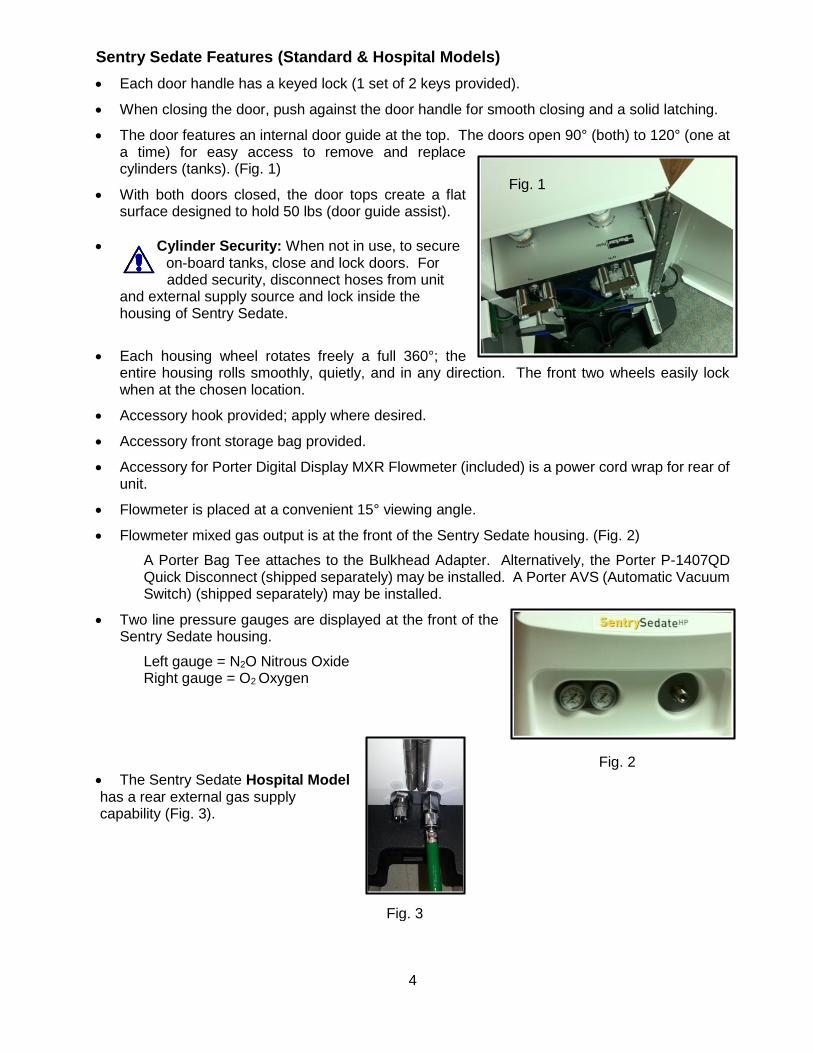
The door features an internal door guide at the top. The doors open 90° (both) to 120° (one at a time) for easy access to remove and replace cylinders (tanks). (Fig. 1)
With both doors closed, the door tops create a flat surface designed to hold 50 lbs (door guide assist).
Cylinder Security: When not in use, to secure on-board tanks, close and lock doors. For added security, disconnect hoses from unit
and external supply source and lock inside the housing of Sentry Sedate.
Each housing wheel rotates freely a full 360°; the entire housing rolls smoothly, quietly, and in any direction. The front two wheels easily lock when at the chosen location.
Accessory hook provided; apply where desired.
Accessory front storage bag provided.
Accessory for Porter Digital Display MXR Flowmeter (included) is a power cord wrap for rear of unit.
Flowmeter is placed at a convenient 15° viewing angle.
Flowmeter mixed gas output is at the front of the Sentry Sedate housing. (Fig. 2)
A Porter Bag Tee attaches to the Bulkhead Adapter. Alternatively, the Porter P-1407QD Quick Disconnect (shipped separately) may be installed. A Porter AVS (Automatic Vacuum Switch) (shipped separately) may be installed.
Two line pressure gauges are displayed at the front of the Sentry Sedate housing.
Left gauge = N2O Nitrous Oxide Right gauge = O2 Oxygen
The Sentry Sedate Hospital Model has a rear external gas supply capability (Fig. 3).
Fig. 1
Fig. 2
Fig. 3
5
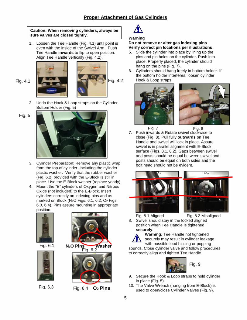
Proper Attachment of Gas Cylinders 1. Loosen the Tee Handle (Fig. 4.1) until point is
even with the inside of the Swivel Arm. Push Tee Handle inwards to flip to open position. Align Tee Handle vertically (Fig. 4.2).
2. Undo the Hook & Loop straps on the Cylinder Bottom Holder (Fig. 5)
3. Cylinder Preparation: Remove any plastic wrap from the top of cylinder, including the cylinder plastic washer. Verify that the rubber washer (Fig. 6.2) provided with the E-Block is still in place. Use the E-Block washer (replace yearly).
4. Mount the “E” cylinders of Oxygen and Nitrous Oxide (not included) to the E-Block. Insert cylinders correctly on indexing pins and as marked on Block (N2O Figs. 6.1, 6.2; O2 Figs. 6.3, 6.4). Pins assure mounting in appropriate position.
Warning Do not remove or alter gas indexing pins Verify correct pin locations per illustrations 5. Slide the cylinder into place by lining up the
pins and pin holes on the cylinder. Push into place. Properly placed, the cylinder should hang on the pins (Fig. 7).
6. Cylinders should hang freely in bottom holder. If the bottom holder interferes, loosen cylinder Hook & Loop straps.
7. Push inwards & Rotate swivel clockwise to close (Fig. 8). Pull fully outwards on Tee Handle and swivel will lock in place. Assure swivel is in parallel alignment with E-Block surface (Figs. 8.1, 8.2). Gaps between swivel and posts should be equal between swivel and posts should be equal on both sides and the bolt head should not be evident.
Fig. 8.1 Aligned Fig. 8.2 Misaligned 8. Swivel should stay in the locked aligned
position when Tee Handle is tightened securely.
Warning: Tee Handle not tightened securely may result in cylinder leakage with possible loud hissing or popping
sounds. Close cylinder valve and follow procedures to correctly align and tighten Tee Handle.
9. Secure the Hook & Loop straps to hold cylinder in place (Fig. 5).
10. The Valve Wrench (hanging from E-Block) is used to open/close Cylinder Valves (Fig. 9).
Caution: When removing cylinders, always be sure valves are closed tightly.
Fig. 7 Fig. 8
Fig. 6.4 O2 Pins
Fig. 4.1
Fig. 5
Fig. 6.1
Fig. 4.1
Fig. 9
Fig. 6.2 N2O Pins Washer
Fig. 6.3
Fig. 4.2
6
Cylinder (Tank) Operation / Maintenance Cylinder Pressure Readings: Oxygen is a true compressed gas, while in the cylinder, thus the cylinder pressure gauge can be used to determine the amount of gas remaining in the cylinder. For example, 2000 psi indicates full, 1000 psi indicates half full, etc. Nitrous Oxide is a liquefied compressed gas that vaporizes in the cylinder, thus the cylinder pressure gauge cannot be used to determine the amount of gas remaining in the cylinder until all liquid in the cylinder vaporizes. While liquid remains in the cylinder, the cylinder pressure gauge indicates the vapor pressure which depends on and varies with the temperature of the liquid. For example, at 68ºF, the vapor pressure is about 750 psi; at 20ºF, it drops to about 400 psi; while at 90ºF, it increases to about 1000 psi. After all the liquid vaporizes, the pressure will decrease normally as the gas is withdrawn, and the cylinder pressure gauge can then be used to determine the amount of gas remaining in the cylinder.
Cautions
Always turn on CYLINDER VALVES slowly and fully.
NEVER ATTEMPT TO LOOSEN cylinder valve packing nut. If valve stem is tight, return cylinder to supplier.
When operating the swivel yokes, take care not to catch or pinch fingers.
Warning: Do not remove or alter gas indexing pins
Good Practices: Cylinders with Sentry Sedate 1. Two cylinders of O2 and two cylinders of N2O are
typically connected at all times. 2. Hospital Model Exception: When using external gas
supplies of oxygen or nitrous oxide, the E-Block may be populated with one N2O cylinder and/or one O2 cylinder. Note: Attach a yoke plug in any unused cylinder locations.
3. Minimize leak risks: Confirm Yoke Washers are in
place before replacing/mounting cylinders. Use Porter #A-3399-000 replacement washers (once/yr.). Have spare washers.
4. Minimize leak risks: With cylinder in position, rotate
swivel arm and move into secure locked position when Tee Handle is tightened. To prevent movement and potential damage to yoke pins, always fasten the Hook & Loop strap restraints around cylinders.
5. Assure Sentry Sedate is populated with at least one
full cylinder of O2 and N2O before starting any procedure.
6. Label each cylinder with a tag or sticker indicating “In-Use” and “Full” (“Full” is reserve).
7. Use Cylinder Valve Wrench to open the “In-Use”
cylinders of O2 and N2O. Verify wrench is attached to E-Block.
8. Cylinder pressure gages on E-Block provide a visual
indication of cylinder status (see details on Cylinder Pressure Readings)
9. Caution: If all four cylinders (or both cylinders of one
gas) are open, the two cylinders of O2 and N2O will deplete in tandem. The “Full” cylinder will empty with the “In-Use” cylinder and will not be available as a future spare.
10. Caution: Hospital Model: If external gas supplies
are connected, any cylinders attached to the E-Block are for separate usage and are turned OFF. If cylinders are not off, they may be depleted or used up entirely, depending on the regulated pressure of the external supplies. If cylinders are to be used, disconnect the external supplies at the supply source.
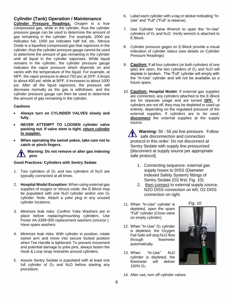
Warning: 50 - 55 psi line pressure. Follow safe disconnection and connection
protocol in this order: Do not disconnect at Sentry Sedate with supply line pressurized [disconnect at supply source per appropriate safe protocol].
1. Connecting sequence: external gas supply hoses to DISS (Diameter Indexed Safety System) fittings of Sentry Sedate (O2 first; Fig. 10);
2. then connect to external supply source. N2O DISS connection on left; O2 DISS connection on right.
11. When “In-Use” cylinder is
depleted, open the spare “Full” cylinder (Close valve on empty cylinder).
12. When “In-Use” O2 cylinder
is depleted, the Oxygen Fail Safe will stop N2O flow through flowmeter automatically.
13. When “In-Use” N2O
cylinder is depleted, the flowmeter will deliver 100% O2.
14. After use, turn off cylinder valves.
Fig. 10
7
Sentry Sedate Operation – Standard Model
Connections from Flowmeter to Gas Supply
1. Verify hoses and DISS connections internal to Sentry Sedate are attached and tight from Flowmeter to E-Block.
2. Attach Cylinders. Follow cylinder Good Practices.
3. Open one each O2 and N2O Cylinder Valves with wrench provided.
4. Observe cylinder pressures. Replace cylinder when less than 300 psi, at room temperature (21.1 ºC, 70ºF). During replacement, close all Cylinder Valves.
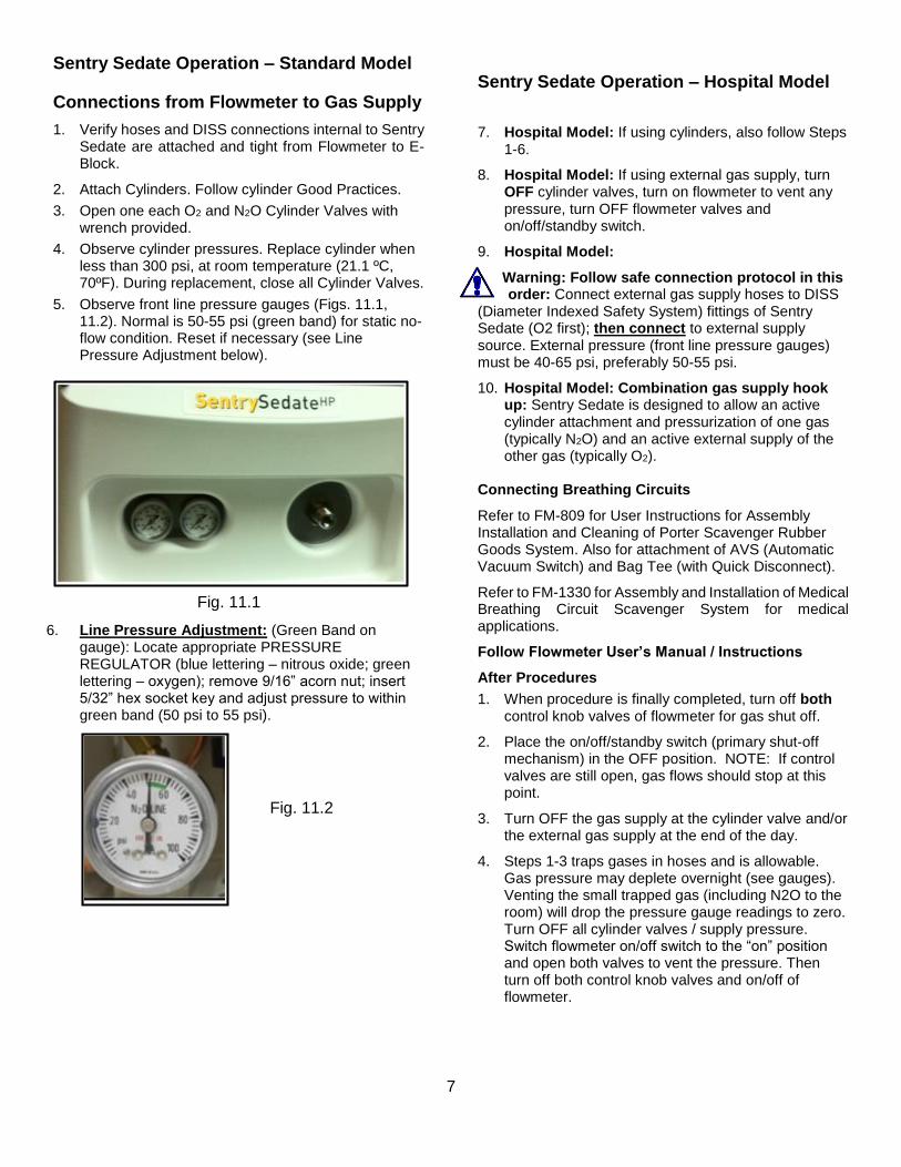
5. Observe front line pressure gauges (Figs. 11.1, 11.2). Normal is 50-55 psi (green band) for static no-flow condition. Reset if necessary (see Line Pressure Adjustment below).
6. Line Pressure Adjustment: (Green Band on gauge): Locate appropriate PRESSURE REGULATOR (blue lettering – nitrous oxide; green lettering – oxygen); remove 9/16” acorn nut; insert 5/32” hex socket key and adjust pressure to within green band (50 psi to 55 psi).
Sentry Sedate Operation – Hospital Model
7. Hospital Model: If using cylinders, also follow Steps 1-6.
8. Hospital Model: If using external gas supply, turn OFF cylinder valves, turn on flowmeter to vent any pressure, turn OFF flowmeter valves and on/off/standby switch.
9. Hospital Model:
Warning: Follow safe connection protocol in this order: Connect external gas supply hoses to DISS
(Diameter Indexed Safety System) fittings of Sentry Sedate (O2 first); then connect to external supply source. External pressure (front line pressure gauges) must be 40-65 psi, preferably 50-55 psi.
10. Hospital Model: Combination gas supply hook up: Sentry Sedate is designed to allow an active cylinder attachment and pressurization of one gas (typically N2O) and an active external supply of the other gas (typically O2).
Connecting Breathing Circuits
Refer to FM-809 for User Instructions for Assembly Installation and Cleaning of Porter Scavenger Rubber Goods System. Also for attachment of AVS (Automatic Vacuum Switch) and Bag Tee (with Quick Disconnect).
Refer to FM-1330 for Assembly and Installation of Medical Breathing Circuit Scavenger System for medical applications.
Follow Flowmeter User’s Manual / Instructions
After Procedures
1. When procedure is finally completed, turn off both control knob valves of flowmeter for gas shut off.
2. Place the on/off/standby switch (primary shut-off mechanism) in the OFF position. NOTE: If control valves are still open, gas flows should stop at this point.
3. Turn OFF the gas supply at the cylinder valve and/or the external gas supply at the end of the day.
4. Steps 1-3 traps gases in hoses and is allowable. Gas pressure may deplete overnight (see gauges). Venting the small trapped gas (including N2O to the room) will drop the pressure gauge readings to zero. Turn OFF all cylinder valves / supply pressure. Switch flowmeter on/off switch to the “on” position and open both valves to vent the pressure. Then turn off both control knob valves and on/off of flowmeter.
Fig. 11.2
Fig. 11.1
8
Initial and Monthly Check – Standard Model (without external gas supplies feature):
Sentry Sedate internal verification. Leak test the entire system for working pressure leaks.
1. Primary Leak Test: Attach a tank to one of two N2O
E-Block yoke connections. Alternate positions monthly [test of check valve in E-Block].
2. With flowmeter valves closed and the on/off switch in the off/standby position, open the tank valve.
3. Verify that both N2O gauges [tank & line] are indicating pressure and there is no pressure being indicated on the O2 gauges. Also verify that the low pressure N2O gauge [front; line] is indicating 53 +/- 2 PSIG. Reset if necessary (see Line Pressure Adjustment Procedure).
4. Turn the flowmeter on and open the O2 and N2O valves. There should be no flow exiting the flowmeter (check the bulkhead connection in front).
5. Attach a tank to one of two O2 E-Block yoke connections. Alternate positions monthly [test of check valve in E-Block].
6. Open the tank valve. 7. Verify that both O2 gauges are indicating pressure
and there is flow exiting the flowmeter bulkhead connector. Verify flow through both flowmeter rotameters.
8. Switch flowmeter on/off switch to the off/standby position. Verify that the low pressure O2 gauge is indicating 53 +/- 2 PSIG. Reset if necessary (see Line Pressure Adjustment Procedure).
9. Apply masking tape to both gauge faces. Tap lightly on gauges and mark gauge needle positions on the masking tape. Do this to both front gauges and both tank gauges.
10. Turn off both tanks and wait 15 minutes. There should be little or no movement in the pressure gauge needles.
11. If there is excessive needle movement in a gauge, repair the leak and retest. Verify hoses and DISS connections internal to Sentry Sedate are attached and tight from Flowmeter to E-Block. At connections, bubbles will appear at leaking locations when a soap/water solution is used.
12. If no leaks are found, switch flowmeter on/off switch to the “on” position to vent the pressure.
Initial and Monthly Check – Hospital Model (with external gas supplies feature):
Note: This test is in addition and is entirely separate from crossed line verification of the central gas supply
lines. This test is a Sentry Sedate internal verification leak test of the entire system for working pressure leaks.
1. Primary Leak Test: Conduct the same Leak Test
(Steps 1 – 12) of the Standard Model. [For Hospital Model this test checks two check valves of external hose assembly / Gauge Block.]
2. Secondary Leak Test: With pressure vented from the unit after Primary Leak Test, connect an N2O external supply line to the rear N2O DISS connection. [Checks one check valve in Gauge Block]
3. With both flowmeter valves closed and the on/off switch in the off/standby position, pressurize the N2O supply line [40 to 65 psi, preferably 50 to 55 psi].
4. Verify that the N2O gauge [front; line] is indicating pressure and there is no pressure being indicated in the O2 gauge.
5. Turn the flowmeter on and open the O2 and N2O valves. There should be no flow exiting the flowmeter (check the bulkhead connection).
6. Connect an O2 external supply line to the rear O2
DISS connection and pressurize the O2 supply line [40 to 65 psi, preferably 50 to 55 psi]. [Checks second check valve in Gauge Block]
7. Verify tank pressure gauges of E-Block read zero. 8. Verify that the O2 gauge is indicating pressure and
there is flow exiting the flowmeter bulkhead connector. Verify flow through both flowmeter rotameters.
9. Switch flowmeter on/off switch to the off/standby position, turn off the supply pressures to the rear of the unit, and mark the needle locations on both front gauges. Wait 15 minutes. A 5 psi drop is allowable.
10. If there is excessive needle movement in a gauge, repair the leak and retest. (See Standard Model Step 11).
11. If no leaks are found, switch flowmeter on/off switch to the “on” position to vent the pressure.
9
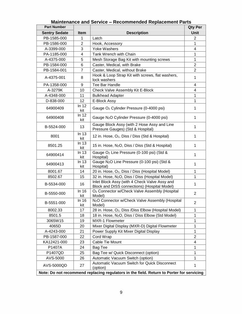
Maintenance and Service – Recommended Replacement Parts Part Number Qty Per
Sentry Sedate Item Description Unit
PB-1585-000 1 Latch 2
PB-1586-000 2 Hook, Accessory 1
A-3399-000 3 Yoke Washers 4
PA-1185-000 4 Tank Wrench with Chain 1
A-4375-000 5 Mesh Storage Bag Kit with mounting screws 1
PB-1584-000 6 Caster, Medical, with Brake 2
PB-1584-001 7 Caster, Medical, without Brake 2
A-4375-001 8 Hook & Loop Strap Kit with screws, flat washers, lock washers
1
PA-1358-000 9 Tee Bar Handle 4
A-3279K 10 Check Valve Assembly Kit E-Block 4
A-4348-000 11 Bulkhead Adapter 1
D-838-000 12 E-Block Assy 1
64900409 In 12
kit Gauge O2 Cylinder Pressure (0-4000 psi) 1
64900408 In 12
kit Gauge N2O Cylinder Pressure (0-4000 psi) 1
B-5524-000 13 Gauge Block Assy (with 2 Hose Assy and Line Pressure Gauges) (Std & Hospital)
1
8001 In 13
kit 12 in. Hose, O2, Diss / Diss (Std & Hospital) 1
8501.25 In 13
kit 15 in. Hose, N2O, Diss / Diss (Std & Hospital) 1
64900414 In 13
kit Gauge O2 Line Pressure (0-100 psi) (Std & Hospital)
1
64900413 In 13
kit Gauge N2O Line Pressure (0-100 psi) (Std & Hospital)
1
8001.67 14 20 in. Hose, O2, Diss / Diss (Hospital Model) 1
8502.67 15 32 in. Hose, N2O, Diss / Diss (Hospital Model) 1
B-5534-000 16 Inlet Block Assy (with 4 Check Valve Assy and Block and DISS connections) (Hospital Model)
1
B-5550-000 In 16
kit O2 Connector w/Check Valve Assembly (Hospital Model)
2
B-5551-000 In 16
kit N2O Connector w/Check Valve Assembly (Hospital Model)
2
8002.33 17 28 in. Hose, O2, Diss /Diss Elbow (Hospital Model) 1
8501.5 18 18 in. Hose, N2O, Diss / Diss Elbow (Std Model) 1
3065W15 19 MXR-1 Flowmeter 1
4065D 20 Mixer Digital Display (MXR-D) Digital Flowmeter 1
A-4243-000 21 Power Supply Kit Mixer Digital Display 1
PB-1587-000 22 Cord Wrap 2
KA12421-000 23 Cable Tie Mount 4
P1407A 24 Bag Tee 1
P1407QD 25 Bag Tee w/ Quick Disconnect (option) 1
AVS-5000 26 Automatic Vacuum Switch (option) 1
AVS-5000QD 27 Automatic Vacuum Switch for Quick Disconnect (option)
1
Note: Do not recommend replacing regulators in the field. Return to Porter for servicing
10
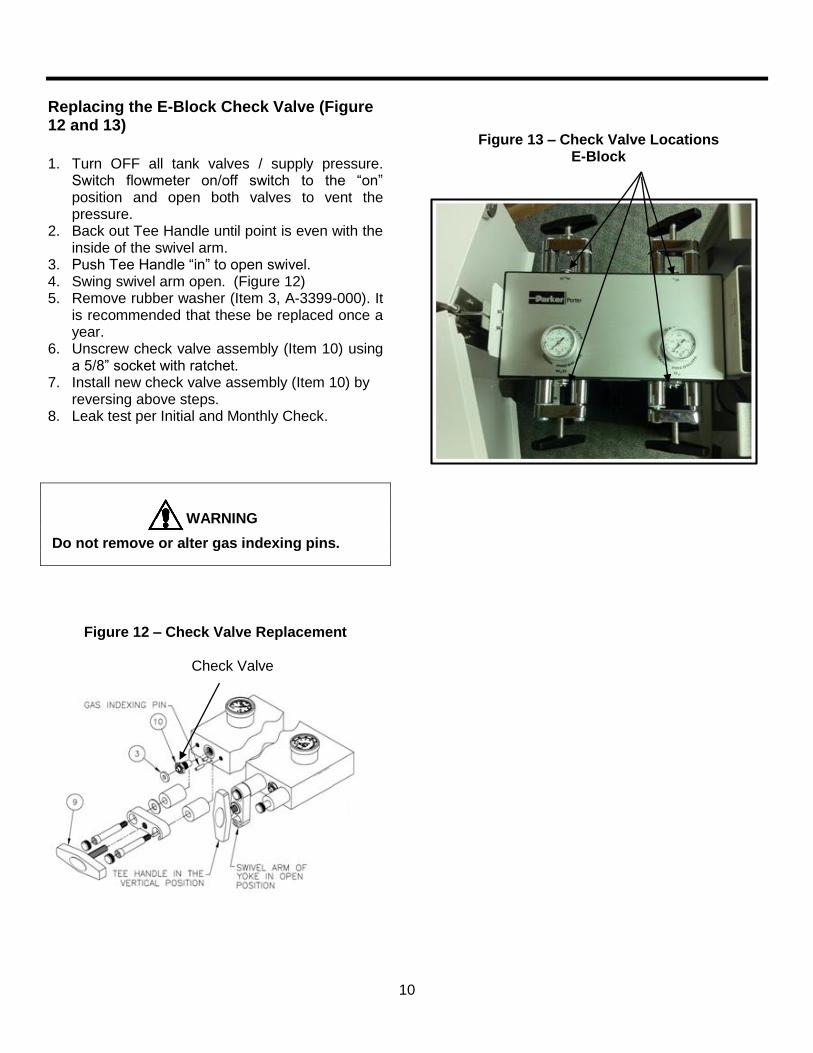
Replacing the E-Block Check Valve (Figure 12 and 13)
1. Turn OFF all tank valves / supply pressure.
Switch flowmeter on/off switch to the “on” position and open both valves to vent the pressure.
2. Back out Tee Handle until point is even with the inside of the swivel arm.
3. Push Tee Handle “in” to open swivel. 4. Swing swivel arm open. (Figure 12) 5. Remove rubber washer (Item 3, A-3399-000). It
is recommended that these be replaced once a year.
6. Unscrew check valve assembly (Item 10) using a 5/8” socket with ratchet.
7. Install new check valve assembly (Item 10) by reversing above steps.
8. Leak test per Initial and Monthly Check.
WARNING
Do not remove or alter gas indexing pins.
Figure 12 – Check Valve Replacement
Check Valve
Figure 13 – Check Valve Locations E-Block
11
E-Block Cylinder Pressure Gauge Replacement
Warning: High pressure (up to 2400 psi). Turn OFF all tank valves / supply pressure.
Switch flowmeter on/off switch to the “on” position and open both valves to vent the pressure. 1. Unscrew the pressure gauge. 2. Install new pressure gauge; verify PTFE tape is
applied to the NPT thread; tighten carefully so as not to cross thread with the E-Block cavity.
3. Close the Sentry Sedate door over the new pressure gauge location.
4. Turn on tank valve slowly at location of the open door.
5. Leak test per Initial and Monthly Check.
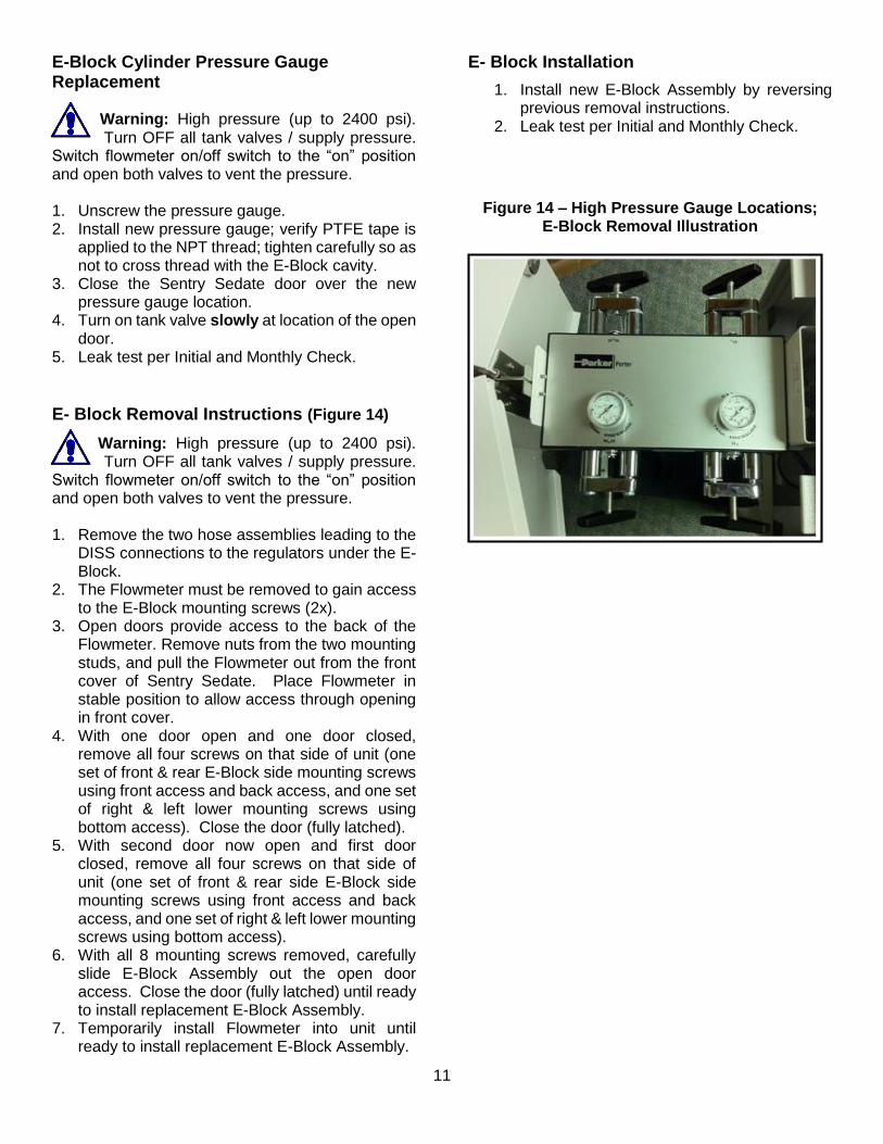
E- Block Removal Instructions (Figure 14)
Warning: High pressure (up to 2400 psi). Turn OFF all tank valves / supply pressure.
Switch flowmeter on/off switch to the “on” position and open both valves to vent the pressure. 1. Remove the two hose assemblies leading to the
DISS connections to the regulators under the E-Block.
2. The Flowmeter must be removed to gain access to the E-Block mounting screws (2x).
3. Open doors provide access to the back of the Flowmeter. Remove nuts from the two mounting studs, and pull the Flowmeter out from the front cover of Sentry Sedate. Place Flowmeter in stable position to allow access through opening in front cover.
4. With one door open and one door closed, remove all four screws on that side of unit (one set of front & rear E-Block side mounting screws using front access and back access, and one set of right & left lower mounting screws using bottom access). Close the door (fully latched).
5. With second door now open and first door closed, remove all four screws on that side of unit (one set of front & rear side E-Block side mounting screws using front access and back access, and one set of right & left lower mounting screws using bottom access).
6. With all 8 mounting screws removed, carefully slide E-Block Assembly out the open door access. Close the door (fully latched) until ready to install replacement E-Block Assembly.
7. Temporarily install Flowmeter into unit until ready to install replacement E-Block Assembly.
E- Block Installation
1. Install new E-Block Assembly by reversing previous removal instructions.
2. Leak test per Initial and Monthly Check.
Figure 14 – High Pressure Gauge Locations; E-Block Removal Illustration
12
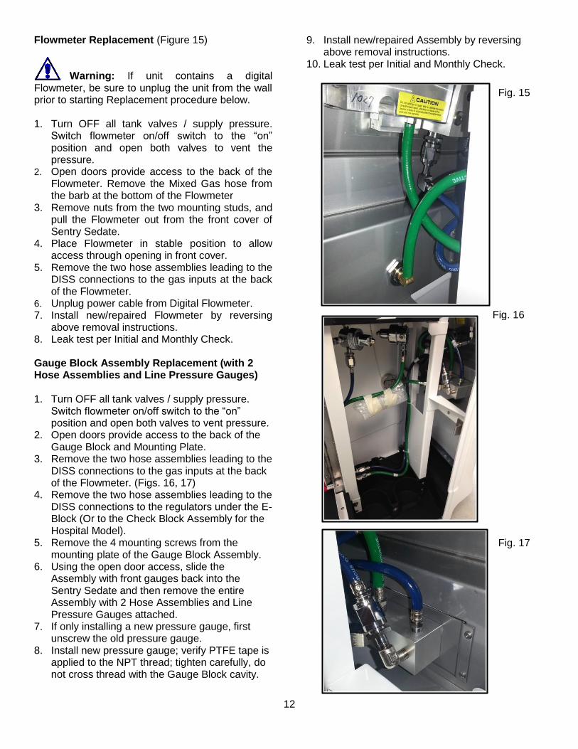
Flowmeter Replacement (Figure 15)
Warning: If unit contains a digital
Flowmeter, be sure to unplug the unit from the wall prior to starting Replacement procedure below. 1. Turn OFF all tank valves / supply pressure.
Switch flowmeter on/off switch to the “on” position and open both valves to vent the pressure.
2. Open doors provide access to the back of the Flowmeter. Remove the Mixed Gas hose from the barb at the bottom of the Flowmeter
3. Remove nuts from the two mounting studs, and pull the Flowmeter out from the front cover of Sentry Sedate.
4. Place Flowmeter in stable position to allow access through opening in front cover.
5. Remove the two hose assemblies leading to the DISS connections to the gas inputs at the back of the Flowmeter.
6. Unplug power cable from Digital Flowmeter. 7. Install new/repaired Flowmeter by reversing
above removal instructions. 8. Leak test per Initial and Monthly Check. Gauge Block Assembly Replacement (with 2 Hose Assemblies and Line Pressure Gauges) 1. Turn OFF all tank valves / supply pressure.
Switch flowmeter on/off switch to the “on” position and open both valves to vent pressure.
2. Open doors provide access to the back of the Gauge Block and Mounting Plate.
3. Remove the two hose assemblies leading to the DISS connections to the gas inputs at the back of the Flowmeter. (Figs. 16, 17)
4. Remove the two hose assemblies leading to the DISS connections to the regulators under the E-Block (Or to the Check Block Assembly for the Hospital Model).
5. Remove the 4 mounting screws from the mounting plate of the Gauge Block Assembly.
6. Using the open door access, slide the Assembly with front gauges back into the Sentry Sedate and then remove the entire Assembly with 2 Hose Assemblies and Line Pressure Gauges attached.
7. If only installing a new pressure gauge, first unscrew the old pressure gauge.
8. Install new pressure gauge; verify PTFE tape is applied to the NPT thread; tighten carefully, do not cross thread with the Gauge Block cavity.
9. Install new/repaired Assembly by reversing above removal instructions.
10. Leak test per Initial and Monthly Check.
Fig. 15
Fig. 16
Fig. 17
13
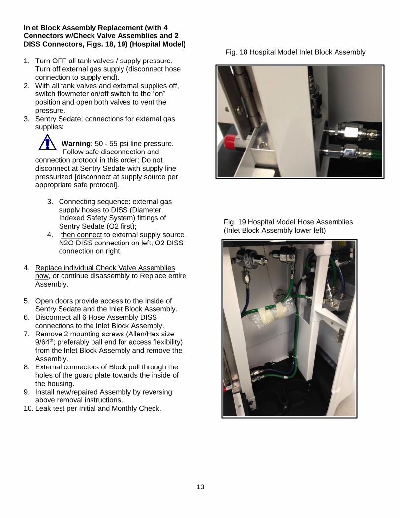
Inlet Block Assembly Replacement (with 4 Connectors w/Check Valve Assemblies and 2 DISS Connectors, Figs. 18, 19) (Hospital Model) 1. Turn OFF all tank valves / supply pressure.
Turn off external gas supply (disconnect hose connection to supply end).
2. With all tank valves and external supplies off, switch flowmeter on/off switch to the “on” position and open both valves to vent the pressure.
3. Sentry Sedate; connections for external gas supplies:
Warning: 50 - 55 psi line pressure. Follow safe disconnection and
connection protocol in this order: Do not disconnect at Sentry Sedate with supply line pressurized [disconnect at supply source per appropriate safe protocol].
3. Connecting sequence: external gas supply hoses to DISS (Diameter Indexed Safety System) fittings of Sentry Sedate (O2 first);
4. then connect to external supply source. N2O DISS connection on left; O2 DISS connection on right.
4. Replace individual Check Valve Assemblies
now, or continue disassembly to Replace entire Assembly.
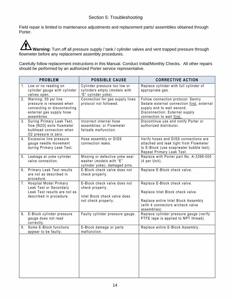
5. Open doors provide access to the inside of
Sentry Sedate and the Inlet Block Assembly. 6. Disconnect all 6 Hose Assembly DISS
connections to the Inlet Block Assembly. 7. Remove 2 mounting screws (Allen/Hex size
9/64th; preferably ball end for access flexibility) from the Inlet Block Assembly and remove the Assembly.
8. External connectors of Block pull through the holes of the guard plate towards the inside of the housing.
9. Install new/repaired Assembly by reversing above removal instructions.
10. Leak test per Initial and Monthly Check.
Fig. 18 Hospital Model Inlet Block Assembly
Fig. 19 Hospital Model Hose Assemblies (Inlet Block Assembly lower left)
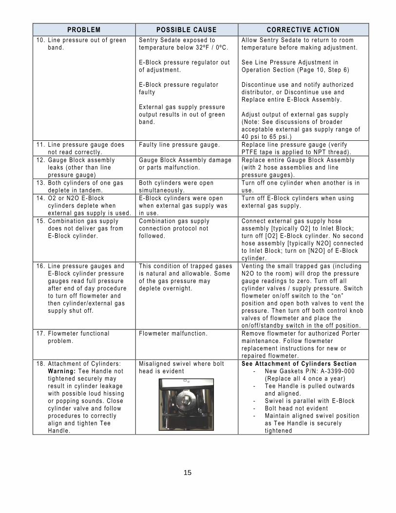
Section 5: Troubleshooting Field repair is limited to maintenance adjustments and replacement parts/ assemblies obtained through Porter.
Warning: Turn off all pressure supply / tank / cylinder valves and vent trapped pressure through flowmeter before any replacement assembly procedures. Carefully follow replacement instructions in this Manual. Conduct Initial/Monthly Checks. All other repairs should be performed by an authorized Porter service representative.
PROBLEM POSSIBLE CAUSE CORRECTIVE ACTION
1. Low or no read ing on cy l inder gauge w i th cy l inder va l ves open .
Cy l i nder p ressure too l ow or cy l inders empty (mode ls w i th “E ” cy l i nde r yoke) .
Rep lace cy l i nde r w i th f u l l cy l inder o f appropr ia te gas.
2 . Warn ing: 50 ps i l i ne pressure i s r e leased when connec t ing or d isconnect ing ex terna l gas supp ly hose assemb l ies .
Connect ion fo r gas supp ly l i nes pro toco l no t fo l l owed.
Fo l l ow connec t ion pro toco l : Sent r y Sedate ex te rna l connect ion f i rs t , ex terna l supp ly end to wa l l second. D isconnect ion : Externa l supp ly connec t ion to wa l l f i r s t .
3 . Dur ing Pr imary Leak Tes t , f low [N2O] ex i t s f lowmeter bu lkhead connect ion when O2 pressure is zero .
Incor rec t in te rna l hose assemb l ies ; o r F lowmeter fa i lsa fe ma l func t ion .
D iscont inue use and not i fy Por te r o r au thor i zed d is t r ibu to r .
4 . Excess ive l ine pressure gauge need le movement dur ing Pr imary Leak Tes t .
Hose assembly or D ISS connec t ion leaks .
Ver i f y hoses and D ISS connect ions are a t tached and leak t i gh t f r om F lowmete r to E-Block (use soap /wate r bubb le tes t ) . Repeat Pr imary Leak Test .
5 . Leakage a t yoke cy l inder va l ve connect ion .
M iss ing or de fec t ive yoke sea l washer (mode ls w i th “E” cy l inder yoke) ; damaged p ins .
Rep lace w i th Por ter par t No. A -3399-000 (4 pe r Un i t ) .
6 . Pr imary Leak Test resu l ts a re not as descr ibed in procedure .
E-Block check va l ve does not check proper ly .
Rep lace E-B lock check va l ve .
7 . Hosp i ta l Mode l Pr imary Leak Test o r Secondary Leak Test resu l ts a re no t as descr ibed in procedure .
E-Block check va l ve does not check proper ly . In le t B lock check va l ve does not check proper ly .
Rep lace E-B lock check va l ve . Rep lace In le t B lock check va l ve . Rep lace ent i re In le t B lock Assembly (w i th 4 connec tor s w/check va l ve assemb l ies)
8 . E-Block cy l i nder p ressure gauge does not r ead cor rec t ly .
Fau l ty cy l inder p ressure gauge . Rep lace cy l i nde r p ressure gauge ( ver i f y PTFE tape is app l i ed to NPT thread) .
9 . Some E-B lock funct ions appear t o be fau l t y .
E-Block damage or par t s mal funct ion .
Rep lace ent i re E -Block Assemb ly .
144
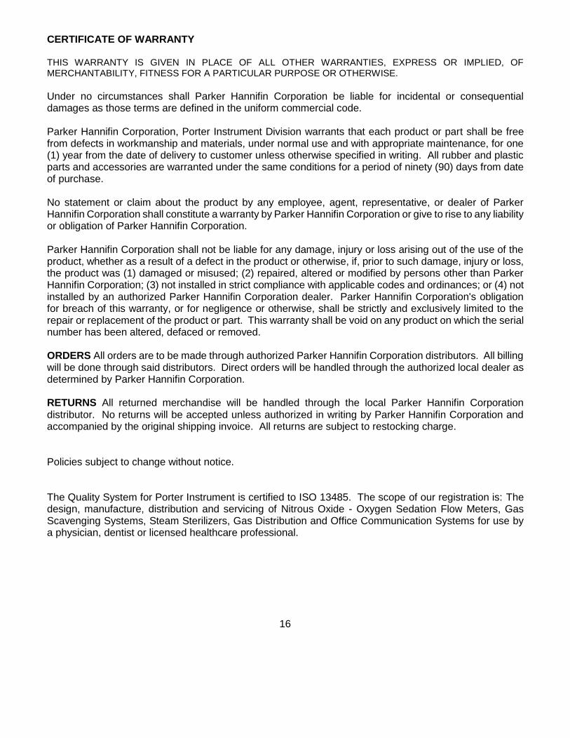
PROBLEM POSSIBLE CAUSE CORRECTIVE ACTION
10. L ine pressure ou t o f g reen band .
Sent r y Sedate exposed to tempera ture be low 32ºF / 0ºC . E-Block p ressure regu la to r ou t o f ad jus tmen t . E-Block p ressure regu la to r fau l ty Ex terna l gas supp ly pressure output r esu l ts in ou t o f g reen band .
A l low Sent r y Sedate to r e turn to r oom tempera ture be fore mak ing ad jus tment . See L ine Pressure Ad jus tment in Opera t ion Sec t ion (Page 10, Step 6) D iscont inue use and not i fy au thor ized d is t r i bu tor , o r D iscont inue use and Rep lace ent i re E -Block Assemb ly . Ad jus t ou tput o f ex terna l gas supp ly (Note : See d i scuss ions o f b roader acceptab le ex terna l gas supp ly r ange o f 40 ps i to 65 ps i . )
11 . L ine pressure gauge does not r ead cor rec t ly .
Fau l ty l i ne pressure gauge . Rep lace l i ne pressure gauge ( ver i fy PTFE tape is app l i ed to NPT thread) .
12 . Gauge B lock assembly leaks (o ther than l ine pressure gauge)
Gauge B lock Assemb ly damage or pa r ts ma l func t ion .
Rep lace ent i re Gauge Block Assemb ly (w i th 2 hose assemb l ies and l ine pressure gauges) .
13 . Both cy l i nders o f one gas dep le te i n t andem.
Bo th cy l i nders were open s imul taneous ly .
Turn o f f one cy l inder when ano ther i s in use .
14 . O2 or N2O E-Block cy l inders dep le te when ex terna l gas supp ly i s used.
E-Block cy l i nders were open when ex terna l gas supp ly was in use .
Turn o f f E -B lock cy l inders when us ing ex terna l gas supp ly .
15 . Combinat ion gas supp ly does not de l iver gas f r om E-Block cy l i nder .
Combinat ion gas supp ly connec t ion pro toco l no t fo l lowed .
Connect ex terna l gas supp ly hose assemb ly [ t yp ica l ly O2 ] t o In le t B lock ; tu rn o f f [O2] E -Block cy l inder . No second hose assemb ly [ t yp ica l l y N2O] connected to I n le t B lock ; tu rn on [N2O] o f E -B lock cy l inder .
16 . L ine pressure gauges and E-Block cy l i nder p ressu re gauges read fu l l p ressure a f te r end o f day procedure to t u rn o f f f lowmeter and then cy l inder /ex terna l gas supp ly shut o f f .
Th is cond i t ion o f t rapped gases is na tura l and a l lowab le . Some o f t he gas pressure may dep le te overn igh t .
Vent ing the smal l t rappe d gas ( inc lud ing N2O to the room) w i l l d rop the pressure gauge read ings to zero . Turn o f f a l l cy l inder va lves / supp ly pressure . Sw i t ch f lowmeter on /o f f sw i tch to the “on ” pos i t ion and open bo th va l ves to vent the pressure . Then tu rn o f f bo th con t ro l knob va lves o f f lowmeter and p lace the on/o f f / s tandby swi t ch i n t he o f f pos i t ion .
17 . Flowmeter funct iona l p rob lem.
F lowmeter mal funct ion . Remove f lowmeter fo r au thor i zed Por ter main tenance. Fo l low f l owmeter rep lacemen t ins t ruc t ions fo r new or repa i red f lowmeter .
18 . At tachment o f Cy l inders : Warn ing: Tee Hand le not t igh tened secure l y may resu l t in cy l inder leakage wi th poss ib le l oud h iss ing or popp ing sounds. C lose cy l inder va lve and fo l low procedures to co r rec t l y a l i gn and t igh ten Tee Hand le .
M isa l igned swive l where bo l t head i s ev iden t
See At tachment of Cyl inders Sect ion - New Gaske ts P /N : A -3399-000
(Rep lace a l l 4 once a year ) - Tee Hand le i s pu l led outwards
and a l igned. - Swive l i s para l l e l w i th E -B lock - Bo l t head not ev ident - Main ta in a l igned swive l pos i t ion
as Tee Hand le is secure l y t igh tened
15
4
CERTIFICATE OF WARRANTY THIS WARRANTY IS GIVEN IN PLACE OF ALL OTHER WARRANTIES, EXPRESS OR IMPLIED, OF MERCHANTABILITY, FITNESS FOR A PARTICULAR PURPOSE OR OTHERWISE.
Under no circumstances shall Parker Hannifin Corporation be liable for incidental or consequential damages as those terms are defined in the uniform commercial code. Parker Hannifin Corporation, Porter Instrument Division warrants that each product or part shall be free from defects in workmanship and materials, under normal use and with appropriate maintenance, for one (1) year from the date of delivery to customer unless otherwise specified in writing. All rubber and plastic parts and accessories are warranted under the same conditions for a period of ninety (90) days from date of purchase. No statement or claim about the product by any employee, agent, representative, or dealer of Parker Hannifin Corporation shall constitute a warranty by Parker Hannifin Corporation or give to rise to any liability or obligation of Parker Hannifin Corporation. Parker Hannifin Corporation shall not be liable for any damage, injury or loss arising out of the use of the product, whether as a result of a defect in the product or otherwise, if, prior to such damage, injury or loss, the product was (1) damaged or misused; (2) repaired, altered or modified by persons other than Parker Hannifin Corporation; (3) not installed in strict compliance with applicable codes and ordinances; or (4) not installed by an authorized Parker Hannifin Corporation dealer. Parker Hannifin Corporation's obligation for breach of this warranty, or for negligence or otherwise, shall be strictly and exclusively limited to the repair or replacement of the product or part. This warranty shall be void on any product on which the serial number has been altered, defaced or removed. ORDERS All orders are to be made through authorized Parker Hannifin Corporation distributors. All billing will be done through said distributors. Direct orders will be handled through the authorized local dealer as determined by Parker Hannifin Corporation. RETURNS All returned merchandise will be handled through the local Parker Hannifin Corporation distributor. No returns will be accepted unless authorized in writing by Parker Hannifin Corporation and accompanied by the original shipping invoice. All returns are subject to restocking charge. Policies subject to change without notice. The Quality System for Porter Instrument is certified to ISO 13485. The scope of our registration is: The design, manufacture, distribution and servicing of Nitrous Oxide - Oxygen Sedation Flow Meters, Gas Scavenging Systems, Steam Sterilizers, Gas Distribution and Office Communication Systems for use by a physician, dentist or licensed healthcare professional.
16