separation of data and control planes - wireless@kth · separation of data and control 5 lte user...
TRANSCRIPT

Separation of data and control planes
Haibin ZhangSenior scientist
5Green Summer SchoolKTH, Sweden28 August 2014

Table of content
� Introduction
� Concept of separating user and control planes
� Modelling of control signalling traffic
� Impact to the design of key network functions
� Q&A
August 18, 2014Haibin ZhangSeparation of data and control
2

Introduction
August 18, 2014Haibin ZhangSeparation of data and control
3

Background
� Energy costs of mobile networks are increasing with the increase of
network capacity, and in some cases (e.g. in emerging markets)
even account for ~30% of operators OPEX
� Energy saving may be achieved via various ways
� Improve hardware efficiency
� Green transmission techniques (e.g. massive MIMO)
� Network management (e.g. dynamic switching-off/on, large- and small-scale)
� Network deployment (e.g. network sharing, radio planning)
� Network architecture (e.g. HetNet, user/control-plane separation)
� Example results-> [1]
August 18, 2014Haibin ZhangSeparation of data and control
4
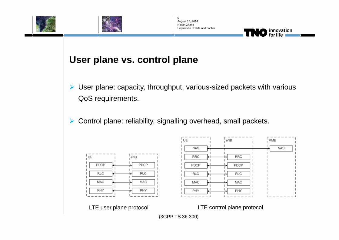
User plane vs. control plane
� User plane: capacity, throughput, various-sized packets with various
QoS requirements.
� Control plane: reliability, signalling overhead, small packets.
August 18, 2014Haibin ZhangSeparation of data and control
5
LTE user plane protocol LTE control plane protocol
(3GPP TS 36.300)

Limits of legacy mobile networks
� User plane and control plane are coupled (via the same cell)
� A significant part of the network (coverage layer) needs to be “always
on”, even at very low traffic load.
� Network-based energy saving (switching off cells) is applicable, but
at relatively large time scale.
August 18, 2014Haibin ZhangSeparation of data and control
6

Concept of separating user and control planes
August 18, 2014Haibin ZhangSeparation of data and control
7

Concept in brief
August 18, 2014Haibin ZhangSeparation of data and control
8
Control plane (signalling)
User plane (data)
Conventional cell
signallingdata
Signalling cellData cell
Conventional network: Data and control signalling are served by a single cell. Coverage and capacity are always available.
User/control plane separation: Data and control signalling are served by different cells. Coverage is always available, but capacity is activated on-demand.

Status
� 5GrEEn
� GreenTouch Beyond Cellular Green Generation (BCG2) project
� 3GPP new-carrier type (NCT)- (not standardised yet)
� For lower overhead, interference and energy usage
� More options of system bandwidths.
� Stand-alone (new frequency band), or Macro-assisted
� Similar concepts: Phantom cell (NTT DoCoMo), Soft-cell (Ericsson),
etc.
August 18, 2014Haibin ZhangSeparation of data and control
9
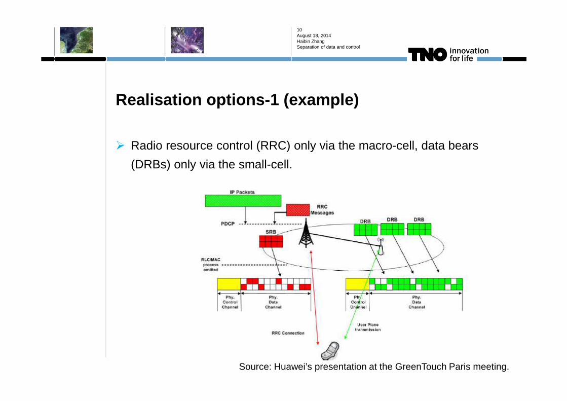
Realisation options-1 (example)
� Radio resource control (RRC) only via the macro-cell, data bears
(DRBs) only via the small-cell.
August 18, 2014Haibin ZhangSeparation of data and control
10
Source: Huawei’s presentation at the GreenTouch Paris meeting.
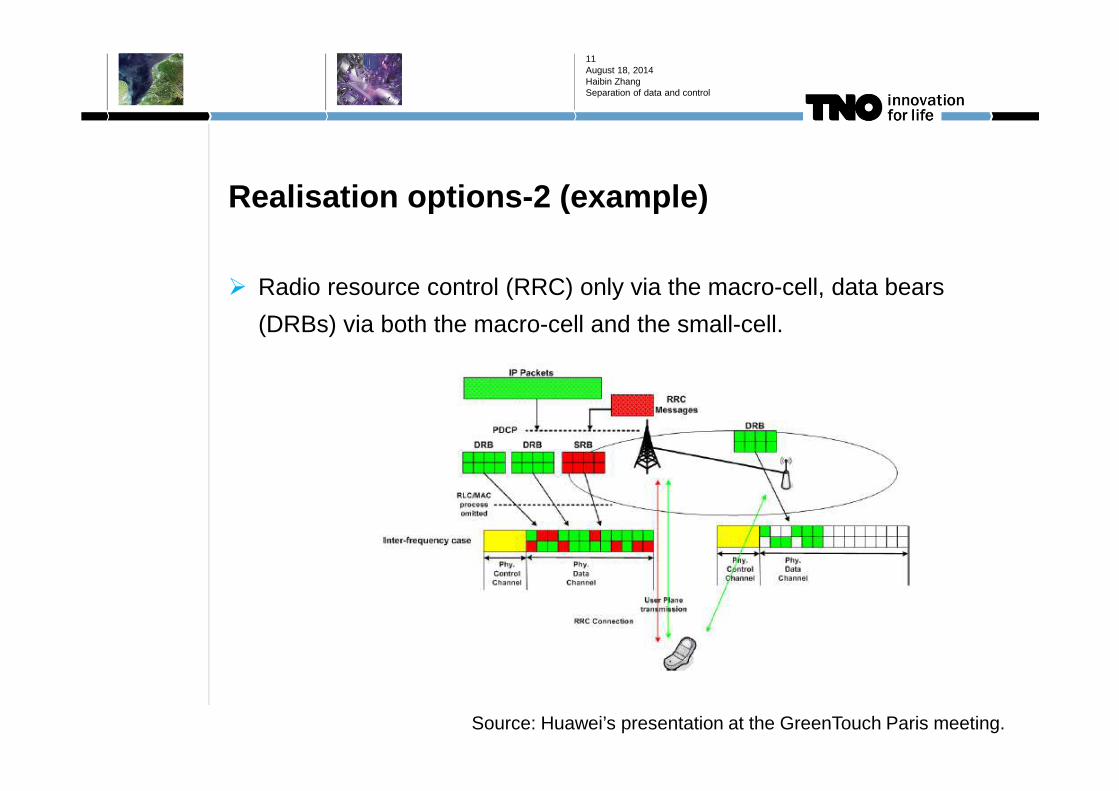
Realisation options-2 (example)
� Radio resource control (RRC) only via the macro-cell, data bears
(DRBs) via both the macro-cell and the small-cell.
August 18, 2014Haibin ZhangSeparation of data and control
11
Source: Huawei’s presentation at the GreenTouch Paris meeting.

Realisation options-3 (example)
� Radio resource control (RRC) and data bears (DRBs) via both the
macro-cell and the small-cell.
� Idle UEs vs. active UEs
� Control signal for active UE mobility may be via the small-cell.
August 18, 2014Haibin ZhangSeparation of data and control
12
Source: Huawei’s presentation at the GreenTouch Paris meeting.
Essence of being more energy efficient
� Dynamic switching on/off radio resources according to varying traffic
demands.
� Dynamically switching on (off) data cells at events of traffic arrivals
(departures)
� data cell selection is inherently a part of session setup, while not in legacy networks.
� enabled by context-awareness.
� highly bursty load per data cell.
� The “always on” part (the signalling cell) is expected to be a relatively
“light-weight” layer than that in legacy HetNet networks with energy
saving feature.
� Dimensioned for control signalling plus eventual limited amount of data traffic.
August 18, 2014Haibin ZhangSeparation of data and control
13

Essence of being more energy efficient (cont.)
� The “on-demand” part (the data cells) is with lower signalling
overhead, especially at low and medium load.
� Reduction of “fixed” signalling overhead, interference
� With lower traffic variation in the cells, a better operation point
(especially of power amplifiers) might be realized with higher energy-
efficiency.
August 18, 2014Haibin ZhangSeparation of data and control
14
Source: GreenTouch BCG2 project

Modelling of control signalling traffic
August 18, 2014Haibin ZhangSeparation of data and control
15
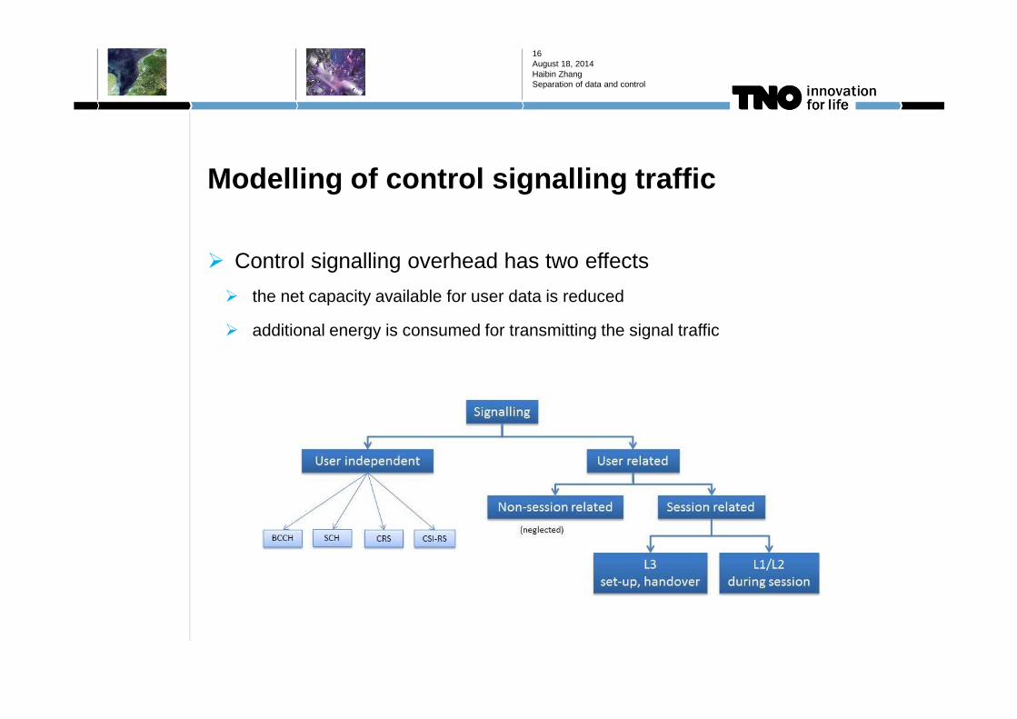
Modelling of control signalling traffic
� Control signalling overhead has two effects
� the net capacity available for user data is reduced
� additional energy is consumed for transmitting the signal traffic
August 18, 2014Haibin ZhangSeparation of data and control
16

Modelling of control signalling traffic
� User independent L1/L2 signals and common controls
August 18, 2014Haibin ZhangSeparation of data and control
17
BCCH/PBCH: Broadcast control channel/Physical broadcast channel; SCH/SS: Synchronisation channel/Synchronisation signalCRS: Cell-specific reference signal (LTE Rel-8);CSI-RS: Channel state information-reference signal (LTE Rel-10) (LTE as example)
CRSPBCH+SCH
CSI-RS
(3GPP TS 36.211)[2]

Modelling of control signalling traffic
� User independent L1/L2 signals and common controls (continued)
� modelled as fixed overhead (in percentage) of the total resources available
August 18, 2014Haibin ZhangSeparation of data and control
18
PBCH+SCH
Signals/common control channels 1 port 2 ports 4 ports 8 ports
PBCH % /14.17 RBN % /71.15 RBN % /29.14 RBN % /71.15 RBN
SCH/SS % /14.17 RBN
CRS 4.76 % 9.52 % 14.29 % 14.29 %
CSI-RS 0.015%~0.24 % 0.015%~0.24 % 0.03%~0.48 % 0.06%~0.95 %
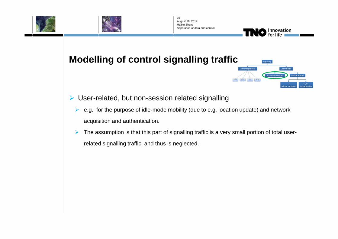
Modelling of control signalling traffic
� User-related, but non-session related signalling
� e.g. for the purpose of idle-mode mobility (due to e.g. location update) and network
acquisition and authentication.
� The assumption is that this part of signalling traffic is a very small portion of total user-
related signalling traffic, and thus is neglected.
August 18, 2014Haibin ZhangSeparation of data and control
19

Modelling of control signalling traffic
� Session-related L3 signals
� Mainly at session setup and (for mobile users) handover
� The total volume of signalling traffic is delivered by a sequence of signalling messages.
These messages have different sizes, consuming different amount of radio resources.
August 18, 2014Haibin ZhangSeparation of data and control
20
LTE session setup procedure for sessions without QoS requirements (default EPS bear)
(according to 3GPP TR 36.822)
Modelling of control signalling traffic
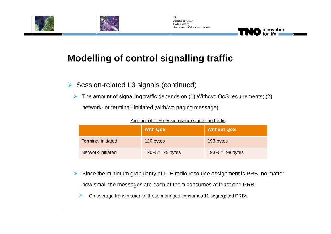
� Session-related L3 signals (continued)
� The amount of signalling traffic depends on (1) With/wo QoS requirements; (2)
network- or terminal- initiated (with/wo paging message)
� Since the minimum granularity of LTE radio resource assignment is PRB, no matter
how small the messages are each of them consumes at least one PRB.
� On average transmission of these manages consumes 11 segregated PRBs.
August 18, 2014Haibin ZhangSeparation of data and control
21
With QoS Without QoS
Terminal-initiated 120 bytes 193 bytes
Network-initiated 120+5=125 bytes 193+5=198 bytes
Amount of LTE session setup signalling traffic

Modelling of control signalling traffic
� Session-related L1/L2 signals
� Downlink L1/L2 control signals (mainly PDCCH), for scheduling, power control, etc.
� DM-RS, for demodulation of downlink user data. It is intended for a specific terminal
and is only transmitted in the resource blocks assigned for transmission to that
terminal.
August 18, 2014Haibin ZhangSeparation of data and control
22
[2]
[2]

Modelling of control signalling traffic
� PDCCH
� PDCCH is required both for the delivery of the session setup messages and the delivery
of data, noted as “PDCCH_s” and “PDCCH_d”, respectively.
� In LTE, PDCCH delivers Downlink Control Information (DCI) for active sessions. The size
of DCI differs according to the transmission mode used by the session (up to 70 bits)
� In LTE, the DCI is delivered using various number of Control Channel Elements (CCEs) in
the control region of each TTI, each consists of 36 resource elements of one OFDM
symbol. The number of CCEs used by a specific user depends on radio conditions, the
transmit mode of the user, etc. According to literature, in most cases 1 or 2 CCEs would
be sufficient.
� We assume 2 CCEs (72 REs) per active user in a specific TTI.
August 18, 2014Haibin ZhangSeparation of data and control
23
Modelling of control signalling traffic
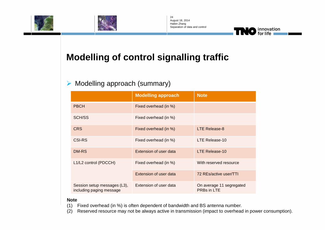
� Modelling approach (summary)
August 18, 2014Haibin ZhangSeparation of data and control
24
Modelling approach Note
PBCH Fixed overhead (in %)
SCH/SS Fixed overhead (in %)
CRS Fixed overhead (in %) LTE Release-8
CSI-RS Fixed overhead (in %) LTE Release-10
DM-RS Extension of user data LTE Release-10
L1/L2 control (PDCCH) Fixed overhead (in %) With reserved resource
Extension of user data 72 REs/active user/TTI
Session setup messages (L3), including paging message
Extension of user data On average 11 segregated PRBs in LTE
Note(1) Fixed overhead (in %) is often dependent of bandwidth and BS antenna number.(2) Reserved resource may not be always active in transmission (impact to overhead in power consumption).

Modelling of control signalling traffic
� In the case of user and data plane separation
� Signalling cell
� Fixed overhead: PBCH, SCH/SS, CSI-RS, PDCCH_s
� Extension of user data: session setup messages, DM-RS
� Data cell
� Fixed overhead: SCH/SS, CSI-RS (?)
� Extension of user data: DM-RS, PDCCH_d
August 18, 2014Haibin ZhangSeparation of data and control
25
Note: the capacity of PDCCH_s is limiting factor. So in order to have sufficient resource for PDCCH_s channels, we reserve e.g. M1=6 OFDM symbols within each TTI for PDCCH_s channels. It is beyond the current limit of LTE of M1<=4.
Note: the necessity of SCH/SS and CSI-RS depends on (1) the requirements of UE-data cell synchronisation, and (2) the synchronisation accuracy between the signalling and data cells.
Impact to the design of key network functions
August 18, 2014Haibin ZhangSeparation of data and control
26

Impact to the design of key network functions
August 18, 2014Haibin ZhangSeparation of data and control
27
Essential functions
� System information transmission
� Cell search (incl. synchronization)
� Paging
� Session setup procedure
� Mobility management
� Session management and
termination
� Dynamic on/off radio resources
Extended functions (not complete)
� Load balancing among cells
� Inter-cell interference coordination
� Advanced scheduling (exploiting e.g.
CoMP and carrier aggregation)
� Broadcast services (MBMS)
� Emergency services
� Self-X

Impact to the design of key network functions
August 18, 2014Haibin ZhangSeparation of data and control
28
Business-as-usual
� Cell search (of idle terminals)
� Paging
� Mobility management (idle terminals)
(only signalling-cells are involved)
Not business-as-usual
� System information transmission
� Session setup procedure
� Mobility management (active
terminals)
� Session management and
termination
� Dynamic on/off radio resources
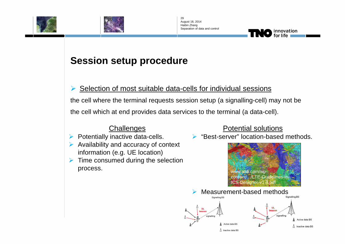
Session setup procedure
� Selection of most suitable data-cells for individual sessions
the cell where the terminal requests session setup (a signalling-cell) may not be
the cell which at end provides data services to the terminal (a data-cell).
August 18, 2014Haibin ZhangSeparation of data and control
29
Challenges� Potentially inactive data-cells.� Availability and accuracy of context
information (e.g. UE location)� Time consumed during the selection
process.
Potential solutions� “Best-server” location-based methods.
� Measurement-based methods
www.atdi.com/wp-content/.../LTE-Guidelines-in-ICS-Designer-v1.3.pdf

Session setup procedure
� (random) Access procedure (“idle-to-active” transit)
the terminal may need to perform two consecutive random access procedures:
“RACH_s” and “RACH_d”.
August 18, 2014Haibin ZhangSeparation of data and control
30
Challenges� Additional latency during “idle-to-
active” transits.
Potential solutions� Contention-free RACH_d facilitated by
RACH_s.� Data-cell selection and RACH-d in
parallel

Mobility management (active terminal handover)
� Handover of active terminals: scenarios
August 18, 2014Haibin ZhangSeparation of data and control
31
See next slide
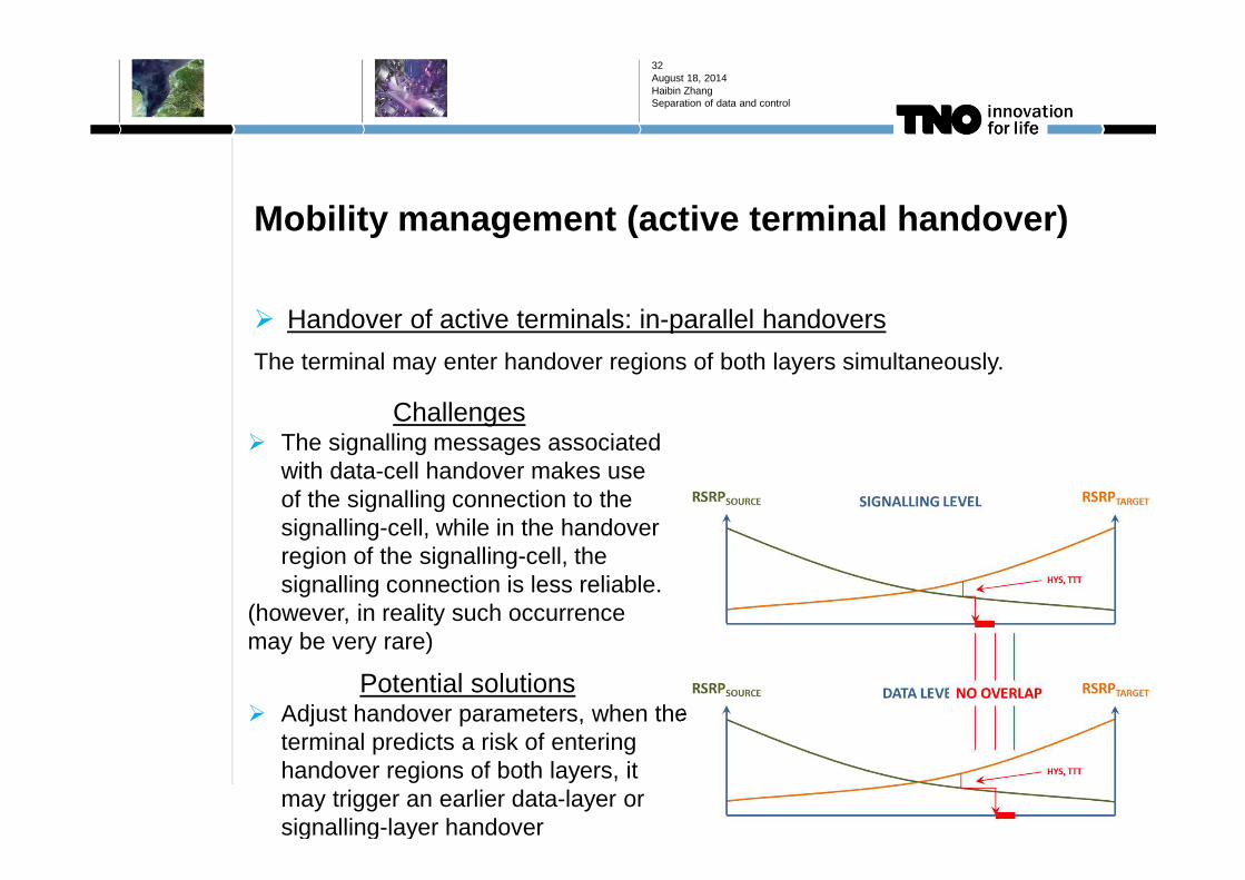
Mobility management (active terminal handover)
� Handover of active terminals: in-parallel handovers
The terminal may enter handover regions of both layers simultaneously.
August 18, 2014Haibin ZhangSeparation of data and control
32
Challenges� The signalling messages associated
with data-cell handover makes use of the signalling connection to the signalling-cell, while in the handover region of the signalling-cell, the signalling connection is less reliable.
(however, in reality such occurrence may be very rare)
Potential solutions� Adjust handover parameters, when the
terminal predicts a risk of entering handover regions of both layers, it may trigger an earlier data-layer or signalling-layer handover
Reference
1. R. Litjens, Y. Toh, H. Zhang, O. Blume, Assessment of the Energy Efficiency
Enhancement of Future Mobile Networks, IEEE WCNC 2014 Conference,
Istanbul, April 2014.
2. E. Dahlman, S. Parkvall, and J. Skold, LTE/LTE-Advanced for Mobile
Broadband, Chapter 10 & Chapter 14, 2011.
3. C. Hoymann, D. Larsson, H. Koorapaty, et al., A Lean Carrier for LTE, IEEE
Communication Magazine, vol. 51, no. 2, pp. 74-80, Feb. 2013.
4. H. Ishii, Y. Kishiyama and H. Takahashi, A Novel Architecture for LTE-B: C-
plane/U-plane Split and Phantom Cell Concept, IEEE Globecom Workshop:
International Workshop on Emerging Technologies for LTE-Advanced and
Beyond-4G, Anaheim, CA, USA, Dec. 2012.
August 18, 2014Haibin ZhangSeparation of data and control
33
Questions?
August 18, 2014Haibin ZhangSeparation of data and control
34