separation processes: adsorption - learnche.org · ilukchis, \adsorption systems: design by...
TRANSCRIPT

Separation Processes:
AdsorptionChE 4M3
© Kevin Dunn, 2013
http://learnche.mcmaster.ca/4M3
Overall revision number: 272 (November 2013)
1
Copyright, sharing, and attribution notice
This work is licensed under the Creative Commons Attribution-ShareAlike 3.0
Unported License. To view a copy of this license, please visit
http://creativecommons.org/licenses/by-sa/3.0/
This license allows you:
I to share - to copy, distribute and transmit the work
I to adapt - but you must distribute the new result under thesame or similar license to this one
I commercialize - you are allowed to use this work forcommercial purposes
I attribution - but you must attribute the work as follows:I “Portions of this work are the copyright of Kevin Dunn”, orI “This work is the copyright of Kevin Dunn”
(when used without modification)
2

We appreciate:
I if you let us know about any errors in the slides
I any suggestions to improve the notes
All of the above can be done by writing to
or anonymous messages can be sent to Kevin Dunn at
http://learnche.mcmaster.ca/feedback-questions
If reporting errors/updates, please quote the current revision number: 272
3

References used (in alphabetical order)I Geankoplis, “Transport Processes and Separation Process
Principles”, 4th edition, chapter 12I Ghosh, “Principles of Bioseparation Engineering”, chapter 8I Johnston, “Designing Fixed-Bed Adsorption Columns”,
Chemical Engineering, p 87-92, 1972I Lukchis, “Adsorption Systems: Design by Mass-Transfer-Zone
Concept”, Chemical Engineering, 1973.I Perry’s Chemical Engineers’ Handbook, 8th edition, chapter
22I Richardson and Harker, “Chemical Engineering, Volume 2”,
5th edition, chapter 17I Schweitzer, “Handbook of Separation Techniques for
Chemical Engineers”, chapter 3.1I Seader, Henley and Roper, “Separation Process Principles”,
3rd edition, chapter 15I Uhlmann’s Encyclopedia, “Adsorption”, DOI:10.1002/14356007.b03 09.pub2
I Wankat, “Separation Process Engineering”, chapter 164

This section in context of the course
I Continuous operationI SedimentationI Centrifuges, cyclonesI Membranes (except periodically backflushed to regenerate)I Liquid-liquid extraction
I Batch/cycled operationI filtration (e.g. plate and frame)I adsorption unitsI drying units (next)
Our goals
I understand what adsorbers look like and how they areoperated
I how to find the equilibrium isotherms for a new system
I preliminary sizing of an adsorption unit
5
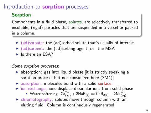
Introduction to sorption processes
Sorption
Components in a fluid phase, solutes, are selectively transferred toinsoluble, (rigid) particles that are suspended in a vessel or packedin a column.
I (ad)sorbate: the (ad)sorbed solute that’s usually of interestI (ad)sorbent: the (ad)sorbing agent, i.e. the MSAI Is there an ESA?
Some sorption processes:I absorption: gas into liquid phase [it is strictly speaking a
sorption process, but not considered here (3M4)]I adsorption: molecules bond with a solid surfaceI ion-exchange: ions displace dissimilar ions from solid phase
I Water softening: Ca2+(aq) + 2NaR(s) � CaR2(s) + 2Na+
(aq)
I chromatography: solutes move through column with aneluting fluid. Column is continuously regenerated.
6

Sorption examples
We will focus on (ad)sorption for the next few classes.
Some well-known examples:
I adsorption: charred wood products toimprove water taste
I adsorption: decolourize liquid with bone char
I adsorption: those little white packets inboxes of electronics
I ion-exchange: passing water through certainsand deposits removes salt
I ion-exchange: synthetic polymer resins widelyused to soften water
Industrial use of adsorption picked up with synthetic manufacturingof zeolites in the 1960s.
7
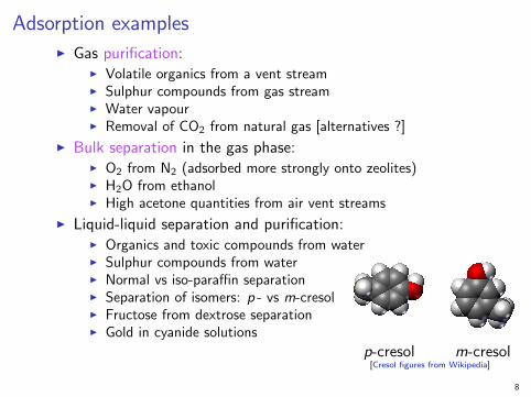
Adsorption examples
I Gas purification:I Volatile organics from a vent streamI Sulphur compounds from gas streamI Water vapourI Removal of CO2 from natural gas [alternatives ?]
I Bulk separation in the gas phase:I O2 from N2 (adsorbed more strongly onto zeolites)I H2O from ethanolI High acetone quantities from air vent streams
I Liquid-liquid separation and purification:I Organics and toxic compounds from waterI Sulphur compounds from waterI Normal vs iso-paraffin separationI Separation of isomers: p - vs m-cresolI Fructose from dextrose separationI Gold in cyanide solutions
p-cresol m-cresol[Cresol figures from Wikipedia]
8

AdsorbentsGeneral principle (more details coming up soon)
Molecules attach to theparticle’s surface: outside andon the pore walls
Main characterization: porediameter of adsorbent
Mechanisms duringadsorption
I equilibrium interaction:solid-fluid interactions
I kinetic: differences indiffusion rates
I steric: pore structurehinders/retains moleculesof a certain shape
[Modified from: Seader, 3ed, p 569] 9

Quick recap of some familiar concepts
I 1m = 100cm = 1000mm = 106µm= 109nm = 1010A
I Hydrogen and helium atoms: ≈ 1A
I For a pore:
Internal surface area
Pore volume=
πdpL
πd2pL/4
=4
dp
I dp = pore diameter: typically around 10 to 200 A
Our main concern is solid’s adsorption area per unit mass:
I solids are about 30 to 85% porous
I typical values: 300 to 1200 m2 per gram
I area of hockey field = 91.4 × 55 m = 5027 m2
10

Adsorbents
Helpful to see what they look like to understand the principles:
[Wikipedia, Active Al2O3.jpg]
Activated alumina
I made from fromaluminum hydroxide
I ∼ 300 m2 per gram
I most widely usedadsorbent
I hydrophilic
I pore diameter: 10 to75 A
11
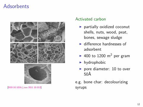
Adsorbents
[DOI:10.1016/j.saa.2011.10.012]
Activated carbon
I partially oxidized coconutshells, nuts, wood, peat,bones, sewage sludge
I difference hardnesses ofadsorbent
I 400 to 1200 m2 per gram
I hydrophobic
I pore diameter: 10 to over50A
e.g. bone char: decolourizingsyrups
12

Adsorbents
[Seader, 3ed, p575]
[Uhlmanns, p565]
Zeolite lattices
Some examples
K12[(AlO2)12(SiO2)12]:drying gases [2.9A]
Na12[(AlO2)12(SiO2)12]:CO2 removal [3.8A]
Ca43[(AlO2)86(SiO2)106]:air separation [8A]
Very specific porediameters.
I 40 naturally occurring
I ∼ 150 synthesized
I ∼ 650 m2 per gram 13
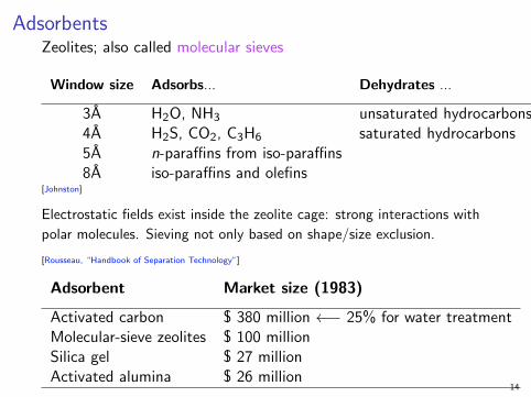
AdsorbentsZeolites; also called molecular sieves
Window size Adsorbs... Dehydrates ...
3A H2O, NH3 unsaturated hydrocarbons4A H2S, CO2, C3H6 saturated hydrocarbons5A n-paraffins from iso-paraffins8A iso-paraffins and olefins
[Johnston]
Electrostatic fields exist inside the zeolite cage: strong interactions with
polar molecules. Sieving not only based on shape/size exclusion.
[Rousseau, “Handbook of Separation Technology”]
Adsorbent Market size (1983)
Activated carbon $ 380 million ←− 25% for water treatmentMolecular-sieve zeolites $ 100 millionSilica gel $ 27 millionActivated alumina $ 26 million
14

Pore diameter characterization
[Seader, 3ed, p574] Determined using He and Hg porosimetry (see reference for details) 15

Example: Gold leaching and adsorption
I Crushed rock has gold particles exposed
I Leaching:4Au(s) + 8NaCN + O2 + 2H2O 4Na[Au(CN)2] + 4NaOH
I Adsorption: aurocyanide complex, Au(CN)−2 , is adsorbed ontoactivated carbon
I drives the equilibrium in the leaching step forwardI separates the solid gold, Au(s), from the pulp (slurry)I obtain CA,S ∼ 8000 grams of Au per tonne of carbon
I Desorption:I separate the highly concentrated
gold-carbon pulp (screens/filter/cyclones/sedimentation)
I desorb the gold off the carbonwith caustic contact
I recycle the regenerated carbon
16
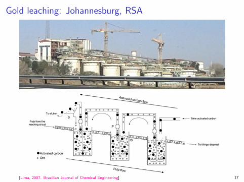
Gold leaching: Johannesburg, RSA
[Lima, 2007. Brazilian Journal of Chemical Engineering] 17
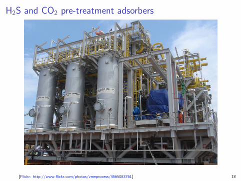
H2S and CO2 pre-treatment adsorbers
[Flickr: http://www.flickr.com/photos/vmeprocess/4565083761] 18

When to consider adsorptionDistillation, membranes, absorption, liquid-liquid extraction aresometimes viable alternatives.
But adsorption is considered when:I relative volatility between components is < 1.5 (e.g. isomers)I large reflux ratios would be requiredI too large area for a membraneI excessive temperatures or high pressure drops are to be
avoidedI high selectivity is requiredI feed is a very dilute stream of solute (adsorbate)
But, some disadvantages:I only the surface of the adsorbent usedI regeneration of MSA adsorbent requiredI MSA will break down mechanically over time as we move it
aroundI we must pump it, filter it, and/or put it through cyclones to
process it19
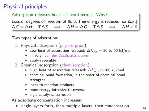
Physical principles
Adsorption releases heat, it’s exothermic. Why?
Loss of degrees of freedom of fluid: free energy is reduced, so ∆S ↓∆G = ∆H − T∆S =⇒ ∆H = ∆G + T∆S =⇒ ∆H < 0
Two types of adsorption:
1. Physical adsorption (physisorption):I Low heat of adsorption released: ∆Hads ∼ 30 to 60 kJ/molI Theory: van der Waals attractionsI easily reversible
2. Chemical adsorption (chemisorption):I High heat of adsorption released: ∆Hads > 100 kJ/molI chemical bond formation, in the order of chemical bond
strengthsI leads to reaction productsI more energy intensive to reverseI e.g.: catalysis, corrosion
As adsorbate concentration increases:I single layers form, then multiple layers, then condensation
20

Packed beds: adsorption and desorption steps
[Richardson and Harker, p 1028]
Regeneration reverses the adsorbate-adsorbent equilibrium:
1. raise the temperature to shift the equilibrium constant2. lower the pressure (vapour-phase adsorbate)3. displace the adsorbate with an alternative (e.g. steam)
Regenerate is shorter duration when done in the reverse directionto loading. 21
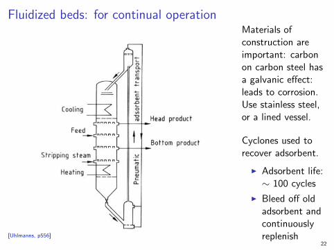
Fluidized beds: for continual operation
[Uhlmanns, p556]
Materials ofconstruction areimportant: carbonon carbon steel hasa galvanic effect:leads to corrosion.Use stainless steel,or a lined vessel.
Cyclones used torecover adsorbent.
I Adsorbent life:∼ 100 cycles
I Bleed off oldadsorbent andcontinuouslyreplenish
22

(Fluidized bed?) exampleAdsorption, Desorption and Recovery (ADR) plant in Burkina Faso
[Flickr #5043854546] Zoom in on the high resolution photo to see details.23

Modelling the adsorption process
1. DiffusionI diffusion of the adsorbate in the bulk fluid (usually very fast)I diffusion of the adsorbate to the adsorbent surface through the
boundary layerI diffusion of the adsorbate into the pore to an open site
I steric (shape) effects may be an issue
2. Equilibrium considerationsI adsorbate will attach to a vacant siteI adsorbate will detach from an occupied site
Mechanisms during adsorption
I equilibrium interaction: solid-fluid interactions
I kinetic: differences in diffusion rates (if multiple adsorbates)
I steric: pore structure hinders/retains molecules of a certainshape
24
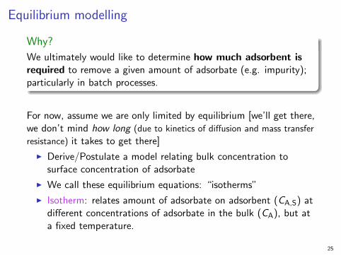
Equilibrium modelling
Why?
We ultimately would like to determine how much adsorbent isrequired to remove a given amount of adsorbate (e.g. impurity);particularly in batch processes.
For now, assume we are only limited by equilibrium [we’ll get there,we don’t mind how long (due to kinetics of diffusion and mass transfer
resistance) it takes to get there]
I Derive/Postulate a model relating bulk concentration tosurface concentration of adsorbate
I We call these equilibrium equations: “isotherms”
I Isotherm: relates amount of adsorbate on adsorbent (CA,S) atdifferent concentrations of adsorbate in the bulk (CA), but ata fixed temperature.
25
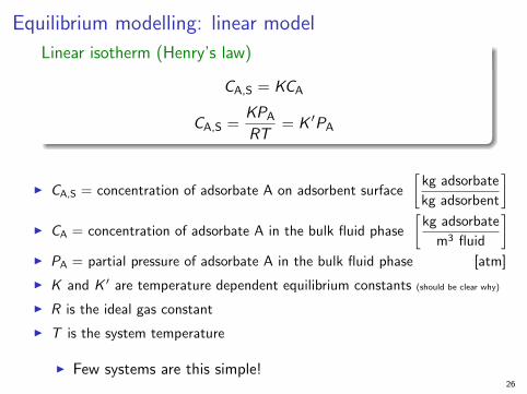
Equilibrium modelling: linear model
Linear isotherm (Henry’s law)
CA,S = KCA
CA,S =KPA
RT= K ′PA
I CA,S = concentration of adsorbate A on adsorbent surface
[kg adsorbate
kg adsorbent
]I CA = concentration of adsorbate A in the bulk fluid phase
[kg adsorbate
m3 fluid
]I PA = partial pressure of adsorbate A in the bulk fluid phase [atm]
I K and K ′ are temperature dependent equilibrium constants (should be clear why)
I R is the ideal gas constant
I T is the system temperature
I Few systems are this simple!26

Batch system example (previous midterm question)
You are to design a batch adsorber to remove an organiccontaminant (A) from 400L of aqueous solution containing0.05g/L of the contaminant. To facilitate this you do a benchscale experiment with 1L solution at the same concentration(0.05g/L) and 3g of an adsorbent. In the bench scale experimentyou find that 96% of the contaminant was removed. You need toremove 99% of the contaminant in the full scale apparatus. Youcan assume that a linear isotherm applies.
For the full scale system:
1. At the end of the batch, what will be the concentration of thesolution in the adsorber and concentration of A on theadsorbent?
2. How much adsorbent do you need? [Ans: 4.95 kg]
27

Equilibrium modelling: Freundlich model
Freundlich isotherm
CA,S = K (CA)1/m for 1 < m < 5
I It is an empirical model, but it works well
I Constants determined from a log-log plotI How would you go about setting up a lab experiment to
collect data to calculate K?I Which way will the isotherm shift if temperature is increased? 28
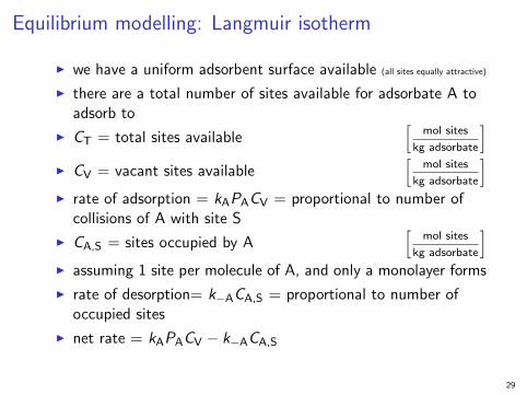
Equilibrium modelling: Langmuir isotherm
I we have a uniform adsorbent surface available (all sites equally attractive)
I there are a total number of sites available for adsorbate A toadsorb to
I CT = total sites available[
mol sites
kg adsorbate
]I CV = vacant sites available
[mol sites
kg adsorbate
]I rate of adsorption = kAPACV = proportional to number of
collisions of A with site S
I CA,S = sites occupied by A[
mol sites
kg adsorbate
]I assuming 1 site per molecule of A, and only a monolayer forms
I rate of desorption= k−ACA,S = proportional to number ofoccupied sites
I net rate = kAPACV − k−ACA,S
29

Equilibrium modelling: Langmuir isothermI Net rate = kAPACV − k−ACA,S
I define KA =kA
k−A
I essentially an equilibrium constant: A + S A · SI at equilibrium, the net rate is zero
I implyingkACA,S
KA= kAPACV
I but total sites = CT = CV + CA,S
I sokACA,S
KA= kAPA (CT − CA,S)
I simplifying: CA,S = KAPA (CT − CA,S)
I then CA,S =KACTPA
1 + KAPA=
K1PA
1 + K2PA=
K3CA
1 + K4CA
I Fit data using Eadie-Hofstee diagram or nonlinear regression
I Same structure as Michaelis-Menten model (bio people)
30
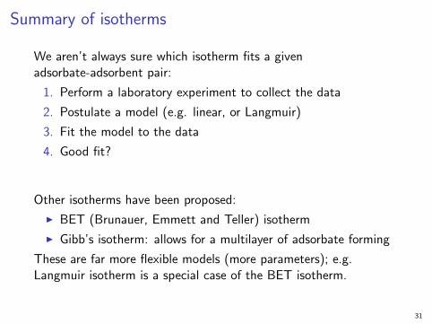
Summary of isotherms
We aren’t always sure which isotherm fits a givenadsorbate-adsorbent pair:
1. Perform a laboratory experiment to collect the data
2. Postulate a model (e.g. linear, or Langmuir)
3. Fit the model to the data
4. Good fit?
Other isotherms have been proposed:
I BET (Brunauer, Emmett and Teller) isotherm
I Gibb’s isotherm: allows for a multilayer of adsorbate forming
These are far more flexible models (more parameters); e.g.Langmuir isotherm is a special case of the BET isotherm.
31
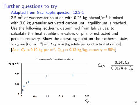
Further questions to tryAdapted from Geankoplis question 12.2-12.5 m3 of wastewater solution with 0.25 kg phenol/m3 is mixedwith 3.0 kg granular activated carbon until equilibrium is reached.Use the following isotherm, determined from lab values, tocalculate the final equilibrium values of phenol extracted andpercent recovery. Show the operating point on the isotherm. Units
of CA are [kg per m3] and CA,S is in [kg solute per kg of activated carbon].
[Ans: CA ≈ 0.10 kg per m3, CA,S ≈ 0.12 kg/kg, recovery = 58%]
Experimental isotherm data
CA,S =0.145CA
0.0174 + CA
32

Isotherms change at different temperatures
[Seader, 3ed, p610] 33
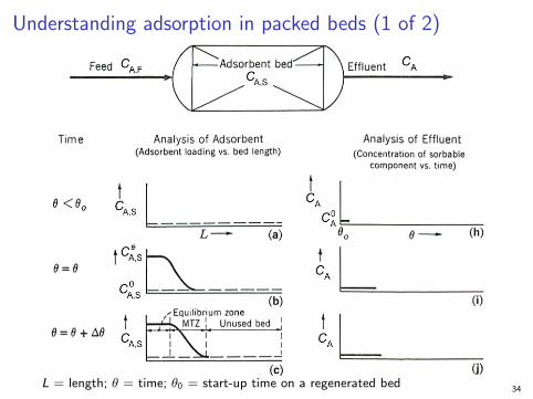
Understanding adsorption in packed beds (1 of 2)
L = length; θ = time; θ0 = start-up time on a regenerated bed34

Understanding adsorption in packed beds (2 of 2)
[Lukchis]
I CA,S = concentration of adsorbate on adsorbent
I C eA,S = concentration at equilibrium on the adsorbent (equil loading)
I C 0A,S = concentration on the regenerated adsorbent at time 0
I θb = breakthrough time: “time to stop using the packed bed! ”; usuallywhen CA = 0.05CA,F
I θe = the bed at equilibrium time; packed bed is completely usedI CA,S values are not easy measured; outlet concentration CA is easy 35
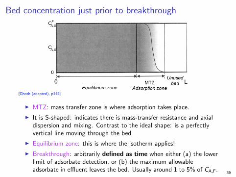
Bed concentration just prior to breakthrough
[Ghosh (adapted), p144]
I MTZ: mass transfer zone is where adsorption takes place.
I It is S-shaped: indicates there is mass-transfer resistance and axialdispersion and mixing. Contrast to the ideal shape: is a perfectlyvertical line moving through the bed
I Equilibrium zone: this is where the isotherm applies!
I Breakthrough: arbitrarily defined as time when either (a) the lowerlimit of adsorbate detection, or (b) the maximum allowableadsorbate in effluent leaves the bed. Usually around 1 to 5% of CA,F.
36

Figures to help with the next example
[Seader, Henley, Roper, p 605] 37

Terminology
I LES = length of equilibrium section (increases as bed is used)
I LUB = length of unused bed (decreases as bed is used up)
I L = total bed length = LES + LUB
I No data available: use MTZ distance of 4ft
38

Example (and some new theory applied)
An adsorbate in vapour is adsorbed in an experimental packed bed.The inlet contains CA,F = 600 ppm of adsorbate. Data measuringthe outlet concentration over time from the bed are plotted below:
[Geankoplis, 4ed, p 768]
39

Example
1. Determine the breakthrough time, θb. [Ans: 3.65 hours]
2. What would be the usable capacity of the bed at time θb if wehad an ideal wavefront (no mass transfer resistance)? [Ans: thefractional area of A1 = 3.65 / 6.9 = 53%]
I Note plot area units = “total time”, since “height” of y-axis = 1.0I Note: (area up to θb) ≈ θb when using a normalized y-axis
3. How long does it take to reach this ideal capacity? ≈3.65 hoursIgnore the tiny part missing from the integrated area.
40

Example
4. What actual fraction of the bed’s capacity is used at θb?
I The actual capacity used is the total shaded area = A1 + A2
I This is called the stoichiometric capacity of the bedI Ideally, if there were no mass transfer resistance (i.e. spread in the
breakthrough curve), then theI stoichiometric time, θS , is defined as time taken for this actual
capacity to be usedI θS is the point that breaks the MTZ into equal areas: in this case, A2
vs the unshaded area in previous diagram
I θS =
∫ ∞
0
(1−
CA
CA,F
)dt = shaded area = A1 + A2 = 3.65 + 1.55 = 5.20 hrs
I So actual bed fraction used at θb is5.2
6.9= 0.75 ∼ 75%
41

Figures to help with the example
5. If the lab-scale bed was originally 14cm long, what equivalent“length” is unused at time θb?
I intuitively: (1− 0.75)× 14 cm = 3.5 cmI LUB = length of unused bed = 3.5 cmI LES = length of equilibrium section = the used up part =
14.0− 3.5 = 10.5 cm 42

Example
6. If we wanted a break-point time of θb = 7.5 hours instead, how muchlonger should the bed be (keeping the diameter and flow profile fixed)?
Current DesiredLES 0.75× 14 cm = 10.5cm 21.6cmLUB 0.25× 14 cm = 3.5cm 3.5cm
Total 14cm 25.1cm
I Ratio LES lengths to breakthrough times:LESdes
LEScurr =θdesb
θcurrb
I Length to get to breakthrough in 7.5 hours = LESdes = 21.6 cmI We have to add on the length of the unused bed = 3.5 cm from
before (same diameter, same flow profile!)I So new bed length = LES + LUB = 21.6 + 3.5 = 25.1 cmI LUB is the same length, provided all other conditions are the same
I Then fraction actually used =21.6
24.5= 0.88 (compared to 0.75)
43

Bed mass balance
Amount of material loaded into the bed up to θb in LES
QF CA,F θb = C eA,S ρB ALLES
QF Feed flow rate
[m3
second
]CA,F Inlet concentration
[kg solute
m3 fluid
]θb Breakthrough time [second]
C eA,S Eqbm adsorbed solute concn
[kg solute
kg adsorbent
]ρB Adsorbent’s bulk density
[kg adsorbent charged
m3 of occupied space
]ALLES Bed volume = area × LES length
[m3 of occupied space
]Add on LUB; determine volume adsorbent required = A(LLES + LLUB).
Take porosity into account when calculating mass of adsorbent from the
occupied volume.44

Modified from a previous examTrimethylethylene (TME) is being removed from an aqueouschemical plant waste stream on a continuous basis (this is not abatch system). A bench scale system indicates that the adsorbentfollows a Langmuir adsorption isotherm as:
CA,S =0.05CA
32.1 + CA
where CA,S has units of [grams/grams], and the constant has unitsof 32.1 ppm. In a tank we have an inlet flow of TME solution at10L/min with density of 1000 kg.m−3. The TME enters at 100ppm (parts per million, mass solute per 106 mass solution) in thefeed. The impurity is not detectable below 1 ppm concentrations.The tank contains 15 kg of initially fresh adsorbent which isretained in the tank. We wish to know:
1. How much TME is adsorbed when the breakthroughconcentration reaches 1 ppm? [Ans: 22.66 g]
2. How long it will take to reach this detectable outletconcentration? [22.6 minutes]
45

Regenerating the bed
Aim
To remove adsorbate from the packed bed.
1: Temperature swing adsorption (TSA)I heat the bed: usually steam is used (due to high latent heat)
I why add heat? (recall, heat is released during adsorption)
I creates a thermal wave through the packed bed
I isotherm at higher temperature is shifted down
I causes the adsorbate to be diluted in the stripping fluid
I often leave some residual adsorbate behind, since time tocompletely strip adsorbent of it would be excessive
I care must be taken with flammable adsorbates:I stripping temperatures are highI often near flammable limitsI carbon beds have been known to catch fire
See illustration on next page to understand TSA46

Regenerating the bed2. Pressure swing adsorption (PSA)I used when the “product” is the cleaned (stripped) fluidI add feed with adsorbate at high pressure (loads the adsorbate)I drop the pressure and the adsorbate starts to desorbI run two beds in parallel (one desorbing, the other adsorbing)I widely used for portable oxygen generation, H2S capture in
refineries
[Seader, 3ed, p610] 47
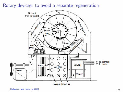
Rotary devices: to avoid a separate regeneration
[Richardson and Harker, p 1034] 48

Adsorption equipment: Sorbex columnBed remains stationary (minimizes adsorbent damage); fluid phase is pumped around.
Simulates a counter-current movement of solid to liquid.
[Seader, Henley, Roper, p 611]
A) Pump; B) Adsorbent chamber; C) Rotary valve; D) Extract column; E) Raffinate column
49