sept. 16, 1952 frederick. k. maussnest 2,610,524 now … · mechanical presses whose slide or...
TRANSCRIPT
Sept. 16, 1952 FREDERICK. K. MAUSSNEST 2,610,524 NOW BY CHANGE OF NAME
FREDERICK K. MAUST COUNTERBALANCING DEVICE
Filled June 23, 1948 5 Sheets-Sheet l
as N T ZS NN 12.SS-en TÉ N-3 53 SAN ANSENA SSSN A Z: 3. 2 % 24
5. v 624.4/25 T-2 AvoW as Y craws as OAAAirwa
Aaeoleaica A. MAus7,
Sept. 16, 1952 FREDERICK K. MAUSSNEST 2,610,524 NOW BY CHANGE OF NAME
FREDERICK K. MAUST COUNTERBALANCING DEVICE
Filed June 23, 1948 5 Sheets-Sheet 2
- -27 - 64
El----- ---ish, 66 w f, f : - 26 7, Zaz Z : - N 72/ 2, 1. N 72
N 77 N N 73 N
r N N Lll- N S s 2
|60 76 49 \ gift 40
6a || 7 || E -
24 67. --
a is e !---- -
E.g.
: frt EE :
A.
. ts INVENTOR.
A. 2 Azéle?M14&e Nod isy e-AAVGe. f NAME FaeDepicz K. M. Aust
Sept. 16, 1952 FREDERCK K. MAUSSNEST 2,610,524 NOW BY CHANGE OF NAME
FREDERICK K. MAUST COUNTERBALANCING DEVICE
Filed June 23, 1948 5 Sheets-Sheet 3
i s E s
S. NYaYaN, SNNA s SA
Stsia EggenS ENSE N s
7 2ZZ2 2s2Sz 2. s 224227XYZ 2 W2 as 31
o 22 %
nou by e-Ameat of mamg P2eo Alcia. K. MAST
Sept. 16, 1952 FREDERICK K. MAUSSNEST 2,610,524 NOW BY CHANGE OF NAME
FREDERICK K. MAUST COUNTERBALANCING DEVICE
Filed June 23, 1948 5 Sheets-Sheet 4.
N
2.ÉN SN NN EN EN
ANNYNNYNNNNY&
22 N 2 3 22.SS 23S 2:n, 22% N 22 &S
SSN: NaN As NN NaN. N 3%
SN 2ab, IN N NZ 2. N N Set % N 3. Šgn life
NHS ZS NSN Neer ar Safs, N N SSS N 22
A.
N2 A
AY1
al
f M Z
2722, 16 , 151 37
25 127 2.3%.
INVENTOR.
measy Chaavae of NAMe Fiza deatcruz k. MAust
Sept. 16, 1952 FREDERCK K. MAUSSNEST 2,610,524 NOW BY CHANGE OF NAME
FREDERICK K. MAUST COUNTERBALANCING DEVICE
Filled June 23, 1948 5 Sheets-Sheet 5
y
y :
SS S27. '72/S S N SY
-
- 274 a1% 2
INVENTOR.
A2a24%, 64.7 Nou 3y CHAnga or mame fa?t of pic14 A. A1A57
Patented Sept. 16, 1952 2,610,524
UNITED STATES PATENT OFFICE 2,610,524
COUNTERBALANCNG EDEVICE Frederick K. Maussnest, Queens Village, N. Y., now by change of name Frederick K. Maust Application June 23, 1948, Serial No. 34,645
(C. 4-693) 4 Caixas. 1.
This invention relates in general to balancing. devices for completely counterbalancing. Crank actuated reciprocating mechanisms, i. e., mecha nisms for changing a substantially uniform ro tary motion into a reciprocating motion, or Vice versa, and more particularly to balancing means for punch presses of all kinds which employ driveshafts with crankarms or crankpins, or driveshafts carrying eccentrics or eccentrics mounted on bull gears, herein simply called crankshafts, in combination with connecting rods or sliding blocks for reciprocating their Working heads or Slides. - - The term “punch press' is used hereinafter
in its broadest sense and includes any and all mechanical presses whose Slide or slides are re ciprocated by crankshafts with single cranks or multiple cranks or eccentrics, defined in this art as single crank presses, double crank preSSeS, multiple slide presses, four point Suspension preSSes, etc. Mechanical punch presses are nearly exclu
sively built on the above described crank prin ciple because of the many advantages of con struction and simplicity of design. Crank mo tions of this type are, however, unfortunately inherently unbalanced. High speed operation of punch presses, and
especially of punch presses with automatic feeds capable of utilizing practically every working stroke of the machine, has been the aim of the metal working and stamping arts for many years. Solutions have been offered heretofore which consisted in either different actuating notions for the slides, or in arranging dummy slides which reciprocate in opposite direction to the working slides without doing any useful work. The cost of construction of such equipment con pared with conventional presses of similar ton nage capacity appears out. of proportion con pared with the results obtained. The unbalanced forces encountered in the op
eration of a reciprocating crank mechanism or kinematically equivalent System, such as a punch press, may be conveniently divided into three distinct classes.
O
5
20
25
30
35
2 caused by the reciprocating slide With its aSSO ciated elements. These forces will be called in short 'primary' and 'secondary' inertia forces. While the reciprocating inertia forces of such crank actuated reciprocating Systems which en ploy pitmans have theoretically an infinite nun ber of harmonics of even number, only the first and second harmonics will be considered here, because they represent Very nearly the true slide motion. The frequency of the harmonic fixes the rate of rotation, the first harmonic having crankshaft speed, the second harmonic having twice crankshaft speed. The secondary inertia, forces already are of comparatively small magni tude, i. e. equal to the primary inertia, forces divided by the ratio of connecting rod length over the crank radius. This ratio is usually on the order of about 10:1 to 15:1 in punch presses. These figures are not given in any limiting sense, but only to make visualization of the relative. forces easier. The slide motion of presses which employ
a sliding block surrounding an eccentric is a simple harmonic, because the connecting rod of finite length is eliminated. The total inertia, forces of the reciprocating mass are therefore simply the primary inertia forces.
3rd: In addition to the dynamic inertia, forces which appear as a result of the motion of the machine, the static weight of the reciprocating slide assembly exerts a steady and constant downward force in a vertically placed crank nechanisin of this character. To obtain complete balance, all inertia forces
and the static weight of the slide assembly must be counterbalanced by equal and opposite forces. Otherwise the unbalanced forces will act on the crankshaft and consequently on the main bear ings of the machine, thereby increasing the
40
1st: The unbalanced rotational inertia forces caused by the rotating crankarm or crankpin including those associated, elements which may be considered as partaking of its rotary motion. These rotational inertia, forces may be neutral ized by masses attached to the crankshaft dia metrically opposite the crankpin at a radius that depends on the magnitude of the mass attached. 2nd: The primary and secondary inertia forces
50
cushions.
bearing load and setting up forced vibrations. The latter not only limit the speed of operation, but must be absorbed by the main frame or foundation. - .
The balancing of the rotational inertia forces by attaching counterweights to the crankshaft has found little application in punch presses be Cause of Space limitations and particularly for the reason that this method alone accomplishes at-best only a partial solution to the existing Vibration problems. Therefore, the usual extent of counterbalancing the unbalanced static and dynamic forces in presses has been heretofore restricted to single or compound springs or air
t is obvious that simple harmonics in different frequencies cannot be counterbai
2,610,524. 3.
anced effectively in this manner because the force created by compressing a Spring, for in stance, is a linear function of the distance of compreSSion. The present invention not only modifies the
inertia forces of the reciprocating masses but provides for their complete counterbalancing by means of compact and comparatively inexpensive balancing. neains. may be employed in conjunction. With conven tional punch presses with little or no change in their present design. I accomplish the balancing effect by the provision of a plurality of novelly arranged and actuated rotating counterweights which act in opposition to the rotational-and reciprocating inertia forces, respectively, and by air cushions or springs for neutralizing the static weights, as will be fully shown and described: hereinafter. More specifically, one object of my invention is
to provide balancing means for reciprocating crank systems of the character described for neutralizing the rotational and the primary 'in ertia forces by employing two or more counter weights which revolve synchronously with the drive shaft or crankshaft, at least one of said counterweights being adapted to revolve in the same direction and at the same speed as the crankshaft, and at least one other counterweight being adapted to revolve at the same speed but in opposite direction to the crankshaft. Another object is to provide the just mentioned
balancing means with additional counterweight ing means adapted to rotate at twice crankshaft. speed for also. neutralizing, the secondary inertia, forces. A further object is to provide compact, self
contained. balancing units which may be conven iently attached singly or in multiples to punch presses or other equipment to be balanced and in which bevel gearing is employed for imparting. the proposed directions and Speeds to the coun terweighting. means. Another object is to provide novelly, arranged.
air cushions and/or springs...in conjunction with. punch presses for off-setting the static weight of the slide assembly, These and other objects and advantages: will
become better understood as the following de Scription of certain present preferred embodi ments proceeds. In the accompanying drawings. I have shown by way of example said present, pre ferred embodiments, in which
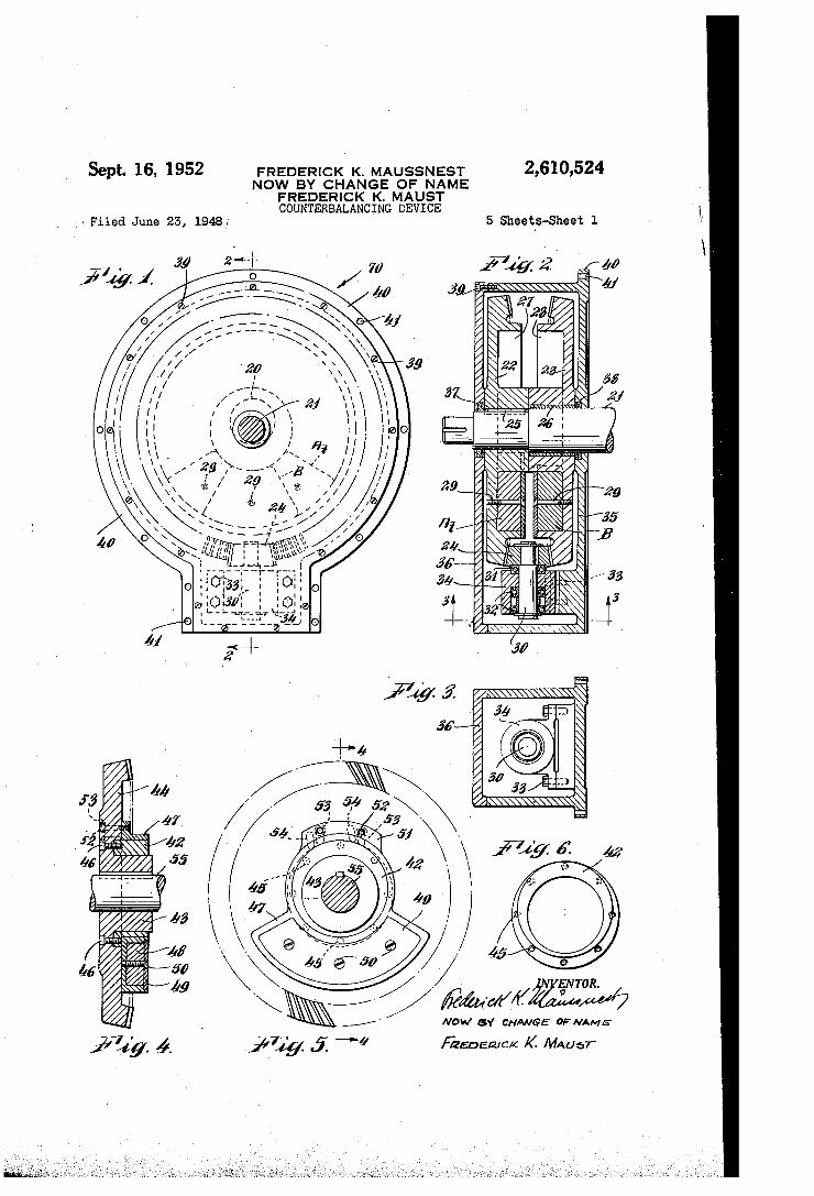
Fig. 1 is a right hand side-view along line - of the balancing unit shown- in Fig. 7 (press frame and mounting bolts: not shown) for off setting- rotational as well as-primary inertia forces,
Fig. 2 is a Section-along line 2-2 in Fig. i. Fig. 3 shows a partial end view taken along
The novel-balancing nea, S.
5
O
20
30
35
40
45
50
55
60
line-3-3. of Fig.2 and is intended to depict spe cifically-the-bearing bracket for the pinionishaft.
Fig. 4. Shows a modification of the bevel. gears exemplifying ani-eccentric mounting of the coun terweighting masses in section along line. 44 of Fig.5:
Fig. 5 is a right hand side view of the bevel gear shown in Fig. 4.
Fig.6 shows in detail the eccentric bushing fo Carrying the counterweight.
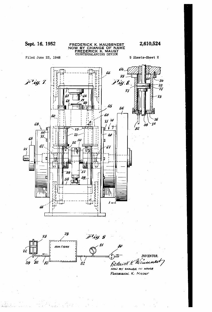
Fig. 7 depicts the application of balancing units shown in Figs. 1 to 3 to an underdrive. punch preSS in combination. With air cylinders located concentrically with the guide rods.
65
70
4 Fig. 8 is a cross-section of an air cylinder along
line 8-8 of Fig. 7. Fig. 9 shows diagrammatically the connection
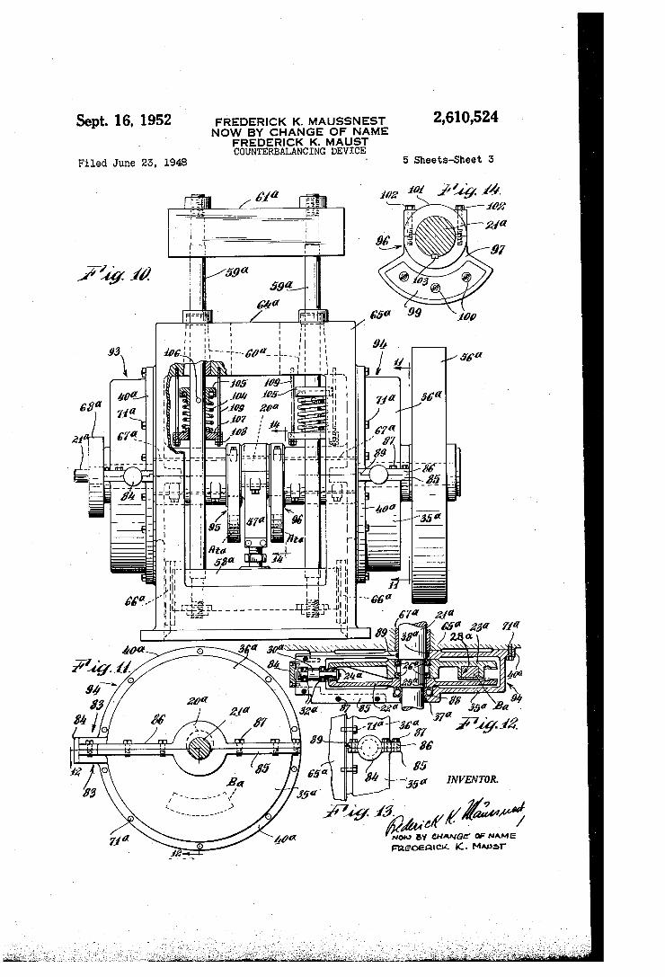
of the air cushion to an air tank. Fig. 10 shows an underdrive punch preSS With
twin balancing units and Separate CounterWeightS on the cheeks of the crankshaft together With Springs arranged concentrically with the guide rods for off-setting the static. Weight.
Fig. 11 illustrates a right hand side view of the balancing unit employed in Fig. 10 as seen along line - of Fig. 10, press frame and mounting bolts not shown.
Fig. 12 is a cross-sectional view along line 2-2 of Fig.11. Fig.13 shows-a-partial left hand side view of the
balancing unit illustrated in Figs. 11 and 12. Fig. 14 depicts one of the counterweights on
the-cheeks of the crankshaft along line 4-4 of Fig. 10.
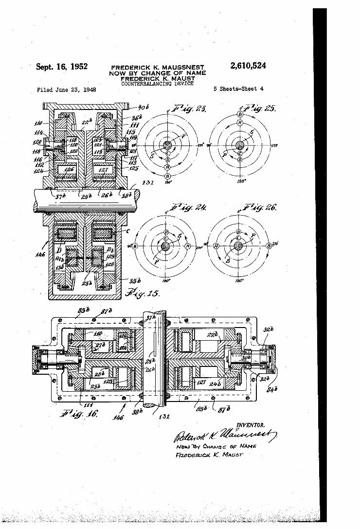
Fig. 15 is a vertical cross-section through the balancing unit, along line 5-5 of Fig. 18, press frame and mounting bolts not shown.
Fig. 16 is a horizontal cross-section through the same unit along line 6-6 of Fig. 18.
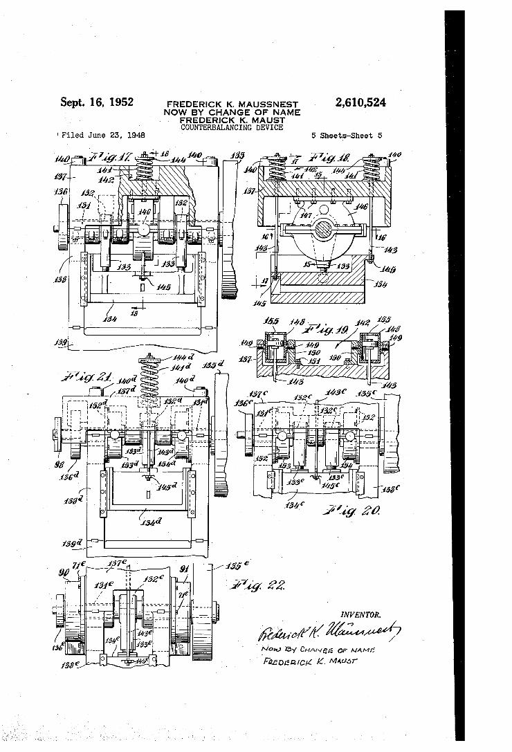
Fig. 17 shows a double crank press with cen trally located balancing unit, partly in section along line? 7-7 of Fig. 18.
Eig. 18 is a fragmentary Section alone line f8-8 of Fig. 17 depicting the crown and slide of the press.
Fig. 19 shows, a fragmentary section of the crown of the press shown in Fig. 18, exemplifying the USe of air cushions instead of Springs.
Fig. 20 illustrates the application of twin bal ancing units inside... the press frame of a double crank press of which only a fragmentary front elevation is shown.
Fig. 21 shows a partial front view of a single crank press with twin balancing units mounted inside the press frame.
Fig. 22 also depicts a partial front view of a single "Crank press with twin balancing units. on the outside of the press frame.
Figs. 23, 24, 25, and 26 show diagrammatically the relative positions of the rotating counter Weights for neutralizing the primary and the sec ondary inertia, forces with the crankshaft in the 0°, 90°, 180°, and 270 positions, respectively.
Referring now more particularly to the draw ings, the relative positions of the counterweights for neutralizing. the primary and secondary in ertia forces are shown diagrammatically in Figs. 23 to 26. In Fig. 23 the crankpin or crankarm P is at tOp dead center which is designated as the 0 position. The crankshaft S is assumed to be rotating in counterclockwise direction. The counterweight or mass A rotates in the same di rection and at the same speed as the crankshaft S and is located diametrically opposite the crank pin P, i. e. at bottom dead center at this instant. Counterweight Brotates in opposite direction to Crankshaft. S but at the same speed and is co incident in this crank position with weight A at bottom dead center. These two counterweight ing masses A and B, rotating at crankshaftspeed but in respective opposite, directions, will com pietely neutralize, oppose or counterbalance the primary inertia forces, provided their radii of . rotation and their respective masses are so chosen that each one of the counterweights A and B off-sets substantially one-half of the primary in ertia forces to be counterbalanced.
It should be noted in this connection that mass A is located opposite the crankpin P so that a
2,610,524. 5
counterweight for neutralizing the rotational in ertia forces may be conveniently combined there With, if desirable. The counterweight Crotates in the same direct
tion as the crankshaft S but at twice its speed. CounterWeight D rotates in opposite direction to the crankshaft and also at twice its speed. Coun terWeighting masses A, B, C, and D act vertically doWinWards With no horizontal force components and are coincident at bottom dead center in the 0 position of crankpin. P. The radii of rotation and the maSSes of counterweights C and D are preferably so chosen that each mass neutralizes Substantially one-half of the secondary inertia, forces to be counterbalanced. . . .
Fig. 24 depicts the crankshaft S after having made one quarter of one revolution, having thus arrived at the 90° position. Counterweights A and B also have advanced 98° in their re Spective directions of rotation and have arrived at the 270 and 90° positions, respectively. Their centrifugal forces have no vertical components and act horizontally in opposite directions, thus cancelling each other. Masses C and D are in the 0 position and act vertically upwards with out horizontal components.
Fig. 25 shows the crankshaft at botton dead Center (180°) position. Counterweights. A and B are at top dead center and their centrifugal forces act vertically upwards with no horizontal Components. Masses C and D are at botton dead center; their forces act vertically down Wards With no horizontal components.
Fig. 26 illustrates the positions of the several counter Weights with the crankshaft in the 270° position. The maSSes A and B act in horizontal, but opposite directions and therefore cancel each other. They have no vertical force components. Counterweights C and D have arrived at top dead center and exert vertical upward forces without horizontal components. After another quarter revolution, the crank
O
5
20.
2 5
3)
40
shaft and counterweights assume again their original positions shown in Fig. 23 and the cycle repeats itself. During one complete revolution of the crankpin
P, all balancing weights are coincident at bot tom dead center when the crankpin P is at top dead center; masses A and B are coincident at top dead center with the crankpin at bottom dead center; counterweights C and D are coin cident at top dead center with the crankpin in the 90° and 270° positions; masses C and D are also coincident at bottom dead center when crankpin P is at botton dead center. While the positions of the several counter
WeightS have been shown for full quarter revolu-. tions of the crankshaft only, it will be obvious from the diagrams that the symmetrically ar ranged counterrotating pairs of masses A, B and C, D will introduce no unbalanced horizontal centrifugal force components in any crank posi tions, but will produce, when the masses and their radii of rotation are chosen as previously indicated, counterbalancing or off-setting cen trifugal forces of their own of such magni
55
60
35
tudes and directions as to oppose and thus elim inate the harmful primary and secondary inertia forces of reciprocating crank Systems. Means will be described hereinafter to actuate the sev eral counterweights at the speeds and in the di rections diagrammatically indicated in Figs. 23 to 26 in positive synchronism with the crankshaft. rotation. Consequently, a perface balance may be accomplished at any operating speed, because
70
75
6 it is axiomatic that if the mechanism is brought into balance at one speed, it will also be in balance at any other speed.
Figs. 1 to 3 show a balancing apparatus for opposing the rotational inertia, forces and the primary inertia forces. The unit may be mounted directly on a crankshaft 2 which may be in top dead center position as indicated in Fig. 1 by the numeral 2. On the driveshaft 2, two bevel gears 22 and 23 are mounted in face-to face and Spaced relation and are in nesh. With a right angle bevel pinion 24. Bevel gear 22 may be secured to shaft 2 by a key 25, while gear 23 is freely rotatable on bushing 26. When shaft 2 is rotated, bevel gear 22 will rotate in the same direction as crankshaft 2 and gear 23 Will be forced to revolve at the same speed but in opposite direction, thereto. Bevel gears 22 and 23 are equipped with annular pockets 2 and 28 for carrying counterweights. At and B, respec tively. These counterweights may be fastened to the bevel gears in any desirable position by means of bolts 29 or the like in the annular pock ets 27 and 28. With the crankpin 29 at top dead center, they are preferably located coinci dent at bottom dead center position as ShoWn. Both counterweights may possess the Same radius of rotation, but maSS At is shown considerably larger than maSS B. According to previous ex planations, the two counterrotating Weights A and B in Figs. 23 to 26 should preferably be adapted to cause centrifugal forces of substan tially the same magnitude, and hence, with identical radii of rotation, their masses should be equal. However, as also pointed out previously, the rotational inertia forces may be neutralized by a Suitable counterweight or counterweights attached to the crankshaft diametrically oppo site the crankpin. The additional mass re quired for off-setting the rotational inertia, forces is therefore shown combined with the Weight A of Figs. 23 to 26, resulting in the mass At whose weight is such as to neutralize Substantially One half of the primary inertia, forces plus the rota tional inertia forces. When equal centrifugal forces of necessary
magnitudes are developed by masses. At and B, this balancing unit will counteract the primary inertia forces only, as pointed out above. Equal centrifugal forces will be produced when em ploying balancing masses of the same specific gravity, equal size, and identical radii of rota tion; or by maintaining the relative sizes and equal radii of rotation of At and B as shown in Fig. 1, but selecting for At a material of lesser specific gravity than for B; or by reducing the radius of rotation of mass At as compared with that of B by such means as will be described in connection with Figs. 4, 5, 6; or by a combina tion of Some or all of these expedientS.
Pinion 24 may be keyed to shaft 3 which is rotatably mounted in thrust bearing 3 and ball bearings 32 of bearing bracket 34 fast to bell shaped casing 35 by means of bolts 33. Casing 33 may be conveniently provided with a front cover 36 secured thereto by bolts 39. To prevent leak age, seals 37 and 38 may be placed around the driveshaft 24. Housing 35 may have a flange with bolt holes 4 for securing the balancing unit to a stationary part of the machine to be balanced.
Figs, 4 to 6 show a modification in the mount ing of the counterweights which may be employed for any balancing unit. An eccentric sleeve 42 is adjustably mounted on the hub 43 of the bevel gear 44 and provided. With a Series of tapped bolt
2,610,524. 7.
holes: 45 whose centers are on a circle: concentric with hub. 43 for fastening the eccentric: A2; in any desired angular position to the Web of bevel gear 44 by means of botS 6 extending through match ing holes in the Web. of the bevel gear. Casing. filis disposed on eccentric sleeve. 42 and provided Witha, Suitable pocket for receiving the counter-. Weighting maSS: 48, which may consist of any heavy. Substance, Such as lead, held in place by cover 49, and boltS. 50. Casing 47 is equipped with a flange: 5 having threaded holes, adapted to receive bolts 52 extending through, slotS 53 in the Web of bevel gear 44. Any number of addie. tional Suitably located slots.a.S. indicated by 54. may be arranged for the: angular displacement of the counterWeight. m
Figs. 4 and 5 show the counterweight 48 in the position nearest the axis of rotation. of shaft, 55. By turning the eccentric: sleeve. 42, the, radius of rotation of the: counterweight may be increased, whereby the centrifugal counterbalancing force. produced by the counterWeight is increased act. cordingly. To compensate for this radial dis placement, openings 53 and 54. are of slot shape. The eccentric and angularly adjustable mount
ing of the counterweight. 48 above: described may be of special advantage when the balancing units are: employed in conjunction.with presses having adjustable: strokes. The proposed, changeability of the balancing effect also will facilitate the adaptation of one size balancing Unit...to a range of different machine. SizeS,
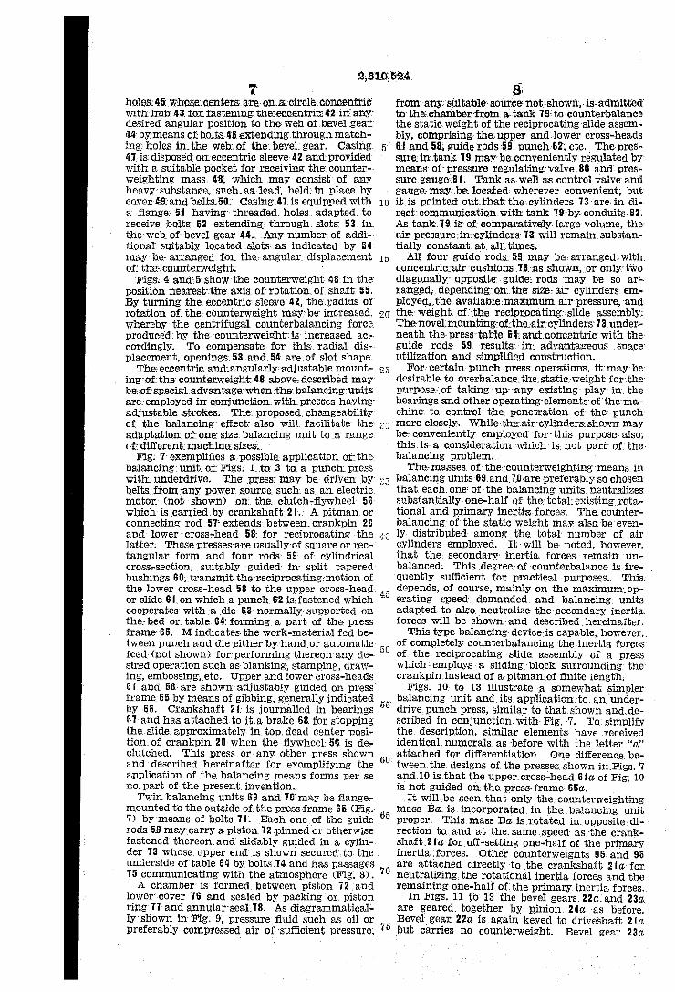
Fig. 7 exemplifies a possible application of the balancing unit of Figs; 1 to 3 to a punch press with underdrive. The press may be driven by belts from any power Source. Such as an electric motor (not shown) on the clutch-flywheel 56 which is carried by crankshaft2. A pitiinan, or connecting rod, 57 extends between crankpin 20 and lower cross-head, 58 for reciprocating the latter. These preSSes are usually of square or rec tangular form and four rods 59 of cylindrical Cross-section, suitably guided in split tapered bushings: 69, transmit the reciprocating motion of the lower cross-head 58 to the upper cross-head or slide 6 on which a punch. 62 is fastened which cooperates with a die. 63 normally. Supported on the bed or table 64 forming a part of the press frame 65. Mindicates the work-material fed be tWeen punch and die either by handlor automatic feed (not shown) for performing thereon any de sired operation such as blanking, stamping, draw ing, embOSSing, etc. Upper and lower cross-heads 6f and 58- are shown adjustably, guided on press frame: 65 by means of gibbing, generally indicated by 66. Crankshaft 2 is journalled in bearings 67 and has attached to it a brake 68 for stopping the slide approximately in top. dead center posi tion of crankpin 20 when the flywheel 56 is de clutched. This press. or any other press shown and described hereinafter for exemplifying the application of the balancing means forms perse no part of the present invention. Twin balancing units 69 and may be fange
mounted to the outside of the press frame 65 (Fig. 7) by means of bolts. T. Each one of the guide. rods 59 may carry a piston 72 pinned or otherwise fastened thereon, and slidably guided in a cylin der 3 whose upper end is shown secured to the underside of table 64 by bolts. T4, and has passages 5 communicating with the atmosphere (Fig. 8). A chamber is formed between piston 72 and
lower cover 6 and sealed by packing or piston ring TT and annular seal. 78. As diagrammatical ly shown in Fig. 9, pressure fluid such as oil or preferably compressed air of sufficient pressure,
O
5
20
60
65
70
75
8. from any suitable source: not shown, is admitted to the chambers from a tank 9: to counterbalance the static weight of the reciprocating slide assen's bly, comprising the upper and lower cross-heads 6, and 58, guide rods 59, punch.62, etc. The pres sure in tank 79 may be conveniently regulated by means of pressure regulating valve 88 and pres Sure-gauge:Bt. Tank.a.s. well as control valye and gauge: may be located wherever convenient, but it is pointed out...that the cylinders 3 are in di rect communication. With tank 9 by conduits. 82, AS tank.9 is of comparatively large volume, the air pressure in cylinders 3 will remain. Substan tially constant at all times.
All four guide rods. 59 may be, arranged with concentric air cushions 3 as shown, or only two diagonally opposite guide; rods, may be so ara ranged, depending on the size-air cylinders, em. ployed, the available:maximum air pressure, and the Weight. of the reciprocating-slide assembly. The novel mounting of the air-cylinders 3 under-. neath the press table 64; and concentric with the guide rods. 59, results in advantageous space Utilization and simplified construction.
For certain punch press, operations, it may be desirable to overbalance: the static weight for the purpose of taking up any existing play in the bearings and other operating elements of thema-. chine to control the penetration of the punch more-closely. While; the air cylinders shown may be conveniently employed for this purpose also, this is a consideration which is not part of the: balancing problem. - The-masses of the: counterweighting means in
balancing units: 69 and 0 are preferably so chosen that each. One: Of the balancing units neutralizes Substantially one-half of the total existing rota tional and primary inertia forces. The counter balancing of the static weight may also be even ly distributed among the total number of air cylinders employed. It will be noted, however, that the secondary inertia forces, remain un balanced. This degree of counterbalance is fre quently sufficient for practical purposes. This depends, of course, mainly on the maximum op erating Speed demanded and balancing units adapted to also neutralize the secondary inertia, forces Will be shown and described hereinafter.
This, type balancing device is capable, however, of completely couraterbalancing the inertia forces of the reciprocating slide assembly of a press which employs a sliding block surrounding the crankpin.instead of a pitman of finite length.
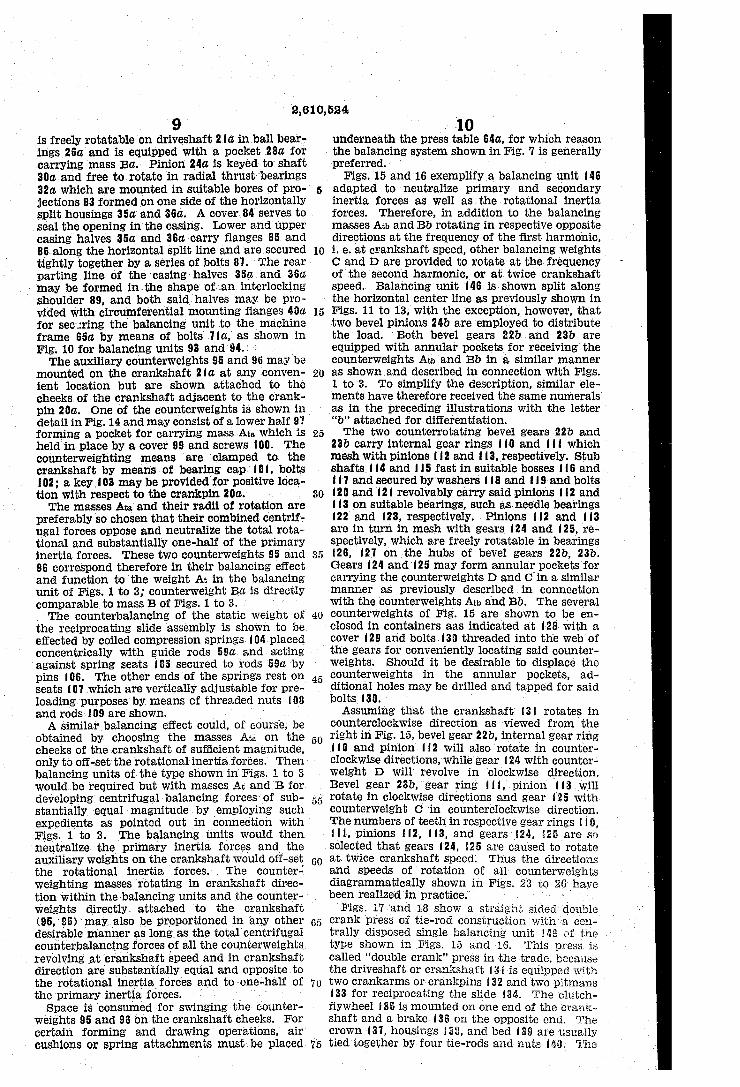
Figs. 10 to 13 illustrate a somewhat simpler balancing unit and its application to an under drive, punch press, similar to that shown and de Scribed in conjunction with Fig. 7. To simplify. the description, similar elements have received identical numerals as before with the letter 'a' attached for differentiation. One difference be tWeen the designs of the presses shown in Figs. 7 and 10 is that the upper cross-head 6 a. of Fig. 10 is not guided on the press-frame-65d.
It will be seen...that only the counterweighting maSS. Ba is incorporated in the balancing unit proper. This mass Ba is rotated in opposite di rection to and at the same speed as the crank shaft, 2 a for off-setting one-half of the primary inertia forces. Other counterweights 95, and 96 are attached directly to the crankshaft 2 a for neutralizing the rotational inertia forces and the remaining one-half of the primary inertia forces.
In FigS. 11 to 13 the bevel gears. 22a and 23a. are geared together by pinion 24a as before. Bevel gear. 22a is again keyed to driveshaft 2 a. but carries no counterweight. Bevel gear 23a.
2,610,524 9
is freely rotatable on driveshaft 2 la in ball bear ings 26a and is equipped with a pocket 28d for carrying mass Ba. Pinion 24d is keyed to shaft 30a, and free to rotate in radial thrust bearings 32d, which are mounted in suitable bores of pro jections 83 formed on one side of the horizontally split housings 35a, and 36a. A cover 84 serves to seal the opening in the casing. IOWer and upper casing halves 35a, and 36a carry flanges 85 and 86 along the horizontal split line and are Secured tightly together by a series of bolts 8. The rear parting line of the casing halves 35a, and 36a may be formed in the shape of an interlocking shoulder 89, and both said halves may be pro vided with circumferential mounting flanges 40a for securing the balancing unit to the machine frame 65a by means of bolts a, as shown in Fig. 10 for balancing units 93 and 94.2 The auxiliary counterweights 95 and 96 may be
mounted on the crankshaft 2 fa at any conven ient location but are shown attached to the cheeks of the crankshaft adjacent to the Crank pin 20a. One of the counterweights is shown in detail in Fig.14 and may consist of a lower half 9. forming a pocket for carrying maSS. Ata which is held in place by a cover 99 and screws fo). The counterweighting means are clamped to the crankshaft by means of bearing cap. 9, bolts 02; a key C3 may be provided for positive loca
tion with respect to the Crankpin 20d. The masses Ata and their radii of rotation are
preferably so chosen that their combined centrif ugal forces oppose and neutralize the total rota tional and substantially one-half of the primary inertia forces. These two counterweights 95 and 96 correspond therefore in their balancing effect and function to the Weight At in the balancing unit of Figs. 1 to 3 counterweight Ba is directly comparable to mass B of Figs. 1 to 3. . The counterbalancing of the static Weight of
the reciprocating slide assembly is shown to be effected by coiled compression springs. 04 placed concentrically with guide rods 59a and acting against Spring seats 5 secured to rods 59a by pins 06. The other ends of the Springs rest on seats 07 which are vertically adjustable for pre loading purposes by means of threaded nuts 08 and rods. O9 are shown. A similar balancing effect could, of course, be
obtained by choosing the masses Ata on the cheeks of the crankshaft of sufficient magnitude, only to off-set the rotational inertia, forces. Then balancing units of the type shown in Figs. 1 to 3 would be required but with masses. At and B for developing centrifugal balancing forces of sub stantially equal magnitude by employing such expedients as pointed out in connection with Figs. 1 to 3. The balancing units would then neutralize the primary inertia forces and the auxiliary weights on the crankshaft would off-set the rotational inertia forces. The counter weighting masses rotating in crankshaft direc tion within the balancing units and the counter weights directly. attached to the crankshaft (95, 96) may also be proportioned in any other desirable manner as long as the total centrifugal counterbalancing forces of all the counterweights revolving at crankshaft speed and in crankshaft direction are substantially equal and opposite to the rotational inertia forces and to one-half of the primary inertia forces. Space is consumed for swinging the counter
weights 95 and 96 on the crankshaft cheeks. For certain forming and drawing operations, air cushions Or Spring attachments must be placed
10
15
20
25
30
40
45
60
65
70
10 underneath the press table 64a, for which reason the balancing system shown in Fig. 7 is generally preferred.
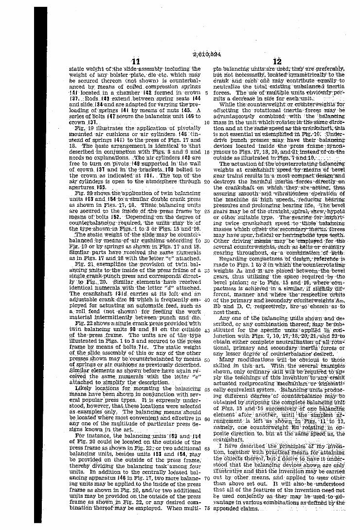
Figs. 15 and 16 exemplify a balancing unit 46 adapted to neutralize primary and secondary inertia forces as well as the rotational inertia forces. Therefore, in addition to the balancing maSSes Atb and Bb rotating in respective opposite directions at the frequency of the first harmonic, i. e. at crankshaft speed, other balancing weights C and D are provided to rotate at the frequency of the Second harmonic, or at twice crankshaft Speed. Balancing unit 46 is shown split along the horizontal center line as previously shown in Figs. 11 to 13, with the exception, however, that two bevel pinions. 24b are employed to distribute the load. Both bevel gears 22b and 23b are equipped with annular pockets for receiving the counter Weights Ath and Bb in a similar manner as shown and described in connection with Figs. 1 to 3. To simplify the description, similar ele ments have therefore received the same numerals as in the preceding illustrations with the letter "b' attached for differentiation. The two counterrotating bevel gears 22b and
23b carry internal gear rings fo and which mesh with pinions 2 and 3, respectively. Stub shafts 4 and 5 fast in suitable bosses 6 and f7 and secured by washers 8 and 9 and bolts 20 and 2 revolvably carry said pinions 2 and f3 on suitable bearings, such as needle bearings 22 and 23, respectively. Pinions 2 and 3 are in turn in mesh with gears 24 and 25, re Spectively, which are freely rotatable in bearings 26, 27 on the hubs of bevel gears 22b, 23b. Gears 24 and 25 may form annular pockets for carrying the counterweights D and C in a similar manner as previously described in connection With the counterweights Atb and Bb. The several Counterweights of Fig. 15 are shown to be en closed in containers aas indicated at 28 with a cover 29 and bolts. 30 threaded into the web of the gears for conveniently locating said counter Weights. Should it be desirable to displace the counterweights in the annular pockets, ad ditional holes may be drilled and tapped for said bolts. 30. ASSunning that the crankshaft 3 rotates in
counterclockwise direction as viewed from the right in Fig. 15, bevel gear 22b, internal gear ring
0 and pinion f2 will also rotate in counter clockwise directions, while gear 24 with counter Weight D will revolve in clockwise direction. Bevel gear 23b, gear ring if , pinion 3 will rotate in clockwise directions and gear 25 with counterweight C in counterclockwise direction. The numbers of teeth in respective gear rings 6, fi, pinions 2, 3, and gears 24, 25 are so Selected that gears 24, 25 are caused to rotate at twice crankshaft speed. Thus the directions and Speeds of rotation of all counterweights diagrammatically shown in Figs. 23 to 26 have been realized in practice. . . . .
Figs. 17 and 18 show a straight sided double Crank press of tie-rod construction with a cen trally disposed single balancing unit 4s of the type shown in Figs. 15 and 16. This press is called "double crank' press in the trade, because the driveshaft or crankshaft 3i is equipped with two crankarms or crankpins 32 and two pitmans 33 for reciprocating the slide 34. The clutch
flywheel f35 is mounted on one end of the crank shaft and a brake 36 on the opposite end. The Crown 37, housings 33, and bed 39 are usually tied together by four tie-rods and nuts 46. The
2,610,524 11
static weight of the slide" assembly including the weight of any bolster plate, die etc. which may be secured thereon (not shown) is counterbai anced by means of coiled compression Springs
- 4 - located in a chamber 42 formed in crown f37. Rods f43 extend between spring seats 44 andslide? 34 and are adapted for varying the pre loading of springs 4 by means of nuts 45. A series of bolts (47 secure the balancing unit {46 to crown f37. - . . . . .
Fig. 19 illustrates the application of pivotally mounted air cushions or air cylinders 48 (in stead of springs 4f) to the press of Figs. 17 and 18. The basic arrangement is identical to that described in conjunction with Figs. 8 and 9 and needs no explanations. The air-cylinders, 48 are free to turn on pivots 49 supported in the Wall of crown 37 and in the brackets...f50 bolted to the crown as indicated at if 5. The top of the air cylinders is open to the atmosphere through apertures. 55. . . . . . . . -
Fig.20 shows the application of tWinbalancing units 53 and 54 to a similar double crank preSS as shown in FigS. 17, 18. These balancing units are secured to the inside of the press frame by means of bolts, 52. Depending on the degree of counterbalancing required, the units may be of the type-shown in Figs...i. to 3 or Figs. 15 and i8. The static weight of the slidermay be counter
balanced by means of air cushions according to Fig.19 or by springs as shown in Figs. 17 and 18. Similar parts have received the same numerals as in Figs. 17 and 18 with the letter 'c' attached.
Fig. 21...exemplifies the provision of twin bal ancing units to the inside of the press fraine of a single crank-punch press and corresponds direct ly to Fig. 20. Similar elements have received identical numerals with the letter 'd' attached. The crankshaft 3id carries at its left end an adjustable crank disc 98 which is frequently-em ployed for actuating an automatic feed, such as a roll feed (not shown) for feeding the work material intermittently between punch and die.
Fig.22 shows a single crank press provided with twin balancing units. 90 and 9i on the outside of the press frame. The units are of the type illustrated in Figs, 1 to 3 and Secured to the press frame by means of bolts le. The static weight of the slide assembly of this or any of the other presses shown may be counterbalanced by means of springs or air cushions as previously described. Similar elements as shown before have again re ceived the same numerals with the letter “e' attached to simplify the description. . .
Likely locations for mounting the balancing means have been shown in conjunction with sev eral popular press types. It is expressly under stood, however, that these locations were selected as examples only. The balancing means should be located where most convenient and effective in any one of the multitude of particular-press de signs known in the art. . . . . .
For instance, the balancing units "f 53 and 54 of Fig. 20 could be located on the outside of the press frame as shown in Fig. 22; or two additional balancing units, besides units 53 and 54, may be provided on the outside of the press frame, thereby dividing the balancing task among four units. In addition to the centrally located bal ancing apparatus 46 in Fig. 17, two more balanc ing units may be applied to the inside of the press frame as shown in Fig. 20, and/or two additional units may be provided on the outside of the press frame as shown in Fig. 22, or any desired com bination thereof may be employed. When multi
5
20
25
30
5 5
60
65
70
75
12 ple balancing units are used, they are preferably, but not necessarily, located symmetrically to the crank and each one may-contribute-equally to neutralize the total existing unbalanced inertia, forces. The use of multiple units obviotisly-per mits a decrease in size for each unit. . . . . . . While the counterweight or counterweights for
offsetting the rotational inertia, forces may be advantageously combined with the balancing mass in the unit whichirotates in thiesame: direct tion and at the same speed as the crankshaft; this is not essential as exemplified in Fig.10: Under drive punch presses may have their balancing devices located inside the press framer Synori ymous to Figs. 17, 18, 20, and 21instead of on-t outside as illustrated in Figs. 7 and i0. . . . . . The actuation of the counterrotating 5alancing
weights at crankshaft speed by means of bevel gear trains results in a most compact design and destroys the harmful.iriertia forces directly on the crankshaft on which they are acting, thus assuring smooth and vibrationless operation of the machine at high speeds, reducing bearing pressures and prolonging bearing life. The bevel gears may be of the straight, spiral, skew hypoid or other suitable type. The gearing for impart: ing twice crankshaft speed to those balanieing masses which offset the secondary inertia forces may have spur, helical or herringborié-type teeth. Other driving means may be empleyed for the several counterweights, such as belts or ordinary gearing throughout, or a combination of both; Regarding compactness of design, reference is
made to Figs. to 3 in which the counterrotatirig Weights. At and B. are placed between the bevel gears, thus utilizing the space required by the bevel pinion; or to Figs.-15 and 16, where.com pactness is achieved in a similar, if slightly dif ferent, manner and where the respective orbits of the primary and Secondary Couriterweights Atb, Bb and D, C, respectively, are so chosen as to nest them. - - - -
Any one of the balancing units shown and de scribed, or any combination thereof, may be sub stituted for the specific units applied in cori junction with Figs. 7, 30,178,2021; and 22 to obtain either complete neutralization of all rota tional, primary and secondary inertia forces. Or any lesser degree-of counterbalanice desired. Many modifications will be obvious to those
skilled in this-art. With the several examples shown, only ordinary skill will be required to aps ply the teachings of this invention to any crank actuated reciprocating mechanism or kinemati cally equivalent system. Balancing units pro
obtained by stripping of Figs. 15 an s element after an rangement is left "as shown in Figs. namely, one counterweight Barotating posite direction to, but at thes?rrie'sfeet crankshaft. . . I have described the princi
to have it under stood that the balancing devices shown are only. illustrative and that the invention may be carried out by other means, and applied to-uses other. than above set out. It Will also-be-linderstood. that all of the features of the invention need not be used conjointly as they may be used to ad vantage in various edmbinations as defined by the appended claims. ... " - - . . . .

2,610,524 13
I claim: 1. Balancing means for mechanisms having a
driveshaft including eccentric or crank means as well as connecting rod means for reciprocating a slide comprising at least one pair of balancing masses, means for rotating Said masses in re spective opposite directions around said drive shaft at the frequency of the first harmonic, the mass rotating in driveshaft direction being of such magnitude and having a radius of rotation as to produce centrifugal forces adapted to oppose and neutralize the rotational inertia forces and substantially one-half of the primary inertia. forces, the mass rotating in opposite direction thereto being of such magnitude and having a radius of rotation as to oppose and neutralize the remaining one-half of the primary inertia, forces, auxiliary balancing masses, gearing means associ ated with said auxiliary masses and operatively connected with said rotating means for impart ing to said auxiliary masses a rotational speed around the driveshaft equal to the frequency of the second harmonic to oppose and neutralize the secondary inertia, forces.
2. A balancing apparatus of the character de scribed comprising a pair of bevel gears disposed on the crankshaft of a machine to be counter balanced, a counterweighting mass associated with each of said bevel gears, means for rotating said bevel gears with their associated counter weighting masses in respective opposite directions at the speed of the crankshaft, said counterro tating masses being adapted to create centrifugal counterbalancing forces of substantially equal magnitude and such respective directions as to oppose and neutralize the primary inertia, forces, other counterweighting masses located diametri cally opposite the crank of the crankshaft and adapted to be rotated with the latter and to neu tralize the rotational inertia forces, an internal gear ring Secured to each of said bevel gears, a gear freely rotatable on the respective hubs of each of Said bevel gears, a pinion meshing with each of Said aSSociated internal gear rings and gears adapted to rotate said gears at twice crank shaft speed, and a counterweight secured to each of said gears for counterbalancing the Secondary inertia, forces, said counterweighting masses and counterweights being coincident at bottom dead center when the crankshaft is at top dead center.
3. A counterbalancing device for a punch press having a frame, a slide, a driveshaft including eccentric means for reciprocating said slide, com prising a housing secured to said frame, at least two balancing weights inclosed in said housing,
5
10
5
20
30
40
45
50
55
14 the first of said balancing weights being con structed to neutralize one-half of the unbalanced primary inertia, forces as well as the rotational inertia forces, the second of said balancing Weights being constructed to neutralize the re maining one-half of the unbalanced primary inertia, forces; a first bevel gear, means for se curing said first balancing weight to said first bevel gear in a radially displaced position with respect to said driveshaft for counteracting the rotational inertia forces plus one-half of the primary inertia forces, a second bevel gear, means for securing said second balancing weight to said second bevel gear in a radially displaced position With respect to said drive shaft for counteract ing the remaining one-half of the primary inertia forces, both said bevel gears being located within said housing in face-to-face and Spaced relation and disposed coaxially with said driveshaft; an idler pinion meshing with both said bevel gears, and means for fastening said first bevel gear to said driveshaft to rotate said bevel gears with their respective balancing weights in opposite di rections but in Synchronism with said driveshaft.
4. A counterbalancing device according to claim 3, including an internal gear ring secured to each of said bevel gears, a gear freely rotatable on the respective hubs of each of said bevel gears, a pinion meshing with each of Said cooperating internal gear rings and gears for rotating said gears at twice driveshaft speed, an auxiliary bal ancing weight secured to each of said gears for counterbalancing the secondary inertia forces, Said balancing weights being coincident at bottom dead center when the driveshaft is at top dead center.
FREDERCKK. MAUSSNEST.
REFERENCES CITED The following references are of record in the
file of this patent: UNITED STATES PATENTS
Number Name Date 1,226,832 Webber ------------ May 22, 1917 2,127,317 Welch ------------- Aug. 16, 1938 2,182,988 Iseler -------------- Dec. 12, 1939 2,183,467 Sarazin ------------ Dec. 12, 1939 2,188,482 Parks -------------- Jan. 30, 1940 2,244,428 O'Leary ------------ June 3, 1941 2,248,182 Mateer -------------- July 8, 1941 2,284,515 Criswell ----------- May 26, 1942 2,293,915 Patterson ---------- Aug. 25, 1942 2,366,033 Johnstone --------- Dec. 26, 1944 2,428,924. Albertson ---------- Oct. 14, 1947