september 2002 file: epas 69 modeling architecture and ... · september 2002 file: epas 69 modeling...
TRANSCRIPT

208 Harbor Drive • Stamford, CT 06912-0061 • (203) 973-6700 • Fax (203) 359-8066 • metagroup.com Copyright © 2002 META Group, Inc. All rights reserved.
September 2002 File: EPAS 69
Modeling Architecture and Infrastructure Planning: Domains to Patterns and Beyond Enterprise Planning & Architecture Strategies Bruce Robertson FOCAL POINT With numerous planning activities executed by day-to-day or per-project infrastructure planners and enterprise architects, IT organizations (ITOs) must coordinate and, in fact, consolidate their approaches to modeling technical standards, particularly for infrastructure — from architecture through technology, product, and configuration information. Although many architectural methodologies have used a traditional domain model for categorizing technology, evolving infrastructure planning tactics can enhance such methodologies by highlighting end-to-end models (infrastructure patterns) and shared infrastructure top-to-bottom models (infrastructure services) as key concepts for technology planning. These approaches must be clarified and unified immediately (2002) to deliver consistent and complete enterprise technical architecture (ETA) and infrastructure planning solutions. Medium-term, periodic standards-making, and per-project (sometimes standards-breaking) processes and behavior must also be unified (2003/04), while long-term iterations of strategic planning processes must update models and frameworks (2005/06), along with specific strategies and tactics aligned with the models. CONTEXT To reduce the complexity of planning infrastructure, most organizations standardize to reduce (or at least stabilize) various infrastructure components actually implemented, and to enhance future adaptability and agility. Such standardization helps reduce the cost of operating too many different components, simplify contract management and negotiations, and speed decision making on a per-project basis while minimizing the cost to change things later. Unfortunately, many ITOs have multiple approaches to standardizing architecture, infrastructure, and other technology areas. Often, different IT constituencies drive separate planning activities. However, this duplicative approach is more than a waste; it is a roadblock to achieving valuable standardization that can be useful in practical per-project behavior within the daily activities. Certainly, all IT constituencies resist standardization, particularly due to project deadline and budget pressure. Yet, this must drive the need to communicate the values of standardizing better even as it drives a more effective integration of standardization and planning functions into ongoing day-to-day operations. Architects and infrastructure planners or engineers (especially) must unify or consolidate their structured technology models, even if they (or other distributed business-unit cases of infrastructure planners) continue to plan certain aspects of standards separately. In most organizations, current technology planning activities are generally splintered among per-project engineers, technology experts, and enterprise architects, which leads to disparate solution strategies. Unifying such activities, either into completely centralized or more complex federated approaches, will yield significant solution delivery synergy within any organization. Most organizations will move to more integrated and/or consolidated models for planning within two years, with different aspects of value and synergy (cost estimation, design elegance, speed of delivery, etc.) being exploited or enabled during this transition period. Longer term, more unified planning approaches will extend beyond technology mappings into repeatable application as well as technical and operational service designs while exploiting information synergies (including leveraging Web services and other technology trends for e-business infrastructure and application solutions).
META Trend: Through 2005, as adaptable infrastructure becomes increasingly critical to business success, infrastructure development (ID) priorities will evolve from overhead cost estimation to business investment planning that balances infrastructure agility, robustness, and affordability. To compete for investment dollars, ID organizations will employ techniques like infrastructure pattern matching (design), infrastructure impact assessment (planning), predictive cost modeling (budgeting), application subscriptions (packaging), and account management (customer service).
208 Harbor Drive • Stamford, CT 06912-0061 • (203) 973-6700 • Fax (203) 359-8066 • metagroup.com File: EPAS Practice 69 Copyright © 2002 META Group, Inc. All rights reserved.
2
Aligning Technology Models Architects and infrastructure planners often plan separately for standards and solutions. Sometimes this is because they are planning at different levels with different scopes (e.g., architects with a 3-5-year future view, infrastructure planners with a 0-18/24-month view). Moreover, architects plan more broadly than typical bottom-up engineering or infrastructure planning groups, focusing on business alignment, information, and application or solution strategies — not just on technical architecture. Sometimes this is because, in larger organizations, the groups are separated just enough to evolve their own approaches. Many times, as the focus narrows to technology planning, these disparate groups are planning the same things, but using different terms to define their goals. Any ITO planning infrastructure must unite its views of architecture and infrastructure planning technology models to proceed with standardizing technologies at a proper level, as well as to better handle per-project use of technology standards (see Figure 1). Beyond technology architecture models, these two groups (as well as others in the IT organization) must align their processes as well and focus on higher-level explicit business strategy integration.
Components: Starting at the Bottom One key goal of both architectural and infrastructure planning or engineering technology models is to reduce complexity. Of course, both groups have other goals — increasing flexibility or adaptiveness, shortening time to market, holistically delivering integrated solutions to the enterprise, etc. Still, reducing complexity is a key driver of using technology architecture models in particular. When designing more distributed and client/server (and now n-tier and service-oriented) architectures, many items must be organized properly. These items are labeled components — not as application developers typically define them (segments of code), but as the largest individual physical items that are put together in a design. Infrastructure planners typically create pictures with a drawing tool (e.g., PowerPoint, Visio) to show the designs. Such components can have many attributes, including principles that govern choices about technologies and products used to implement them. In any ITO, the simple list of technologies used or to be used must be well articulated and shared across planning groups, regardless of their scope. META Group provides a starter kit that lists an sample component catalog and can assist in augmenting such a catalog given recent changes in technologies and products, as well as particular customer goals and approaches (see excerpt in Figure 2). This starter kit specifies common domain memberships as well as key service and pattern mappings, but these can be adjusted to match a given organization’s approach.
Figure 1 — Infrastructure Planning Defined
Source: META Group
The objective of infrastructure planning is to determine the scope, scale, and design of infrastructure necessary to provide application service levels required by the business in the short, medium, and long term.

208 Harbor Drive • Stamford, CT 06912-0061 • (203) 973-6700 • Fax (203) 359-8066 • metagroup.com File: EPAS Practice 69 Copyright © 2002 META Group, Inc. All rights reserved.
3
For each technology component, detailed technology expertise must be provided. Indeed, a given infrastructure professional should be identified as the definitive technology expert. To supplement the efforts of in-house experts, outside expertise is often warranted. Sometimes, the expert or expertise is from an operations group (for more mature components, such as networking items); at others, it is from an architecture group (for less mature components, such as middleware). Other organizational possibilities abound, not to mention duplication of such experts and expertise in different parts of more distributed organizations. Clearly, defining which person, group, or virtual team is responsible for expertise on a component level is critical. However, there are other levels of expertise — less deep but broader — that are required to manage or design other models (patterns, services, etc.). For any component, further detailed information could be provided, such as rationales for key architectural or technology requirements, product requirements, product choices, configuration details, etc. Many architects augment this with a ranking system by component for which choices are strategic (strongly recommended for new implementations), tactical (acceptable but not recommended for new implementations), legacy (currently installed and still requiring support), and sunset (currently installed and marked for early retirement, if possible). Such value markings (some just use colors, such as green, yellow, or red, or stock portfolio metaphors, such as strong buy, buy, hold, or sell) help distinguish what decisions should be made on a per-project level about choosing the right implementation of the component for a project. The Problem With Component Models However, both architecture and infrastructure planning approaches recognize that just a huge list of many items and standards does not help enough. Such a large undifferentiated list is not organized enough, now that there are so many of these components to get right for each solution (i.e., each application) that must be delivered. Each time a solution is assembled — to roll out an application, for instance — there are many components to pick from and assemble together appropriately. Moreover, there are certain guiding principles that are not for just one component that must also be understood; these architectures and strategies go beyond a component view. Such component models are not sufficient for either day-to-day per-project use or longer-term strategic planning. Domains: Establishing Buckets of Components Consequently, most organizations have suggested higher-level aggregate models to better organize this morass of components. The traditional architecture approach organized components into domains based on technology or organizational similarities. Such domains include network, security, hardware/operating system platform, middleware, etc. Similarly, infrastructure planners focused on models for infrastructure planning that specified an approach called a platform model — a single stack of layers that describes the whole of the infrastructure required for any solution. We believe the goals of these differently labeled models are so similar that they should not be named differently. Infrastructure planners must adopt the domain term to describe this technology or organizational affinity model for grouping technology components. Even if the views are not exactly the same, they should be easy to relate. The resulting integrated view could look like Figure 3 (the domain approaches of a typical ETA and infrastructure planners are easily mapped, along with definitions and sample components), depending on which exact domains a given organization might have chosen.
Figure 2 — META Group Component Catalog (Single Component Example Excerpt)
Source: META Group
Domain Component Name Description Sample Product/Vendor
Network Network load balancer
Switches or appliances that fail over and balance traffic load across sets of servers, firewalls, and caches in both server load balancing and global or site load balancing scopes.
Appliance/hardware: F5 Networks, Cisco (LocalDirector, ArrowPoint), Nortel (Alteon), Extreme, Foundry, Radware Software: Microsoft, IBM

208 Harbor Drive • Stamford, CT 06912-0061 • (203) 973-6700 • Fax (203) 359-8066 • metagroup.com File: EPAS Practice 69 Copyright © 2002 META Group, Inc. All rights reserved.
4
Figure 3 — Mapping Typical Enterprise Technology Architecture (ETA) Domains to META Group’s Infrastructure Planning (IP) Domain Starter Kit
Source: META Group
Typical ETA Domain
IP Domain
Starter Kit Definition Sample
Components
Application Application Application technology (not business logic or function), including specific development tools, packages, etc. Sometimes, applications are also viewed as infrastructure, but the application code for business logic is not included as other infrastructure; some planners include office productivity tools (office, e-mail, etc.) as infrastructure because they are so completely standardized and stable that they are no longer managed or planned by application developers.
• Application development tools (Java development tools, Visual Basic, C++, etc.), debugging and testing tools, compilers, etc.
• Actual applications are better described not as technology, but as solution domains and/or components; architects should flesh those items out in an enterprise solution architecture (and/or application portfolio structure).
Middleware API Technology that models new APIs or techniques that ensure best API use.
Intra-API, inter-API, and infra-API services (including UML modeling tools such as Rational Rose), including Web services technologies.
Middleware Presentation Technology that provides points of interaction or different presentations of data.
Web server, interactive voice response, and WAP server.
Middleware Application server
Application server software that executes business logic.
Application server (e.g., IBM WebSphere, BEA WebLogic).
Middleware Integration server
Enterprise application integration software that connects different applications together, reformatting and routing data as necessary.
Integration server, inter-enterprise integration server.
Data and object management
Database server
Software that stores data for efficient record and field-level retrieval, along with data access and gateway functions.
DBMS, data access middleware.
Platform Platform (server/client HW/OS)
Server as well as client hardware, operating system, and high-availability (HA) solutions.
Application server HW, OS, and HA; Web server HW, OS, and HA; desktop choices for this as well.
Platform Storage Hardware, including disk and tape approaches, along with software for backup and recovery.
Storage server, business continuance SW.
Network Network Hardware, software, and services providing connectivity among devices.
WAN access product (router), Ethernet switch.
Security Security Hardware, software, and services providing authentication, authorization, encryption, and other threat-protection functions.
Security solutions, such as Web SSO, directory servers, and firewalls.
Management Management Hardware, software, and services providing management of components and services.
Management solutions, including element managers (that could have been noted in separate domains but collected here) and frameworks (HP OpenView, etc.), as well as service-level management solutions (SLA monitors, etc.) that apply to the whole infrastructure across all domains.

208 Harbor Drive • Stamford, CT 06912-0061 • (203) 973-6700 • Fax (203) 359-8066 • metagroup.com File: EPAS Practice 69 Copyright © 2002 META Group, Inc. All rights reserved.
5
META Group’s domain architecture template delineates the following attributes for a domain: • States the definition of the domain architecture and related domain architectures • Points the reader to other related domain architectures • Provides an overview describing the domain architecture • Identifies the IT or technology trends relevant to the environment • Describes the global design principles associated with the domain architecture • Describes principles, trends, technologies, standards, products, and configurations for each major area
included in this domain architecture Infrastructure planners should use this structure when working out domain standards details, with a starter kit as noted in Figure 3. Similar attributes should apply to pattern and service designs. A Note on Principles Architects often use an ETA approach, which is directly negotiated with the business to define key business driven principles. Although infrastructure planners may not take a fully top-down ETA (and higher-level top-down planning) approach, as with any more practical and near-term delivery-focused design process, infrastructure planners should further define levels of support for such top-down principles (even if they did not themselves derive them); they should also add new bottom-up or technology-driven principles. In some cases, principles can be observed in actual decisions for near-term requirements, but in some cases they must be left behind. Either way, this leverage should be explicitly documented in such domain (and other model) standards. On the other hand, infrastructure planners use a different technique to map more indirectly to business vision, interpreting that business vision primarily via the applications to be deployed for the business. Given this focus, infrastructure planners have increasingly moved to a new model to reflect the key relationship of infrastructure to applications called infrastructure patterns. However, the downside of this application-centric approach is it is assumes that a process is in place to ensure that the applications and projects implementing them are themselves explicitly tied to enabling the business vision. Unfortunately, bad application choices will naturally lead to poor infrastructure investments. To avoid this, the full architectural approach must be applied from the top down. Both architects and infrastructure planners have one key design principle to work from: design for change, which is the only item that can always be counted on to be a key requirement. This should give the designer flexibility to optimize solutions later for cost, performance, scale, and other attributes. Infrastructure planners describe this methodology in pattern and service-oriented architecture designs, including a generalized service model as well as specific cases involving Web services. The Problem With Domain Models Although domains are useful concepts for planning, they often lead to stovepipes of design. Properly focused architectural efforts should unify across domains via conceptual architecture and appropriate enterprise principles, driving down to domain-level principles based on business goals. Unfortunately, many architectural efforts have practically ignored (or never recognized) this and have gone directly to technology domain architectures, thus ending up with stovepipes of design. The organizations that have tried this from the bottom up have generated a similarly stovepiped view. Thus, planning technology has not had a holistic end-to-end view. Consequently, although domain models are necessary to effective architecture, they are not sufficient. In particular, designers (architects or engineers) must articulate models for more useful expression of goals of application delivery and shared service delivery, rather than just as technology with little relevance to any kind of business value. An outcome of the stovepipe domain approach is that major sets of components are optimized, but there is no optimization of all these components together for general solutions that map directly to application requirements. Components from each domain will be needed to define a complete end-to-end solution. Sometimes, optimizing these components independently can lead to overprovisioned systems. For example, server planners might design high availability at a server level, yet network designers might include network load balancing to support redundant servers. Clearly, investments in both high-availability approaches can waste effort and money. More often, it leads to miscommunication between the different architects or planners; thus, there are gaps between parts that are not well understood. This leads to implementations that have significant problems to correct for all the independently designed parts to work together. To overcome

208 Harbor Drive • Stamford, CT 06912-0061 • (203) 973-6700 • Fax (203) 359-8066 • metagroup.com File: EPAS Practice 69 Copyright © 2002 META Group, Inc. All rights reserved.
6
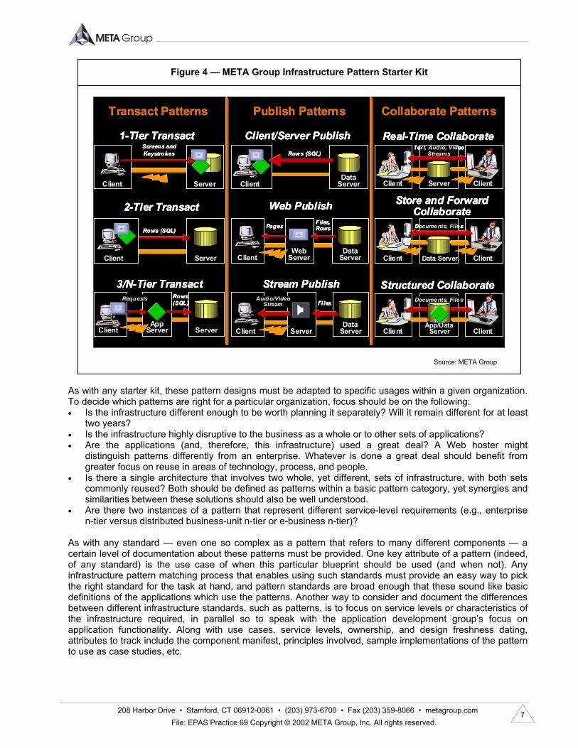
this, infrastructure planners define a more direct end-to-end solution model (for infrastructure) that maps components from all required domains. This end-to-end solution model is called an infrastructure pattern. Infrastructure Patterns: Mapping Across Domain Gaps During a project implementation, infrastructure planners must describe all the components (and services) required for a given application. As such, they are sufficient for a single application deployment. However, because many applications can and should leverage very similar designs, an infrastructure pattern model is designed to serve as the standard blueprint for a set or class of applications that all leverage a very similar or single exact infrastructure design. For example, there is a difference between the hundreds of unique blueprints for hundreds of custom-designed houses and a single blueprint used for hundreds of tract houses in a housing development. Assuming both sets of houses meet the essential needs of their homeowners, which set of houses will have the faster construction time, lower construction costs, and lower long-term total cost of ownership? Such standardized blueprints for complete infrastructure delivery plans are more easily reused. Interactions between components (and domains) should be predefined and well understood, particularly after a few implementations of the pattern are completed. This provides more confidence in the value of the blueprint in reducing per-project implementation time (fewer choices, less new testing to confirm integration, etc.). In a way, this is just extending the multicomponent bundles that most organizations become comfortable with (e.g., Oracle on Solaris on particular Sun SPARC boxes), and repeating them. Much like application packages, such infrastructure bundles are packaged infrastructure. The infrastructure pattern approach pushes this grouping approach to a full end-to-end model for a whole application (or set of similar applications). Granted, any given implementation will have differences, but generally many can follow a similar model. Even then, the goal is 80/20; most of the time, this reusable approach will work. However, a custom design will sometimes be required. Even then, this should be based on reusable components and services that relevant pattern designs also leverage. META Group has assessed common application requirements and generated a starter kit for infrastructure patterns (see Figure 4 as well as GNS Delta 911 for more details on this particular third-generation pattern set). However, along with the models themselves, the process by which such patterns can be best leveraged to ensure reuse and value must be defined.
208 Harbor Drive • Stamford, CT 06912-0061 • (203) 973-6700 • Fax (203) 359-8066 • metagroup.com File: EPAS Practice 69 Copyright © 2002 META Group, Inc. All rights reserved.
7
As with any starter kit, these pattern designs must be adapted to specific usages within a given organization. To decide which patterns are right for a particular organization, focus should be on the following: • Is the infrastructure different enough to be worth planning it separately? Will it remain different for at least
two years? • Is the infrastructure highly disruptive to the business as a whole or to other sets of applications? • Are the applications (and, therefore, this infrastructure) used a great deal? A Web hoster might
distinguish patterns differently from an enterprise. Whatever is done a great deal should benefit from greater focus on reuse in areas of technology, process, and people.
• Is there a single architecture that involves two whole, yet different, sets of infrastructure, with both sets commonly reused? Both should be defined as patterns within a basic pattern category, yet synergies and similarities between these solutions should also be well understood.
• Are there two instances of a pattern that represent different service-level requirements (e.g., enterprise n-tier versus distributed business-unit n-tier or e-business n-tier)?
As with any standard — even one so complex as a pattern that refers to many different components — a certain level of documentation about these patterns must be provided. One key attribute of a pattern (indeed, of any standard) is the use case of when this particular blueprint should be used (and when not). Any infrastructure pattern matching process that enables using such standards must provide an easy way to pick the right standard for the task at hand, and pattern standards are broad enough that these sound like basic definitions of the applications which use the patterns. Another way to consider and document the differences between different infrastructure standards, such as patterns, is to focus on service levels or characteristics of the infrastructure required, in parallel so to speak with the application development group’s focus on application functionality. Along with use cases, service levels, ownership, and design freshness dating, attributes to track include the component manifest, principles involved, sample implementations of the pattern to use as case studies, etc.
Figure 4 — META Group Infrastructure Pattern Starter Kit
Source: META Group
Transact Patterns Publish Patterns Collaborate Patterns
2-Tier Transact
Server
Rows (SQL)
Client
Client/Server Publish
DataServer
Rows (SQL)
Client
Stream Publish
Client Server
Fi les
DataServer
Audio/VideoStream
1-Tier Transact
Server
Screens andKeystrokes
Client
Web Publish
Client
Files,Rows
DataServer
Pages
WebServer
3/N-Tier Transact
Client
Rows(SQL)
Server
Requests
AppServer
Structured Collaborate
ClientApp/Data
Server Client
Docume nts, File s
Real-Time Collaborate
Server
Text, Audio, VideoStreams
Client Client
Store and ForwardCollaborate
Client Data Server
Docume nts, File s
Client
Transact Patterns Publish Patterns Collaborate Patterns
2-Tier Transact
Server
Rows (SQL)
Client
2-Tier Transact
Server
Rows (SQL)
Client
Client/Server Publish
DataServer
Rows (SQL)
Client
Client/Server Publish
DataServer
Rows (SQL)
Client
Stream Publish
Client Server
Fi les
DataServer
Audio/VideoStream
Stream Publish
Client Server
Fi les
DataServer
Audio/VideoStream
1-Tier Transact
Server
Screens andKeystrokes
Client
1-Tier Transact
Server
Screens andKeystrokes
Client
Web Publish
Client
Files,Rows
DataServer
Pages
WebServer
Web Publish
Client
Files,Rows
DataServer
Pages
WebServer
3/N-Tier Transact
Client
Rows(SQL)
Server
Requests
AppServer
3/N-Tier Transact
Client
Rows(SQL)
Server
Requests
AppServer
Structured Collaborate
ClientApp/Data
Server Client
Docume nts, File s
Structured Collaborate
ClientApp/Data
Server Client
Docume nts, File s
Real-Time Collaborate
Server
Text, Audio, VideoStreams
Client Client
Real-Time Collaborate
Server
Text, Audio, VideoStreams
Client Client
Store and ForwardCollaborate
Client Data Server
Docume nts, File s
Client
Store and ForwardCollaborate
Client Data Server
Docume nts, File s
Client
208 Harbor Drive • Stamford, CT 06912-0061 • (203) 973-6700 • Fax (203) 359-8066 • metagroup.com File: EPAS Practice 69 Copyright © 2002 META Group, Inc. All rights reserved.
8
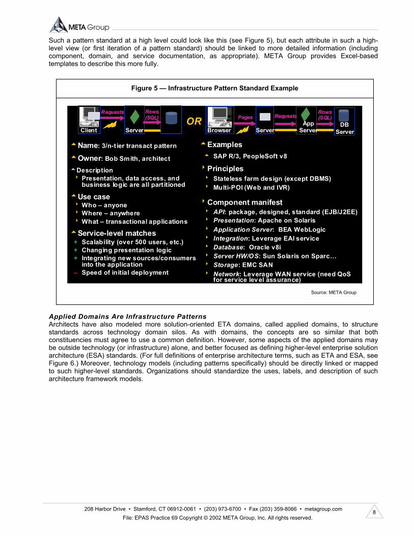
Such a pattern standard at a high level could look like this (see Figure 5), but each attribute in such a high-level view (or first iteration of a pattern standard) should be linked to more detailed information (including component, domain, and service documentation, as appropriate). META Group provides Excel-based templates to describe this more fully.
Applied Domains Are Infrastructure Patterns Architects have also modeled more solution-oriented ETA domains, called applied domains, to structure standards across technology domain silos. As with domains, the concepts are so similar that both constituencies must agree to use a common definition. However, some aspects of the applied domains may be outside technology (or infrastructure) alone, and better focused as defining higher-level enterprise solution architecture (ESA) standards. (For full definitions of enterprise architecture terms, such as ETA and ESA, see Figure 6.) Moreover, technology models (including patterns specifically) should be directly linked or mapped to such higher-level standards. Organizations should standardize the uses, labels, and description of such architecture framework models.
Figure 5 — Infrastructure Pattern Standard Example
Source: META Group
tName: 3/n-t ier transact pattern
tOwner: Bob Smith, architect
tDescription8 Presentation, data access, and
business logic are all part itioned
tUse case8Who – anyone8Where – anywhere8What – transactional applications
tService-level matches+ Scalability (over 500 users, etc.)+ Changing presentation logic+ Integrating new sources/consumers
into the application– Speed of initial deployment
tExamplest SAP R/3, PeopleSoft v8
8Principles8 Stateless farm design (except DBMS)8 Multi-POI (Web and IVR)
8Component manifest8 API: package, designed, standard (EJB/J2EE)8 Presentation: Apache on Solaris8 Application Server: BEA WebLogic8 Integration: Leverage EAI service8 Database: Oracle v8i8 Server HW/OS: Sun Solaris on Sparc…8 Storage: EMC SAN8 Network: Leverage WAN service (need QoS
for service level assurance)
ORRequests
Server
Rows (SQL)
Client
Requests
Server
Rows (SQL)
ClientClient
Pages
Server
Rows (SQL)
BrowserApp
Server
RequestsPages
Server
Rows (SQL)
BrowserBrowserApp
Server
RequestsDB
Server

208 Harbor Drive • Stamford, CT 06912-0061 • (203) 973-6700 • Fax (203) 359-8066 • metagroup.com File: EPAS Practice 69 Copyright © 2002 META Group, Inc. All rights reserved.
9
Mapping Technical Architecture (and Infrastructure) to Applications A key goal of the infrastructure patterns is to model the gap between traditional architecture domains and the application portfolio (or, as some architects describe it, the ESA). Looking at things from the top down (see Figure 7), most architects focus on much that is not enterprise technical architecture, including business architecture, information architecture, and application portfolio, as well as program management and general business planning and strategy.
Figure 6 — Enterprise Architecture Definitions
Source: META Group
For more information, see EPAS META Practice 62. • Enterprise architecture (EA): A top-down, business-strategy-driven process that coordinates the
parallel, internally consistent development of enterprise business, information, technology, and solution architectures (EBA, EIA, ETA, ESA). It represents the holistic expression of the enterprise’s key business, information, application, and technology strategies as well as their impact on business functions and processes. Conducted within an appropriate, collaborative organization/governance context, EA artifacts consist of a common requirements vision (CRV), a conceptual architecture (CA), as well as current- and future-state models of four key components: EBA, EIA, ETA, and ESA.
• Enterprise business architecture (EBA): A business-vision-driven, disciplined process that decomposes the enterprise’s business strategies, the assets and processes required to execute them, and their impact on business functions. Artifacts of the EBA consist of a CRV, a CA, as well as current-and future-state models of business activity that articulate the extended enterprise value chain. EBA is implemented through the enterprise’s EIA, ETA, and ESA, and defines the business design for sustainable competitive advantage.
• Enterprise information architecture (EIA): An EBA-driven, disciplined process that details the enterprise’s information strategies, its extended information value chain, and their impact on technical architecture. A “mirror image” of the EBA, artifacts of the EIA consist of a CRV, a CA, as well as current-and future-state information models that describe the extended information value chain; delineate the key information artifacts of business events, models, and information flows; provide logically consistent information management principles; and enable rapid business decision making and information sharing.
• Enterprise solution architecture (ESA): An EIA-driven collection of integrated application systems required to satisfy business information needs, including the existing and planned inventory of applications and components, complete with relationships to supported information and business processes as well as engineered linkages to ETA and infrastructure services.
• Enterprise technical architecture (ETA): An EIA-driven, disciplined process that details the enterprise’s technology strategies, its extended technology linkages, and their impact on program/project initiatives. Consistent with the EBA and EIA, artifacts of the ETA consist of a CRV, a CA set of guiding principles, as well as current- and future-state models of the enterprise’s infrastructure and technology platforms. The ETA enables rapid engineering, solution development, and technical innovation.

208 Harbor Drive • Stamford, CT 06912-0061 • (203) 973-6700 • Fax (203) 359-8066 • metagroup.com File: EPAS Practice 69 Copyright © 2002 META Group, Inc. All rights reserved.
10
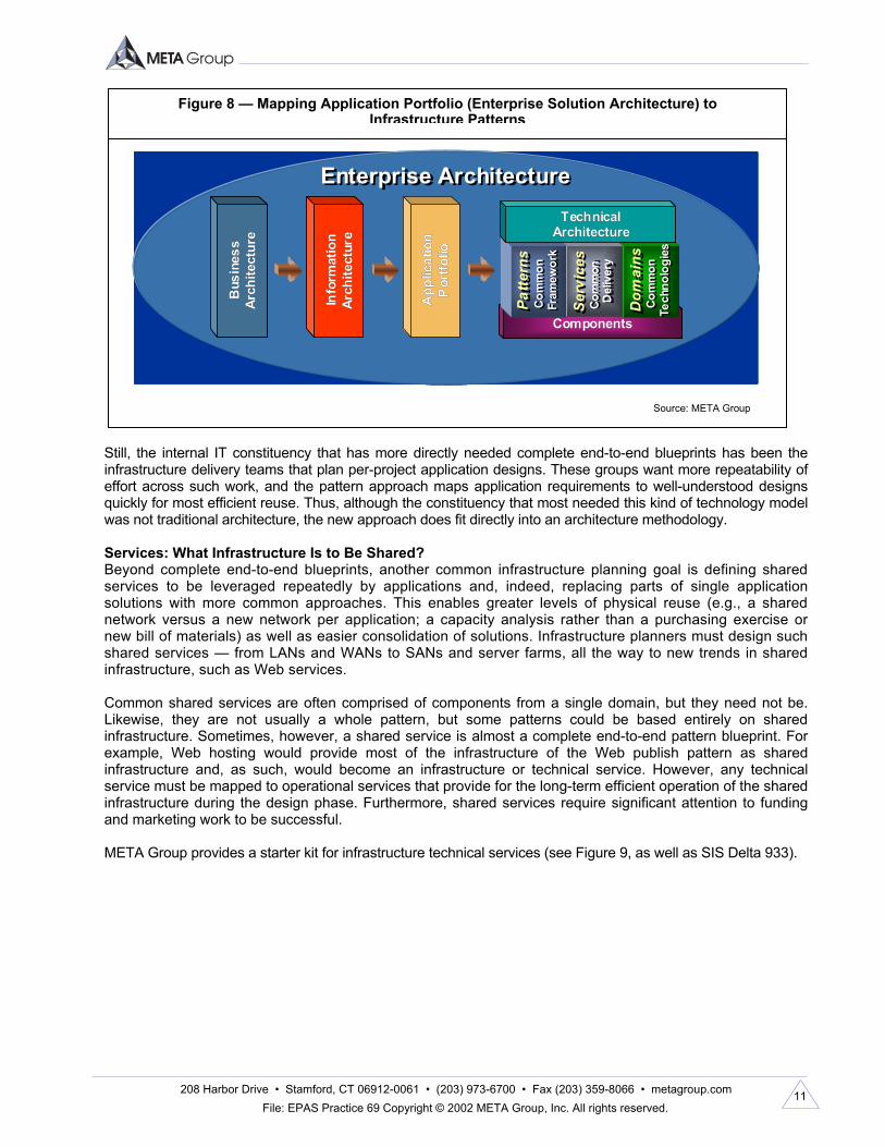
Nevertheless, within the technical architecture area, models for domains, patterns, and services are directly specified. Although architects designate that this modeling should be done, infrastructure planners often directly complete that portion of the architecture (and technology experts, assisted by architects). Organizations must be clear about the roles of architects, infrastructure planners, engineers, and technical experts at various levels, particularly regarding which roles own or influence which kinds of models. Indeed, the pattern approach models the connection of the ETA to the application portfolio or ESA constructs. Patterns represent the direct mapping of applications or solutions into technology and/or infrastructure as complete end-to-end solutions (see Figure 8). Patterns make this mapping explicit.
Figure 7 — Relating Architecture Goals and Models to Patterns, Services, and Domains
Source: META Group
ServicesServicesCommon
DeliveryCommon De livery
PatternsPatternsCommon
FrameworkCommon Fra mework
DomainsDomainsCommon
Te chnologiesCommon
Technologie s
Tech
nica
lTe
chni
cal
Arch
itect
ure
Arch
itect
ure
Appl
icat
ion
Appl
icat
ion
Portf
olio
Portf
olio
Info
rmat
ion
Info
rmat
ion
Arch
itect
ure
Arch
itect
ure
Busi
ness
Busi
ness
Arch
itect
ure
Arch
itect
ure
Planning and Strategy
Planning and Strategy
EnterpriseArchitectureEnterprise
Architecture
EnterpriseProgram
Management
EnterpriseProgram
Management
208 Harbor Drive • Stamford, CT 06912-0061 • (203) 973-6700 • Fax (203) 359-8066 • metagroup.com File: EPAS Practice 69 Copyright © 2002 META Group, Inc. All rights reserved.
11
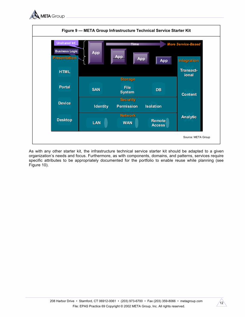
Still, the internal IT constituency that has more directly needed complete end-to-end blueprints has been the infrastructure delivery teams that plan per-project application designs. These groups want more repeatability of effort across such work, and the pattern approach maps application requirements to well-understood designs quickly for most efficient reuse. Thus, although the constituency that most needed this kind of technology model was not traditional architecture, the new approach does fit directly into an architecture methodology. Services: What Infrastructure Is to Be Shared? Beyond complete end-to-end blueprints, another common infrastructure planning goal is defining shared services to be leveraged repeatedly by applications and, indeed, replacing parts of single application solutions with more common approaches. This enables greater levels of physical reuse (e.g., a shared network versus a new network per application; a capacity analysis rather than a purchasing exercise or new bill of materials) as well as easier consolidation of solutions. Infrastructure planners must design such shared services — from LANs and WANs to SANs and server farms, all the way to new trends in shared infrastructure, such as Web services. Common shared services are often comprised of components from a single domain, but they need not be. Likewise, they are not usually a whole pattern, but some patterns could be based entirely on shared infrastructure. Sometimes, however, a shared service is almost a complete end-to-end pattern blueprint. For example, Web hosting would provide most of the infrastructure of the Web publish pattern as shared infrastructure and, as such, would become an infrastructure or technical service. However, any technical service must be mapped to operational services that provide for the long-term efficient operation of the shared infrastructure during the design phase. Furthermore, shared services require significant attention to funding and marketing work to be successful. META Group provides a starter kit for infrastructure technical services (see Figure 9, as well as SIS Delta 933).
Figure 8 — Mapping Application Portfolio (Enterprise Solution Architecture) to Infrastructure Patterns
Source: META Group
Enterprise ArchitectureEnterprise Architecture
Info
rmat
ion
Info
rmat
ion
Arch
itect
ure
Arch
itect
ure
Bus
ines
sB
usin
ess
Arch
itect
ure
Arch
itect
ure
App
licat
ion
App
licat
ion
Por
tfolio
Por
tfolio
ComponentsComponents
Dom
ains
Dom
ains
Com
mon
Te
chno
logi
esCo
mm
on
Tech
nolo
gies
Serv
ices
Serv
ices
Com
mon
De
liver
yCo
mm
on
Del
iver
y
Patte
rns
Patte
rns
Com
mon
Fr
amew
ork
Com
mon
Fr
amew
ork
TechnicalTechnicalArchitectureArchitecture
Enterprise ArchitectureEnterprise ArchitectureEnterprise ArchitectureEnterprise Architecture
Info
rmat
ion
Info
rmat
ion
Arch
itect
ure
Arch
itect
ure
Bus
ines
sB
usin
ess
Arch
itect
ure
Arch
itect
ure
App
licat
ion
App
licat
ion
Por
tfolio
Por
tfolio
ComponentsComponents
Dom
ains
Dom
ains
Com
mon
Te
chno
logi
esCo
mm
on
Tech
nolo
gies
Serv
ices
Serv
ices
Com
mon
De
liver
yCo
mm
on
Del
iver
y
Patte
rns
Patte
rns
Com
mon
Fr
amew
ork
Com
mon
Fr
amew
ork
TechnicalTechnicalArchitectureArchitecture
Info
rmat
ion
Info
rmat
ion
Arch
itect
ure
Arch
itect
ure
Bus
ines
sB
usin
ess
Arch
itect
ure
Arch
itect
ure
App
licat
ion
App
licat
ion
Por
tfolio
Por
tfolio
ComponentsComponents
Dom
ains
Dom
ains
Com
mon
Te
chno
logi
esCo
mm
on
Tech
nolo
gies
Serv
ices
Serv
ices
Com
mon
De
liver
yCo
mm
on
Del
iver
y
Patte
rns
Patte
rns
Com
mon
Fr
amew
ork
Com
mon
Fr
amew
ork
TechnicalTechnicalArchitectureArchitecture
ComponentsComponents
Dom
ains
Dom
ains
Com
mon
Te
chno
logi
esCo
mm
on
Tech
nolo
gies
Dom
ains
Dom
ains
Com
mon
Te
chno
logi
esCo
mm
on
Tech
nolo
gies
Serv
ices
Serv
ices
Com
mon
De
liver
yCo
mm
on
Del
iver
y
Serv
ices
Serv
ices
Com
mon
De
liver
yCo
mm
on
Del
iver
y
Patte
rns
Patte
rns
Com
mon
Fr
amew
ork
Com
mon
Fr
amew
ork
Patte
rns
Patte
rns
Com
mon
Fr
amew
ork
Com
mon
Fr
amew
ork
TechnicalTechnicalArchitectureArchitecture
208 Harbor Drive • Stamford, CT 06912-0061 • (203) 973-6700 • Fax (203) 359-8066 • metagroup.com File: EPAS Practice 69 Copyright © 2002 META Group, Inc. All rights reserved.
12
As with any other starter kit, the infrastructure technical service starter kit should be adapted to a given organization’s needs and focus. Furthermore, as with components, domains, and patterns, services require specific attributes to be appropriately documented for the portfolio to enable reuse while planning (see Figure 10).
Figure 9 — META Group Infrastructure Technical Service Starter Kit
Source: META Group
Business Logic
StorageStorage
SANSAN FileFileSystemSystem DBDB
IntegrationIntegration
ContentContent
AnalyticAnalytic
TransactTransact--ionalional
SecuritySecurityIdentityIdentity PermissionPermission IsolationIsolation
AppApp App App
More Service-Based
NetworkNetwork
LANLAN WANWAN RemoteRemoteAccessAccess
PresentationPresentation
HTMLHTML
PortalPortal
DeviceDevice
DesktopDesktop
TimeUnshared Inf.
Business Logic
StorageStorage
SANSAN FileFileSystemSystem DBDB
IntegrationIntegration
ContentContentContentContent
AnalyticAnalyticAnalyticAnalytic
TransactTransact--ionalional
TransactTransact--ionalional
SecuritySecurityIdentityIdentity PermissionPermission IsolationIsolation
AppApp App App
More Service-Based
NetworkNetwork
LANLANLANLAN WANWANWANWAN RemoteRemoteAccessAccessRemoteRemoteAccessAccess
PresentationPresentation
HTMLHTML
PortalPortal
DeviceDevice
DesktopDesktop
TimeUnshared Inf.

208 Harbor Drive • Stamford, CT 06912-0061 • (203) 973-6700 • Fax (203) 359-8066 • metagroup.com File: EPAS Practice 69 Copyright © 2002 META Group, Inc. All rights reserved.
13
A Note on Service Levels or Requirements As we go from component to domain to pattern and back down to service designs, service levels or solution characteristics become increasingly critical. All these requirements describe the value of infrastructure to an application and, thus, to a business. It is on these service levels that negotiations should occur, not on the raw technology elements. Thus, all design templates should provide a place to denote service levels for a given service or pattern. META Group also provides sample service-level areas to focus on in designing any of these models, but particularly patterns and services. These are outlined in Figure 11.
Figure 10 — Infrastructure Technical Service Example: Identity Infrastructure
Source: META Group
tName: Identity infrastructure servicetOwner: Bob Smith, architecttDescription8 Providing user identity information
(attributes) including authentication credentials and related SSO services; also offers Web URL permissions
tUse case8 Direct use by application (LDAP)8 Indirect use via Web server (with attribute
passing in headers)8 Direct use by application (security APIs) tService-level matches
+ Scalability (over 500 users, etc.)+ Scale incrementally using replicas– Direct application support8Pricing8 “Included” in e-business costs
tExamplest MSFT Active Directory (NOS file & print)t MSFT Passport online service8Principles8 Simple authentication is usually enough8 Replication to scale (mostly read-only)8Component manifest (by domain)8 API: LDAP, Web server exits, proprietary8 Presentation: NA8 Application Server: NA (see Web SSO)8 Integration: Metadirectory ut ilities8 Database: iPlanet Directory Server8 Server HW/OS: Sun Solaris on Sparc …8 Storage: EMC SAN8 Network: NA8 Security: Netegrity SiteMinder Web SSO8 Management: Delegated admin, …8Maturity8 Installed since 2001 with all customer names8 Used by X, Y, Z apps now
Directory Server(s)
Web Web SSOSSO
Directory Server(s)
Web Web SSOSSOWeb Web SSOSSO

208 Harbor Drive • Stamford, CT 06912-0061 • (203) 973-6700 • Fax (203) 359-8066 • metagroup.com File: EPAS Practice 69 Copyright © 2002 META Group, Inc. All rights reserved.
14
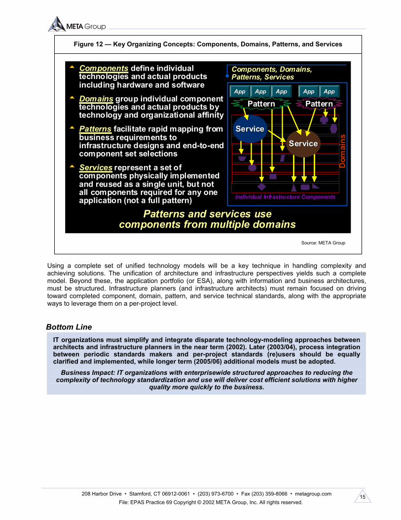
Tools for Standards Documentation and Sharing All this standards information might best be presented for use in the form of a Web site that enables access to preset component, domain, pattern, and service documentation (e.g., HTML pages, MS word documents, Excel spreadsheets, PDFs, PowerPoint files). A better approach would leverage a relational database to house the entire standards or planning portfolio (still Web accessible). This would enable structured relationships between base components and the domains, patterns, and services they are included in. Moreover, linking this to the application portfolio (via the pattern construct) is imperative. We believe a key to understanding infrastructure value is the ability to map the use of infrastructure to applications, both as currently installed as well as for future needs. Keeping such a standards asset portfolio up-to-date should be a significant work effort to be divided across architecture or infrastructure planning groups. Staffing and processes should reinforce this effort. Tools could as well, though so far our research indicates few tools exist that can provide this kind of standards portfolio off the shelf. Summary of Key Organizing Concepts: Components, Domains, Patterns, and Services To unite infrastructure planning and architecture models — taking the best of both approaches — requires aligning component, domain, pattern, and service models. Although a given organization may have other models to integrate, this example of integrating the models should show how integration could be achieved. Moreover, the resulting set of technology and standards models all have value and are more valuable for being closely related (see Figure 12 for a full mapping of models). For more information about these concepts, see the following books by Bruce Robertson and Valentin Sribar: The Adaptive Enterprise: IT Infrastructure Strategies to Manage Change and Enable Growth (Pearson Education, 2002) and Enriching the Value Chain: Infrastructure Strategies Beyond the Enterprise (Pearson Education, 2002).
Figure 11 — Service Levels (Characteristics or “Abilities”)
Source: META Group
• Conventional/operational infrastructure service-level metrics (measured, quantitative) − Scalability (throughput and response time) − Availability − Recoverability
• Extended infrastructure service-level metrics (harder-to-measure characteristics, qualitative) − Security − Integrity − Integratability − Usability − Sourceability − Supportability − Speed of initial development − Deployability − Reusability − Affordability
• Adaptive service-level metrics (any previous metric over time) − Incremental “capacity on demand” for any service level − Changing business logic − Changing presentation logic − Upgradability − Integrating new sources/consumers into the application
This list, as with other starter kits, should be adapted (and extended) as needed for design work.
208 Harbor Drive • Stamford, CT 06912-0061 • (203) 973-6700 • Fax (203) 359-8066 • metagroup.com File: EPAS Practice 69 Copyright © 2002 META Group, Inc. All rights reserved.
15
Using a complete set of unified technology models will be a key technique in handling complexity and achieving solutions. The unification of architecture and infrastructure perspectives yields such a complete model. Beyond these, the application portfolio (or ESA), along with information and business architectures, must be structured. Infrastructure planners (and infrastructure architects) must remain focused on driving toward completed component, domain, pattern, and service technical standards, along with the appropriate ways to leverage them on a per-project level.
IT organizations must simplify and integrate disparate technology-modeling approaches between architects and infrastructure planners in the near term (2002). Later (2003/04), process integration between periodic standards makers and per-project standards (re)users should be equally clarified and implemented, while longer term (2005/06) additional models must be adopted.
Business Impact: IT organizations with enterprisewide structured approaches to reducing the complexity of technology standardization and use will deliver cost efficient solutions with higher
quality more quickly to the business.
Bottom Line
Figure 12 — Key Organizing Concepts: Components, Domains, Patterns, and Services
Source: META Group
t Components define individual technologies and actual products including hardware and software
t Domains group individual component technologies and actual products by technology and organizational affinity
t Patterns facilitate rapid mapping from business requirements to infrastructure designs and end-to-end component set selections
t Services represent a set of components physically implemented and reused as a single unit, but not all components required for any one application (not a full pattern)
Patterns and services use components from multiple domains
Components, Domains, Patterns, Services
Individual Infrastructure Components
ServiceService
ServiceService
AppApp AppApp AppApp AppApp AppApp
Dom
ains
PatternPattern PatternPattern
Individual Infrastructure Components
ServiceService
ServiceService
AppApp AppApp AppAppAppApp AppApp AppApp AppApp AppAppAppApp AppApp
Dom
ains
PatternPattern PatternPattern

ME
TA
Del
ta
Copyright © 2001 META Group Inc. GLOBAL NETWORKING STRATEGIES is published by META Group Inc., 208 Harbor Drive, P.O. Box 120061, Stamford, CT 06912-0061.Phone: (203) 973-6700. Fax: (203) 359-8066. Web: metagroup.com. This publication may not be reproduced in any form or by any electronic or mechanical means, including informationstorage and retrieval systems, without prior written permission. All rights reserved. Reprints are available.
Global Networking Strategies
Date: 1 October 2001
Business Impact
File: 911Authors: Bruce Robertson and Morgan Gerhart
The Seven Infrastructure Patterns Revisited. The concept of an application pattern remains core to buildingand maintaining an adaptive infrastructure. However, evolving business requirements, changing technologies,and maturing IT skill sets will force infrastructure development organizations to continually examine and evolvepattern portfolios.
META Trend: During 2001/02, users will outsource non-strategic components while developing centers ofexcellence for strategy/architecture, infrastructure planning, and partner management/negotiation (2001-04).Through 2006, infrastructure cost metrics will be modified from net present value/return on investment to totalcost of ownership models, and shift from cost containment to value generation/agility to absorb rapidlychanging business requirements.
Through 2005/06, best-practice infrastructure development(ID) organizations will continue to decompose business-driven application requirements (i.e., Web storefront, salesforce automation, sales analysis) into the technical infrastruc-ture patterns best equipped to support these applicationrequirements (see GNS Delta 617, 10 Sep 1998). However,though the definition of what a pattern is should remainrelatively constant, the inventory of patterns that constitute anID organization’s “pattern portfolio” should not remain staticover time. Indeed, our research indicates best-practice IDorganizations will continually refine their pattern portfolio asbusiness requirements, IT skill sets, and technology compo-nents change.
META Group’s Pattern Portfolio Revisited
Indeed, just as we advise ID organizations to continuallyenhance and evolve pattern portfolios in response to change,we have also refined our portfolio of “core” infrastructurepatterns from seven “core” patterns and 12 e-patterns downto a starter kit of nine patterns (see Figure 1 in Addendum).The main driver for this reduction in patterns is the mergingof e-business infrastructure with traditional infrastructure,obviating the need for separate e-business patterns. Indeed,through 2002/03, as “e-business” and “business” becomeintrinsically intertwined for most organizations, supportingseparate e-business infrastructure will be a strategic disad-vantage for most organizations.
The Transact Patterns. The transact patterns are designedfor business use cases requiring read/write access to datarecords. However, given that transact applications can be
built numerous ways, we have defined three distinct trans-act patterns:• 1-tier transact: These are batch-processing applications
or online transaction processing (OLTP) applicationswithout logical abstraction between presentation, appli-cation, and data logic. Although the application itself isfully centralized (often on a mainframe), users may bewidely distributed, due to the wide-area network (WAN)-friendliness terminal traffic.
• 2-tier transact: This is a fat-client on the desktopcommunicating directly with a back-end database server,or a Web server that intertwines CGI/ASP/JSP presen-tation and application logic. It is the quickest and leastexpensive (from a development perspective) of the trans-act patterns. However, it has several major network andserver scalability drawbacks, making it increasingly unsuit-able outside a workgroup. Furthermore, the heavyintegration of application logic and screen presentationlogic make application-to-application integration extremelydifficult. This tight coupling also significantly complicatesextending an application to multiple points of interaction(POIs — e.g., wireless, pager, IVR).
Infrastructure development organizations mustcontinue to evolve their core pattern portfo-lios in response to changing businessrequirements, maturing technologies, andevolving IT skill sets.

ME
TA
Delta
Copyright © 2001 META Group Inc. GNS 1 Oct 01.911
Bottom Line
• 3/n-tier transact: This is a thin, presentation-logic-onlyclient (or Web or other presentation server for n-tier)communicating with a client-neutral, server-based appli-cation logic, which in turn communicates with a back-enddatabase server. It is the most scalable and flexible transactpattern. Due to the WAN-friendliness of the client toapplication server protocols (particularly HTTP), userscan be highly decentralized. When implemented correctly,the n-tier pattern results in clearly defined interfaces,making it the most flexible to integrate with other appli-cations or POIs.
The Publish Patterns. The business use case for thethree publish patterns is for read-only access to information/data(e.g., data warehousing applications, viewing files from a Webbrowser, Webcasts). Although the publish patterns may sup-port interactivity (submitting queries for processing), they do notsupport write activity (changing the state of stored data). This isthe fundamental difference between the publish patterns andthe transact patterns.• Client/server (C/S) publish: This pattern is defined by
the use of a fat client (e.g., a sophisticated businessintelligence client) and associated session-oriented proto-col (e.g., Oracle SQL*Net) between the client and back-enddatabase. This pattern is best used for implementingsophisticated data analysis capabilities to a small, well-defined user base.
• Web publish: The Web publish pattern is defined bythe use of an HTML browser interacting over HTTP, toenable read-only access to structured documents (e.g.,XML, HTML). Therefore, it is more flexible than theC/S publish pattern in supporting large, less-defineduser bases, but is limited (due to HTML/HTTP techni-cal limitations) in the sophistication of read-onlyinteractivity/analysis it can support.
• Stream publish: The business use case for the streampublish pattern is for real-time publishing of streamingcontent (e.g., audio, video, text) to “player” (e.g., WindowsMedia Player, RealAudio) clients. Although the Webpublish pattern enables downloading (HTTP as a file-transfer protocol) of multimedia content to be played,
later the latency requirements of near-real-time (i.e., broad-casting a live Webcast) are different enough that streamingrequires a separate pattern.
The Collaborate Patterns. The business use case for thecollaborate patterns is person-to-person communication,usually centered on shared documents or groups of docu-ments. Although both this and the transact patterns enableread/write access to information, the transact patterns aredesigned to handle shared read/write access to records,whereas the collaborate patterns are designed around sharedread/write access to documents.• Real-time collaborate: The infrastructure necessary to
support this pattern is similar to the infrastructuresupporting the stream publish pattern, because bothinvolve enabling real-time transmission of information(e.g., audio, video, chat, voice). However, because collab-oration involves bidirectional transmission (vs. one-waypublishing transmission), real-time collaborate warrantsits own separate pattern to account for network jitter andother infrastructure complexities.
• Store-and-forward collaborate: The use case for thispattern is “ad hoc” sharing of documents (e.g., using thestore-and-forward characteristics of e-mail to transfer“attachments” between members of a workgroup orjust storing on a shared file server). Although easy toimplement (and very widely used for collaboration), thetechnical components used to implement this pattern(i.e., SMTP, NNTP) offer little in the way of integrityenforcement/version control, forcing users of the appli-cation to keep track of these variables themselves (i.e.,the “who has the latest version of the file?” problem).
• Structured collaborate: Structured collaborate (a.k.a.“workflow” or “document management”) implementsautomated coordination of changes (version control, check-in/check-out, data validation) that the store-and-forwardcollaborate pattern lacks. For this reason, it is more scalable(from a business perspective) for business use cases requir-ing these capabilities, but it requires a longer implementationcycle and is several times more expensive because differentapplication solutions are usually required.
Methodologies enabling rapid translation between business application needs and IT infrastructurerequirements are key to overall organizational success.

ME
TA
Del
ta
Copyright © 2001 META Group Inc. GLOBAL NETWORKING STRATEGIES is published by META Group Inc., 208 Harbor Drive, P.O. Box 120061, Stamford, CT 06912-0061.Phone: (203) 973-6700. Fax: (203) 359-8066. Web: metagroup.com. This publication may not be reproduced in any form or by any electronic or mechanical means, including informationstorage and retrieval systems, without prior written permission. All rights reserved. Reprints are available.
Global Networking Strategies
Date: 1 October 2001 File: 911 Addendum
Figure 1 — Infrastructure Nine-Pattern Starter Kit
Patterns capture experience and best practices for business/application projects as designed for a particularend-to-end set of components or services.
Transact Patterns
1-Tier Transact
ServerClient
Screens and Keystrokes
1-Tier Transact
ServerClient
Screens and Keystrokes
ServerClient
Rows (SQL)
2-Tier Transact
ServerClient
Rows (SQL)
2-Tier Transact
3/N-Tier Transact
ServerClient
(SQL)Requests
Server
3/N-Tier Transact
ServerClient
(SQL)Requests
Server
Publish Patterns
Client/Server PublishRows (SQL)
Data ServerClient
Client/Server PublishRows (SQL)
Data ServerClient
Web Publish
Data ServerClientWeb
Server
Pages Files, Rows
Web Publish
Data ServerClientWeb
Server
Pages Files, Rows
Stream Publish
Client Server Data Server
Audio/Video Stream
Files
Stream Publish
Client Server Data Server
Audio/Video Stream
Files
Real-Time Collaborate
Server
Text, Audio, Video Stream
Client Client
Real-Time Collaborate
Server
Text, Audio, Video Stream
Client Client
Collaborate Patterns
Structured Collaborate
Client Client
Documents, Files
App/Data Server
Structured Collaborate
Client Client
Documents, Files
App/Data Server
Source: META Group
Store-and-Forward Collaborate
Data ServerClient
Documents, Files
Client
Store-and-Forward Collaborate
Data ServerClient
Documents, Files
Client
Logical ProcessingResource logicBusiness logicPresentation logic (generation)Presentation logic (rendering)
ExampleDBMSApp serverPresentation server (e.g., Web)Client, desktop
LANWAN
Physical device
Icon
Pattern Thumbnail Legend

ME
TA
Delta
Copyright © 2001 META Group Inc. GNS 1 Oct 01.911 Addendum

ME
TA
Del
ta
Copyright © 2001 META Group Inc. SERVER INFRASTRUCTURE STRATEGIES is published by META Group Inc., 208 Harbor Drive, P.O. Box 120061, Stamford, CT 06912-0061.Phone: (203) 973-6700. Fax: (203) 359-8066. Web: metagroup.com. This publication may not be reproduced in any form or by any electronic or mechanical means, includinginformation storage and retrieval systems, without prior written permission. All rights reserved. Reprints are available.
��������������� �����
Business Impact
Server Infrastructure Strategies
�������������� ������������������
�������� �� ��� ���� � �� ������� ��� � � ���� ������� � �� ��� �������!� ������ ���� ����� "#� ��$ ��� ���� �
��%��������&"�'����(���������������������������� �(�� �������������� ��������������� � ���� ���)����"�
�$$� ������� �*�� ���� ��������������%�����$ �����������$ ��� ���� ��������������������� ��������������� ����
��������%���� %������ �������� �)
META Trend: Infrastructure development (ID) will be one of the key strategic IT disciplines through 2003/04+,
complementing application delivery and enterprise operations. By 2003/04, to enable adaptive, robust, and
affordable infrastructure, the ID organization’s role will evolve from infrastructure planning to delivery of
universal services (execution, security, and directory) and integration services (application, analytic, portal,
and content). Application developers will consume these shared services and interfaces to concentrate on
business logic and presentation issues.
+�������� ����������� ���� �� ��������� ��%�� ���� ����
� �,���� ���� ���������� ���������������!������,�����
�������� �������,�������,�������������� ��� �-������� �)
.������������������������������ ����������� ��������
�(�� �� ��%���� ��!���� � ���������� ����������� /���%�0
��1�� �/����1��������������,� ������ ��������� ����
�����������������0��������%����������������� ��*
�����%�*� "#� ��$ ��� ���� �)� +���0 ������� � ���� ������
� �� ������������������������������!�����������������������
��$ ��� ���� �� �������� ���� ��%�������� ��� ������
������������$�������������%��������&��'������� 0
������� � ���)� +!� ����-��*� �������� � ���� ������� ,���
��%����������������$ ��� ���� ����%��������&"�'���� �0
������ ���������� ��� �������� ���� ��%������� ��� ��*
�����%�*�"#���$ ��� ���� �)
+!�����-��*�����0 �������� ���� �������,������%��,���
��!����������"������%������&����������$�������������������
��$ ��� ���� �����������'����� ����������,����������
�(�� ������� %��� ��$ ��� ���� ������ ����������)�#��!
,������%�������� �����%��!���%���������� ����� %��������
���� $��������� ����������%���� %������ �������� ���&���'
��������� ���� ������� ��� ��������� ��������� �(�� �0
�����)� +!� ���2-�3*� ���� ��4� ��!� �$� ����0 ������
� ���� �������,������%����������������� �������)
5 ���� ��������������%���,�$��!������������������!
����-��� ,���� �����%�� ��������%�� ��%������� �%� � ����
��������������� �������� �����,� ���������������
����� �������)�+������� ������4� ��!��$�� ���� ������
,�������������������� ����������$� ������*������$�����
�� �������������������������%����%�������,�������� �
�����*��� %����0��������$ ��� ���� ��,��������%����������������
�� ��������2-�3)
����� ��� ��� ���� ��� �������"�������� �!���������$
"�*�����$���������� ����!������������������%�����*���������
• ��$��������$ ��� ���� �
• 6��������������$ ��� ���� ����������������%���0
����� �������
• 7������������$ ��� ���� ��������������������!������� ���
• 7�������������� ��&� ���$����'� �������,������������ ���
• ����! ���������� ���������������� ��
• .������������ ���,���������� ����$ ��� ���� �����������
5� � ���� ������,������������������������0 �������"�
������ ��� ��� ����*� ���������� ���� �� ��������� ��
������ �� ��$ ��� ���� �� ���������*� ������� �����0
�� !*��������$$�������������������8���������$�����$���
�����%�� ��$ ��� ���� �)� ����������� �� ��� �(�� ���
��$ ��� ���� ���� %����)
Businesses will gain competitive
advantage by adopting best practices for
creating services that support business
application development agility.

ME
TA
Delta
Copyright © 2001 META Group Inc.
Bottom Line
SIS 12 Sep 01.933
"��������������� ��������*����� %�����8�����,�������� %���
������� ����������� ���� �����������!� $� �� $� ������
���������������� %���� �%��� )��������� %���� �%���
���������!�� ����� ��!��������������� $� ������ %���)
"�$ ��� ���� ���� %����*����� ������ *��$$� ��������$���0
��������!���������������������������������!���� �������
����� �$� ��$ ��� ���� �� ���������� ���� ����� %����)� �
�� %������������%������$� ������'�����������������������0
������� $ ��� ���� �� %���� ���� $���*���9���� ����������� ��
�������������������������,��������$$��������� %������� �
&���� ����������� �%���� %������%����� ���� ����������':
�����'�������� ������,����������� %�������������!��� ������
�������������)
�������� �� �� ��� ���� � �� ������� "�� �$$���*� ���
���,� 9��$$� ����� �������$������$ ��� ���� ���� %���)�"�
��� ���� �� ������ ��$ ��� ���� �� ��������*� ���� �� �0
�����������!������$���$ ��� ���� ������������&������*
���� �*��,������*���$�,� �*����)'*����������������%�����
�����������!��$���!�� ������ �������������������*�����
&%�����������������$� ���� $����'� �%������������$� ������
�� %������������ �����������������������)�.� ������ 0
���!*���,�%� *������$ ��� ���� ���� %������������ ��������
�$$� ���!���������!������,�������������!�����������������
����������)�; ������������� %�������!������������������
�� %����*�� ����*������������!���%������� �)� "������!*
� ��������*���������������� ���8�������$����� ��!��� %����)
"���� ������ �� %����� �������� � �����������*� �������*� ���
����!���� ����� �����)� �� ���0� ��� ���,� 9�*� �� ���� ���*
���������������������� ���� ��������� ������ %�����&���
���� ���������������')
�� ��� ���� ��� ���������������� ����������5�%�0
����!*�����$�����������!��!��� �%������!���$ ��� ���� �
�� %������ ��������,)�����������,��������9�������������
� ���� ���������$�����������!��8������!������������������0
��������������9�����,���������������8���$���$ ��� ���� �
��%�������������,�����&�������� ���������������')�#���
�(�� �����9�����8���������������$�,������ %����������%���*
��� �*�������������,����������� ���� �����<����$ ��� ��0
�� ��� �$����)�"�������$� �����8����������!�����$�������������
%����� ���� �����%�� �� ������ �$� ��������� ��$ ��� ���� �
��%���������������� ��!������ �����$��������=5"�$ ��
��$ ��� ���� ����%��������)�#��������������� �����������
��� ������������ �%������������8��$� ����(�����!�4����$!0
������$ ��� ���� ���������)
������������ ��� ���� ��� ������������ ������
�����������$ ��� ���� ���� %���������������� �����,� ��
�$������� %������ ���������������*���� ������%� �������
������ �������8���)�#���������� !�$ ���,� 9�$� ���%������
���� �%��������$ ��� ���� ���� %��������� ���� ���!������� ���
����� �(�� ���$� ������� %�����&�)�)*����� �����-�����%� !
����������')�.� ����� ����*���$ ��� ���� ���� %��������
���� �� �����!� ,���� �$���� ��� ��%������ ������� �� %����
&��� ������ ��8� ����')�6�� ����������� %�������������0
��������������� ���,���� �%������� �������,��� ��������
$� ���%���������$ ��� ���� ���� %����)
�� ��� ���� ��� ���������������� ��� ��!"#�� �����
6%������������ ������ ���� ���� ������������%������ ���
�����������/��������������%� �1���$ ��� ���� ���� %����*
��� ������,���� �������� ��� ������!��������� ����������
/�,���1��!���%� ���� ����$������ ���� �����)�7������
�������4������������������������ ����� ���� �������
������ ���*�$� ��8����*���!������ �������������������
��� �����$ ��� ���� ���� %�������������������������/��0
�������1������� ������ �������������%��������� ��)
>�,�%� *� ������ ��� ������� ��!� ������� ���$����� ����
���� ��-�,�� ����$ ���������"�)�"��$ �������������
��%���� ������������ �������������������������� �(�� ��
��� ��� �� ��������� ����� ���������� �(�� ������� ���
����������������$� �������������%���� �����������0
�� ����,����/��������������1�"�� �(�� ������)����������
��%���� ����!�������������� ��������%������,�������!
� ���%�� ��� ��� ����� �$� /���� 1� �� $� ��� ��$ ��� ���� �
��%���� �*� ����� ������� /��������1� ������� ���������� ��
������ ,���)� ?�%� �������*� ���� �%� ���� ��������� ����$���
,��������%��!����$�%� ��$���%����$������������ ����� ���
���������������$ �������%���������� ���������������
��$ ��� ���� ������������)
Achieving infrastructure development maturity requires proactive development of infrastructure
services to support accelerated application development and integration.
ME
TA
Del
ta
Copyright © 2001 META Group Inc. SERVER INFRASTRUCTURE STRATEGIES is published by META Group Inc., 208 Harbor Drive, P.O. Box 120061, Stamford, CT 06912-0061.Phone: (203) 973-6700. Fax: (203) 359-8066. Web: metagroup.com. This publication may not be reproduced in any form or by any electronic or mechanical means, includinginformation storage and retrieval systems, without prior written permission. All rights reserved. Reprints are available.
��������������� �����
Server Infrastructure Strategies
������������������
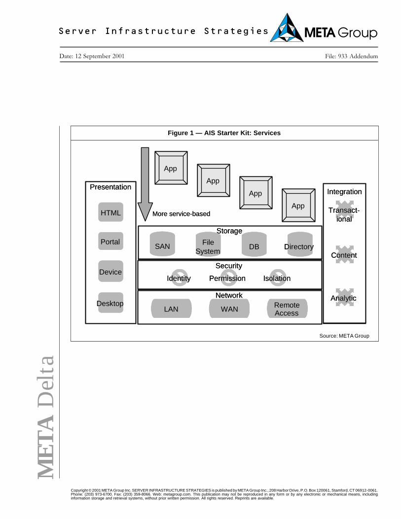
Figure 1 — AIS Starter Kit: Services
Source: META Group
Storage
SAN FileSystem
DB Directory
Integration
Content
Analytic
Transact-ional
Security
Identity Permission Isolation
App
App
App
AppMore service-based
Network
LAN WAN RemoteAccess
Presentation
HTML
Portal
Device
Desktop
Storage
SAN FileSystem
DB Directory
Integration
Content
Analytic
Transact-ional
Security
Identity Permission Isolation
App
App
App
AppMore service-based
Network
LAN WAN RemoteAccess
Presentation
HTML
Portal
Device
Desktop

ME
TA
Delta
Copyright © 2001 META Group Inc. SIS 12 Sep 01.933 Addendum
Individual Components
App App App App
Pattern Pattern
API
Service
Service
App
Individual Components
App App App App
Pattern Pattern
API
Service
Service
App
Figure 2 — Organizing and Building Infrastructure
Source: META Group