september vol. dc - r.l. mccoyrlmccoy.net/portals/1/pdf articles/concrete international...
TRANSCRIPT
- SEPTEMBER 2005 Vol. 27 NO. 9
DC
•
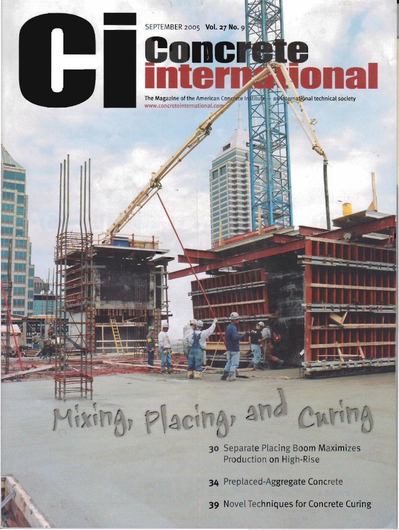
30 Separate Placing Boom Maxim izes Production on High-Rise
34 Preplaced·Aggregate Concrete
39 Novel Techniques for Concrete Curing

5e arate Placing oom aximizes Prod ct-o on
High-Rise Detac hable boom sup ported by self-cl imb ing formi ng system
BY GARY BROWN , NEAL BURNED, AND TOM ARNOLD
SEPTE BER 2005 1 Coner.." irltalrll

Separate placing booms are often used for placing floors on high-rise build ings. With a reach of 100 it
(30 m) or more, they can cover areas great er than 30.000ff (2800 m") and deposit concrete pr ecisely where it's needed. Mounting a detachable boom on a mast projecting from th e floor below. however, has some disadvantages . The tubular towers often used for a mast require a 3-rt ( l-m) diameter hole in each floor that must later be filled with concrete. Lifting the boom and mast to eac h new elevation also requires costly crane time. For the 23-story Conr ad Indianapolis Hotel and Residences complex in Indianapolis , IN. thes e disadvantages wer e avoided by attaching th e boom to self-climbing forms that transmitted the placing-boom loads to the core-forming supports .
FOUNDATION CHAllENGES Figure I shows a construction photo of the cast-In-place
concrete structure. The completed bulldtng co mprises one level below grade. street-level retail space, and 243 upper level luxury hotel roo ms topped by 18 residential condo miniums. The concrete frame is bound by s treets on two sides and by two existing build ings . The offset dimens ions to the two adjacent build ings are tightabout 6 in. (150 mm) and 3 in. (75 mm). In addition, one corner of the frame cantilevers over a portion of an adjacent building.
A two-level. below-grade parking garage for one of the adjacen t buildings was-directly beneath part of the new st ructu re. This presented the first challenge of supporting the garage, as foundations and IO.OOo-psi (69-MPa) con crete columns had to be installed through it . The existing park ing garage beams had to be shored while sections of concrete beams were removed, keeping the reinforcing stee l inta ct. Then. new vert ical reinforcing bars with sizes up to No. 14 bar were fished through th e exposed beam reinforc ing (Fig. 2) .
As installatio n of these foundatio ns progressed . the main excavation for the basement was also commencing adjacent to the underground parking facility. This part of the foundation was a combination of drilled so ldier beams and lagging on th e so uth end of the s ite, augercast tangent wall to support the adjacent Indianapol is Arts Garden , and drilled tie backs through the Ioundation wall for th e old Roosevelt Building that had previously occupied the s ite. During the excavation. a preliminary tes t dig at the exis ting Arts Garde n foundation was needed to determine whether or not the loundation res ted on piles as was indicated by the original design of that building. The test dig revealed that there were no piles p resent and that a conventional spread footing had been install ed . This requi red a redesign of the auger-cast tangent wall to hold the spread footin g at street level while a 26-1t (8-m) deep excavation expose d one side 01 the installed tan gent wall (Fig. 3) .
Fig. 1: Two elevator shaft cores that were constructed using a self-climbing forming system. The placing boom was mounted on the core in the background because it passed through the full height of the building. It was more efficient to place all of the concrete from one boom position rather than moving the boom from one core to the oth er. Photo courtesy of Boker Cuncrete Construction
Fig. 2: The ro .ooo-psl (69-MPa) concrete columns for the structure also had to be tied into reinforced concrete beams for an existing parking garage directly beneath part of the new structure. (a) Shoring on each side of the columns allowed workers to remove sections of the beams while the reinforcing steel remained intact. Then, new vertical reinforcing bars with sizes up to No. 14 were fished through the exposed beam reinforcement; and (b) the columns were cast. Photos courtesy of Fin k Roberts & Petr ie
Fig. 3: During the excavation, a prelim inary test dig at t he existing Indianapolis Arts Garden foundation revealed that the piles indicated in the original design were not present and that a conventional spread footing had been installed. This requir ed redesign of the auger-cast tangent wall shown to hold the spread footing at st reet level while a 26-ft (8-m) deep excavation was performed on one side. Phma courtesy of Bak er Concrete Construction
Concrete Internad nal / SEPTEMBER2005 31

Fig. 4: Foundations for th e previous building on the site were underlain by foundations for an even older building. Instead of removing both foundations and creating a deep layer of disturbed material: (a) soil between the foundations was excavated down to suitable bearing soil; and (b) the existing foundations were encased in 2500-psi (17-MPa) concrete. Photos col1l1esy of Baker Concrete Construction
During excavation of the basement area, found ations for the Roosevelt Building were also to be rem oved. It was found . however . that these foundations had been built on deep er foundations from an even earlier building. Removin g both foundations would have increased cost and creat ed a deep layer of dis turbed mat erial. The owner's construction director and the struc tural en gineer so lved this problem by having the concrete co ntracto r excavate between the foundations down to suitable bearing so il and then encase the existing foundations in 2500-psi (17-MPa) concrete (Fig. 4). The foundations for the new building wer e then placed and backfilled.
PLACING BOOM SOLVES PROBLEM Levels I, 2, 5, and 6 are wide module [oist sys tems,
32 SEPTEMBER2005 / Concrete lot6r08U0081
Fig. 5: The cross frame for the placing boom consisted of 16-ln. (4oo-mm) wide-flange beams that bolted to the formwork. Once the boom was pinned to the mounting frame, it remained in place through completion of the job. Photo courtesy of COl}' Brown
while Levels 3 and 4 are post -tensioned beam and slab parking decks, and Levels 7 and above are post-tensioned flat plates. Formwork for the joist system and parking decks was supported by conventional shoring. while flying-for m truss tables su pported Iorrnwork for Levels 7 and above.
The limited space on the job-s ite allowed use of only one tower cr ane that als o had to cycle the flying forms. That made crane time scarce. Because it could also carry a placing boom. a self-climbing sys tem used to form the two elevator-sha ft cores was part of the so lution to this pr oblem . Placements for the first s ix floors were all completed with a 170-ft (52-m) tru ck-mounted boo m pump, but placements for the rema ining floors were made with th e de tachable boom from a Schwing lOS-it (32-m) 2023-5 tr uck-mounted co ncr ete pump.
The boom was mou nted on a cross frame attached directly to the top of the forming system for one of the cores . If th ere had been only one core located at the center of th e building, all of the deck area could have bee n reached by the boom. With two cores, and the boom mounted on only one of them, ext ra line was needed to reach some of the deck. but this was more efficient than moving the boom fro m one co re to the other. The larger core termin ated at the condominium level, so the boom was mo unted on the smaller cor e that passed th rough the full height of the build ing.
The cross frame for the placing boom consisted of 16-in. (400-mm) wide-flange beams th at were bolte d to the for mwork (Fig. 5) . Once the boom was pinned to the mount ing frame, it remained in place through comp letion of the job. High-capacity hydraulic jacks lifted both the interior and exterior shaft forms along with th e boom. In designing the forms, dynamic loads imposed during pumping had to be considered .
ROUTING THEPUMPLINE After completion of ea ch deck. ca rpenters jacked the
forms and boom into position for the next plac ement wh ile the pumping crew added add itional pump line to reac h the boom's new location. Insta lling the pu mpline inside the elevator shaft wou ld have permitted the crew to add line sections while working from scaffold ing suspended below the form. Whe n th e job was comp leted . however, removing the line would ha v been more difficu lt and dangerous with mos t of the eleva tor shaft be ing open, and no scaffolding present.
To ma ke teardown easier. the pipeline was rou ted through a ventilat ion ch ase adjacent to the elevato r core. Crews safe ly removed the line late r while working fro m each floor . thus elimi nat ing the need for scaffold ing.
PUMPING THE CONCRETE SAFELY The cons truction schedule called for completing on e
de ck per week, with two placements required for each deck. Placements on th e flying forms started in January , so rap id early strength development of t he concrete dur ing cold weather was crucia l to meeting the schedule.
",The 5800-psi (4Q-MPa) deck concrete set so ra pidly that floating and tr oweling opera tions were being ca rried out within 20 It (6 m) of the pump dis cha rge. The fast-se tting properties of th e con crete ra pidly increased pump pressure as the bui lding height and line length increased .
The 105-ft (32-m) t ruck-moun te d concrete pu mp kit pe rmits pis ton s ide pumping to co nvert the pump from a low-p ressu re. high -volume machine to a high-pressure , low vo lume mac hine. At the 15th floor , with 250 It (76 m) of line. the pump operator switched to th e p is ton s ide of the pump to inc rease pressure on the co ncr ete and reduce s tress on the pu mp wh ile s t ill kee ping the output at the des ired level.
When pumping on the rod side of the pis ton, less area is available to push the concrete through the line an d less forc e can be applied to the concre te. SWitching to t he pis ton side ra ise s t he force an d the maximum pressure on th e concr ete, so the entire delivery system must be rated to handle the higher pr essure and also must be mainta ined in like-ne w co nditio n. It's even more importa nt than usual for th e pumping cr ew to observe safety rules for: • Opening lines under pressure; • Sucking back plugge d lines be fore ope ning; • Checking the p ressure-handling capac ity of pip es.
hoses . and clamps in the delivery sys tem ; an d • Avoiding th e dangers of line blockages .
The pump. operator. and crew hand led this construction ch allenge, and the building was topped out in June 2005. Occupancy is expected by March 2006.
Selected lor rea der Interest by the edit ors
PROJECT CREDITS Own er/Developer: Circle Block Partners. LLC.
Indianapolis , IN
Civil and Structural Engineer: Fink Roberts & Petrie. Inc.. Indianapolis . IN
Construction Manager: Hunt Construction Group. Inc.. Midwest Divis ion. Indianapolis. IN
Concrete Contra ctor: Baker Concrete Cons tru ct ion. Monroe, OH
Pum ping Contractor: R.L. McCoy , Inc.. Columbia City. IN
Gary Brown is Manager of the Indianapoli s, IN. office for R.L.
McCoy, lnc., an Indiana-based concrete pumping contractor. He
has been in the concrete pumpin g business for 27 years as an
operator and manage r.
Neal Burnett is Operations Manager for Baker
Concrete Construction in Indianapolis, IN, and
has worked in the commercial construction
business for 24 years.
Tom Arnold is Superintendent for Baker
Concrete Construction in Ind ianapolis, IN.
and has been in the commerc ial construction
business for 25 years.
Advertise in Concrete International
For details. contact Jeff Rhodes Phone (410) 584-848 7 · e-mail: [email protected]
Conere' me adonaI / SEPTEMBER 2 0 05 33