septic stack system - virginia department of health septic stack system uses four-inch diameter...
TRANSCRIPT

Septic Stack System Installation Manual—Virginia
THE MOST ADVANCED NAME IN WATER MANAGEMENT SOLUTIONS™

2
ADS, Inc. • 4640 Trueman Blvd. Hilliard, OH 43026 • 800-821-6710 • www.ads-pipe.com
I. Introduction 2
II. System Specification 3
III. Design Criteria 3
IV. Installation 4
Contents
The purpose of an onsite septic system is to collect and treat the wastewater from a home or establishment and then disperse the effluent (water) into the soil, which further treats and cleans it to a standard that minimizes or eliminates contaminates. The septic tank or primary treatment device separates the solids and sends the effluent to the drainfield. The purpose of the drainfield is to store and disperse the effluent from the primary treatment unit into the soil.
Early drainfields used stone gravel to create a void space. Then clay tiles were added to increase storage capacity. Centuries later the tiles were replaced with clay pipes and eventually to black, high density polyethelene (HDPE) corrugated pipe.
Within the last few decades, as our lifestyles have changed, it has become necessary to improve upon the efficiency and function of these stone systems. Drainfield requirements have become larger while available areas have become smaller.
The ADS Septic Stack systems were developed to offer a common sense approach to this need, while offering substantial advantages over stone drainfields.
The Septic Stack system uses four-inch diameter corrugated polyethylene perforated pipes to create void space for storage, in lieu of stone. The capacity, distribution and the simplicity of installation are beneficial to the contractor and the end user. There are three Septic Stack systems for consideration: 9-pipe incorporates eight void pipes and one distribution pipe; 11-pipe uses ten void pipes and one distribution pipe; 13-pipe uses twelve void pipes and one distribution pipe. With the exception of packaging and square footage ratios, these systems are functionally equivalent when used for their intended purpose.
The ADS distribution pipe disperses the effluent into and around the voids created by the specially-banded ADS void pipes. These void pipes were carefully designed with both holes and slots, allowing them to both collect and disperse the water as it passes over the thousands of corrugations in the pipe. They are strapped together to give the system strength.
I. INTRODUCTION

3
ADS Septic Stack-9Septic Leachfield System
All ADS Septic Stack systems are currently composed of a distribution pipe (also called a "D-pipe") and bundled and strapped void pipes. A label is attached to the top of the bell of each ten-foot stick of each product.
The 9-pipe system consists of 8 void pipes and a distribution pipe. The void pipes are bundled in 5 and 3. The distribution pipe is included within and the entire unit is strapped together to make one exceptionally strong part. The distribution pipe includes a snap type bell end that extends past the void pipes in order to make connection to other sections.
The 11-pipe system consists of two bundles of 5 void pipes and a single distribution pipe field-installed between the void pipe bundles.
The 13-pipe system consists of two bundles of 5 void pipes and a bundle of 2 void pipes and a distribution pipe that is field-installed in between the two 5-pipe bundles. The distribution pipe is placed in the upper portion of the three.
II. SYSTEM SPECIFICATION
Each of the Septic Stack systems is approved for use according to specific State guidelines. Application and credit for their use is at least equal to that of a conventional system. Many states will allow for a reduction in drainfield sizing.
Height of the 9-pipe, 11-pipe, and 13-pipe systems is 8.6"; with the invert of the top row pipe at 4.3". This compares to 12" of stone and an invert of 6". This 28% saving in height allows for either greater water table separation or shallower installations.
Width of the 9-pipe, 11-pipe, and 13-pipe systems are different: the 9-pipe system is 23.5", while the 11-pipe system is 28.5". The 13-pipe system is 33.5".
Based on total storage volume of void and distribution pipes the 9-pipe will hold 8.9 gallons. The 11-pipe will hold 10.9 gallons and the 13-pipe will hold 12.8 gallons. This can be crucial during periods of high demand or saturated soils due to heavy rains.
III. DESIGN CRITERIAThe ADS Septic Stack systems are designed to be installed in trench or bed configurations, in subsurface, filled, mounded, gravity fed, pumped and pressure dosed systems.
System sizing is accomplished by first having a site evaluation performed by a qualified professional Engineer, soil specialist, or local Health Department. After a permit has been issued, and the plot plan shows the intended drainfield, a simple ratio calculation can be done. Use the recommended square footage as the basis for length, width, and the total number of trenches. A level or relatively flat system installation is preferred. The installation of all distribution lines (non-header) on sloping lots should be perpendicular to the grade. Some states or codes require that the distal ends of the distribution pipes be connected to form a continuous loop. Check local codes for specific guidance.

4
IV. INSTALLATIONThe ADS Septic Stack systems are to be installed according to the prevailing codes, but within the limitations of height and width inherent in their design. The preferable application is in trenches, but when properly designed and executed, beds are both acceptable and common practice.
The soil is excavated or filled according to code with the invert approximately 4-¼" from the soil interface.
The ground is leveled or sloped according to code and the pipes are laid in.
The distribution pipe is the only pipe connected to a distribution box or header manifold as in a conventional system.
The Septic Stack systems can be laid in any configuration recognized in a conventional system. The void pipes should be viewed as the aggregate.
The 9-pipe, 11-pipe, and 13-pipe systems may be connected to the septic tank by means of a distribution box or header manifold, such as 4" ADS 3000 TripleWall, 4" PVC SDR 35, and 4" PVC Sewer and Drain fittings, or PVC lateral pipes designed for a pressure dosed system. Check local codes for connection regulations.
The use of an ADS end cap for the distal ends of the distribution pipe is acceptable in subsurface installations in trenches under most State codes.
HEADERSA header line must be supported by soil and then connected to the distribution pipe of each drain line.
The Septic Stack systems have a lot of flexibility and can be shaped. However, where gaps of more than a few inches occur as a result of bending the pipes, short sections or pieces of pipe should be inserted to stabilize the system and provide continuity.
LOW PRESSURE DOSING SYSTEMSA 2” pressure dosing pipe should be snaked down the 4” distribution pipe for the entire length of the trench. When a low pressure dosing system is required, a snap end cap shall be installed on the inlet and distal ends of the distribution pipes with a hole drilled at the bottom to accept the PVC lateral pipe. Select a hole saw the size of the outside diameter of the specified PVC pipe. The PVC lateral will enter the inlet end and exit the distal end, with the nozzles of the lateral pipe facing in the 12 o'clock position. Be sure to include a clean-out on the distal ends of the PVC laterals.
ADS SEPTIC FILTER FABRICThe open ends of the 4" void pipes must be first covered with any approved filter fabric. ADS Septic Filter Fabric is resistant to a wide variety of soil and pH conditions and is recommended where the open ends are directly exposed to the soil. This is done by placing the septic filter fabric just under the end of the bottom pipes and then covering it with two layers of cloth. The finished system must then be completely covered with a single layer of filter fabric in such a way that both the top and sides are protected from soil intrusion. It should be placed over the sides in such a way that it drapes down, covering at least the top layer of pipes. The Septic Filter Fabric should not be tucked under the bottom row of pipes, so that the water can escape should the filter cloth become clogged over time.

5
DEFINITIONS AND DESCRIPTIONSD- PipeA perforated effluent distribution pipe whose nominal inside diameter is equal to four inches. It includes a snap-fit bell that extends past the V-Pipes for connection, end-to-end, with other Septic Stack units, i.e. the void pipes are 10 feet and the D-Pipe is 10 feet, 2 inches (approx.).
This pipe is marked with a top-centered reference line (a green stripe) that is to be oriented upward. Pipe will have two or three rows of holes along bottom (dependent on state and local codes).
V- PipeA pipe that contains a minimum open area, via perforations or slots. The perforation type, placement and frequency are designed to achieve the desired open area while maintaining a minimum of 40% of the original pipe's strength.
Header PipeA header pipe is a conduit used to distribute effluent from the primary treatment receptacle's (septic tank, pump tank or ATU) outlet device to the receiving D-pipes within the absorption trenches or bed. The header pipe is used in lieu of a distribution box. A header pipe is generally easier to configure, level and adjust for the even distribution of effluent to all receiving lines in a gravity or pressure-dosed system.
D-BoxA distribution box is a device normally constructed of a durable material whose purpose is to distribute effluent received from the primary treatment receptacle's (septic tank or ATU) outlet device. The effluent flows through a solid (non-perforated) connecting pipe to the inlet side of the distribution box. The effluent is then distributed evenly to all connected field lines.
Septic StackThe name for the 9-, 11- and 13-pipe stone replacement systems.
Septic Filter FabricThe synthetic cloth material used to prevent soil migration into the pipes or rock.
CONNECTIVE DEVICESThe Septic Stack systems are designed to be used with all approved connective devices, whether they are a header pipe, low pressure dosing pipe, distribution box or a single line from an aerobic tank. Distribution boxes and a full line of pipe line fittings are available from ADS.
BACKFILLComplete the backfill of the Septic Stack system with native soil or select fill to a minimum 6 inches above pipe unless otherwise specified in the system design and as required by the permit. Backfill material must be clean and free of rocks and debris, as they may eventually impinge on the system. As common practice, avoid driving any equipment over the system prior to final backfill. Install only in non-traffic areas with a minimum of 12 inches of cover (although after consolidation, the Septic Stack meets AASHTO H-10 requirements).
These instructions should be used for general information. The permitting authority and State laws, codes and rules determine specific sizing criteria and system suitability. Please consult your State or local Health Department before considering these systems.
6
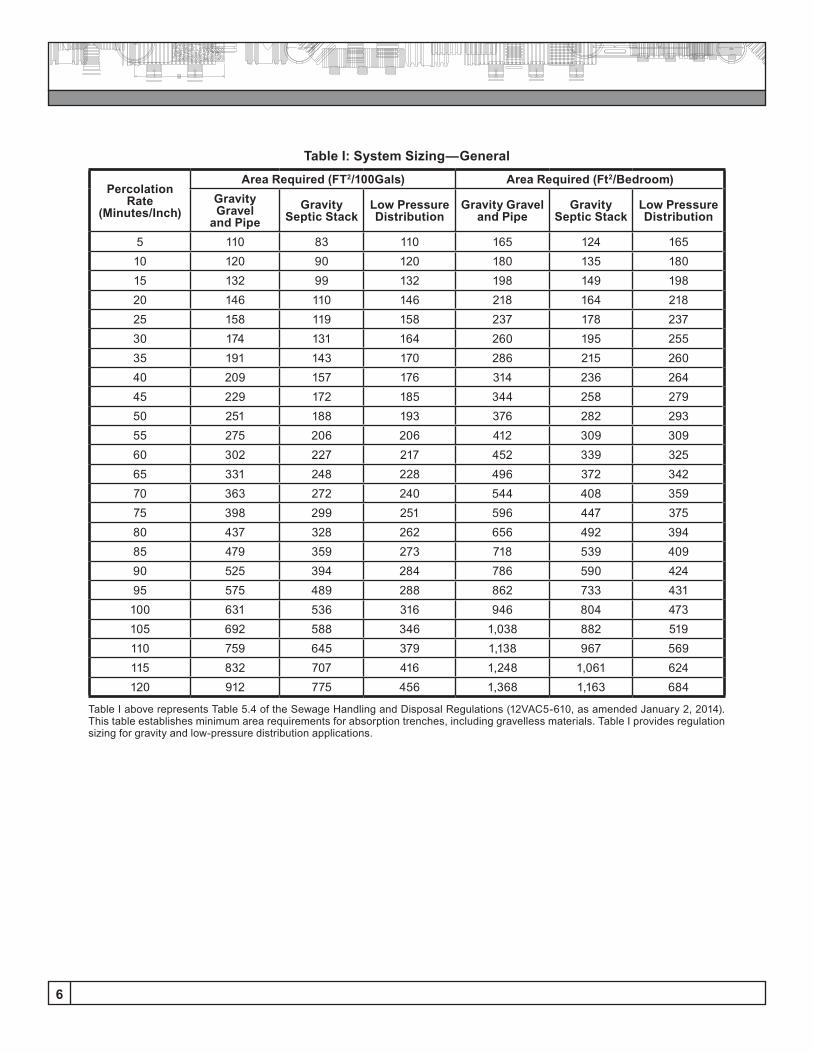
Table I: System Sizing—General
Percolation Rate
(Minutes/Inch)
Area Required (FT2/100Gals) Area Required (Ft2/Bedroom)Gravity Gravel
and PipeGravity
Septic StackLow Pressure Distribution
Gravity Gravel and Pipe
Gravity Septic Stack
Low Pressure Distribution
5 110 83 110 165 124 16510 120 90 120 180 135 18015 132 99 132 198 149 19820 146 110 146 218 164 21825 158 119 158 237 178 23730 174 131 164 260 195 25535 191 143 170 286 215 26040 209 157 176 314 236 26445 229 172 185 344 258 27950 251 188 193 376 282 29355 275 206 206 412 309 30960 302 227 217 452 339 32565 331 248 228 496 372 34270 363 272 240 544 408 35975 398 299 251 596 447 37580 437 328 262 656 492 39485 479 359 273 718 539 40990 525 394 284 786 590 42495 575 489 288 862 733 431100 631 536 316 946 804 473105 692 588 346 1,038 882 519110 759 645 379 1,138 967 569115 832 707 416 1,248 1,061 624120 912 775 456 1,368 1,163 684
Table I above represents Table 5.4 of the Sewage Handling and Disposal Regulations (12VAC5-610, as amended January 2, 2014). This table establishes minimum area requirements for absorption trenches, including gravelless materials. Table I provides regulation sizing for gravity and low-pressure distribution applications.
7
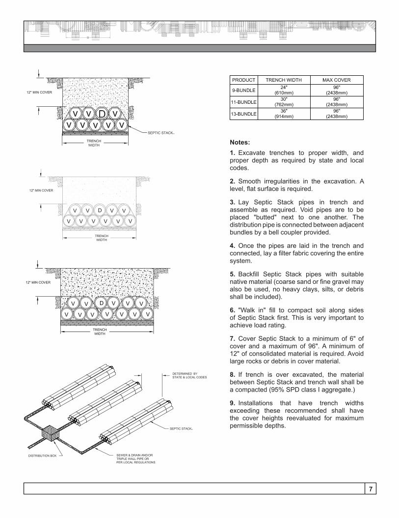
Notes:1. Excavate trenches to proper width, and proper depth as required by state and local codes.
2. Smooth irregularities in the excavation. A level, flat surface is required.
3. Lay Septic Stack pipes in trench and assemble as required. Void pipes are to be placed "butted" next to one another. The distribution pipe is connected between adjacent bundles by a bell coupler provided.
4. Once the pipes are laid in the trench and connected, lay a filter fabric covering the entire system.
5. Backfill Septic Stack pipes with suitable native material (coarse sand or fine gravel may also be used, no heavy clays, silts, or debris shall be included).
6. "Walk in" fill to compact soil along sides of Septic Stack first. This is very important to achieve load rating.
7. Cover Septic Stack to a minimum of 6" of cover and a maximum of 96". A minimum of 12" of consolidated material is required. Avoid large rocks or debris in cover material.
8. If trench is over excavated, the material between Septic Stack and trench wall shall be a compacted (95% SPD class I aggregate.)
9. Installations that have trench widths exceeding these recommended shall have the cover heights reevaluated for maximum permissible depths.

Advanced Drainage Systems, Inc.4640 Trueman Blvd. Hilliard, OH 43026
1-800-821-6710
www.ads-pipe.com
ADS “Terms and Conditions of Sale” are available on the ADS website, www.ads-pipe.comThe ADS logo, the Green Stripe, N-12®, ADS 3000® TripleWall and Septic StackTM are registered
trademarks of Advanced Drainage Systems, Inc. (AD660714) © 2016 Advanced Drainage Systems, Inc.
#11014 05/16