sequential logic circuits. 2 outline sequential circuit models –asynchronous –synchronous...
TRANSCRIPT
Sequential logic circuits
2
Outline
• Sequential Circuit Models– Asynchronous– Synchronous
• Latches
• Flip-Flops
3
Sequential logic circuits
• The main characteristic of combinational logic circuits is that their output values depend on their present input values.
• Sequential logic circuits differ from combinational logic circuits because they contain memory elements so that their output values depend on both present and past input values
4
Sequential logic circuits
Sequential circuits can be Asynchronous or synchronous.Asynchronous sequential circuits change their
states and output values whenever a change in input values occurs.
Synchronous sequential circuits change their states and output values at fixed points of time, i.e. clock signals.
5
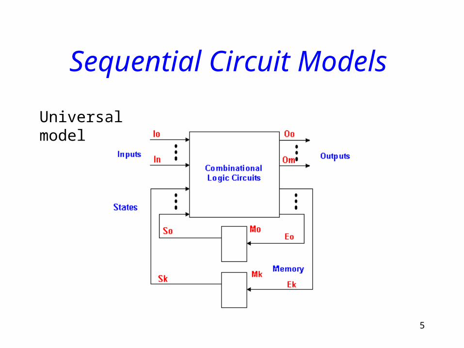
Sequential Circuit Models
Universal model
6
Memory Devices
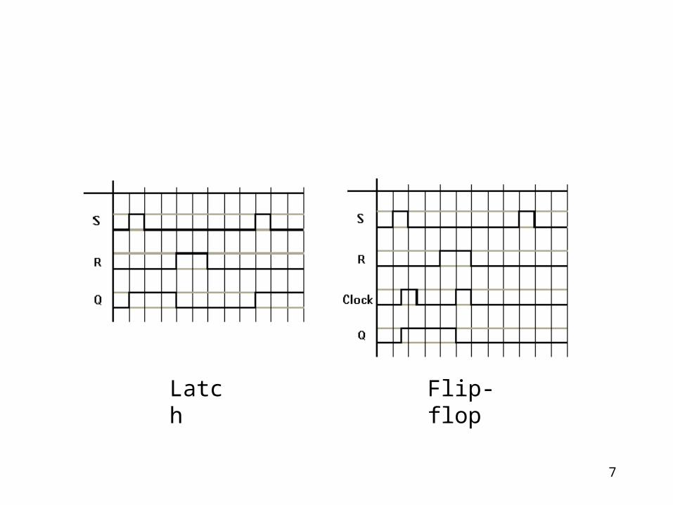
Latches A latch is a memory element whose excitation signals control the state of the device. A latch has two stages set and reset. Set stage sets the output to 1. Reset stage set the output to 0.
Flip-flops A flip-flop is a memory device that has clock signals control the state of the device.
7
Latch Flip-flop
8
Latches
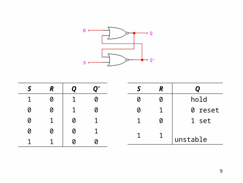
RS LatchThe RS latch is the basic memory element
consists of two cross-coupled NOR gates. It has two input signals, S set signal and R reset signal. It also has two outputs Q and Q'; and two states, a set state when Q = 1 and a reset state when Q = 0 (Q' = 1)
9
S R Q Q'
1 0 1 0
0 0 1 0
0 1 0 1
0 0 0 1
1 1 0 0
S R Q
0 0 hold
0 1 0 reset
1 0 1 set
1 1 unstable
10
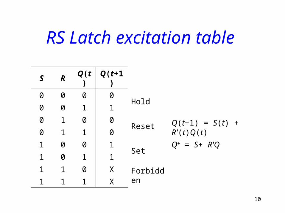
RS Latch excitation table
S R Q(t) Q(t+1)
0 0 0 0Hold
0 0 1 1
0 1 0 0Reset
Q(t+1) = S(t) + R'(t)Q(t) 0 1 1 0
1 0 0 1Set
Q+ = S+ R'Q
1 0 1 1
1 1 0 XForbidden
1 1 1 X
11
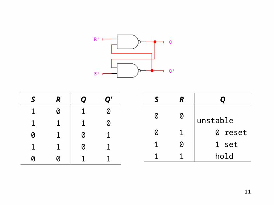
S R Q Q'
1 0 1 0
1 1 1 0
0 1 0 1
1 1 0 1
0 0 1 1
S R Q
0 0 unstable
0 1 0 reset
1 0 1 set
1 1 hold
12
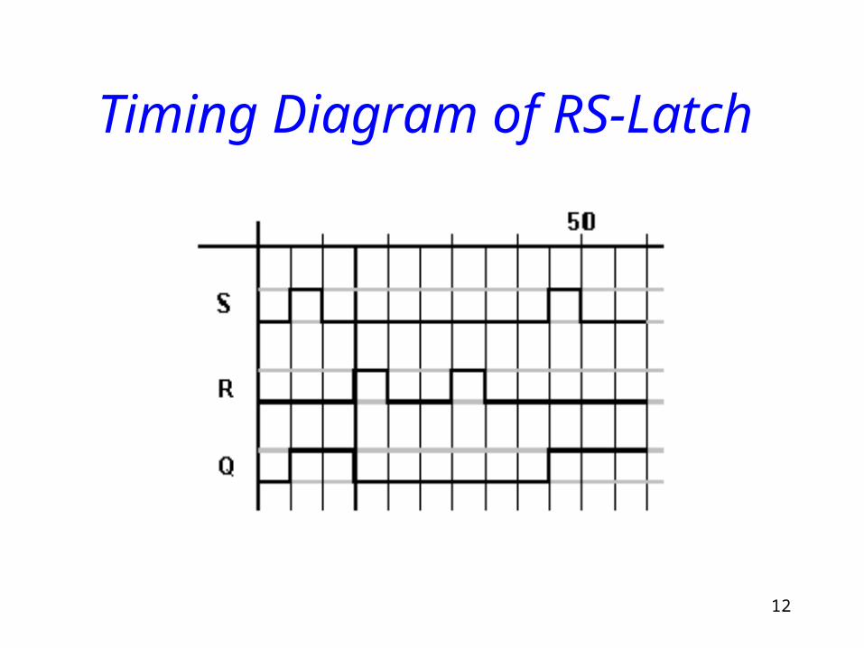
Timing Diagram of RS-Latch
13
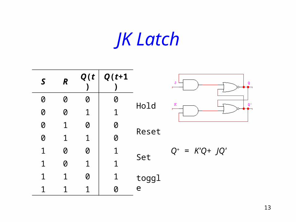
JK Latch
S R Q(t) Q(t+1)
0 0 0 0Hold
0 0 1 1
0 1 0 0Reset
0 1 1 0
1 0 0 1Set
Q+ = K'Q+ JQ'
1 0 1 1
1 1 0 1toggle
1 1 1 0
14
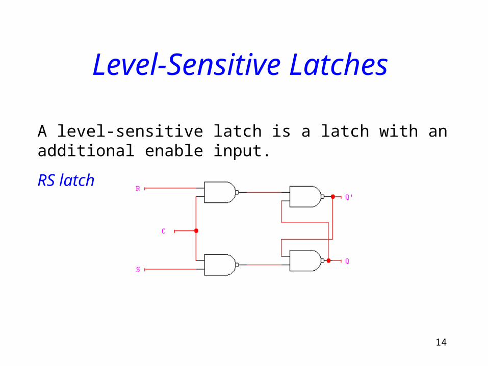
Level-Sensitive Latches
A level-sensitive latch is a latch with an additional enable input.
RS latch
15
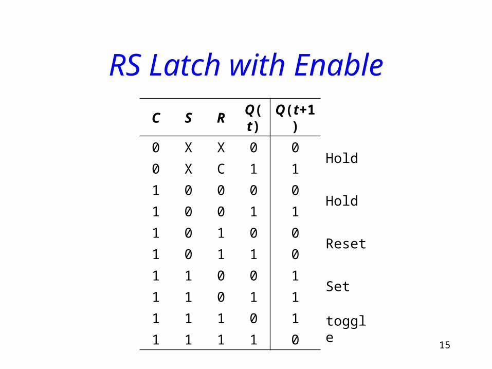
RS Latch with EnableC S R Q(t) Q(t+1)
0 X X 0 0Hold
0 X C 1 1
1 0 0 0 0Hold
1 0 0 1 1
1 0 1 0 0Reset
1 0 1 1 0
1 1 0 0 1Set
1 1 0 1 1
1 1 1 0 1toggle
1 1 1 1 0
16
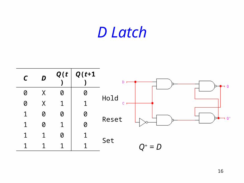
D Latch
C D Q(t) Q(t+1)
0 X 0 0Hold
0 X 1 1
1 0 0 0Reset
1 0 1 0
1 1 0 1Set
1 1 1 1
Q+ = D
17
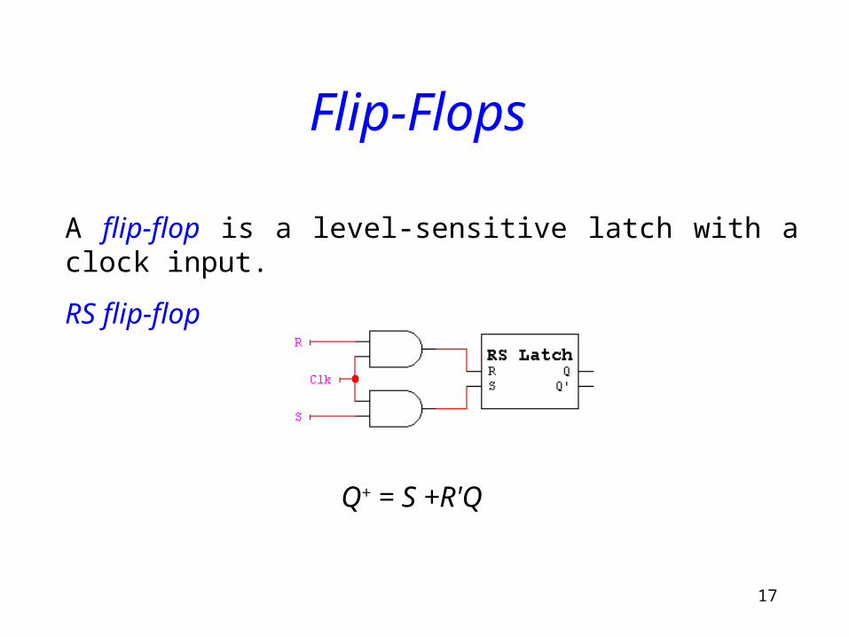
Flip-Flops
A flip-flop is a level-sensitive latch with a clock input.
RS flip-flop
Q+ = S +R'Q