sequential logic computer organization ellen walker hiram college figures from computer organization...
TRANSCRIPT

Sequential Logic
Computer Organization
Ellen Walker
Hiram College
Figures from Computer Organization and Design 3ed, D.A. Patterson & J.L. Hennessey, Morgan Kauffman © 2005 unless otherwise specified

Sequential Logic
• Combinational logic “forgets” its results when the inputs are no longer available
• Sequential logic “remembers” results until the next clock signal

A Memory Cell
~Q = 0 (or 1) Q = 1 (or 0)
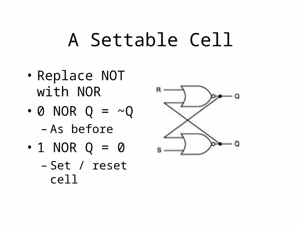
A Settable Cell
• Replace NOT with NOR
• 0 NOR Q = ~Q– As before
• 1 NOR Q = 0– Set / reset cell

Truth Table for SR Latch
R S Q ~Q
0 0 Q’ ~Q’
0 1 1 0
1 0 0 1
1 1 ? ?

Clock Signal
• Periodic alternation between 0 and 1
• Does not have to be evenly divided
• Example:
One periodRising edge Falling edge

Clocked D Latch
C D Q ~Q
0 0 Q’ ~Q’
0 1 Q’ ~Q’
1 0 0 1
1 1 1 0
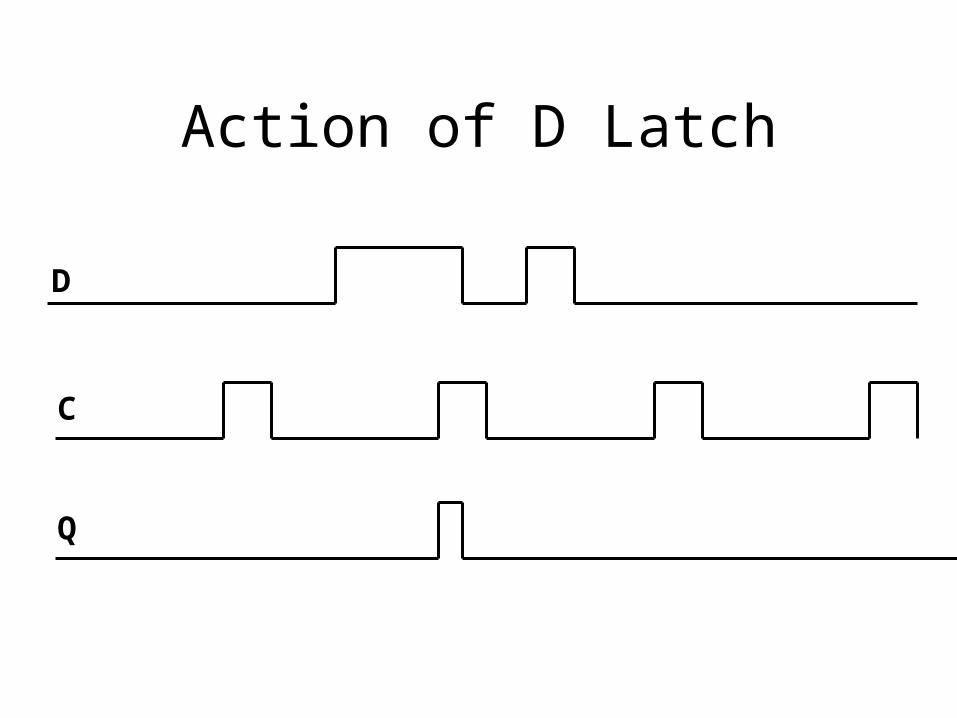
Action of D Latch
D
C
Q

Latch vs. Flip Flop
• Latch changes by level– As long as C is high, Q follows D
• Flip flop changes by edge– Q takes value of D at rising (or falling)
edge only

D Flip-Flop with Falling Edge Trigger
• When C is high, “master” follows D
• When C is low, “slave” follows Q of “master”
• When C is low, Q of “master” is locked in.

Action of D Flipflop
D
C
Q

Setup and Hold Time
• Setup time: Minimum time D must be stable before clock edge
• Hold time: Minimum time D must be stable after clock edge

Determining Clock Cycle
• Combinational logic must be done before D needs to be stable
• Therefore, (combinational logic + setup time + hold
time) < clock cycle

Other Flip Flops
• T (toggle): When T is set, flip-flop changes value at clock edge
• JK (very general ff)– When J=K=1 , toggles at edge– When J=1, K=0, sets at edge– When J=0, K=1, resets at edge– When J=K=0, holds value

Counter from T Flip Flops
• Low Order Bit:– T=1, clock = external signal
• Each additional bit:– T=1, clock = Q from lower bit– When lower bit falls, higher bit toggles
• Delay increases as # bits increase (“ripple effect”)

Sequential Circuit Allows Feedback
CombinationalLogic
D
C
QExternalinputs
Clock signal
Register from D Flip Flops
• One register is simply a set of D flip-flops, one per bit
• Data inputs are D’s
• Data outputs are Q’s and ~Q’s
• Clocks all tied together

Register File
• Several registers grouped together
• To read:– Input = register #– Output = register data
• To write:– Inputs = register #, register data,
clock (write signal)– Output = (none)

Implementing Read Ports

Implementing Write Ports

4x2 DRAM from D-FFs

State Machine
• Sequential logic holds state
• Combinational logic computes new state and output (based on old state)

Graphical Representation

Building a State Machine
• Determine the states and transitions
• Assign numbers to the states– If there are N states, you need log N flip
flops to hold the state number
• Create “next state” logic
• Create “output” logic

Example: Parity Checker
• One input, which sequentially gets the bits of a word
• One output, 0 if number of 1’s since reset is even, 1 if number of 1’s since reset is odd
• Asynchronous reset sets parity back to 0
Pattern Recognizer
• Input: Sequence of Bits
• Output: – If last 2 bits were “10” output is 1– If bit pattern “111” is found, output is 0 and
remains 0 no matter what– Otherwise, output is 0