serial adder
TRANSCRIPT
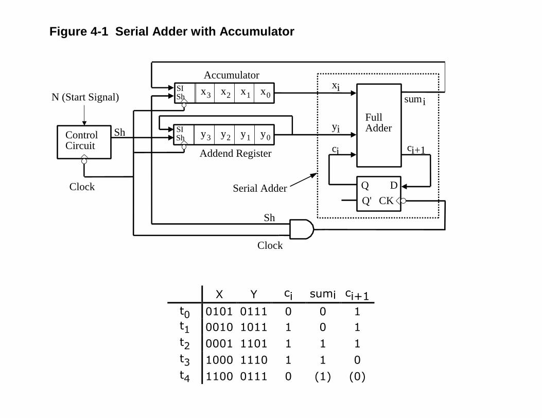
Figure 4-1 Serial Adder with Accumulator
X Y ci sumi ci+1t0 0101 0111 0 0 1t1 0010 1011 1 0 1t2 0001 1101 1 1 1t3 1000 1110 1 1 0t4 1100 0111 0 (1) (0)
y3 y2 y1 y0
FullAdder
Q DQ' CK
xi
yi
ci ci+1
sumix3 x2 x1 x0
Addend Register
Accumulator
ControlCircuit
Clock
N (Start Signal)SISh
Sh SISh
Sh
Clock
Serial Adder
S1
S2
S0
S3
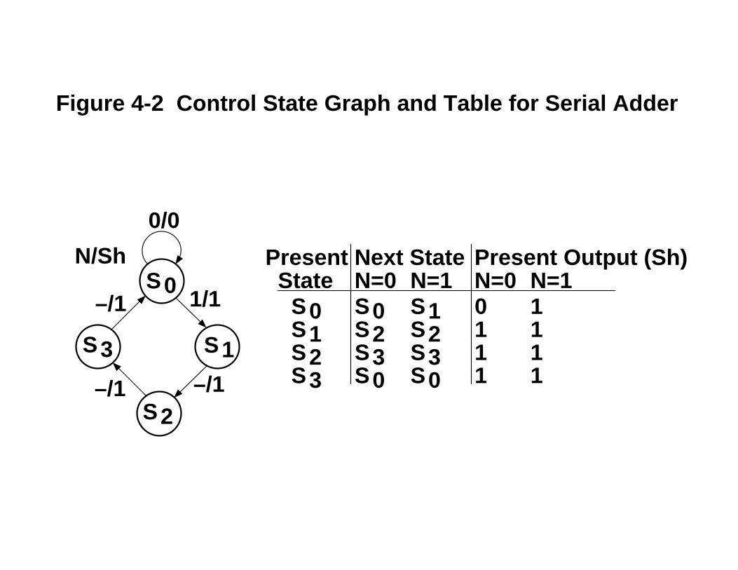
0/0
N/Sh
1/1
–/1
–/1
–/1
Next State Present Output (Sh)N=0 N=1 N=0 N=1
S0 S0 S1 0 1S1 S2 S2 1 1S2 S3 S3 1 1S3 S0 S0 1 1
Present State
Figure 4-2 Control State Graph and Table for Serial Adder

Constraints on Input Labels for Every State Sk (From Page 123-124)
1. If Ii and Ij are any pair of input labels on arcs exiting state Sk, then IiIj= 0 if i ≠ j.
2. If n arcs exit state Sk and the n arcs have input labels I1, I2, ..., In,respectively, then I1 + I2 + ... + In = 1.
Sk
Sp Sq
X1
X1'X2' X1'X2
(X1)(X1'X2') = 0(X1)(X1'X2) = 0(X1'X2')(X1'X2) = 0X1 + X1'X2' + X1'X2 =1
Inputs are X1 X2 X3(X1 = X2 = 1 not allowed)
000 001 010 011 100 101 110 111Sk Sk Sk Sq Sq Sp Sp – –
Sk
Sp Sq
X1 X2
X1'X2'
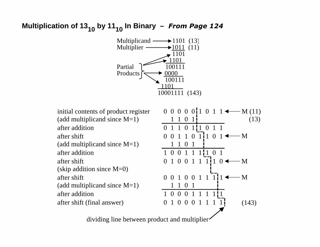
Multiplication of 1310 by 1110 In Binary – From Page 124
initial contents of product register 0 0 0 0 0 1 0 1 1(add multiplicand since M=1) 1 1 0 1after addition 0 1 1 0 1 1 0 1 1after shift 0 0 1 1 0 1 1 0 1(add multiplicand since M=1) 1 1 0 1after addition 1 0 0 1 1 1 1 0 1after shift 0 1 0 0 1 1 1 1 0(skip addition since M=0)after shift 0 0 1 0 0 1 1 1 1(add multiplicand since M=1) 1 1 0 1after addition 1 0 0 0 1 1 1 1 1after shift (final answer) 0 1 0 0 0 1 1 1 1
dividing line between product and multiplier
(143)
M (11) (13)
M
M
M
1011 1101
Multiplicand 1101 (13)Multiplier (11)
1101Partial 100111Products 0000 100111
1101 10001111 (143)
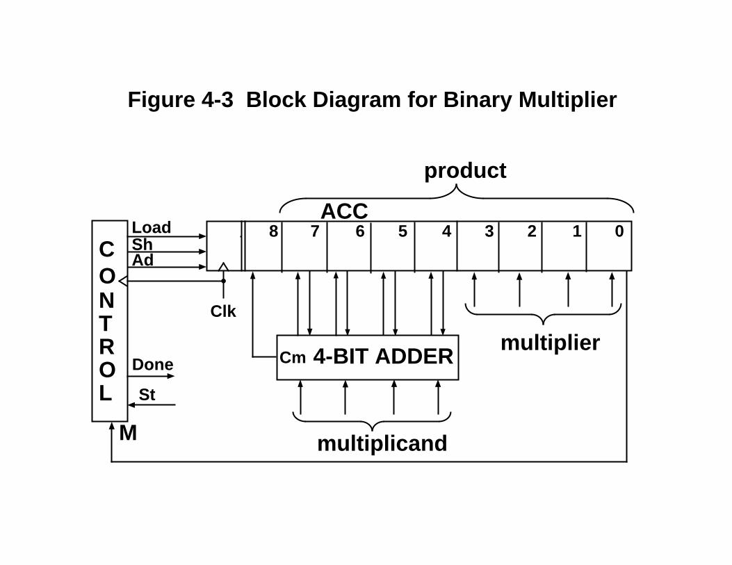
4-BIT ADDER
multiplicand
Cmmultiplier
product
CONTROL St
ShAd
M
Done
Load 4567 1 0238ACC
Clk
Figure 4-3 Block Diagram for Binary Multiplier
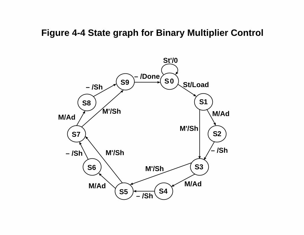
S1
S7
S9
S8
S0
S2
S3
S4S5
S6
St/Load
M/Ad
M'/Sh
– /Sh
M/Ad
M'/Sh
M'/Sh
M'/Sh
– /Done
– /ShM/Ad
– /Sh
M/Ad
– /Sh
St'/0
Figure 4-4 State graph for Binary Multiplier Control
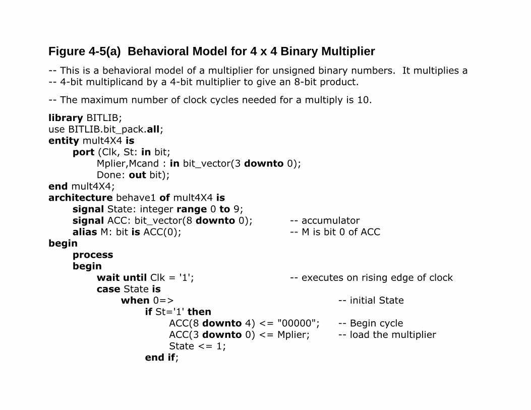
Figure 4-5(a) Behavioral Model for 4 x 4 Binary Multiplier-- This is a behavioral model of a multiplier for unsigned binary numbers. It multiplies a-- 4-bit multiplicand by a 4-bit multiplier to give an 8-bit product.
-- The maximum number of clock cycles needed for a multiply is 10.
library BITLIB;use BITLIB.bit_pack.all;entity mult4X4 is
port (Clk, St: in bit;Mplier,Mcand : in bit_vector(3 downto 0);Done: out bit);
end mult4X4;architecture behave1 of mult4X4 is
signal State: integer range 0 to 9;signal ACC: bit_vector(8 downto 0); -- accumulatoralias M: bit is ACC(0); -- M is bit 0 of ACC
beginprocessbegin
wait until Clk = '1'; -- executes on rising edge of clockcase State is
when 0=> -- initial Stateif St='1' then
ACC(8 downto 4) <= "00000"; -- Begin cycleACC(3 downto 0) <= Mplier; -- load the multiplierState <= 1;
end if;
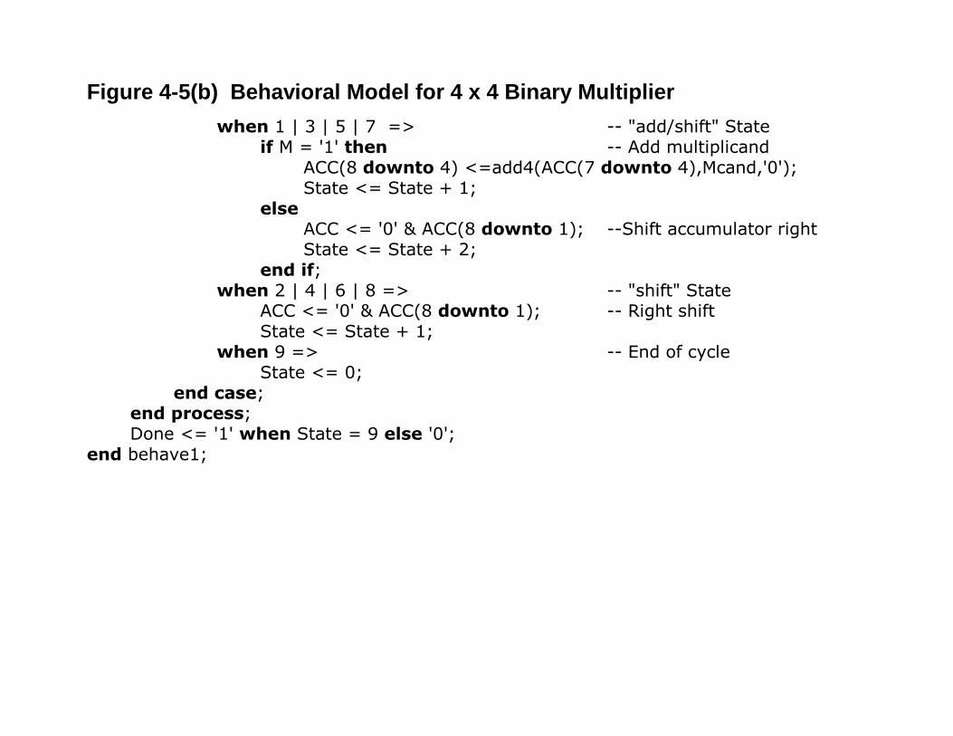
Figure 4-5(b) Behavioral Model for 4 x 4 Binary Multiplierwhen 1 | 3 | 5 | 7 => -- "add/shift" State
if M = '1' then -- Add multiplicandACC(8 downto 4) <=add4(ACC(7 downto 4),Mcand,'0');State <= State + 1;
elseACC <= '0' & ACC(8 downto 1); --Shift accumulator rightState <= State + 2;
end if;when 2 | 4 | 6 | 8 => -- "shift" State
ACC <= '0' & ACC(8 downto 1); -- Right shiftState <= State + 1;
when 9 => -- End of cycleState <= 0;
end case;end process;Done <= '1' when State = 9 else '0';
end behave1;
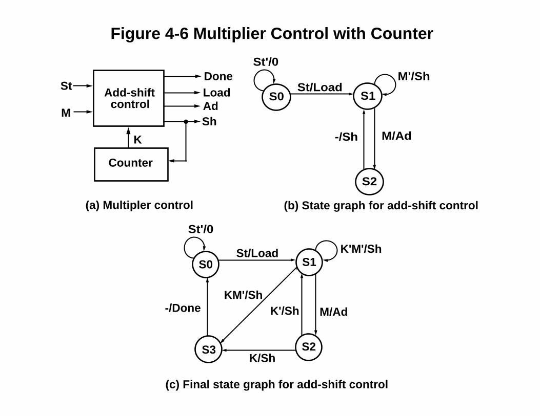
Add-shift control
Counter
DoneLoadAdSh
K
St
MS0 S1
S2
St/Load
M/Ad-/Sh
M'/Sh
(a) Multipler control (b) State graph for add-shift control
St/Load
M/Ad
K/Sh
KM'/ShK'/Sh-/Done
S0 S1
S2S3
(c) Final state graph for add-shift control
K'M'/Sh
St'/0
St'/0
Figure 4-6 Multiplier Control with Counter
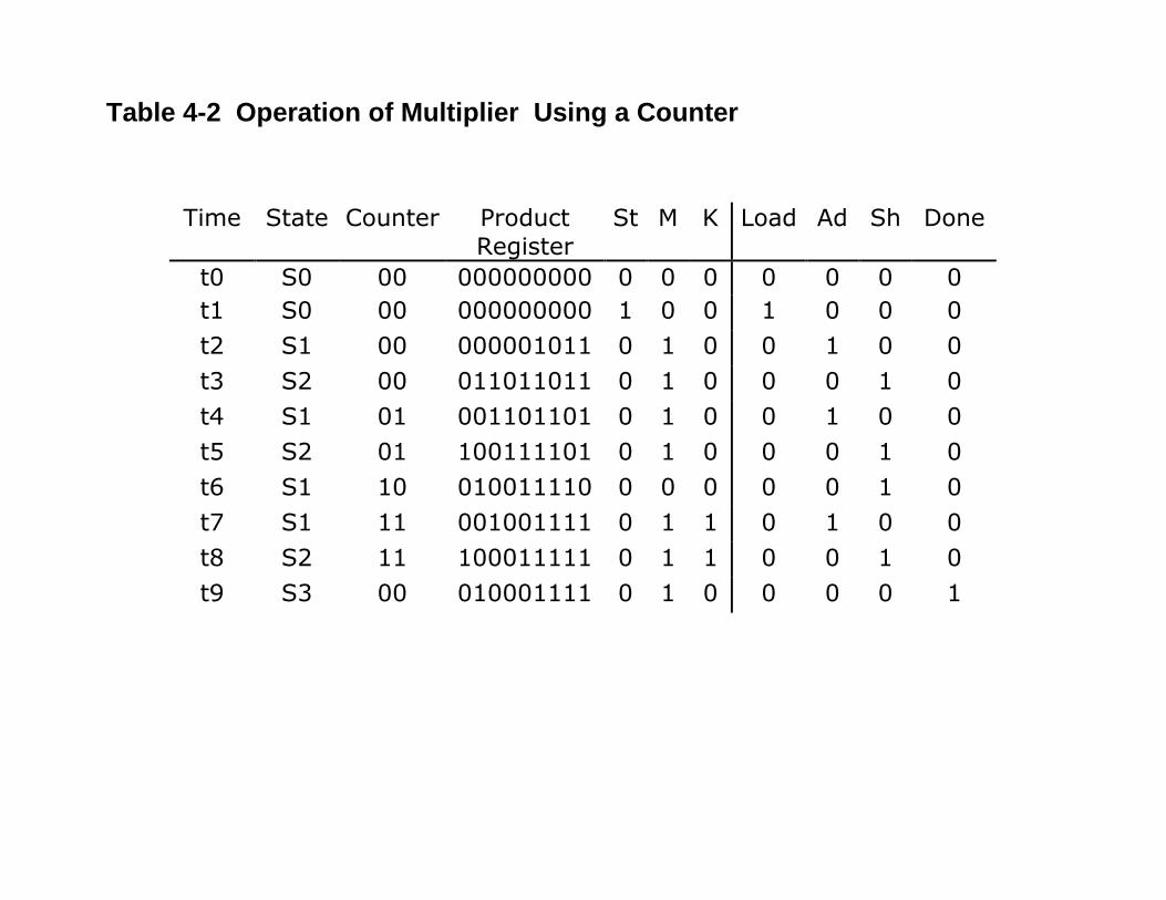
Table 4-2 Operation of Multiplier Using a Counter
Time State Counter ProductRegister
St M K Load Ad Sh Done
t0 S0 00 000000000 0 0 0 0 0 0 0t1 S0 00 000000000 1 0 0 1 0 0 0t2 S1 00 000001011 0 1 0 0 1 0 0t3 S2 00 011011011 0 1 0 0 0 1 0t4 S1 01 001101101 0 1 0 0 1 0 0t5 S2 01 100111101 0 1 0 0 0 1 0t6 S1 10 010011110 0 0 0 0 0 1 0t7 S1 11 001001111 0 1 1 0 1 0 0t8 S2 11 100011111 0 1 1 0 0 1 0t9 S3 00 010001111 0 1 0 0 0 0 1
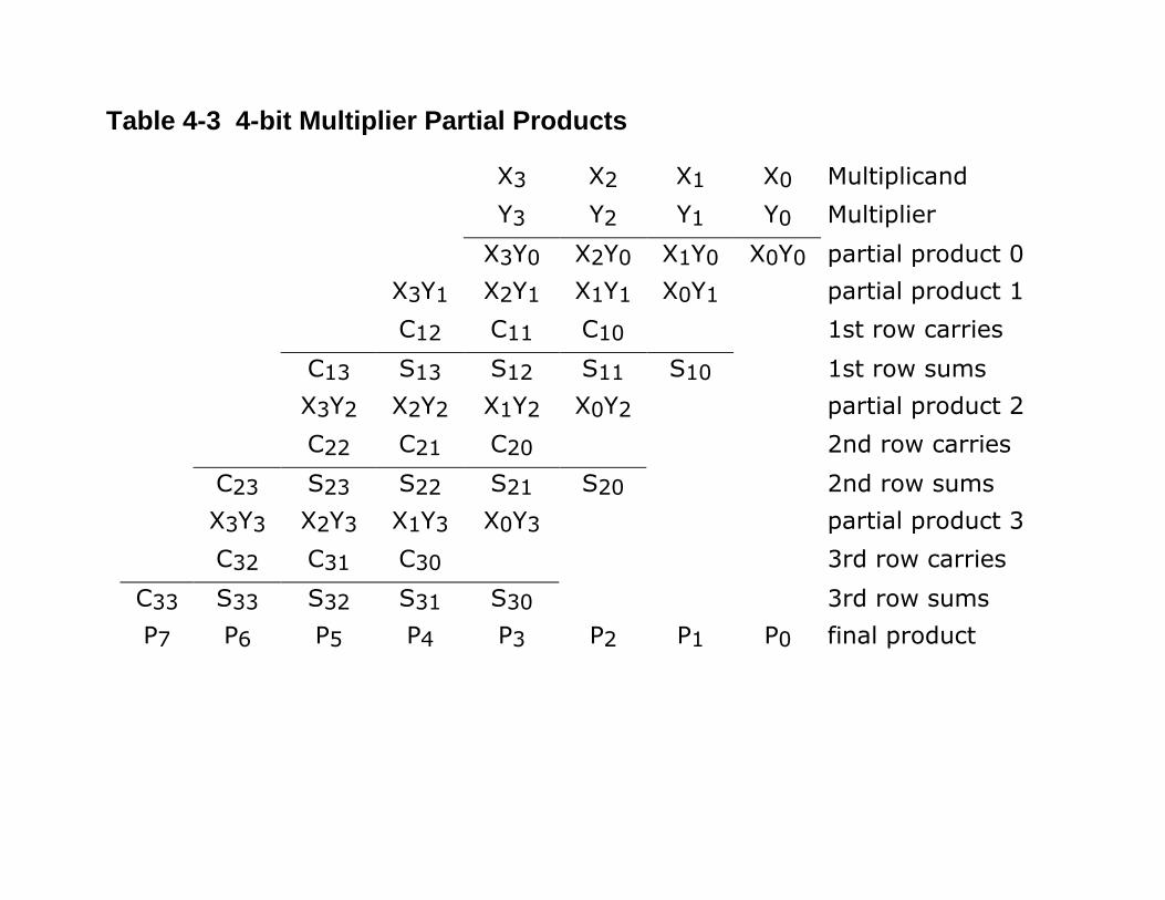
Table 4-3 4-bit Multiplier Partial Products
X3 X2 X1 X0 MultiplicandY3 Y2 Y1 Y0 Multiplier
X3Y0 X2Y0 X1Y0 X0Y0 partial product 0X3Y1 X2Y1 X1Y1 X0Y1 partial product 1C12 C11 C10 1st row carries
C13 S13 S12 S11 S10 1st row sumsX3Y2 X2Y2 X1Y2 X0Y2 partial product 2C22 C21 C20 2nd row carries
C23 S23 S22 S21 S20 2nd row sumsX3Y3 X2Y3 X1Y3 X0Y3 partial product 3C32 C31 C30 3rd row carries
C33 S33 S32 S31 S30 3rd row sumsP7 P6 P5 P4 P3 P2 P1 P0 final product
HAFAFAHA
HAFAFAFA
HAFAFAFA
X0Y0X3Y0 X2Y0 X1Y0
X3Y1 X2Y1 X1Y1 X0Y1
X3Y2 X2Y2 X1Y2 X0Y2
X3Y3 X2Y3 X1Y3 X0Y3
P7 P6 P5 P4 P3
P2
P1
P0
S10S11S12S13
C12 C11 C10
C13
C22 C21 C20
C23
C32 C31 C30
C33
S21S22S23
S30S31S32S33
S20
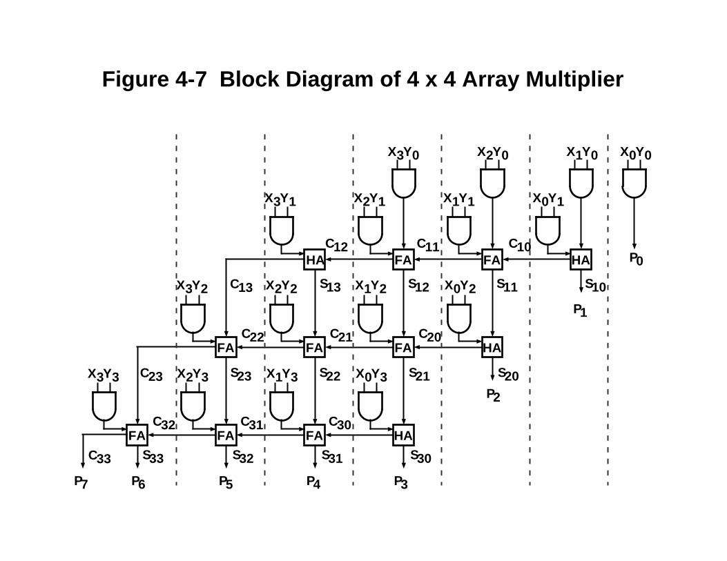
Figure 4-7 Block Diagram of 4 x 4 Array Multiplier
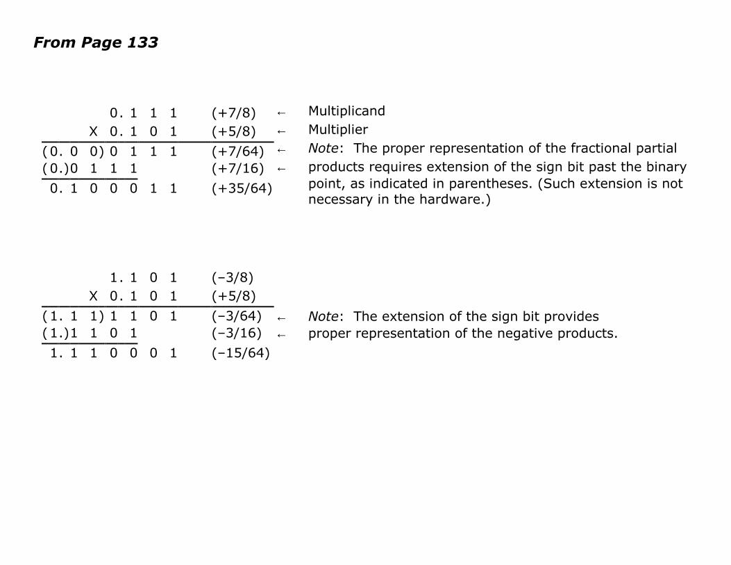
From Page 133
0. 1 1 1 (+7/8)X 0. 1 0 1 (+5/8)
(0. 0 0) 0 1 1 1 (+7/64)(0.)0 1 1 1 (+7/16)0. 1 0 0 0 1 1 (+35/64)
← Multiplicand← Multiplier← Note: The proper representation of the fractional partial← products requires extension of the sign bit past the binary
point, as indicated in parentheses. (Such extension is notnecessary in the hardware.)
1. 1 0 1 (–3/8)X 0. 1 0 1 (+5/8)
(1. 1 1) 1 1 0 1 (–3/64)(1.)1 1 0 1 (–3/16)1. 1 1 0 0 0 1 (–15/64)
← Note: The extension of the sign bit provides← proper representation of the negative products.
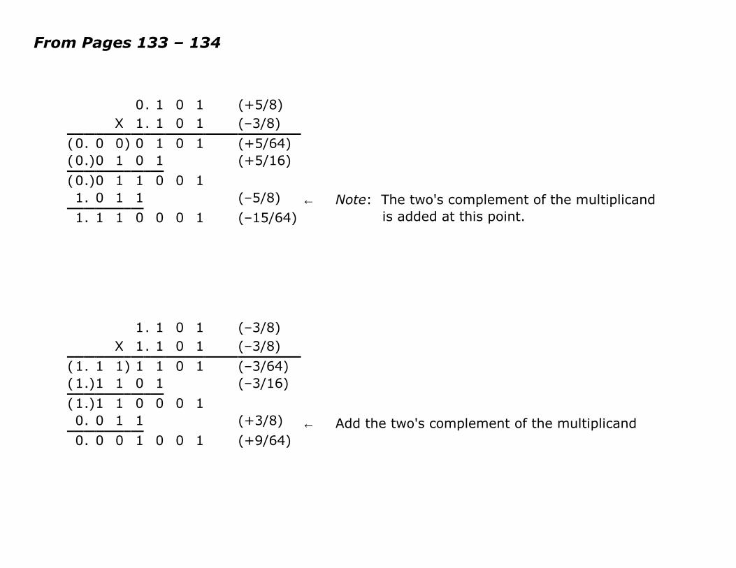
From Pages 133 – 134
0. 1 0 1 (+5/8)X 1. 1 0 1 (–3/8)
(0. 0 0) 0 1 0 1 (+5/64)(0.)0 1 0 1 (+5/16)(0.)0 1 1 0 0 11. 0 1 1 (–5/8)1. 1 1 0 0 0 1 (–15/64)
← Note: The two's complement of the multiplicandis added at this point.
1. 1 0 1 (–3/8)X 1. 1 0 1 (–3/8)
(1. 1 1) 1 1 0 1 (–3/64)(1.)1 1 0 1 (–3/16)(1.)1 1 0 0 0 10. 0 1 1 (+3/8)0. 0 0 1 0 0 1 (+9/64)
← Add the two's complement of the multiplicand
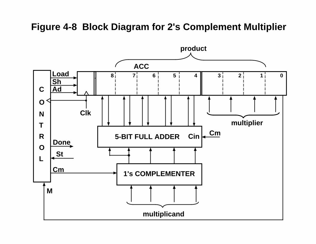
4567 1 0238
ACC
multiplier
product
5-BIT FULL ADDER Cin
1's COMPLEMENTER
multiplicand
Cm
C
O
N
T
R
O
LSt
ShAd
Done
Load
M
Cm
Clk
Figure 4-8 Block Diagram for 2's Complement Multiplier

S1
S7
S8
S2
S3
S4S5
S6
St/Load
M/Ad
M'/Sh
– /Sh
M/Ad
M'/Sh
M'/Sh
- /Done
– /Sh
M/Ad
– /Sh
M/Cm Ad
M'/0
St'/0S0
Figure 4-9 State Graph for 2's Complement Multiplier
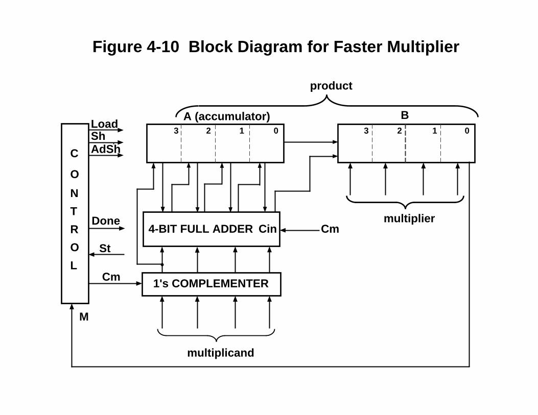
0123 1 023
C
O
N
T
R
O
L
A (accumulator)
4-BIT FULL ADDER
1's COMPLEMENTER
multiplicand
St
ShAdSh
Cm
Cm
product
Done
M
multiplier
Load
Cin
B
Figure 4-10 Block Diagram for Faster Multiplier
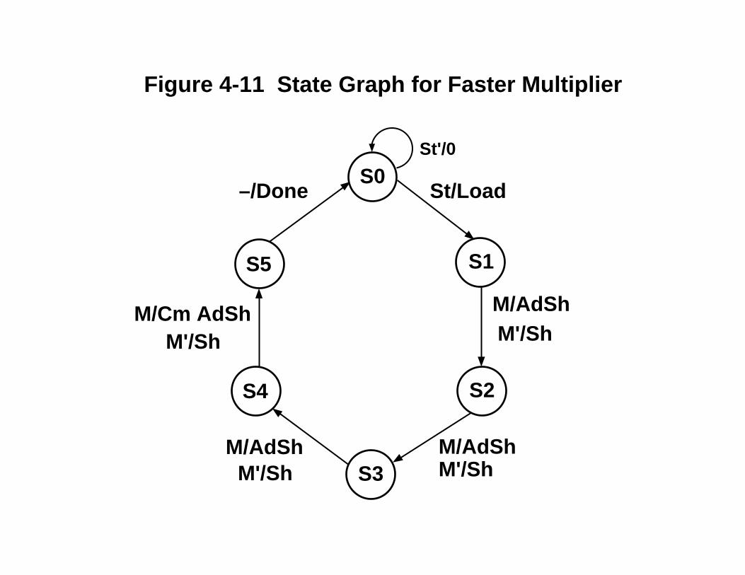
S0
S1
S2
S3
S4
S5
St/Load
M/AdShM'/Sh
M/AdShM/AdSh
M/Cm AdSh
M'/Sh
M'/Sh
M'/Sh
–/Done
Figure 4-11 State Graph for Faster Multiplier
St'/0

Figure 4-12(a) Behavioral Model for 2’s Complement Multiplierlibrary BITLIB;use BITLIB.bit_pack.all;
entity mult2C isport (CLK, St: in bit;
Mplier,Mcand : in bit_vector(3 downto 0);Product: out bit_vector (6 downto 0);Done: out bit);
end mult2C;
architecture behave1 of mult2C issignal State : integer range 0 to 5;signal A, B: bit_vector(3 downto 0);alias M: bit is B(0);
beginprocessvariable addout: bit_vector(4 downto 0);begin
wait until CLK = '1';case State is
when 0=> -- initial Stateif St='1' then
A <= "0000"; -- Begin cycleB <= Mplier; -- load the multiplierState <= 1;
end if;

Figure 4-12(b) Behavioral Model for 2’s Complement Multiplierwhen 1 | 2 | 3 => -- "add/shift" State
if M = '1' thenaddout := add4(A,Mcand,'0'); -- Add multiplicand to A and shiftA <= Mcand(3) & addout(3 downto 1);B <= addout(0) & B(3 downto 1);
elseA <= A(3) & A(3 downto 1); -- Arithmetic right shiftB <= A(0) & B(3 downto 1);
end if;State <= State + 1;
when 4 => -- add complement if sign bitif M = '1' then -- of multiplier is 1
addout := add4(A, not Mcand,'1');A <= not Mcand(3) & addout(3 downto 1);B <= addout(0) & B(3 downto 1);
elseA <= A(3) & A(3 downto 1); -- Arithmetic right shiftB <= A(0) & B(3 downto 1);
end if;State <= 5; wait for 0 ns;
Done <= '1'; Product <= A(2 downto 0) & B;when 5 => -- output product
State <= 0;Done <= '0';
end case;end process;
end behave1;
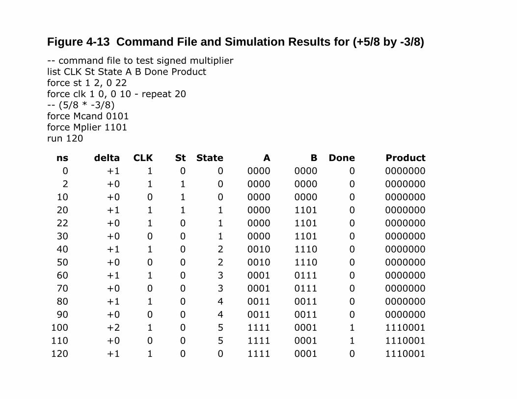
Figure 4-13 Command File and Simulation Results for (+5/8 by -3/8)-- command file to test signed multiplierlist CLK St State A B Done Productforce st 1 2, 0 22force clk 1 0, 0 10 - repeat 20-- (5/8 * -3/8)force Mcand 0101force Mplier 1101run 120
ns delta CLK St State A B Done Product0 +1 1 0 0 0000 0000 0 00000002 +0 1 1 0 0000 0000 0 0000000
10 +0 0 1 0 0000 0000 0 000000020 +1 1 1 1 0000 1101 0 000000022 +0 1 0 1 0000 1101 0 000000030 +0 0 0 1 0000 1101 0 000000040 +1 1 0 2 0010 1110 0 000000050 +0 0 0 2 0010 1110 0 000000060 +1 1 0 3 0001 0111 0 000000070 +0 0 0 3 0001 0111 0 000000080 +1 1 0 4 0011 0011 0 000000090 +0 0 0 4 0011 0011 0 0000000
100 +2 1 0 5 1111 0001 1 1110001110 +0 0 0 5 1111 0001 1 1110001120 +1 1 0 0 1111 0001 0 1110001
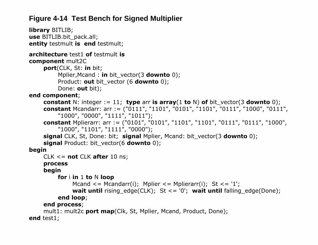
Figure 4-14 Test Bench for Signed Multiplierlibrary BITLIB;use BITLIB.bit_pack.all;entity testmult is end testmult;
architecture test1 of testmult iscomponent mult2C
port(CLK, St: in bit;Mplier,Mcand : in bit_vector(3 downto 0);Product: out bit_vector (6 downto 0);Done: out bit);
end component;constant N: integer := 11; type arr is array(1 to N) of bit_vector(3 downto 0);constant Mcandarr: arr := ("0111", "1101", "0101", "1101", "0111", "1000", "0111",
"1000", "0000", "1111", "1011");constant Mplierarr: arr := ("0101", "0101", "1101", "1101", "0111", "0111", "1000",
"1000", "1101", "1111", "0000");signal CLK, St, Done: bit; signal Mplier, Mcand: bit_vector(3 downto 0);signal Product: bit_vector(6 downto 0);
beginCLK <= not CLK after 10 ns;processbegin
for i in 1 to N loopMcand <= Mcandarr(i); Mplier <= Mplierarr(i); St <= '1';wait until rising_edge(CLK); St <= '0'; wait until falling_edge(Done);
end loop;end process;mult1: mult2c port map(Clk, St, Mplier, Mcand, Product, Done);
end test1;
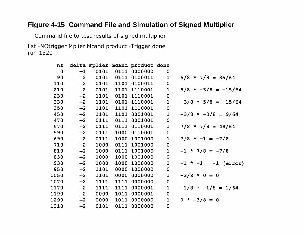
Figure 4-15 Command File and Simulation of Signed Multiplier-- Command file to test results of signed multiplier
list -NOtrigger Mplier Mcand product -Trigger donerun 1320
ns delta mplier mcand product done 0 +1 0101 0111 0000000 0 90 +2 0101 0111 0100011 1 5/8 * 7/8 = 35/64 110 +2 0101 1101 0100011 0 210 +2 0101 1101 1110001 1 5/8 * -3/8 = -15/64 230 +2 1101 0101 1110001 0 330 +2 1101 0101 1110001 1 -3/8 * 5/8 = -15/64 350 +2 1101 1101 1110001 0 450 +2 1101 1101 0001001 1 -3/8 * -3/8 = 9/64 470 +2 0111 0111 0001001 0 570 +2 0111 0111 0110001 1 7/8 * 7/8 = 49/64 590 +2 0111 1000 0110001 0 690 +2 0111 1000 1001000 1 7/8 * -1 = -7/8 710 +2 1000 0111 1001000 0 810 +2 1000 0111 1001000 1 -1 * 7/8 = -7/8 830 +2 1000 1000 1001000 0 930 +2 1000 1000 1000000 1 -1 * -1 = -1 (error) 950 +2 1101 0000 1000000 0 1050 +2 1101 0000 0000000 1 -3/8 * 0 = 0 1070 +2 1111 1111 0000000 0 1170 +2 1111 1111 0000001 1 -1/8 * -1/8 = 1/64 1190 +2 0000 1011 0000001 0 1290 +2 0000 1011 0000000 1 0 * -3/8 = 0 1310 +2 0101 0111 0000000 0
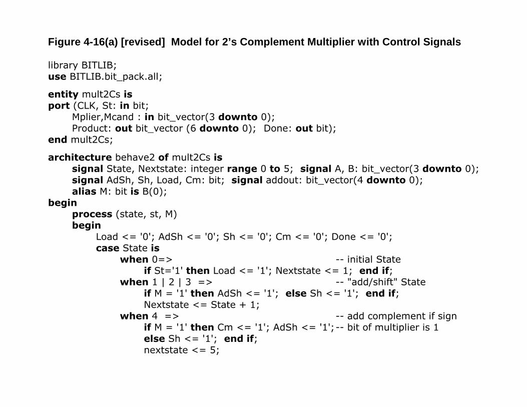
Figure 4-16(a) [revised] Model for 2’s Complement Multiplier with Control Signals
library BITLIB;use BITLIB.bit_pack.all;
entity mult2Cs isport (CLK, St: in bit;
Mplier,Mcand : in bit_vector(3 downto 0);Product: out bit_vector (6 downto 0); Done: out bit);
end mult2Cs;
architecture behave2 of mult2Cs issignal State, Nextstate: integer range 0 to 5; signal A, B: bit_vector(3 downto 0);signal AdSh, Sh, Load, Cm: bit; signal addout: bit_vector(4 downto 0);alias M: bit is B(0);
beginprocess (state, st, M)begin
Load <= '0'; AdSh <= '0'; Sh <= '0'; Cm <= '0'; Done <= '0';case State is
when 0=> -- initial Stateif St='1' then Load <= '1'; Nextstate <= 1; end if;
when 1 | 2 | 3 => -- "add/shift" Stateif M = '1' then AdSh <= '1'; else Sh <= '1'; end if;Nextstate <= State + 1;
when 4 => -- add complement if signif M = '1' then Cm <= '1'; AdSh <= '1';-- bit of multiplier is 1else Sh <= '1'; end if;nextstate <= 5;
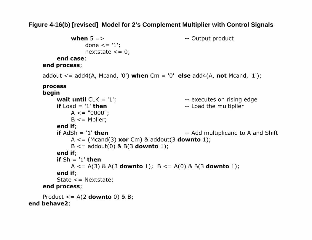
Figure 4-16(b) [revised] Model for 2’s Complement Multiplier with Control Signals
when 5 => -- Output productdone <= '1';nextstate <= 0;
end case;end process;
addout <= add4(A, Mcand, '0') when Cm = '0' else add4(A, not Mcand, '1');
processbegin
wait until CLK = '1'; -- executes on rising edgeif Load = '1' then -- Load the multiplier
A <= "0000";B <= Mplier;
end if;if AdSh = '1' then -- Add multiplicand to A and Shift
A <= (Mcand(3) xor Cm) & addout(3 downto 1);B <= addout(0) & B(3 downto 1);
end if;if Sh = '1' then
A <= A(3) & A(3 downto 1); B <= A(0) & B(3 downto 1);end if;State <= Nextstate;
end process;
Product <= A(2 downto 0) & B;end behave2;
Done
Co
Sh
74163
D3 D2 D1 D0
Q3 Q2 Q1 Q0
AdShSt
M
LOGIC
1P1Ld1Clr1
0 1 0 0
CLK
Load
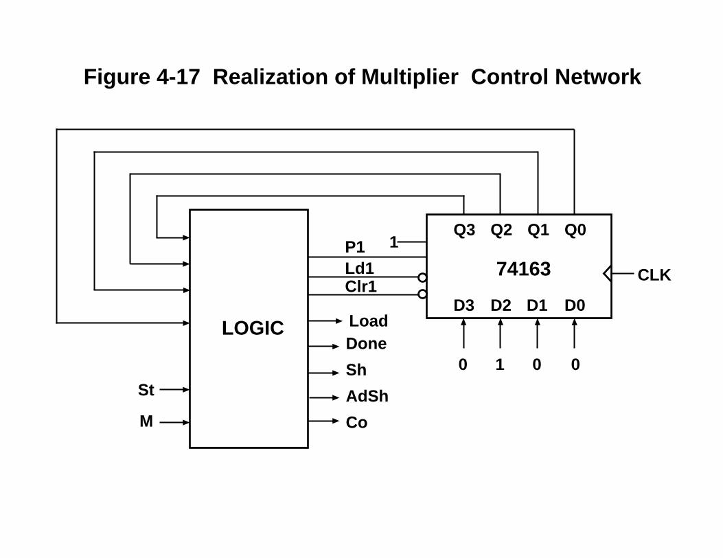
Figure 4-17 Realization of Multiplier Control Network
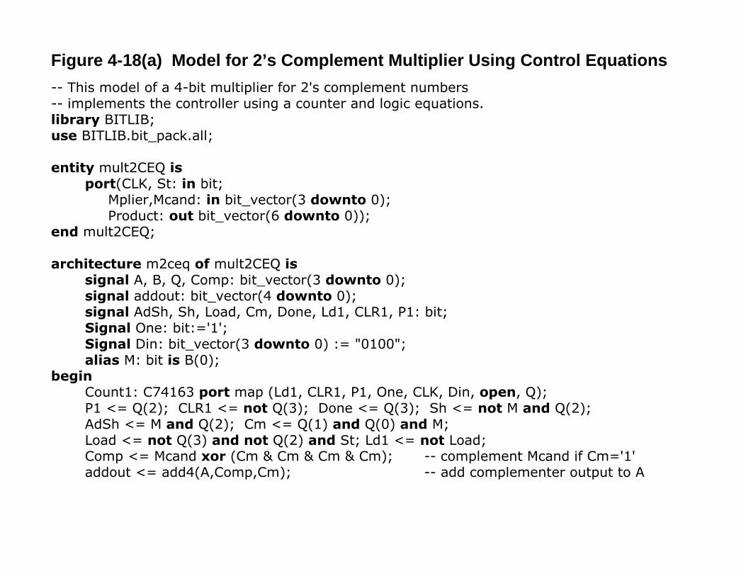
Figure 4-18(a) Model for 2’s Complement Multiplier Using Control Equations-- This model of a 4-bit multiplier for 2's complement numbers-- implements the controller using a counter and logic equations.library BITLIB;use BITLIB.bit_pack.all;
entity mult2CEQ is port(CLK, St: in bit;
Mplier,Mcand: in bit_vector(3 downto 0); Product: out bit_vector(6 downto 0));
end mult2CEQ;
architecture m2ceq of mult2CEQ issignal A, B, Q, Comp: bit_vector(3 downto 0);signal addout: bit_vector(4 downto 0);signal AdSh, Sh, Load, Cm, Done, Ld1, CLR1, P1: bit;Signal One: bit:='1';Signal Din: bit_vector(3 downto 0) := "0100";alias M: bit is B(0);
beginCount1: C74163 port map (Ld1, CLR1, P1, One, CLK, Din, open, Q);P1 <= Q(2); CLR1 <= not Q(3); Done <= Q(3); Sh <= not M and Q(2);AdSh <= M and Q(2); Cm <= Q(1) and Q(0) and M;Load <= not Q(3) and not Q(2) and St; Ld1 <= not Load;Comp <= Mcand xor (Cm & Cm & Cm & Cm); -- complement Mcand if Cm='1'addout <= add4(A,Comp,Cm); -- add complementer output to A
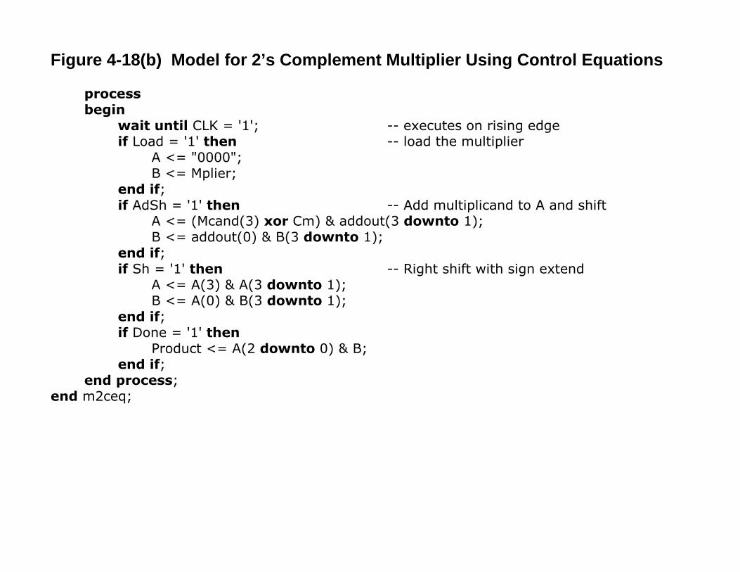
Figure 4-18(b) Model for 2’s Complement Multiplier Using Control Equations
processbegin
wait until CLK = '1'; -- executes on rising edgeif Load = '1' then -- load the multiplier
A <= "0000";B <= Mplier;
end if;if AdSh = '1' then -- Add multiplicand to A and shift
A <= (Mcand(3) xor Cm) & addout(3 downto 1);B <= addout(0) & B(3 downto 1);
end if;if Sh = '1' then -- Right shift with sign extend
A <= A(3) & A(3 downto 1);B <= A(0) & B(3 downto 1);
end if;if Done = '1' then
Product <= A(2 downto 0) & B;end if;
end process;end m2ceq;
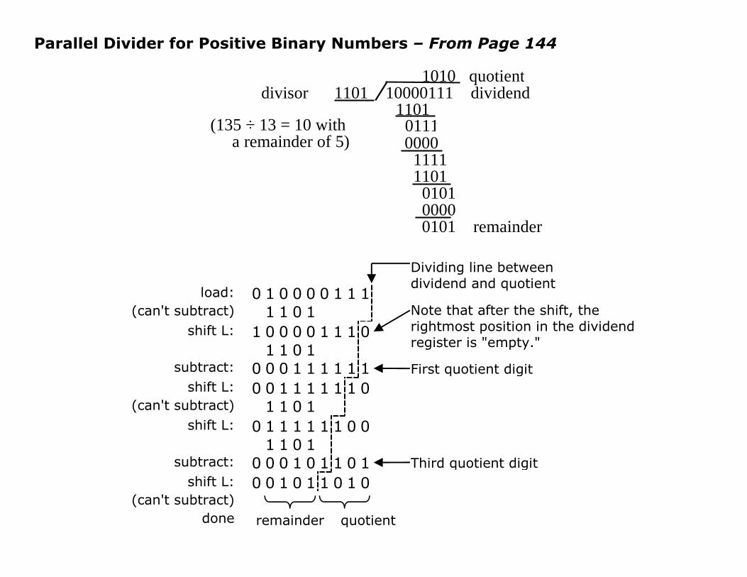
Parallel Divider for Positive Binary Numbers – From Page 144
1010 quotientdivisor 1101 10000111 dividend 1101 0111 0000 1111 1101 0101 0000 0101 remainder
(135 ÷ 13 = 10 with a remainder of 5)
load: 0 1 0 0 0 0 1 1 1(can't subtract) 1 1 0 1
shift L: 1 0 0 0 0 1 1 1 01 1 0 1
subtract: 0 0 0 1 1 1 1 1 1shift L: 0 0 1 1 1 1 1 1 0
(can't subtract) 1 1 0 1shift L: 0 1 1 1 1 1 1 0 0
1 1 0 1subtract: 0 0 0 1 0 1 1 0 1
shift L: 0 0 1 0 1 1 0 1 0(can't subtract)
done
Dividing line betweendividend and quotient
Note that after the shift, therightmost position in the dividendregister is "empty."
First quotient digit
Third quotient digit
remainder quotient
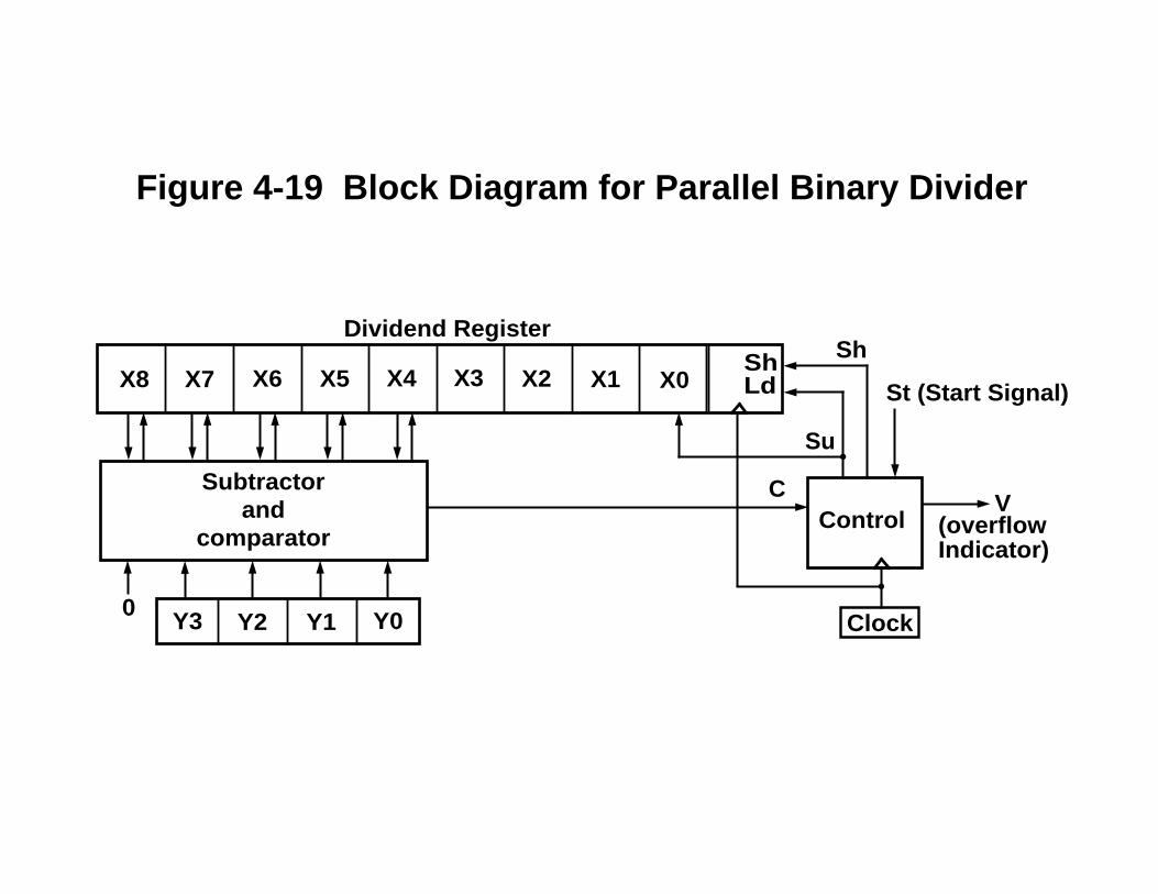
X8 X7 X6 X5 X3 X2 X1 X0ShLdX4
Clock
Control
Subtractorand
comparator
Dividend Register
Y3 Y2 Y1 Y00
V(overflowIndicator)
St (Start Signal)
Sh
C
Su
Figure 4-19 Block Diagram for Parallel Binary Divider

Figure 4-20 State Diagram for Divider Control Circuit
St'/0St/Load
C'/Sh C/Su
C'/Sh
C/SuC'/Sh
C/Su
C'/Sh
C'/0C/Su
S0 S1 S2
S5 S4 S3
C/V(stop)
StC StCState 00 01 11 10 00 01 11 10S0 S0 S0 S1 S1 0 0 Load LoadS1 S2 S0 – – Sh V – –S2 S3 S2 – – Sh Su – –S3 S4 S3 – – Sh Su – –S4 S5 S4 – – Sh Su – –S5 S0 S0 – – 0 Su – –
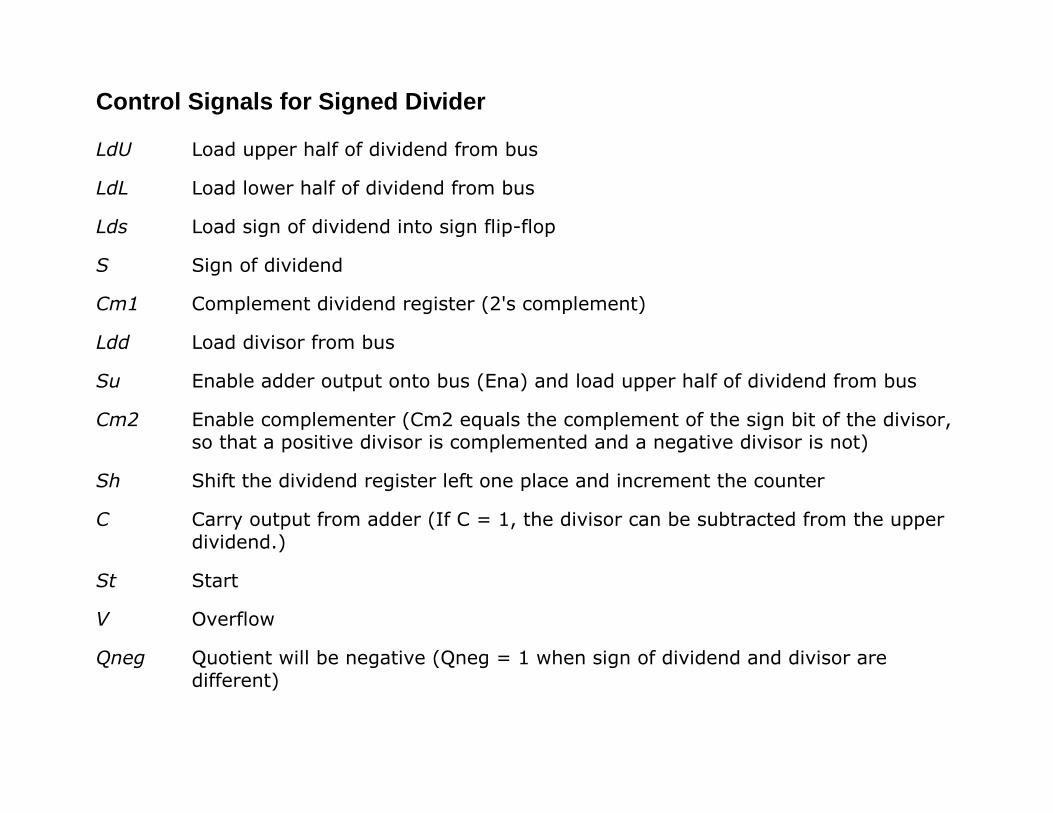
Control Signals for Signed Divider
LdU Load upper half of dividend from bus
LdL Load lower half of dividend from bus
Lds Load sign of dividend into sign flip-flop
S Sign of dividend
Cm1 Complement dividend register (2's complement)
Ldd Load divisor from bus
Su Enable adder output onto bus (Ena) and load upper half of dividend from bus
Cm2 Enable complementer (Cm2 equals the complement of the sign bit of the divisor,so that a positive divisor is complemented and a negative divisor is not)
Sh Shift the dividend register left one place and increment the counter
C Carry output from adder (If C = 1, the divisor can be subtracted from the upperdividend.)
St Start
V Overflow
Qneg Quotient will be negative (Qneg = 1 when sign of dividend and divisor aredifferent)
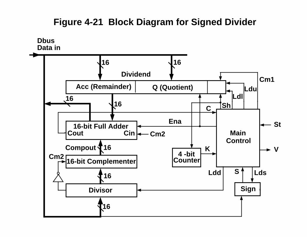
16-bit Full Adder
16-bit Complementer
Divisor
MainControl
Counter
Sign
16
Acc (Remainder) Q (Quotient)
Dividend
16 16
16
16
Cm2
St
VK
16
Cout
Ena
Cin MainControl
C ShLdl
LduCm1
Data in
Ldd Lds
Cm2
Compout
Dbus
16
4 -bit
S
Figure 4-21 Block Diagram for Signed Divider
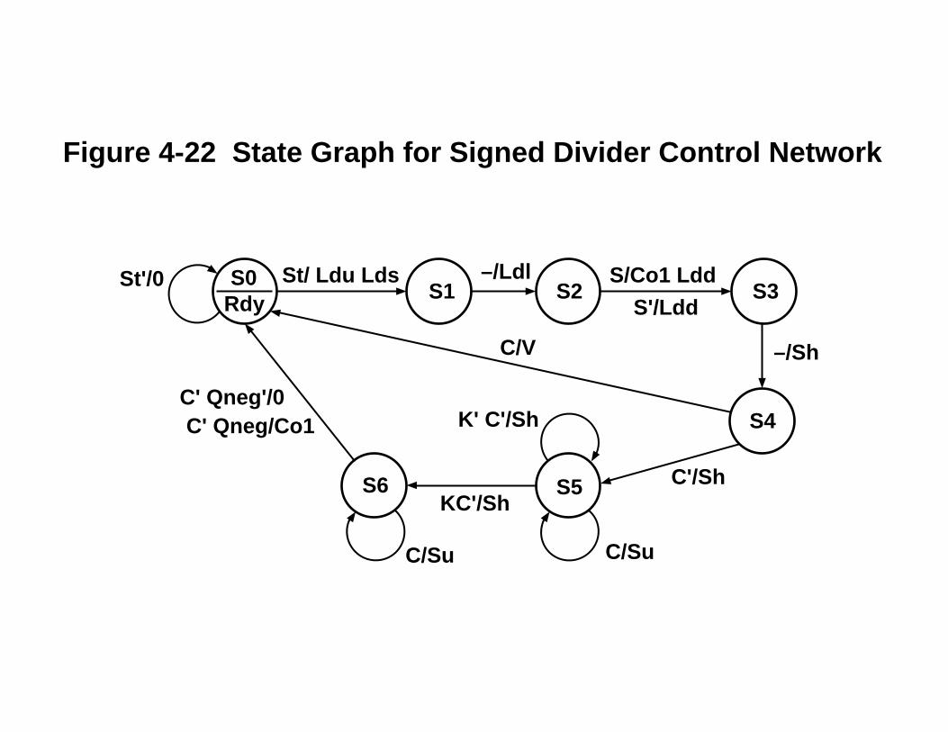
–/Ldl S/Co1 Ldd
S'/Ldd
–/ShC/V
St/ Ldu Lds
C/Su
K' C'/Sh
KC'/Sh
C/Su
C' Qneg'/0C' Qneg/Co1
S0S1 S2 S3
S5S6
S4
C'/Sh
St'/0Rdy
Figure 4-22 State Graph for Signed Divider Control Network
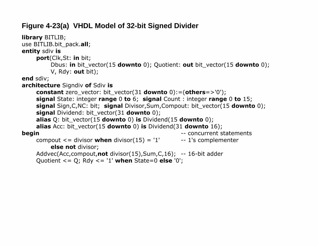
Figure 4-23(a) VHDL Model of 32-bit Signed Dividerlibrary BITLIB;use BITLIB.bit_pack.all;entity sdiv is
port(Clk,St: in bit;Dbus: in bit_vector(15 downto 0); Quotient: out bit_vector(15 downto 0);V, Rdy: out bit);
end sdiv;architecture Signdiv of Sdiv is
constant zero_vector: bit_vector(31 downto 0):=(others=>'0');signal State: integer range 0 to 6; signal Count : integer range 0 to 15;signal Sign,C,NC: bit; signal Divisor,Sum,Compout: bit_vector(15 downto 0);signal Dividend: bit_vector(31 downto 0);alias Q: bit_vector(15 downto 0) is Dividend(15 downto 0);alias Acc: bit_vector(15 downto 0) is Dividend(31 downto 16);
begin -- concurrent statementscompout <= divisor when divisor(15) = '1' -- 1's complementer
else not divisor;Addvec(Acc,compout,not divisor(15),Sum,C,16); -- 16-bit adderQuotient <= Q; Rdy <= '1' when State=0 else '0';
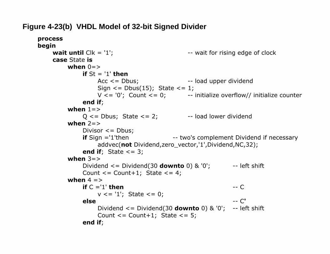
Figure 4-23(b) VHDL Model of 32-bit Signed Dividerprocessbegin
wait until Clk = '1'; -- wait for rising edge of clockcase State is
when 0=>if St = '1' then
Acc <= Dbus; -- load upper dividendSign <= Dbus(15); State <= 1;V <= '0'; Count <= 0; -- initialize overflow// initialize counter
end if;when 1=>
Q <= Dbus; State <= 2; -- load lower dividendwhen 2=>
Divisor <= Dbus;if Sign ='1'then -- two's complement Dividend if necessary
addvec(not Dividend,zero_vector,'1',Dividend,NC,32);end if; State <= 3;
when 3=>Dividend <= Dividend(30 downto 0) & '0'; -- left shiftCount <= Count+1; State <= 4;
when 4 =>if C ='1' then -- C
v <= '1'; State <= 0;else -- C'
Dividend <= Dividend(30 downto 0) & '0'; -- left shiftCount <= Count+1; State <= 5;
end if;
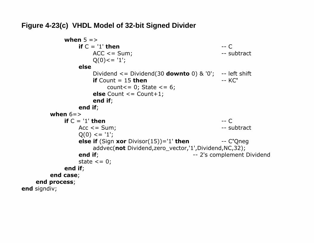
Figure 4-23(c) VHDL Model of 32-bit Signed Divider
when 5 =>if C = '1' then -- C
ACC <= Sum; -- subtractQ(0)<= '1';
elseDividend <= Dividend(30 downto 0) & '0'; -- left shiftif Count = 15 then -- KC'
count<= 0; State <= 6;else Count <= Count+1;end if;
end if;when 6=>
if C = '1' then -- CAcc <= Sum; -- subtractQ(0) <= '1';else if (Sign xor Divisor(15))='1' then -- C'Qneg
addvec(not Dividend,zero_vector,'1',Dividend,NC,32);end if; -- 2's complement Dividendstate <= 0;
end if;end case;
end process;end signdiv;
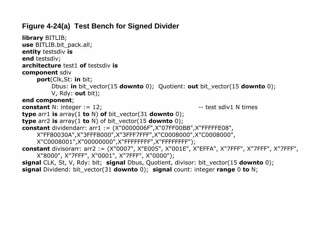
Figure 4-24(a) Test Bench for Signed Dividerlibrary BITLIB;use BITLIB.bit_pack.all;entity testsdiv isend testsdiv;architecture test1 of testsdiv iscomponent sdiv
port(Clk,St: in bit;Dbus: in bit_vector(15 downto 0); Quotient: out bit_vector(15 downto 0);V, Rdy: out bit);
end component;constant N: integer := 12; -- test sdiv1 N timestype arr1 is array(1 to N) of bit_vector(31 downto 0);type arr2 is array(1 to N) of bit_vector(15 downto 0);constant dividendarr: arr1 := (X"0000006F",X"07FF00BB",X"FFFFFE08",
X"FF80030A",X"3FFF8000",X"3FFF7FFF",X"C0008000",X"C0008000",X"C0008001",X"00000000",X"FFFFFFFF",X"FFFFFFFF");
constant divisorarr: arr2 := (X"0007", X"E005", X"001E", X"EFFA", X"7FFF", X"7FFF", X"7FFF",X"8000", X"7FFF", X"0001", X"7FFF", X"0000");
signal CLK, St, V, Rdy: bit; signal Dbus, Quotient, divisor: bit_vector(15 downto 0);signal Dividend: bit_vector(31 downto 0); signal count: integer range 0 to N;
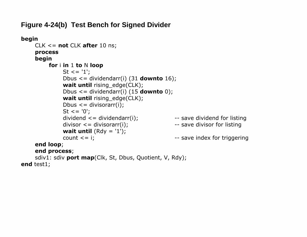
Figure 4-24(b) Test Bench for Signed Divider
beginCLK <= not CLK after 10 ns;processbegin
for i in 1 to N loopSt <= '1';Dbus <= dividendarr(i) (31 downto 16);wait until rising_edge(CLK);Dbus <= dividendarr(i) (15 downto 0);wait until rising_edge(CLK);Dbus <= divisorarr(i);St <= '0';dividend <= dividendarr(i); -- save dividend for listingdivisor <= divisorarr(i); -- save divisor for listingwait until (Rdy = '1');count <= i; -- save index for triggering
end loop;end process;sdiv1: sdiv port map(Clk, St, Dbus, Quotient, V, Rdy);
end test1;
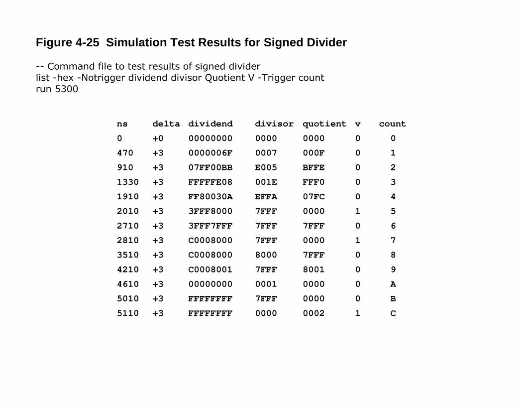
Figure 4-25 Simulation Test Results for Signed Divider
-- Command file to test results of signed dividerlist -hex -Notrigger dividend divisor Quotient V -Trigger countrun 5300
ns delta dividend divisor quotient v count0 +0 00000000 0000 0000 0 0470 +3 0000006F 0007 000F 0 1910 +3 07FF00BB E005 BFFE 0 21330 +3 FFFFFE08 001E FFF0 0 31910 +3 FF80030A EFFA 07FC 0 42010 +3 3FFF8000 7FFF 0000 1 52710 +3 3FFF7FFF 7FFF 7FFF 0 62810 +3 C0008000 7FFF 0000 1 73510 +3 C0008000 8000 7FFF 0 84210 +3 C0008001 7FFF 8001 0 94610 +3 00000000 0001 0000 0 A5010 +3 FFFFFFFF 7FFF 0000 0 B5110 +3 FFFFFFFF 0000 0002 1 C