serial communications primer - alicat scientific · the alicat scientific, inc. serial...
TRANSCRIPT

Serial Communications Primer

DOC-SERIALPRIMER rev 0 Page 2 of 30 September 7, 2018
Introduction The Alicat Scientific, Inc. Serial Communications Primer is intended as a supplement to the introduction to Alicat’s RS-232/RS-485 communication in the product manuals. Its purpose is to provide a clear and concise guide on how Alicat devices bi-directionally communicate over RS-232/RS-485 and how some settings and features can be exploited via terminal programs to enhance the functionality of the device. In an effort to keep this guide concise, the most common features and settings will be discussed.
If your application would benefit from another feature or setting, please contact Alicat Technical Support for assistance.
Alicat Scientific Technical Support [email protected] 1-888-290-6060

DOC-SERIALPRIMER rev 0 Page 3 of 30 September 7, 2018
Contents Introduction .................................................................................................................................................. 2
Unit ID’s, Polling and Streaming ................................................................................................................... 5
Firmware Revisions ....................................................................................................................................... 6
The Alicat Data Frame ................................................................................................................................... 7
Status/Error Codes ........................................................................................................................................ 8
General Query Commands ............................................................................................................................ 8
Device Commands ........................................................................................................................................ 9
Register Basics............................................................................................................................................. 10
What is a Register? ................................................................................................................................. 10
General Notes on Registers .................................................................................................................... 10
Reading a Register Value ........................................................................................................................ 11
Setting/Changing a Register Value .......................................................................................................... 12
Good Practices when Changing Registers ................................................................................................... 12
Setting Registers ......................................................................................................................................... 13
Gas Select (Register 125) ........................................................................................................................ 13
Device Functions (Register 16)................................................................................................................ 13
Power-Up Settings (Register 18) ............................................................................................................. 14
Communication Registers ........................................................................................................................... 16
Device ID and Baud Rate (Register 17) ................................................................................................... 16
Streaming Speed (Register 91) ................................................................................................................ 17
Control and Analog Communication Settings (Register 20) ................................................................... 17
Sensor Registers .......................................................................................................................................... 19
Dead Band / Zero Band (Register 124).................................................................................................... 19
Pressure & Volumetric Flow Averaging (Register 47) ............................................................................. 19
Tare Settings and Special Data Frame Options (Register 19) ................................................................. 20
Control Registers ......................................................................................................................................... 21
PID Loop Select (Register 85) .................................................................................................................. 22
Control Loop Variable Select (Register 122) ........................................................................................... 22
Proportional (P) Control Variable (Register 21) ...................................................................................... 22
Differential (D) Control Variable (Register 22) ........................................................................................ 22
Integral (I) Control Variable (Register 23) .............................................................................................. 22

DOC-SERIALPRIMER rev 0 Page 4 of 30 September 7, 2018
Controller Valve Offset (Register 53) ...................................................................................................... 23
Batch Mode: Controllers with Totalizer Only (Register 92) ................................................................... 23
STP/NTP Registers ....................................................................................................................................... 23
STP Temperature Select (Register 137) .................................................................................................. 24
NTP Temperature Select (Register 139) .................................................................................................. 24
Legacy Registers .......................................................................................................................................... 26
Setpoint: 4v32 and earlier (Register 24) ................................................................................................ 26
Gas Select / Dead Band: GP firmware (Register 46) .............................................................................. 27
Range Dependent STP Select (Register 42) ............................................................................................. 28
STP Display Temperature (Register 93) .................................................................................................. 29
RS-232 / RS-485 Quick Reference Guide ..................................................................................................... 30

DOC-SERIALPRIMER rev 0 Page 5 of 30 September 7, 2018
Unit ID’s, Polling and Streaming Alicat’s RS-232/RS-485 communication structure is a multi-drop interface, where up to 26 different Alicat devices can be communicated over a single COM port (or virtual COM port). Each Alicat device on the multi-drop connection must have a unique single character letter ID using the standard 26 letter English alphabet. No two units can share the same unit ID and still communicate correctly when connected to the same RS-232, RS-485 or USB virtual COM port connection. However, multiple COM port connections can be employed to expand the quantity of units managed by a single computer.
One exception to the standard English character rule is the “@” symbol. An Alicat device set to ID=@ will be in streaming mode. In this state, all data from the device will be delivered to the COM port automatically and repeatedly. This can be very helpful for some resolution sensitive experiments, or to gather as much information as possible over a certain period of time. A device in streaming mode will still be able to receive and understand incoming requests, even though it is sending back continuous data.
Conversely, an Alicat device set to a letter ID is in polling mode, and this is considered the default usage case. In polling mode, a queried instrument will reply with a single data frame for each request received. To query an instrument, type the letter ID into the terminal program followed by a carriage return (<CR>). For example, physically typing A<CR> B<CR> C<CR> in succession, will query devices A, B and C in that order and their respective data frames, beginning with their unit ID, will be received. (Note: A computer can send commands much faster, and without breaks. As such, the commands and responses can get mixed together to form an incomprehensible string of characters. It is usually best to wait for the response to a command before sending the next command.)
Note: When there are multiple units connected to the same COM port, it is required to have all devices set to polling mode. Communication with multiple devices on a single COM port will be disrupted if any of the connected devices are in streaming mode or configured with the same unit ID due to data collision.
If there is a need to send the same command to all connected units at once, the asterisk “*” symbol can be used in place of the unit ID in all commands. This function should be used with caution, as it is possible to negatively alter the configuration or calibration of all connected units at the same time with one command. If a change is accidentally made, Alicat Technical Support can look up the original configuration of the device to assist in reverting the unwanted change.

DOC-SERIALPRIMER rev 0 Page 6 of 30 September 7, 2018
Firmware Revisions As Alicat devices have evolved over the years, so has the firmware. The commands have become shorter and more information is stored in the devices and available for use.
To find out which firmware is installed on your device, check under the device info page on the front screen or use the firmware version query as described in “General Query Commands” later in this manual.
Here is a quick guide to firmware revisions in order of release from oldest to newest.
• GP: All devices with a firmware revision beginning in with “GP” will have a much older circuit board. Devices with this firmware cannot be upgraded past the GP firmware due to hardware incompatibility. GP firmware devices will also require added characters in certain commands.
• 1v-7v: All devices with a firmware revision beginning with “1v”, “2v”, … up to “7v” will have a circuit board newer than GP firmware but older than current mainline. Devices with these firmware revisions and a serial number of less than 135,000 (1v through some 6v) will also have an older processing chip only allowing upgrades up to 6v firmware. Serial numbers above 135,000 can be upgraded to firmware revisions up to 7v. None of these can be “downgraded” to GP firmware due to hardware incompatibility. There were a few features added within these firmware revisions of note:
o Added in 4v25: The ‘Diagnostic Screen’ which will list various information and is useful for troubleshooting over the phone with an applications engineer.
o Added in 4v29: Adjustable STP values. Mass flow controllers with the totalizer installed also have the added benefit of the batch fill feature.
o Added in 5v: More gases to choose from as well as the composer feature for custom gas mixes.
o Added in 6v: User selectable engineering units as well as floating point input of STP values.
o Added in 7v: Reorganized menus on the front screen to be more intuitive. • 8v: All devices with a firmware revision beginning with “8v” or higher will have the
newest circuit board. Devices with this firmware cannot be changed to “7v” or older firmware due to hardware incompatibility.
DOC-SERIALPRIMER rev 0 Page 7 of 30 September 7, 2018
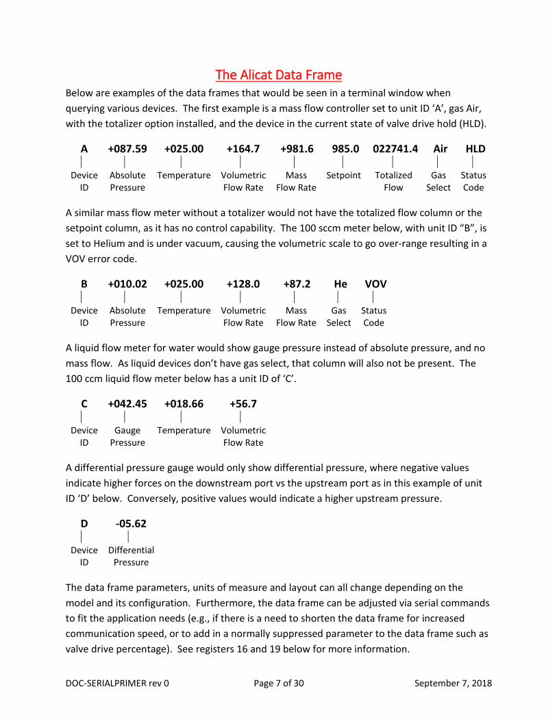
The Alicat Data Frame Below are examples of the data frames that would be seen in a terminal window when querying various devices. The first example is a mass flow controller set to unit ID ‘A’, gas Air, with the totalizer option installed, and the device in the current state of valve drive hold (HLD).
A +087.59 +025.00 +164.7 +981.6 985.0 022741.4 Air HLD
Device ID
Absolute Pressure
Temperature Volumetric Flow Rate
Mass Flow Rate
Setpoint Totalized Flow
Gas Select
Status Code
A similar mass flow meter without a totalizer would not have the totalized flow column or the setpoint column, as it has no control capability. The 100 sccm meter below, with unit ID “B”, is set to Helium and is under vacuum, causing the volumetric scale to go over-range resulting in a VOV error code.
B +010.02 +025.00 +128.0 +87.2 He VOV
Device ID
Absolute Pressure
Temperature Volumetric Flow Rate
Mass Flow Rate
Gas Select
Status Code
A liquid flow meter for water would show gauge pressure instead of absolute pressure, and no mass flow. As liquid devices don’t have gas select, that column will also not be present. The 100 ccm liquid flow meter below has a unit ID of ‘C’.
C +042.45 +018.66 +56.7
Device ID
Gauge Pressure
Temperature Volumetric Flow Rate
A differential pressure gauge would only show differential pressure, where negative values indicate higher forces on the downstream port vs the upstream port as in this example of unit ID ‘D’ below. Conversely, positive values would indicate a higher upstream pressure.
D -05.62
Device ID
Differential Pressure
The data frame parameters, units of measure and layout can all change depending on the model and its configuration. Furthermore, the data frame can be adjusted via serial commands to fit the application needs (e.g., if there is a need to shorten the data frame for increased communication speed, or to add in a normally suppressed parameter to the data frame such as valve drive percentage). See registers 16 and 19 below for more information.
DOC-SERIALPRIMER rev 0 Page 8 of 30 September 7, 2018
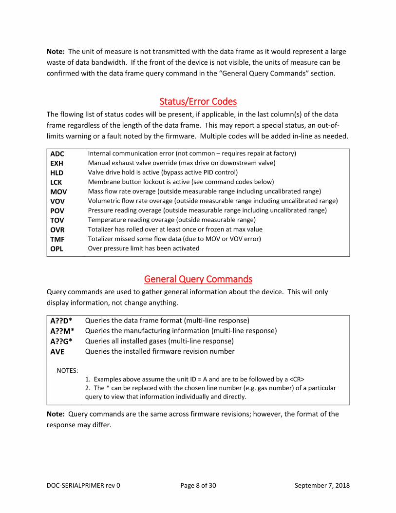
Note: The unit of measure is not transmitted with the data frame as it would represent a large waste of data bandwidth. If the front of the device is not visible, the units of measure can be confirmed with the data frame query command in the “General Query Commands” section.
Status/Error Codes The flowing list of status codes will be present, if applicable, in the last column(s) of the data frame regardless of the length of the data frame. This may report a special status, an out-of-limits warning or a fault noted by the firmware. Multiple codes will be added in-line as needed.
ADC Internal communication error (not common – requires repair at factory) EXH Manual exhaust valve override (max drive on downstream valve) HLD Valve drive hold is active (bypass active PID control) LCK Membrane button lockout is active (see command codes below) MOV Mass flow rate overage (outside measurable range including uncalibrated range) VOV Volumetric flow rate overage (outside measurable range including uncalibrated range) POV Pressure reading overage (outside measurable range including uncalibrated range) TOV Temperature reading overage (outside measurable range) OVR Totalizer has rolled over at least once or frozen at max value TMF Totalizer missed some flow data (due to MOV or VOV error) OPL Over pressure limit has been activated
General Query Commands Query commands are used to gather general information about the device. This will only display information, not change anything.
A??D* Queries the data frame format (multi-line response) A??M* Queries the manufacturing information (multi-line response) A??G* Queries all installed gases (multi-line response) AVE Queries the installed firmware revision number
NOTES: 1. Examples above assume the unit ID = A and are to be followed by a <CR> 2. The * can be replaced with the chosen line number (e.g. gas number) of a particular
query to view that information individually and directly.
Note: Query commands are the same across firmware revisions; however, the format of the response may differ.

DOC-SERIALPRIMER rev 0 Page 9 of 30 September 7, 2018
Device Commands Device Commands are a simplified way of changing various aspects of an Alicat device. A device command will automatically change the associated register value(s) as necessary. It is often easier to use a device command than to change a register directly.
Some commands are universal between all models, others are specific to a particular type of instrument. For example, a mass flow meter will not respond to a new setpoint command, as it has no attached valve to control. Similarly, a pressure gauge will ignore a volumetric flow tare command as it does not measure flow rate. As device commands have been added throughout the years, not all of the commands below are available on older firmware revisions.
A Query/Poll a single data frame A@=B Set unit ‘A’ to have the new unit ID of ‘B’ A@=@ Set unit ‘A’ to data streaming mode *@=A Set the streaming device back to polling mode with the unit ID ‘A’ AR[#] Read contents of register number [#] AW[#]=[x] Write a new value [x] to register number [#] A[x] Send a new setpoint in counts as defined by register 24 AS[x.x] Send a new setpoint value [floating point value in selected engineering units] AG[x] Change gas type (by assigned number) AV Volumetric flow tare (subsequently tares mass flow as well, if applicable) AP Pressure tare (gauge and differential pressure units only) APC Absolute pressure tare against internal barometer (if installed) AT Reset totalizer (if installed) AH Same as AHP (for single valve controllers) or AHC (for dual valve controllers) AHC Hold valve(s) closed AHP Hold valve(s) at current position AE Exhaust valve open, inlet valve closed (dual valve controllers only) AC Continue close loop control (cancel any hold conditions) AL Lock display buttons (ignores button presses only if they would cause a change) AU Unlock display buttons AOPL[x.x] Set upper pressure limit [floating point value in selected engineering units]
NOTES: 1. Examples above assume unit ID = A and are to be followed with <CR> 2. [#] represents a register number 3. [x] represents an integer value
Note: All devices with GP firmware will require ‘$$’ to be added after the unit ID in each of the above commands. Example: A$$R[#]
DOC-SERIALPRIMER rev 0 Page 10 of 30 September 7, 2018
Register Basics All Alicat instruments have their configuration settings, custom options and calibration values stored within digital registers. While similar in concept, the type of data stored in an Alicat register and the methods of reading/writing Alicat registers are generally different from those mandated in modern day industrial protocols.
What is a Register? At the most basic level, a register is just a memory location that contains a value. Alicat devices have dozens of registers that contain numeric values with each register having a unique numeric address used to distinguish one location from another. With the exception of one register that contains a floating point value, Alicat registers are stored as 8, 16 or 32 bit integers.
Most Alicat registers contain values for configuring the device, but some hold calibration information, sensor values or other run time data. Live data registers, like the raw sensor values, are read-only; while most other register values can be over-written.
Alicat device registers are usually accessed through commands issued over a serial port. Alternatively, some registers may be viewed on the front display in the ‘Device State’ or ‘Diag’ menus. This display can be an extremely helpful tool for troubleshooting sensor health and device configuration while talking with Alicat technical support. Devices with firmware 8v or newer also allow some register changes via the front panel.
General Notes on Registers Because particular types of Alicat instruments assign a different meaning to the value in each register, it is not a simple process to determine the full meaning of each register for every device built. This guide will explain the most commonly used registers.
If a specific change is not listed in this document, it may still be possible. Please contact Alicat Technical Support for assistance.
A few more items to note:
• Changing register values will alter (and done incorrectly, can impair) the operation of your device. Please consult the factory if you have any questions about a particular register’s function and how it may impact your device.
• Alicat devices built after 2008 are case insensitive. Older devices will require capital letters for all commands. All commands in this guide will be capitalized for convenience.
• Any adjustment of the associated calibration registers will invalidate the most recent NIST traceable calibration certificate that was provided by Alicat Scientific Inc.

DOC-SERIALPRIMER rev 0 Page 11 of 30 September 7, 2018
As such, they will not be included in this document. For assistance on using your own calibration standards to recalibrate your device, please contact Alicat Technical Support.
• Due to system constraints, a single register can be coded to store multiple functionality/configuration settings. In the cases of multi-function registers, it is required to sum multiple bits to obtain the desired functional result.
• Should an accidental register change occur, don’t panic. Alicat maintains a complete database of all devices’ register values as they left the factory. Newer devices will also have a factory reset option on the front panel to restore the device back to its original shipped state.
Reading a Register Value The format for issuing a command over the serial port to read a particular register is below, called the ‘Read’ command:
deviceID R address <CR>
where deviceID is the unit ID letter of the device you would like to query, and the address is the register number that you would like to know the value of.
Example: To read register 16 from unit ID ‘B’, type the command:
BR16<CR>
When this command is received, the device will look up the location for the given address and return the value found there in the following form:
deviceID address = valueInRegister
The data returned in the terminal window would look something like this:
B 016 = 199
Note: On devices with GP firmware, if the user requests the value of a register that does not exist, the device will respond with a ‘?’. For firmware revisions 1v-4v, it will respond with a value of 4; and for 5v and newer, a value of 1.

DOC-SERIALPRIMER rev 0 Page 12 of 30 September 7, 2018
Setting/Changing a Register Value The format for issuing a command over the serial port to change a particular register is below, called the ‘Write’ command:
deviceID W address = desiredValue
Example: To change register 12 to the value of 100 on unit ‘G’, type the command:
GW12=100<CR>
When this command is received, the device will set the value in the register (if possible) and respond with the updated value, in the same format as reading a register:
deviceID address = valueInRegister
The new setting is confirmed in the terminal window, and would look something like this:
G 012 = 100
If a register cannot be written to, the value in the register is not changed, and the unchanged value is returned. There will be no error indication.
Good Practices when Changing Registers Below is a list of commonly used registers that apply to most Alicat flow and pressure devices. The format of the descriptions will differ with the different type of registers. The most noted being the multi-purpose registers that change more than one feature/configuration and require a more complex set of tables.
For ease, registers are grouped by function rather than number.
When adjusting any register, it is recommended to use the following methodology:
1. Read the value in the register. 2. Record the current value for reference. 3. Determine the needed change by consulting the list below. 4. Record the new value for reference. 5. Write the new value into the register.

DOC-SERIALPRIMER rev 0 Page 13 of 30 September 7, 2018
Setting Registers
Gas Select (Register 125) This register governs the gas selection and was added in the 5v09 firmware revision. While the gas number assignments have not changed over the years, the number of gases available has increased. As such, all currently available gases may not be available on older devices. Furthermore, corrosive gases are not available on devices that are incompatible with them. It is completely normal for a standard series meter to have all pure corrosive and refrigerant gases missing from the gas select menu. To acquire the list of gases available on a specific device, please use the query gas table command from the “General Query Commands” section. For convenience, the first few gases are listed below.
Sample of Gas Table 0 = Air 6 = H2 (Hydrogen) 1 = Ar (Argon) 7 = He (Helium) 2 = CH4 (Methane) 8 = N2 (Nitrogen) 3 = CO (Carbon Monoxide) 9 = N2O (Nitrous Oxide) 4 = CO2 (Carbon Dioxide) 10 = Ne (Neon) 5 = C2H6 (Ethane) 11 = O2 (Oxygen) NOTE: For pressure units (which don’t require gas properties), any value may be used.
Example: Suppose there is an MFC currently set to Argon that needs to be changed to Hydrogen. Change the value in this register from 1 to 6.
Device Functions (Register 16) This register is a three-part configuration setting which determines which core functions are enabled on the device, what parameters are hidden from the front screen / data frame and whether the analog in/out signals are inverted in their operation.
The first part of the register (bits 256, 512, 1024, 16384, 32768) determine which parameters will be hidden in the data frame as well as the front screen. This will allow trimming down (and speeding up!) of the data frame, or simply hiding unwanted data from view. Choose any, all or none from the first table.
The second part of the register contains the critical bits (1, 2, 4, 32, 64, 128) which configure all of the measurement/processing functions a particular instrument has available for internal use. These should never be changed in the field as all devices will be configured with the proper functions enabled. It is only included for completeness.
DOC-SERIALPRIMER rev 0 Page 14 of 30 September 7, 2018
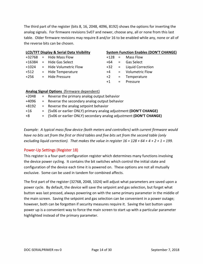
The third part of the register (bits 8, 16, 2048, 4096, 8192) shows the options for inverting the analog signals. For firmware revisions 5v07 and newer, choose any, all or none from this last table. Older firmware revisions may require 8 and/or 16 to be enabled while any, none or all of the reverse bits can be chosen.
LCD/TFT Display & Serial Data Visibility System Function Enables (DON’T CHANGE) +32768 = Hide Mass Flow +128 = Mass Flow +16384 = Hide Gas Select +64 = Gas Select +1024 = Hide Volumetric Flow +32 = Liquid Correction +512 = Hide Temperature +4 = Volumetric Flow +256 = Hide Pressure +2 = Temperature +1 = Pressure Analog Signal Options (firmware dependent) +2048 = Reverse the primary analog output behavior +4096 = Reverse the secondary analog output behavior +8192 = Reverse the analog setpoint behavior +16 = (5v06 or earlier ONLY) primary analog adjustment (DON’T CHANGE) +8 = (5v06 or earlier ONLY) secondary analog adjustment (DON’T CHANGE)
Example: A typical mass flow device (both meters and controllers) with current firmware would have no bits set from the first or third tables and five bits set from the second table (only excluding liquid correction). That makes the value in register 16 = 128 + 64 + 4 + 2 + 1 = 199.
Power-Up Settings (Register 18) This register is a four-part configuration register which determines many functions involving the device power cycling. It contains the bit switches which control the initial state and configuration of the device each time it is powered on. These options are not all mutually exclusive. Some can be used in tandem for combined affects.
The first part of the register (32768, 2048, 1024) will adjust what parameters are saved upon a power cycle. By default, the device will save the setpoint and gas selection, but forget what button was last pressed, always powering on with the same primary parameter in the middle of the main screen. Saving the setpoint and gas selection can be convenient in a power outage; however, both can be forgotten if security measures require it. Saving the last button upon power up is a convenient way to force the main screen to start up with a particular parameter highlighted instead of the primary parameter.
DOC-SERIALPRIMER rev 0 Page 15 of 30 September 7, 2018
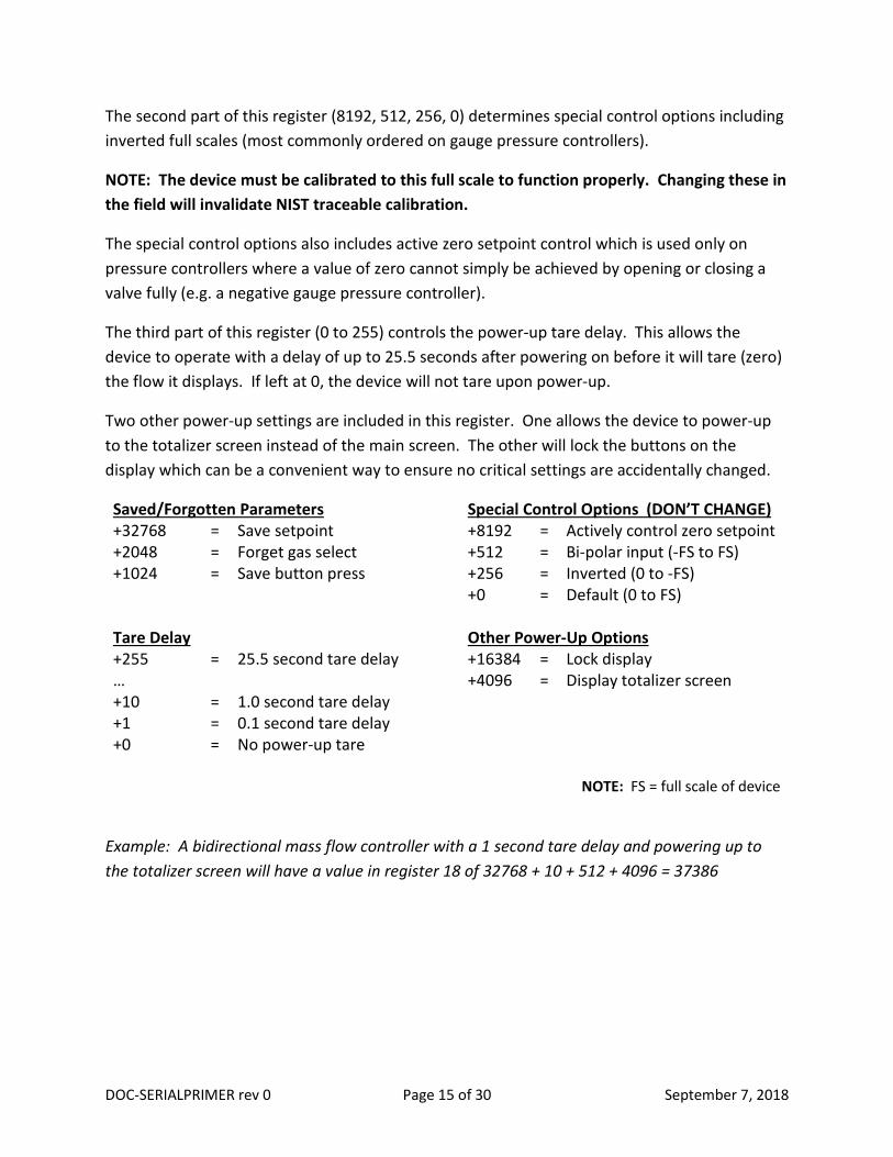
The second part of this register (8192, 512, 256, 0) determines special control options including inverted full scales (most commonly ordered on gauge pressure controllers).
NOTE: The device must be calibrated to this full scale to function properly. Changing these in the field will invalidate NIST traceable calibration.
The special control options also includes active zero setpoint control which is used only on pressure controllers where a value of zero cannot simply be achieved by opening or closing a valve fully (e.g. a negative gauge pressure controller).
The third part of this register (0 to 255) controls the power-up tare delay. This allows the device to operate with a delay of up to 25.5 seconds after powering on before it will tare (zero) the flow it displays. If left at 0, the device will not tare upon power-up.
Two other power-up settings are included in this register. One allows the device to power-up to the totalizer screen instead of the main screen. The other will lock the buttons on the display which can be a convenient way to ensure no critical settings are accidentally changed.
Saved/Forgotten Parameters Special Control Options (DON’T CHANGE) +32768 = Save setpoint +8192 = Actively control zero setpoint +2048 = Forget gas select +512 = Bi-polar input (-FS to FS) +1024 = Save button press +256 = Inverted (0 to -FS) +0 = Default (0 to FS) Tare Delay Other Power-Up Options +255 = 25.5 second tare delay +16384 = Lock display … +4096 = Display totalizer screen +10 = 1.0 second tare delay +1 = 0.1 second tare delay +0 = No power-up tare
NOTE: FS = full scale of device
Example: A bidirectional mass flow controller with a 1 second tare delay and powering up to the totalizer screen will have a value in register 18 of 32768 + 10 + 512 + 4096 = 37386

DOC-SERIALPRIMER rev 0 Page 16 of 30 September 7, 2018
Communication Registers
Device ID and Baud Rate (Register 17) This register is a two-part configuration setting that governs the device’s communication baud rate and unit ID. By default, all Alicat devices are shipped with a baud rate of 19,200 and unit ID of ‘A’. Recall there is a device command to change the unit ID that is simpler, and both unit ID and baud rate can be changed via the front panel.
The first part of this register determines the unit ID with the higher level of bits ranging from 16384 to 23040 in steps of 256. This can be thought of as the ASCII character value multiplied by 256, where ASCII is ‘A’=65, ‘B’=66, … , ‘Z’=90. For example, ‘A’=65*256=16640.
The second part of this register determines the baud rate which allows the user to speed up or slow down the baud rate of the device in order to match a specific serial port data rate.
Note: Once the baud rate is changed, communication will be lost until the serial port baud rate changes to match (often requiring restarting the communication program). For baud rates higher than 38400, register 87 must also have 2 added to it.
Unit ID Baud Rate +16384 = @ (streaming mode) +245 = 115,200 (requires +2 in register 87) +16640 = A +244 = 57,600 (requires +2 in register 87) +16896 = B +243 = 38,400 … = +242 = 19,200 +23040 = Z +241 = 9,600 +240 = 2,400
Example: Suppose a new Alicat device was shipped with the standard Unit ID of ‘A’ and baud rate 19,200. To change that device to have unit ID ‘G’ and a baud rate of 9,600, the new value in register 17 would need to be 18176 + 241 = 18417.

DOC-SERIALPRIMER rev 0 Page 17 of 30 September 7, 2018
Streaming Speed (Register 91) This register governs the speed at which the device will send a data frame over the serial port when in streaming mode (unit ID=@). When the streaming speed is set particularly fast, the communication will become limited by the data frame size and the baud rate. See registers 16, 17 and 19 to adjust the data frame size and baud rate.
Register values correspond directly to the time in ms between beginning to send a data frame and beginning to send the next data frame.
Value Time +1 = 1 ms +2 = 2 ms … … +50 = 50 ms (Default) … … +65535 = 65.535 seconds
Control and Analog Communication Settings (Register 20) Register 20 is considered one of the primary configuration registers for any Alicat device, and therefore should be treated with special care. This register manages a wide range of higher level features, such as control logic options, parameter under control and the analog signals. As with other configuration registers, related changes made via the front panel buttons will sync and update this register accordingly and vice versa.
The Controller Options table specifies choices for the setpoint input method, control logic and auto-tare configuration. There are four options for setpoint input method: analog-voltage, analog-current, digital and local. On newer devices, local and digital are the same selection.
Note: Physical changes are required in conjunction with these register settings to change the type of analog setpoint, which will not be detailed in this guide (e.g. changing to or from a 4-20mA setpoint input method).
There are two options for control logic: normal and inverted. Normal control logic will open the valve further to increase flow (or pressure) and close it further to decrease. Inverse control mode is used almost exclusively for back pressure controllers where the valve must open further to vent pressure and close further to increase pressure.
There are two options for auto-tare: enabled and disabled. This is not the same as power-up tare and is only available on controllers. When enabled, auto-tare will zero the flow (or pressure) after it is given a setpoint of 0 for more than the auto-tare delay written in register 19. As pure vacuum is nearly impossible to achieve, auto-tare should not be enabled on absolute pressure controllers.

DOC-SERIALPRIMER rev 0 Page 18 of 30 September 7, 2018
The Control Parameter Select table governs which measurement parameter a given controller will attempt to control when given a setpoint, also called the closed loop variable. Changing this variable from flow to pressure, or vice versa, may require significantly different PID values for the valve tuning.
Note: For controllers with a barometer installed, please see register 122 for further instructions.
The Analog Output Signal table governs the type of analog outputs the device is configured for. These should never be changed in the field as hardware changes are required. The Analog Output Variable table governs which variable will output on the selected analog output.
Note: A device with a static 5.12 Vdc secondary output cannot be changed to a variable based secondary output without hardware changes.
Controller Options (choose any, all or none) Else +32768 = Inverted control logic Normal control logic +16384 = Analog setpoint (voltage or current) Digital/local setpoint +8192 = Auto-tare enabled (default) Auto-tare disabled +4096 = 4-20mA setpoint (DON’T CHANGE) Voltage setpoint (if analog) +2048 = Local setpoint (5v or earlier only) Analog or Digital
Control Parameter Select (choose only 1) +1024 = Mass flow control +768 = Volumetric flow control +256 = Pressure control +0 = No control capability
Analog Output Signal (one primary and one secondary selected) Primary (hardware dependent) Secondary (hardware dependent) +4 = 0-5Vdc, 0-10Vdc OR 4-20mA +64 = 0-5Vdc, 0-10Vdc OR 4-20mA +8 = 1-5Vdc +128 = 1-5Vdc +12 = 0-5Vdc bidirectional +192 = 0-5Vdc bidirectional +16 = Static 5.12Vdc (default) Analog Output Variable (choose one primary and one secondary) Primary Secondary +3 = Mass Flow +48 = Mass Flow +2 = Volumetric Flow +32 = Volumetric Flow +1 = Temperature +16 = Temperature +0 = Pressure +0 = Pressure
DOC-SERIALPRIMER rev 0 Page 19 of 30 September 7, 2018
Example: A mass flow controller set to control mass flow via its 4-20 mA input, with a 4-20 mA primary output of volumetric flow and a static secondary output will have auto-tare enabled by default. The associated value in register 20 would be 16384 (analog setpoint) + 8192 (auto-tare enabled) + 4096 (4-20 mA setpoint) + 1024 (mass flow control) + 4 (4-20 mA primary output) + 16 (static 5.12 Vdc secondary output) + 2 (volumetric flow output) = 27918.
Sensor Registers
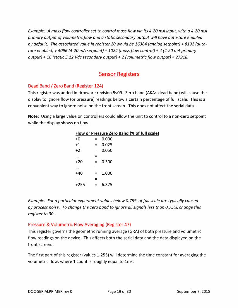
Dead Band / Zero Band (Register 124) This register was added in firmware revision 5v09. Zero band (AKA: dead band) will cause the display to ignore flow (or pressure) readings below a certain percentage of full scale. This is a convenient way to ignore noise on the front screen. This does not affect the serial data.
Note: Using a large value on controllers could allow the unit to control to a non-zero setpoint while the display shows no flow.
Flow or Pressure Zero Band (% of full scale) +0 = 0.000 +1 = 0.025 +2 = 0.050 … = +20 = 0.500 … = +40 = 1.000 … = +255 = 6.375
Example: For a particular experiment values below 0.75% of full scale are typically caused by process noise. To change the zero band to ignore all signals less than 0.75%, change this register to 30.
Pressure & Volumetric Flow Averaging (Register 47) This register governs the geometric running average (GRA) of both pressure and volumetric flow readings on the device. This affects both the serial data and the data displayed on the front screen.
The first part of this register (values 1-255) will determine the time constant for averaging the volumetric flow, where 1 count is roughly equal to 1ms.

DOC-SERIALPRIMER rev 0 Page 20 of 30 September 7, 2018
The second part of this register will determine the time constant for averaging pressure. Pressure should almost always be set to minimum averaging (256).
Pick one from the first two columns and add to get the value required in this register.
Flow Pressure GRA (roughly the time constant in ms) 1 256 = 1 2 512 = 2 … … … … 255 65280 = 255
Examples: Typical values that are used include 257 (minimum averaging), 383 (50% average on volumetric flow) and 511 (100% averaging on volumetric flow). 100% averaging corresponds a time constant of approximately 255ms.
Tare Settings and Special Data Frame Options (Register 19) This register is a four-part register, determining the various tare options. These settings range from enabling a tare button on the display to setting the automatic tare delay length discussed in register 20.
The Display Tare Type table shows the bits needed to enable the tare button on the main screen and determine which variable will be zeroed when the button is pressed. By default, all meters have the tare button enabled and set to tare the primary variable.
The Remote Tare Select table allows a flow meter or pressure gauge (no controllers!) to be given a ‘short to ground’ signal via a setpoint pin. This is an alternate way to electromechanically tare a chosen variable from the list by grounding a pin. If no value is selected, the remote tare will be disabled. By default, this will be enabled and set to tare the primary variable.
The Auto-Tare Delay table configures the delay period before automatic taring occurs (see register 20 for more information). By default, this delay is set to 1.1 seconds after the device is given a zero setpoint, except in the case of very low flow controllers (50 sccm or less). In those cases, using a longer auto-tare delay will allow the slower changing internal gas pressures to equalize, and flow to truly stop, before a zeroing occurs.
The Special Data Frame Options table shows more options (in addition to register 16) for what is shown in the serial data frame. The valve drive percentage option is only available on controllers.

DOC-SERIALPRIMER rev 0 Page 21 of 30 September 7, 2018
Choose only one element from each of the first three sections.
Main Screen Tare Type Remote Tare Select Auto-Tare Delay +8192 = Flow +768 = Totalizer +255 = 25.5 second +4096 = Pressure +512 = Flow … +0 = None +256 = Pressure +10 = 1.0 second +0 = None +1 = 0.1 second +0 = 0 second Special Data Frame Options (choose any, all or none) +1024 = Hide totalizer from data frame (firmware revision 5v05 or higher) +2048 = Display totalizer peak in the data frame (firmware version 5v07 or higher) +16384 = Display the totalizer timer in the data frame (firmware version 4v33 or higher) +32768 = Display valve drive % in the data frame (firmware version GP07R86 or higher)
Example: A differential pressure gauge will have only the display and remote tare available for pressure, and the value in register 19 would be 4096 + 256 = 4352.
Control Registers Alicat controllers use a closed loop control algorithm which uses the error between the setpoint and the measured value to make adjustments to the valve drive to minimize that error. Alicat uses two different types of closed loop algorithms that govern the way the valve will open or close in response to flow: PD and PD2I. Single valve pressure units and all mass flow units can switch between the two algorithms while PCD-series should always be set to PD2I. Some older devices will have a PDF algorithm in place of the PD algorithm or even an added PDI algorithm. PD, PDF and PDI are marginally different in performance; however, the values for P, I and D can vary significantly between them.
Due to the scope of this document, PID tuning methodology will not be covered. Please reference the product manual or visit www.alicat.com/pid or www.alicat.com/pd2i for tuning assistance. Alicat PID tuning differs slightly from standard PID tuning, and it is useful for those familiar with standard PID tuning to familiarize themselves with the Alicat method.
Independent of tuning algorithm, the valve offset can be adjusted to improve performance. In most cases, this can be kept at factory default.
The values for P, I, D and valve offset vary across the age of the device, firmware revision, valve type and can even vary slightly due to manufacturing differences in the valves. As such, there is no “default” value listed for any of these registers.

DOC-SERIALPRIMER rev 0 Page 22 of 30 September 7, 2018
PID Loop Select (Register 85) This register determines if PD or PD2I is used and was added in 1v firmware. In most single valve devices, PD will be selected and almost all dual valve devices should have PD2I selected. Note that MCH or PCH devices with two valves in parallel work as a “single valve” device. The term “dual valve” refers only to bidirectional devices such as the PCD or MCD series.
This register differs slightly over firmware revisions for dual valve controllers.
Value Type Firmware Restriction +32768 = Dual valve +2 = PD2I +1 = PD +0 = PDI 4v29 and earlier
Note: For firmware 5v06 through 7v0 +32768 should be used only for PCDs while +16384 should be used only for MCDs. Register 122 will not be used.
Control Loop Variable Select (Register 122) This is primarily for use with mass flow controllers equipped with an internal barometer or dual valve controllers and was added in firmware revision 6v0. Register 20 will over-ride this register and vice versa.
Value Control Loop 0 or 1 = Disabled 34 = Absolute Pressure 36 = Volumetric Flow 37 = Mass Flow 38 = Gauge Pressure 39 = Differential Pressure
Proportional (P) Control Variable (Register 21) This register can be any whole number between 1 and 65535. It is the same number as the P value displayed on the front screen.
Differential (D) Control Variable (Register 22) This register can be any whole number between 1 and 65535. It is the same number as the D value displayed on the front screen.
Integral (I) Control Variable (Register 23) This register can be any whole number between 1 and 65535. It is the same number as the I value displayed on the front screen.

DOC-SERIALPRIMER rev 0 Page 23 of 30 September 7, 2018
For firmware revisions 1v and later, the I value will only be used when the controller is in PD2I mode or PDI mode.
On devices with GP firmware, this register also controls the PID loop select. If I is even, the PD control loop algorithm will be used. If I is odd, the PD2I will be used instead.
Controller Valve Offset (Register 53) This register controls the amount of valve drive power applied to a closed valve, affecting the point at which the valve opens. Valid values range from 0 and 65535 with 0 being 0 valve drive and 65535 being maximum.
Typically this register will be changed prior to PID and only changed if there are control issues with small setpoints.
To change the valve offset the following is recommended for all flow controllers and single-valve forward pressure controllers (For back pressure regulators and PCD-series devices, please contact Alicat Technical Support for instructions.):
1. Place the device in typical operating conditions, and ensure it has a zero setpoint. 2. Change the setpoint to about 1-2% of full scale. Observe the device and see how long it
takes to register a reading. 3. If the timing is longer than desired, increase this register value by 1000. If the device is
overshooting the setpoint more than desired, decrease the register value by 1000. 4. Repeat as necessary.
Batch Mode: Controllers with Totalizer Only (Register 92) This register will only impact mass flow controllers with a totalizer and firmware 4v29 or later. This register is the only floating point register. Put the batch value for the totalizer in the selected totalizer engineering units into the register to give the batch. If this register is set to 0, the batch feature will be disabled, and it the device will control to the current setpoint regardless of the totalizer value.
Example: Suppose a controller has a totalizer set in scc, and a batch volume of 50.5 scc is desired. Write 50.5 to this register to achieve a batch of 50.5 scc.
STP/NTP Registers STP and NTP selections have significantly changed in different firmware revisions as more functionality has been added. Please pay careful attention as to which registers require changing for a particular firmware. To avoid confusion, legacy STP/NTP registers are referenced in this section and described in the Legacy Registers section later in this guide.

DOC-SERIALPRIMER rev 0 Page 24 of 30 September 7, 2018
Firmware Notes:
• 4v28 and earlier: Register 42 is the only register required to change. • 4v29 through 5v: Register 42 will change the calculated mass flow based on the
selected STP ONLY. It will not update the selected STP on the front panel. It is highly recommended to also change register 93 to update the displayed STP to avoid confusion. NOTE: Changing the STP via the front panel after changing register 42 and NOT changing register 93 will cause the mass flow to be calculated incorrectly.
• 6v and later: Registers 42 & 93 can typically be ignored, as either register 137 OR 139 can be used to change both the mass flow calculation and the display in a single register. If the device was shipped with the default STP of 25°C and 1 atm. It is NOT recommended to change registers 42 or 93.
As the standard pressure is almost always 1 atmosphere, this guide will focus only on how to change the standard (or normal) temperature.
STP Temperature Select (Register 137) NOTES:
1. This register is only available on firmware revisions 6v and later. 2. This register will change the standard temperature ONLY. It will not change the normal
temperature. As such, it will only affect mass flow calculations when the engineering unit begins with “S”.
This register is dictated by a single mathematical function.
Value = (STP temperature in Kelvin) x 100,000
Value Temperature 29815000 = 25°C 29426000 = 70°F (21.11°C) 29415000 = 21°C 29315000 = 20°C 27315000 = 0°C
Example: Suppose a device needs a standard temperature of 20°C. 20°C = 293.15 K. Multiply by 100,000 to get 293150000. Change the value in register 93 to 29315000 to show a selection of 20°C on the front screen.
NTP Temperature Select (Register 139) NOTES:

DOC-SERIALPRIMER rev 0 Page 25 of 30 September 7, 2018
1. This register is only available on firmware revisions 6v and later. 2. This register will change the normal temperature ONLY. It will not change the standard
temperature. As such, it will only affect mass flow calculations when the engineering unit begins with “N”.
This register uses the same function as register 137 to calculate the needed value. Refer to register 137 above for equation and example table.

DOC-SERIALPRIMER rev 0 Page 26 of 30 September 7, 2018
Legacy Registers These registers are intended for use with older firmware revisions. While they will function with newer firmware, new commands or registers have been created for simplicity and ease of use.
Setpoint: 4v32 and earlier (Register 24) For newer firmware, use the setpoint command AS[x.x] as listed in the “Device Commands” section.
This register governs the setpoint of a controller. It is an alternative to the setpoint commands listed in the “Device Commands” section and is generally unnecessarily complex. This is not a direct correlation of how far the valve will open. The setpoint is instead given in percentage of the full scale of the device. It is included here for completeness and backwards compatibility.
Value % Full Scale Uni-directional Bi-directional +80000 = 125 150 +64000 = 100 100 +48000 = 75 50 +32000 = 50 0 +16000 = 25 -50 +0 = 0 -100
NOTE:
1. “GP” firmware devices will only go up to 65535 or 102.4% of full scale. 2. New firmware will only go up to 125% of full scale for bi-directional devices. 3. While setpoints greater than 100% are possible, devices are never calibrated above
100% of full scale. All readings above 100% are based on interpolation and stable control may not be possible for setpoints greater than 100%.
4. This register is ignored or overwritten when an analog setpoint is accepted.
Example: To give a setpoint of 80% of full scale on a uni-directional device, set register 24 to 64000 x 0.8 = 51200.
DOC-SERIALPRIMER rev 0 Page 27 of 30 September 7, 2018
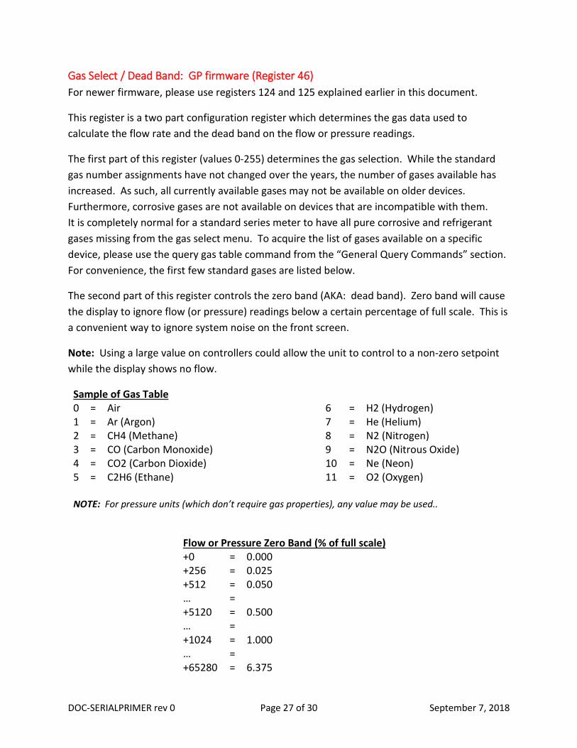
Gas Select / Dead Band: GP firmware (Register 46) For newer firmware, please use registers 124 and 125 explained earlier in this document.
This register is a two part configuration register which determines the gas data used to calculate the flow rate and the dead band on the flow or pressure readings.
The first part of this register (values 0-255) determines the gas selection. While the standard gas number assignments have not changed over the years, the number of gases available has increased. As such, all currently available gases may not be available on older devices. Furthermore, corrosive gases are not available on devices that are incompatible with them. It is completely normal for a standard series meter to have all pure corrosive and refrigerant gases missing from the gas select menu. To acquire the list of gases available on a specific device, please use the query gas table command from the “General Query Commands” section. For convenience, the first few standard gases are listed below.
The second part of this register controls the zero band (AKA: dead band). Zero band will cause the display to ignore flow (or pressure) readings below a certain percentage of full scale. This is a convenient way to ignore system noise on the front screen.
Note: Using a large value on controllers could allow the unit to control to a non-zero setpoint while the display shows no flow.
Sample of Gas Table 0 = Air 6 = H2 (Hydrogen) 1 = Ar (Argon) 7 = He (Helium) 2 = CH4 (Methane) 8 = N2 (Nitrogen) 3 = CO (Carbon Monoxide) 9 = N2O (Nitrous Oxide) 4 = CO2 (Carbon Dioxide) 10 = Ne (Neon) 5 = C2H6 (Ethane) 11 = O2 (Oxygen) NOTE: For pressure units (which don’t require gas properties), any value may be used..
Flow or Pressure Zero Band (% of full scale) +0 = 0.000 +256 = 0.025 +512 = 0.050 … = +5120 = 0.500 … = +1024 = 1.000 … = +65280 = 6.375

DOC-SERIALPRIMER rev 0 Page 28 of 30 September 7, 2018
Example: Suppose there is a mass flow meter that needs to be set to Helium with a dead band of 0.25% of full scale. Helium has a gas number of 7, and 0.25% of full scale would have a bit value of 2560. Thus, this register should be re-written to 7 + 2560 = 2567.
Range Dependent STP Select (Register 42) NOTES:
1. Recommended for use with 5v firmware and earlier only. 2. Remember to change register 93 as well for firmware 4v29 and later. 3. The following instructions are ONLY applicable for mass flow devices where the
volumetric flow and mass flow full scale ranges are equal. If your device has a volumetric flow range that is different from the mass flow range, please contact Alicat technical support for instructions.
4. The following instructions are ONLY applicable for standard and whisper mass flow devices with the default pressure range (160 PSIA and 60 PSIA respectively). For high pressure Q-series and devices with custom pressure ranges, please contact Alicat technical support for instructions.
This register will work slightly different for standard and whisper devices as their full scale pressure differs.
To change the standard temperature on a standard mass flow device, multiply 32768 by the ratio of the desired temperature in Kelvin to 298.15 K (25°C). To change the standard temperature on a whisper mass flow device, multiply 12288 by the ratio of the desired temperature in Kelvin to 298.15 K (25°C).
Example: To change a standard mass flow device to 0°C, first translate 0°C into Kelvin: 0 + 273.15 = 273.15 K. Then, take the ratio of this with 298.15 K: 273.15 K / 298.15 K = 0.916149589. Multiply the result by 32768 to get 0.916149589 x 32768 = 30020.3897. As this register can only accept whole numbers, round to 30020. Changing register 42 to 30020 will select an STP of 0°C and 1 atm.
Common STP with standard pressure of 1 atm Standard Series Whisper Series Value Temperature Value Temperature 32768 = 25°C 12288 = 25°C 32340 = 70°F (21.11°C) 12128 = 70°F (21.11°C) 32328 = 21°C 12123 = 21°C 32218 = 20°C 12082 = 20°C 30020 = 0°C 11258 = 0°C

DOC-SERIALPRIMER rev 0 Page 29 of 30 September 7, 2018
STP Display Temperature (Register 93) NOTES:
1. This register does not exist in firmware revisions 4v28 and earlier 2. This register should ALWAYS be changed whenever a change is made in register 42
and the device has a front screen. 3. This register should NEVER be changed without also updating register 42. 4. This register does NOT work the same after 6v0. Please contact Alicat Technical Support
for assistance.
This register is dictated by a single mathematical function.
Value = (STP temperature in Kelvin) x 100,000
Example: Suppose a device needs a standard temperature of 20°C. 20°C = 293.15 K. Multiply by 100,000 to get 293150000. Change the value in register 93 to 29315000 to show a selection of 20°C on the front screen.
Value Temperature 29815000 = 25°C 29426000 = 70°F (21.11°C) 29415000 = 21°C 29315000 = 20°C 27315000 = 0°C

DOC-SERIALPRIMER rev 0 Page 30 of 30 September 7, 2018
RS-232 / RS-485 Quick Reference Guide
Below is an example of the data line that will be returned from a device being communicated with through RS-232 / RS-485, and an explanation of what each output means.
A +087.59 +025.00 +164.7 +981.6 985.0 022741.4 Air HLD
Device ID
Absolute Pressure
Temperature Volumetric Flow Rate
Mass Flow Rate
Setpoint Totalized Flow
Gas Select
Status Code
Note: For devices with software versions starting with “GP” (generally serial numbers lower than 80,000), two “$” characters need to be added after the unit ID in the commands indicated below. Example: A$$V
Status Codes ADC – Analog to Digital Conversion error EXH – Exhaust mode active HLD – Valve HOLD active LCK – Display LOCK active MOV – Mass flow Overage OPL – Over Pressure Limit OVR – Totalizer Overage POV – Pressure Overage TOV – Temperature Overage TMF – Totalizer Missed Flow due to overage VOV – Volumetric flow Overage
Commands General *@=@ – Sets device to streaming mode *@=A – Sets device Unit ID to “A” A – Returns data frame
Setpoint A[#] – Sends new setpoint (in counts with 64000 = full scale) AS[#] – Sends a new setpoint (in units selected on device)
Gas AG[#] – Changes gas selection
Tare AV – Flow Tare (Volumetric and Mass, when available) AP – Gauge Pressure Tare (when available) APC – Absolute Pressure Tare (when available)
Totalizer AT – Resets Totalizer
Valves AH – Holds valve at present value (closes both valves on dual valve) AHC – Holds all valves closed AHP – Holds valves at present value (single and dual valves) AE – Exhausts valve open, inlet valve closed AC – Cancels valve hold
Display AL – Locks display AU – Unlocks display
Registers AR[#] – Reads contents of register AW[#]=[value] – Writes value to register
Other AOPL[#] = Set upper pressure limit (in units selected on device)
Query Codes A??D* – Queries Data frame (ranges) A??M* – Queries Manufacturer info A??G* – Queries Gas List AVE – Queries Software Version