serialno. modelno. - dorian drake
TRANSCRIPT

Spencer® Power Mizer®Multistage Centrifugal
Cast BlowersOperating and
Maintenance Manual
ImportantRead and become familiar with this manual prior to installing your Spencer blower. Following the instructions detailed herewill help you realize its full potential of efficient service and extended lifespan. Damage resulting from failure to follow correctprocedure will void the warranty.
Form WW6.1
Serial No.
Model No.

Contents PageI Introduction...................................................................2
Product Description ........................................................3II Limited Warranty ..........................................................3III Safety Precautions and Operating Guidelines ..........4IV Handling and Storage ..................................................4
Lifting and Moving ..........................................................4Storage ...........................................................................5Unpacking.......................................................................5
V Installation.....................................................................5Location ..........................................................................5Foundation......................................................................5Blower Setup ..................................................................5
1. Piping ....................................................................52. Flexible Connectors ..............................................53. Butterfly Valve .......................................................64. Filters, Silencers and Filter Silencers....................65. Check Valve ..........................................................66. Electrical................................................................67. Coupling Alignment ...............................................68. Bearing Lubrication ...............................................79. Shaft Seals............................................................7
10. Motor Rotation.......................................................7VI Operation and Adjustments.........................................7
Startup Precautions ........................................................7Blower Startup ................................................................8Surge ..............................................................................8Normal Operating Limits.................................................8Periodic Operation..........................................................8Parallel Installation .........................................................8
VII Lubrication ....................................................................8Motor Bearings ...............................................................8Blower Bearings—Grease Lubricated ............................8Blower Bearings—Oil Lubricated....................................9Flexible Couplings ........................................................10
VIII Maintenance................................................................10Blower Bearing Removal and Replacement.................10Bearing Illustrations ......................................................11Labyrinth Seal Removal and Replacement ..................12Field-Replaceable Parts ...............................................13Equipment Service .......................................................13Material Safety Data Sheets.........................................13Emergency Service ......................................................13Service and Operating Assistance................................13
IX Troubleshooting Guide ..............................................13Insufficient Air or Gas....................................................13Machine Noisy ..............................................................14Motor Hot......................................................................14Vibrating Machine.........................................................15Oil Leaks.......................................................................15
I. IntroductionWelcome as a Spencer customer and owner of a newPower Mizer centrifugal blower. Your blower incorporatesthe latest engineering and casting technology, based onmore than a century of Spencer leadership in blower designand manufacture.This manual contains the information you need for handling,installing, operating and maintaining your new equipmentcorrectly, to ensure trouble-free operation and long servicelife. Please read it thoroughly.If you have any questions about the procedures or recom-mendations presented, call your Spencer Representative foradvice. The Spencer Service and Engineering Departmentsare also available to provide assistance.Be sure the machine model number and serial number arecorrectly recorded in the boxes on the front cover of thismanual. These numbers may be found on the nameplate(see sample below) located on the blower discharge head.Having this information easily accessible will expedite partsorders and other communication with the factory. To serve yourmaintenance and repair needs promptly, Spencer maintainsa large inventory of parts for all blower models. Field-replaceable parts are listed on page 13.
2
Spencer® Power Mizer® BlowerRead instruction manual before handling and starting equipment.
Serial No. Model No.
Manufactured under the following –Registered Trademark: 62,801; 140,976; 652,701;1,854,029; 134,026; 341,418; 1,348,270; 959,254
The Spencer Turbine Company, Windsor, CT 06095860-688-8361
Made in U.S.A. Plate No. PLN-90055
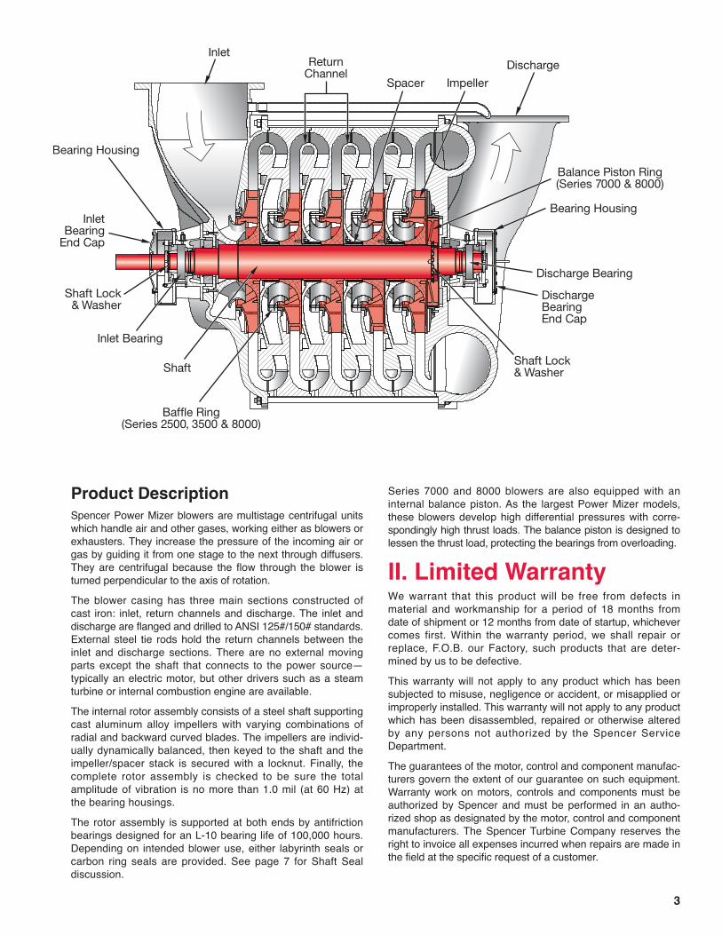
Product DescriptionSpencer Power Mizer blowers are multistage centrifugal unitswhich handle air and other gases, working either as blowers orexhausters. They increase the pressure of the incoming air orgas by guiding it from one stage to the next through diffusers.They are centrifugal because the flow through the blower isturned perpendicular to the axis of rotation.The blower casing has three main sections constructed ofcast iron: inlet, return channels and discharge. The inlet anddischarge are flanged and drilled to ANSI 125#/150# standards.External steel tie rods hold the return channels between theinlet and discharge sections. There are no external movingparts except the shaft that connects to the power source—typically an electric motor, but other drivers such as a steamturbine or internal combustion engine are available.The internal rotor assembly consists of a steel shaft supportingcast aluminum alloy impellers with varying combinations ofradial and backward curved blades. The impellers are individ-ually dynamically balanced, then keyed to the shaft and theimpeller/spacer stack is secured with a locknut. Finally, thecomplete rotor assembly is checked to be sure the totalamplitude of vibration is no more than 1.0 mil (at 60 Hz) atthe bearing housings.The rotor assembly is supported at both ends by antifrictionbearings designed for an L-10 bearing life of 100,000 hours.Depending on intended blower use, either labyrinth seals orcarbon ring seals are provided. See page 7 for Shaft Sealdiscussion.
Series 7000 and 8000 blowers are also equipped with aninternal balance piston. As the largest Power Mizer models,these blowers develop high differential pressures with corre-spondingly high thrust loads. The balance piston is designed tolessen the thrust load, protecting the bearings from overloading.
II. Limited WarrantyWe warrant that this product will be free from defects inmaterial and workmanship for a period of 18 months fromdate of shipment or 12 months from date of startup, whichevercomes first. Within the warranty period, we shall repair orreplace, F.O.B. our Factory, such products that are deter-mined by us to be defective.This warranty will not apply to any product which has beensubjected to misuse, negligence or accident, or misapplied orimproperly installed. This warranty will not apply to any productwhich has been disassembled, repaired or otherwise alteredby any persons not authorized by the Spencer ServiceDepartment.The guarantees of the motor, control and component manufac-turers govern the extent of our guarantee on such equipment.Warranty work on motors, controls and components must beauthorized by Spencer and must be performed in an autho-rized shop as designated by the motor, control and componentmanufacturers. The Spencer Turbine Company reserves theright to invoice all expenses incurred when repairs are made inthe field at the specific request of a customer.
3

III. Safety Precautionsand OperatingGuidelines
• Read and follow all instructions in this manual. If you haveany questions, consult your Spencer Representative.
• Use appropriately rated lifting equipment for installation,removal, or disassembly of heavy components.
• Remove inlet and discharge covers, silica gel bags andcrating materials prior to blower installation.
• Inspect all openings for tools and foreign matter beforeconnecting accessories or piping.
• Perform all installing and operating procedures with care,following sound practices to avoid accidents and damage.
• Avoid climbing on or over the blower; use proper stagingand ladders for exterior machine access.
• Be sure isolation pads are correctly located beneath theblower base. See page 5.
• Confirm that the blower is level so that oil level readings willbe accurate.
• Install flexible connectors on inlet and discharge flanges toisolate piping loads from the blower.
• Ensure that piping, machine guards and accessories suchas filters or valves are properly installed and fastened.
• Fill oilers of oil-lubricated blower bearings with recommendedtype of fresh oil as instructed on page 7.
• Install a filter on the inlet when the blower is used in pressureservice and keep it clean.
• Allow only qualified electricians to work on electrical equip-ment.
• Lock electrical circuits open and tag them during servicingof equipment.
• Align the coupling as instructed on page 6.• Remove alignment tools and replace coupling guard before
restarting blower.• Turn the blower shaft by hand to verify free rotation without
rubbing or noise.• Check motor rotation as instructed on page 7.• Do not operate the blower where there is an ambient tem-
perature above 104°F (40°C), unless it has been designedfor such conditions.
• Operate blower with sufficient restriction at all times (viaconnected piping system or throttled butterfly valve) toavoid motor overloading.
• Do not allow blower operation in surge (unstable low flow)or damage may result.
• Rotate shaft of stored or inactive blowers a few times byhand every week.
• Use only genuine Spencer parts for repairs and service.
IV. Handling and StorageEach Spencer blower is carefully balanced and tested at thefactory. For optimum performance, it must be handled withcare during unloading and installation.Check the shipment for damage upon arrival; file any claimswith the shipper and notify Spencer.
Lifting and MovingMoving of this equipment is the customer's responsibility andshould be performed or directed by experienced riggers usingaccepted rigging practices and safety precautions. The blower/motor assembly can be lifted and relocated with an overheadcrane or hoist. Always use lifting equipment rated for theloads involved—see accompanying table of approximatemachine weights.CAUTION: Use of alternative lifting methods such as aforklift is not recommended, due to risk of equipmentdamage or misalignment.Approximate Machine Weights(blower and base without motor)
4
C43 3065 1390C45 4050 1837C46 4517 2049C47 4976 2257C48 5446 2470C52 3543 1607C53 4294 1948C54 5001 2268C55 5708 2589C56 6428 2916C57 7135 3236C58 7810 3574C62 4577 2076C63 5559 2521C64 6515 2955C65 7473 3389C66 8431 3823C72 10150 4604C73 12100 5489C74 14600 6623C75 17200 7804C76 20300 9207C81 14500 6577C82 18000 8165C83 21500 9752C84 25000 11340C85 28500 12927C86 32000 14515
Weight WeightModel No. lb kg Model No. lb kgC13 177 80C14 188 85C15 200 91CS22 913 414CS23 1101 499CS24 1290 585CS25 1478 670CS26 1667 756CS27 1855 841CS28 2044 927CS29 2232 1012CS210 2421 1098C32 1917 870C33 2225 1009C34 2596 1178C35 2928 1328C36 3285 1490C37 3688 1673C38 4004 1816CS32 2130 966CS33 2673 1212CS34 3196 1450CS35 3730 1692CS36 4263 1934CS37 4795 2175CS38 5328 2417CS39 5861 2659C42 2576 1169

Use lifting eyes supplied on the blower base, along with asuitable quad leg chain sling or spreader bars with the smallestpractical angle between the sling legs to minimize stress.CAUTION: Do not use slings around the blower; they willbend or stress the tie rods. Never lift the blower by itsshaft. Do not disturb the oilers or any electrical devices.
StorageIf a blower is stored for an extended period before use orbetween uses, protect it from dampness, dirt and vibration.Suspend bags of silica gel desiccant in the inlet and dis-charge. Cover the entire blower if possible or at least coverthe inlet and discharge openings to keep out foreign matter.Rotate the blower shaft a few times by hand every week,keeping a log.CAUTION: Failure to comply with the required storageprovisions, including weekly shaft rotations, will voidthe warranty.
Unpacking1. Uncrate the blower, saving all literature, boxes and parts.2. Remove inlet and discharge protective caps and all packing
materials.3. Use the packing slip to check off and confirm the presence
of all ordered components.4. Read any instructional and warning labels on the machine
before installation and operation.
V. InstallationNOTE: If any problems are encountered during installation orstartup, consult your local Spencer Representative.
LocationCAUTION: Do not locate blower or controls where theywill be subject to ambient temperatures above 104°F(40°C) during operation, unless specially equipped forhigher temperatures.Power Mizer blowers may be installed outdoors, preferablyunder cover, or indoors. When choosing an indoor location,be sure there is sufficient ventilation to allow unrestricted air-flow to the blower. In addition, it is advisable to leave severalfeet of space around the blower and motor for ease of servicing.Inaccessibility can prove costly.Consideration should be given to the noise generated by thisequipment and its contribution to the ambient noise level.Optional noise reduction accessories include blower casingsound attenuation jackets, filter silencers or silencers for theblower inlet and/or discharge, and silencers for the motor.NOTE: Duct noise attenuation is a customer responsibility.
FoundationCAUTION: Oil-lubricated machines must be level or oillevel readings will be inaccurate.
A level concrete pad is recommended, although any flat levelsurface that can support the machine weight is satisfactory.The blower base should be placed level on the furnishedisolation pads or equivalent. The number and location of padsare important. Pads must be located directly under a supportfor maximum performance. Locate one pad under eachsupporting member of the blower.Locate the motor pads under the vertical motor base sup-ports, not necessarily directly under the motor feet. Four padsper side will avoid any springboard effect. Each pad must beshimmed, if necessary, to ensure that it is carrying its share ofthe load. If lag bolts and nuts are used to restrain the blower,hand-tighten only.NOTE: Spencer does not favor grouting; however groutingmay be used consistent with established practice. Do not useisolation pads when grouting.
Blower SetupCAUTION: Make sure blower inlet and discharge ports areunobstructed before connecting piping to blower.
1. PipingAll piping connected to the blower should be of ample size tominimize frictional loss. All system joints must be airtight;leaky pipes waste air and power.All piping must be properly aligned and supported to avoidstress on the blower and restrained to prevent movementaway from the blower caused by air pressure. Flexible connec-tors must be used to connect piping to the blower.NOTE: The diagram above shows the proper orientation of apiping elbow in-line with the blower shaft. The butterfly valveshould have its shaft at right angles to the blower shaft andthe valve should open as indicated (counterclockwise in thisexample). These steps will assure uniform loading of theblowerʼs first stage.
2. Flexible ConnectorsCAUTION: Connected piping must not touch the blower.Use flexible connectors (expansion joints or rubbersleeves) on both the inlet and discharge to create anisolating gap between blower and piping.
5
InletDischarge
CheckValveFlexible
Connectors
ButterflyValve
(Shim if necessary.)Recommended Pad Locations

3. Butterfly ValveTo regulate (throttle) blower volume and/or pressure, a butterflyvalve may be installed—preferably on the inlet. A valve mayalso be installed on the discharge as an isolation valve.
4. Filters, Silencers and Filter SilencersSpencer blowers will accept a filter or filter silencer, typicallyon the inlet, and a silencer, typically on the discharge. Inletfiltration is recommended for pressure applications.
5. Check ValveCAUTION: A check valve must be installed in the dis-charge line (downstream of any blow-off line) of eachblower operating in parallel, or in the inlet line (upstreamof any bleed line) of each vacuum producer operating inparallel to prevent reverse flow through idle units.Orient the check valve during installation to equalize loadingon the valve shutters. Usually, the hinge post of the checkvalve should be installed perpendicular to the blower shaft. Ifthe check valve is installed in a horizontal piping line, positionthe valve shaft vertically. Make sure the internal moving partscan move freely.
6. ElectricalNOTE: All wiring and electrical adjustments or installationsmust be done by a qualified electrician in accordance with theNational Electrical Code and local codes.CAUTION: The electrical service at the installation sitemust supply the voltage stamped on the motor name-plate. Operation at an incorrect voltage may damage themotor and void its warranty.Electrical Accessories. The following optional safety acces-sories are available from Spencer. For copies of the productbulletins listed, contact your Spencer representative orwww.spencerturbine.com.• Load Control Safety Switch (LCSS) – Bult. No. TDS-223• Electronic Modulating Bleed Control (EMBC) –
Bult. No. TDS-224• Bearing Temperature Monitor Control (BTMC) –
Bult. No. TDS-222• Standard Blower Safety Control Panels (LCSS, BTMC and
VM, Vibration Monitor) – Bulletin No. TDS-237 and TDS-236NOTE: Use of a BTMC, vibration monitor and an LCSS orEMBC may be advisable in crucial or unattended applications,anywhere there are wide load fluctuations, or where machinesare operating at high pressure or vacuum.Both the LCSS and EMBC are designed to prevent a blower orvacuum producer from operating in a low load (surge) condition.
7. Coupling AlignmentGood coupling alignment is critical for smooth machine opera-tion. Pre-startup alignment is necessary and is a customerresponsibility. Spencer recommends that each blower befield aligned using a laser alignment system. Only qualified per-sonnel, following the laser equipment manufacturer's instruc-tions, should attempt coupling alignment.WARNING: DISCONNECT AND LOCK OUT ELECTRICALPOWER BEFORE PERFORMING ALIGNMENT.
Machinery Soft FootImperfections or unevenness between the machine base andany foot of the motor or blower creates a condition known as softfoot, which may be parallel or angular. If uncorrected, soft footleads to increased stress and high vibration. Although both themotor and blower feet were preset at the factory, each foot mustbe checked for soft foot prior to alignment. Any vertical or angularsoft foot that exceeds .003" is excessive and must be corrected.Laser Alignment TechniqueLaser alignment is the only method Spencer uses and the onlyone it recommends. Laser aligned systems have significantadvantages such as reduced maintenance costs and energyconsumption; prolonged life for bearings, seals and couplings;decreased bearing temperatures and lower vibration levels.Many laser systems also identify and measure soft foot conditions.NOTE: Consult an alignment specialist if laser equipment isnot available.Coupling Gap AdjustmentUse of a laser system eliminates the need to “break” thecoupling halves. The coupling gap may be left at the factorysetting. (Kop-Flex model “B” coupling gaps are 1/8" up to size2-1/2" and 3/16" for sizes over 2-1/2".)Alignment should be performed at normal operating tempera-tures. Recommended factory tolerance is ±.004" parallel and1/4° angular at operating conditions.Alignment Tips• Make sure the blower is level before alignment.• Mark the axial location of the motor before alignment as a
reference point to be sure it does not move.• Avoid disturbing any factory-installed shims unless they are
to be replaced.• Do soft foot corrections first; loosen all mounting bolts
before correcting any foot.• During the final vertical adjustment of the motor, work on
one side at a time, loosening the jack bolts first so the motordoes not move laterally as mounting bolts are loosened.
• Use the smallest shim that will slide over the mounting bolts.• Minimize the number of shims. One thick shim and 2–3 thin
shims are usually satisfactory. Never exceed 5 shims.• Remove all traces of dirt or contaminants from shims and
machine parts.• Use stainless steel shims only.• Never reuse shims.CAUTION: After each alignment check, add couplinglubricant if required.Coupling Lubrication (grease lubricated)Two coupling lubrication ports are located 180° apart.Remove the setscrew lube plugs from both ports. Installgrease fitting in one port and rotate the coupling until thegrease fitting is angled down at 45°. Pump lubricant in until itappears at the upper port. Remove the grease fitting; replaceand tighten the lube plugs.WARNING: REPLACE THE COUPLING GUARD BEFORERESTARTING THE BLOWER.
6
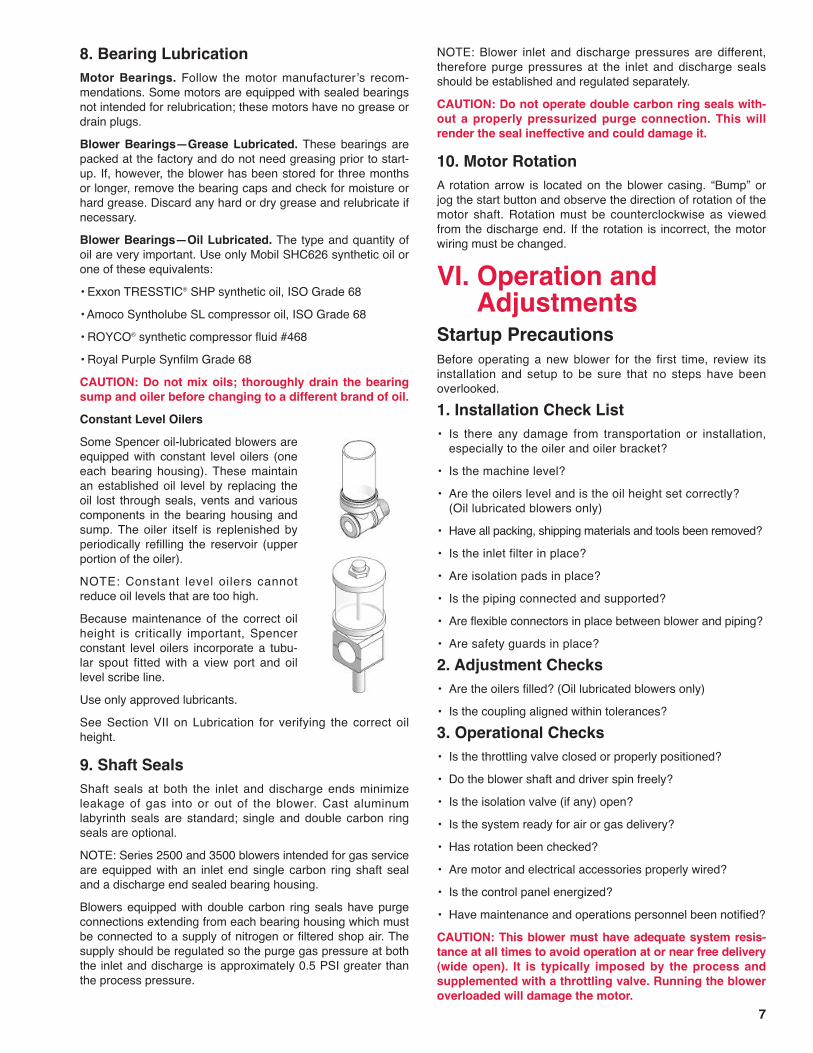
8. Bearing LubricationMotor Bearings. Follow the motor manufacturerʼs recom-mendations. Some motors are equipped with sealed bearingsnot intended for relubrication; these motors have no grease ordrain plugs.Blower Bearings—Grease Lubricated. These bearings arepacked at the factory and do not need greasing prior to start-up. If, however, the blower has been stored for three monthsor longer, remove the bearing caps and check for moisture orhard grease. Discard any hard or dry grease and relubricate ifnecessary.Blower Bearings—Oil Lubricated. The type and quantity ofoil are very important. Use only Mobil SHC626 synthetic oil orone of these equivalents:• Exxon TRESSTIC® SHP synthetic oil, ISO Grade 68• Amoco Syntholube SL compressor oil, ISO Grade 68• ROYCO® synthetic compressor fluid #468• Royal Purple Synfilm Grade 68CAUTION: Do not mix oils; thoroughly drain the bearingsump and oiler before changing to a different brand of oil.Constant Level OilersSome Spencer oil-lubricated blowers areequipped with constant level oilers (oneeach bearing housing). These maintainan established oil level by replacing theoil lost through seals, vents and variouscomponents in the bearing housing andsump. The oiler itself is replenished byperiodically refilling the reservoir (upperportion of the oiler).NOTE: Constant level oilers cannotreduce oil levels that are too high.Because maintenance of the correct oilheight is critically important, Spencerconstant level oilers incorporate a tubu-lar spout fitted with a view port and oillevel scribe line.Use only approved lubricants.See Section VII on Lubrication for verifying the correct oilheight.
9. Shaft SealsShaft seals at both the inlet and discharge ends minimizeleakage of gas into or out of the blower. Cast aluminumlabyrinth seals are standard; single and double carbon ringseals are optional.NOTE: Series 2500 and 3500 blowers intended for gas serviceare equipped with an inlet end single carbon ring shaft sealand a discharge end sealed bearing housing.Blowers equipped with double carbon ring seals have purgeconnections extending from each bearing housing which mustbe connected to a supply of nitrogen or filtered shop air. Thesupply should be regulated so the purge gas pressure at boththe inlet and discharge is approximately 0.5 PSI greater thanthe process pressure.
NOTE: Blower inlet and discharge pressures are different,therefore purge pressures at the inlet and discharge sealsshould be established and regulated separately.CAUTION: Do not operate double carbon ring seals with-out a properly pressurized purge connection. This willrender the seal ineffective and could damage it.
10. Motor RotationA rotation arrow is located on the blower casing. “Bump” orjog the start button and observe the direction of rotation of themotor shaft. Rotation must be counterclockwise as viewedfrom the discharge end. If the rotation is incorrect, the motorwiring must be changed.
VI. Operation andAdjustments
Startup PrecautionsBefore operating a new blower for the first time, review itsinstallation and setup to be sure that no steps have beenoverlooked.1. Installation Check List• Is there any damage from transportation or installation,
especially to the oiler and oiler bracket?• Is the machine level?• Are the oilers level and is the oil height set correctly?
(Oil lubricated blowers only)• Have all packing, shipping materials and tools been removed?• Is the inlet filter in place?• Are isolation pads in place?• Is the piping connected and supported?• Are flexible connectors in place between blower and piping?• Are safety guards in place?2. Adjustment Checks• Are the oilers filled? (Oil lubricated blowers only)• Is the coupling aligned within tolerances?3. Operational Checks• Is the throttling valve closed or properly positioned?• Do the blower shaft and driver spin freely?• Is the isolation valve (if any) open?• Is the system ready for air or gas delivery?• Has rotation been checked?• Are motor and electrical accessories properly wired?• Is the control panel energized?• Have maintenance and operations personnel been notified?CAUTION: This blower must have adequate system resis-tance at all times to avoid operation at or near free delivery(wide open). It is typically imposed by the process andsupplemented with a throttling valve. Running the bloweroverloaded will damage the motor.
7
Blower StartupWith the system connected and the throttling valve closed,turn the blower on. Quickly assess the current draw of themotor. Adjust the system load or throttling valve until thedesired flow is reached, being careful not to exceed the full-rated motor capacity. Initially, blowers will temporarily developmore differential pressure and take more power. Check finalsettings after operating temperature is achieved, typicallyafter one-half hour. If the throttling valve is not fully openwhen the motor capacity has been reached, it should be fixedat this point to prevent further opening and possible overload-ing of the motor.
1. SurgeCAUTION: Do not operate blower in surge (unstable lowflow range). Damage to blower caused by operating insurge is not covered by Spencer warranty.A blower in surge produces a rush or pulsating rhythmic airsound caused when airflow into or out of the blower is restricted.In addition to its characteristic noise, surge may be detected bypower or pressure fluctuations. Surge is potentially destructivebecause it is accompanied by excessive temperatures andaerodynamic forces that will ultimately cause mechanical failure.A surge condition is simply eliminated by increasing the airfloweither into the system or to a bypass or vent. Various surgecontrol devices are also available from Spencer—see page 6.NOTE: If a blower surges violently at startup, avoid recurrencesby leaving the throttling valve open at or near its normaloperating position.
2. Normal Operating LimitsNOTE: Use of a Spencer bearing temperature monitor andvibration monitor is recommended to alert personnel to bloweroperation outside the following limits.• Vibration should not exceed 1.0 mil at each bearing housing
at 60 Hz, or 1.25 mils at 50 Hz.• Bearing temperatures should not exceed 220°F (104°C) at
the bearing housing surface.If abnormal operation is detected, shut the blower down andrefer to the Troubleshooting Guide on page 14 or contactSpencer.
3. Periodic OperationCAUTION: All blowers should be operated periodically.In multiple blower installations, periodically rotate each blowerfrom standby to operating status.
4. Parallel InstallationCAUTION: A check valve must be installed in the dischargeline of each blower or inlet of each vacuum producer oper-ating in parallel to prevent reverse flow through idle units.CAUTION: Do not operate centrifugal blowers in parallelwith positive displacement blowers. Such operation maydamage the centrifugal blowers and will void the warranty.
When operating two or more blowers in parallel (typically iden-tical blowers), each must carry its share of the load. Thecurrent readings of all motors should be approximately thesame. It may be necessary to readjust the individual throttlingvalve stops to attain similar readings.
VII. LubricationWARNING: DISCONNECT AND LOCK OUT ELECTRICALPOWER BEFORE PERFORMING LUBRICATION.CAUTION: Maintain extreme cleanliness to avoid bearingcontamination and damage.
Motor BearingsFollow the motor manufacturerʼs recommendations. Somemotors are equipped with sealed bearings not intended forrelubrication; these motors have no grease or drain plugs.
Blower Bearings—Grease LubricatedUse Chevron SRI #2 grease. Intermixing incompatible greasesor using any other type may result in bearing failure which isnot covered under the Spencer warranty.
Chevron SRI #2 Grease SpecificationsGrade or consistency ...........................................................#2Thickener ...................................................................polyureaASTM Dropping Point ....................................................480°FWork Penetration ...............................................................270Base Oil Viscosity.......................................600 SUS @ 100°FColor ......................................................................Blue-GreenRelubricate approximately every six months, according to thefollowing table.
Recommended Lubrication IntervalsNormal Conditions Extreme Conditions*4000–5000 hours 2000–3000 hours
*Excessive heat, moisture, dust or corrosive conditions.NOTE: More bearing failures are caused by overgreasingthan lack of lubricant. Add grease sparingly and only when thebottom drain plug is open.CAUTION: Keep the grease clean; any dirt or contami-nants will damage the bearings.1. Remove the bottom drain plug.2. Probe the drain with a clean rod to free hardened grease.3. Inject new grease only until old grease appears at the
drain. NOTE: Some housings have two grease fittings.4. Restart the blower with the drain plug still removed to allow
excess grease to escape.5. After normal operating temperature is reached, replace the
drain plug.Lubrication of replacement bearings. Before installing,“butter” both sides of replacement bearings by forcing greaseinto each side until the grease is flush with the race.
8

Blower Bearings—Oil LubricatedGeneral Oil Lubrication InformationCAUTION: If equipped with oiler, keep the oiler at least 1/3full at all times.Use Mobil SHC626 synthetic oil or equivalent (see list, page 7).Each blower is shipped with an adequate amount of MobilSHC626 oil for one oil change. The oil should be changed atleast once a year.1. Drain oil (preferably when hot) by removing the drain plug
in the bearing sump.2. Replace drain plug, fill the oiler and tighten the oiler screw
cap finger tight. See Oil Filling section on page 7.CAUTION: A loose or overtight screw cap will cause oilermalfunction. Do not distort the cap O-ring by overtight-ening.
Oiler TipsThere are several O-rings and gaskets in the oiler; leaks atany point can cause trouble. For example, if there is a leak inthe oiler reservoir, the oiler will overfill the bearing sump.Keep the oiler parts clean—dirt or contamination can initiate aleak.Air leaks above the oil level do not produce bubbles, even asthe oil feeds.Pressures in the oiler and oil sump must be equal. Do notremove the vent line while the blower is operating.Bench Testing OilersUse the following procedure to trouble-shoot malfunctioningoilers that exhibit oil leaks or overfilling.1. Secure oiler so it is level in all directions.2. Plug outlets with pipe plugs.3. Remove fill cap and fill reservoir completely.4. Quickly screw fill cap back on reservoir.NOTE: When you close the fill cap, the check valve opens,allowing oil to fill the view port.5. When the fill cap is tightened securely, the oil in the viewport should seek a level at or near the level mark scribed inthe casting.Let the oiler sit for several hours. If oil fills the view portcompletely and is seeping out the vent hole, the seals arebad. The oiler needs to be repaired or replaced.
Series 2500, 3500Oil Height SettingsPower Mizer Series 2500 and 3500 blowers have nonad-justable oilers hard-piped directly into the sump. There is noneed to check oil height settings but make sure the sump andoiler are level.Filling OilersReplenish oil in the reservoir only after it drops below half full,which will reduce the number of refills. If the oiler needsfrequent filling, this is not normal—look for an oil leak.
Note: Oilers ʻnuisance feedʼ as the reservoir is screwed offand on, which can lead to an overfilled sump. Screw on theoiler reservoir quickly to minimize overfilling. Tighten thereservoir only hand-tight.Allow the oil to stabilize for one hour. Fill the oiler with MobilSHC626 or equivalent, replace the oiler reservoir, and tightenit to allow the oiler to feed. Repeat as necessary until the oilerstops feeding (bubbles stop appearing). The oil level shouldbe at or slightly above the center of the oiler sight glass (lowerportion of oiler).
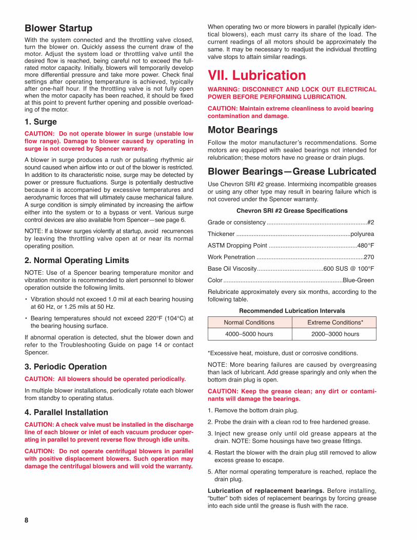
Series 3000, 4000, 5000, 6000Oil Height SettingsThe following instructions apply only to Power Mizer Series3000, 4000, 5000 and 6000 blowers, which have adjustableoilers. Both bearings on these blowers must be checked forproper oil height settings before starting. Oiler level settingsare preset at the factory, but an uneven foundation or shippingdamage can disturb them.CAUTION: Oil height settings are critical. The oil height ina bearing sump must be maintained within a narrowrange to lubricate the bearing correctly. Too much or toolittle oil will lead to excessive heat generation, degradingthe oil and shortening the bearing life.First, be sure the sump and oiler are level. The oiler may beleveled or the oiler height adjusted by loosening the 8mm oilerbracket bolt. Leave some tension on the bolt to keep the oilerfrom moving too freely. With a small carpenterʼs level, line upthe oiler scribe lines with the sump sight glass and set the oilheight as follows.The inlet end bearing oil level scribe line should be set 1/16”below the bearing sump sight glass center. On the dischargeend, however, the oil level scribe line should be even with thesight glass center.Once stabilized, the oil level observed in the view port is theoil height in the oil sump. After initial operation, a ʻrun levelʼ ofapproximately 1/8"-1/4" above the initial setting is normalwhen the blower is idle.
Filling OilersReplenish oil in the reservoir only after it drops below half full,which will reduce the number of refills. If the oiler needsfrequent filling, this is not normal—look for an oil leak.NOTE: Oilers ʻnuisance feedʼ as the cap is screwed off andon, which can lead to an overfilled sump. Screw the oiler capquickly to minimize overfilling. Tighten the cap only hand-tight.
9
Oil Level
Bearing Oiler
10
The fill rate is slow on Series 3000, 4000, 5000, and 6000machines. Let these machines sit, preferably overnight, untilthe oil is stabilized. If waiting is not possible, fill the sumpsfrom the top vent—recognizing that this procedure can resultin high oil levels as oil drains off internal components.
Series 7000, 8000Oil Height SettingsPower Mizer Series 7000 and 8000 blowers have nonad-justable oilers hard-piped directly into the sump. There is noneed to check oil height settings but make sure the sump andoiler are level.Filling OilersReplenish oil in the reservoir only after it drops below half full,which will reduce the number of refills. If the oiler needs fre-quent filling, this is not normal—look for an oil leak.Note: Oilers ʻnuisance feedʼ as the reservoir is screwed offand on, which can lead to an overfilled sump. Screw the oilerreservoir quickly to minimize overfilling. Tighten the reservoironly hand-tight.Allow the oil to stabilize for one hour. Fill the oiler with MobilSHC626 or equivalent, replace the oiler screw reservoir, andtighten it to allow the oiler to feed. Repeat as necessary untilthe oiler stops feeding (bubbles stop appearing). The oil levelshould be at or slightly above the center of the oiler sightglass (lower portion of oiler).Use only approved lubricants (see page 7).CAUTION: Oilers must be filled and checked for properoil level after each oil change.CAUTION: Do not mix oils. Thoroughly drain the bearingsump and oiler before changing to a different oil.
Flexible CouplingsCouplings are lubricated at the factory with Texaco Code 1912coupling grease and should be relubricated with identical orcompatible grease every six months.Two coupling lubrication ports are located 180° apart.Remove the setscrew lube plugs from both ports. Install agrease fitting in one port and rotate the coupling until thegrease fitting is angled down at 45°. Pump lubricant in until itappears at the upper port. Remove the grease fitting andreplace and tighten the lube plugs.
VIII. MaintenanceWARNING: DISCONNECT AND LOCK OUT ELECTRICALPOWER BEFORE PERFORMING MAINTENANCE.
Blower Bearing Removaland ReplacementNOTE: Refer to the appropriate view for the blower seriesinvolved. Some bearing system details may vary from thoseillustrated.CAUTION: Note and record the orientation of the bearinghousing and components, taking care to retain theirposition. Positioning may vary between grease and oillubricated machines.
These illustrations (page 11) and instructions apply to thedrive side of the blower. Bearings on the non-driven side areserviced the same, except the coupling guard, coupling, andmotor need not be removed. Bearing housings are similar onboth the inlet and discharge ends and serviced in a similarmanner.
Series 1500Bearing Removal Procedure1. Remove the belt guard.2. Release the tension in the belt drive and remove the belt.3. Remove the belt pulley from the blower shaft.4. Remove the bearing cap, locknut and lockwasher from the
bearing housing.5. After removal of the bearing housing screws, attach a
flange type puller using the threaded holes for thebearing cap. Carefully remove the bearing housing andthe bearing using the attached puller.
6. Remove the bearing from the bearing housing.Bearing Replacement Procedure1. Install components in reverse order of disassembly, starting
with the installation of the bearing housing onto the blower.2. Ensure that the bearing is completely seated on the shaft.3. Lubricate according to the instructions on pages 8 and 9.Checking and Adjusting Belt Tension1. Remove the belt guard.2. Use a tension checker to measure the belt deflection force
in lbs. Refer to belt catalog tables for the correct deflectionand tension values for your specific combination of belts andpulleys. Correct belt tension has been achieved when themeasured deflection falls within the recommended range.
3. Use the adjustment screws on the motor slide base tomove the motor closer to the blower if belt tension is toohigh, or further from the blower if tension is too low.
4. Replace the belt guard.
Series 2500, 3500Bearing Removal Procedure1. Remove coupling guard.2. Split the coupling halves, recording the relative position of
the motor and blower shafts (not the coupling shells).3. Unbolt and move motor (if required).4. Use puller to remove blower coupling half. Apply heat if
necessary.5. For oil-lubricated bearing, drain all oil by removing drain
plug from the bottom of the bearing sump.6. Remove bearing cap.7. Remove shaft locknut, lockwasher, spacer, oil slinger,
bearing retainer and sump if present.8. Remove bearing housing bolts.9. Using a two-arm puller and the two tapped puller holes
(5/8" or 1/2") in the bearing housing, remove housing, bear-ing, bronze seal and grease slinger, if present, as a unit.
10. ʻDriftʼ the bearing out of the housing. Note: Watch for athrust washer that some bearings have behind the bearing.

11
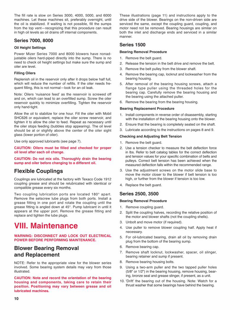
Series 2500, 3500(Oil)
Series 3000, 4000, 5000, 6000(Oil)
Series 7000, 8000(Oil)
Lockwasher
BearingHousing
Bearing
Sump
Gasket
Locknut Spacer
Grease Slinger
Oil SlingerGasket
Bearing CapBearingHousing
Oiler Bracket
Bearing Cap
Vent Hose
Oiler
Feed Hose
LocknutLockwasherBearings, Back to Back
Gasket
BronzeSeal
Oiler (Also availableon Series 2500, 3500)
Bearing CapSlinger Cover
LockwasherOil Slinger
Slinger SpacerBearing Retainer
BearingOrifice
Gasket
Locknut
NOTE: Refer to the appropriateview for the blower series involved.Some bearing system details mayvary from those illustrated.
BearingHousing
Locknut
BearingHousing
Grease Slinger
LockwasherBearing
Bearing CapGasket
BearingHousingSeries 1500
(Grease)
Bearing Cap
LockwasherBearing
Series 2500, 3500(Grease)
Locknut

7. Remove slinger cover, shaft locknut,lockwasher, spacer, oil slinger, andbearing retainer.
8. Open a section of the ball cage on thebearing and cut the swarf out.
9. Using a blind housing puller kit (avail-able from Spencer), insert the appro-priate bearing adapter and rotate it90 degrees to achieve a positive gripwithin the bearing race.
10. Prepare the opposite cage area in thesame manner and insert the secondadapter.
11. Connect both adapters to the main rod.Assemble beam and spindle.
12. Pull out bearing.NOTE: No shaft support is needed; the shaft will be supportedby the labyrinth seals.
Bearing Replacement ProcedureCAUTION: Maintain extreme cleanliness to avoid bearingcontamination and damage. Use new gaskets.1. Install components in the reverse order of disassembly.2. Heat the bearing. Normally a bearing temperature of 80 to
90°C (144 to 162°F) above that of the shaft is sufficient formounting.CAUTION: Never heat a bearing to a temperaturegreater than 125°C (257°F), never heat a bearing usingan open flame.
3. Press the bearing onto the shaft until seated against theshoulder. Pusher kits are available from Spencer.
NOTE: No shaft support is needed; the shaft will be supportedby the labyrinth seals.Bearing Replacement ProcedureCAUTION: Maintain extreme cleanliness to avoid bearingcontamination and damage. Use new gaskets.1. Install components in the reverse order of disassembly.2. Press the bearing onto the shaft until seated against the
shoulder. Pusher kits are available from Spencer.NOTE: If present, oil slinger ʻdimplesʼ should face the bearing.
3. Lubricate according to instructions on pages 8 and 9.
Series 3000, 4000, 5000, 6000Bearing Removal Procedure1. Remove coupling guard.2. Split the coupling halves, recording the relative position of
the motor and blower shafts (not the coupling shells).3. Unbolt and move motor.4. Use puller to remove blower coupling half. Apply heat if
necessary.5. For oil-lubricated bearing, drain all oil by removing drain
plug from the bottom of the bearing sump.6. For oil-lubricated bearing, disconnect oiler tubing and oiler
if necessary.7. Remove bearing cap.8. Remove shaft locknut and lockwasher.9. Remove bearing housing bolts.10. Using a two-arm puller and the two tapped puller holes
(5/8") in the bearing housing, remove housing, bearing(s)and bronze seal, if present, as a unit.
11. ʻDriftʼ the bearing(s) out of the housing.NOTE: No shaft support is needed; the shaft will be sup-ported by the labyrinth seals.
Bearing Replacement ProcedureCAUTION: Maintain extreme cleanliness to avoid bearingcontamination and damage. Use new gaskets.1. Install components in the reverse order of disassembly.
NOTE: If the assembly is equipped with a bronze rotationshaft seal, start the seal on the shaft, but do not seat.
2. Press the bearing(s) onto the shaft until seated againstthe shoulder. Pusher kits are available from Spencer.NOTE: Double bearings must be installed back-to-back.
3. Lubricate according to instructions on page 9.
Series 7000, 8000Bearing Removal Procedure1. Remove coupling guard.2. Split the coupling halves, recording the relative position of
the motor and blower shafts (not the coupling shells).3. Unbolt and move motor.4. Use puller to remove blower coupling half. Apply heat if
necessary.5. Drain all oil by removing drain plug from the bottom of the
bearing sump.6. Remove bearing cap.
12
Labyrinth Seal Removal andReplacementNOTE: Labyrinth seals are non-contacting and do not wear,but if a seal is damaged during bearing replacement, leakagewill increase and the seal should be replaced.1. Remove the bearing housing,
following the appropriate bear-ing removal instructions in thismanual.
2. Remove the heat fan if pre-sent. Disk-type heat fans aresecured by two setscrews;bladed heat fans are clampedto the shaft.
3. Support the shaft and slide theseal clear. Gently lower theshaft.
4. Slide the new seal onto theshaft, raise and recenter theshaft, then seat the seal andfasten securely.CAUTION: Use care; the seal material is soft andeasily damaged.
5. Disk-type heat fan: Use a feeler gage to position the fan .050"from the seal face and tighten.Bladed heat fan: Center the fan between the seal face andthe bearing journal and tighten.
6. Replace bearing(s) following the appropriate bearingreplacement instructions in this manual.
Labyrinth Seal

13
Field-Replaceable PartsWhen ordering parts provide full information about yourSpencer equipment, including the serial number and modelnumber. Field-replaceable parts are restricted to the following:• Drive end motor bearing• Opposite drive end motor bearing• Inlet bearings• Discharge bearing• Labyrinth seal or carbon ring• Bearing cap gaskets
Equipment ServiceSpencer provides prompt, courteous factory and field servicefor all Power Mizer machines. To determine the nature of thedisorder and the best way to correct it, service personnel willbe dispatched to your location. We typically request a PurchaseOrder prior to sending service personnel; however we willproceed on verbal orders in an emergency.Once a full evaluation of the equipment has been performedby our service personnel, you will be advised if the servicework is covered by the Spencer warranty. For out-of-warrantyservices, please note that we accept Visa and MasterCardcharges as well as other forms of payment.NOTE: Spencer products returned to the factory must be sentfreight prepaid and accompanied by a Return Service Order
PROBLEM Possible Cause Corrective Action
Indication: machine design capacity too small for the system
INSUFFICIENTAIR OR GASTHROUGHSYSTEM
Indication: low pressure/vacuum or volume as determined by gage measurement or process• Incorrect rotation.• Air or gas lines too small, causing
excessive friction loss.• Valves in line not fully open or check
valve improperly installed.• Inlet, discharge or piping system
partially blocked.• High inlet temperature.• Low inlet pressure.
• Machine not running at design speed.
• Low gas density or specific gravity.
• Machine air passages clogged.• Impellers damaged by explosion, abra-
sion or vibration.• Pressure or vacuum gage inaccurate.
Change motor leads to correct rotation.Increase line sizes or install machine with higher outputpressure.Open valves or inspect check valve.
Remove obstructions, clean filter.
Position inlet in a cooler area.Check inlet for obstructions or install machine with higher dis-charge pressure.Refer to motor manufacturerʼs instructions; check motorspeed; check voltage connections.Check gas analysis and increase density or install machinedesigned for prevailing conditions.Consult Spencer Service Department.Consult Spencer Service Department.
Calibrate gage; always use a “U” tube manometer for check-ing pressure and/or vacuum.
• System requirements incorrectlycalculated by customer.
• System leaks or too many openings.
Install larger volume or lower pressure machine to handlesystem requirements.Locate and repair leaks, reduce number of openings.
Indication: measuring gas or air flow incorrectly• Flowmeters calibrated incorrectly.
• No means of measurement available.
Calibrate flowmeters; use proper orifice for meter (check withflowmeter manufacturer).Obtain and install flowmeter.
(RSO) issued by the Spencer Service Department after wereceive your Purchase Order. Service costs will be quoted afterinspection and the work will be performed upon written accep-tance of the quotation.
Material Safety Data SheetsSpencer is committed to ensuring the safety of its employees. IfSpencer equipment has been exposed to potentially hazardouscontaminants or if Spencer service personnel could be exposedto a potentially hazardous field environment, a Material SafetyData Sheet (MSDS) is required (a) prior to dispatching Spencerservice personnel or (b) before receipt of any equipment for fac-tory service. If special precautions are necessary to work on theequipment, contact the Spencer Service Manager.
Emergency ServiceEmergency service calls after normal working hours can berouted through our voice mail system at 1-800-232-4321 and aSpencer service representative will return your call promptly.
Service and Operating AssistanceSpencer Representatives are always available to help customersachieve maximum equipment performance and reliability. Likewise,Spencer service personnel will provide on-site instruction duringfield service calls in the proper procedures to avoid a recurrence ofthe problem encountered.
IX. Troubleshooting Guide

14
Indication: motor malfunction• Abnormal hum or whine.
• Low voltage, motor not up to speed.• High voltage (causes noise and
burnout).• Bearing noise (see previous
instructions for blower bearings).• Loose part in motor.• Low frequency.
Check motor manufacturerʼs instructions; check voltagesupply and connections.Correct improper voltage.Correct improper voltage.
Tighten, repair or replace (check with motor manufacturer).Correct improper frequency.
MOTOR HOT (Check with surface thermometer; consult Spencer Service Department for assistance)• Ambient temperature too high for insu-
lation class.• Incorrect voltage.• Incorrect cycle.• Electrical short-circuit insulation
failure.• Motor overloaded, too much air
passing through blower.
Cool motor or replace with motor having proper insulation.
Change to correct voltage.Change to correct cycle.Repair or replace motor.
Check for system leaks, throttle back butterfly valve, installlarger motor.
MACHINENOISY
Indication: machine malfunction – bearing whining or growling• Bearing hot.
• Bearing failure.• Bearing retainers worn.• Bearing turning on shaft, retaining nut
loose.• Bearing turning in housing, housing worn.• Bearing replaced incorrectly (e.g.,
angled, cramped or reversed).
Check lubricant, add or drain as necessary. Be sure oiler isfunctioning properly and screw cap is tightened properly.Replace bearing(s).Replace bearing(s).Tighten nut, check for damage.
Replace housing and bearing.Follow installation directions carefully, check bearing, shaftand housing dimensions.
Indication: machine malfunction – internal noise• Impellers worn due to age or abrasion
from dirty air or gas.• Machine in surge (see page 8).• Machine running rough, out of balance.• Coupling misaligned and/or out of
grease.• Foreign matter in machine.
• Impellers or shaft sleeve hitting.
Correct abrasive conditions if present; consult SpencerService Department regarding impeller replacement.Increase airflow.Consult Spencer Service Department.Check alignment, realign if necessary; check coupling forwear, replace if worn; relubricate as instructed.Consult Spencer Service Department regarding machinecleaning; install inlet filter to prevent clogging.
Consult Spencer Service Department.
IX. Troubleshooting Guide (cont.)PROBLEM Possible Cause Corrective Action

IX. Troubleshooting Guide (cont.)PROBLEM Possible Cause Corrective Action
Indication: mechanical fault• Material buildup on impellers.
• Shaft bent.• Bearing failure.• Unbalanced replacement motor
installed.• Internal parts hitting.• Impeller failure.• Coupling misaligned.• Inlet and/or discharge piping
connected to machine without flexibleconnector, causing torque or stresson casing.
• Machine bolted down, causingmisalignment.
• Bearing(s) cramped due to improper fit.• Piping not adequately supported.• Incorrect motor voltage, causing
assembly to operate at improperspeed.
• Solids passing through machine.
• Soft foot on motor or blower.• Machine in surge (see page 8).• Harmonic pulsation from gasoline
engine driver.• Machine not mounted on solid
foundation.
Consult Spencer Service Department for cleaninginstructions, install inlet filter to prevent further buildup.Consult Spencer Service Department.Replace bearing(s).Balance motor.
Consult Spencer Service Department.Consult Spencer Service Department.Align coupling.Install flexible connectors at inlet and discharge.
Remove bolts, use dowel pins or set in guide channels.
Check bearings, shaft and housing, correct bearing fit.Anchor piping properly beyond flexible connector.Check voltage and wiring connections, correct voltage.
Consult Spencer Service Department regarding machinecleaning, install inlet filter to prevent further contamination.Follow alignment procedure on page 6.Increase airflow.Change engine speed to remove pulsation.
Reinforce foundation.
VIBRATINGMACHINE
Indication: Oil leaking from bearing housing• System component tilted. Make sure blower, oil sump and oiler are level.• High oil level causing air Decrease oil level in reservoir.
bubbles in oil and high oiltemperatures.
• Adjustable oiler at improper Reset oil height—see page 9.height setting (Series 3000,4000, 5000, 6000 blowers).
• Air leak in oiler reservoir. Check O-rings and gaskets, remove dirt andcontamination. See Bench Testing Oilers, page 9.
• Vent line missing or Install or reconnect vent line.disconnected.
• Oiler cap removed and replaced Screw cap on and off quickly; refill only when oiltoo slowly or too often, level is down to 1/4 full.allowing ʻnuisance feeding.ʼ
• Loose or overtightened Hand-tighten cap, make sure O-ring is clean andoiler cap. in good condition.
• Loose fittings. Tighten fittings.
OIL LEAKS
15

Form WW6.1, Copyright ©2009 The Spencer Turbine Company 012609KBA
Blowers & Vacuum Systems with an Engineering EdgeThe Turbine Company, 600 Day Hill Road Windsor CT 06095-4706
TEL 800-232-4321 • 860-688-8361 • FAX 860-688-0098 • www.spencerturbine.com
Products & Services®
Industrially rated products offeringeffective solutions for air and gasmoving problems:• Multistage centrifugal blowers• Single stage centrifugal blowers• Gas boosters & hermetic gas boosters• Regenerative blowers• Modular central vacuum systems• Mobile or stationary integrated vacuum
systems• Separators and dust collectors• Custom-engineered products with special
materials for extreme temperatures andpressuresComplementary accessories withsingle source convenience andcompatibility:• Standard and custom electrical control
panels – UL, CUL Listed and C.E.Compliant available
• Dissolved oxygen control systems• Comprehensive selection of tubing, fittings,
vacuum hose, valves and tools• Valves, gauges, couplings, shrink
sleeves, vibration isolators and othersystem componentsComprehensive engineering andother customer support services:• The industryʼs largest complement of
technical specialists in air and gasmoving technology
• Worldwide parts and service organization• Application research and testing facilityWorldwide organization of salesrepresentatives and distributorsoffering:• Product selection, installation and operation
assistance• Comprehensive system design services• Follow-up services and troubleshooting
For the name and telephone number of your localSpencer Representative, call 1-800-232-4321
or email [email protected]