serie l9 - euro-cobil.comeuro-cobil.com/wp-content/uploads/pdf/brandoni/serie_l9_2014.pdf · nbr...
TRANSCRIPT

68 www.brandoni.it
Shu
t-of
f val
ves
Serie L9
FIRE FIGHTING
Application fields
LUG butterfly valve
WATER CONDITIONING GAS HEATING DRINKING WATER INDUSTRY
C H I N A
BR
ANDONI
made in

www.brandoni.it 69
Shu
t-of
f val
ves
4
7
5
1
3 2
6
Cat2011_L9_p2.drw1_spaccato_BN
Serie L9
In conformity with directive 97/23/CE PEDIn conformity with D.M. 174 (directive 97/83/CE)
Construction and testing norms (correspondences):
Face-to-face: EN558/1-20 (ISO 5752-20, DIN 3202K1)Flanges: EN1092, ANSI B16.5 #150Design: EN593, EN13445, ISO 5211, EN12570Marking: EN19Testing: 100% testing in accordance with EN 12266 cat. A (ISO 5208 cat. A)
The shut-off LUG butterfly valves in Series L9, with a centred Disc and LUG type body, are made of ductile iron, manufac-
tured in accordance with severe product norms and in conformity to EN ISO 9001.
These valves are suitable for heating and conditioning (HVAC), water treatment and water distribution, industrial applica-
tions, agricultural purposes, for compressed air, gas, oils and hydrocarbon.
(Please ensure the choice of the corresponding item)
YES: for in line and end of line installation with frequent actuation; the integrated support, in accordance with ISO 5211,
allows easy mounting of a wide range of actuators and drives.
They are suitable for choking and regulating the flow.
NO: for steam.
Accessories Actuators
Extension for water main system connection
Position indicator and padlocking for gear box
Micro-switch for gear box
Kit: micro-switches for ON/OFF position
indicator
Double acting and single acting pneumatic actuators
On request: micro-switches, position indicators
Electric actuators
Gear box
Chain driven control
Refer to specifications on page 75
1. Epoxy coating.
2. Lever suitable for intermediate regulation.
3. Lockable operation lever.
4. A notch machined at the top of the stem indicates the position of the disc and allows adjusting the command to the correct position, when the command/lever is removed.
5. Compact design.
6. Integrated ISO 5211 flange.
7. Threaded holes suitable for mounting between PN16 for DN25-300 flanges (on request PN 10) and for mounting between PN 10 for DN 350-600 flanges.

70 www.brandoni.it
Shu
t-of
f val
ves
J
BZ
B
J
R
min
. pip
e
W
Parallel key ISO R773 / DIN6885A
E
S
ISO5211
n° x q
DN350-600
G
L1
D
O
L
F2
L9 D
N30
0-60
0L9
DN
25-2
50
DN25-300
9
F1D
n° x M
ISO5211
n° x q
G
8
6
7
5
3
4
2
5
1
C
E
A
L2
T
E
S
L9 D
N25
-250
L9 D
N30
0-60
0LUG butterfly valve

www.brandoni.it 71
Shu
t-of
f val
ves
Serie L9
123456789
10
Component
BodyDiscStem LinerBushingWasherCirlclip ISO3075O-ringLeverBolts
Material
EN GJS 400 - 15 EN GJS 400 - 15 nickel plated / ASTM A351 gr. CF8-M / CuAl11Fe4 ASTM B148 C94500AISI 420EPDM / NBR / FKM (Viton®) / PTFEPTFEGalvanized carbon steelSpring steel FKM (Viton®)DN25-150 aluminium / DN 200-250 EN GJS 400-15Galvanized carbon steel
Materials
Operating torque (Nm)
DN 25 32 40 50 65 80 100 125 150 200 250 300 350 400 450 500 600A 33 33 33 43 46 46 52 56 56 60 68 78 78 102 114 127 154ØC 65 73 82 89 102 118 150 174 205 260 318 376 438 489 539 594 695D 104 110 116 126 136 150 170 180 200 230 266 292 368 400 422 480 562B 51 56 63 62 69 90 106 119 131 166 202 235 267 297 318 355 444F1 192 192 170 170 170 206 206 285 285 400 530 - - - - - -Z 68 68 50 50 50 69 69 90 90 72 72 - - - - - -F2 130 130 130 130 130 130 130 130 130 235 226 226 216 216 216 256 285L 102,5 102,5 102,5 102,5 102,5 102,5 102,5 102,5 102,5 190 190 190 183 183 183 311 386T 65 65 65 65 65 65 65 65 65 78 80 80 80 80 80 125 136L1 110 110 110 110 110 110 110 110 110 155 170 170 151 151 151 214 262L2 130 130 130 130 130 130 130 130 130 176 200 195 188 188 188 275 324W 45 45 45 45 45 45 45 45 45 63 81 81 80 80 80 168 293O 150 150 150 150 150 150 150 150 150 300 300 300 285 285 285 285 385R - 1 5 5 9 17 26 34 50 71 91 112 128 144 163 182 219D min pipe - 12 27 31 45 65 90 110 146 194 241 291 324 379 428 475 573
n x M 4 x M12 4 x M16 4 x M16 4 x M16 4 x M16 8 x M16 8 x M16 8 x M16 8 x M20 12 x M20 12 x M24 12 x M24 16 x M20 16 x M24 20 x M24 20 x M24 20 x M27
ISO 5211 F05 F05 F05 F05 F05 F05 F05 F07 F07 F10 F12 F12 F12 F14 F14 F14 F16G 65 65 65 65 65 65 65 90 90 1 25 1 50 1 50 1 50 175 175 175 210J 50 50 50 50 50 50 50 70 70 1 02 1 25 1 25 1 25 140 140 140 165n x q 4 x 7 4 x 7 4 x 7 4 x 7 4 x 7 4 x 7 4 x 7 4 x 9 4 x 9 4 x 11 4 x 13 4 x 13 4 x 13 4 x 18 4 x 18 4 x 18 4 x 22S 7 7 9 9 9 11 1 1 1 4 1 4 1 7 27 27 31,6 33,15 38 41,15 50,65E 32 32 21 21 21 21 21 27 27 27 27 27 45 51,2 51,2 64,2 70,2
DP bar3 2,9 4,7 7,8 11,3 17 23 33 48 68 120 189 290 298 481 930 1250 22706 3,1 5,1 8,4 1 2 1 8 25 36 54 78 134 212 316 347 551 980 1350 250010 3,3 5,4 8,8 13 20 26 40 61 88 148 234 342 396 622 1200 1500 270016 3,4 5,7 9,2 13 21 28 44 68 99 162 257 367 - - - - -
L9 with lever 2,6 2,6 2,3 3,2 4,1 5,4 6,7 9,6 10,8 21,1 32,7 41,2 - - - - -L9 with gear box 6,2 6,2 6,1 7,0 7,9 9,2 10,5 12,9 14,1 28,4 42,0 50,5 79,3 122,6 254,8 228,3 308,6
1: please refer to Instruction and Recommendations
Dimensions (mm)
Weight (kg)
Mounting between flanges 1 EN 1092 pN16 EN 1092 pN10
N.B.: In order to choose the right actuator, we recommend multiplying the operating torque figure by a safety coefficient, K=1.5

72 www.brandoni.it
NB: the maximum working pressure decreases while the temperature increases; please refer to “pressure/temperature” chart
Shu
t-of
f val
ves
10
100
125
150
200
250
mc/h400001000100
65
0,6
0,8
0,5
1
8
6
5
3
2
10
10000
8040 50 300
400
350
450
600
500
m H2O
Temperature min ° C Max°C
continuous peak
EPDM -10 120 130
NBR -10 80 90
FKM (Viton®) -10 150 170
PTFE -10 120 120
Head loss Fluid: water (1m H2O = 0,098bar) - Head loss with shutter completely open
Pressure/temperature chart
Maximum pressure Temperature
RANGE NOT SUITABLE FOR STEAM. DO NOT use when temperature and pressure are below the liquid-steam saturation line ( hatched area )
Fluids * Mounting
Hazardous gases
Non-hazardous gases
Hazardous fluids
Non-hazardous fluids
BETWEEN FLANGES16 bar DN25-200
10 bar DN250-350NO DN400-600
16 bar DN25-30010 bar DN350-500
6 bar DN600
16 bar DN25-40010 bar DN450-600
16 bar DN25-40010 bar DN450-600
END OF LINE
10 bar DN25-100NO DN125-600
10 bar DN25-3006 bar DN350-500
4 bar DN600
10 bar DN25-4006 bar DN450-600
10 bar DN25-4006 bar DN450-600
232
bar
°C
10
20 40 60 80 100 160140120
psi
145
68 248 284 320212176140104 °F
1
Liquid - steam saturation line (fluid: water)
18
16
14
8
6
12
4
229
58
87
116
174
261
203
LUG butterfly valve
*: Hazardous gas, liquids (explosive, inflammable, toxic) in accordance with 97/23/CE PED and 67/548/EEC

www.brandoni.it 73
Shu
t-of
f val
ves
0
10
20
30
40
50
60
70
80
90
100
0 10 20 30 40 50 60 70 80 90
%
Opening angle (°)
Low
er
reg
ula
tion
an
gle
Up
pe
r re
gu
latio
n a
ng
le
Kv - DN chart (mc/h per bar )
Flow rate / opening position chart Flow percentage on the flow at full opening under the same loss of head.
Serie L9
mm 40 50 65 80 100 125 150 200 250 300 350 400 450 500 600ins 1" 1/2 2" 2" 1/2 3" 4" 5" 6" 8" 10" 12" 14" 16" 18" 20" 24"10° 0,04 0,05 0,09 0,17 0,26 0,43 0,69 1,73 2,6 3,5 5,2 6,9 9,5 12 1920° 2,1 2,6 5,2 7,8 15 25 39 77 130 202 292 401 531 683 105530° 4,8 6 10 16 31 53 82 162 276 427 617 849 1124 1445 223440° 10 13 22 34 67 115 177 352 599 926 1376 1839 2437 3133 484050° 19 23 39 60 120 205 316 628 1068 1650 2384 3279 4342 5609 862660° 30 38 65 100 199 339 522 1038 1768 2730 3945 5425 7185 9238 1427270° 48 60 103 158 314 535 827 1643 2798 4322 6243 8585 11371 14620 2258780° 73 91 161 237 471 803 1241 2465 4196 6483 9364 12878 17057 21930 3388290° 79 99 169 261 518 883 1364 2708 4611 7124 10291 14152 18743 24099 37232
DN
OP
EN
ING
AN
GLE
74 www.brandoni.it
Shu
t-of
f val
ves
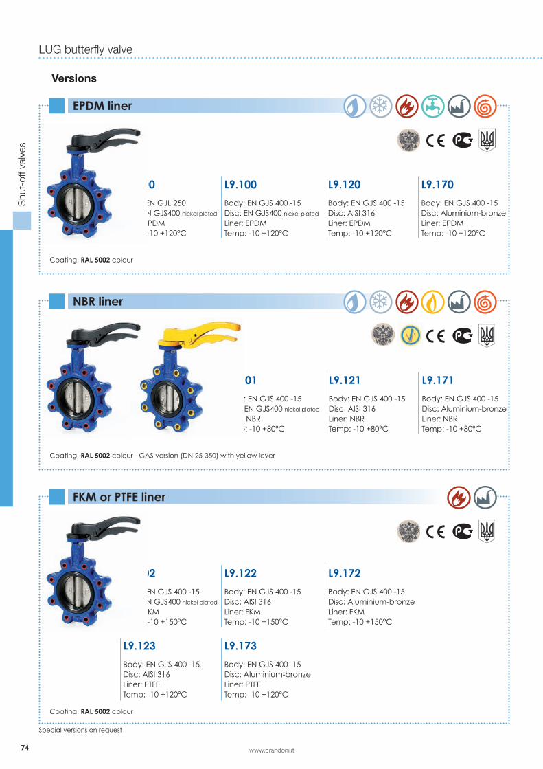
LUG butterfly valve
Versions
EPDM liner
NBR liner
FKM or PTFE liner
Coating: RAL 5002 colour
Coating: RAL 5002 colour - GAS version (DN 25-350) with yellow lever
Coating: RAL 5002 colour
Special versions on request
L9.101
Body: EN GJS 400 -15Disc: EN GJS400 nickel plated
Liner: NBRTemp: -10 +80°C
L9.121
Body: EN GJS 400 -15Disc: AISI 316Liner: NBRTemp: -10 +80°C
L9.171
Body: EN GJS 400 -15Disc: Aluminium-bronzeLiner: NBRTemp: -10 +80°C
L9.000
Body: EN GJL 250Disc: EN GJS400 nickel plated
Liner: EPDMTemp: -10 +120°C
L9.100
Body: EN GJS 400 -15Disc: EN GJS400 nickel plated
Liner: EPDMTemp: -10 +120°C
L9.120
Body: EN GJS 400 -15Disc: AISI 316Liner: EPDMTemp: -10 +120°C
L9.170
Body: EN GJS 400 -15Disc: Aluminium-bronzeLiner: EPDMTemp: -10 +120°C
L9.102
Body: EN GJS 400 -15Disc: EN GJS400 nickel plated
Liner: FKMTemp: -10 +150°C
L9.122
Body: EN GJS 400 -15Disc: AISI 316Liner: FKMTemp: -10 +150°C
L9.172
Body: EN GJS 400 -15Disc: Aluminium-bronzeLiner: FKMTemp: -10 +150°C
L9.123
Body: EN GJS 400 -15Disc: AISI 316Liner: PTFETemp: -10 +120°C
L9.173
Body: EN GJS 400 -15Disc: Aluminium-bronzeLiner: PTFETemp: -10 +120°C

www.brandoni.it
Limit switches kit for ON-OFF indication
Chain driver kit
75
Shu
t-of
f val
ves
1
2
A
B
DN 25 -150 200-400A 100 120B 60 80
1) Position indicator2) Chain for padlocking
Accessories for series J9 - L9
J
ISO5211
n x q
G
EH
S
DN 40-100 125-150 200 250-300H 250-500-800-1000ISO5211 F05 F07 F10 F12G 65 90 125 150J 50 70 102 125n° x Ø q 4 x 7 4 x 9 4 x 11 4 x 13E 20 26 26 26S 11 14 17 27
Stem extension for water main system connection
Position indicator and padlocking for gear box
Limit switches box for gear box
L9.171
Body: EN GJS 400 -15Disc: Aluminium-bronzeLiner: NBRTemp: -10 +80°C
160
114
Box_micro__tab_dim.xls
112 128
M20
x1.5
Mechanical switches per standard. Available on request: proximity switches, ATEX explosion proof proximity switches.
Serie J9 - L9

76 www.brandoni.it
Butterfly valves
Shu
t-of
f val
ves
The information provided here is delivered with each product, and contains “Instructions for use and maintenance”; it is also available on our website: www.brandoni.it (download section)
INSTALLATION AND TRANSPORT- Keep in dry and closed place.- While stored, the disc must be partially open (Fig. 1).- Avoid knocks, take special care to protect lever, hand wheel, gear boxes/actuators.- Do not use lever or hand wheel to lift the valve. MAINTENANCEThe valve does not require maintenance.
RECOMMENDATIONSBefore carrying out maintenance or dismantling the valve, be sure that the pipes, valves and liquids have cooled down, that the pressure has decreased and that the lines and pipes have been drained in case of toxic, corrosive, inflammable or caustic liquids.Temperatures above 50°C and below 0°C might cause damage to people.
INSTALLATION- Handle with care.- Do not weld the flanges to the piping after installing the valve.- Water hammers might cause damage and ruptures. Inclination, twisting and misalignments of the piping may subject the valve to stress, once installed. It is recommended that elastic joints be used in order to reduce these effects as much as possible. The disc must be partially open (Fig. 1).
FIG. 1 FIG. 2 FIG. 3
The stem has a machined notch N (Fig. 2), which indicates the position of the disc; consider this indication, in order to mount the levers and actuators correctly.The mounting can be made with the stem axis in a horizontal or vertical position. In case the fluid contains suspended solid particles (for example, sand, impurities, etc.) o solid particles that may leave deposits, it is recommend that the valve be installed with its axis horizontal, and in such a way that the bottom end of the disc opens in the direction of flow, F. (Fig. 3)The item L9 allows the dismantling of the pipes downstream, for pressures below 6 bar. For end of line installation:- SERIES J9 (all pressures), series L9 (pressure > 6 bar): counter flange MUST be installed- SERIES L9 (pressure< 6 bar): it is recommended that a counter flange be installed.Verify maximum working pressure and limits of use under section “maximum pressure”.Place the valve between two flanges. While placing the valve, ensure there is sufficient space in order in order not to dam-age the rubber. Do not mount seals between valve and flanges (Fig. 1). Carefully clean the contact surface. Do not install the butterfly valve in direct contact with a rubber surface (for example, expansion joints); the best installation is when the rubber is in contact with metal (Fig. 4).In order to achieve correct working, the internal diameter of the pipe must be greater than the value indicated in the chart. Do not weld the flanges to the tube if the valve has already been installed. It is recommended that the flanges listed in the chart be used. As far as possible, avoid flat flanges for welding (EN 1092 01 type); if these flanges are used, ensure perfect centring between the flange and valve, and be sure to weld exactly edgewise to the flange. Do not let protrusions or sharp edges on the piping cause damage to the rubber surface of the valve (Fig. 5).
Instruction and Recommendations for series J9 - L9
N
NO NO
F
FIG. 4
NO
FIG. 5

www.brandoni.it
Shu
t-of
f val
ves
Serie J9 - L9
77
Centre the valve on holes while using wafer type valves.Tighten the bolts crosswise and progressively, in order to distri-bute the pressure equally before the body and flanges come into contact with each other. (Fig. 6)With regard to the Lug version, check that the screws are the correct length, in order to allow complete compression of the lining rubber.Turbulences of the fluid might increase erosion and reduce the life-cycle of the valve. Install the valve at a distance of at least 1 x DN upstream, and at a distance of 2-3 x DN down-stream, away from fittings or bends.In the open position, the valve is larger than the nominal Face to Face value.Check that no other components of the piping interfere or create damage or malfunction (Fig. 7A). If they do, a spacer should be inserted for the valve to operate correctly (Fig. 7B).
FIG. 6
NON OK OK FIG. 7A FIG. 7B
FLANGES CHART
Norms
EN 1092-1PN6/10/16
ANSI B16.1 #150* ANSI B16.5 #150*
Type
Type 11 weld neckType 21 integralType 02 + 35 loose plate with weld ring neckType 02 + 36 loose plate with pressed collarType 04 + 34 loose plate with weld neck collar
flat face
raised face
lap joint
CHART MINIMUM DIAMETER OF PIPES
DN 25 32 40 50 65 80 100 125 150 200 250 300 350 400 450 500 600Ø min. pipe - 12 27 31 45 65 90 110 146 194 241 291 324 379 428 475 573