series 1 rotary cutter - farm king- agricultural … · series 1 rotary cutter ... buhler...
TRANSCRIPT


Series 1 Rotary Cutter
TABLE OF CONTENTS
DESCRIPTION PAGE NUMBER Warranty 1 Safety Message 2 Safety Signs 5 Operating Instructions 6 Service Instructions 7 Assembly Instructions 8 4’ & 5’ Series 1 Rotary Cutter Drawing 9 4’& 5’ Series 1 Rotary Cutter Parts List 10 Chain Kit Drawing & Parts List 12 Chain Kit Assembly Instructions 13 #410 & #510 PTO Shaft Drawing & Parts List 14 #410 Gearbox Drawing 15 #410 Gearbox Parts List 16 #510 Gearbox Drawing 17 #520 Gearbox Parts List 18 Bundles 19

Series 1 Rotary Cutter
1
WARRANTY POLICY Buhler Manufacturing products are warranted for a period of twelve (12) months (90 days for commercial application) from original date of purchase, by original purchaser, to be free from defects in material and workmanship under correct, normal agricultural use and proper applications. Buhler Manufacturing’s obligations under this warranty shall be limited to the repair or exchange, at Buhler Manufacturing’s option, of any Buhler Manufacturing product or part which proves to be defective as provided. Buhler Manufacturing reserves the right to either inspect the product at the buyer’s location or have it returned to the factory for inspection. The above warranty does not extend to goods damaged or subject to accident, abuse or misuse after shipment from Buhler Manufacturing’s factory, nor to goods altered or repaired by anyone other than an authorized Buhler Manufacturing representative. Buhler Manufacturing makes no Express Warranties other than those, which are specifically described. Any description of goods, including any references and specifications in catalogues, circulars and other written material published, is for the sole purpose of identifying goods and shall conform to such descriptions. Any sample or model is for illustrative purposes only and does not create an Express Warranty that the goods conform to sample or model shown. The purchaser is solely responsible for determining suitability of goods sold. This warranty is expressly in lieu of all other warranties expressed or implied. Buhler Manufacturing will in no event be liable for any incidental or consequential damages whatsoever. Nor for any sum in excess of the price received for the goods for which liability is claimed. WARRANTY CLAIMS: Warranty requests must be prepared on Buhler Manufacturing Warranty Claim Forms with all requested information properly completed. Warranty Claims must be submitted within a thirty (30) day period from date of failure repair. WARRANTY LABOR: Any labor subject to warranty must be authorized by Buhler Manufacturing. The labor rate for replacing defective parts, where applicable, will be credited at 100% of the dealer’s posted shop rate. Defective parts will receive an extra 10% discount to assist with freight or other incidental costs. GOVERNMENT LEGISLATION: Warranty terms and conditions are subject to Provincial or State legislation. IMPORTANT FACTS: Buckets and Bucket Tines Carry No Warranty Bent Spears Carry No Warranty Snowblower Fan Shafts Carry No Warranty Mower Blades Carry No Warranty Portable Auger Parts Have Two (2) Year Warranty Loader Parts Have Two (2) Year Warranty IMPORTANT NOTE: This warranty does not apply to rentals

Series 1 Rotary Cutter
2
SERIES 1 ROTARY CUTTERS
The following models of Series 1 Rotary Cutters are available: MODEL #410: 48" cutter equipped for three-point hitch with a shear pin protected
PTO. MODEL #510: 60" cutter equipped for three-point hitch with a shear pin protected
PTO.
IMPORTANT SAFETY MESSAGE FOR SERIES 1 ROTARY CUTTER
To avoid serious injury or death, follow some basic safety rules: Before operating equipment read, understand and review annually:
* Operator’s Manual * Safety Signs
Avoid fall off: * Operate only with ROPS and seatbelt equipped tractors.
Before dismounting tractor: * Lower cutter to ground. * Disengage PTO shaft. * Allow moving parts to stop.
* Stop engine * Set brake * Remove key for unattended equipment. Rotating Blades & Driveline: * KEEP AWAY * Keep guards and shields in place and in good repair. * Allow no riders on tractor. * Allow moving parts to stop before repair.

Series 1 Rotary Cutter
3
IMPORTANT SAFETY MESSAGE FOR SERIES 1 ROTARY CUTTER – cont’d.
Thrown Object Hazard: * Before mowing, clear area to be cue of debris. * Do not cut with bystanders in the area. Raised Cutter Hazard: * Securely support mower before working underneath. * Lock up raised wings before transport. * Do not cut in raised or transport position. Highway Transport: * Transport with clean reflectors, SMV and lights as required by local laws.

Series 1 Rotary Cutter
4
IMPORTANT SAFETY MESSAGE FOR SERIES 1 ROTARY CUTTER – cont’d.
Safety is Important to You!! Why?
Accidents Disable & Kill. Accidents Cost Accidents can be avoided.
Safety is the manufacturers primary concern in design, manufacture, sale & use of Series 1 Rotary Cutters. In addition to the equipment design and configuration, hazard control and accident prevention are dependant upon the owners and operators awareness, concern, prudence and proper training in the operation, transport, maintenance and storage of equipment. Accidents have occurred by: * Unqualified operators attempting to use rented or loaned Series 1 Rotary Cutters. * Being entangled in moving parts of drivelines by failure to maintain or keep guards and shields in place over exposed rotating parts. * Hitting bystanders with thrown objects by cutter with bystanders in area or failure to maintain or keep discharge deflectors or guards in place. * Riders or operators not using seatbelts, falling off machine and being run over by equipment. * Not stopping engines and allowing moving parts to stop before adjustments, repairs, or maintenance operations. * Raised cutter or wing falling on person working underneath by failure to securely support or block up the cutter. Contact your dealer today to replace any missing or damaged driveline and discharge shielding or guard, safety signs and operator’s manual. Also, consider ROPS and seatbelt installation for non-equipped tractors. Safety is important to responsible owners and operators of Series 1 Rotary Cutters.

Series 1 Rotary Cutter
5
SERIES 1 ROTARY CUTTER SAFETY SIGNS
Replace safety sign immediately should it become damaged, torn or illegible. Obtain replacements from your authorized dealer using the part numbers shown.
#1 #4
#2 #3

Series 1 Rotary Cutter
6
OPERATING INSTRUCTIONS 1. Connecting to tractor: All cutters are supplied with a standard 1 3/8" 6-spline yoke on the PTO shaft.
Warning: This cutter is designed to operate only with a 540 rpm PTO. After connecting cutter to tractor and before doing any cutting, check to see that the PTO shaft is not touching anywhere on the cutter when raising and lowering or when cornering.
2. PTO Shafts: Make sure the length of the PTO shaft is compatible with different
working positions of the cutter. Carefully follow the lubrication chart supplied with the PTO shaft. When cutting, avoid joint angles over 35º. PTO shafts should be disengaged when turning sharp corners. Using tape or a bright colored marking pen, mark on the outer shields the position where the shaft is completely pushed together and the position where you have a 4" overlap. Watch these marks when moving the cutter through all possible operating angles to see that the PTO shaft stays within this range.
PTO shafts with shear pin - Loosen the outer shield on the implement end of the PTO and push the gearbox shaft through the end yoke. Using snap ring pliers, put the snap ring on the end of the gearbox shaft. This is what keeps the PTO shaft on if the shear pin breaks and the cutter should not be used without it. Insert a ½” x 3 ½” Grade 2 bolt with a lock nut to act as shear pin and replace all shields.
3. Operating tractor engine: Operate the tractor PTO at 540 rpm when doing
normal cutting. If the forward speed is too high, a lower gear can be used.
4. Cutting: The cutter should be run with the front end a little low or just level for normal light cutting. For brush or dense tall weeds, running front end high may give a better shredding job. On rough ground, the front end will also tend to dig in less. The cutter can also be used to shred stubble or top vegetables prior
to harvest.

Series 1 Rotary Cutter
7
SERVICING INSTRUCTIONS
LUBRICATION 1. Gearbox: The gearbox should be filled with SAE90 oil to the bottom edge of the
lower oil plug when shipped. Check this before using the cutter and at regular intervals to see that this oil level is maintained.
2. Grease wheels, tail wheel spindle sleeve, universal joints and shield bushings on
the PTO shaft after every eight hours of use. Lubricate the telescoping PTO tube and the PTO quick release about every twenty hours of use.
3. Shielding: Always keep all shielding in place and repair or replace if damaged. 4. Blades: When replacing or grinding the cutting blades, both blades must be
replaced or reground at the same time to maintain the proper balance in the cutting unit. IMPORTANT: Use Buhler replacement blades only. Using substitute blades may be dangerous. When changing blades, open the access door on the deck and take the screws out of the blades. Replacing the new or sharpened blades is done with the back of the mower raised and securely blocked so it will not fall. Bolt on the blades and close the access door.

Series 1 Rotary Cutter
8
ASSEMBLY INSTRUCTIONS
1. Raise the hitch arms (#4) and the hitch supports (#5) from the deck. Remove the bolt holding on the top link (#6). Line up the end holes on the hitch supports with the holes on the outside of the hitch arms where you just removed the bolt. Bolt the hitch arms, hitch supports and top link together with the bolt you just removed using two flat washers and a lock nut.
2. Connect the PTO shaft to the gearbox. A snap ring holds on the PTO shaft with a shear pin. Make sure the PTO guard (#3) is bolted in place.
3. Re-check all the fasteners. There should be free movement of all pieces held together by a bolt and lock nut.

Series 1 Rotary Cutter
9
4’ & 5’ SERIES 1 ROTARY CUTTER

Series 1 Rotary Cutter
10
WHEN ORDERING PARTS Always give your dealer the Model and Serial Number of your machine to assist him in ordering and obtaining the correct parts. Use the exploded view and tabular listing of the area of interest to exactly identify the required part.
4' & 5' SER 1 ROTARY CUTTER
ITEM PART # DESCRIPTION 1 25312 Deck Weldment - 4' 25311 Deck Weldment - 5' 25315 Tail Wheel Bracket Weldment - 4' & 5' 3 117213 PTO Guard - 4' & 5' 4 116783 Hitch Arm 4' & 5' 5 116831 Hitch Support 4' 116794 Hitch Support 5' 6 116784 Top Link 4' & 5' 7 116777 Hitch Spacer 4' & 5' 8 84335 5/8" x 2 1/2" Hex Bolt 9 84270 5/8" x 1 3/4" Hex Bolt
10 81674 5/8" x 5 1/2" Hex Bolt 11 812639 5/8" Flat Washer 12 812482 5/8" Lock Nut 13 81677 5/8" Lock Washer 14 81676 5/8" Hex Nut 15 814425 Gearbox Assembly (Slip Clutch) 4' 966108 Gearbox Assembly (Slip Clutch) 5'
16 966534 Access Door 17 84217 3/8" Wing Nut 18 81570 3/8" Flat Washer 19 81593 3/8" Lock Washer 20 81546 5/16" Flat Washer 21 81569 5/16" Lock Washer 22 812026 5/16" x 1" Hex Bolt 23 965807 Top Link Pin (Cat. 1) 24 965809 Lift Arm Pin w/ Nut & Washer (Cat.1) 25 965911 7/16" Linch Pin 26 81723 7/8" Lock Washer (pl) 27 81722 7/8" Hex Nut 28 906416 Hitch Bushing (1 1/4"OD x 1"ID x 7/16" 29 F0879 PTO Shaft (Shear Pin) 4' & 5' 30 909767 Wheel Yoke 31 909768 M24 x 2 x 186 Spindle Bolt 32 909769 M24 x 2 Spindle Nut 33 909770 Spindle Cotter Pin

Series 1 Rotary Cutter
11
34 909771 15" Wheel w/ Rim 35 909772 4 Bolt Hub w/ Bushing 36 909773 M12 X 1.75 X 25 Hex Bolt 37 909774 Lug Bolt Flat Washer 38 116786 Spacer 1 1/4"ID x 1 3/4"OD x 1/2" 39 967164 1/8" Drive in Grease Fitting 40 81210 1/4" x 2" Cotter Pin 41 967110 1 1/4"ID x 14 Ga Narrow Rim Washer 42 814511 Blade (18") - 4' (standard) 966519 Blade (24") - 5' (standard)
43 116901 Blade Bar Weldment - 4' & 5' 44 81249 3/16" x 2 1/2" Cotter Pin 45 814526 1" Slotted Hex Nut 46 116829 Blade Spacer 4' & 5' 47 814527 1.06 ID x 2.50 OD Flat Washer 48 116834 1" x 3 1/4" Hex Bolt Gr8 49 909786 1" Slotted Hex Nut - 4' 967217 1" Slotted Hex Nut - 5'
50 909785 5 x 45 Cotter Pin - 4' 966562 85mm x 50mm Cotter Pin - 5'

Series 1 Rotary Cutter
12
SER 1 ROTARY CUTTER - CHAIN KIT
SER 1 ROTARY CUTTER - CHAIN KIT ITEM PART # DESCRIPTION
1 25331 Front Chain Holder, 4' (48'' Long) 25313 Front Chain Holder, 5' (60'' Long)
2 116888 Front Chain Rod, 4' (3/8'' x 48'') 116795 Front Chain Rod, 5' (3/8'' x 60'')
3 117021 Rear Center Chain Holder, 4' (24.23'' Long) 117024 Rear Center Chain Holder, 5' (29.86'' Long)
4 117023 R.H. Rear Side Chain Holder, 4' (19.93'' Long) 117026 R.H. Rear Side Chain Holder, 5' (24.55'' Long)
5 117022 L.H. Rear Side Chain Holder, 4' (19.93'' Long) 117025 L.H. Rear Side Chain Holder, 5' (24.55'' Long)
6 116793 Rear Center Chain Rod, 4' (3/8'' x 23 1/2'') 116792 Rear Center Chain Rod, 5' (3/8'' x 29'')
7 119889 Rear Side Chain Rods, 4' (3/8'' x 19 1/2'') 116793 Rear Side Chain Rods, 5' (3/8'' x 23 1/2'')
8 966596 1/4'' x 5 Link Plated Chain 9 86170 3/8'' x 1'' Hex Bolt 10 81593 3/8'' Lock Washer 11 813507 3/8'' Hex Nut 12 81570 3/8" Flat Washer 13 9812430 1/8'' x 1'' Cotter Pin
Series 1 Rotary Cutter
13
CHAIN KIT - ASSEMBLY INSTRUCTIONS
All cutters have the required holes for mounting the chain kit. The use of this chain kit will help reduce the possibility of injury to persons or property by stopping many thrown objects. 1. Bolt the front chain holder (#1) to the front of the cutter using 3/8” x 1" hex bolts,
lock washers, flat washers and hex nuts. 2. Use ¼” x 5 link chains (#8) at the front. A chain is pushed through each slot from
underneath and a 3/8" rod is threaded through the top link of each chain. Hold rods in place using the cotter pins supplied. See parts list for correct length of rods.
3. Bolt the rear center (#3) and rear side (#4 & #5) chain holders to the rear of the
cutter. Use ¼” x 5 link chains (#8) along all rear edges. Thread rods as in front using lengths as shown in parts list.

Series 1 Rotary Cutter
14
MODEL #410 & #510 SERIES 1 ROTARY CUTTER PTO SHAFT
MODEL #410 & #510 (SHEAR PIN) – SERIES 1
ITEM # PART # DESCRIPTION
F0879 Shaft Complete
1 907186 Quick Disconnect Yoke (6 Spline) 540rpm 2 966211 Repair Kit 3 936344 Outer Tube W/ Yoke 4 936345 Inner Tube W/ Yoke 5 966216 Shear Yoke 6 909766 Shield Kit 7 9812034 Shear Bolt 1/2" x 3 1/2" Gr 2 8 812364 Nutlk (Steel) 1/2" Grb (pl)
Series 1 Rotary Cutter
15
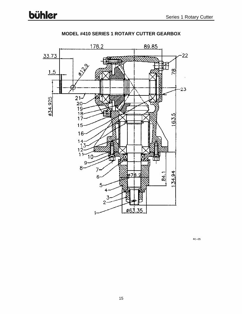
MODEL #410 SERIES 1 ROTARY CUTTER GEARBOX

Series 1 Rotary Cutter
16
MODEL #410 GEARBOX – SERIES 1
ITEM # PART # DESCRIPTION
814425 Gearbox Assembly 1 909785 Cotter Pin 5 x 45 2 909786 Blade Nut 3 909787 Washer - Blade Hub 4 909788 Blade Hub 5 909789 Shaft - Output 6 909790 Oil Seal 1.56 x 2.215 x 0.375 7 909791 Bolt - Output Cap 8 909792 Spring Washer 9 909793 Output Cap
10 909794 Gasket - Output Cap 11 909795 Housing 12 909796 Spacer - Bearing 13 909797 Retaining Ring - Output Shaft 14 909798 Bearing 6208 15 909799 Gasket - Input Cap 16 909800 Bearing 6207 17 909801 Input Cap 18 909802 Input Gear 19 909803 Retaining Ring - Input Shaft 20 909804 Oil Seal 1.35 x 2.215 x 0.375 21 909805 Input Shaft 22 909806 Vent Plug 23 909807 Pipe Plug 1/8"
Series 1 Rotary Cutter
17
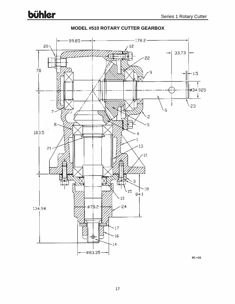
MODEL #510 ROTARY CUTTER GEARBOX

Series 1 Rotary Cutter
18
MODEL #510 GEARBOX – SERIES 1 & 2
ITEM # PART # DESCRIPTION 966108 Gearbox Assembly 1 914018 Housing 2 914006 Cap - Input 3 914015 Cap - Output 4 904022 Gear - Output, w/Shaft 15T 5 904021 Gear - Input 22T 6 966824 Shaft - Input 1 3/8" 7 966542 Bearing - Ball 207K 8 966555 Bearing - Ball 208K 9 914005 Seal - Input 3LIP
10 914013 Seal - Output 3LIP 11 914019 Gasket - Output Cap 12 914007 Gasket - Input Cap 13 914001 Spacer 14 966562 Cotter Pin 5 x 50 15 86171 3/8" x 1 1/4" Hex Bolt 16 967217 1" Slotted Hex Nut 17 904028 Washer - Blade Hub 1" 18 81593 3/8" Lockwasher 19 914016 1/8" Sq Head Pipe Plug 20 905429 1/2" Vent Plug 21 914008 Retaining Ring Eaton 916R 22 914003 Retaining Ring 23 966545 Snap Ring 24 904023 Blade Hub

Series 1 Rotary Cutter
19
SERIES 1 ROTARY CUTTER BUNDLES QUANTITY BUNDLE NO. DESCRIPTION MODEL #410 SERIES 1 ROTARY CUTTER (THREE POINT)- Y410LS
1 F0869 Deck Assembly MODEL #510 SERIES 1 ROTARY CUTTER (THREE-POINT)- Y510LS 1 F0870 Deck Assembly SERIES 1 ROTARY CUTTER OPTIONS OPTIONAL CHAIN KIT FOR Y410LS CUTTERS – Y424LS
1 F0878 Carton 1 F0877 Plates & Rods
OPTIONAL CHAIN KIT FOR Y510LS CUTTERS – Y524LS
1 F0876 Carton 1 F0875 Plates & Rods


Buhler Manufacturing “a partnership” 301 Mountain Street S. Morden MB. R6M 1X7 Ph.: (204) 822-4467 Fax: (204) 822-6348 www.buhler.com
Printed in Canada
Farm King Division 301 Mountain Street S. Morden, MB R6M 1X7 Ph.: (204) 822-4467 Fax: (204) 822-6348 Allied Division 1201 Regent Ave. W. Box 1003 Winnipeg, MB R2C 3B2 Ph.: (204) 661-8711 Fax: (204) 654-2503 Inland Division 675 Washington Ave. Winnipeg, MB R2K 1M4 Ph: (204) 667-7854 Fax: (204) 669-2599 B.I.I. Division 1330 43rd Street N.W. Fargo, ND 58102 Ph: (701) 282-7014 Fax: (701) 282-5865 B.C., Abbotsford (604) 864-2665 AB, Edmonton (403) 962-6991 SK, Regina (306) 781-2300 ON, Woodstock (519) 539-0435 ON, Jasper (613) 283-1758 QC, Dorion (450) 455-4840
AR, West Memphis (870) 732-3132
GA, Stone Mountain (770) 908-9439 IA, Lakeview (712) 657-8585 ID, Meridian (208) 887-6006
IN, Clarksville (812) 284-3376 KS, Wichita (316) 265-9577
MN, Lakeville (952) 469-5267
MT, Billings (406) 248-7771
Burando Hill Katanning W. Australia 011-618-98-214422 Chihuahua, Mexico
011-52-158-90306
ND, Bismarck (701) 223-1886 ND, Fargo (701) 282-7003 NY, Syracuse (315) 463-5276 OH, Youngstown (330) 793-0862 OR, Portland (503) 234-0378 SD, Huron (605) 352-8616 TX, Houston (713) 928-2632 UT, Salt Lake City (801) 972-4321 WI, Portage (608) 742-1370 John Kerr Equipment Ltd. Wilcoxholm Farm Linlithgow, W. Lothian Scotland 011-441-506-842280 Skovde, Sweden 011-46-500-452651 Naestved, Denmark 011-45-557-29511
CANADIAN WAREHOUSES
U.S. WAREHOUSES
OFFSHORE WAREHOUSES
DIVISION LOCATIONS