series 2000 reader system ascii protocol - ti.com · series 2000 reader system ascii protocol...
TRANSCRIPT

Series 2000 Reader SystemASCII Protocol
Reference Guide
May 2000
SCBU028

Series 2000 Reader System
ASCII Protocol
Reference Guide
Literature Number: SCBU028
May 2000

Contents
Preface ............................................................................................................................... 7
1 Introduction ............................................................................................................... 91.1 Product Description ............................................................................................... 10
1.1.1 Microcomputer Reset .................................................................................... 10
1.1.2 Transmit Function ........................................................................................ 10
1.2 Transponder Detection (RO, R/W, or MPT) ................................................................... 10
1.3 Data Handling...................................................................................................... 11
1.3.1 Data Check................................................................................................ 11
1.3.2 Data Buffer ................................................................................................ 11
1.3.3 Data Conversion.......................................................................................... 11
1.4 Handshake Mode.................................................................................................. 14
2 Commands .............................................................................................................. 152.1 Introduction......................................................................................................... 16
2.2 Reader Mode Commands........................................................................................ 16
2.2.1 64-bit Transponder Mode or K0 Mode ................................................................ 16
2.2.2 Multipage Transponder Mode or K1 Mode............................................................ 16
2.3 General Commands............................................................................................... 16
2.3.1 Version Command ....................................................................................... 17
2.3.2 FORMAT Command ..................................................................................... 17
2.3.3 CLEAR Command........................................................................................ 17
2.3.4 READOUT BUFFER Command........................................................................ 18
2.3.5 I/O STATUS Command ................................................................................. 18
2.3.6 SET OUTPUTS Command.............................................................................. 20
2.3.7 COMBINED Commands – SET OUTPUT and GET I/O Status .................................... 21
2.3.8 SET CHARGE PERIOD Command.................................................................... 24
2.4 64-Bit Transponder – K0 Mode.................................................................................. 25
2.4.1 EXECUTE Command.................................................................................... 25
2.4.2 GATE Mode ............................................................................................... 25
2.4.3 STORE Command ....................................................................................... 26
2.4.4 READ MEMORY Command ............................................................................ 27
2.4.5 RAM FILL Command .................................................................................... 27
2.4.6 NUMBER Command ..................................................................................... 28
2.4.7 LINE Function ............................................................................................ 28
2.4.8 NORMAL Mode/ESCAPE .............................................................................. 29
2.4.9 PROGRAM Command................................................................................... 29
2.4.10 ANTENNA Commands ................................................................................. 30
2.5 Multipage Transponder – K1 Mode ............................................................................. 31
2.5.1 EXECUTE Command.................................................................................... 33
2.5.2 LINE Function............................................................................................. 35
2.5.3 NORMAL Mode........................................................................................... 38
2.5.4 PROGRAM Command................................................................................... 39
2.5.5 LOCK PAGE Command ................................................................................. 41
2.5.6 ANTENNA Commands .................................................................................. 41
SCBU028–May 2000 Contents 3Submit Documentation Feedback

3 Possible Responses ................................................................................................. 453.1 Possible Reading Responses ................................................................................... 46
3.2 Possible Programming Responses in MPT Mode (K1) ...................................................... 47
4 Contents SCBU028–May 2000Submit Documentation Feedback

List of Tables
2-1 General Commands........................................................................................................ 162-2 Input Line Status ........................................................................................................... 192-3 Input Line Status ........................................................................................................... 192-4 Output Line Settings ....................................................................................................... 212-5 Port Specifier for H Command............................................................................................ 222-6 Logical Operation for H Command....................................................................................... 222-7 Port Value ................................................................................................................... 222-8 64-Bit Transponder Commands .......................................................................................... 252-9 Multipage Transponder Commands ..................................................................................... 322-10 Multiplexer I/O Lines 6 and 7 Configuration ............................................................................ 352-11 Multiplexer I/O Lines 4 and 5 Configuration ............................................................................ 352-12 Multiplexer I/O Lines 6 and 7 Configuration ............................................................................ 372-13 Multiplexer I/O Lines 4 and 5 Configuration ............................................................................ 37
SCBU028–May 2000 List of Tables 5Submit Documentation Feedback

List of Tables6 SCBU028–May 2000Submit Documentation Feedback

PrefaceSCBU028–May 2000
Read This First
Edition One – May 2000
This is the first edition of this manual, it describes the ASCII software protocol that can be used with theTIRIS™ Series 2000 Readers (RI-STU-MBxA, RI-STU-251B), and the Series 2000 Control Module(RI-CTL-MBxA).
About This Guide
This manual describes the ASCII protocol that can be used for communication between the TIRIS Series2000 readers (RI-STU-MBxA, RI-STU-251B) and Series 2000 control module (RI-CTL-MBxA) with RFM(we will refer to this as the reader from this point on) and a host system (we will refer to this as a PC fromthis point on). It describes the commands that can be used, together with their effect, and providesexamples of each of these commands.
Conventions
WARNINGA warning is used where care must be taken or a certain proceduremust be followed, in order to prevent injury or harm to your health.
CAUTION
This indicates information on conditions that must be met or a procedure thatmust be followed, which if not heeded, could cause permanent damage to theequipment or software.
Note: Indicates conditions that must be met or procedures that must be followed, to ensureproper functioning of any equipment or software.
Information:Indicates information that makes usage of the equipment or software easier.
If You Need Assistance
Application Centers are located in Europe, North and South America, the Far East and Australia to providedirect engineering support. For more information, please contact your nearest TIRIS Sales and ApplicationCenter. The contact addresses can be found on our home page: http://www.tiris.com
Trademarks
TIRIS, TI-RFid, and Tag-it are trademarks of Texas Instruments.
All other trademarks are the property of their respective owners.
SCBU028–May 2000 Read This First 7Submit Documentation Feedback

www.ti.com
Read This First8 SCBU028–May 2000Submit Documentation Feedback

Chapter 1SCBU028–May 2000
Introduction
This chapter will introduce you to the ASCII protocol. It explains the environment inwhich the protocol is used, system modes, functions, and how the different types oftransponder used by TIRIS™ systems are identified.
Topic .................................................................................................. Page
1.1 Product Description .................................................................. 101.2 Transponder Detection (RO, R/W, or MPT) ................................... 101.3 Data Handling ........................................................................... 111.4 Handshake Mode ...................................................................... 14
SCBU028–May 2000 Introduction 9Submit Documentation Feedback

www.ti.com
1.1 Product Description
1.1.1 Microcomputer Reset
1.1.2 Transmit Function
1.2 Transponder Detection (RO, R/W, or MPT)
Product Description
This is a simple protocol that you can use to send ASCII character commands to the reader. It is possibleto use a standard terminal emulator program to send ASCII commands. The ASCII protocol can only beused with RS232 or RS422.
TIRIS readers and control modules are equipped with a reset circuit which resets them after power-up andif a supply voltage break-down occurs. A built-in watch-dog function secures re-initialization should amicrocomputer malfunction happen. After each initialization the ASCII character STX (STX = 2dec),together with carriage return and line feed are transmitted via the serial interface. Any characters whichmay be transmitted before the STX character are random characters caused by power-on of the interfacecircuit and are not relevant.
The reader can operate in four different modes. In EXECUTE mode the reader triggers a single command.In NORMAL, LINE and GATE modes (GATE mode is only possible in K0) the read function is continuouslytriggered by the reader or control unit. The time between two readout cycles depends on the dataprocessing time and the duty cycle pause. While the RF Module is in the transmitting phase, the redACTIVE LED is activated.
The TIRIS readers and control modules are able to distinguish between three transponder types, they are:
Read Only = RO
Read/Write = R/W
Multipage = MPT
A character reflecting the transponder type is transmitted to the Computer (PC) within the serial protocol.The characters are: R for Read Only, W for Read/Write, and M for Multipage Transponders.
Examples:
Serial Protocol Comment
RO detected in NORMAL mode (K1)1R 0000 0000000120672337<CR><LF>
RO detected in NORMAL mode (K0)R 0000 0000000130655388<CR><LF>
R/W detected in LINE mode (K0)LW 0000 0000000013444555<CR><LF>
R/W detected in LINE mode (K1)L1W 0000 0000000013264565<CR><LF>
RO detected in EXECUTE mode (hexadecimal output format)X1R 0000AFC234567ABC<CR><LF>
MPT detected in LINE modeL10M 05 1234 1234123434567653<CR><LF>
MPT detected in EXECUTE mode (hexadecimal output format)X10M 11 FFFFFFFFFFFFFFFF<CR><LF>
Introduction10 SCBU028–May 2000Submit Documentation Feedback

www.ti.com
1.3 Data Handling
1.3.1 Data Check
1.3.2 Data Buffer
1.3.3 Data Conversion
Data Handling
A data check is always performed on the data signal received from the transponder.
Three different reading status are possible when attempting to read a transponder:
• Identification correctly received• Invalid Identification• No Identification detected (no read)
After addressing MPTs, however, the TIRIS reader sends out different protocols as described in sections3.1 and 3.2.
In all cases the following is true:
• If the identification number is correct, the green O.K. LED is activated.• If a transponder protocol could not be detected, or only a start byte could be detected the green O.K.
LED will not be activated.• In LINE or EXECUTE mode the ASCII character ' I ' will be sent to the PC if at least the start byte of a
transponder protocol could be detected.
Examples:
Serial Protocol Comment
TIRIS reader in LINE mode read correct R/W IDLW 0000 0000000023450607<CR><LF>
MPT detected in LINE modeL10M 05 1234 123412343456765<CR><LF>
TIRIS reader in EXECUTE read correct RO IDXR 0000 5674895692567054<CR><LF>
Reader in LINE mode (invalid ID)LI<CR><LF>
Reader in EXECUTE mode (invalid ID)XI<CR><LF>
Reader in LINE mode (no read)L<CR><LF>
Reader in EXECUTE mode (no read)X<CR><LF>
Note: In a noisy environment, it could occur that the invalid ID character is generated, evenwhen there is no transponder within the reading area.
In NORMAL mode (see 2.4.8 and 2.5.3), a correctly received identification number is transmitted via theserial interface only if it is different to the previously received transponder identification. The comparisonincludes the transponder type (RO, R/W or MPT), read page (if an MPT was read) and the identificationnumber.
For this purpose the last transponder information received is stored in an identification data buffer, locatedin the microcomputer RAM, and each correctly received information together with its transponder type[RO, R/W, and MPT (if in Multipage Transponder mode)] are compared to the content of this buffer. Thebuffer is cleared by a microcomputer reset or by the PC command CLEAR (2.3.3).
TIRIS Read Only transponders can be split into two groups with regard to their numbering system. Thesetwo groups are Animal Code numbers (according to ISO 11784/11785) described in section 1.3.3.2 andIndustrial (non-Animal) numbers described in section 1.3.3.1.
Read/Write and Multipage Transponders are not affected by the ISO 11784/11785 and are therefore onlyfor use with the Industrial numbering.
SCBU028–May 2000 Introduction 11Submit Documentation Feedback

www.ti.com
1.3.3.1 TIRIS Industrial Format
Data Handling
In the default decimal output format, when the most significant bit of the RO Transponder ID is 0 or for aR/W or Multipage Transponder, the 12 most significant bits of the 64-bit identification number areconverted into a 4-digit decimal application code (0000 to 4095). The least significant 52 bits of theidentification number are converted into a 16-digit decimal identification code (0000000000000000 to4503599627370495).
12 Introduction SCBU028–May 2000Submit Documentation Feedback

www.ti.com
LR 0127 4503599627370495 TIRIS decimal output format
| | |
| | |________ Identification Code
| |
| |_________________ Application Code
|
|_____________________ Indicator for a Industrial coded RO Transponder
(MSB of the Transponder ID is 0)
1.3.3.2 TIRIS Animal Format
Transponder number: 2048 0274603029037288D e c
Or 8000F9C0000000E8H e x
1000 0000 0000 0000 1111 1001 1100 0000 0000 0000 0000 0000 0000 0000 0000 1110 1000
8 0 0 0 F 9 C 0 0 0 0 0 0 0 0 E 8
MSB LSB
1 00000000000000 0 111110011 00000000000000000000000000000011101000
1 Bit 14 Bits 1 Bit 10 Bits 38 Bits
MSB LSB
Animalcoded
Trp. Flag
Reserved AdditionalData Flag
ISO 3166 numeric-3Country Code
National Identification Code
111110011B i n
00000000000000000000000000000011101000B i n
OR OR
3E7H e x
0000000E8H e x
OR OR
999D e c
232D e c
Data Handling
Indicator for an Industrial string in K0 Line mode:
For information about changing the output format to hexadecimal, see section 2.3.2 "FORMAT command".
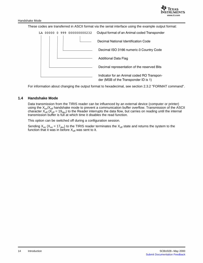
In decimal output format and when the most significant bit of a RO Transponder ID is 1 (Animal codedTransponder ID), the 64 bits of the ID are split into five fields, described by means of an ID examplebelow. An 'A' is always sent within the response string to indicate "Animal", instead of the 'R' to indicate aRO Transponder using the Industrial numbering.
Example:
The ID Split according to ISO 11784 is:
SCBU028–May 2000 Introduction 13Submit Documentation Feedback
www.ti.com
LA 00000 0 999 000000000232 Output format of an Animal coded Transponder
Decimal National Identification Code
Decimal ISO 3166 numeric-3 Country Code
Additional Data Flag
Decimal representation of the reserved Bits
Indicator for an Animal coded RO Transpon-
der (MSB of the Transponder ID is 1)
1.4 Handshake Mode
Handshake Mode
These codes are transferred in ASCII format via the serial interface using the example output format:
For information about changing the output format to hexadecimal, see section 2.3.2 "FORMAT command".
Data transmission from the TIRIS reader can be influenced by an external device (computer or printer)using the Xon/Xoff handshake mode to prevent a communication buffer overflow. Transmission of the ASCIIcharacter Xoff (Xoff = 19dec) to the Reader interrupts the data flow, but carries on reading until the internaltransmission buffer is full at which time it disables the read function.
This option can be switched off during a configuration session.
Sending Xon (Xon = 17dec) to the TIRIS reader terminates the Xoff state and returns the system to thefunction that it was in before Xoff was sent to it.
14 Introduction SCBU028–May 2000Submit Documentation Feedback

Chapter 2SCBU028–May 2000
Commands
This chapter describes the commands that can be sent to the reader or control modulefrom the controlling computer and the modes that the reader or control module canwork in.
Topic .................................................................................................. Page
2.1 Introduction.............................................................................. 162.2 Reader Mode Commands ........................................................... 162.3 General Commands................................................................... 162.4 64-Bit Transponder – K0 Mode ................................................... 252.5 Multipage Transponder – K1 Mode.............................................. 31
SCBU028–May 2000 Commands 15Submit Documentation Feedback

www.ti.com
2.1 Introduction
2.2 Reader Mode Commands
2.2.1 64-bit Transponder Mode or K0 Mode
2.2.2 Multipage Transponder Mode or K1 Mode
2.3 General Commands
Introduction
If a PC is connected to the interface, the transmitted application and identification codes can be stored,converted to other formats, displayed on the PC monitor or transferred to other equipment. In addition thePC can control the operation of the TIRIS reader by sending special command characters to it. All thecommands that can be sent from the PC to the TIRIS reader are described in the following sections. TheTIRIS reader accepts both upper and lower case command characters. In order to provide a uniform style,all examples we have given use upper-case command character.
All TIRIS transponder types fall into one of two groups of transponders: Multipage Transponders (MPTs)and 64-bit transponders (ROs and R/Ws). Since both of these transponder groups need differentprotocols, the TIRIS reader must be able to operate in two different modes.
The commands (and responses) that can be used with 64-bit transponders in the K0 mode are describedin section 2.4.
The commands (and their responses) that can be used with multipage transponders in the K1 mode aredescribed in section 2.5.
Note: The GATE mode for multipage transponders is not supported in K1 mode.
The commands that can be used in both modes (K0 and K1) are described in this section (2.3.1 to 2.3.8)these commands are listed in Table 2-1.
Table 2-1. General Commands
Character Command Section
B READOUT BUFFER Command 2.3.4
C CLEAR Command 2.3.3
F FORMAT Command 2.3.2
COMBINED CommandH 2.3.7SET OUTPUTS/GET I/O STATUS
J I/O Status Command 2.3.5
V VERSION Command 2.3.1
Y SET OUTPUTS Command 2.3.6
Z SET CHARGE PERIOD 2.3.8
Commands16 SCBU028–May 2000Submit Documentation Feedback

www.ti.com
2.3.1 Version Command
2.3.2 FORMAT Command
2.3.3 CLEAR Command
General Commands
The ASCII character V induces the TIRIS reader to transmit the version number of the software followedby carriage return and line feed.
Example:
PC --> Reader:
V
Reader --> PC:
S2500 - REV 1.1x<CR><LF>
Sending the ASCII character F to the TIRIS reader causes a change of the output format of page andidentification number from decimal to hexadecimal format.
The character F, carriage return and line feed will be transmitted by the TIRIS reader when thecommand is accepted. Each identification following this command is done in hexadecimal format until theESCAPE command is received.
It is now possible to set the hexadecimal format as the default format, using the TIRIS Reader Manager.
Note: Only the responses from the TIRIS reader to the PC are influenced by the FORMATcommand. The command format from the PC to the TIRIS reader must always be inhexadecimal format.
The FORMAT command can be used in the same way for both TIRIS reader modes (K0 and K1).
Example: Comment
PC --> Reader:
F Initiates Format – command
Reader --> PC:
F<CR><LF> All further identifications are transmitted inhexadecimal format
Reader --> PC:
X1R FFFFFFFFFFFFFFFF<CR><LF> K1 mode
XR FFFFFFFFFFFFFFFF<CR><LF> K0 mode
L10M 05 ABCFED672889AD38<CR><LF> K1 mode
R 0123456789ABCDEF<CR><LF> K0 mode
Regardless of the current transponder mode, the ASCII character C erases the identification buffer used inNORMAL mode and sets the ID counter used in GATE mode to zero. When this task has been performed,the TIRIS reader sends back the ASCII character C, carriage return and line feed.
The CLEAR command can be used in the same way for both TIRIS reader modes.
SCBU028–May 2000 Commands 17Submit Documentation Feedback

www.ti.com
2.3.4 READOUT BUFFER Command
2.3.5 I/O STATUS Command
General Commands
Example: Comment
PC --> Reader:
C Initiates Clear - command
Reader --> PC:
C<CR><LF>
The ASCII character B causes the TIRIS reader to transmit the ASCII character B and the content of thebuffer (used in NORMAL mode, see section 1.3.2) followed by carriage return and line feed to the PC. Ifthe buffer is empty, the TIRIS reader sends back the ASCII character B, carriage return and line feed.
Example: (ID is buffered) Comment
PC --> Reader:
B Initiates Readout Buffer - command
Reader --> PC:
B10M 01 0000 0000000000000001<CR><LF>
Example: (no ID is buffered)
PC --> Reader:
B
Reader --> PC:
B<CR><LF>
The ASCII character J causes the TIRIS reader to transmit the current status of the four lower I/O and thefour higher I/O lines. The result of this function depends on the configuration of the I/O port lines. Duringthe manufacturing process, the TIRIS reader is configured so that I/O lines 0 to 3 are set to input while I/Olines 4 to 7 are set to output. This configuration can be changed using the TIRIS Reader Manager, thenew setting is then used as default.
When the TIRIS reader receives the command character J it echoes it back to the PC together with twoASCII characters which represent the status of the input and output lines (hexadecimally coded) followedby carriage return and line feed.
The first character after the J represents the status of the I/O lines 0 to 3. Table 2-2 shows the relationshipbetween the character and the status of the lines.
Commands18 SCBU028–May 2000Submit Documentation Feedback

www.ti.com
General Commands
Table 2-2. Input Line Status (1)
Status of Status of Status of Status ofReturned Character I/O 3 I/O 2 I/O 1 I/O 0
0 0 0 0 0
1 0 0 0 1
2 0 0 1 0
3 0 0 1 1
4 0 1 0 0
5 0 1 0 1
6 0 1 1 0
7 0 1 1 1
8 1 0 0 0
9 1 0 0 1
A 1 0 1 0
B 1 0 1 1
C 1 1 0 0
D 1 1 0 1
E 1 1 1 0
F 1 1 1 1(1) 1 = Logical high, 0 = Logical low
The second character after J represents the status of the I/O lines 4 to 7. Table 2-3 shows the relationshipbetween the character and the status of the lines:
Table 2-3. Input Line Status
Status of Status of Status of Status ofReturned Character I/O 3 I/O 2 I/O 1 I/O 0
0 0 0 0 0
1 0 0 0 1
2 0 0 1 0
3 0 0 1 1
4 0 1 0 0
5 0 1 0 1
6 0 1 1 1
7 0 1 1 1
8 1 0 0 0
9 1 0 1 0
A 1 0 1 0
B 1 0 1 1
C 1 1 0 0
D 1 1 0 1
E 1 1 1 0
F 1 1 1 1
abc
Example Comment
PC --> Reader:
J Command character
Reader --> PC:
SCBU028–May 2000 Commands 19Submit Documentation Feedback

www.ti.com
2.3.6 SET OUTPUTS Command
General Commands
J2A<CR><LF> Input lines: I/O 0 = 0
I/O 1 = 1
I/O 2 = 0
I/O 3 = 0
Output lines: I/O 4 = 0
I/O 5 = 1
I/O 6 = 0
I/O 7 = 1
The ASCII character Y followed by an ASCII character in the range 0 to F causes the TIRIS reader toswitch four output lines. The way that this works depends on the configuration of the I/O port lines. Duringthe manufacturing process, the TIRIS reader is configured so that I/O lines 0 to 3 are set to input while I/Olines 4 to 7 are set to output and all the output lines are set to 1. This default configuration can bechanged to a customer specific configuration.
In order for this command to function correctly, a configuration that sets one of the I/O groups to output isrequired. This command reads the configuration information and sets the output level (0 or 1) of the I/Oswhich are configured to outputs.
If both groups of I/O lines are configured to output, only I/O lines 4 to 7 are set by the SET OUTPUTScommand. When both groups of I/O lines are configured to outputs you need to use the COMBINEDcommand (described in section 2.3.7).
If both groups of I/O lines are configured to input, the command will not have any effect.
The relationship between the number (0 to F) and the setting of the output lines is given in Table 2-4.
Commands20 SCBU028–May 2000Submit Documentation Feedback

www.ti.com
2.3.7 COMBINED Commands – SET OUTPUT and GET I/O Status
General Commands
Table 2-4. Output Line Settings (1)
Status of Status of Status of Status ofASCII Character I/O 7 I/O 6 I/O 5 I/O 4
0 0 0 0 0
1 0 0 0 1
2 0 0 1 0
3 0 0 1 1
4 0 1 0 0
5 0 1 0 1
6 0 1 1 0
7 0 1 1 1
8 1 0 0 0
9 1 0 0 1
A 1 0 1 0
B 1 0 1 1
C 1 1 0 0
D 1 1 0 1
E 1 1 1 0
F 1 1 1 1(1) 1 = Logical high, 0 = Logical low
Once the TIRIS reader has received the command character Y it echoes it to the PC in order to indicatethat the TIRIS reader is ready to receive a parameter (range: 0 to F) specifying the logic output level.Once the command has been executed the TIRIS reader sends carriage return and line feed back to thePC.
Note: In order to prevent the TIRIS reader from damage please take care not to exceed theElectrical Characteristics, given in the relevant manual.
Example: Comment
PC --> Reader:
Y Command character
Reader --> PC:
Y
Reader --> PC:
1 Output lines: I/O 4 = 1
I/O 5 = 0
I/O 6 = 0
I/O 7 = 0
Reader --> PC:
<CR><LF>
This command combines and extends the I/O STATUS command (2.3.5) and SET OUTPUTS command(2.3.6). Once the TIRIS reader has received the command character H it echoes it to the PC in order toindicate that the TIRIS reader is ready to receive further parameters specifying the operation to the I/Oports.
SCBU028–May 2000 Commands 21Submit Documentation Feedback

www.ti.com
General Commands
The following parameter (ASCII character) can either be:
I to specify get the status of input ports, followed by:
port specifier in the range of 0...4 (Table 2-5 lists the ports specified)
or
O to specify that outputs are to be set, followed by
port specifier in the range of 0...3 (Table 2-5 lists the ports specified)
logical operation in the range of 0...4 (Table 2-6 describes the logical operations)
port value two ASCII characters (Table 2-7 shows the port values)
If neither I or O follows the H command, or if the port specifier and the values for the logical operation areout of their range, carriage return and line feed are returned, and no action is performed. Table 2-5shows the assignment for the ports.
Table 2-5. Port Specifier for H Command
Port Specifier Description(ASCII Character)
0 Open Collector Outputs
1 I/O Port 0...7
2 I/O Port 0...3
3 I/O Port 4...7
4 IN 0/1
Table 2-6 shows the possible logical operations to write to an output. The port value is either writtendirectly to the output or the port status is read and a logical operation is performed with the port value, theresult of this operation is written back to the port.
Table 2-6. Logical Operation for H Command
Logical Operation Description(ASCII Character)
0 Port value is written directly to the output
1 Read status ANDed with port value
2 Read status ORed with port value
3 Read status XORed with port value
Read status is inverted (the port value is in this case4 meaningless)
Table 2-7 shows the value or status of the specified port.
Table 2-7. Port Value
Status or Port Value Description
00 to 03 Open Collector Outputs
00 to FF I/O Port 0 to 7
00 to 0F I/O Port 0 to 3
00 to 0F Port 4 to 7
00 to 03 (only status) IN 0/1
Commands22 SCBU028–May 2000Submit Documentation Feedback

www.ti.com
General Commands
xxx
Example 1 Comment
PC --> Reader:
H
Reader --> PC:
H
PC --> Reader:
I2 Get Input status of port lines 0...3
Reader --> PC:
03<CR><LF> Return Port status 0...3; in this example
I/O lines 0&1 of the I/O port 0...3 are set to 1
I/O lines 2&3 of the I/O port 0...3 are set to 0
xxx
Example 2 Comment
PC --> Reader:
H Assuming, Open Collector outputs were previously set to OC0=0and OC1=1
Reader --> PC:
H
PC --> Reader:
O0400 Invert current output settings of the Open Collector outputs. Theyare now set to OC0=1 and OC1=0
Reader --> PC:
<CR><LF>
xxx
Example 3 Comment
PC --> Reader:
H Assuming, I/O port lines 0...7 are configured to Output andpreviously set to 'A5'
Reader --> PC:
H
PC --> Reader:
O133F
Set outputs 0...7
Logical operation: XOR
Prior output status: A5
Port value: 3F
I/O 7 I/O 0 status
SCBU028–May 2000 Commands 23Submit Documentation Feedback

www.ti.com
2.3.8 SET CHARGE PERIOD Command
General Commands
1 0 1 0 0 1 0 1
XOR 0 0 1 1 1 1 1 1 port value
1 0 0 1 1 0 1 0 new output status
Reader --> PC:
<CR><LF>
Note: The result of the logical operation depends on the configuration of the I/O 0...7. The TIRISreader is preconfigured to:
I/O 0...3 INPUTI/O 4...7 OUTPUT all set to 1
This configuration can be changed, using the TIRIS Reader Manager.
The charge-up period to charge-up a transponder can be set in steps of 1 ms in the range: 15 ms to255 ms.
The ASCII character Z and two further ASCII characters (in the range of 0 to 9 and A to F) specify thecharge period. This hexadecimal number is translated into an actual time (for example: 32 = 50 ms,64 = 100 ms, and C8 = 200 ms), which will cause the TIRIS reader to change the charge period. This newcharge period is valid until the TIRIS reader is either reset or powered-up again. The default charge periodcan be set using the configuration utility software, but the charge period can still be modified using thiscommand.
If you try to set the charge period at less than 15 ms, the current charge period will not be changed.
Note: Changing the charge period has a great influence on the synchronization with otherreaders.
All Readers which should be synchronized must be configured with the same chargeperiod.
The TIRIS reader is preconfigured to 50 ms charge period.
Example: Comment
PC --> Reader:
Z
Reader --> PC:
Z
PC --> Reader:
20 Set charge period to 32 ms
20hex = 32dec
Reader --> PC:
<CR><LF>
Commands24 SCBU028–May 2000Submit Documentation Feedback

www.ti.com
2.4 64-Bit Transponder – K0 Mode
2.4.1 EXECUTE Command
2.4.2 GATE Mode
64-Bit Transponder – K0 Mode
The commands that can be used in the K0 mode for use with 64-bit transponders are described in thissection (2.4.1 to 2.4.9) these commands are listed in Table 2-8.
Table 2-8. 64-Bit Transponder Commands
Character Command Section
Esc NORMAL Mode/ESCAPE 2.5.3
G GATE Mode 2.4.2
L LINE Function 2.4.7
N NUMBER Command 2.4.6
P PROGRAM Command 2.4.9
R RAM FILL Command 2.4.5
S STORE Command 2.4.3
U ANTENNA Commands 2.4.10
X EXECUTE Command 2.4.1
? READ MEMORY Command 2.4.4
The ASCII character X switches the TIRIS reader to a single readout mode and triggers a single readoutsequence. After the readout the TIRIS reader is in an idle loop, waiting for the next command.
When an identification number is received and it is a valid number, the TIRIS reader transmits the ASCIIcharacter X, the transponder type character, space, 4-digit application code, space, 16-digitidentification code, carriage return and line feed to the PC. If the system does not read an identificationnumber, the ASCII character X (XI if the identification was not valid), carriage return and line feed aretransmitted.
Example: Comment
Reader --> PC:
XR 4095 4503599627370495<CR><LF> RO type correctly read
XW 2095 3453577809046784<CR><LF> R/W type correctly read
X<CR><LF> No read
XI<CR><LF> Invalid identification
In the GATE mode each correct identification number is compared with the identifications stored in theidentification memory. If the identification number is new, it is then stored in the identification memory.
The ASCII character G activates a continuous readout mode. The TIRIS reader confirms with the ASCIIcharacter G, carriage return and line feed. Each time that a new identification is stored in theidentification memory the ASCII character G, the transponder type character, space, the actualmemory count number, space, application code, space, identification code, carriage return and linefeed are transmitted via the interface.
When the identification is stored in location 909, the warning * MEMORY FULL, carriage return and linefeed are also transmitted to the PC. After the warning the GATE mode is still active but no moreidentifications are transmitted to the PC.
When GATE mode is selected the K command is disabled as it is not possible to have GATE mode inMultipage transponder mode.
SCBU028–May 2000 Commands 25Submit Documentation Feedback

www.ti.com
2.4.3 STORE Command
64-Bit Transponder – K0 Mode
Example:
PC --> Reader:
G
Reader --> PC:
G<CR><LF>
GR 001 4095 4503599627370495<CR><LF>
GM 400 3033 1324364758692037<CR><LF>
GW 909 2047 2345678901234567<CR><LF>
* MEMORY FULL<CR><LF>
The ASCII character S causes transmission of all stored identification numbers from the memory to thePC together with the memory location where the identification number is stored. Each transmitted lineconsists of the transponder type character, space, the memory location, space, application code,space, identification code, carriage return and line feed. For hexadecimal format refer to thedescription of the FORMAT command earlier in this section.
When the transmission has been completed the TIRIS reader transmits the ASCII character S, carriagereturn and line feed. As described in section 1.4, the transmission of this data can be influenced byXon/Xoff (if enabled).
Commands26 SCBU028–May 2000Submit Documentation Feedback

www.ti.com
2.4.4 READ MEMORY Command
2.4.5 RAM FILL Command
64-Bit Transponder – K0 Mode
Example: (three ID's are stored)
PC --> Reader:
S
Reader --> PC:
R 001 4095 4503599627370495<CR><LF>
W 002 0000 0000000000000001<CR><LF>
M 003 0000 0000000000212121<CR><LF>
S<CR><LF>
The ASCII character ? causes the TIRIS reader to confirm the character ?. Entering the memory location(three characters are necessary) then causes the TIRIS reader to transmit space, the memory location,space, the 16 digit identification code, the transponder type information (the last two digits), carriagereturn and line feed.
Example: Comment
PC --> Reader:
?
Reader --> PC:
?
PC --> Reader:
38D Only in hexadecimal
Reader --> PC: (memory location 909dec=38Dhex)
<space>38D 0123456789ABCDEF00<CR><LF> Only in hexadecimal
As previously said, the last two digits (17 and 18) contain the transponder type information. In fact digit 18carries the information as digit 17 is always 0. The information is carried as follows:
Digit 17 Digit 18
BINARY: 0000 0000 RO
0000 0001 R/W
0000 0010 MPT
Note: The TIRIS reader acknowledges receipt of the Read Memory command by echoing thecommand character to indicate that it is ready to receive further data.
The PC can check the memory by filling it with a pattern and then reading the memory to see if thispattern is in each of the memory locations.
Note: This memory test overwrites all the existing memory contents. This means that all prior IDnumbers stored in the memory are lost and the ID counter will be set to 909dec = 38Dhex.
SCBU028–May 2000 Commands 27Submit Documentation Feedback

www.ti.com
2.4.6 NUMBER Command
2.4.7 LINE Function
64-Bit Transponder – K0 Mode
The ASCII character R and two ASCII characters (in the range 0 to 9 and A to F) which specify an 8 bittest pattern in hexadecimal format causes the identification memory locations to be loaded with thispattern. All three characters are confirmed separately to the PC. After the identification memory is filled,the TIRIS reader transmits the ASCII character R, carriage return and line feed. It is now possible tocheck whether all cells are correctly filled by using the STORE command.
Example: Comment
PC --> Reader: (pattern = 01011010BIN = 5Ahex):
R RAM FILL command
PC --> Reader:
R RAM FILL command confirmed
PC --> Reader:
5 First HEX character of 5Ahex = 01011010bin
Reader --> PC:
5 First HEX character confirmed
PC --> Reader:
A Second HEX character of 5Ahex = 01011010bin
Reader --> PC:
AR<CR><LF> Second HEX character and RAM FILL execution confirmed
The number of stored identifications can be checked by the PC sending the ASCII character N to theTIRIS reader. It causes the TIRIS reader to transmit the ASCII character N, space, the number ofidentifications stored in the memory in hexadecimal format, carriage return and line feed via theinterface.
Example:
PC --> Reader:
N
Reader --> PC: (909dec =38Dhex identifications stored)
N 38D<CR><LF>
The ASCII character L switches the TIRIS reader into a special continuous readout mode. In this modeeach correct identification causes the direct transmission of the ASCII character L, the transponder typecharacter, space, application code, space, identification code, carriage return and line feed withoutbuffer comparison.
If no identification is received or if the identification is not valid, the ASCII character L together with anoptional I, carriage return and line feed are transmitted.
Example:
PC --> Reader:
L
Reader --> PC:
28 Commands SCBU028–May 2000Submit Documentation Feedback

www.ti.com
2.4.8 NORMAL Mode/ESCAPE
2.4.9 PROGRAM Command
64-Bit Transponder – K0 Mode
LR 4095 4503599627370495<CR><LF> RO type correctly read
LR 4095 4503599627370495<CR><LF> RO type correctly read
LI<CR><LF> Invalid identification
LI<CR><LF> Invalid identification
LW 2095 3453577809046784<CR><LF> R/W type correctly read
.
.
The NORMAL readout function provides a continuous readout of transponders at high speed. In this modeeach valid ID code and the transponder type, that is read in is compared to the identification which isalready in the buffer. If the identification is new it overwrites the buffer and is then transmitted to the PC.The transfer consists of the transponder type character, space, application code, space,identification code, carriage return and line feed.
The ASCII character Esc (Esc = 27dec) activates the NORMAL readout function. The ASCII character E,carriage return and line feed are returned by the TIRIS reader.
The NORMAL mode can be terminated by the commands EXECUTE, LINE or GATE. These commandsare all described in this section.
Example: Comment
PC --> Reader:
<Esc> Esc = 27dec
Reader --> PC:
E<CR><LF>
R 4095 4503599627370495<CR><LF> RO type correctly read
In order to program a Read/Write transponder the PC must first send the character P to the TIRIS readerand then when the character is echoed, the PC must transmit the 16 hexadecimal characters whichspecify the identification number to be programmed into the transponder. As soon as the TIRIS reader hasreceived the sixteenth character it calculates a Block Check Character (BCC). The transponder is thencharged-up, and the identification data including the BCC and some additional data are sent to thetransponder.
Once the programming cycle is completed, the transponder sends the newly programmed number back tothe TIRIS reader for comparison. After comparison the TIRIS reader sends a status character (0, 1, or 2)carriage return and line feed back to the PC. The meaning of the status characters is:
0 – The transponder has been correctly programmed.1 – The identification received from the transponder is different to the identification transmitted.2 – The TIRIS reader did not receive any identification from the transponder for comparison
Because the programming cycle is longer than the normal reading cycle, the TIRIS reader duringprogramming could interfere with other Readers in the area, even if they have been synchronized.
The distance over which the transponder can be programmed is less than the reading distance. This isdue to the higher power consumption of the transponder's IC during programming. If the transponder isnot sufficiently charged-up, the programming will not take place.
SCBU028–May 2000 Commands 29Submit Documentation Feedback

www.ti.com
2.4.10 ANTENNA Commands
2.4.10.1 ANTENNA 1 Mode
64-Bit Transponder – K0 Mode
Example:
PC --> Reader:
P
Reader --> PC:
P
PC --> Reader:
FEDCBA9876543210 The hexadecimal number that must be programmed into thetransponder
Reader --> PC:
0<CR><LF> Successful programming
or
1<CR><LF> Received identification is different to transmitted identification
or
2<CR><LF> No read
Note: If more than one transponder are in the field of the antenna it could happen that they areall programmed with the same number. If this happens and more than one transponderreturn the same identification at the same time (or the transmission is corrupted) theTIRIS reader will indicate that the programming failed even though at least onetransponder was correctly programmed.
The ASCII character U and a subsequent character 0 to 2 enable you to address a specific receive onlyantenna to be used.
Note: This command is only applicable to the S2000 reader with RFM-104B.
The following modes can be specified:1 = ANTENNA 12 = ANTENNA 20 = TOGGLE MODE
If the character U is followed by a character other than 0,1, or 2, the entire command will be ignored. Bothcommand characters will separately be echoed by the reader. The command acknowledgment iscompleted with the transmission of carriage return and line feed.
Note: The antenna addressing can be changed any time during continuous reading (NORMALmode (2.4.8), LINE mode (2.4.7) and GATE mode (2.4.2)).
The ASCII character U and the character 1 cause receive antenna 1 to be connected. In this mode eachcorrect identification read by antenna 1 is directly transferred to the PC.
Commands30 SCBU028–May 2000Submit Documentation Feedback

www.ti.com
2.4.10.2 ANTENNA 2 Mode
2.4.10.3 TOGGLE Mode
2.5 Multipage Transponder – K1 Mode
Multipage Transponder – K1 Mode
Example: Comment
PC --> Reader:
U Initiates Antenna mode – command
Reader --> PC:
U
PC --> Reader:
1 Switch to antenna 1
Reader --> PC:
1<CR><LF>
Switching to antenna 2 requires the command U2 instead of U1. Apart from the antenna specifier (thenumber 2 to specify antenna 2) the response format of the reader is exactly the same as described in2.4.10.1.
The ASCII character U and the character 0 switch the reader into a special antenna toggle mode. In thismode, both receive antennas (antenna 1 and antenna 2) are used consecutively. Thus, two reading cyclesare carried out compared to the ANTENNA 1 mode or ANTENNA 2 mode. The protocol sent out by thereader corresponds to the ANTENNA 1 mode (2.4.10.1) and ANTENNA 2 mode (2.4.10.2).
Note: When the reader is operating in the TOGGLE mode, the response to the Programmingcommand (2.4.9) is only checked at antenna 1.
Example: Comment
PC --> Reader:
U Initiates Antenna mode - command
Reader --> PC:
U
PC --> Reader:
0 Select antenna toggle mode
Reader --> PC:
0<CR><LF>
The commands that can be used in the K1 mode for use with MPTs are described in sections 2.5.1 to2.5.5 these commands are:
SCBU028–May 2000 Commands 31Submit Documentation Feedback

www.ti.com
Multipage Transponder – K1 Mode
Table 2-9. Multipage Transponder Commands
Character Command Section
Esc NORMAL Mode/ESCAPE 2.5.3
L (1) LINE Function 2.5.2
O LOCK PAGE Command 2.5.5
P PROGRAM Command 2.5.4
U ANTENNA Commands 2.5.6
X (1) EXECUTE Command 2.5.1(1) If the second character in the Execute and Line commands is M, the reader or control module is
switched to Multiplexer mode (2.5.2.1 or 2.5.2.2).
In order to address an MPT it is necessary to switch the TIRIS reader into the Multipage Transpondermode (K1 mode). The Multipage Transponder mode causes the TIRIS reader on the one hand to generatea protocol including additional information specifying the MPT page as well as information concerning thedesired command (PC --> TIRIS reader), and on the other hand to provide a status information (TIRISreader --> PC) to inform you which command was actually carried out in the transponder.
The ASCII character K and a subsequent character 1 enable you to switch into the Multipage Transpondermode. If character K is followed by a character other than 1 (MPT mode) or 0 (64-bit Transponder mode),the TIRIS reader will ignore the entire command. Both command characters will be separately echoed bythe TIRIS reader. The command acknowledgment is completed with the transmission of carriage returnand line feed.
Note: If the TIRIS reader is switched from the Multipage Transponder mode (K1) into the 64-bitTransponder mode (K0), continuous read-out functions NORMAL and LINE MODE keeprunning (for example: Line mode (K1) ---> Line mode (K0)).
If the TIRIS reader is switched from the 64-bit Transponder mode (K0) into the MultipageTransponder mode (K1) and continuous read-out functions were active, the TIRIS readerwill ask for additional two characters to specify the page of the MPT to be read, and thencontinue to run in the previous read mode.
Example (switching from 64-bit transponder functions to MPT functions):
PC --> Reader:
K Initiates Change mode - command
Reader --> PC:
K
PC --> Reader:
1
Reader --> PC:
1 <CR><LF> Command acknowledgment
When the command is acknowledged the TIRIS reader has been switched into the Multipage Transpondermode and is now ready to accept further command characters as described in sections 2.5.1 to 2.5.5.
Note: RO and R/W transponders can also be read when the TIRIS reader is operating in theMPT mode. If a RO or R/W is read when the TIRIS reader is in K1 (MPT) mode, anadditional character (antenna character) is transferred via the serial port immediatelybefore the transponder type character (R or W).
Commands32 SCBU028–May 2000Submit Documentation Feedback

www.ti.com
2.5.1 EXECUTE Command
2.5.1.1 Execute Command
Multipage Transponder – K1 Mode
If the command X is immediately followed by a page number (in the range 01 to 11) the system reads thespecified page as described in section 2.5.1.1. If the command X is immediately followed by the letter Mthe system is switched into Multiplexer mode as described in section 2.5.1.2.
The ASCII character X and a subsequent two digit page information, specifying the corresponding MPTpage (01 to 11hex) to be read, switch the TIRIS reader to a single readout mode and trigger one readoutsequence. This command can also be used to stop (terminate) the continuous read modes (LINE orNORMAL). After receiving the character X the TIRIS reader echoes X and waits for the page specification.After receiving the page specification the TIRIS reader proceeds with the EXECUTE command.
If no valid identification number could be received, the TIRIS reader transmits the antenna number, anoptional ' 11 ' (invalid), carriage return with line feed.
If an MPT transponder was read, the MULTIPAGE TRANSPONDER PROTOCOL, that is: antennanumber, status information, the transponder type character (M), space, transponder page read,space, application code, space, identification code, carriage return and line feed, will be transmittedto the PC.
If a RO or R/W was read, the TIRIS reader will transmit the 64-Bit PROTOCOL, that is: antenna number,transponder type character (R, W), space, application code, space, identification code, carriagereturn and line feed.
Note: Page specification 00 does not refer to an addressed page number 00, but just causesthe TIRIS reader to send a charge-up signal. This causes a simple read-out of the firstpage (01) of an MPT, or a read-out of a RO or R/W. Therefore if you only want to readpage 01 of an MPT you achieve a faster reading cycle time by specifying page 00.
Example: Comment
PC --> Reader:
X Initiates Execute - command
Reader --> PC:
X
PC --> Reader:
01 Page information in hexadecimal format
Reader --> PC: Only one of the following responses is possible:
10M 01 4095 4503599627370495<CR><LF> Correct MPT identification in decimal format
10M 01 FFFFFFFFFFFFFFFF<CR><LF> Correct MPT identification in hexadecimal format
1R 4095 4503599627370495<CR><LF> RO was read in decimal format
1W FFFFFFFFFFFFFFFF<CR><LF> R/W was read in hexadecimal format
1<CR><LF> No read
1I<CR><LF> Invalid identification
For further descriptions of possible command response formats see Chapter 3: "Possible ReadingResponses".
SCBU028–May 2000 Commands 33Submit Documentation Feedback

www.ti.com
2.5.1.2 Execute Command with TX/RX Multiplexer Support
Multipage Transponder – K1 Mode
Note: This command should only be used if you have the Remote Antenna RFM(RI-RFM-008B) and the Multiplexer Module (RI-MOD-TX8A) included in your system.
If the character immediately following X is M, the system is switched into the Transmit/ ReceiveMultiplexer mode. Following the M character four further parameters (characters) are required. Theyspecify (in the order they are transmitted to the reader):
• the number of Transmit Multiplex Antennas (TX_Ant)• the number of Receive Multiplex Antennas (RX_Ant)• the page information to read a Multipage Transponder (two digits; most significant digit of the page
first).
The range for TX_Ant and RX_Ant is 1 to 4. If the Multiplexer parameter are out of range, the Executecommand is executed with the default one Transmit Antenna and one Receive Antenna.
Examples:1. The command sequence 'X01' reads page 1 of a Multipage Transponder without switching the TX/RX
control outputs.2. The command sequence 'XM4201' reads page 1 of a Multipage Transponder, switching the control
output lines for a 4 Channel Transmit Multiplexer and a 2 Channel Receive Multiplexer.
A typical Multiplexer read sequence selects the Transmit Antennas from 1 to TX_ANT then the ReceiveAntennas are selected from 1 to RX_ANT with a successive transponder read.
The multiplexer sequence depends on how many transmit and receive antennas are specified, but thesequence is always: The first TX antenna is selected, then in series the RX antennas (1, 2, 3, or 4), thenthe next TX antenna is selected, followed once again by the RX antennas. Then the next TX antenna andso on.
Example: Comment
Read page 7 of a multipage transponder using 2 TXXM2407
and 4 RX antennas.
Sequence = TX Antenna 1 Read page 7
RX Antenna 1 Page 7 ID
RX Antenna 2 Page 7 ID
RX Antenna 3 Page 7 ID
RX Antenna 4 Page 7 ID
TX Antenna 2 Read page 07
RX Antenna 1 Page 7 ID
RX Antenna 2 Page 7 ID
RX Antenna 3 Page 7 ID
RX Antenna 4 Page 7 ID
Read page 9 of a multipage transponder using 2 TXXM2209
and 2 RX antennas.
Sequence = TX Antenna 1 Read page 9
RX Antenna 1 Page 9 ID
RX Antenna 2 Page 9 ID
TX Antenna 2 Read page 9
RX Antenna 1 Page 9 ID
34 Commands SCBU028–May 2000Submit Documentation Feedback

www.ti.com
2.5.2 LINE Function
Multipage Transponder – K1 Mode
RX Antenna 2 Page 9 ID
In order for the multiplexer to work correctly the I/O lines must be configured to be outputs (the defaultstatus).
Table 2-10. Multiplexer I/O Lines 6 and 7Configuration
External RX Mux.RX_Ant
I/O 6 I/O 7
1 0 0
2 1 0
3 0 1
4 1 1
The TX Multiplexer Channel is controlled with I/O line 4 and 5 according to the table below.
Table 2-11. Multiplexer I/O Lines 4 and 5Configuration
External RX Mux.TX_Ant
I/O 4 I/O 5
1 0 0
2 1 0
3 0 1
4 1 1
The response data format is defined as follows:
K1 Mode (1)
Read StatusCurrent Protocol Protocol for TX/RX Mux.
RO, R/W Trp. Xrx iiii iiiiiiiiiiiiiiii Xtrx iiii iiiiiiiiiiiiiiii
MPT Xrsx pp iiii iiiiiiiiiiiiiiii Xtrsx pp iiii iiiiiiiiiiiiiiii
incomplete ID XrI XtrI
no read Xr Xtr(1) X is the leading character to define the read mode
pp = Page of an MPTI = Transponder IDx = Transponder Typer = Receive antennat = Transmit antennas = read/programming status
Note: The receive multiplexer is only supported by TIRIS readers which include the RFM 104B.To ensure that other TIRIS readers function correctly, the Rx Antenna specifier must beset to 1.
If the command L is immediately followed by a page number (in the range 01 to 11) the systemcontinuously reads the specified page as described in section 2.5.2.1. If the command L is immediatelyfollowed by the letter M the system is switched into Multiplexer mode as described in section 2.5.2.2.
SCBU028–May 2000 Commands 35Submit Documentation Feedback
www.ti.com
2.5.2.1 Line Function
Multipage Transponder – K1 Mode
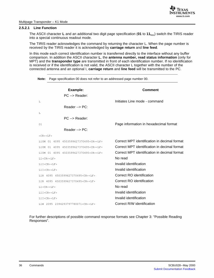
The ASCII character L and an additional two digit page specification (01 to 11hex) switch the TIRIS readerinto a special continuous readout mode.
The TIRIS reader acknowledges the command by returning the character L. When the page number isreceived by the TIRIS reader it is acknowledged by carriage return and line feed.
In this mode each correct identification number is transferred directly to the interface without any buffercomparison. In addition the ASCII character L, the antenna number, read status information (only forMPT) and the transponder type are transmitted in front of each identification number. If no identificationis received or if the identification is not valid, the ASCII character L together with the number of theconnected antenna and an optional I, carriage return and line feed will be transmitted to the PC.
Note: Page specification 00 does not refer to an addressed page number 00.
Example: Comment
PC --> Reader:
L Initiates Line mode - command
Reader --> PC:
L
PC --> Reader:
01 Page information in hexadecimal format
Reader --> PC:
<CR><LF>
L10M 01 4095 4503599627370495<CR><LF> Correct MPT identification in decimal format
L10M 01 4095 4503599627370495<CR><LF> Correct MPT identification in decimal format
L10M 01 4095 4503599627370495<CR><LF> Correct MPT identification in decimal format
L1<CR><LF> No read
L1I<CR><LF> Invalid identification
L1I<CR><LF> Invalid identification
L1R 4095 4503599627370495<CR><LF> Correct RO identification
L1R 4095 4503599627370495<CR><LF> Correct RO identification
L1<CR><LF> No read
L1I<CR><LF> Invalid identification
L1I<CR><LF> Invalid identification
L1W 2095 2394293797780071<CR><LF> Correct R/W identification
For further descriptions of possible command response formats see Chapter 3: "Possible ReadingResponses".
Commands36 SCBU028–May 2000Submit Documentation Feedback

www.ti.com
2.5.2.2 Line Function with TX/RX Multiplexer Support
Multipage Transponder – K1 Mode
Note: This command should only be used if you have a Multiplexer Module (RI-MOD-TX8A)included in your system.
If the character immediately following L is M, the system is switched into the Transmit/ Receive Multiplexermode. Following the M character four further parameters (characters) are required. They specify (in theorder they are transmitted to the reader):
• The number of Transmit Multiplex Antennas (TX_Ant)• The number of Receive Multiplex Antennas (RX_Ant)• The page information to read a Multipage Transponder (two digits; most significant digit of the page
first).
The range for TX_Ant and RX_Ant is 1 to 4. If the Multiplexer parameter are out of range, the Line modeis executed with the default one Transmit Antenna and one Receive Antenna.
Examples:1. The command sequence 'L01' reads page 1 of a Multipage Transponder continuously without
switching the TX/RX control outputs.2. The command sequence 'LM4201' continuously reads page 1 of a Multipage Transponder, switching
the control output lines for a 4 Channel Transmit Multiplexer and a 2 Channel Receive Multiplexer.
A typical Multiplexer read sequence selects the Transmit Antennas from 1 to TX_ANT then the ReceiveAntennas are selected from 1 to RX_ANT with a successive transponder read.
In order for the multiplexer to work correctly the I/O lines must be configured to be outputs (the defaultstatus).
Table 2-12. Multiplexer I/O Lines 6 and 7Configuration
External RX Mux.RX_Ant
I/O 6 I/O 7
1 0 0
2 1 0
3 0 1
4 1 1
The TX Multiplexer Channel is controlled with I/O line 4 and 5 according to the table below.
Table 2-13. Multiplexer I/O Lines 4 and 5Configuration
External RX Mux.TX_Ant
I/O 4 I/O 5
1 0 0
2 1 0
3 0 1
4 1 1
The response data format is defined as follows:
SCBU028–May 2000 Commands 37Submit Documentation Feedback

www.ti.com
2.5.3 NORMAL Mode
Multipage Transponder – K1 Mode
K1 Mode (1)
Read StatusCurrent Protocol Protocol for TX/RX Mux.
RO, R/W Trp. Lrx iiii iiiiiiiiiiiiiiii Ltrx iiii iiiiiiiiiiiiiiii
MPT Lrsx pp iiii iiiiiiiiiiiiiiii Ltrsx pp iiii iiiiiiiiiiiiiiii
incomplete ID LrI LtrI
no read Lr Ltr(1) L is the leading character to define the read mode
pp = Page of an MPTI = Transponder IDx = Transponder Typer = Receive antennat = Transmit antennas = read/programming status
Note: The receive multiplexer is only supported by TIRIS readers which include an RFM 104B.To ensure that other TIRIS readers function correctly, the Rx Antenna specifier must beset to 1.
The NORMAL readout function provides a continuous readout of a certain transponder page at highspeed. The transmission of a page including its identification via the serial interface will only be carried outif it is not equal to the last received transponder type (RO, R/W, and MPT), transponder page andidentification. For this purpose the last page received, together with its identification number is stored in anidentification buffer, located in the microcomputer RAM, and each correctly received page, identificationnumber and the transponder type (RO, R/W, MPT) is compared to the content of this buffer.
The NORMAL mode can also be used to terminate the LINE mode and to switch to decimal display if theFORMAT command was previously used.
ASCII character Esc (Esc=27dec) together with a page specification (01 to 11hex) cause the TIRIS readerto switch into the NORMAL mode. The ASCII character E, carriage return and line feed are returned bythe TIRIS reader in order to acknowledge the PC command.
Each received identification that is different to the identification stored in the buffer will be transmitted tothe PC:
If an MPT was read: antenna number, read status, transponder type character (M), space, page,space. application code, space, identification code, carriage return and line feed.
If a RO or R/W was read, the TIRIS reader will transmit the 64-bit PROTOCOL, that is: antenna number,transponder type character (R, W), space, application code, space, identification code, carriagereturn and line feed.
The NORMAL mode can be terminated by the commands EXECUTE (2.4.1) or LINE (2.4.7).
Note: Page specification 00 does not refer to an addressed page number 00.
Example: Comment
PC --> Reader:
<Esc> Initiates Normal mode - command,Esc=27dec
Reader --> PC:
E
PC --> Reader:
38 Commands SCBU028–May 2000Submit Documentation Feedback
www.ti.com
2.5.4 PROGRAM Command
Multipage Transponder – K1 Mode
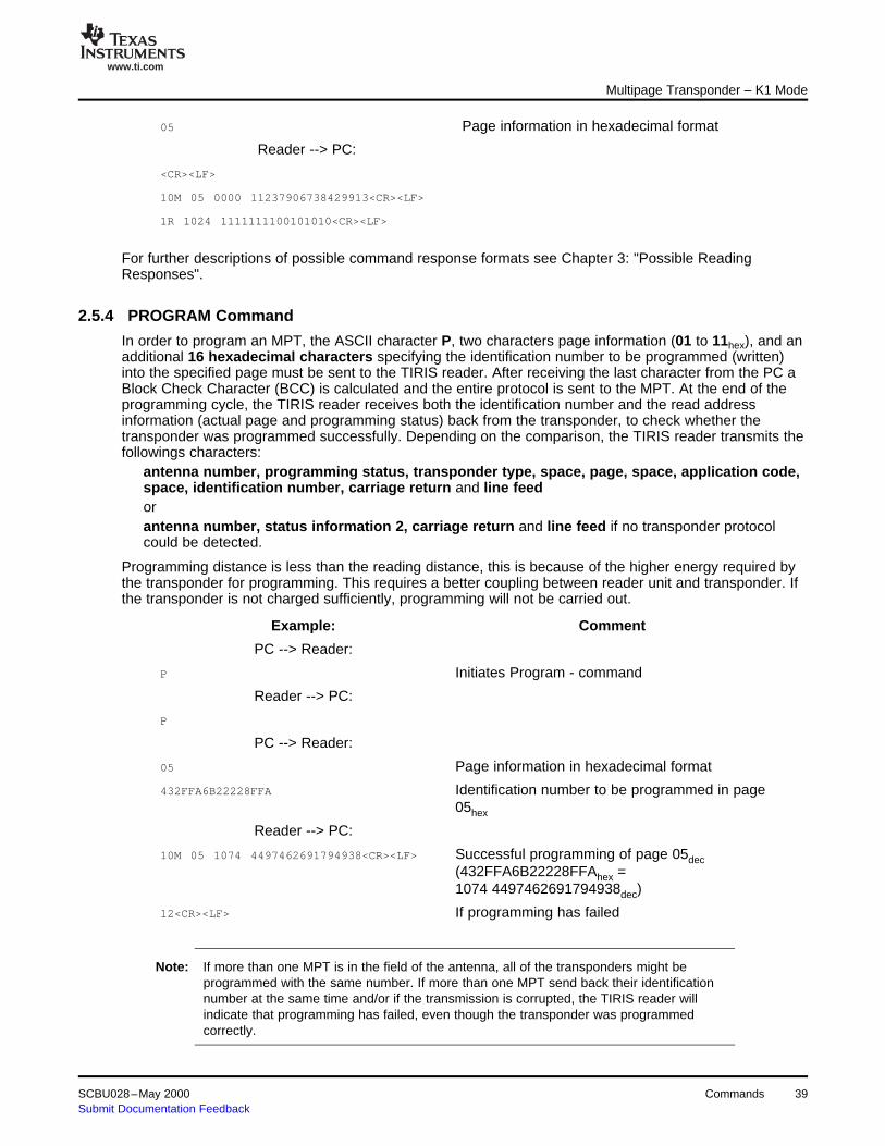
05 Page information in hexadecimal format
Reader --> PC:
<CR><LF>
10M 05 0000 11237906738429913<CR><LF>
1R 1024 1111111100101010<CR><LF>
For further descriptions of possible command response formats see Chapter 3: "Possible ReadingResponses".
In order to program an MPT, the ASCII character P, two characters page information (01 to 11hex), and anadditional 16 hexadecimal characters specifying the identification number to be programmed (written)into the specified page must be sent to the TIRIS reader. After receiving the last character from the PC aBlock Check Character (BCC) is calculated and the entire protocol is sent to the MPT. At the end of theprogramming cycle, the TIRIS reader receives both the identification number and the read addressinformation (actual page and programming status) back from the transponder, to check whether thetransponder was programmed successfully. Depending on the comparison, the TIRIS reader transmits thefollowings characters:
antenna number, programming status, transponder type, space, page, space, application code,space, identification number, carriage return and line feedorantenna number, status information 2, carriage return and line feed if no transponder protocolcould be detected.
Programming distance is less than the reading distance, this is because of the higher energy required bythe transponder for programming. This requires a better coupling between reader unit and transponder. Ifthe transponder is not charged sufficiently, programming will not be carried out.
Example: Comment
PC --> Reader:
P Initiates Program - command
Reader --> PC:
P
PC --> Reader:
05 Page information in hexadecimal format
432FFA6B22228FFA Identification number to be programmed in page05hex
Reader --> PC:
10M 05 1074 4497462691794938<CR><LF> Successful programming of page 05dec(432FFA6B22228FFAhex =1074 4497462691794938dec)
12<CR><LF> If programming has failed
Note: If more than one MPT is in the field of the antenna, all of the transponders might beprogrammed with the same number. If more than one MPT send back their identificationnumber at the same time and/or if the transmission is corrupted, the TIRIS reader willindicate that programming has failed, even though the transponder was programmedcorrectly.
SCBU028–May 2000 Commands 39Submit Documentation Feedback

www.ti.com
Multipage Transponder – K1 Mode
For a more precise overview of possible responses refer to Chapter 3: "Possible Programming Responsesin MPT mode".
Commands40 SCBU028–May 2000Submit Documentation Feedback

www.ti.com
2.5.5 LOCK PAGE Command
2.5.6 ANTENNA Commands
Multipage Transponder – K1 Mode
The LOCK Page command enables you to make a certain page of an MPT inaccessible to programming.ASCII character O initiates the LOCK page procedure. The TIRIS reader echoes the character as anacknowledgment and is now ready to accept the page to be locked (01 to 11hex). The following tworesponse formats from the TIRIS reader are possible after trying to lock a transponder page:
Antenna number, status, transponder type, space, page, space, application code, space,identification number, carriage return and line feed if a transponder protocol could be receivedorantenna number, optional I, carriage return and line feed if no valid transponder response could bedetected by the TIRIS reader.
Status 1 (read locked page) in the Multipage transponder protocol provides you with information about asuccessful locking of the page.
Example: Comment
PC --> Reader:
O Initiates Lock - command
Reader --> PC:
O
PC --> Reader:
05 Page information in hexadecimal format
Reader --> PC:
11M 05 1074 4497462691794938<CR><LF> Successful locking of page 05, displayed indecimal format
1<CR><LF> Command not executed
Note: If more than one MPT is in the field of the antenna, all of the transponders might beprogrammed with the same number. If more than one MPT send back their identificationnumber at the same time and/or if the transmission is corrupted, the TIRIS reader willindicate that programming has failed, even though the transponder was programmedcorrectly.
For a more precise overview of possible responses refer to Chapter 3: "Possible Reading Responses".
The ASCII character U and a subsequent character 0 to 2 enable you to address a specific receive onlyantenna to be used. The following modes can be specified:
Note: This command is only applicable to the S2000 reader with RFM-104B.
1 = ANTENNA 12 = ANTENNA 20 = TOGGLE MODE
If the character U is followed by a character other than 0,1 or 2, the entire command will be ignored. Bothcommand characters will separately be echoed by the reader. The command acknowledgment iscompleted with the transmission of carriage return and line feed.
Note: The antenna addressing can be changed any time during continuous reading (NORMALmode (2.5.3) and LINE mode (2.5.2)).
SCBU028–May 2000 Commands 41Submit Documentation Feedback

www.ti.com
2.5.6.1 ANTENNA 1 Mode
Multipage Transponder – K1 Mode
For the following examples it is assumed that the LINE mode (section 2.5.2) is used.
The ASCII character U and the character 1 cause receive antenna 1 to be connected. In this mode eachcorrect identification read by antenna 1 is directly transferred to the PC.
Example: Comment
PC --> Reader:
U initiates Antenna mode - command
Reader --> PC:
U
PC --> Reader:
1 switch to antenna 1
Reader --> PC:
1<CR><LF>
When the command is acknowledged, the reader has been switched into the ANTENNA 1 mode and isready to accept a further command character as follows:
PC --> Reader:
L read in LINE mode
Reader --> PC:
L
PC --> Reader:
05 read page 5 of an MPT
Immediately after the ASCII command character L the antenna specifier, followed by the transpondertype character (read status information if an MPT was read), is transferred to the PC. If a transponderprotocol could not be detected or the protocol is not valid, only the ASCII character L with the antennaspecifier 1 and an optional I (start byte detected) together with carriage return and line feed will betransmitted to the PC.
Reader --> PC:
L10M 05 4095 4503599627370495 valid MPT response
L10M 05 4095 4503599627370495
L1 no transponder detected
L1R 1322 0000000000034214 valid RO response
L10M 05 4095 4503599627370495
L1I invalid read
L1W 0000 0101010101010101 valid R/W response
.
.
.
Commands42 SCBU028–May 2000Submit Documentation Feedback

www.ti.com
2.5.6.2 ANTENNA 2 Mode
2.5.6.3 TOGGLE Mode
Multipage Transponder – K1 Mode
Switching to antenna 2 requires the command U2 instead of U1. Apart from the antenna specifier(antenna specifier 2 for antenna 2) the response format of the reader is exactly the same as described in2.5.6.1.
The ASCII character U and the character 0 switch the reader into a special antenna toggle mode. In thismode, both receive antennas (antenna 1 and antenna 2) are used consecutively. Thus, two reading cyclesare carried out compared to the ANTENNA 1 mode or ANTENNA 2 mode. The protocol sent out by thereader corresponds to the ANTENNA 1 mode (2.5.6.1) and ANTENNA 2 mode (2.5.6.2).
Note: When the reader is operating in the TOGGLE mode, the response to the commandsProgramming (2.5.4) and Locking (2.5.5) are only checked at antenna 1.
Example: Comment
PC --> Reader:
U initiates Antenna mode - command
Reader --> PC:
U
PC --> Reader:
0 select antenna toggle mode
Reader --> PC:
0<CR><LF>
When the command is acknowledged the reader has been switched into the ANTENNA TOGGLE modeand is now ready to accept a further command character. The following example shows the readeroperating in the Toggle mode:
Example: Comment
Reader --> PC:
L1W 4095 4503599627370495 valid R/W response at antenna 1
L20M 05 1045 4000003215766690 valid MPT response at antenna 2
L1I invalid read at antenna 1
L20M 05 1045 4000003215766690
L1W 4095 4503599627370495
L2 no read at antenna 2
L1W 4095 4503599627370495
L20M 05 1045 4000003215766690
L1W 4095 4503599627370495
L20M 05 1045 4000003215766690
L1W 4095 4503599627370495
L20M 05 1045 4000003215766690
SCBU028–May 2000 Commands 43Submit Documentation Feedback

www.ti.com
Commands44 SCBU028–May 2000Submit Documentation Feedback

Chapter 3SCBU028–May 2000
Possible Responses
This chapter describes the response format from the reader to the PC. It consists oftransponder type, the requested transponder information as also a status information tothe execution of the command.
Topic .................................................................................................. Page
3.1 Possible Reading Responses ..................................................... 463.2 Possible Programming Responses in MPT Mode (K1) ................... 47
SCBU028–May 2000 Possible Responses 45Submit Documentation Feedback

www.ti.com
3.1 Possible Reading Responses
Possible Reading Responses
This section illustrates the response formats sent out by transponders after an attempt to read a RO orR/W or to access a certain page of an MPT by a command represented by one of the characters X, L,Esc, or O.
a. A complete transponder protocol could be detected by the TIRIS reader
Example: Comment
Reader --> PC:
(a)(b)c (dd) eeee ffffffffffffffff<CR><LF> Standard TIRIS output format (decimalformat)
(a)(b)c (dd) fffffffffffffff<CR><LF> If the FORMAT command (hexadecimalformat) was used
Element Description Range
a (K1 mode only) Antenna that has tried to read the transponder 1, 2
b (MPT only) Reading status 0, 1, 2, 4, 5
Reading of an unlocked page was correctly0: executed
Reading of a locked page was correctly1: executed
The requested page and the received page were2: not equal
3: Locking not reliable
4: Locking not correctly executed
5: Special data
c Transponder type M (MPT), R (RO), W (R/W)
Specifies the transponder page that was received after and (MPT only) 01 to 17dec respectively 01 to 11hexattempt to read a certain page
Application number that was received after an attempt toe 0 to 4095decaddress a transponder
Identification code that was received after an attempt to 0 to 4503599627370495decf address a transponder (e and f together) Respectively 0 to FFFFFFFFFFFFFFFFhex
b. There was no transponder in the reading area of the TIRIS reader
Reader --> PC:
(a)(I)<CR><LF>
Element Description Range
a (K1 mode only) antenna that has attempted to read a transponder 1, 2
(I) invalid command I
I is present:At least the transponder start byte was detected, the complete protocol could not be received
I is not present:If the TIRIS reader could detect neither a complete transponder protocol nor a transponder start byte
Possible Responses46 SCBU028–May 2000Submit Documentation Feedback

www.ti.com
3.2 Possible Programming Responses in MPT Mode (K1)
Possible Programming Responses in MPT Mode (K1)
This section illustrates the response formats sent out by MPTs after an attempt is made to program it.
a. A complete transponder protocol could be detected by the TIRIS reader
Example: Comment
Reader --> PC:
abc dd eeee ffffffffffffffff<CR><LF Standard TIRIS output format (display indecimal format)
abc dd fffffffffffffff<CR><LF> If the FORMAT command (display inhexadecimal format) was used
Element Description Range
a antenna that has attempted to program the transponder 1, 2
b programming status 0, 1, 3, 4, 5, 6, 7
programming was executed and the comparison0: between read and written data was O.K.
programming was executed but the comparison1: between read and written data was not equal
2: see 3.2.b
programming was disabled because the3: programming voltage was too low
programming was not executed because there4: was an attempt to program a locked page
5: page to be programmed is not available
6: programming not reliable
7: special data
c transponder type M (MPT)
specifies the transponder page that was read after and 01 to 17dec respectively 01 to 11hexattempt to program that page
read application number after an attempt to program ae 0 to 4095dectransponder
identification number that was read after an attempt to 0 to 4503599627370495decf program a transponder (e and f together) Respectively 0 to FFFFFFFFFFFFhex
b. An incomplete transponder protocol was detected by the TIRIS reader
Reader --> PC:
ab<CR><LF>
Element Description Range
a Antenna that has attempted to program a transponder 1, 2
b Programming status 2: No transponder response detected
SCBU028–May 2000 Possible Responses 47Submit Documentation Feedback

IMPORTANT NOTICE
Texas Instruments Incorporated and its subsidiaries (TI) reserve the right to make corrections, modifications,enhancements, improvements, and other changes to its products and services at any time and to discontinueany product or service without notice. Customers should obtain the latest relevant information before placingorders and should verify that such information is current and complete. All products are sold subject to TI’s termsand conditions of sale supplied at the time of order acknowledgment.
TI warrants performance of its hardware products to the specifications applicable at the time of sale inaccordance with TI’s standard warranty. Testing and other quality control techniques are used to the extent TIdeems necessary to support this warranty. Except where mandated by government requirements, testing of allparameters of each product is not necessarily performed.
TI assumes no liability for applications assistance or customer product design. Customers are responsible fortheir products and applications using TI components. To minimize the risks associated with customer productsand applications, customers should provide adequate design and operating safeguards.
TI does not warrant or represent that any license, either express or implied, is granted under any TI patent right,copyright, mask work right, or other TI intellectual property right relating to any combination, machine, or processin which TI products or services are used. Information published by TI regarding third-party products or servicesdoes not constitute a license from TI to use such products or services or a warranty or endorsement thereof.Use of such information may require a license from a third party under the patents or other intellectual propertyof the third party, or a license from TI under the patents or other intellectual property of TI.
Reproduction of information in TI data books or data sheets is permissible only if reproduction is withoutalteration and is accompanied by all associated warranties, conditions, limitations, and notices. Reproductionof this information with alteration is an unfair and deceptive business practice. TI is not responsible or liable forsuch altered documentation.
Resale of TI products or services with statements different from or beyond the parameters stated by TI for thatproduct or service voids all express and any implied warranties for the associated TI product or service andis an unfair and deceptive business practice. TI is not responsible or liable for any such statements.
Following are URLs where you can obtain information on other Texas Instruments products and applicationsolutions:
Products Applications
Amplifiers amplifier.ti.com Audio www.ti.com/audio
Data Converters dataconverter.ti.com Automotive www.ti.com/automotive
DSP dsp.ti.com Broadband www.ti.com/broadband
Interface interface.ti.com Digital Control www.ti.com/digitalcontrol
Logic logic.ti.com Military www.ti.com/military
Power Mgmt power.ti.com Optical Networking www.ti.com/opticalnetwork
Microcontrollers microcontroller.ti.com Security www.ti.com/security
Low Power Wireless www.ti.com/lpw Telephony www.ti.com/telephony
Video & Imaging www.ti.com/video
Wireless www.ti.com/wireless
Mailing Address: Texas Instruments
Post Office Box 655303 Dallas, Texas 75265
Copyright 2006, Texas Instruments Incorporated