series 2a - produccion automatizacion cnc / parker · parker hannifin corporation. actuator...
TRANSCRIPT
1 Parker Hannifin CorporationActuator DivisionWadsworth, Ohio USA
Series 2AHeavy Duty Air Cylinders zc17
ContentsFeatures .............................................................................. 2Specifications ..................................................................... 3Design Features ................................................................. 4Mountings ........................................................................... 6Double Rod Models ......................................................... 32
Cylinder Accessories ........................................................ 33Ordering Information ........................................................ 36Series 2AN ....................................................................... 39“Style 55” Rod End ........................................................... 43
Parker Hannifin CorporationActuator DivisionWadsworth, Ohio USA
2
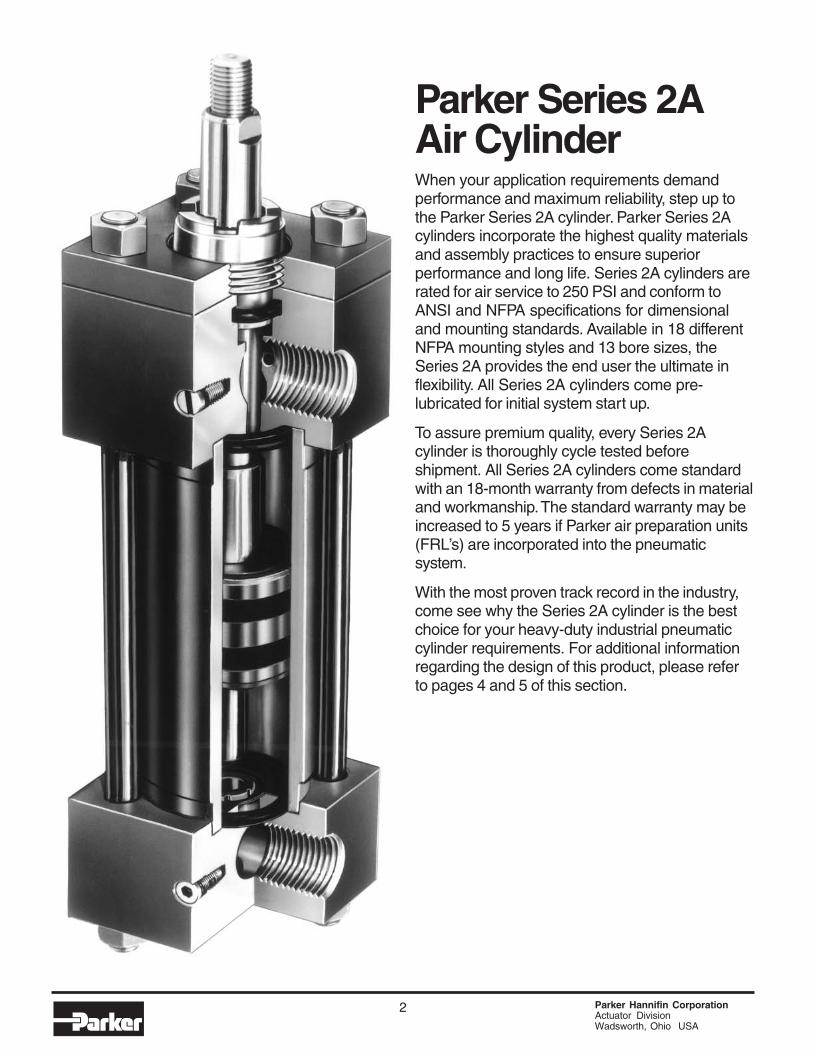
Parker Series 2AAir CylinderWhen your application requirements demandperformance and maximum reliability, step up tothe Parker Series 2A cylinder. Parker Series 2Acylinders incorporate the highest quality materialsand assembly practices to ensure superiorperformance and long life. Series 2A cylinders arerated for air service to 250 PSI and conform toANSI and NFPA specifications for dimensionaland mounting standards. Available in 18 differentNFPA mounting styles and 13 bore sizes, theSeries 2A provides the end user the ultimate inflexibility. All Series 2A cylinders come pre-lubricated for initial system start up.
To assure premium quality, every Series 2Acylinder is thoroughly cycle tested beforeshipment. All Series 2A cylinders come standardwith an 18-month warranty from defects in materialand workmanship. The standard warranty may beincreased to 5 years if Parker air preparation units(FRL’s) are incorporated into the pneumaticsystem.
With the most proven track record in the industry,come see why the Series 2A cylinder is the bestchoice for your heavy-duty industrial pneumaticcylinder requirements. For additional informationregarding the design of this product, please referto pages 4 and 5 of this section.

Heavy Duty Air CylindersSeries 2A
3 Parker Hannifin CorporationActuator DivisionWadsworth, Ohio USA
C052
Catalog AU03-0900P-2/NA
Specifications / Mountings
(NFPA MT2)
Style DB
Tie Rods Extended Both Ends Head Rectangular Flange
Head Square Flange Cap Rectangular Flange Cap Square Flange Side Lug
(NFPA MF2)
Style H
(NFPA MF6)
Style HB
(NFPA MS2)(NFPA MF5)
Style JB
(NFPA MX3) (NFPA MX2) (NFPA MX1)
Style TD
(NFPA MF1)
Style J
Centerline Lugs Side Tapped Side End Angles Side End Lugs
(NFPA MS4)
Style F
(NFPA MS1)
Style CB
(NFPA MS7)
Style G
(NFPA MS3)
Style E
Cap Fixed Clevis
(NFPA MP1)
Style BB
Available Mounting StylesTie Rods Extended Head End
Style TB
Tie Rods Extended Cap End
Standard Specifications• Heavy Duty Service – ANSI/(NFPA) T3.6.7R2-1996
Specifications and Mounting Dimension Standards• Standard Construction – Square Head – Tie Rod Design• Nominal Pressure – Up to 250 PSI Air Service• Standard Fluid – Filtered Air• Standard Temperature – -10°F. to +165°F.• Optional High Temperature +14°F. to +250°F.
Double Rod Cylinders
Cap Detachable Clevis
(NFPA MP2)
Style BC
Head Trunnion
(NFPA MT1)
Style D
Style KTB Shown
Intermediate Fixed Trunnion
(NFPA MT4)
Style DD
Spherical Bearing
Style SB
Note: Series 2A Air Cylinders fully meet ANSI/(NFPA) T3.6.7R2-1996 Specifications and Mounting Dimension Standards for Square Head Industrial Fluid Power Cylinders.Parker Style TB, JB, HB, C, DB, and BB are available in 7" bore size, see page 18.
• Bore Sizes – 1" through 14" (Larger sizes available)• Piston Rod Diameter – 1/2" through 51/2"• Mounting Styles – 18 standard styles at various application
ratings• Strokes – Available in any practical stroke length• Cushions – Optional at either end or both ends of stroke.
“Float Check” at cap end.• Rod Ends – Three Standard Choices – Specials to OrderIn line with our policy of continuing product improvement, specifications in this catalog are
subject to change.
Style C
Cap Trunnion
Most of the above illustratedmounting styles are available indouble rod cylinders.See Catalog Page 32.
1"-6", Page 67", Page 188"-14", Page 20
1"-6", Page 67", Page 188"-14", Page 20
Style TC
1"-6", Page 67", Page 188"-14", Page 20 1"-6", Page 6
1"-6", Page 87", Page 188"-14", Page 20 1"-6", Page 6
1"-6", Page 87", Page 188"-14", Page 20
1"-6", Page 107", Page 198"-14", Page 22
11/2"-6", Page 108"-14", Page 22
1"-6", Page 107", Page 198"-14", Page 24
1"-6", Page 128"-14", Page 26
1"-6", Page 128"-14", Page 24
1"-6", Page 167", Page 198"-14", Page 26 1"-6", Page 16
1"-6", Page 147", Page 198"-14", Page 28
1"-6", Page 147", Page 198"-14", Page 28
11/2"-6", Page 148"-14", Page 28
11/2"-6", Page 308"-14", Page 31
Parker Hannifin CorporationActuator DivisionWadsworth, Ohio USA
4
The inside story on whySeries 2A is your best choice inheavy duty pneumatic cylinders
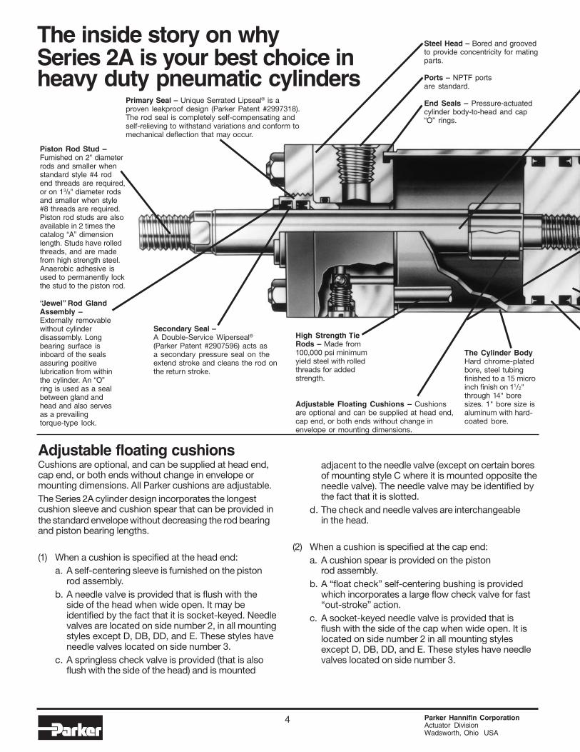
Primary Seal – Unique Serrated Lipseal® is aproven leakproof design (Parker Patent #2997318).The rod seal is completely self-compensating andself-relieving to withstand variations and conform tomechanical deflection that may occur.
Adjustable floating cushionsCushions are optional, and can be supplied at head end,cap end, or both ends without change in envelope ormounting dimensions. All Parker cushions are adjustable.The Series 2A cylinder design incorporates the longestcushion sleeve and cushion spear that can be provided inthe standard envelope without decreasing the rod bearingand piston bearing lengths.
(1) When a cushion is specified at the head end:a. A self-centering sleeve is furnished on the piston
rod assembly.b. A needle valve is provided that is flush with the
side of the head when wide open. It may beidentified by the fact that it is socket-keyed. Needlevalves are located on side number 2, in all mountingstyles except D, DB, DD, and E. These styles haveneedle valves located on side number 3.
c. A springless check valve is provided (that is alsoflush with the side of the head) and is mounted
adjacent to the needle valve (except on certain boresof mounting style C where it is mounted opposite theneedle valve). The needle valve may be identified bythe fact that it is slotted.
d. The check and needle valves are interchangeablein the head.
(2) When a cushion is specified at the cap end:a. A cushion spear is provided on the piston
rod assembly.b. A “float check” self-centering bushing is provided
which incorporates a large flow check valve for fast“out-stroke” action.
c. A socket-keyed needle valve is provided that isflush with the side of the cap when wide open. It islocated on side number 2 in all mounting stylesexcept D, DB, DD, and E. These styles have needlevalves located on side number 3.
Piston Rod Stud –Furnished on 2" diameterrods and smaller whenstandard style #4 rodend threads are required,or on 13/8" diameter rodsand smaller when style#8 threads are required.Piston rod studs are alsoavailable in 2 times thecatalog “A” dimensionlength. Studs have rolledthreads, and are madefrom high strength steel.Anaerobic adhesive isused to permanently lockthe stud to the piston rod.
Steel Head – Bored and groovedto provide concentricity for matingparts.
Ports – NPTF portsare standard.
End Seals – Pressure-actuatedcylinder body-to-head and cap“O” rings.
“Jewel” Rod GlandAssembly –Externally removablewithout cylinderdisassembly. Longbearing surface isinboard of the sealsassuring positivelubrication from withinthe cylinder. An “O”ring is used as a sealbetween gland andhead and also servesas a prevailingtorque-type lock.
High Strength TieRods – Made from100,000 psi minimumyield steel with rolledthreads for addedstrength.
The Cylinder BodyHard chrome-platedbore, steel tubingfinished to a 15 microinch finish on 11/2"through 14" boresizes. 1" bore size isaluminum with hard-coated bore.
Adjustable Floating Cushions – Cushionsare optional and can be supplied at head end,cap end, or both ends without change inenvelope or mounting dimensions.
Secondary Seal –A Double-Service Wiperseal®(Parker Patent #2907596) acts asa secondary pressure seal on theextend stroke and cleans the rod onthe return stroke.
5 Parker Hannifin CorporationActuator DivisionWadsworth, Ohio USA
CylinderBore
(Inches)
11/2
2
21/2
31/4
4
5
RodNumber
1
2
1
2
1
2
1
21
2
1
2
RodDiameter*(Inches)
5/81
5/8
13/85/8
13/4
1
21
21/21
31/2
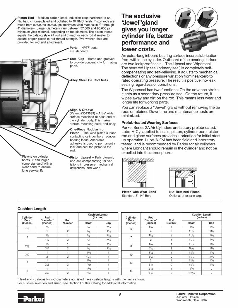
Piston Rod – Medium carbon steel, induction case-hardened to 54Rc, hard chrome-plated and polished to 10 RMS finish. Piston rods aremade from 90,000 to 100,000 psi minimum yield material in 1/2" through4" diameters. Larger diameters vary between 57,000 and 90,000 psiminimum yield material, depending on rod diameter. The piston threadequals the catalog style #4 rod end thread for each rod diameter toassure proper piston-to-rod thread strength. Two wrench flats areprovided for rod end attachment.
Cushion Length
CylinderBore
(Inches)
6
7
8
10
12
14
Cap13/16
13/16
13/16
13/16
13/16
13/16
1
11
1
1
1
Head*7/87/87/87/87/87/8
11/813/16
11/813/16
11/813/16
Cushion Length(Inches)
Cushion Length(Inches)
Cap11/411/411/411/411/4
11/4
13/413/413/4
13/42
2
Head*13/811/16
11/16
11/16
11/16
15/16
15/16
13/16
15/16
13/16
13/4
111/16
RodNumber
1
2
1
4
1
2
1
01
9
1
8
RodDiameter*(Inches)
13/84
13/8
2
13/8
51/2
13/451/22
51/221/2
51/2
*Head end cushions for rod diameters not listed have cushion lengths with the limits shown.For cushion selection and sizing, see Section I of this catalog for additional information.
Alloy Steel Tie Rod Nuts
Ports – NPTF portsare standard.
Steel Cap – Bored and groovedto provide concentricity for matingparts.
Align-A-Groove –(Patent #3043639) – A 3/16" widesurface machined at each end ofthe cylinder body. This makesprecise mounting quick and easy.
One-Piece Nodular IronPiston – The wide piston surfacecontacting cylinder bore reducesbearing loads. Anaerobicadhesive is used to permanentlylock and seal the piston to therod.
Piston Lipseal – Fully dynamicand self-compensating for var-iations in pressure, mechanicaldeflections, and wear.
The exclusive“Jewel” glandgives you longercylinder life, betterperformance andlower costs.An extra-long inboard bearing surface insures lubricationfrom within the cylinder. Outboard of the bearing surfaceare two leakproof seals – The Lipseal and Wiperseal.The serrated Lipseal (primary seal) is completely self-compensating and self-relieving. It adjusts to mechanicaldeflections or any pressure variation from near-zero torated operating pressure. The result is positive, no-leaksealing regardless of conditions.The Wiperseal has two functions: On the advance stroke,it acts as a secondary pressure seal. On the return, itwipes away any dirt on the rod. This means less wear andlonger life for working parts.You can replace a “Jewel” gland without removing the tierods or retainer. Downtime and maintenance costs areminimized.
Prelubricated Wearing SurfacesParker Series 2A Air Cylinders are factory prelubricated.Lube-A-Cyl applied to seals, piston, cylinder bore, pistonrod and gland surfaces provides lubrication for initial startup operation. Lube-A-Cyl has been field and laboratorytested, and is recommended by Parker for air cylinderswhere lubricant should remain in the cylinder and not beexpelled into the atmosphere.
Pistons on cylinderbores 8" and largercome standard with awear band to ensurelong service life.
Piston with Wear BandStandard 8"-14" Bore
Nut Retained PistonOptional at extra charge
MM B
NA
VWA
LA
C
18
CC
D WRENCHFLATS
MM B
NA
VWA
LA
C
18
KK
D WRENCHFLATS
MM B
NA
V
A
WC
18
KK
D WRENCHFLATS
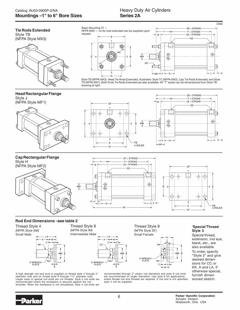
Rod End Dimensions — see table 2Thread Style 9(NFPA Style SF)Small Female
Thread Style 8(NFPA Style IM)Intermediate Male
Thread Style 4(NFPA Style SM)Small Male
A high strength rod end stud is supplied on thread style 4 through 2"diameter rods and on thread style 8 through 13/8" diameter rods.Larger sizes or special rod ends are cut threads. Style 4 rod ends arerecommended where the workpiece is secured against the rodshoulder. When the workpiece is not shouldered, style 4 rod ends are
recommended through 2" piston rod diameters and style 8 rod endsare recommended on larger diameters. Use style 9 for applicationswhere female rod end threads are required. If rod end is not specified,style 4 will be supplied.
“Special” ThreadStyle 3Special thread,extension, rod eye,blank, etc., arealso available.To order, specify“Style 3” and givedesired dimen-sions for CC orKK, A and LA. Ifotherwise special,furnish dimen-sioned sketch.
Heavy Duty Air CylindersSeries 2A
Parker Hannifin CorporationActuator DivisionWadsworth, Ohio USA
6
C052
2 4R E
E FB4 HOLES
TF
3
UF
1
G
XF
FK
J
P + STROKELB + STROKE
ZF + STROKE
W
EE
Y
F
MM
24E R
E
TF
3
UF
1
FB4 HOLES
G
WF
F J
P + STROKELB + STROKE
ZB + STROKE
W
EE
Y
K
MM
24E R
R
3
E
AA
1
GBB F J
P + STROKELB + STROKE
ZB + STROKE
W
EE
Y
K
MM
DD
Tie Rods ExtendedStyle TB(NFPA Style MX3)
Head Rectangular FlangeStyle J(NFPA Style MF1)
Cap Rectangular FlangeStyle H(NFPA Style MF2)
Style TB (NFPA MX3). Head Tie Rods Extended, illustrated: Style TC (NFPA MX2), Cap Tie Rods Extended; and StyleTD (NFPA MX1), Both Ends Tie Rods Extended are also available. All “T” styles can be dimensioned from Style TBdrawing at right.
Basic Mounting (T) —NFPA MX0 — no tie rods extended can be supplied uponrequest.
Catalog AU03-0900P-2/NA
Mountings – 1" to 6" Bore Sizes
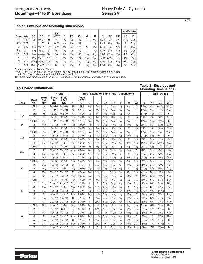
Table 1—Envelope and Mounting Dimensions
Table 2—Rod Dimensions
Note: Shaded areas indicate non-standard rod sizes that are available and made to order.
* Cushions not available on 1" bore.** On 1", 11/2", 2" and 21/2" bore sizes, the head-end (only) pipe thread is not full depth on cylinders with No. 2 rods. Minimum of three full threads available.
Heavy Duty Air CylindersSeries 2A
7 Parker Hannifin CorporationActuator DivisionWadsworth, Ohio USA
C052
1(Std.)2
1(Std.)2
1(Std.)23
1(Std.)234
1(Std.)234
1(Std.)2345
1(Std.)234567
1(Std.)234567
37/8
44
41/8
47/847/851/853/4
47/847/8
553/85
55/8
53/851/8
651/253/4
61/4
67/861/2
63/4
61/471/8
61/2
63/467/8
61/2
73/863/4
771/873/8
73/8
73/88
75/8
73/4888
Rod Style Style +.000Rod Dia. 8 4 & 9 -.002
Bore No. MM CC KK A B C D LA NA V W WF Y XF ZB ZF.999
1.1241.1241.4991.1241.9991.4991.1242.3741.4991.9991.4992.6241.9992.3741.4993.1241.9992.3742.6241.4994.2491.9992.3742.6243.1243.7491.9994.7492.3742.6243.1243.7494.249
5/83/43/4
11/83/4
15/8
11/83/42
11/8
15/811/8
21/4
15/82
11/8
315/8
221/411/8
31/2
15/82
21/4
331/2
15/8
42
21/4
331/2
31/2
3/83/83/81/23/85/81/23/83/41/25/81/27/85/83/41/2
15/83/47/81/2
15/83/47/8
11
5/8
13/47/8
111
3/81/2
1/2
7/81/2
11/87/81/2
11/27/8
11/87/8
111/16
11/8
11/27/8
21/16
11/811/2
111/16
7/83
11/8
11/2111/16
21/16
25/811/8
33/8
11/2111/16
21/16
25/83
5/16-247/16-207/16-203/4-16
7/16-201-143/4-16
7/16-2011/4-123/4-161-143/4-16
11/2-121-14
11/4-123/4-16
17/8-121-14
11/4-1211/2-123/4-16
21/2-121-14
11/4-1211/2-1217/8-1221/4-121-143-12
11/4-1211/2-1217/8-1221/4-1221/2-12
11/4
13/813/8
21/8
13/827/8
21/8
13/8
31/2
21/8
27/8
17/8
35/8
25/8
31/4
17/8
45/8
25/8
31/4
35/8
17/8
51/8
25/8
31/4
35/8
45/8
51/8
21/2
51/2
31/8
31/2
41/2
55
7/16
9/16
9/16
15/16
9/16
15/16
15/16
9/16
111/16
15/16
15/16
15/16
115/16
15/16
111/16
15/16
23/8
15/16
111/16
115/16
15/16
33/8
15/16
111/16
115/16
23/8
27/8
15/16
37/8
111/16
115/16
23/8
27/8
33/8
1/41/41/41/21/45/81/2
1/43/41/2
5/81/41/23/81/21/45/83/81/21/21/45/83/81/21/25/85/81/41/23/83/81/21/21/2
5/85/85/8
15/8
11/4
15/8
11/2
111/43/4
13/8
111/43/4
15/8
111/4
13/83/4
15/8
111/4
13/8
15/8
15/87/8
11/2
11/8
11/4
11/2
11/2
11/2
111
13/8
115/813/8
117/813/8
15/8
13/82
15/8
17/813/8
21/4
15/817/8
213/821/4
15/8
17/82
21/4
21/415/8
21/4
17/82
21/4
21/421/4
115/16
115/16
115/16
25/16
115/16
29/16
25/16
115/16
213/16
25/16
29/16
27/16
31/16
211/16
215/16
27/16
35/16
211/16
215/16
31/16
27/16
35/16
211/16
215/16
31/16
35/16
35/16
213/16
37/16
31/16
33/16
37/16
37/16
37/16
7/16-201/2-201/2-207/8-141/2-2011/4-127/8-141/2-2011/2-127/8-1411/4-127/8-1413/4-1211/4-1211/2-127/8-1421/4-1211/4-1211/2-1213/4-127/8-1431/4-1211/4-1211/2-1213/4-1221/4-1223/4-1211/4-1233/4-1211/2-1213/4-1221/4-1223/4-1231/4-12
Thread
1
11/2
2
21/2
31/4
4
5
6
1/25/85/815/8
13/815/8
13/4
113/8
12
13/8
13/4
121/2
13/8
13/4
21
31/2
13/8
13/4
221/2
313/8
413/4
221/2
331/2
Rod Extensions and Pilot Dimensions
41/2
41/2
45/8
545/8
51/4
543/4
55/8
51/8
53/8
55/8
61/4
57/8
61/8
55/8
61/2
57/8
61/8
61/4
57/8
63/4
61/8
63/8
61/2
63/4
63/4
65/8
71/4
67/8
771/4
71/4
71/4
411/16
411/16
47/8
51/4
415/16
59/16
55/16
51/16
515/16
57/16
511/16
665/8
61/4
61/2
667/8
61/4
61/2
65/8
65/16
73/16
69/16
613/16
615/16
73/16
73/16
71/16
711/16
75/16
77/16
711/16
711/16
711/16
Add Stroke
EEBore AA BB DD E NPTF F FB G J K R TF UF LB P
1*11/22
21/2
31/4
456
■
221/2
333/4
41/2
51/2
61/2
1/43/8**3/8**3/8**
1/21/21/23/4
3/83/83/83/85/85/85/83/4
1.532.022.63.13.94.75.86.9
3/4
111/811/813/813/8
113/16
113/16
10-241/4-285/16-245/16-243/8-243/8-241/2-201/2-20
1.081.431.842.192.763.324.104.88
1111
11/411/4
11/4
11/2
3/16
1/45/16
5/16
3/83/87/16
7/16
11/211/211/211/213/4
13/4
13/4
2
223/4
33/8
37/8411/16
57/16
65/8
75/8
21/2
33/8
41/8
45/851/261/4
75/8
85/8
Add Stroke
21/8
21/4
21/4
23/825/825/827/831/8
1/45/16
3/83/87/16
7/16
9/16
9/16
■ 1" bore head dimension is 13/4" x 11/2". See page 16 for dimensional information on 1" bore cylinders.
Catalog AU03-0900P-2/NA
Mountings – 1" to 6" Bore Sizes
Table 3 — Envelope andMounting Dimensions

MM B
NA
VWA
LA
C
18
CC
D WRENCHFLATS
MM B
NA
VWA
LA
C
18
KK
D WRENCHFLATS
MM B
NA
V
A
WC
18
KK
D WRENCHFLATS
Rod End Dimensions — see table 2Thread Style 9(NFPA Style SF)Small Female
Thread Style 8(NFPA Style IM)Intermediate Male
Thread Style 4(NFPA Style SM)Small Male
A high strength rod end stud is supplied on thread style 4 through 2"diameter rods and on thread style 8 through 13/8" diameter rods.Larger sizes or special rod ends are cut threads. Style 4 rod ends arerecommended where the workpiece is secured against the rodshoulder. When the workpiece is not shouldered, style 4 rod ends are
recommended through 2" piston rod diameters and style 8 rod endsare recommended on larger diameters. Use style 9 for applicationswhere female rod end threads are required. If rod end is not specified,style 4 will be supplied.
“Special” ThreadStyle 3Special thread,extension, rod eye,blank, etc., arealso available.To order, specify“Style 3” and givedesired dimen-sions for CC orKK, A and LA. Ifotherwise special,furnish dimen-sioned sketch.
Heavy Duty Air CylindersSeries 2A
Parker Hannifin CorporationActuator DivisionWadsworth, Ohio USA
8
C052
Head Square FlangeStyle JB(NFPA Style MF5)
Cap Square FlangeStyle HB(NFPA Style MF6)
2 4R TF E
R
TF
3
UF
UFE1
FB8 HOLES
G
XF
F
K
J
P + STROKELB + STROKE
ZF + STROKE
W
EE
Y
F
MM
24E UF R
R
TF
3
TF
UFE1
FB8 HOLES
G
WF
F J
P + STROKELB + STROKE
ZB + STROKE
W
EE
Y
K
MM
Catalog AU03-0900P-2/NA
Mountings – 1" to 6" Bore Sizes
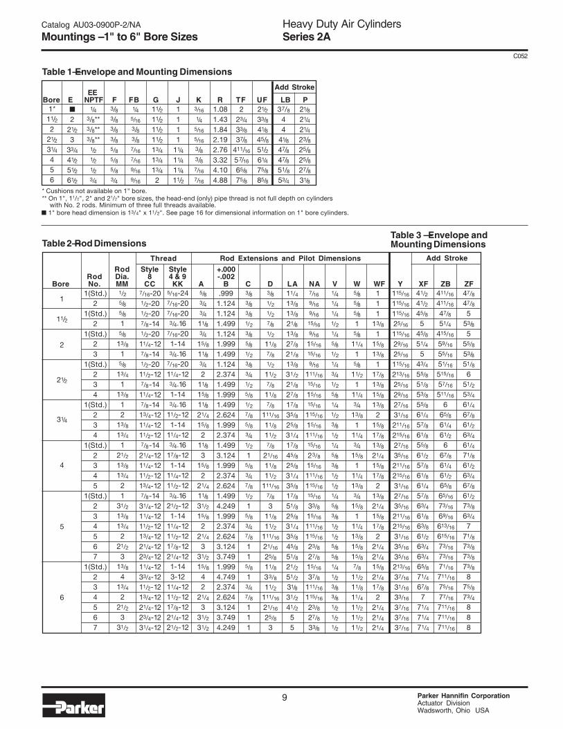
Table 1—Envelope and Mounting Dimensions
Table 2—Rod Dimensions
Note: Shaded areas indicate non-standard rod sizes that are available and made to order.
* Cushions not available on 1" bore.** On 1", 11/2", 2" and 21/2" bore sizes, the head-end (only) pipe thread is not full depth on cylinders with No. 2 rods. Minimum of three full threads available.
Heavy Duty Air CylindersSeries 2A
9 Parker Hannifin CorporationActuator DivisionWadsworth, Ohio USA
C052
1(Std.)2
1(Std.)2
1(Std.)23
1(Std.)234
1(Std.)234
1(Std.)2345
1(Std.)234567
1(Std.)234567
Rod Style Style +.000Rod Dia. 8 4 & 9 -.002
Bore No. MM CC KK A B C D LA NA V W WF Y XF ZB ZF.999
1.1241.1241.4991.1241.9991.4991.1242.3741.4991.9991.4992.6241.9992.3741.4993.1241.9992.3742.6241.4994.2491.9992.3742.6243.1243.7491.9994.7492.3742.6243.1243.7494.249
5/83/43/4
11/83/4
15/8
11/83/42
11/8
15/811/8
21/4
15/82
11/8
315/8
221/411/8
31/2
15/82
21/4
331/2
15/8
42
21/4
331/2
31/2
3/83/83/81/2
3/85/81/2
3/83/41/2
5/81/2
7/85/83/41/2
15/83/47/81/2
15/83/47/8
11
5/8
13/47/8
111
3/81/21/27/81/2
11/87/81/2
11/27/8
11/87/8
111/16
11/8
11/27/8
21/16
11/811/2
111/16
7/83
11/8
11/2111/16
21/16
25/811/8
33/8
11/2111/16
21/16
25/83
5/16-247/16-207/16-203/4-16
7/16-201-143/4-16
7/16-2011/4-123/4-161-143/4-16
11/2-121-14
11/4-123/4-16
17/8-121-14
11/4-1211/2-123/4-16
21/2-121-14
11/4-1211/2-1217/8-1221/4-121-143-12
11/4-1211/2-1217/8-1221/4-1221/2-12
11/4
13/813/8
21/8
13/827/8
21/8
13/8
31/2
21/8
27/8
17/8
35/8
25/8
31/4
17/8
45/8
25/8
31/4
35/8
17/8
51/8
25/8
31/4
35/8
45/8
51/8
21/2
51/2
31/8
31/2
41/2
55
7/16
9/16
9/16
15/16
9/16
15/16
15/16
9/16
111/16
15/16
15/16
15/16
115/16
15/16
111/16
15/16
23/8
15/16
111/16
115/16
15/16
33/8
15/16
111/16
115/16
23/8
27/8
15/16
37/8
111/16
115/16
23/8
27/8
33/8
1/41/41/41/21/45/81/21/43/41/25/81/41/23/81/21/45/83/81/21/21/45/83/81/21/25/85/81/41/23/83/81/21/21/2
5/85/85/8
15/8
11/4
15/8
11/2
111/43/4
13/8
111/43/4
15/8
111/4
13/83/4
15/8
111/4
13/8
15/8
15/87/8
11/2
11/8
11/4
11/2
11/2
11/2
111
13/8
115/813/8
117/813/8
15/8
13/82
15/8
17/813/8
21/4
15/817/8
213/821/4
15/8
17/82
21/4
21/415/8
21/4
17/82
21/4
21/421/4
115/16
115/16
115/16
25/16
115/16
29/16
25/16
115/16
213/16
25/16
29/16
27/16
31/16
211/16
215/16
27/16
35/16
211/16
215/16
31/16
27/16
35/16
211/16
215/16
31/16
35/16
35/16
213/16
37/16
31/16
33/16
37/16
37/16
37/16
7/16-201/2-201/2-207/8-141/2-2011/4-127/8-141/2-2011/2-127/8-1411/4-127/8-1413/4-1211/4-1211/2-127/8-1421/4-1211/4-1211/2-1213/4-127/8-1431/4-1211/4-1211/2-1213/4-1221/4-1223/4-1211/4-1233/4-1211/2-1213/4-1221/4-1223/4-1231/4-12
Thread
1
11/2
2
21/2
31/4
4
5
6
1/25/85/81
5/8
13/81
5/8
13/4
113/8
12
13/8
13/4
121/2
13/8
13/4
21
31/2
13/8
13/4
221/2
313/8
413/4
221/2
331/2
Rod Extensions and Pilot Dimensions
41/2
41/2
45/8
545/8
51/4
543/4
55/8
51/8
53/8
55/8
61/4
57/8
61/8
55/8
61/2
57/8
61/8
61/4
57/8
63/4
61/8
63/8
61/2
63/4
63/4
65/8
71/4
67/8
771/4
71/4
71/4
411/16
411/16
47/8
51/4
415/16
59/16
55/16
51/16
515/16
57/16
511/16
665/8
61/4
61/2
667/8
61/4
61/2
65/8
65/16
73/16
69/16
613/16
615/16
73/16
73/16
71/16
711/16
75/16
77/16
711/16
711/16
711/16
47/847/8
553/85
55/8
53/851/8
651/253/4
61/4
67/861/2
63/4
61/471/8
61/2
63/467/8
61/2
73/863/4
771/873/8
73/8
73/88
75/8
73/4888
Add Stroke
1*11/22
21/2
31/4
456
■
221/2
333/4
41/2
51/2
61/2
1/43/8**3/8**3/8**
1/21/21/23/4
3/83/83/83/85/85/85/83/4
11/211/211/211/213/4
13/4
13/4
2
1111
11/4
11/4
11/4
11/2
3/16
1/45/16
5/16
3/83/87/16
7/16
1.081.431.842.192.763.324.104.88
37/8
44
41/8
47/847/851/853/4
21/8
21/4
21/4
23/825/825/827/831/8
1/45/16
3/83/87/16
7/16
9/16
9/16
223/4
33/8
37/8411/16
57/16
65/8
75/8
21/2
33/8
41/8
45/851/261/4
75/8
85/8
EEBore E NPTF F FB G J K R TF UF LB P
■ 1" bore head dimension is 13/4" x 11/2". See page 16 for dimensional information on 1" bore cylinders.
Catalog AU03-0900P-2/NA
Mountings – 1" to 6" Bore Sizes
Add Stroke
Table 3 — Envelope andMounting Dimensions
MM B
NA
VWA
LA
C
18
CC
D WRENCHFLATS
MM B
NA
VWA
LA
C
18
KK
D WRENCHFLATS
MM B
NA
V
A
WC
18
KK
D WRENCHFLATS
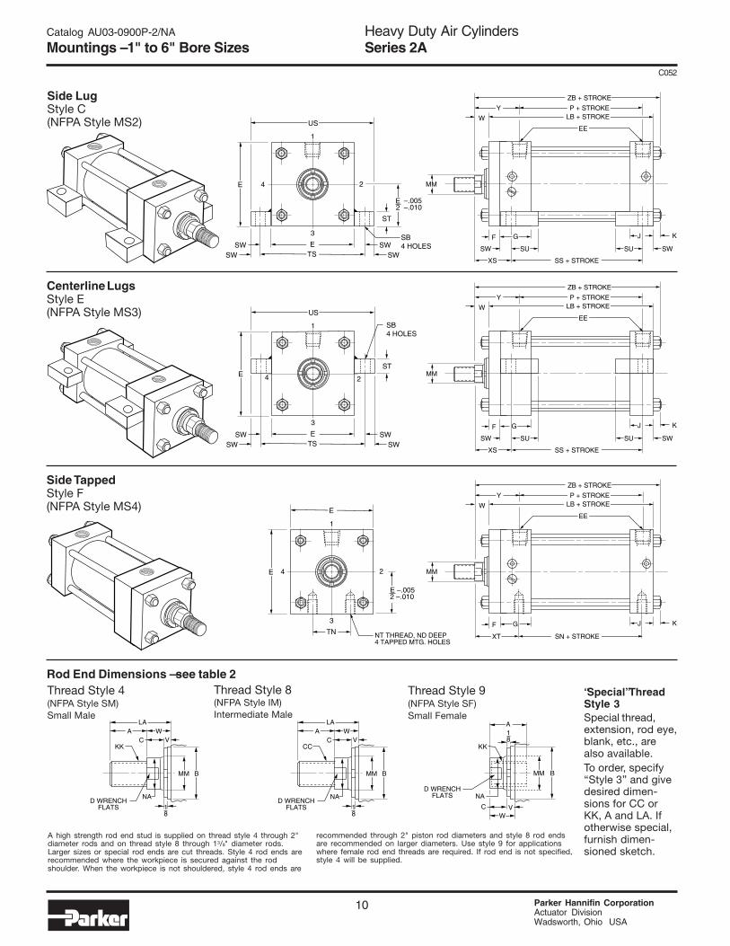
Rod End Dimensions — see table 2Thread Style 9(NFPA Style SF)Small Female
Thread Style 8(NFPA Style IM)Intermediate Male
Thread Style 4(NFPA Style SM)Small Male
A high strength rod end stud is supplied on thread style 4 through 2"diameter rods and on thread style 8 through 13/8" diameter rods.Larger sizes or special rod ends are cut threads. Style 4 rod ends arerecommended where the workpiece is secured against the rodshoulder. When the workpiece is not shouldered, style 4 rod ends are
recommended through 2" piston rod diameters and style 8 rod endsare recommended on larger diameters. Use style 9 for applicationswhere female rod end threads are required. If rod end is not specified,style 4 will be supplied.
“Special” ThreadStyle 3Special thread,extension, rod eye,blank, etc., arealso available.To order, specify“Style 3” and givedesired dimen-sions for CC orKK, A and LA. Ifotherwise special,furnish dimen-sioned sketch.
Heavy Duty Air CylindersSeries 2A
Parker Hannifin CorporationActuator DivisionWadsworth, Ohio USA
10
C052
24E
E –.0052 –.010
TN
3
E
1
G
XT SN + STROKE
F J
P + STROKELB + STROKE
ZB + STROKE
W
EE
Y
K
MM
NT THREAD, ND DEEP4 TAPPED MTG. HOLES
24E
ST
SWSB4 HOLES
SW
–.005–.010
SWSW
ETS
3
US
1
G
XS SS + STROKE
SU SU
F
SW SW
J
P + STROKELB + STROKE
ZB + STROKE
W
EE
Y
K
MM
E2
24E ST
SW
SB4 HOLES
SWSW
SW
ETS
3
US
1
G
XS SS + STROKE
SU SU
F
SW SW
J
P + STROKELB + STROKE
ZB + STROKE
W
EE
Y
K
MM
Side LugStyle C(NFPA Style MS2)
Centerline LugsStyle E(NFPA Style MS3)
Side TappedStyle F(NFPA Style MS4)
Catalog AU03-0900P-2/NA
Mountings – 1" to 6" Bore Sizes
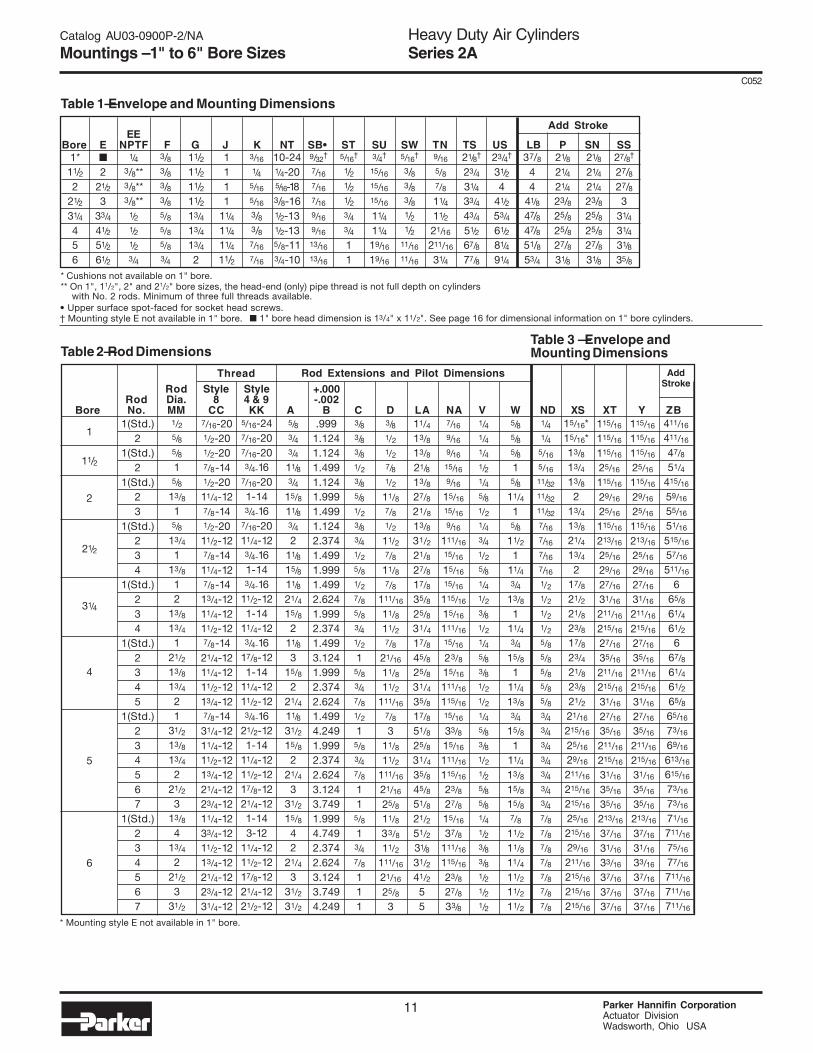
Table 1—Envelope and Mounting Dimensions
Table 2—Rod Dimensions
Note: Shaded areas indicate non-standard rod sizes that are available and made to order.
Table 3 — Envelope andMounting Dimensions
* Cushions not available on 1" bore.** On 1", 11/2", 2" and 21/2" bore sizes, the head-end (only) pipe thread is not full depth on cylinders with No. 2 rods. Minimum of three full threads available.
Heavy Duty Air CylindersSeries 2A
11 Parker Hannifin CorporationActuator DivisionWadsworth, Ohio USA
C052
1(Std.)2
1(Std.)2
1(Std.)23
1(Std.)234
1(Std.)234
1(Std.)2345
1(Std.)234567
1(Std.)234567
• Upper surface spot-faced for socket head screws.† Mounting style E not available in 1" bore.
EEBore E NPTF F G J K NT SB• ST SU SW TN TS US LB P SN SS
1*11/22
21/2
31/4
456
Rod Style Style +.000Rod Dia. 8 4 & 9 -.002
Bore No. MM CC KK A B C D LA NA V W ND XS XT Y ZB.999
1.1241.1241.4991.1241.9991.4991.1242.3741.4991.9991.4992.6241.9992.3741.4993.1241.9992.3742.6241.4994.2491.9992.3742.6243.1243.7491.9994.7492.3742.6243.1243.7494.249
5/83/43/4
11/83/4
15/8
11/83/42
11/8
15/811/8
21/4
15/82
11/8
315/8
221/411/8
31/2
15/82
21/4
331/2
15/8
42
21/4
331/2
31/2
3/83/83/81/2
3/85/81/2
3/83/41/2
5/81/2
7/85/83/41/2
15/83/47/81/2
15/83/47/8
11
5/8
13/47/8
111
3/81/21/27/81/2
11/87/81/2
11/27/8
11/87/8
111/16
11/8
11/27/8
21/16
11/811/2
111/16
7/83
11/8
11/2111/16
21/16
25/811/8
33/8
11/2111/16
21/16
25/83
5/16-247/16-207/16-203/4-16
7/16-201-143/4-16
7/16-2011/4-123/4-161-143/4-16
11/2-121-14
11/4-123/4-16
17/8-121-14
11/4-1211/2-123/4-16
21/2-121-14
11/4-1211/2-1217/8-1221/4-121-143-12
11/4-1211/2-1217/8-1221/4-1221/2-12
11/4
13/813/8
21/8
13/827/8
21/8
13/8
31/2
21/8
27/8
17/8
35/8
25/8
31/4
17/8
45/8
25/8
31/4
35/8
17/8
51/8
25/8
31/4
35/8
45/8
51/8
21/2
51/2
31/8
31/2
41/2
55
7/16
9/16
9/16
15/16
9/16
15/16
15/16
9/16
111/16
15/16
15/16
15/16
115/16
15/16
111/16
15/16
23/8
15/16
111/16
115/16
15/16
33/8
15/16
111/16
115/16
23/8
27/8
15/16
37/8
111/16
115/16
23/8
27/8
33/8
1/41/41/41/21/45/81/21/43/41/25/81/41/23/81/21/45/83/81/21/21/45/83/81/21/25/85/81/41/23/83/81/21/21/2
5/85/85/8
15/8
11/4
15/8
11/2
111/43/4
13/8
111/43/4
15/8
111/4
13/83/4
15/8
111/4
13/8
15/8
15/87/8
11/2
11/8
11/4
11/2
11/2
11/2
1/41/4
5/16
5/16
11/32
11/32
11/32
7/16
7/16
7/16
7/16
1/2
1/2
1/2
1/2
5/85/85/85/85/83/43/43/43/43/43/43/47/87/87/87/87/87/87/8
7/16-201/2-201/2-207/8-141/2-2011/4-127/8-141/2-2011/2-127/8-1411/4-127/8-1413/4-1211/4-1211/2-127/8-1421/4-1211/4-1211/2-1213/4-127/8-1431/4-1211/4-1211/2-1213/4-1221/4-1223/4-1211/4-1233/4-1211/2-1213/4-1221/4-1223/4-1231/4-12
Thread
1
11/2
2
21/2
31/4
4
5
6
1/25/85/81
5/8
13/81
5/8
13/4
113/8
12
13/8
13/4
121/2
13/8
13/4
21
31/2
13/8
13/4
221/2
313/8
413/4
221/2
331/2
Rod Extensions and Pilot Dimensions AddStroke
411/16
411/16
47/8
51/4
415/16
59/16
55/16
51/16
515/16
57/16
511/16
665/8
61/4
61/2
667/8
61/4
61/2
65/8
65/16
73/16
69/16
613/16
615/16
73/16
73/16
71/16
711/16
75/16
77/16
711/16
711/16
711/16
15/16*15/16*13/8
13/4
13/82
13/4
13/821/4
13/4
217/8
21/2
21/823/8
17/8
23/421/8
23/8
21/221/16
215/16
25/16
29/16
211/16
215/16
215/16
25/16
215/16
29/16
211/16
215/16
215/16
215/16
115/16
115/16
115/16
25/16
115/16
29/16
25/16
115/16
213/16
25/16
29/16
27/16
31/16
211/16
215/16
27/16
35/16
211/16
215/16
31/16
27/16
35/16
211/16
215/16
31/16
35/16
35/16
213/16
37/16
31/16
33/16
37/16
37/16
37/16
115/16
115/16
115/16
25/16
115/16
29/16
25/16
115/16
213/16
25/16
29/16
27/16
31/16
211/16
215/16
27/16
35/16
211/16
215/16
31/16
27/16
35/16
211/16
215/16
31/16
35/16
35/16
213/16
37/16
31/16
33/16
37/16
37/16
37/16
■
221/2
333/4
41/2
51/2
61/2
1/43/8**3/8**3/8**
1/21/21/23/4
3/83/83/83/85/85/85/83/4
11/211/211/211/213/4
13/4
13/4
2
1111
11/4
11/4
11/4
11/2
3/16
1/45/16
5/16
3/83/87/16
7/16
37/8
44
41/8
47/847/851/853/4
21/8
21/4
21/4
23/825/825/827/831/8
Add Stroke
10-241/4-205/16-183/8-161/2-131/2-135/8-113/4-10
9/32†
7/16
7/16
7/16
9/16
9/16
13/16
13/16
5/16†
1/21/21/23/43/4
11
3/4†
15/16
15/16
15/16
11/4
11/4
19/16
19/16
5/16†
3/83/83/81/21/2
11/16
11/16
9/16
5/87/8
11/4
11/2
21/16
211/16
31/4
21/8†
23/4
31/4
33/4
43/4
51/2
67/8
77/8
23/4†
31/2
441/2
53/4
61/2
81/4
91/4
21/8
21/4
21/4
23/825/825/827/831/8
27/8†
27/827/83
31/4
31/4
31/8
35/8
* Mounting style E not available in 1" bore.
■ 1" bore head dimension is 13/4" x 11/2". See page 16 for dimensional information on 1" bore cylinders.
Catalog AU03-0900P-2/NA
Mountings – 1" to 6" Bore Sizes

MM B
NA
VWA
LA
C
18
CC
D WRENCHFLATS
MM B
NA
VWA
LA
C
18
KK
D WRENCHFLATS
MM B
NA
V
A
WC
18
KK
D WRENCHFLATS
Rod End Dimensions — see table 2Thread Style 9(NFPA Style SF)Small Female
Thread Style 8(NFPA Style IM)Intermediate Male
Thread Style 4(NFPA Style SM)Small Male
A high strength rod end stud is supplied on thread style 4 through 2"diameter rods and on thread style 8 through 13/8" diameter rods.Larger sizes or special rod ends are cut threads. Style 4 rod ends arerecommended where the workpiece is secured against the rodshoulder. When the workpiece is not shouldered, style 4 rod ends are
recommended through 2" piston rod diameters and style 8 rod endsare recommended on larger diameters. Use style 9 for applicationswhere female rod end threads are required. If rod end is not specified,style 4 will be supplied.
“Special” ThreadStyle 3Special thread,extension, rod eye,blank, etc., arealso available.To order, specify“Style 3” and givedesired dimen-sions for CC orKK, A and LA. Ifotherwise special,furnish dimen-sioned sketch.
Heavy Duty Air CylindersSeries 2A
Parker Hannifin CorporationActuator DivisionWadsworth, Ohio USA
12
C052
Side End AnglesStyle CB(NFPA Style MS1)
Side End LugsStyle G(NFPA Style MS7)
2
4
E
AH
AT
3
E
1
G
AT
SA + STROKEF
J
P + STROKELB + STROKE
XA + STROKEZA + STROKE
W
Y
ALK
AO
MM S
AB6 HOLES
ALAO
EE
4E
EB4 HOLES
RES ES
3
E
1
G
SE + STROKE
EO EL EL
F J
P + STROKELB + STROKE
XE + STROKE
ZE + STROKE
W
K EE
Y
EO
MM2
ET
—.005—.010
E2
164
Catalog AU03-0900P-2/NA
Mountings – 1" to 6" Bore Sizes
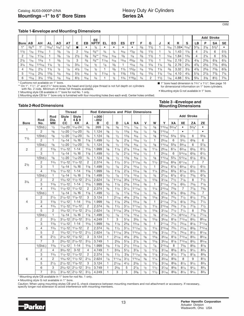
Table 1—Envelope and Mounting Dimensions
Table 2—Rod Dimensions
Note: Shaded areas indicate non-standard rod sizes that are available and made to order.
Table 3 — Envelope andMounting Dimensions
* Cushions not available on 1" bore.** On 1", 11/2", 2" and 21/2" bore sizes, the head-end (only) pipe thread is not full depth on cylinders with No. 2 rods. Minimum of three full threads available.
Heavy Duty Air CylindersSeries 2A
13 Parker Hannifin CorporationActuator DivisionWadsworth, Ohio USA
C052
1(Std.)2
1(Std.)2
1(Std.)23
1(Std.)234
1(Std.)234
1(Std.)2345
1(Std.)234567
1(Std.)234567
Add Stroke EE
Bore AB AH AL AO AT E EB NPTF EL EO ES ET F G J K R S LB P SA SE1*
11/22
21/2
31/4
456
3/8†‡
7/16
7/16
7/16
9/16
9/16
11/16
13/16
1†
13/16
17/16
15/8
115/16
21/4
23/4
31/4
13/16†
111
11/4
11/4
13/813/8
5/16†
3/83/83/81/21/25/85/8
1/8†
1/81/81/81/81/83/16
3/16
■
221/2
333/4
41/2
51/2
61/2
•5/16
3/83/87/16
7/16
9/16
9/16
1/43/8**3/8**3/8**
1/21/21/23/4
•3/4
15/16
11/16
7/8
111/16
1
•1/4
5/16
5/16
3/83/81/21/2
•9/16
5/813/16
111/413/813/4
•17/32
5/825/32
15/16
15/32
13/8119/32
3/83/83/83/85/85/85/83/4
11/211/211/211/213/4
13/4
13/4
2
1111
11/4
11/4
11/4
11/2
3/16
1/45/16
5/16
3/83/87/16
7/16
1.08•1.431.842.192.763.324.104.88
15/16†
11/4
13/4
21/4
23/4
31/2
41/4
51/4
37/844
41/8
47/847/851/853/4
21/8
21/4
21/4
23/825/825/827/831/8
51/2†
66
61/8
73/873/877/881/2
•51/257/861/4
65/867/871/4
73/4
Rod Style Style +.000Rod Dia. 8 4 & 9 -.002
Bore No. MM CC KK A B C D LA NA V W Y XA XE ZA ZE.999
1.1241.1241.4991.1241.9991.4991.1242.3741.4991.9991.4992.6241.9992.3741.4993.1241.9992.3742.6241.4994.2491.9992.3742.6243.1243.7491.9994.7492.3742.6243.1243.7494.249
5/83/43/4
11/83/4
15/8
11/83/42
11/8
15/811/8
21/4
15/82
11/8
315/8
221/411/8
31/2
15/82
21/4
331/2
15/8
42
21/4
331/2
31/2
3/83/83/81/2
3/85/81/2
3/83/41/2
5/81/2
7/85/83/41/2
15/83/47/81/2
15/83/47/8
11
5/8
13/47/8
111
3/81/21/27/81/2
11/87/81/2
11/27/8
11/87/8
111/16
11/8
11/27/8
21/16
11/811/2
111/16
7/83
11/8
11/2111/16
21/16
25/811/8
33/8
11/2111/16
21/16
25/83
5/16-247/16-207/16-203/4-16
7/16-201-143/4-16
7/16-2011/4-123/4-161-143/4-16
11/2-121-14
11/4-123/4-16
17/8-121-14
11/4-1211/2-123/4-16
21/2-121-14
11/4-1211/2-1217/8-1221/4-121-143-12
11/4-1211/2-1217/8-1221/4-1221/2-12
11/4
13/813/8
21/8
13/827/8
21/8
13/8
31/2
21/8
27/8
17/8
35/8
25/8
31/4
17/8
45/8
25/8
31/4
35/8
17/8
51/8
25/8
31/4
35/8
45/8
51/8
21/2
51/2
31/8
31/2
41/2
55
7/16
9/16
9/16
15/16
9/16
15/16
15/16
9/16
111/16
15/16
15/16
15/16
115/16
15/16
111/16
15/16
23/8
15/16
111/16
115/16
15/16
33/8
15/16
111/16
115/16
23/8
27/8
15/16
37/8
111/16
115/16
23/8
27/8
33/8
1/41/41/41/21/45/81/21/43/41/25/81/41/23/81/21/45/83/81/21/21/45/83/81/21/25/85/81/41/23/83/81/21/21/2
5/85/85/8
15/8
11/4
15/8
11/2
111/43/4
13/8
111/43/4
15/8
111/4
13/83/4
15/8
111/4
13/8
15/8
15/87/8
11/2
11/8
11/4
11/2
11/2
11/2
7/16-201/2-201/2-207/8-141/2-2011/4-127/8-141/2-2011/2-127/8-1411/4-127/8-1413/4-1211/4-1211/2-127/8-1421/4-1211/4-1211/2-1213/4-127/8-1431/4-1211/4-1211/2-1213/4-1221/4-1223/4-1211/4-1233/4-1211/2-1213/4-1221/4-1223/4-1231/4-12
Thread
1
11/2
2
21/2
31/4
4
5
6
1/25/85/81
5/8
13/81
5/8
13/4
113/8
12
13/8
13/4
121/2
13/8
13/4
21
31/2
13/8
13/4
221/2
313/8
413/4
221/2
331/2
Rod Extensions and Pilot Dimensions
••
55/8
657/861/2
61/4
61/87
61/2
63/467/8
71/2
71/873/8
777/871/4
71/2
75/877/16
85/16
711/16
715/16
81/16
85/16
85/16
81/8
83/483/8
81/2
83/483/4
83/4
••
53/8
53/4
59/16
63/16
515/16
513/16
611/16
63/16
67/16
61/2
71/8
63/4
765/8
71/2
67/8
71/8
71/4
615/16
713/16
73/16
77/16
79/16
713/16
713/16
75/8
81/4
77/8
881/4
81/4
81/4
115/16
115/16
115/16
25/16
115/16
29/16
25/16
115/16
213/16
25/16
29/16
27/16
31/16
211/16
215/16
27/16
35/16
211/16
215/16
31/16
27/16
35/16
211/16
215/16
31/16
35/16
35/16
213/16
37/16
31/16
33/16
37/16
37/16
37/16
55/16**
55/8
655/8
61/4
653/4
65/8
61/8
63/8
67/8
71/2
71/8
73/8
67/8
73/4
71/8
73/8
71/2
71/4
81/8
71/2
73/4
77/8
81/8
81/8
885/8
81/4
83/8
85/8
85/8
85/8
55/8**6
63/8
665/863/8
61/8
761/2
63/4
73/88
75/8
77/873/8
81/4
75/877/8
877/883/4
81/8
83/881/2
83/4
83/485/8
91/4
87/89
91/4
91/491/4
* Mounting style CB available in 1" bore for rod No. 1 only.• Mounting style G not available in 1" bore.Caution: When using mounting styles CB and G, check clearance between mounting members and rod attachment or accessory. If necessary,specify longer rod extension to avoid interference with mounting members.
† Mounting style CB available in 1" bore for rod No. 1 only.‡ Mounting style CB for 1" bore only is furnished with four mounting holes (two each end). Center holes omitted.
■ 1" bore head dimension is 13/4" x 11/2". See page 16for dimensional information on 1" bore cylinders.
• Mounting style G not available in 1" bore.
Add Stroke
Catalog AU03-0900P-2/NA
Mountings – 1" to 6" Bore Sizes

MM B
NA
VWA
LA
C
18
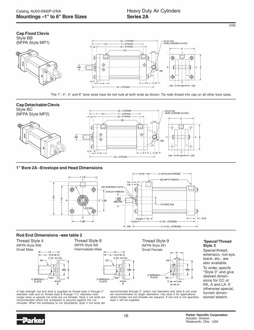
CC
D WRENCHFLATS
MM B
NA
VWA
LA
C
18
KK
D WRENCHFLATS
MM B
NA
V
A
WC
18
KK
D WRENCHFLATS
Rod End Dimensions — see table 2Thread Style 9(NFPA Style SF)Small Female
Thread Style 8(NFPA Style IM)Intermediate Male
Thread Style 4(NFPA Style SM)Small Male
A high strength rod end stud is supplied on thread style 4 through 2"diameter rods and on thread style 8 through 13/8" diameter rods.Larger sizes or special rod ends are cut threads. Style 4 rod ends arerecommended where the workpiece is secured against the rodshoulder. When the workpiece is not shouldered, style 4 rod ends are
recommended through 2" piston rod diameters and style 8 rod endsare recommended on larger diameters. Use style 9 for applicationswhere female rod end threads are required. If rod end is not specified,style 4 will be supplied.
“Special” ThreadStyle 3Special thread,extension, rod eye,blank, etc., arealso available.To order, specify“Style 3” and givedesired dimen-sions for CC orKK, A and LA. Ifotherwise special,furnish dimen-sioned sketch.
Heavy Duty Air CylindersSeries 2A
Parker Hannifin CorporationActuator DivisionWadsworth, Ohio USA
14
C052
Head TrunnionStyle D(NFPA Style MT1)
Cap TrunnionStyle DB(NFPA Style MT2)
Intermediate Fixed TrunnionStyle DD(NFPA Style MT4)
2
R18
4E TD
ETL TL
3
UT
1
G
XG
F J
P + STROKELB + STROKE
ZB + STROKE
W
EE
Y
K
MM
2
R18
4E TD
ETL TL
3
UT
1
G
XJ + STROKE
F J
P + STROKELB + STROKE
ZB + STROKE
W
EE
Y
K
MM
2
R18
4E UV TD
E
TMTL TL
3
UM1
G
XI**
F J
P + STROKELB + STROKE
ZB + STROKE
WEE
Y
K
MM
BD
Catalog AU03-0900P-2/NA
Mountings – 1" to 6" Bore Sizes

Table 1—Envelope and Mounting Dimensions
Table 2—Rod Dimensions
Note: Shaded areas indicate non-standard rod sizes that are available and made to order.
Table 3 — Envelope andMounting Dimensions
* Cushions not available on 1" bore.** On 1", 11/2", 2" and 21/2" bore sizes, the head-end (only) pipe thread is not full depth on cylinders with No. 2 rods. Minimum of three full threads available.
Heavy Duty Air CylindersSeries 2A
15 Parker Hannifin CorporationActuator DivisionWadsworth, Ohio USA
C052
1(Std.)2
1(Std.)2
1(Std.)23
1(Std.)234
1(Std.)234
1(Std.)2345
1(Std.)234567
1(Std.)234567
EE TDBore BD E NPTF F G J K -.001 TL TM UM UT UV LB P
1*11/22
21/2
31/4
456
Rod Style Style +.000Rod Dia. 8 4 & 9 -.002 Min.**
Bore No. MM CC KK A B C D LA NA V W XG XI Y XJ ZB.999
1.1241.1241.4991.1241.9991.4991.1242.3741.4991.9991.4992.6241.9992.3741.4993.1241.9992.3742.6241.4994.2491.9992.3742.6243.1243.7491.9994.7492.3742.6243.1243.7494.249
5/83/43/4
11/83/4
15/8
11/83/42
11/8
15/811/8
21/4
15/82
11/8
315/8
221/411/8
31/2
15/82
21/4
331/2
15/8
42
21/4
331/2
31/2
3/83/83/81/23/85/81/23/83/41/25/81/27/85/83/41/2
15/83/47/81/2
15/83/47/8
11
5/8
13/47/8
111
3/81/2
1/2
7/81/2
11/87/81/2
11/27/8
11/87/8
111/16
11/8
11/27/8
21/16
11/811/2
111/16
7/83
11/8
11/2111/16
21/16
25/811/8
33/8
11/2111/16
21/16
25/83
5/16-247/16-207/16-203/4-16
7/16-201-143/4-16
7/16-2011/4-123/4-161-143/4-16
11/2-121-14
11/4-123/4-16
17/8-121-14
11/4-1211/2-123/4-16
21/2-121-14
11/4-1211/2-1217/8-1221/4-121-143-12
11/4-1211/2-1217/8-1221/4-1221/2-12
11/4
13/813/8
21/8
13/827/8
21/8
13/8
31/2
21/8
27/8
17/8
35/8
25/8
31/4
17/8
45/8
25/8
31/4
35/8
17/8
51/8
25/8
31/4
35/8
45/8
51/8
21/2
51/2
31/8
31/2
41/2
55
7/16
9/16
9/16
15/16
9/16
15/16
15/16
9/16
111/16
15/16
15/16
15/16
115/16
15/16
111/16
15/16
23/8
15/16
111/16
115/16
15/16
33/8
15/16
111/16
115/16
23/8
27/815/16
37/8
111/16
115/16
23/8
27/8
33/8
1/41/41/41/21/45/81/21/43/41/25/81/41/23/81/21/45/83/81/21/21/45/83/81/21/25/85/81/41/23/83/81/21/21/2
5/85/85/8
15/8
11/4
15/8
11/2
111/43/4
13/8
111/43/4
15/8
111/4
13/83/4
15/8
111/4
13/8
15/8
15/87/8
11/2
11/8
11/4
11/2
11/2
11/2
7/16-201/2-201/2-207/8-141/2-2011/4-127/8-141/2-2011/2-127/8-1411/4-127/8-1413/4-1211/4-1211/2-127/8-1421/4-1211/4-1211/2-1213/4-127/8-1431/4-1211/4-1211/2-1213/4-1221/4-1223/4-1211/4-1233/4-1211/2-1213/4-1221/4-1223/4-1231/4-12
Thread
1
11/2
2
21/2
31/4
4
5
6
1/25/85/815/8
13/815/8
13/4
113/8
12
13/8
13/4
121/2
13/8
13/4
21
31/2
13/8
13/4
221/2
313/8
413/4
221/2
331/2
Rod Extensions and Pilot Dimensions Add Stroke
411/16
411/16
47/851/4
415/16
59/16
55/16
51/16
515/16
57/16
511/16
665/8
61/4
61/26
67/8
61/461/2
65/8
65/16
73/16
69/16
613/16
615/16
73/16
73/16
71/16
711/16
75/16
77/16
711/16
711/16
711/16
115/16
115/16
115/16
25/16
115/16
29/16
25/16
115/16
213/16
25/16
29/16
27/16
31/16
211/16
215/16
27/16
35/16
211/16
215/16
31/16
27/16
35/16
211/16
215/16
31/16
35/16
35/16
213/16
37/16
31/16
33/16
37/16
37/16
37/16
13/4
13/4
13/4
21/8
13/4
23/8
21/8
13/4
25/8
21/8
23/8
21/4
27/8
21/2
23/4
21/4
31/8
21/2
23/4
27/8
21/4
31/8
21/2
23/4
27/8
31/8
31/8
25/8
31/4
27/8
331/4
31/4
31/4
••
33/16
39/16
35/16
315/16
311/16
35/16
43/16
311/16
315/16
43/16
413/16
47/16
411/16
43/16
51/16
47/16
411/16
413/16
45/16
51/16
47/16
411/16
413/16
51/16
51/16
415/16
59/16
53/16
55/16
59/16
59/16
59/16
44
41/841/2
41/8
43/441/2
41/4
51/845/8
47/8
555/8
51/4
51/25
57/8
51/451/2
55/8
51/461/8
51/2
53/457/8
61/8
61/857/8
61/2
61/861/4
61/2
61/261/2
■
221/2
333/4
41/2
51/2
61/2
1/43/8**3/8**3/8**
1/21/21/23/4
3/83/83/83/85/85/85/83/4
11/211/211/211/213/4
13/4
13/4
2
1111
11/4
11/4
11/4
11/2
3/16
1/45/16
5/16
3/83/87/16
7/16
.750•1.0001.0001.0001.0001.0001.0001.375
3/4•111111
13/8
•21/2
331/241/2
51/4
61/4
75/8
•41/2
551/2
61/2
71/4
81/4
103/8
34
41/2
553/4
61/2
71/2
91/4
•21/2
331/2
41/4
567
•11/4
11/2
11/2
222
21/2
+.000
37/8
44
41/8
47/847/851/853/4
21/8
21/4
21/4
23/825/825/827/831/8
Add Stroke
•1/41/23/87/87/85/8
11/8
StyleDDMin.
Stroke
• Mounting style DD not available in 1" bore.■1" bore head dimension is 13/4" x 11/2". See page 16 for dimensional information on 1" bore cylinders.
• Mounting style DD not available in 1" bore.**Dimension XI to be specified by customer.
Catalog AU03-0900P-2/NA
Mountings – 1" to 6" Bore Sizes
MM B
NA
VWA
LA
C
18
CC
D WRENCHFLATS
MM B
NA
VWA
LA
C
18
KK
D WRENCHFLATS
MM B
NA
V
A
WC
18
KK
D WRENCHFLATS
Rod End Dimensions — see table 2Thread Style 9(NFPA Style SF)Small Female
Thread Style 8(NFPA Style IM)Intermediate Male
Thread Style 4(NFPA Style SM)Small Male
A high strength rod end stud is supplied on thread style 4 through 2"diameter rods and on thread style 8 through 13/8" diameter rods.Larger sizes or special rod ends are cut threads. Style 4 rod ends arerecommended where the workpiece is secured against the rodshoulder. When the workpiece is not shouldered, style 4 rod ends are
recommended through 2" piston rod diameters and style 8 rod endsare recommended on larger diameters. Use style 9 for applicationswhere female rod end threads are required. If rod end is not specified,style 4 will be supplied.
“Special” ThreadStyle 3Special thread,extension, rod eye,blank, etc., arealso available.To order, specify“Style 3” and givedesired dimen-sions for CC orKK, A and LA. Ifotherwise special,furnish dimen-sioned sketch.
Heavy Duty Air CylindersSeries 2A
Parker Hannifin CorporationActuator DivisionWadsworth, Ohio USA
16
C052
2 4
CB CWCW
3
E
1
G
XC + STROKE
FK
J
P + STROKELB + STROKE
ZC + STROKE
W
EE
Y
L M
CD
PIVOT PINHARD CHROME PLATED
LR
MR
MM E
2 4
CB CWCW
3
E
1
G
XD + STROKE
FK
J F
P + STROKELB + STROKE
ZD + STROKE
W
EE
Y
L M
CD
PIVOT PINHARD CHROME PLATED
LR
MR
MM E
Cap Fixed ClevisStyle BB(NFPA Style MP1)
Cap Detachable ClevisStyle BC(NFPA Style MP2)
The 1", 4", 5" and 6" bore sizes have tie rod nuts at both ends as shown. Tie rods thread into cap on all other bore sizes.
Catalog AU03-0900P-2/NA
Mountings – 1" to 6" Bore Sizes
24
1.08
1.08
1.53 DIA.
3
1 1/2
1 1/
2
1
4 11/16 + STROKE
3 7/8 + STROKE3/8
5/8
5/81
2 1/8 PLUS STROKE
1/4
1/2 ROD DIA.
1/8
5/16-24 THREAD
3/8 ACROSS FLATS
EE NPTF PORTS
1 15/16
3/16
+.000-.002
.999 DIA.
1 1/2
1 3/
4
1" Bore 2A – Envelope and Head Dimensions

Table 1—Envelope and Mounting Dimensions
Table 2—Rod Dimensions
Note: Shaded areas indicate non-standard rod sizes that are available and made to order.
Table 3 — Envelope andMounting Dimensions
* Cushions not available on 1" bore.** On 1", 11/2", 2" and 21/2" bore sizes, the head-end (only) pipe thread is not full depth on cylinders with No. 2 rods. Minimum of three full threads available.
Heavy Duty Air CylindersSeries 2A
17 Parker Hannifin CorporationActuator DivisionWadsworth, Ohio USA
C052
21/8
21/4
21/4
23/825/825/827/831/8
1(Std.)2
1(Std.)2
1(Std.)23
1(Std.)234
1(Std.)234
1(Std.)2345
1(Std.)234567
1(Std.)234567
CD• EEBore CB -.002 CW E NPTF F G J K L LR M MR LB P
† In 1" bore size model only, a single eye mounting, 7/16" thick, is used. Dimension CD (.441") is hole diameter – pin not supplied.• Dimension CD is pin diameter except in 1" bore.
1*11/22
21/2
31/4
456
†
3/43/43/4
11/4
11/4
11/4
11/2
37/8
44
41/8
47/847/851/853/4
■
221/2
333/441/2
51/2
61/2
1/43/8**3/8**3/8**
1/21/21/23/4
3/83/83/83/85/85/85/83/4
11/211/211/211/213/4
13/4
13/42
1111
11/4
11/4
11/411/2
3/16
1/45/16
5/16
3/83/87/16
7/16
+.000
.441†
.501
.501
.501
.751
.751
.7511.001
†
1/21/21/25/85/85/83/4
1/2†
3/43/43/411/4
11/4
11/411/2
1/2†
3/43/43/4111
11/4
7/16†
1/21/21/23/43/43/41
1/2†
5/85/85/8
15/16
15/16
15/16
13/16
■ 1" bore head dimension is 13/4" x 11/2".
Rod Style Style +.000Rod Dia. 8 4 & 9 -.002
Bore No. MM CC KK A B C D LA NA V W Y XC XD ZC ZD.999
1.1241.1241.4991.1241.9991.4991.1242.3741.4991.9991.4992.6241.9992.3741.4993.1241.9992.3742.6241.4994.2491.9992.3742.6243.1243.7491.9994.7492.3742.6243.1243.7494.249
5/83/43/4
11/83/4
15/8
11/83/42
11/8
15/811/8
21/4
15/82
11/8
315/8
221/411/8
31/2
15/82
21/4
331/2
15/8
42
21/4
331/2
31/2
3/83/83/81/2
3/85/81/2
3/83/41/2
5/81/2
7/85/83/41/2
15/83/47/81/2
15/83/47/8
11
5/8
13/47/8
111
3/81/21/27/81/2
11/87/81/2
11/27/8
11/87/8
111/16
11/8
11/27/8
21/16
11/811/2
111/16
7/83
11/8
11/2111/16
21/16
25/811/8
33/8
11/2111/16
21/16
25/83
5/16-247/16-207/16-203/4-16
7/16-201-143/4-16
7/16-2011/4-123/4-161-143/4-16
11/2-121-14
11/4-123/4-16
17/8-121-14
11/4-1211/2-123/4-16
21/2-121-14
11/4-1211/2-1217/8-1221/4-121-143-12
11/4-1211/2-1217/8-1221/4-1221/2-12
11/4
13/813/8
21/8
13/827/8
21/8
13/8
31/2
21/8
27/8
17/8
35/8
25/8
31/4
17/8
45/8
25/8
31/4
35/8
17/8
51/8
25/8
31/4
35/8
45/8
51/8
21/2
51/2
31/8
31/2
41/2
55
7/16
9/16
9/16
15/16
9/16
15/16
15/16
9/16
111/16
15/16
15/16
15/16
115/16
15/16
111/16
15/16
23/8
15/16
111/16
115/16
15/16
33/8
15/16
111/16
115/16
23/8
27/8
15/16
37/8
111/16
115/16
23/8
27/8
33/8
1/41/41/41/21/45/81/21/43/41/25/81/41/23/81/21/45/83/81/21/21/45/83/81/21/25/85/81/41/23/83/81/21/21/2
5/85/85/8
15/8
11/4
15/8
11/2
111/43/4
13/8
111/43/4
15/8
111/4
13/83/4
15/8
111/4
13/8
15/8
15/87/8
11/2
11/8
11/4
11/2
11/2
11/2
7/16-201/2-201/2-207/8-141/2-2011/4-127/8-141/2-2011/2-127/8-1411/4-127/8-1413/4-1211/4-1211/2-127/8-1421/4-1211/4-1211/2-1213/4-127/8-1431/4-1211/4-1211/2-1213/4-1221/4-1223/4-1211/4-1233/4-1211/2-1213/4-1221/4-1223/4-1231/4-12
Thread
1
11/2
2
21/2
31/4
4
5
6
1/25/85/81
5/8
13/81
5/8
13/4
113/8
12
13/8
13/4
121/2
13/8
13/4
21
31/2
13/8
13/4
221/2
313/8
413/4
221/2
331/2
Rod Extensions and Pilot Dimensions Add Stroke
55
53/8
53/4
53/8
653/4
51/2
63/8
57/8
61/8
67/8
71/2
71/8
73/8
67/8
73/4
71/8
73/8
71/2
71/8
873/8
75/8
73/4
88
81/8
83/4
83/8
81/2
83/4
83/4
83/4
57/16
57/16
57/861/4
57/8
61/261/4
667/863/8
65/8
75/881/4
77/8
81/875/8
81/2
77/881/8
81/4
77/883/4
81/8
83/881/2
83/4
83/491/8
93/4
93/891/2
93/4
93/493/4
115/16
115/16
115/16
25/16
115/16
29/16
25/16
115/16
213/16
25/16
29/16
27/16
31/16
211/16
215/16
27/16
35/16
211/16
215/16
31/16
27/16
35/16
211/16
215/16
31/16
35/16
35/16
213/16
37/16
31/16
33/16
37/16
37/16
37/16
53/8
53/8
53/4
61/8
53/4
63/8
61/8
57/8
63/4
61/4
61/2
71/2
81/8
73/4
871/2
83/8
73/4
881/8
73/4
85/8
881/4
83/8
85/8
85/8
87/8
91/2
91/8
91/4
91/2
91/2
91/2
513/16
513/16
61/4
65/8
61/4
67/8
65/8
63/8
71/4
63/4
781/4
87/8
81/2
83/4
81/4
91/8
81/2
83/4
87/8
81/2
93/8
83/4
991/8
93/8
93/8
97/8
101/2
101/8
101/4
101/2
101/2
101/2
Catalog AU03-0900P-2/NA
Mountings – 1" to 6" Bore Sizes
Add Stroke
Heavy Duty Air CylindersSeries 2A
Parker Hannifin CorporationActuator DivisionWadsworth, Ohio USA
18
C052
24E R
R
AA
TTSQ.
3
E1
GWF
BB
F J
P + STROKELB + STROKE
ZB + STROKE
WEE
Y
K
MM
DD
24E TE
TETTSQ.
3
E1
GWF
F J
P + STROKELB + STROKE
ZB + STROKE
WEE
Y
K
MM
EB4 HOLES
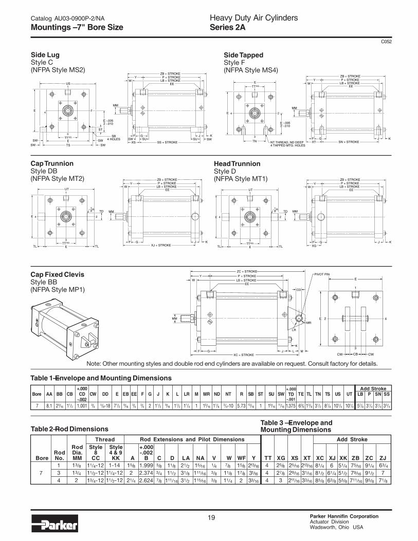
2 4TE E
TE EB4 HOLES
3
E1
GXK + STROKE
FK
J
P + STROKELB + STROKE
ZJ + STROKE
WEE
Y
MM
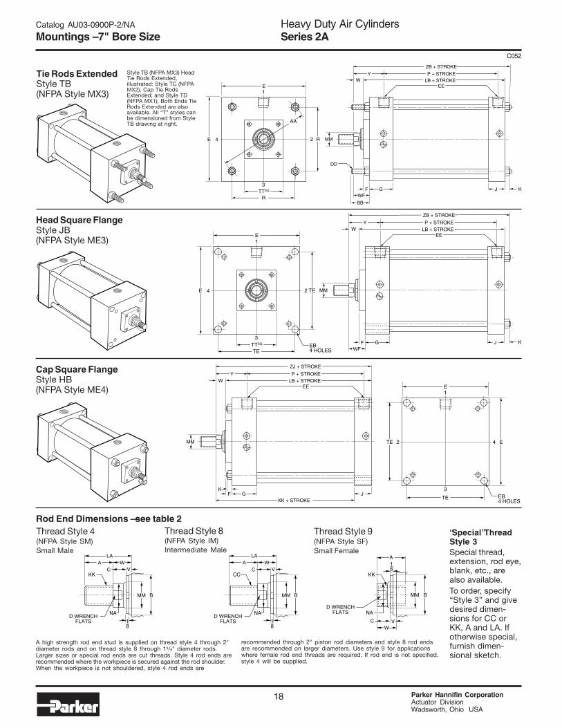
Tie Rods ExtendedStyle TB(NFPA Style MX3)
Head Square FlangeStyle JB(NFPA Style ME3)
Cap Square FlangeStyle HB(NFPA Style ME4)
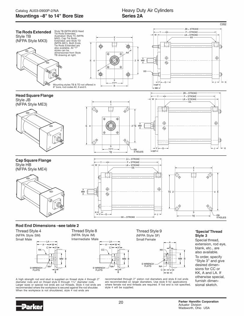
Rod End Dimensions — see table 2Thread Style 9(NFPA Style SF)Small Female
Thread Style 8(NFPA Style IM)Intermediate Male
Thread Style 4(NFPA Style SM)Small Male
A high strength rod end stud is supplied on thread style 4 through 2"diameter rods and on thread style 8 through 13/8" diameter rods.Larger sizes or special rod ends are cut threads. Style 4 rod ends arerecommended where the workpiece is secured against the rod shoulder.When the workpiece is not shouldered, style 4 rod ends are
recommended through 2" piston rod diameters and style 8 rod endsare recommended on larger diameters. Use style 9 for applicationswhere female rod end threads are required. If rod end is not specified,style 4 will be supplied.
“Special” ThreadStyle 3Special thread,extension, rod eye,blank, etc., arealso available.To order, specify“Style 3” and givedesired dimen-sions for CC orKK, A and LA. Ifotherwise special,furnish dimen-sional sketch.
MM B
NA
VWA
LA
C
18
CC
D WRENCHFLATS
MM B
NA
VWA
LA
C
18
KK
D WRENCHFLATS
MM B
NA
V
A
WC
18
KK
D WRENCHFLATS
Style TB (NFPA MX3) HeadTie Rods Extended,illustrated: Style TC (NFPAMX2), Cap Tie RodsExtended; and Style TD(NFPA MX1), Both Ends TieRods Extended are alsoavailable. All “T” styles canbe dimensioned from StyleTB drawing at right.
Catalog AU03-0900P-2/NA
Mountings – 7" Bore Size
Heavy Duty Air CylindersSeries 2A
19 Parker Hannifin CorporationActuator DivisionWadsworth, Ohio USA
C052
134
4E
ST
SW
SWSW
SWTSE
TTSQ.3
US1
GSW SW
XS SS + STROKESU SU
F
P + STROKELB + STROKE
ZB + STROKE
WEE
Y
K
MM
SB4 HOLES
J
2
E -.0052 -.010
24E
TD
E TLTLTTSQ.
3
UT1
XJ + STROKEF
P + STROKELB + STROKE
ZB + STROKE
WEE
Y
K
MM18R
G J
4E
3
E
1
XT SN + STROKEF
P + STROKELB + STROKE
ZB + STROKE
WEE
Y
K
MM
TN
2
NT THREAD, ND DEEP4 TAPPED MTG. HOLES
JG
TTSQ.
E -.0052 -.010
24E
TD
E TLTLTTSQ.
3
UT1
XGF J
P + STROKELB + STROKE
ZB + STROKE
WEE
Y
K
MM18R
G
Rod Style Style +.000Rod Dia. 8 4 & 9 -.002
Bore No. MM CC KK A B C D LA NA V W WF Y TT XG XS XT XC XJ XK ZB ZC ZJ
Thread Add Stroke
13/8
13/42
11/4-1211/2-1213/4-12
1-1411/4-1211/2-12
15/8
221/4
1.9992.3742.624
5/83/47/8
11/8
11/2
111/16
21/231/8
31/2
15/16
111/16
115/16
1/43/83/8
7/811/8
11/4
15/8
17/8
2
213/16
31/16
33/16
444
25/8
27/8
3
25/16
29/16
211/16
213/16
31/16
33/16
Rod Extensions and Pilot Dimensions
781/4
81/2
85/8
661/4
63/8
51/4
51/2
55/8
75/16
79/16
711/16
91/4
91/2
95/8
63/4
771/8
Table 2—Rod Dimensions
+.000Bore AA BB CB CD CW DD E EB EE F G J K L LR M MR ND NT R SB ST SU SW TE TL TN TS US UT LB P SN SS
-.002 7 8.1 25/16 11/2 1.001 3/4 5/8-18 71/2
9/163/4 3/4 2 11/2
9/16 11/2 11/4 1 13/16 11/83/4-10 5.73 13/16 1 19/16
11/16 1.375 63/4 13/8 31/2 87/8 101/4 101/4 57/8 31/4 31/4 33/4
Add Stroke
Table 1—Envelope and Mounting Dimensions
Table 3 — Envelope andMounting Dimensions
Side LugStyle C(NFPA Style MS2)
Cap TrunnionStyle DB(NFPA Style MT2)
Cap Fixed ClevisStyle BB(NFPA Style MP1)
Side TappedStyle F(NFPA Style MS4)
Head TrunnionStyle D(NFPA Style MT1)
E
3
E
1
XC + STROKEF
P + STROKELB + STROKE
ZC + STROKE
WEE
Y
K
MM
CB
2
CW CWJ L MG
4
PIVOT PIN
CD
LR
MR
Note: Other mounting styles and double rod end cylinders are available on request. Consult factory for details.
+.000TD
-.001
Catalog AU03-0900P-2/NA
Mountings – 7" Bore Size
Heavy Duty Air CylindersSeries 2A
Parker Hannifin CorporationActuator DivisionWadsworth, Ohio USA
20
C052
24E R
R
AA
TTSQ.
3
E1
GWF
BB
F J
P + STROKELB + STROKE
ZB + STROKE
WEE
Y
K
MM
DD
24E TE
TETTSQ.
3
E1
GWF
F J
P + STROKELB + STROKE
ZB + STROKE
WEE
Y
K
MM
EB4 HOLES
2 4TE E
TE EB4 HOLES
3
E1
GXK + STROKE
FK
J
P + STROKELB + STROKE
ZJ + STROKE
WEE
Y
MM
Tie Rods ExtendedStyle TB(NFPA Style MX3)
Head Square FlangeStyle JB(NFPA Style ME3)
Cap Square FlangeStyle HB(NFPA Style ME4)
Style TB (NFPA MX3) HeadTie Rods Extended,illustrated: Style TC (NFPAMX2), Cap Tie RodsExtended; and Style TD(NFPA MX1), Both EndsTie Rods Extended arealso available. All “T”styles can bedimensioned from StyleTB drawing at right.
Rod End Dimensions — see table 2Thread Style 9(NFPA Style SF)Small Female
Thread Style 8(NFPA Style IM)Intermediate Male
Thread Style 4(NFPA Style SM)Small Male
“Special’ ThreadStyle 3Special thread,extension, rod eye,blank, etc., arealso available.To order, specify“Style 3” and givedesired dimen-sions for CC orKK, A and LA. Ifotherwise special,furnish dimen-sional sketch.
MM B
NA
VWA
LA
C
18
CC
D WRENCHFLATS
MM B
NA
VWA
LA
C
18
KK
D WRENCHFLATS
MM B
NA
V
A
WC
18
KK
D WRENCHFLATS
Mounting styles TB & TD not offered in8" bore, rod codes #2, 9 and 0.
A high strength rod end stud is supplied on thread style 4 through 2"diameter rods and on thread style 8 through 13/8" diameter rods.Larger sizes or special rod ends are cut threads. Style 4 rod ends arerecommended where the workpiece is secured against the rod shoulder.When the workpiece is not shouldered, style 4 rod ends are
recommended through 2" piston rod diameters and style 8 rod endsare recommended on larger diameters. Use style 9 for applicationswhere female rod end threads are required. If rod end is not specified,style 4 will be supplied.
Catalog AU03-0900P-2/NA
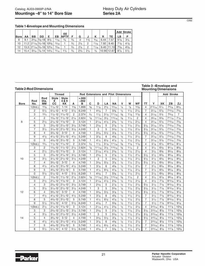
Mountings – 8" to 14" Bore Size
Heavy Duty Air CylindersSeries 2A
21 Parker Hannifin CorporationActuator DivisionWadsworth, Ohio USA
C052
EEBore AA BB DD E EB NPTF F G J K R TE LB P
Rod Style Style +.000Rod Dia. 8 4 & 9 -.002
Bore No. MM CC KK A B C D LA NA V W WF TT Y XK ZB ZJ1.9996.2492.3742.6243.1243.7494.2494.7495.2495.7492.3742.6243.1243.7494.2494.7495.2495.7496.2492.6243.1243.7494.2494.7495.2495.7496.2493.1243.7494.2494.7495.2495.7496.249
15/8
51/2
221/4
331/2
31/2
441/2
52
21/4
331/231/2
441/25
51/2
21/43
31/2
31/24
41/2
551/2
331/231/2
441/25
51/2
5/8
13/47/8
111111
3/47/8
11111117/8
11111111111111
11/8
45/8
11/2111/16
21/16
25/83
33/8
37/841/4
11/2
111/16
21/16
25/8
333/8
37/8
41/445/8
111/16
21/16
25/8
333/837/8
41/4
45/821/16
25/8
333/8
37/8
41/445/8
1-144-12
11/4-1211/2-1217/8-1221/4-1221/2-123-12
31/4-1231/2-1211/4-1211/2-1217/8-1221/4-1221/2-123-12
31/4-1231/2-124-12
11/2-1217/8-1221/4-1221/2-123-12
31/4-1231/2-124-12
17/8-1221/4-1221/2-123-12
31/4-1231/2-124-12
21/2
731/8
31/2
41/255
51/2
661/2
31/8
31/2
41/2
55
51/2
661/2
731/2
41/2
55
51/2
661/2
741/2
55
51/2
661/2
7
15/16
53/8111/16
115/16
23/827/8
33/8
37/8
43/8
47/8
111/16
115/16
23/8
27/8
33/8
37/8
43/8
47/8
53/8
115/16
23/8
27/8
33/8
37/8
43/8
47/8
53/8
23/8
27/8
33/8
37/8
43/8
47/8
53/8
1/41/23/83/81/21/21/21/21/21/23/83/81/21/21/21/21/21/21/23/81/21/21/21/21/21/21/21/21/21/21/21/21/21/2
7/8
11/211/8
11/4
11/211/2
11/2
11/2
11/2
11/2
11/8
11/4
11/2
11/2
11/2
11/2
11/2
11/2
11/2
11/4
11/2
11/2
11/2
11/2
11/2
11/2
11/2
11/2
11/2
11/2
11/2
11/2
11/2
11/2
47444
51/251/2
51/2
77444
51/2
51/251/2
77744
51/2
51/2
51/27774
51/2
51/251/2
777
11/4-1251/4-1211/2-1213/4-1221/4-1223/4-1231/4-1233/4-1241/4-1243/4-1211/2-1213/4-1221/4-1223/4-1231/4-1233/4-1241/4-1243/4-1251/4-1213/4-1221/4-1223/4-1231/4-1233/4-1241/4-1243/4-1251/4-1221/4-1223/4-1231/4-1233/4-1241/4-1243/4-1251/4-12
Thread
13/8
51/2
13/42
21/2
331/2
441/2
513/4
221/2
331/2
441/2
551/2
221/2
331/2
441/2
551/2
21/2
331/2
441/2
551/2
Rod Extensions and Pilot Dimensions
63/4
73/8
771/8
73/8
73/8
73/8
73/8
73/8
73/8
81/4
83/8
85/8
85/8
85/8
85/8
85/8
85/8
85/8
87/8
91/8
91/8
91/8
91/8
91/8
91/8
91/8
103/8
103/8
103/8
103/8
103/8
103/8
103/8
8
10
12
14
9.111.213.315.4
25/16
211/16
211/16
33/16
5/8-183/4-163/4-167/8-14
81/2105/8123/4
143/4
11/16
13/16
13/16
15/16
3/4
11
11/4
3/43/43/43/4
221/4
21/4
23/4
11/222
21/4
9/16
11/16
11/16
3/4
6.447.929.4010.90
7.579.40
11.1012.87
57/871/875/887/8
31/4
41/8 45/8 51/2
8101214
51/4
57/8
51/2
55/8
57/8
57/8
57/8
57/8
57/8
57/8
61/4
63/8
65/8
65/8
65/8
65/8
65/8
65/8
65/8
67/8
71/8
71/8
71/8
71/8
71/8
71/8
71/8
81/8
81/8
81/8
81/8
81/8
81/8
81/8
75/16
715/16
79/16
711/16
715/16
715/16
715/16
715/16
715/16
715/16
815/16
91/16
95/16
95/16
95/16
95/16
95/16
95/16
95/16
99/16
913/16
913/16
913/16
913/16
913/16
913/16
913/16
111/8111/8
111/8
111/8111/8
111/8
111/8
Add Stroke
15/8
21/4
17/8
221/4
21/4
21/4
21/4
21/4
21/4
17/8
221/4
21/4
21/4
21/4
21/4
21/4
21/4
221/4
21/4
21/4
21/4
21/4
21/4
21/4
21/4
21/4
21/4
21/4
21/4
21/4
21/4
213/16
37/16
31/16
33/16
37/16
37/16
37/16
37/16
37/16
37/16
31/831/4
31/2
31/231/2
31/2
31/231/2
31/2
31/431/2
31/2
31/231/2
31/2
31/231/2
313/16
313/16
313/16
313/16
313/16
313/16
313/16
Table 1—Envelope and Mounting Dimensions
Table 2—Rod DimensionsTable 3 — Envelope andMounting Dimensions
1(Std.)234567890
1(Std.)34567890
1(Std.)3456789
1(Std.)345678
Add Stroke
Catalog AU03-0900P-2/NA
Mountings – 8" to 14" Bore Size
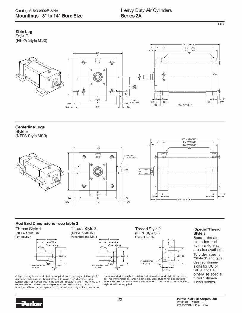
Heavy Duty Air CylindersSeries 2A
Parker Hannifin CorporationActuator DivisionWadsworth, Ohio USA
22
C052
4E
ST
SW
SW
SW
SWTS
ETTSQ.
3
US1
GSW SW
XS SS + STROKE
SU SUF
P + STROKELB + STROKE
ZB + STROKE
WEE
Y
K
MM
SB4 HOLES
J
2
E –.0052 –.010
24E
ST
SW
SW
SW
SWTS
ETTSQ.
3
US1
GSW SW
XS SS + STROKE
SU SUF
P + STROKELB + STROKE
ZB + STROKE
WEE
Y
K
MM
SB4 HOLES
J
Side LugStyle C(NFPA Style MS2)
Centerline LugsStyle E(NFPA Style MS3)
Rod End Dimensions — see table 2Thread Style 9(NFPA Style SF)Small Female
Thread Style 8(NFPA Style IM)Intermediate Male
Thread Style 4(NFPA Style SM)Small Male
“Special” ThreadStyle 3Special thread,extension, rodeye, blank, etc.,are also available.To order, specify“Style 3” and givedesired dimen-sions for CC orKK, A and LA. Ifotherwise special,furnish dimen-sional sketch.
MM B
NA
VWA
LA
C
18
CC
D WRENCHFLATS
MM B
NA
VWA
LA
C
18
KK
D WRENCHFLATS
MM B
NA
V
A
WC
18
KK
D WRENCHFLATS
A high strength rod end stud is supplied on thread style 4 through 2"diameter rods and on thread style 8 through 13/8" diameter rods.Larger sizes or special rod ends are cut threads. Style 4 rod ends arerecommended where the workpiece is secured against the rodshoulder. When the workpiece is not shouldered, style 4 rod ends are
recommended through 2" piston rod diameters and style 8 rod endsare recommended on larger diameters. Use style 9 for applicationswhere female rod end threads are required. If rod end is not specified,style 4 will be supplied.
Catalog AU03-0900P-2/NA
Mountings – 8" to 14" Bore Size
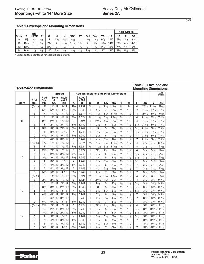
Heavy Duty Air CylindersSeries 2A
23 Parker Hannifin CorporationActuator DivisionWadsworth, Ohio USA
C052
1(Std.)234567890
1(Std.)34567890
1(Std.)3456789
1(Std.)345678
EEBore E NPTF F G J K SB* ST SU SW TS US LB P SS
97/8123/8141/217
111/4141/8161/4191/4
57/871/875/887/8
31/4
41/845/851/2
8101214
Add Stroke
Rod Style Style +.000Rod Dia. 8 4 & 9 -.002
Bore No. MM CC KK A B C D LA NA V W TT XS Y ZB1.9996.2492.3742.6243.1243.7494.2494.7495.2495.7492.3742.6243.1243.7494.2494.7495.2495.7496.2492.6243.1243.7494.2494.7495.2495.7496.2493.1243.7494.2494.7495.2495.7496.249
15/8
51/2
221/4
331/2
31/2
441/2
52
21/4
331/2
31/2
441/2
551/2
21/4
331/2
31/2
441/2
551/2
331/2
31/2
441/2
551/2
5/8
13/47/8
111111
3/47/8
11111117/8
11111111111111
11/8
45/8
11/2
111/16
21/16
25/8
333/8
37/8
41/4
11/2
111/16
21/16
25/8
333/8
37/8
41/4
45/8
111/16
21/16
25/8
333/8
37/8
41/4
45/8
21/16
25/8
333/8
37/8
41/4
45/8
1-144-12
11/4-1211/2-1217/8-1221/4-1221/2-123-12
31/4-1231/2-1211/4-1211/2-1217/8-1221/4-1221/2-123-12
31/4-1231/2-124-12
11/2-1217/8-1221/4-1221/2-123-12
31/4-1231/2-124-12
17/8-1221/4-1221/2-123-12
31/4-1231/2-124-12
21/2
731/8
31/2
41/2
55
51/2
661/2
31/8
31/2
41/2
55
51/2
661/2
731/2
41/2
55
51/2
661/2
741/2
55
51/2
661/2
7
15/16
53/8
111/16
115/16
23/8
27/8
33/8
37/8
43/8
47/8
111/16
115/16
23/8
27/8
33/8
37/8
43/8
47/8
53/8
115/16
23/8
27/8
33/8
37/8
43/8
47/8
53/8
23/8
27/8
33/8
37/8
43/8
47/8
53/8
1/41/23/83/81/21/21/21/21/21/23/83/81/21/21/21/21/21/21/23/81/21/21/21/21/21/21/21/21/21/21/21/21/21/2
7/8
11/2
11/8
11/4
11/2
11/2
11/2
11/2
11/2
11/2
11/8
11/4
11/2
11/2
11/2
11/2
11/2
11/2
11/2
11/4
11/2
11/2
11/2
11/2
11/2
11/2
11/2
11/2
11/2
11/2
11/2
11/2
11/2
11/2
47444
51/2
51/2
51/2
77444
51/2
51/2
51/2
77744
51/2
51/2
51/2
7774
51/2
51/2
51/2
777
11/4-1251/4-1211/2-1213/4-1221/4-1223/4-1231/4-1233/4-1241/4-1243/4-1211/2-1213/4-1221/4-1223/4-1231/4-1233/4-1241/4-1243/4-1251/4-1213/4-1221/4-1223/4-1231/4-1233/4-1241/4-1243/4-1251/4-1221/4-1223/4-1231/4-1233/4-1241/4-1243/4-1251/4-12
Thread
13/8
51/2
13/4
221/2
331/2
441/2
513/4
221/2
331/2
441/2
551/2
221/2
331/2
441/2
551/2
21/2
331/2
441/2
551/2
Rod Extensions and Pilot Dimensions AddStroke
8
10
12
14
Table 1—Envelope and Mounting Dimensions
Table 2—Rod DimensionsTable 3 — Envelope andMounting Dimensions
213/16
37/16
31/16
33/16
37/16
37/16
37/16
37/16
37/16
37/16
31/8
31/4
31/2
31/2
31/2
31/2
31/2
31/2
31/2
31/4
31/2
31/2
31/2
31/2
31/2
31/2
31/2
313/16
313/16
313/16
313/16
313/16
313/16
313/16
75/16
715/16
79/16
711/16
715/16
715/16
715/16
715/16
715/16
715/16
815/16
91/16
95/16
95/16
95/16
95/16
95/16
95/16
95/16
99/16
913/16
913/16
913/16
913/16
913/16
913/16
913/16
111/8
111/8
111/8
111/8
111/8
111/8
111/8
25/16
215/16
29/16
211/16
215/16
215/16
215/16
215/16
215/16
215/16
23/4
27/8
31/8
31/8
31/8
31/8
31/8
31/8
31/8
27/8
31/8
31/8
31/8
31/8
31/8
31/8
31/8
33/8
33/8
33/8
33/8
33/8
33/8
33/8
81/2105/8123/4
143/4
3/4
11
11/4
3/43/43/43/4
221/4
21/4
23/4
11/222
21/4
9/16
11/16
11/16
3/4
13/16
11/16
11/16
15/16
111/4
11/4
11/2
19/16
22
21/2
11/16
7/87/8
11/8
33/4
45/851/857/8
* Upper surface spotfaced for socket head screws.
Catalog AU03-0900P-2/NA
Mountings – 8" to 14" Bore Size
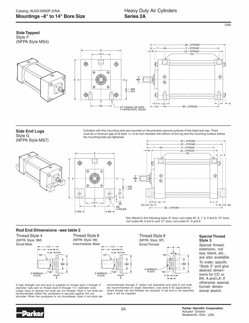
Heavy Duty Air CylindersSeries 2A
Parker Hannifin CorporationActuator DivisionWadsworth, Ohio USA
24
C052
Catalog AU03-0900P-2/NA
Mountings – 8" to 14" Bore Size
4E
3
E
1
XT SN + STROKEF
P + STROKELB + STROKE
ZB + STROKE
WEE
Y
K
MM
TN
2
E —.0052 —.010
NT THREAD, ND DEEP4 TAPPED MTG. HOLES
TTSQ.
JG
Side TappedStyle F(NFPA Style MS4)
Side End LugsStyle G(NFPA Style MS7)
Not offered in the following sizes: 8" bore, rod codes #2, 6, 7, 8, 9 and 0; 10" bore,rod codes #8, 9 and 0; and 12" bore, rod codes #7, 8 and 9.
Cylinders with this mounting style are mounted on the precision ground surfaces of the head and cap. Theremust be a minimum gap of at least 1/64 of an inch between the bottom of the lug and the mounting surface beforethe mounting bolts are tightened.
Rod End Dimensions — see table 2Thread Style 9(NFPA Style SF)Small Female
Thread Style 8(NFPA Style IM)Intermediate Male
Thread Style 4(NFPA Style SM)Small Male
Special ThreadStyle 3Special thread,extension, rodeye, blank, etc.,are also available.To order, specify“Style 3” and givedesired dimen-sions for CC orKK, A and LA. Ifotherwise special,furnish dimen-sional sketch.
MM B
NA
VWA
LA
C
18
CC
D WRENCHFLATS
MM B
NA
VWA
LA
C
18
KK
D WRENCHFLATS
MM B
NA
V
A
WC
18
KK
D WRENCHFLATS
24E
ET
164
E2
R EB4 HOLES
TTSQ.
3
E1
GELEL EOEO
SE + STROKE
F J
P + STROKELB + STROKE
XE + STROKEZE + STROKE
WEE
Y
K
MM
—.005—.010
ESES
A high strength rod end stud is supplied on thread style 4 through 2"diameter rods and on thread style 8 through 13/8" diameter rods.Larger sizes or special rod ends are cut threads. Style 4 rod ends arerecommended where the workpiece is secured against the rodshoulder. When the workpiece is not shouldered, style 4 rod ends are
recommended through 2" piston rod diameters and style 8 rod endsare recommended on larger diameters. Use style 9 for applicationswhere female rod end threads are required. If rod end is not specified,style 4 will be supplied.
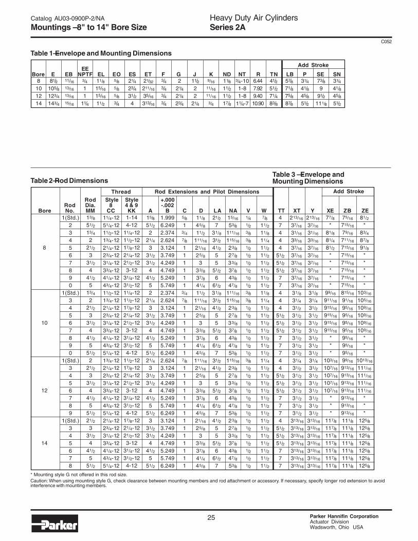
Heavy Duty Air CylindersSeries 2A
25 Parker Hannifin CorporationActuator DivisionWadsworth, Ohio USA
C052
Catalog AU03-0900P-2/NA
Mountings – 8" to 14" Bore Size
1(Std.)234567890
1(Std.)34567890
1(Std.)3456789
1(Std.)345678
* Mounting style G not offered in this rod size.Caution: When using mounting style G, check clearance between mounting members and rod attachment or accessory. If necessary, specify longer rod extension to avoidinterference with mounting members.
Rod Style Style +.000Rod Dia. 8 4 & 9 -.002
Bore No. MM CC KK A B C D LA NA V W TT XT Y XE ZB ZE1.9996.2492.3742.6243.1243.7494.2494.7495.2495.7492.3742.6243.1243.7494.2494.7495.2495.7496.2492.6243.1243.7494.2494.7495.2495.7496.2493.1243.7494.2494.7495.2495.7496.249
15/8
51/2
221/4
331/2
31/2
441/2
52
21/4
331/2
31/2
441/2
551/2
21/4
331/2
31/2
441/2
551/2
331/2
31/2
441/2
551/2
5/8
13/47/8
111111
3/47/8
1111111
7/8
11111111111111
11/8
45/8
11/2
111/16
21/16
25/8
333/8
37/8
41/4
11/2
111/16
21/16
25/8
333/8
37/8
41/4
45/8
111/16
21/16
25/8
333/8
37/8
41/4
45/8
21/16
25/8
333/8
37/8
41/4
45/8
1-144-12
11/4-1211/2-1217/8-1221/4-1221/2-123-12
31/4-1231/2-1211/4-1211/2-1217/8-1221/4-1221/2-123-12
31/4-1231/2-124-12
11/2-1217/8-1221/4-1221/2-123-12
31/4-1231/2-124-12
17/8-1221/4-1221/2-123-12
31/4-1231/2-124-12
21/2
731/8
31/2
41/2
55
51/2
661/2
31/8
31/2
41/2
55
51/2
661/2
731/2
41/2
55
51/2
661/2
741/2
55
51/2
661/2
7
15/16
53/8
111/16
115/16
23/8
27/8
33/8
37/8
43/8
47/8
111/16
115/16
23/8
27/8
33/8
37/8
43/8
47/8
53/8
115/16
23/8
27/8
33/8
37/8
43/8
47/8
53/8
23/8
27/8
33/8
37/8
43/8
47/8
53/8
1/41/23/83/81/21/21/21/21/21/23/83/81/21/21/21/21/21/21/23/81/21/21/21/21/21/21/21/21/21/21/21/21/21/2
7/8
11/2
11/8
11/4
11/2
11/2
11/2
11/2
11/2
11/2
11/8
11/4
11/2
11/2
11/2
11/2
11/2
11/2
11/2
11/4
11/2
11/2
11/2
11/2
11/2
11/2
11/2
11/2
11/2
11/2
11/2
11/2
11/2
11/2
47444
51/2
51/2
51/2
77444
51/2
51/2
51/2
77744
51/2
51/2
51/2
7774
51/2
51/2
51/2
777
11/4-1251/4-1211/2-1213/4-1221/4-1223/4-1231/4-1233/4-1241/4-1243/4-1211/2-1213/4-1221/4-1223/4-1231/4-1233/4-1241/4-1243/4-1251/4-1213/4-1221/4-1223/4-1231/4-1233/4-1241/4-1243/4-1251/4-1221/4-1223/4-1231/4-1233/4-1241/4-1243/4-1251/4-12
Thread
13/8
51/2
13/4
221/2
331/2
441/2
513/4
221/2
331/2
441/2
551/2
221/2
331/2
441/2
551/2
21/2
331/2
441/2
551/2
Rod Extensions and Pilot Dimensions
8
10
12
14
EEBore E EB NPTF EL EO ES ET F G J K ND NT R TN LB P SE SN
41/251/271/483/8
8101214
Table 1—Envelope and Mounting Dimensions
Table 2—Rod DimensionsTable 3 — Envelope andMounting Dimensions
Add Stroke
57/871/875/887/8
31/4
41/845/851/2
81/2105/8123/4
143/4
3/4
11
11/4
3/43/43/43/4
221/4
21/4
23/4
11/222
21/4
9/16
11/16
11/16
3/4
11/16
13/16
13/16
15/16
6.447.929.4010.90
11/8
15/16
15/16
11/2
5/85/85/83/4
21/4
23/431/24
21/32
211/16
35/16
313/16
11/8
11/211/217/8
3/4-101-81-8
11/4-7
73/89
91/2111/8
31/4
41/845/851/2
213/16
37/16
31/16
33/16
37/16
37/16
37/16
37/16
37/16
37/16
31/8
31/4
31/2
31/2
31/2
31/2
31/2
31/2
31/2
31/4
31/2
31/2
31/2
31/2
31/2
31/2
31/2
313/16
313/16
313/16
313/16
313/16
313/16
313/16
81/2
*83/4
87/8
91/8
*****
103/16
105/16
109/16
109/16
109/16
109/16
***
1013/16
111/16
111/16
111/16
111/16
***
125/8
125/8
125/8
125/8
125/8
125/8
125/8
213/16
37/16
31/16
33/16
37/16
37/16
37/16
37/16
37/16
37/16
31/8
31/4
31/2
31/2
31/2
31/2
31/2
31/2
31/2
31/4
31/2
31/2
31/2
31/2
31/2
31/2
31/2
313/16
313/16
313/16
313/16
313/16
313/16
313/16
75/16
715/16
79/16
711/16
715/16
715/16
715/16
715/16
715/16
715/16
815/16
91/16
95/16
95/16
95/16
95/16
95/16
95/16
95/16
99/16
913/16
913/16
913/16
913/16
913/16
913/16
913/16
111/8
111/8
111/8
111/8
111/8
111/8
111/8
77/8
*81/8
81/4
81/2
*****
99/16
911/16
915/16
915/16
915/16
915/16
***
103/16
107/16
107/16
107/16
107/16
***
117/8
117/8
117/8
117/8
117/8
117/8
117/8
Add Stroke
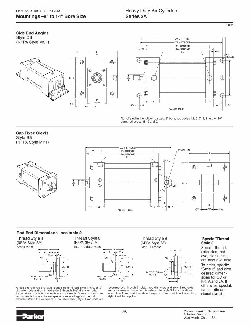
Heavy Duty Air CylindersSeries 2A
Parker Hannifin CorporationActuator DivisionWadsworth, Ohio USA
26
C052
Catalog AU03-0900P-2/NA
Mountings – 8" to 14" Bore Size
Side End AnglesStyle CB(NFPA Style MS1)
Cap Fixed ClevisStyle BB(NFPA Style MP1)
Not offered in the following sizes: 8" bore, rod codes #2, 6, 7, 8, 9 and 0; 10"bore, rod codes #8, 9 and 0.
Rod End Dimensions — see table 2Thread Style 9(NFPA Style SF)Small Female
Thread Style 8(NFPA Style IM)Intermediate Male
Thread Style 4(NFPA Style SM)Small Male
“Special” ThreadStyle 3Special thread,extension, rodeye, blank, etc.,are also available.To order, specify“Style 3” and givedesired dimen-sions for CC orKK, A and LA. Ifotherwise special,furnish dimen-sional sketch.
4
3E
AHAT TTSQ.
2
E
1
SA + STROKE
F
P + STROKELB + STROKE
XA + STROKE
ZA + STROKE
WEE
Y
K
MM S
GALAO
JAL AO
ATAB 6HOLES
MM B
NA
VWA
LA
C
18
CC
D WRENCHFLATS
MM B
NA
VWA
LA
C
18
KK
D WRENCHFLATS
MM B
NA
V
A
WC
18
KK
D WRENCHFLATS
E
3
E
1
XC + STROKEF
P + STROKELB + STROKE
ZC + STROKE
WEE
Y
K
MM
CB
2
CW CWJ L MG
4
PIVOT PIN
CD
LR
MR
A high strength rod end stud is supplied on thread style 4 through 2"diameter rods and on thread style 8 through 13/8" diameter rods.Larger sizes or special rod ends are cut threads. Style 4 rod ends arerecommended where the workpiece is secured against the rodshoulder. When the workpiece is not shouldered, style 4 rod ends are
recommended through 2" piston rod diameters and style 8 rod endsare recommended on larger diameters. Use style 9 for applicationswhere female rod end threads are required. If rod end is not specified,style 4 will be supplied.

Heavy Duty Air CylindersSeries 2A
27 Parker Hannifin CorporationActuator DivisionWadsworth, Ohio USA
C052
Catalog AU03-0900P-2/NA
Mountings – 8" to 14" Bore Size
1(Std.)234567890
1(Std.)34567890
1(Std.)3456789
1(Std.)345678
Table 1—Envelope and Mounting Dimensions
Table 2—Rod DimensionsTable 3 — Envelope andMounting Dimensions
* CD is pin diameter.
Rod Style Style +.000Rod Dia. 8 4 & 9 -.002
Bore No. MM CC KK A B C D LA NA V W TT Y XA XC ZA ZC1.9996.2492.3742.6243.1243.7494.2494.7495.2495.7492.3742.6243.1243.7494.2494.7495.2495.7496.2492.6243.1243.7494.2494.7495.2495.7496.2493.1243.7494.2494.7495.2495.7496.249
15/8
51/2
221/4
331/2
31/2
441/2
52
21/4
331/2
31/2
441/2
551/2
21/4
331/2
31/2
441/2
551/2
331/2
31/2
441/2
551/2
5/8
13/47/8
111111
3/47/8
1111111
7/8
11111111111111
11/8
45/8
11/2
111/16
21/16
25/8
333/8
37/8
41/4
11/2
111/16
21/16
25/8
333/8
37/8
41/4
45/8
111/16
21/16
25/8
333/8
37/8
41/4
45/8
21/16
25/8
333/8
37/8
41/4
45/8
1-144-12
11/4-1211/2-1217/8-1221/4-1221/2-123-12
31/4-1231/2-1211/4-1211/2-1217/8-1221/4-1221/2-123-12
31/4-1231/2-124-12
11/2-1217/8-1221/4-1221/2-123-12
31/4-1231/2-124-12
17/8-1221/4-1221/2-123-12
31/4-1231/2-124-12
21/2
731/8
31/2
41/2
55
51/2
661/2
31/8
31/2
41/2
55
51/2
661/2
731/2
41/2
55
51/2
661/2
741/2
55
51/2
661/2
7
15/16
53/8
111/16
115/16
23/8
27/8
33/8
37/8
43/8
47/8
111/16
115/16
23/8
27/8
33/8
37/8
43/8
47/8
53/8
115/16
23/8
27/8
33/8
37/8
43/8
47/8
53/8
23/8
27/8
33/8
37/8
43/8
47/8
53/8
1/41/23/83/81/21/21/21/21/21/23/83/81/21/21/21/21/21/21/23/81/21/21/21/21/21/21/21/21/21/21/21/21/21/2
7/8
11/2
11/8
11/4
11/2
11/2
11/2
11/2
11/2
11/2
11/8
11/4
11/2
11/2
11/2
11/2
11/2
11/2
11/2
11/4
11/2
11/2
11/2
11/2
11/2
11/2
11/2
11/2
11/2
11/2
11/2
11/2
11/2
11/2
47444
51/2
51/2
51/2
77444
51/2
51/2
51/2
77744
51/2
51/2
51/2
7774
51/2
51/2
51/2
777
213/16
37/16
31/16
33/16
37/16
37/16
37/16
37/16
37/16
37/16
31/8
31/4
31/2
31/2
31/2
31/2
31/2
31/2
31/2
31/4
31/2
31/2
31/2
31/2
31/2
31/2
31/2
313/16
313/16
313/16
313/16
313/16
313/16
313/16
11/4-1251/4-1211/2-1213/4-1221/4-1223/4-1231/4-1233/4-1241/4-1243/4-1211/2-1213/4-1221/4-1223/4-1231/4-1233/4-1241/4-1243/4-1251/4-1213/4-1221/4-1223/4-1231/4-1233/4-1241/4-1243/4-1251/4-1221/4-1223/4-1231/4-1233/4-1241/4-1243/4-1251/4-12
Thread
13/8
51/2
13/4
221/2
331/2
441/2
513/4
221/2
331/2
441/2
551/2
221/2
331/2
441/2
551/2
21/2
331/2
441/2
551/2
Rod Extensions and Pilot Dimensions
91/4
97/8
91/2
95/8
97/8
97/8
97/8
97/8
97/8
97/8
113/4
117/8
121/8
121/8
121/8
121/8
121/8
121/8
121/8
127/8
131/8
131/8
131/8
131/8
131/8
131/8
131/8
147/8
147/8
147/8
147/8
147/8
147/8
147/8
89/16
*813/16
815/16
93/16
*****
103/8
101/2
103/4
103/4
103/4
103/4
***
11111/4
111/4
111/4
111/4
111/4
111/4
111/4
1213/16
1213/16
1213/16
1213/16
1213/16
1213/16
1213/16
Add Stroke
8
10
12
14
81/4
87/8
81/2
85/8
87/8
87/8
87/8
87/8
87/8
87/8
103/8
101/2
103/4
103/4
103/4
103/4
103/4
103/4
103/4
111/8
113/8
113/8
113/8
113/8
113/8
113/8
113/8
127/8
127/8
127/8
127/8
127/8
127/8
127/8
91/4
*91/2
95/8
97/8
*****
111/4
113/8
115/8
115/8
115/8
115/8
***
117/8
121/8
121/8
121/8
121/8
121/8
121/8
121/8
137/8
137/8
137/8
137/8
137/8
137/8
137/8
+.000CD* EE
Bore AB AH AL AO AT CB -.002 CW E NPTF F G J K L LR M MR S LB P SA
Add Stroke
13/16
11/16
11/16
15/16
41/4
55/16
63/873/8
113/16
21/821/827/16
11/16
7/87/8
11/16
1/41/43/83/8
11/22
21/2
21/2
1.0011.3761.7512.001
3/4
111/411/4
81/2105/8123/4
143/4
3/4
11
11/4
3/43/43/43/4
221/4
21/4
23/4
11/222
21/4
9/16
11/16
11/16
3/4
11/221/821/421/2
11/4
17/821/823/8
113/813/4
2
13/16
15/8
21/8
23/8
71/887/811
125/8
57/871/875/887/8
31/4
41/845/851/2
83/4
105/8111/813
8101214
* Mounting style G not offered in this rod size.Caution: When using mounting style G, check clearance between mounting members and rod attachment or accessory. If necessary, specify longer rod extension toavoid interference with mounting members.
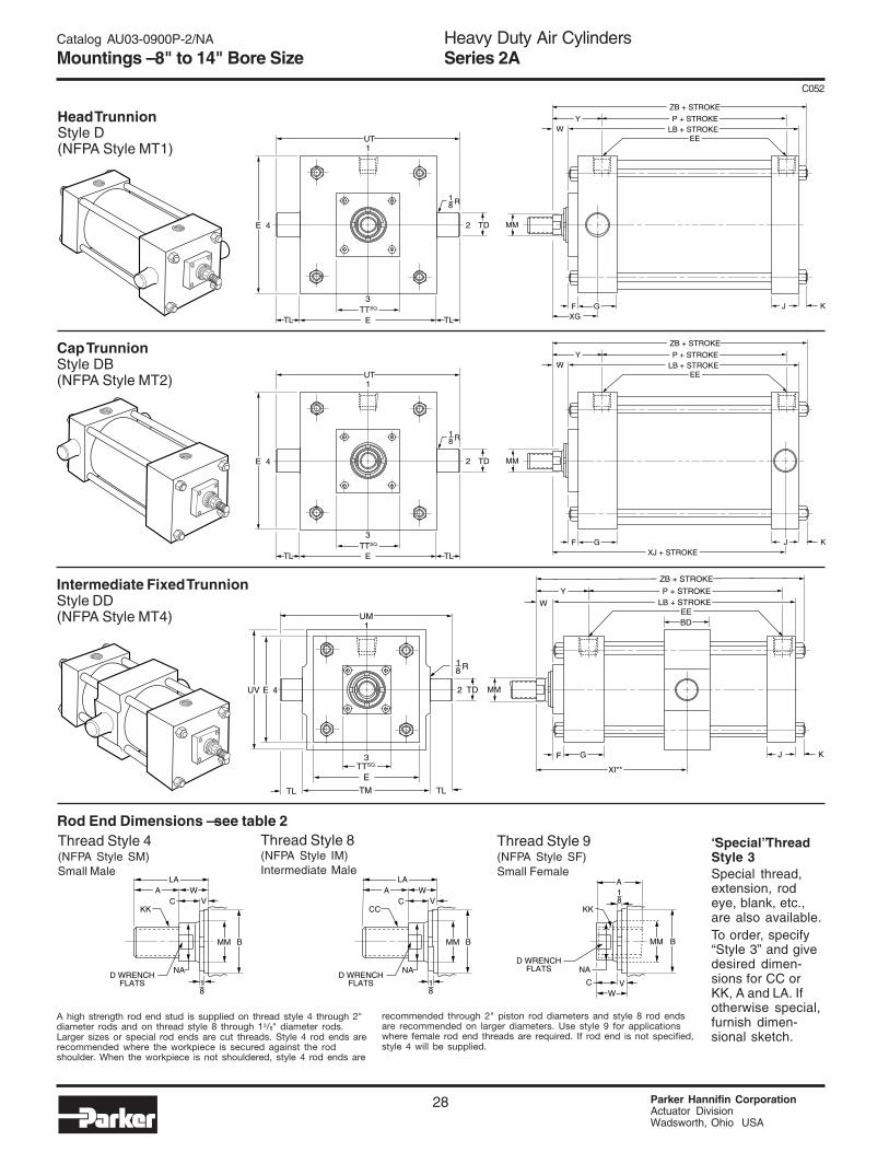
Heavy Duty Air CylindersSeries 2A
Parker Hannifin CorporationActuator DivisionWadsworth, Ohio USA
28
C052
Catalog AU03-0900P-2/NA
Mountings – 8" to 14" Bore Size
Head TrunnionStyle D(NFPA Style MT1)
Cap TrunnionStyle DB(NFPA Style MT2)
Intermediate Fixed TrunnionStyle DD(NFPA Style MT4)
Rod End Dimensions — see table 2Thread Style 9(NFPA Style SF)Small Female
Thread Style 8(NFPA Style IM)Intermediate Male
Thread Style 4(NFPA Style SM)Small Male
“Special” ThreadStyle 3Special thread,extension, rodeye, blank, etc.,are also available.To order, specify“Style 3” and givedesired dimen-sions for CC orKK, A and LA. Ifotherwise special,furnish dimen-sional sketch.
24E TD
E TLTLTTSQ.
3
UT1
XGF J
P + STROKELB + STROKE
ZB + STROKE
WEE
Y
K
MM
18 R
G
24E TD
E TLTLTTSQ.
3
UT1
XJ + STROKEF
P + STROKELB + STROKE
ZB + STROKE
WEE
Y
K
MM
18 R
G J
2
R18
4E UV TD
ETTSQ.
TMTL TL
3
UM1
G
XI**
F J
P + STROKELB + STROKE
ZB + STROKE
WEE
Y
BD
K
MM
MM B
NA
VWA
LA
C
18
CC
D WRENCHFLATS
MM B
NA
VWA
LA
C
18
KK
D WRENCHFLATS
MM B
NA
V
A
WC
18
KK
D WRENCHFLATS
A high strength rod end stud is supplied on thread style 4 through 2"diameter rods and on thread style 8 through 13/8" diameter rods.Larger sizes or special rod ends are cut threads. Style 4 rod ends arerecommended where the workpiece is secured against the rodshoulder. When the workpiece is not shouldered, style 4 rod ends are
recommended through 2" piston rod diameters and style 8 rod endsare recommended on larger diameters. Use style 9 for applicationswhere female rod end threads are required. If rod end is not specified,style 4 will be supplied.

Heavy Duty Air CylindersSeries 2A
29 Parker Hannifin CorporationActuator DivisionWadsworth, Ohio USA
C052
Catalog AU03-0900P-2/NA
Mountings – 8" to 14" Bore Size
1(Std.)234567890
1(Std.)34567890
1(Std.)3456789
1(Std.)345678
+.000EE TD
Bore BD E NPTF F G J K -.001 TL TM UM UT UV LB P
Rod Style Style +.000Rod Dia. 8 4 & 9 -.002 Min.**
Bore No. MM CC KK A B C D LA NA V W TT XG XI Y XJ ZB1.9996.2492.3742.6243.1243.7494.2494.7495.2495.7492.3742.6243.1243.7494.2494.7495.2495.7496.2492.6243.1243.7494.2494.7495.2495.7496.2493.1243.7494.2494.7495.2495.7496.249
15/8
51/2
221/4
331/2
31/2
441/2
52
21/4
331/2
31/2
441/2
551/2
21/4
331/2
31/2
441/2
551/2
331/2
31/2
441/2
551/2
5/8
13/87/8
111111
3/47/8
1111111
7/8
11111111111111
11/8
45/8
11/2
111/16
21/16
25/8
333/8
37/8
41/4
11/2
111/16
21/16
25/8
333/8
37/8
41/4
45/8
111/16
21/16
25/8
333/8
37/8
41/4
45/8
21/16
25/8
333/8
37/8
41/4
45/8
1-144-12
11/4-1211/2-1217/8-1221/4-1221/2-123-12
31/4-1231/2-1211/4-1211/2-1217/8-1221/4-1221/2-123-12
31/4-1231/2-124-12
11/2-1217/8-1221/4-1221/2-123-12
31/4-1231/2-124-12
17/8-1221/4-1221/2-123-12
31/4-1231/2-124-12
21/2
731/8
31/2
41/2
55
51/2
661/2
31/8
31/2
41/2
55
51/2
661/2
731/2
41/2
55
51/2
661/2
741/2
55
51/2
661/2
7
15/16
53/8
111/16
115/16
23/8
27/8
33/8
37/8
43/8
47/8
111/16
115/16
23/8
27/8
33/8
37/8
43/8
47/8
53/8
115/16
23/8
27/8
33/8
37/8
43/8
47/8
53/8
23/8
27/8
33/8
37/8
43/8
47/8
53/8
1/41/23/83/81/21/21/21/21/21/23/83/81/21/21/21/21/21/21/23/81/21/21/21/21/21/21/21/21/21/21/21/21/21/2
7/8
11/2
11/8
11/4
11/2
11/2
11/2
11/2
11/2
11/2
11/8
11/4
11/2
11/2
11/2
11/2
11/2
11/2
11/2
11/4
11/2
11/2
11/2
11/2
11/2
11/2
11/2
11/2
11/2
11/2
11/2
11/2
11/2
11/2
47444
51/2
51/2
51/2
77444
51/2
51/2
51/2
77744
51/2
51/2
51/2
7774
51/2
51/2
51/2
777
11/4-1251/4-1211/2-1213/4-1221/4-1223/4-1231/4-1233/4-1241/4-1243/4-1211/2-1213/4-1221/4-1223/4-1231/4-1233/4-1241/4-1243/4-1251/4-1213/4-1221/4-1223/4-1231/4-1233/4-1241/4-1243/4-1251/4-1221/4-1223/4-1231/4-1233/4-1241/4-1243/4-1251/4-12
Thread
13/8
51/2
13/4
221/2
331/2
441/2
513/4
221/2
331/2
441/2
551/2
221/2
331/2
441/2
551/2
21/2
331/2
441/2
551/2
Rod Extensions and Pilot Dimensions
415/16
59/16
53/16
55/16
59/16
53/16
59/16
59/16
59/16
59/16
511/16
513/16
61/16
61/16
61/16
61/16
61/16
61/16
61/16
513/16
61/16
61/16
61/16
61/16
61/16
61/16
61/16
613/16
613/16
613/16
613/16
613/16
613/16
613/16
8
10
12
14
665/8
61/4
63/8
65/8
65/8
65/8
65/8
65/8
65/8
71/4
73/8
75/8
75/8
75/8
75/8
75/8
75/8
75/8
77/8
81/8
81/8
81/8
81/8
81/8
81/8
81/8
91/4
91/4
91/4
91/4
91/4
91/4
91/4
**Dimension XI to be specified by customer.
31/441/845/851/2
8101214
3/4
11
11/4
111/4
141/8161/4183/4
91/2
113/4133/416
Table 1—Envelope and Mounting Dimensions
Table 2—Rod DimensionsTable 3 — Envelope andMounting Dimensions
213/16
37/16
31/16
33/16
37/16
37/16
37/16
37/16
37/16
37/16
31/8
31/4
31/2
31/2
31/2
31/2
31/2
31/2
31/2
31/4
31/2
31/2
31/2
31/2
31/2
31/2
31/2
313/16
313/16
313/16
313/16
313/16
313/16
313/16
75/16
715/16
79/16
711/16
715/16
715/16
715/16
715/16
715/16
715/16
815/16
91/16
95/16
95/16
95/16
95/16
95/16
95/16
95/16
99/16
913/16
913/16
913/16
913/16
913/16
913/16
913/16
111/8
111/8
111/8
111/8
111/8
111/8
111/8
25/8
31/4
27/8
331/4
31/4
31/4
31/4
31/4
31/4
331/8
33/8
33/8
33/8
33/8
33/8
33/8
33/8
31/8
33/8
33/8
33/8
33/8
33/8
33/8
33/8
35/8
35/8
35/8
35/8
35/8
35/8
35/8
Add Stroke StyleDDMin.
Stroke
81/2105/8123/4
143/4
3/43/43/43/4
221/4
21/4
23/4
11/222
21/4
9/16
11/16
11/16
3/4
21/2
33
31/2
1.3751.7501.7502.000
13/813/4
13/4
2
93/4
1214
161/4
121/2
151/2171/2201/4
57/871/875/887/8
7/87/83/83/8
Add Stroke
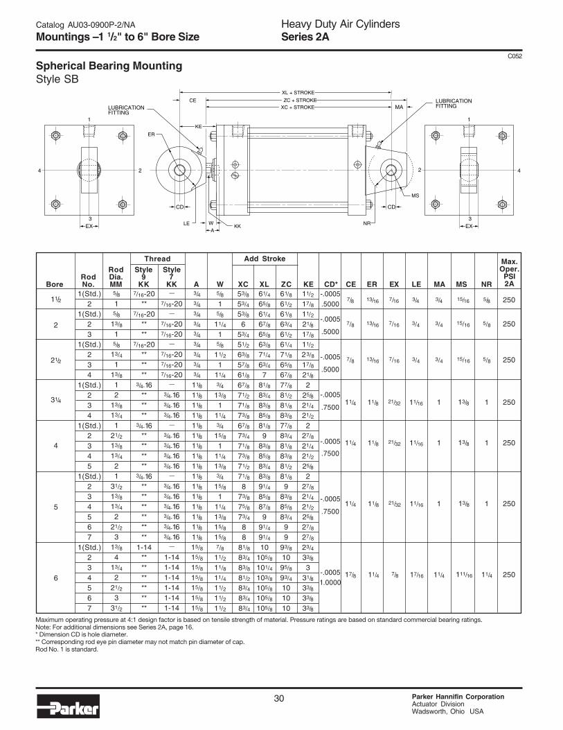
Heavy Duty Air CylindersSeries 2A
Parker Hannifin CorporationActuator DivisionWadsworth, Ohio USA
30
C052
Catalog AU03-0900P-2/NA
Mountings – 1 1/2" to 6" Bore Size
Rod Style StyleRod Dia. 9 7
Bore No. MM KK KK A W XC XL ZC KE CD* CE ER EX LE MA MS NR3/43/43/43/43/43/43/43/43/4
11/8
11/8
11/8
11/8
11/8
11/8
11/8
11/8
11/8
11/8
11/8
11/8
11/8
11/8
11/8
11/8
15/8
15/8
15/8
15/8
15/8
15/8
15/8
61/4
65/8
61/4
67/8
65/8
63/8
71/4
63/4
781/8
83/4
83/8
85/8
81/8
983/8
85/8
83/4
83/8
91/4
85/8
87/8
991/4
91/4
10105/8
101/4
103/8
105/8
105/8
105/8
—
7/16-20—
7/16-207/16-20
—
7/16-207/16-207/16-20
—
3/4-163/4-163/4-16
—
3/4-163/4-163/4-163/4-16
—
3/4-163/4-163/4-163/4-163/4-163/4-16
—
1-141-141-141-141-141-14
61/8
61/2
61/8
63/4
61/2
61/4
71/8
65/8
67/8
77/8
81/2
81/8
83/8
77/8
83/4
81/8
83/8
81/2
81/8
983/8
85/8
83/4
99
93/8
1095/8
93/4
101010
11/2
17/8
11/2
21/8
17/8
11/2
23/8
17/8
21/8
225/8
21/4
21/2
227/8
21/4
21/2
25/8
227/8
21/4
21/2
25/8
27/8
27/8
23/4
33/8
331/8
33/8
33/8
33/8
-.0005.5000
-.0005
.5000
-.0005
.5000
-.0005
.7500
-.0005
.7500
-.0005
.7500
-.00051.0000
7/16-20**
7/16-20****
7/16-20******
3/4-16******
3/4-16********
3/4-16************
1-14************
Thread
11/2
2
21/2
31/4
4
5
6
5/8
15/8
13/8
15/8
13/4
113/8
12
13/8
13/4
121/2
13/8
13/4
21
31/2
13/8
13/4
221/2
313/8
413/4
221/2
331/2
Add Stroke
5/8
15/8
11/4
15/8
11/2
111/43/4
13/8
111/43/4
15/8
111/4
13/83/4
15/8
111/4
13/8
15/8
15/87/8
11/2
11/8
11/4
11/2
11/2
11/2
53/8
53/4
53/8
653/4
51/2
63/8
57/8
61/8
67/8
71/2
71/8
73/8
67/8
73/4
71/8
73/8
71/2
71/8
873/8
75/8
73/4
88
81/8
83/4
83/8
81/2
83/4
83/4
83/4
3/4
3/4
3/4
11/16
11/16
11/16
17/16
13/16
13/16
13/16
11/8
11/8
11/8
11/4
7/16
7/16
7/16
21/32
21/32
21/32
7/8
3/4
3/4
3/4
1
1
1
11/4
7/8
7/8
7/8
11/4
11/4
11/4
17/8
5/8
5/8
5/8
1
1
1
11/4
250
250
250
250
250
250
250
Max.Oper.
PSI2A
1(Std.)2
1(Std.)23
1(Std.)234
1(Std.)234
1(Std.)2345
1(Std.)234567
1(Std.)234567
4
EX
CD
LUBRICATIONFITTING
LUBRICATIONFITTING
3
2
1
CD
MA
A
KE
LE
ER
CE
KKW
ZC + STROKEXC + STROKE
XL + STROKE
NR
MS
4
EX3
2
1
15/16
15/16
15/16
13/8
13/8
13/8
111/16
Maximum operating pressure at 4:1 design factor is based on tensile strength of material. Pressure ratings are based on standard commercial bearing ratings.Note: For additional dimensions see Series 2A, page 16.* Dimension CD is hole diameter.** Corresponding rod eye pin diameter may not match pin diameter of cap.Rod No. 1 is standard.
Spherical Bearing MountingStyle SB
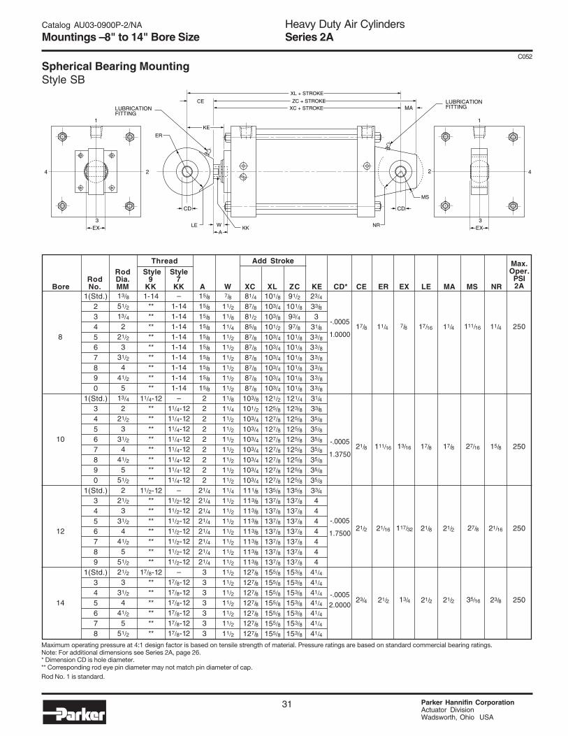
Heavy Duty Air CylindersSeries 2A
31 Parker Hannifin CorporationActuator DivisionWadsworth, Ohio USA
C052
Catalog AU03-0900P-2/NA
Mountings – 8" to 14" Bore Size
Maximum operating pressure at 4:1 design factor is based on tensile strength of material. Pressure ratings are based on standard commercial bearing ratings.Note: For additional dimensions see Series 2A, page 26.* Dimension CD is hole diameter.** Corresponding rod eye pin diameter may not match pin diameter of cap.Rod No. 1 is standard.
11/4
15/8
21/16
23/8
250
250
250
250
-.0005
1.0000
-.0005
1.3750
-.0005
1.7500
-.00052.0000
1(Std.)234567890
1(Std.)34567890
1(Std.)3456789
1(Std.)345678
Rod Style StyleRod Dia. 9 7
Bore No. MM KK KK A W XC XL ZC KE CD* CE ER EX LE MA MS NR15/8
15/8
15/8
15/8
15/8
15/8
15/8
15/8
15/8
15/8
222222222
21/4
21/4
21/4
21/4
21/4
21/4
21/4
21/4
3333333
81/4
87/8
81/2
85/8
87/8
87/8
87/8
87/8
87/8
87/8
103/8
101/2
103/4
103/4
103/4
103/4
103/4
103/4
103/4
111/8
113/8
113/8
113/8
113/8
113/8
113/8
113/8
127/8
127/8
127/8
127/8
127/8
127/8
127/8
101/8
103/4
103/8
101/2
103/4
103/4
103/4
103/4
103/4
103/4
121/2
125/8
127/8
127/8
127/8
127/8
127/8
127/8
127/8
135/8
137/8
137/8
137/8
137/8
137/8
137/8
137/8
155/8
155/8
155/8
155/8
155/8
155/8
155/8
–1-141-141-141-141-141-141-141-141-14
–11/4-1211/4-1211/4-1211/4-1211/4-1211/4-1211/4-1211/4-12
–11/2-1211/2-1211/2-1211/2-1211/2-1211/2-1211/2-12
–17/8-1217/8-1217/8-1217/8-1217/8-1217/8-12
91/2
101/8
93/4
97/8
101/8
101/8
101/8
101/8
101/8
101/8
121/4
123/8
125/8
125/8
125/8
125/8
125/8
125/8
125/8
135/8
137/8
137/8
137/8
137/8
137/8
137/8
137/8
153/8
153/8
153/8
153/8
153/8
153/8
153/8
23/4
33/8
331/8
33/8
33/8
33/8
33/8
33/8
33/8
31/4
33/8
35/8
35/8
35/8
35/8
35/8
35/8
35/8
33/4
4444444
41/4
41/4
41/4
41/4
41/4
41/4
41/4
1-14******************
11/4-12****************
11/2-12**************
17/8-12************
Thread
13/8
51/2
13/4
221/2
331/2
441/2
513/4
221/2
331/2
441/2
551/2
221/2
331/2
441/2
551/2
21/2
331/2
441/2
551/2
8
10
12
14
7/8
11/2
11/8
11/4
11/2
11/2
11/2
11/2
11/2
11/2
11/8
11/4
11/2
11/2
11/2
11/2
11/2
11/2
11/2
11/4
11/2
11/2
11/2
11/2
11/2
11/2
11/2
11/2
11/2
11/2
11/2
11/2
11/2
11/2
Add Stroke
11/4
111/16
21/16
21/2
17/8
21/8
21/2
23/4
111/16
27/16
27/8
35/16
17/16
17/8
21/8
21/2
7/8
13/16
117/32
13/4
11/4
17/8
21/2
21/2
Max.Oper.PSI2A
4
EX
CD
LUBRICATIONFITTING
LUBRICATIONFITTING
3
2
1
CD
MA
A
KE
LE
ER
CE
KKW
ZC + STROKEXC + STROKE
XL + STROKE
NR
MS
4
EX3
2
1
Spherical Bearing MountingStyle SB

Heavy Duty Air CylindersSeries 2A
Parker Hannifin CorporationActuator DivisionWadsworth, Ohio USA
32
C052
Catalog AU03-0900P-2/NA
Double Rod Models – 1" to 14" Bore Size
MountingStyles forSingle Rod
Models
TTB**TDJ
JB**C**EF
CBGD
DD
MountingStyles for
CorrespondingDouble Rod
Models*
KTKTBKTDKJ
KJBKCKEKF
KCBKGKD
KDD†
Dimensions Shown onThis Page SupplementDimensions on Pages
Listed Below1"-6" 8"-14"Bores Bores
Page No. Page No.
6
666
81010
101212
1414
181818
—18, 2019, 22
222426
242828
*If only one end of these Double Rod Cylinders is tobe cushioned, be sure to specify clearly which endthis will be.**Available in 7" bore, page 18.
†Specify XI dimension from rod end #1.
Add Stroke
1
11/2
2
21/2
31/4
4
5
6
7
8
10
12
14
Add 2XStroke
6
61/8
61/8
61/4
71/2
71/2
73/4
83/4
87/8
87/8
103/8
111/8
131/8
—
All Mtgs.
51/2
53/4
513/16
515/16
71/8
71/8
77/16
85/16
—
—
—
—
—
ZB
*
61/2
63/4
7
8
81/8
89/16
93/8
—
9
107/16
111/16
131/8
ZE
*
61/4
67/16
611/16
75/8
73/4
81/16
87/8
—
83/8
913/16
107/16
123/8
XE
G
*
63/8
63/4
71/8
73/4
8
83/8
9
—
77/8
91/4
93/4
115/8
SE
21/8
21/4
21/4
23/8
25/8
25/8
27/8
31/8
31/4
31/4
41/8
45/8
51/2
SN
F
33/8*
33/8
33/8
31/2
33/4
33/4
35/8
41/8
41/4
41/4
47/8
53/8
63/8
SS
C,E
61/2
67/8
67/8
7
81/2
81/2
9
97/8
—
93/4
111/2
121/8
143/8
ZA
63/16
61/2
61/2
65/8
8
8
83/8
91/4
—
91/16
105/8
111/4
135/16
XA
CB
63/8
67/8
67/8
7
81/2
81/2
9
93/4
—
91/4
107/8
113/8
131/2
SA
1
1
1
1
1
1
1
1
1
1
1
1
1
Replaces:On single rod
mounting styles: All Mtg. Styles
* Mounting styles KE, KG, and KDD not available in 1" and 7" bore sizes.
RodRod Dia.
Bore No. MM LD ZL SAK XAK ZAK SSK SNK SEK XEK ZEK ZM1/25/85/85/8
1
1
1
13/8
13/8
13/8
13/4
2
21/2
43/4
47/8
47/8
5
6
6
61/4
7
71/8
71/8
81/8
85/8
101/8
LB
All dimensions are in inches and apply to Code 1 rod sizes only. For alternate rod sizes, determineall envelope dimensions (within LD dim.) as described above and then use appropriate rod enddimensions for proper rod size from single rod cylinder.
To determine dimensions for a double rodcylinder, first refer to the desired single rodmounting style cylinder shown on precedingpages of this catalog. (See table at left.) Afterselecting necessary dimensions from thatdrawing, return to this page and supplementthe single rod dimensions with those shown ondrawings above and dimension table below.Note that double rod cylinders have a head(Dim. G) at both ends and that dimension LDreplaces LB and ZL replaces ZB, etc. The
double rod dimensions differ from, or are inaddition to those for single rod cylindersshown on preceding pages and provide theinformation needed to completely dimensiona double rod cylinder.On a double rod cylinder where the two rodends are different, be sure to clearly statewhich rod end is to be assembled at whichend. Port position 1 is standard. If other thanstandard, specify pos. 2, 3, or 4 when viewedfrom rod end #1 only.
How to Use Double Rod Cylinder Dimensioned Drawings
F
P + STROKELD + STROKE
ZM + 2 X STROKE
WEE
Y
K
MM
G F
GWF
GFK
G F
P + STROKELD + STROKE
ZM + 2 X STROKE
ZL + STROKE
W
EE
Y
MM
1"- 6" Bores
7"- 14" Bores
Rod End #1 Rod End #2
Rod End #1 Rod End #2

Heavy Duty Air CylindersSeries 2A
33 Parker Hannifin CorporationActuator DivisionWadsworth, Ohio USA
C052
Catalog AU03-0900P-2/NA
Cylinder Accessories / Spherical Bearing
CL
CD
Spherical Rod Eye
Order to fit Piston Rod Thread Size.
Bore Sizes Series 2A 11/2, 2 & 21/2 31/4, 4 & 5 6 & 8 10 12 14
Part No. 83947 83948 83949 83950 83951 83952
CD
CF
CW
DD
E
F
FL
LR
M
MR
R
LOADCAPACITY
LBS.
1/27/16
1/213/32
31/2
11/215/16
1/25/8
2.05
3/421/32
5/817/32
33/45/8
213/87/8
12.76
17/83/4
17/32
51/23/4
21/2
111/16
113/16
4.10
13/8
13/16
121/32
61/27/8
31/2
27/16
13/8
15/8
4.95
13/4
117/32
11/429/32
81/2
11/4
41/2
27/8
13/4
21/16
6.58
213/4
11/229/32
105/8
11/2
535/16
223/8
7.92
9450 14300 20322 37800 503755770
CD
CL
LOADCAPACITY
LBS.
Bore Sizes Series 2A 11/2, 2 & 21/2 31/4, 4 & 5 6 & 8 10 12 14
Pivot Pin Part No. 83962 83963 83964 83965 83966 83967
.4997-0004
19/16
.7497-0005
21/32
.9997-0005
21/2
1.3746-0006
35/16
1.7496-0006
47/32
1.9996-0007
415/16
19300 34300 65000 105200 1374008600
Bore Sizes Series 2A 11/2, 2 & 21/2 31/4, 4 & 5 6 & 8 10 12 14
Rod Eye Part No. 132290 132291 132292 132293 132294 132295
.5000-0005
11/16
7/87/16
13/16
3/47/16-20
7/8
.7500-0005
111/421/32
11/8
11/16
3/4-1615/16
1.0000-0005
11/2
17/87/8
11/4
17/16
1-1411/2
1.3750-0005
221/8
13/16
111/16
17/8
11/4-122
1.7500-0005
21/8
21/2
117/32
21/16
21/8
11/2-1221/4
2.0000-0005
27/8
23/4
13/4
21/2
21/2
17/8-1223/4
CD
A
CE
EX
ER
LE
JK
JL
LOADCAPACITY
LBS.2644 9441 16860 28562 43005 70193
Parker offers a complete range of Cylinder Accessoriesto assure you of the greatest versatility in present orfuture cylinder applications. Accessories offered for the
respective cylinder include the Rod Eye, Pivot Pin andClevis Bracket. To select the proper part number (for anydesired accessory) refer to the charts below.
Clevis Bracket
LE
CD
JKTHD
ER (MAX)
LUBEFITTING
CE
A
EX
JL DIA
Pivot Pin
Pivot Pins are furnished with(2) Retainer Rings.
Clevis Bracket
Order to fit Mounting Plate or Rod Eye.
MR
LR
RE
DD DIA4 HOLES
F
M
FL
CW CWCF
+ .004+ .002
RE
CD

Heavy Duty Air CylindersSeries 2A
Parker Hannifin CorporationActuator DivisionWadsworth, Ohio USA
34
C052
Catalog AU03-0900P-2/NA
Cylinder Accessories
25˚MR
LR
RE
DD DIA4 HOLES
F
M
FL
CW CWCB
+ .004+ .002
RE
CD
†For alignment coupler dimensions, see Section H of this catalog.*Cylinder accessory dimensions conform to NFPA recommended standard NFPA/T3.6.8 R1-1984, NFPA recommendedstandard fluid power systems — cylinder — dimensions for accessories for cataloged square head industrial types. Parkeradopted this standard in April, 1985. Eye Brackets or Mounting Plates shipped before this date may have differentdimensions and will not necessarily interchange with the NFPA standard. For dimensional information on older style EyeBrackets or Mounting Plates consult Drawing #144805 or consult the Cylinder Division.NOTE: For economical accessory selection, it is recommended that rod end style 4 be specified on your cylinder order.
Cylinder AccessoriesParker offers a complete range of cylinder accessories to assureversatility in present or future cylinder applications.
Rod End AccessoriesAccessories offered for the rod end of the cylinder include Rod Clevis,Eye Bracket, Knuckle, Clevis Bracket and Pivot Pin. To select the properpart number for any desired accessory, refer to Chart A below and lookopposite the thread size of the rod end as indicated in the first column.The Pivot Pins, Eye Brackets and Clevis Brackets are listed opposite thethread size which their mating Knuckles or Clevises fit.
Chart ACB
CDER +.004+.002
CD CA
CD
CDKK THREAD
A FULLTHREAD
CBCW CWER
KK THREAD
+.004+.002CD
A
CE
➁ Female Rod Clevis
Order to fit thread size.
➂ Knuckle (Female Rod Eye)
Order to fit thread size.
➃ Clevis Bracket for Knuckle
Order to fit Knuckle.
➇ Mounting Plate or ➄ Eye Bracket
1. When used to mate with the Rod Clevis, select from Chart A.2. When used to mount the Style BB or BC cylinders, select from the
Mounting Plate Selection Table. See Chart B at lower left.
➅ Pivot Pin
1. Pivot Pins are furnished with Clevis Mounted Cylinders asstandard.
2. Pivot Pins are furnished with (2) Retainer Rings.3. Pivot Pins must be ordered as a separate item if to be used with
Knuckles, Rod Clevises, or Clevis Brackets.
➧
➧
➧
➧
➧
MR
LR
RE
DD DIA4 HOLES
F
M 25˚
FL
CB
+ .004+ .002
RE
CD
➇
➃
➄
➅➁
➂
Accessory Load CapacityThe various accessories on Pages 34 and 35have been load rated for your convenience. Theload capacity in lbs. shown on page 35, is therecommended maximum load for that accessorybased on a 4:1 design factor in tensions. (PivotPin is rated in shear.) Before specifying, comparethe actual load or the tension (pull) force atmaximum operating pressure of the cylinder withthe load capacity of the accessory you plan to use.If load or pull force of cylinder exceeds loadcapacity of accessory, consult factory.
Mating PartsMating Parts
5/16-247/16-201/2-203/4-163/4-167/8-141-141-14
11/4-1211/4-1211/2-1213/4-1217/8-1221/4-1221/2-1223/4-1231/4-1231/2-124-12
41/2-12
51221509405094150942
1332845094350944
13328550945
133286509465094750948509495095050951509525095350954
–
7407769195691956919669196*85361*85361*853616919869198*85362*85363*85363*85364*85365*85365735387353973539
–
—683686836868369683696837068370683706837168371683726837368373683746837568375735457354773547
–
7407569089690906909169091690926909369093690946909469095690966909769098690996910073536734377343873439
74076692056920569206†
69206692076920769207692086920869209692106921069211692126921373542735427354373544
7407868368683686836968369683706837068370683716837168372692156921568374683756921673545735458218173547
134757 0031134757 0044134757 0050134757 0075134757 0075134757 0088134757 0100134757 0100134757 0125134757 0125133739 0150133739 0175133739 0188
ConsultFactory
Thread Rod Eye Clevis Alignment Size Clevis Bracket Pin Knuckle Bracket Pin Coupler
Mtg. PlatePart No.
74076‡
69195
69196
*85361
69198
*85362
*85363
Series 2ABore Size
1"
11/2", 2", 21/2"
31/4", 4", 5"
6", 7", 8"10"
12"14"
Chart B
‡Mounting plate for 1" bore single lugBC & BB cylinder mounting style isClevis Bracket P/N 74076.
CL
CD+.001 -.002
Mounting PlatesMounting Plates for Style BB and Style BC(Clevis mounted) cylinders are offered. To selectproper part number for your application, refer to Chart B, above right.

Heavy Duty Air CylindersSeries 2A
35 Parker Hannifin CorporationActuator DivisionWadsworth, Ohio USA
C052
Catalog AU03-0900P-2/NA
Cylinder Accessories
509534‡
41/24
813/16
21/44
31/2-12
193200
5095131/233
63/411/223/4
23/4-12
98200
509544‡
41/24
813/16
21/44
4-12
221200
5095231/2‡
431/273/42
31/231/4-12
156700
Clevis Bracket for Knuckle Part Number
Eye Bracket and Mounting Plate Part Number
ACBCDCECWERKK
Load Capacity Lbs. O
CBCDCWDDEF
FLLRM
MRR
Load Capacity Lbs.O
51221†
13/16
11/32
5/16
21/413/64
19/64
5/16-24
2600
509403/43/41/2
11/21/21/2
7/16-20
4250
509413/43/41/2
11/21/21/2
1/2-20
4900
13328411/811/43/4
23/85/83/4
3/4-16
11200
5094315/811/21
215/16
3/41
7/8-14
18800
5094415/811/21
215/16
3/41
1-14
19500
5094211/811/43/4
21/85/83/4
3/4-16
11200
13328515/811/21
31/83/41
1-14
19500
13328622
13/841/81
13/811/4-12
33500
5094621/421/213/441/211/413/4
11/2-12
45600
5094931/23
21/261/211/221/2
21/4-12
98200
5095031/233
63/411/223/4
21/2-12
98200
5094517/82
13/833/41
13/811/4-12
33500
509473
21/22
51/211/42
13/4-12
65600
509483
21/22
51/211/42
17/8-12
65600
7407615/32
7/16
3/817/64
21/43/81
5/83/81/2
1.75
3600
692053/41/21/2
13/32
31/21/2
11/23/41/25/8
2.55
7300
6920611/43/45/8
17/32
55/817/813/16
3/429/32
3.82
14000
6920711/21
3/421/32
61/23/4
21/411/21
11/44.95
19200
692082
13/81
21/32
71/27/832
13/8121/32
5.73
36900
6920921/213/411/429/32
91/27/8
35/823/413/427/32
7.50
34000
692113
21/211/213/16
123/41
41/231/221/231/89.40
34900
6921021/22
11/211/16
123/41
41/433/16
21/4225/32
9.40
33000
6921233
11/215/16
123/416
41/43
319/32
9.40
33800
6921331/23
11/215/16
123/416
41/43
319/32
9.40
36900
735424
31/22
113/16
151/2111/16
611/16
531/241/8
12.00
83500
7354341/242
21/16
171/2115/16
711/16
53/44
47/813.75
102600
73544542
21/16
171/2115/16
711/16
53/44
47/813.75
108400
740775/16
5/16
17/64
21/43/81
5/83/81/2
1.75
1700
691953/41/2
13/32
21/23/8
11/83/41/29/16
1.63
4100
85363*21/22
11/16
71/211/24
21/22
27/16
5.73
70000
CBCDDDEF
FLLRM
MRR
Load Capacity Lbs.O
6919611/43/4
17/32
31/25/8
17/811/43/47/8
2.55
10500
85361*11/21
21/32
41/27/8
23/811/21
11/43.25
20400
691982
13/821/32
57/83
21/813/815/83.82
21200
85362*21/213/429/32
61/211/833/821/413/421/84.95
49480
Pivot Pin Part Number
CDCL
Shear Capacity Lbs.O
85364*3
21/213/16
81/213/443/43
21/23
6.58
94200
Knuckle Part Number74075
3/411/27/16
7/16
19/32
5/16-24
3300
690893/4
11/23/41/2
23/32
7/16-20
5000
7343951/291/854
511/16
41/2-12
308500
7343851/291/841/24
511/16
4-12
273800
734375
75/84
31/2431/32
31/2-12
217300
7353641/275/84
31/2431/32
31/4-12
161300
6910035/861/231/23
41/423/4-12
123300
6909931/261/833
41/421/2-12
110000
6909831/2
513/16
321/239/16
21/4-12
98700
6909735
21/22
227/32
17/8-12
75000
6909621/443/821/22
227/32
13/4-12
53500
6909521/44
21/213/421/2
11/2-12
45000
690942
37/16
213/8
131/32
11/4-12
33500
6909315/8
213/16
11/21
17/16
1-14
21700
6909211/823/811/21
17/16
7/8-14
13000
6909111/821/16
11/43/4
11/16
3/4-16
12100
690903/411/23/41/2
23/32
1/2-20
5700
ACACBCDERKK
Load Capacity Lbs.O
85365*33
15/16
91/22
51/431/423/431/47.50
121900
735384
31/2113/16
125/8111/16
511/16
431/241/89.62
57400
7353941/24
21/16
147/8115/16
67/16
41/24
51/411.45
75000
740787/16
15/16
6600
683681/2
17/8
8600
683693/4
25/8
19300
683701
31/8
34300
6837113/841/8
65000
6837213/453/16
105200
683732
53/16
137400
692152
511/16
137400
6837421/263/16
214700
683753
61/4
309200
692163
63/4
309200
7354531/281/4
420900
73547•
49
565800
821814
85/8
565800
Female Rod Clevis Part Number
*Cylinder accessory dimensions conform to NFPA recommended standard NFPA/T3.6.8 R1-1984, NFPA recommended standard fluid power systems — cylinder —dimensions for accessories for cataloged square head industrial types. Parker adopted this standard in April, 1985. Eye Brackets or Mounting Plates shipped before thisdate may have different dimensions and will not necessarily interchange with the NFPA standard. For dimensional information on older style Eye Brackets or Mounting Platesconsult Drawing #144805.O See Accessory Load Capacity note on page 34.•These sizes supplied with cotter pins.†Includes Pivot Pin.‡Consult appropriate cylinder rod end dimensions for compatibility.

Heavy Duty Air CylindersSeries 2A
Parker Hannifin CorporationActuator DivisionWadsworth, Ohio USA
36
C052
Catalog AU03-0900P-2/NA
How To Order
How to Order Series “2A” CylindersWhen ordering Series 2A cylinders, please review the following:Note: Duplicate cylinders can be ordered by giving the SERIALNUMBER from the nameplate of the original cylinder. Factory recordssupply a quick positive identification.
Piston Rods: Specify rod code number based on diameter. Givethread style number for a standard thread or specify dimensions. See“Style 3 Rod End” below.
Cushions: If cushions are required, specify according to the modelnumber on the next page. If the cylinder is to have a double rod andonly one cushion is required, be sure to specify clearly which end ofthe cylnder is to be cushioned.
Service PolicyOn cylinders returned to the factory for repairs, it is standard policy forthe Cylinder Division to make such part replacements as will put thecylinder in as good as new condition. Should the condition of the returnedcylinder be such that expenses for repair would exceed the costs of anew one, you will be notified.Address all correspondence and make shipments to, ServiceDepartment at your nearest regional plant listed in the pages of thiscatalog.
Certified DimensionsParker Cylinder Division guarantees that all cylinders ordered from thiscatalog will be built to dimensions shown. All dimensions are certified tobe correct, and thus it is not necessary to request certified drawings.
Class 1 SealsClass 1 seals are the seals provided as standard in a cylinderassembly unless otherwise specified. For further information on fluidcompatibility or operating limitations of all components, see section C.For the Series 2A cylinders the following make-up Class 1 Seals:
Primary Piston Rod Seal – Nitrile with PTFE back-up washers
Piston Rod Wiper – NitrilePiston Seals – Nitrile with polymyte back-up washersO-Rings – Nitrile
Style 3 Rod EndA style 3 rod end indicates a special rod end configuration. All specialpiston rod dimensions must have all three: KK; A; W/WF or LA/LAFspecified with the rod fully retracted. A sketch or drawing should besubmitted for rod ends requiring special machining such as snap ringgrooves, keyways, tapers, multiple diameters, etc. It is good designpractice to have this machining done on a diameter at least 0.065inches smaller than the piston rod diameter. This allows the piston rodto have a chamfer preventing rod seal damage during assembly or
maintenance. Standard style 55 rod ends with a longer than standardWG dimension should call out a style 3 rod end and the note: sameas 55 except WG=____. A drawing should be submitted for special55 rod ends that have specific tolerances or special radii. Special rodends that have smaller than standard male threads, larger thanstandard female threads, or style 55 rod ends with smaller thanstandard AF or AE dimensions are to be reviewed by Engineering forproper strength at operating pressure.
Combination MountingsSingle Rod End The first mounting is the one called out on the headend of the cylinder. The second (or subsequent mountings) are calledout as they appear in the assembly, moving away from the rod end.Exception: When tie rod mountings are part of a combination, themodel number should contain an “S” (Special) in the model code anda note in the body of the order clarifying the mounting arrangement.The ”P” is used to define a thrust key and is not considered to be amounting. However, it is located at the primary end.Example: 4.00 CCBB2ALTS14AC x 10.000Combination “C” mounting head only. “BB” mounting cap endThis cylinder is also cushioned at both ends.
Double Rod End In general, the model number is read left to rightcorresponding to the cylinder as viewed from left to right with the
primary end at rod end #1. (See Double Rod Models information pagein this section.) For this option the piston rod number, piston rod end,and piston rod threads are to be specified for both ends. The simplestare for symmetric cylinders such as: TD, C, E, F, G, and CB mounts.All other mounting styless, the description of the first rod end will be atthe mounting end. In the case of multiple mounts, the description ofthe first rod end will be at the primary mounting end. For “DD”mounts, the description of the first rod end will be the same locationas the “XI” dimension.
Example: 4.00 KDD2ALT24A/18A x 10.000 XI=8This is a center trunnion mounting cylinder with the XI dimensionmeasured from the code 2 rod side of the cylinder which has the style4 thread. The opposite end code 1 rod with the style 8 thread.
Special Modifications: Additional information is required on ordersfor cylinders with special modifications. This is best handled withdescriptive notes. For further information, consult factory.
Fluid Medium: Series 2A hydraulic cylinders are equipped with sealsfor use with lubricated air.

Heavy Duty Air CylindersSeries 2A
37 Parker Hannifin CorporationActuator DivisionWadsworth, Ohio USA
C052
Catalog AU03-0900P-2/NA
Model Numbers
Series 2A Model Numbers – How to Develop Them – How to “Decode” ThemParker Series 2A cylinders can be completely and accurately describedby a model number consisting of coded symbols. To develop a model
number, select only those symbols that represent the cylinder required,and place them in the sequence indicated below.
*Required for Basic Cylinder Model Number Cylinder serial numbers are factory production recordnumbers and are assigned to each cylinder in additionto the model number.Note: For sensor specifications and part numbers,please see the electronic sensor section.
‡ Specify XI dimension †† In case of Stop Tube, call out gross
stroke length (net stroke + stop tubelength).
!! For information regarding Style 55 RodEnds, please refer to page 43, Section Cof this catalog.
BoreSize*
6" C K
CushionHead End
MountingStyle*
DoubleRod
P
MountingModifications
TB
CombinationMounting
Style
2A
Series*
T
Ports*
V
CommonModifications
S
SpecialModifications
1
Piston RodNumber*
4
Piston RodEnd*
F 2
Piston RodAlternateThread
A
Piston RodThreads*
C
CushionCap End
12"
Stroke*††
Specifyin inches.
Used onlyif cushionhead end isrequired.
Used onlyif double rodcylinder isrequired.
Specify MountingStyle TB, TC, TD,J, H, JB, HB, C, E,F, CB, G, BB, D,DB, DD‡, BC, SB.
P = Thrust Key(Styles C, F, G& CB only)M = ManifoldPort O-RingSeal (Style Conly)R = RemovableTrunnions
Any practicalmounting styleas listed under“Mounting Style”.
Used inall 2AModelNumbers.
U = NPTF (Dry Seal Pipe Thread)(standard). Used only forSAE Straight Thread.
T = O-Ring PortR = Used only for BSP
(Parallel Thread ISO 228)B = Used only for BSPT
(Taper Thread ISO 7-Rc)G = Used only for Metric ThreadY = Used only for Metric Thread
per ISO 6149
Used only if specialmodifications arerequired.Do not use “S” for rodend modifications.
For single rodcylinders,select one only.Note: Checkrod selectionchart inEngineeringSection forappropriatepiston roddiameter.
Specifyin inches.
Used onlyif cushioncap end isrequired.
A = UNFStandard
W = BSF(British Fine)
M = Metric
Used onlyfor stud twotimes longerthan standard.
F = NutRetainedPiston
V = Fluoro-carbonSeals
W = WaterService
Select:Style 4 Small MaleStyle 7 Female Thread for
Spherical Rod EyeStyle 8 Intermediate MaleStyle 9 Short FemaleStyle 55 Rod End for Flange Coupling !!Style 3 Special (Specify)
Double Rod Cylinders
For double rod cylinders,specify rod number and rodend symbols for both pistonrods. A typical double rodmodel number would be:
6" KJ-2AU14A/14AX12"

Heavy Duty Air CylindersSeries 2A
Parker Hannifin CorporationActuator DivisionWadsworth, Ohio USA
38
Catalog AU03-0900P-2/NA
Notes
NOTES
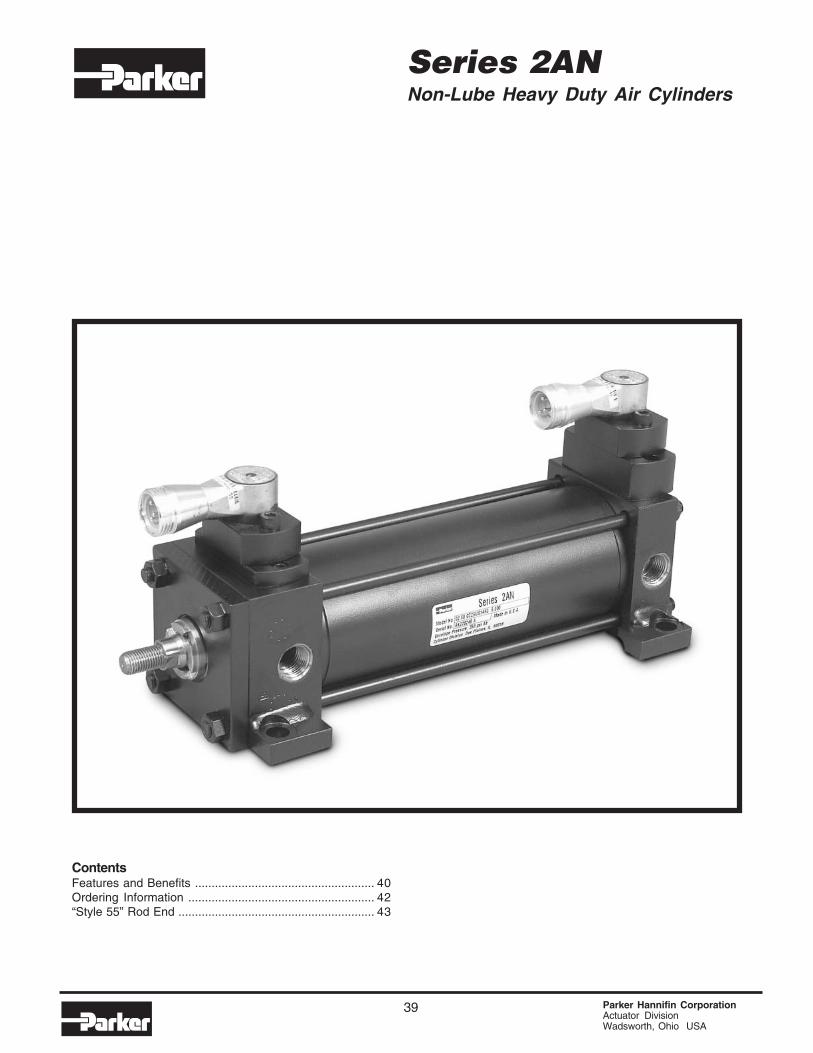
39 Parker Hannifin CorporationActuator DivisionWadsworth, Ohio USA
Series 2ANNon-Lube Heavy Duty Air Cylinders
ContentsFeatures and Benefits ...................................................... 40Ordering Information ........................................................ 42“Style 55” Rod End ........................................................... 43

Parker Hannifin CorporationActuator DivisionWadsworth, Ohio USA
40
the Series 2AN Non-Lubricated Air Cylinder. In boresizes to 12" diameter and rod diameters to 2-1/2", theParker Series 2AN air cylinder features rounded lip rodand piston seals. These seals glide over the PTFEbased lubricant that is provided at the time ofmanufacture. The Parker Series 2AN Non LubricatedAir Cylinder maintains the lubricant film where itbelongs; on the seals bearing surfaces, piston rodand cylinder bore.
Benefits include… long seal and bearing life. No oilneeds to be added through the use of lubricators.As the cylinder strokes, no oil is expelled into theatmosphere with the exhaust air.
Design DataIn 1971, Parker experimented with the use of speciallydesigned composite materials in the piston and glandof their cylinders. Their use of storing lubricating oil metwith good results. Through extensive testing it waslearned that the outside diameter of the material in thepiston, and the inside diameter on the material in thegland showed signs of wear and ultimately would losecontact with the surface of the cylinder body bore orpiston rod. As a result, the cylinders lost their selflubricating capacity.
Today's industrial market demands more from apneumatic cylinder. Cylinders are still required tohandle tough, heavy-duty applications. Frequently,these cylinders operate in environments or circum-stances where it is not possible (or advantageous)to add lubrication to the compressed air entering thecylinder. Certain packaging and assembly operations,food environments, and microprocessor chip manu-facturing are typical examples of areas where theexhausting of oil into the environment is not desirable.In many other situations, “non-lube” systems are usedwhen proper air line lubrication is not present becauseof the time and expense of keeping lubricators filledand operating correctly.
Increased market demand and continuous researchand development efforts inspired the development of
High integrity lubricant film with suspended PTFE particles
Increased heel thicknessand outer lip extensionimprove stability, resistrolling.
Another Parker Cylinder Innovation…The Series 2AN Non-Lube Air Cylinderwith Proven Performance.
Piston Lipseals
Gland Lipseals
Rounded sealing lip glides overlubricant film instead of scrapingit off. Reduces friction, increaseslife and eliminates the need foradded lubrication.
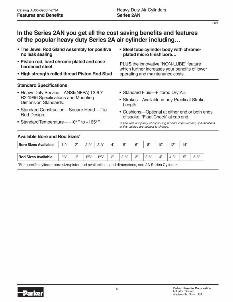
Heavy Duty Air CylindersSeries 2AN
41 Parker Hannifin CorporationActuator DivisionWadsworth, Ohio USA
C052
Catalog AU03-0900P-2/NA
Features and Benefits
Available Bore and Rod Sizes*
*For specific cylinder bore size/piston rod availabilities and dimensions, see 2A Series Cylinder.
Bore Sizes Available 11/2" 2" 21/2" 31/4" 4" 5" 6" 8" 10" 12" 14"
Rod Sizes Available 5/8" 1" 13/8" 13/4" 2" 21/2" 3" 31/2" 4" 41/2" 5" 51/2"
In the Series 2AN you get all the cost saving benefits and featuresof the popular heavy duty Series 2A air cylinder including…
• The Jewel Rod Gland Assembly for positiveno leak sealing
• Piston rod, hard chrome plated and casehardened steel
• High strength rolled thread Piston Rod Stud
• Steel tube cylinder body with chrome-plated micro finish bore…
PLUS the innovative “NON-LUBE” featurewhich further increases your benefits of loweroperating and maintenance costs.
Standard Specifications
• Heavy Duty Service—ANSI/(NFPA) T3.6.7R2-1996 Specifications and MountingDimension Standards.
• Standard Construction—Square Head —TieRod Design.
• Standard Temperature— -10°F. to +165°F.
• Standard Fluid—Filtered Dry Air.
• Strokes—Available in any Practical StrokeLength.
• Cushions—Optional at either end or both endsof stroke. “Float Check” at cap end.
In line with our policy of continuing product improvement, specificationsin this catalog are subject to change.
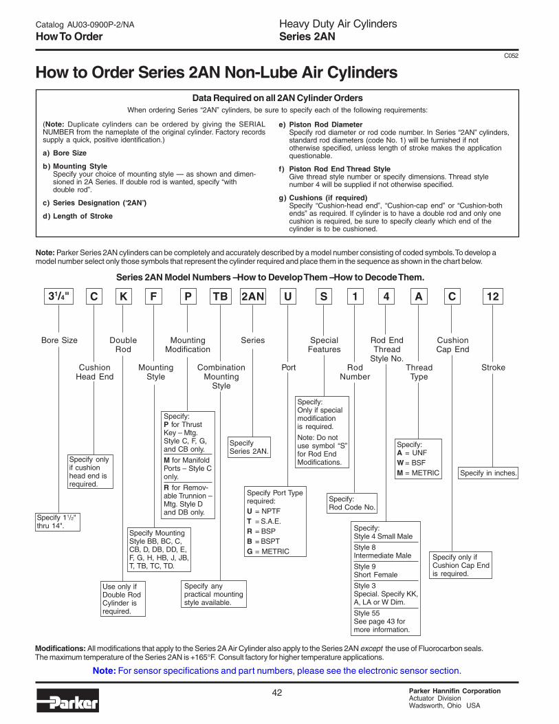
Heavy Duty Air CylindersSeries 2AN
Parker Hannifin CorporationActuator DivisionWadsworth, Ohio USA
42
C052
Catalog AU03-0900P-2/NA
How To Order
How to Order Series 2AN Non-Lube Air CylindersData Required on all 2AN Cylinder Orders
When ordering Series “2AN” cylinders, be sure to specify each of the following requirements:
(Note: Duplicate cylinders can be ordered by giving the SERIALNUMBER from the nameplate of the original cylinder. Factory recordssupply a quick, positive identification.)
a) Bore Size
b) Mounting StyleSpecify your choice of mounting style — as shown and dimen-sioned in 2A Series. If double rod is wanted, specify “withdouble rod”.
c) Series Designation (“2AN”)
d) Length of Stroke
e) Piston Rod DiameterSpecify rod diameter or rod code number. In Series “2AN” cylinders,standard rod diameters (code No. 1) will be furnished if nototherwise specified, unless length of stroke makes the applicationquestionable.
f) Piston Rod End Thread StyleGive thread style number or specify dimensions. Thread stylenumber 4 will be supplied if not otherwise specified.
g) Cushions (if required)Specify “Cushion-head end”, “Cushion-cap end” or “Cushion-bothends” as required. If cylinder is to have a double rod and only onecushion is required, be sure to specify clearly which end of thecylinder is to be cushioned.
Series 2AN Model Numbers – How to Develop Them – How to Decode Them.
Note: Parker Series 2AN cylinders can be completely and accurately described by a model number consisting of coded symbols. To develop amodel number select only those symbols that represent the cylinder required and place them in the sequence as shown in the chart below.
Modifications: All modifications that apply to the Series 2A Air Cylinder also apply to the Series 2AN except the use of Fluorocarbon seals.The maximum temperature of the Series 2AN is +165°F. Consult factory for higher temperature applications.
Bore Size
31/4" C K
CushionHead End
MountingStyle
DoubleRod
P
MountingModification
TB
CombinationMounting
Style
2AN
Series
U
Port
S
SpecialFeatures
1
RodNumber
4
Rod EndThread
Style No.
A
ThreadType
Stroke
F 12C
CushionCap End
Specify 11/2"thru 14".
Specify onlyif cushionhead end isrequired.
Use only ifDouble RodCylinder isrequired.
Specify MountingStyle BB, BC, C,CB, D, DB, DD, E,F, G, H, HB, J, JB,T, TB, TC, TD.
Specify:P for ThrustKey – Mtg.Style C, F, G,and CB only.
M for ManifoldPorts – Style Conly.
R for Remov-able Trunnion –Mtg. Style Dand DB only.
Specify anypractical mountingstyle available.
SpecifySeries 2AN.
Specify Port Typerequired:U = NPTFT = S.A.E.R = BSPB = BSPTG = METRIC
Specify:Only if specialmodificationis required.
Note: Do notuse symbol “S”for Rod EndModifications.
Specify:Rod Code No.
Specify:Style 4 Small Male
Style 8Intermediate Male
Style 9Short Female
Style 3Special. Specify KK,A, LA or W Dim.
Style 55See page 43 formore information.
Specify:A = UNFW = BSFM = METRIC
Specify only ifCushion Cap Endis required.
Specify in inches.
Note: For sensor specifications and part numbers, please see the electronic sensor section.
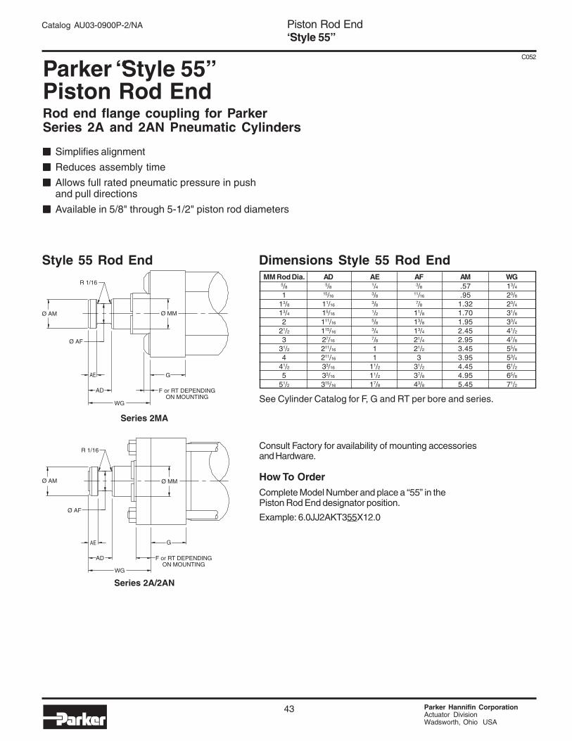
Piston Rod End“Style 55”
43 Parker Hannifin CorporationActuator DivisionWadsworth, Ohio USA
C052
Catalog AU03-0900P-2/NA
Parker “Style 55”Piston Rod EndRod end flange coupling for ParkerSeries 2A and 2AN Pneumatic Cylinders
■■■■■ Simplifies alignment
■■■■■ Reduces assembly time
■■■■■ Allows full rated pneumatic pressure in pushand pull directions
■■■■■ Available in 5/8" through 5-1/2" piston rod diameters
Consult Factory for availability of mounting accessoriesand Hardware.
How To OrderComplete Model Number and place a “55” in thePiston Rod End designator position.
Example: 6.0JJ2AKT355X12.0
Style 55 Rod End Dimensions Style 55 Rod EndMM Rod Dia. AD AE AF AM WG
5/8 5/8 1/4 3/8 .57 13/41 15/16 3/8 11/16 .95 23/8
13/8 11/163/8 7/8 1.32 23/4
13/4 15/16 1/2 11/8 1.70 31/82 111/16
5/8 13/8 1.95 33/421/2 115/16
3/4 13/4 2.45 41/23 27/16 7/8 21/4 2.95 47/8
31/2 211/16 1 21/2 3.45 55/84 211/16 1 3 3.95 53/4
41/2 33/16 11/2 31/2 4.45 61/25 33/16 11/2 37/8 4.95 65/8
51/2 315/16 17/8 43/8 5.45 71/2
See Cylinder Catalog for F, G and RT per bore and series.
R 1/16
Ø AM
Ø AF
Ø MM
AE
AD
WG
G
F or RT DEPENDINGON MOUNTING
F or RT DEPENDINGON MOUNTING
Ø MM
G
R 1/16
Ø AM
Ø AF
AE
AD
WG
Series 2MA
Series 2A/2AN

Piston Rod End“Style 55”
Parker Hannifin CorporationActuator DivisionWadsworth, Ohio USA
44
Catalog AU03-0900P-2/NA
SPLIT WELDROD BOLT COUPLER PLATEDIA. A B C D E F BOLT SIZE CIRCLE PART NO. PART NO.
.625 1.50 2.00 .50 .56 .250 4 #10-24 x .94 LG 1.125 147234 0062 148174 00621.00 2.00 2.50 .50 .88 .250 6 .250-20 x 1.25 LG 1.500 147234 0100 148174 0100
1.375 2.50 3.00 .63 1.00 .250 6 .312-18 x 1.50 LG 2.000 147234 0138 148174 01381.75 3.00 4.00 .63 1.25 .250 8 .312-18 x 1.75 LG 2.375 147234 0175 148174 01752.00 3.50 4.00 .75 1.63 .375 12 .375-16 x 2.25 LG 2.687 147234 0200 148174 02002.50 4.00 4.50 .75 1.88 .375 12 .375-16 x 2.50 LG 3.187 147234 0250 148174 02503.00 5.00 5.50 1.00 2.38 .375 12 .500-13 x 3.25 LG 4.000 147234 0300 148174 03003.50 5.88 7.00 1.00 2.63 .375 12 .625-11 x 3.50 LG 4.687 147234 0350 148174 03504.00 6.38 7.00 1.00 2.63 .375 12 .625-11 x 3.50 LG 5.187 147234 0400 148174 04004.50 6.88 8.00 1.00 3.13 .375 12 .625-11 x 4.00 LG 5.687 147234 0450 148174 04505.00 7.38 8.00 1.00 3.13 .375 12 .625-11 x 4.00 LG 6.187 147234 0500 148174 05005.50 8.25 9.00 1.25 3.88 .375 12 .750-10 x 5.00 LG 6.875 147234 0550 148174 0550
Table 1 — Part Numbers and Dimensions
Note: Screws are not included with split coupler or weld plate.
Parker “Style 55” Piston Rod EndSplit Couplers and Weld Plates
WARNING: Piston rod separation from the machine membercan result in severe personal injury or even death to nearby per-sonnel. The cylinder user must make sure the weld holding theweld plate to the machine is of sufficient quality and size to hold theintended load. The cylinder user must also make sure the boltsholding split coupler to the weld plate are of sufficient strength tohold the intended load and installed in such a way that they will notbecome loose during the machine’s operation.
!
Ø E
C D
F BOLTS
Ø A
Ø B
STYLE 55 ROD END
SPLIT COUPLER
WELD PLATE