series 45 open circuit axial piston pumps technical ... · series 45 open circuit axial piston...
TRANSCRIPT

Displacement Piston
Cylinder Block Kit
Tapered RollerBearing
Valve Plate
Piston
Shaft Seal
Swashplate
Tapered RollerBearing
Series 45Open Circuit Axial Piston Pumps
TechnicalInformation

2BLN-10128 • Revision B • June 2001
Series 45 Axial Piston Open Circuit PumpsTechnical InformationGeneral Description
Series 45 open circuit pumps can be applied with other products in a system to transfer and control hydraulic power.
Series 45 pumps provide an infi nitely variable fl ow rate between zero and maximum.
Series 45 variable displacement pumps are compact, high power density units, using the axial piston concept in conjunction with a tiltable swashplate to vary the pump displacement.
Series 45 pumps use a cradle swashplate design. A hydraulic control piston sets the swashplate angle. Control of the displacement piston is provided through a built-in pressure compensator valve. This valve will vary the swashplate angle from its maximum to its minimum position when the set pressure is reached. Controls are also available for remote compensating and load sensing systems. An available displacement limiter (frame G and H units only) allows adjustment of maximum fl ow to match system requirements. The Series 45 pump controls are designed for low hysteresis and responsive performance.
Copyright 1995, 1999, 2001 Sauer-Danfoss CompanyAll rights reserved. Contents subject to change.Printed in U.S.A. 0601 H
SERIES 45 PRODUCT RANGE
BASIC DESIGN
310[4495]
260[3770]
210[3045]
20 30 40 50 60 70 80 90 100
G74B
H75D
H57B
L25C
L30D
K38C
K45D
G90C
Displacementcc/rev
Co
nti
nu
ou
s P
ress
ure
Rat
ing
bar
[psi
]
P101 575E
Series 45 open circuit pumps cover a displacement range from 25cc [1.53 in3] to 90cc [5.49in3] and a continuous pressure rating range from 210 bar [3045 psi] to 310 bar [4495 psi] with peak pressure ratings to 400 bar [5800 psi]*. Each pump in the series is optimized to a specifi c pressure rating. The chart above shows how the displacements are arranged with respect to pressure rating.
*Refer to Technical Data, pages 13 through 15 for specifi c ratings. For more information on pressure ratings see
Pressure Rating, page 8 and Pressure Limits, page 16.

3BLN-10128 • Revision B • June 2001
Series 45 Axial Piston Open Circuit PumpsTechnical InformationTable of Contents
CONTENTS General Description........................................................................................................................................................2Basic Design ...................................................................................................................................................................2Series 45 Product Range............................................................................................................................................2
Table of Contents .............................................................................................................................................................3Technical Features ...........................................................................................................................................................6System Circuit Description ..........................................................................................................................................7Product Coding .................................................................................................................................................................8
Revised Model Code ...................................................................................................................................................8Name Plate .....................................................................................................................................................................8Pressure Rating .............................................................................................................................................................8
Technical Specifi cations...................................................................................................................................................9Design ..............................................................................................................................................................................9
Mounting ................................................................................................................................................................9Auxiliary Mounting Pad Options ......................................................................................................................9Control Options ......................................................................................................................................................9Port Connections....................................................................................................................................................9Direction of Rotation ............................................................................................................................................9Installation Position...............................................................................................................................................9
Hydraulic parameters .................................................................................................................................................9Inlet Pressure ...........................................................................................................................................................9Pressure Compensator Valve Setting..............................................................................................................9Case Pressure...........................................................................................................................................................9Temperature Range...............................................................................................................................................9Fluid Viscosity Limits.............................................................................................................................................9Hydraulic Fluids ................................................................................................................................................... 10
System Requirements.............................................................................................................................................. 10Filtration ................................................................................................................................................................. 10Reservoir ................................................................................................................................................................ 11Case Pressure........................................................................................................................................................ 11Temperature Limits ............................................................................................................................................ 11
Pump Installation and Line Sizing............................................................................................................................. 12Pump Installation ...................................................................................................................................................... 12Equations for Estimating Line Losses................................................................................................................. 12
Technical Data ................................................................................................................................................................ 13Frame K and L Pumps .............................................................................................................................................. 13Frame H Pumps.......................................................................................................................................................... 14Frame G Pumps.......................................................................................................................................................... 15Defi nitions ................................................................................................................................................................... 16
Speed Ratings....................................................................................................................................................... 16Pressure Limits ..................................................................................................................................................... 16
Hydraulic Equations for Pump Selection .......................................................................................................... 16Options .............................................................................................................................................................................. 17
Auxiliary Mounting Pads ........................................................................................................................................ 17Input Shafts ................................................................................................................................................................. 19Displacement Limiter............................................................................................................................................... 19
Controls ............................................................................................................................................................................. 20Pressure Compensator (PC) Control ................................................................................................................... 20Remote PC Control ................................................................................................................................................... 20PC Control Schematic Diagrams.......................................................................................................................... 21Remote PC Control Schematic Diagrams ......................................................................................................... 21Load Sensing (LS) Control ...................................................................................................................................... 22LS Control Schematic Diagrams........................................................................................................................... 23

4BLN-10128 • Revision B • June 2001
Series 45 Axial Piston Open Circuit PumpsTechnical Information
Loads and Life................................................................................................................................................................. 24Bearing Life.................................................................................................................................................................. 24Shaft Loads .................................................................................................................................................................. 24Mounting Flange Loads .......................................................................................................................................... 25Estimating Overhung Load Moments ............................................................................................................... 25
Sound Levels ................................................................................................................................................................... 26Performance Graphs - 25cc ..................................................................................................................................... 27Performance Graphs - 30cc ..................................................................................................................................... 28Performance Graphs - 38cc ...................................................................................................................................... 29Performance Graphs - 45cc ...................................................................................................................................... 30Performance Graphs - 57cc ..................................................................................................................................... 31Performance Graphs - 74cc ...................................................................................................................................... 32Performance Graphs - 75cc ...................................................................................................................................... 33Performance Graphs - 90cc ...................................................................................................................................... 34Installation Drawings.................................................................................................................................................. 35
Frames K and L (25, 30, 38, and 45cc) ................................................................................................................. 35SAE B Flange with Axial Porting..................................................................................................................... 35SAE B Flange with Radial Porting .................................................................................................................. 37Auxiliary Mounting Flanges ............................................................................................................................ 39Input Shafts ........................................................................................................................................................... 40
Frame H (57 and 75cc)............................................................................................................................................. 41SAE C Flange with Axial Porting..................................................................................................................... 41SAE C Flange with Radial Porting.................................................................................................................. 43SAE B Flange with Axial Porting..................................................................................................................... 45SAE B Flange with Radial Porting .................................................................................................................. 47Auxiliary Mounting Flanges ............................................................................................................................ 49Input Shafts ........................................................................................................................................................... 51
Frame G (74 and 90cc)............................................................................................................................................. 53SAE C Flange with Axial Porting..................................................................................................................... 53SAE C Flange with Radial Porting.................................................................................................................. 55Auxiliary Mounting Flanges ............................................................................................................................ 57Input Shafts ........................................................................................................................................................... 59
CONTENTS (continued)
Table of Contents

5BLN-10128 • Revision B • June 2001
Series 45 Axial Piston Open Circuit PumpsTechnical InformationNotes

6BLN-10128 • Revision B • June 2001
Series 45 Axial Piston Open Circuit PumpsTechnical InformationTechnical Features
• 25 cc [1.53 in3] 57 cc [3.48 in3] 30 cc [1.83 in3] 74 cc [4.52 in3] 38 cc [2.32 in3] 75 cc [4.57 in3] 45 cc [2.74 in3] 90 cc [5.47 in3]• Additional displacements under development• Wide range of installation options• Control system fl exibility - pressure compensated, load sensing, and remote pressure compensated controls• High power auxiliary drives for multiple pump confi gurations• Open circuit installations
• Maximum controllability in all modes of operation• High power density• Designed to lower installation costs• Designed to reduce operating costs• Designed using the proven methods of quality function deployment (QFD) and design for manufacturability (DFM)• Unique assembly methods increase reliability
• Speeds to 3600 min-1 (rpm)• Pressure to 310 bar [4495 psi] continuous• High overall effi ciency • Fast response times• Fast recovery times• Low noise levels
• Designed to rigorous standards• Proven in the laboratory and in the fi eld• Manufactured to rigid quality standards• Long service life• Signifi cantly fewer parts• No gasketed joints• Robust input shaft bearings handle large external shaft loads
• Designed for worldwide markets• Identical product available worldwide• Mobile, industrial, and stationary markets
• Sales and technical support in all industrialized countries of the world • Serviced by a worldwide network of authorized service centers
A COMPLETE FAMILY TO MEET MARKET NEEDS
THE LATEST TECHNOLOGY
HIGH PERFORMANCE
RELIABILITY / DURABILITY
GLOBAL PRODUCT
WORLDWIDE SUPPORT

7BLN-10128 • Revision B • June 2001
Series 45 Axial Piston Open Circuit PumpsTechnical InformationSystem Circuit Description
This illustration shows an open circuit hydraulic system using a Series 45-57cc Axial Piston Open Circuit Pump with a load sensing, pressure compensating control providing fl ow in parallel to a modulating fan control valve and a PVG 32 directional fl ow control valve.
Return and case drain lines
Working pressure
Load pressure
Control pressure
Suction line
Heat exchangerbypass valve
Heat exchangerReturn
filter
Reservoir
To microcontroller
Electrohydraulic proportional flow valve
Gear type hydraulic motor
Axial piston open circuit pump
Load sensing, pressure compensating pump control
Directional control ("stack") valve
P101 371E
8BLN-10128 • Revision B • June 2001
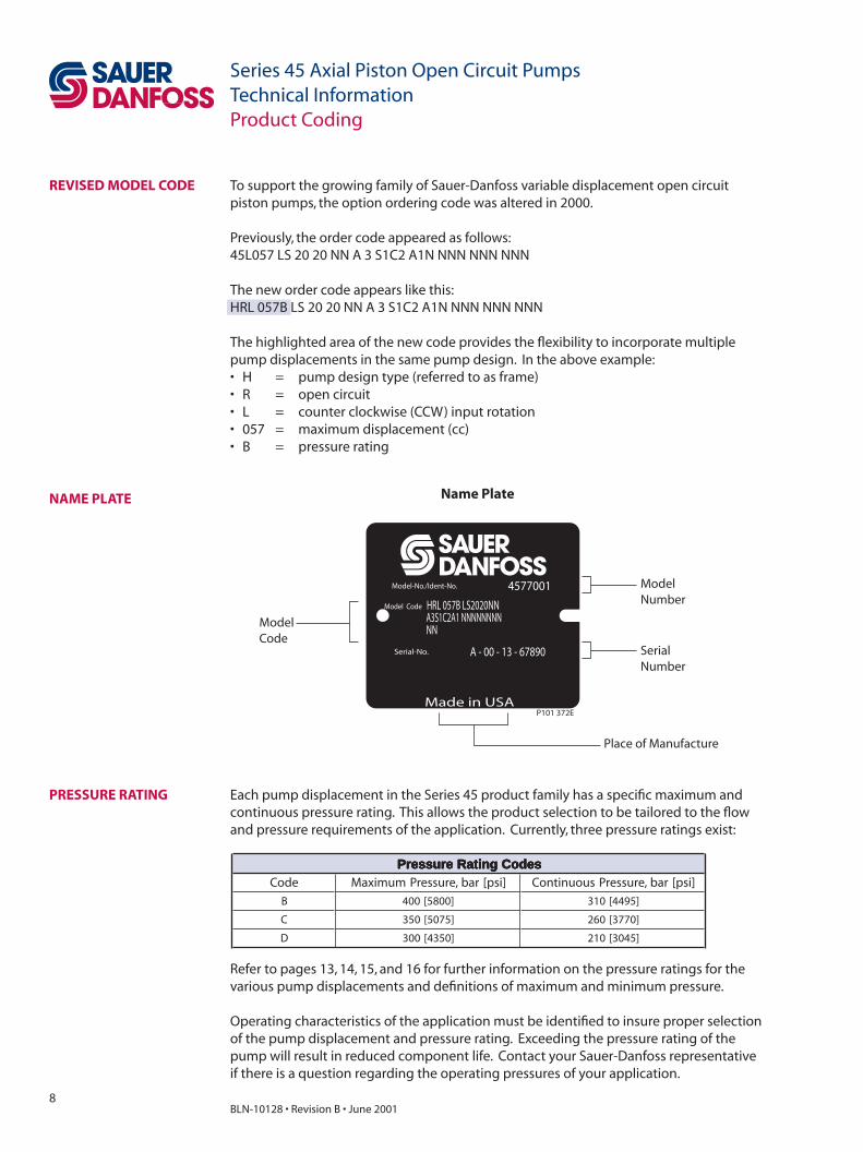
Series 45 Axial Piston Open Circuit PumpsTechnical InformationProduct Coding
Model-No./Ident-No.
Model Code
Serial-No.
Made in USA
Name Plate
Place of Manufacture
ModelNumber
SerialNumber
ModelCode
A - 00 - 13 - 67890
HRL 057B LS2020NNA3S1C2A1 NNNNNNNN
4577001
NN
P101 372E
To support the growing family of Sauer-Danfoss variable displacement open circuit piston pumps, the option ordering code was altered in 2000.
Previously, the order code appeared as follows:45L057 LS 20 20 NN A 3 S1C2 A1N NNN NNN NNN
The new order code appears like this:HRL 057B LS 20 20 NN A 3 S1C2 A1N NNN NNN NNN
The highlighted area of the new code provides the fl exibility to incorporate multiple pump displacements in the same pump design. In the above example: • H = pump design type (referred to as frame)• R = open circuit• L = counter clockwise (CCW) input rotation• 057 = maximum displacement (cc)• B = pressure rating
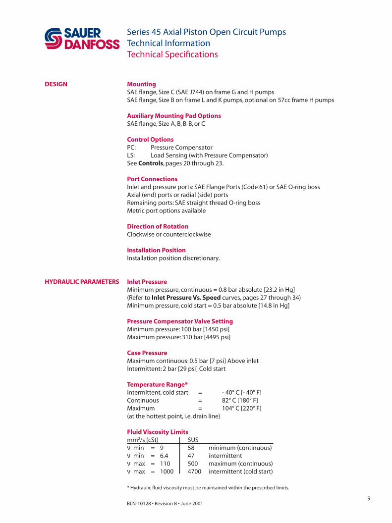
Refer to pages 13, 14, 15, and 16 for further information on the pressure ratings for the various pump displacements and defi nitions of maximum and minimum pressure.
Operating characteristics of the application must be identifi ed to insure proper selection of the pump displacement and pressure rating. Exceeding the pressure rating of the pump will result in reduced component life. Contact your Sauer-Danfoss representative if there is a question regarding the operating pressures of your application.
sedoCgnitaRerusserP sedoCgnitaRerusserP sedoCgnitaRerusserP sedoCgnitaRerusserP sedoCgnitaRerusserPedoC ]isp[rab,erusserPmumixaM ]isp[rab,erusserPsuounitnoC
B ]0085[004 ]5944[013
C ]5705[053 ]0773[062
D ]0534[003 ]5403[012
REVISED MODEL CODE
PRESSURE RATING Each pump displacement in the Series 45 product family has a specifi c maximum and continuous pressure rating. This allows the product selection to be tailored to the fl ow and pressure requirements of the application. Currently, three pressure ratings exist:
NAME PLATE
9BLN-10128 • Revision B • June 2001
Series 45 Axial Piston Open Circuit PumpsTechnical InformationTechnical Specifi cations
Mounting SAE fl ange, Size C (SAE J744) on frame G and H pumpsSAE fl ange, Size B on frame L and K pumps, optional on 57cc frame H pumps
Auxiliary Mounting Pad OptionsSAE fl ange, Size A, B, B-B, or C
Control OptionsPC: Pressure CompensatorLS: Load Sensing (with Pressure Compensator)See Controls, pages 20 through 23.
Port ConnectionsInlet and pressure ports: SAE Flange Ports (Code 61) or SAE O-ring bossAxial (end) ports or radial (side) portsRemaining ports: SAE straight thread O-ring bossMetric port options available
Direction of RotationClockwise or counterclockwise
Installation PositionInstallation position discretionary.
DESIGN
HYDRAULIC PARAMETERS Inlet PressureMinimum pressure, continuous = 0.8 bar absolute [23.2 in Hg](Refer to Inlet Pressure Vs. Speed curves, pages 27 through 34)Minimum pressure, cold start = 0.5 bar absolute [14.8 in Hg]
Pressure Compensator Valve SettingMinimum pressure: 100 bar [1450 psi]Maximum pressure: 310 bar [4495 psi]
Case PressureMaximum continuous: 0.5 bar [7 psi] Above inletIntermittent: 2 bar [29 psi] Cold start
Temperature Range*Intermittent, cold start = - 40° C [- 40° F]Continuous = 82° C [180° F]Maximum = 104° C [220° F](at the hottest point, i.e. drain line)
Fluid Viscosity Limitsmm2/s (cSt) SUSν min = 9 58 minimum (continuous)ν min = 6.4 47 intermittentν max = 110 500 maximum (continuous)ν max = 1000 4700 intermittent (cold start)
* Hydraulic fl uid viscosity must be maintained within the prescribed limits.

10BLN-10128 • Revision B • June 2001
Series 45 Axial Piston Open Circuit PumpsTechnical Information
FiltrationIt is imperative that only clean oil be allowed to enter the pump in order to prevent premature wear. System fi ltration capable of controlling the fl uid cleanliness to ISO 4406 class 18/13 or better is required.
Due to changes in pump inlet conditions, system aeration, and duty cycle, suction line fi lters are not recommended. Instead, a 125 µm (150 mesh) strainer located in the reservoir or in the pump inlet line is recommended to protect the pump from coarse particles.
The selection of a return fi lter depends on a number of factors including contamination ingression rate and the desired maintenance interval. Filters are selected to meet the above requirements using rating parameters of effi ciency and capacity.
Filter effi ciency may be measured using a Beta (β) ratio*. A fi lter with a β-ratio within the range of β10 = 10 or better is typically required.
Since each system is unique, the fi ltration requirement for that system will be unique and must be determined by test in each case. It is essential that monitoring of prototypes and evaluation of components and performance throughout the test program be the fi nal criteria for judging the adequacy of the fi ltration system. See Sauer-Danfoss publication BLN-9887 or 697581 and ATI-E 9201 for more information.
Technical Specifi cations
SYSTEM REQUIREMENTS
HYDRAULIC PARAMETERS(continued)
* Filter βx-ratio is a measure of fi lter effi ciency defi ned by ISO 4572. It is defi ned as the ratio of the number of
particles greater than a given size (x) upstream of the fi lter to number of particles greater than the same size
downstream of the fi lter. The βx-ratio applies to a specifi c particle size, measured in microns.
Hydraulic FluidsRatings and performance data for Series 45 products are based on operating with premium hydraulic fl uids containing oxidation, rust, and foam inhibitors.
These premium fl uids include premium turbine oils, API CD engine oils per SAE J183, M2C33F or G automatic transmission fl uids (ATF), Dexron II (ATF) meeting Allison C-3 or Caterpillar TO-2 requirements, and certain specialty agriculture tractor fl uids. For further information, see Sauer-Danfoss publication BLN-9887 or 697581.
Refer to publication ATI-E 9101 for information relating to biodegradable fl uids. Never mix hydraulic fl uids.
Contact your Sauer-Danfoss representative for more information regarding fl uids.

11BLN-10128 • Revision B • June 2001
Series 45 Axial Piston Open Circuit PumpsTechnical Information
Reservoir The function of the reservoir is to provide clean fl uid, dissipate heat, remove entrained air, and allow for fl uid volume changes associated with fl uid expansion and cylinder differential volumes.
Minimum reservoir capacity depends on the volume needed to cool the oil, hold the oil from all retracted cylinders, and allow expansion due to temperature changes. Normally, a capacity of 1 to 3 times the pump output fl ow (per minute) is satisfactory.
The reservoir outlet (to pump inlet) should be near the bottom of the reservoir, but far enough above the bottom to take advantage of gravity separation of foreign particles. It must always be covered with fl uid. The reservoir inlet (fl uid return) from the system should be below the fl uid level and be as far away as possible from the outlet port.
The reservoir oil levels must be maintained to allow adequate time for the entrained air to escape. A dwell time of 30 to 60 seconds is normally adequate.
Dwell time = Reservoir Capacity
Flow Rate
Case PressureCase fl ow is affected by the pump’s volumetric effi ciency and control fl ow (under steady state and transient conditions).
Under normal operating conditions, the maximum continuous case pressure must not be greater than 0.5 bar [7 psi] above the pump inlet pressure. Case pressure must never exceed 2 bar [30 psi] gauge pressure.
Temperature LimitsMaximum and continuous allowable temperature limits for petroleum based fl uids are found on page 8. These temperature limits apply at the hottest point in the unit, which is normally the case drain.
Technical Specifi cations
SYSTEM REQUIREMENTS(Continued)

12BLN-10128 • Revision B • June 2001
Series 45 Axial Piston Open Circuit PumpsTechnical InformationPump Installation and Line Sizing
The pump housing must be fi lled with clean fl uid during installation. The case drain line should be connected to the uppermost case drain port (L1 or L2) in order to keep the housing full of fl uid during operation.
The case drain line should be a separate line to allow unrestricted fl ow to the reservoir. It should connect at the lowest point in the reservoir (below the minimum reservoir fl uid level) and as far away from the reservoir outlet (pump inlet) connection as possible.The case drain line plumbing should be sized to limit case pressure to the values specifi ed on page 7.
Pump inlet line plumbing must be designed so that the inlet pressure (vacuum) is within the values listed on page 7. Inlet line losses must be considered. Methods for estimating these losses are shown in the following formulae.
PTotal = P1+P2+P3
where: P1 = Acceleration loss, bar [psi] P2 = Static head loss, bar [psi] P3 = Line losses, bar [psi]
P1 bar = l • sg • Dv 100 •Dt
P1 psi = l • sg • Dv 74 • Dt
where: l = Line length, m [ft] sg = Specifi c gravity Dv = Change in fl uid velocity, m/s [ft/s] Dt = Time interval for Dv, seconds
P2 bar = sg • h 10.19
P2 psi = sg • h 2.31
where: sg = Specifi c gravity h = Elevation change, m [ft]
P3 = Line losses due to hose friction, bends, fi ttings, etc.
EQUATIONS FOR ESTIMATING INLET LINE LOSSES
PUMP INSTALLATION

13BLN-10128 • Revision B • June 2001
Series 45 Axial Piston Open Circuit PumpsTechnical InformationTechnical Data
FRAME K AND L PUMPS snoitacificepSlacinhceTLdnaKemarF snoitacificepSlacinhceTLdnaKemarF snoitacificepSlacinhceTLdnaKemarF snoitacificepSlacinhceTLdnaKemarF snoitacificepSlacinhceTLdnaKemarF
stinUtnemecalpsiD
stinUC52L D03L C83K D54K
tnemecalpsiD mc 3 ni[ 3] ]35.1[52 ]38.1[03 ]23.2[83 ]57.2[54
deepStupnI
muminiM nim 1- )mpr( 005 005 005 005
deepStupnI *detaR nim 1- )mpr( 0023 0023 0562 0562deepStupnI
*mumixaM nim 1- )mpr( **0063 **0063 **0082 **0082
erusserPgnikroW)kaeP(mumixaM ]isp[rab ]5705[053 ]0534[003 ]5705[053 ]0534[003
erusserPgnikroWsuounitnoC ]isp[rab ]0773[062 ]5403[012 ]0773[062 ]5403[012
deepSdetaRtawolFnim/l
]nim/lagSU[
2.67
]3.02[
0.09
]0.42[
3.801
]9.82[
0.621
]6.33[
taeuqroTtupnIlaciteroehT
tnemecalpsiDmumixaM
rab/mN
]isp0001/ni·fbl[
593.0
]342[
774.0
]192[
506.0
]963[
617.0
]734[
ehtfoaitrenIfotnemoMssaM
straPgnitatoRlanretnI
m·gk 2
tf·fbl[ 2]
6100.0
]730.0[
5100.0
]530.0[
7100.0
]040.0[
0200.0
]740.0[
thgieW
detroPlaixA
stinU]bl[gk
91
]24[
91
]24[
91
]24[
91
]24[thgieW
detroPlaidaR
stinU]bl[gk
42
]35[
42
]35[
42
]35[
42
]35[
Displacement Piston
Cylinder Block Kit
Tapered RollerBearing
Valve Plate
Piston
Shaft Seal
Swashplate
Tapered RollerBearing
P101 373E
LS Adjustment Spring LS Spool
PC SpoolPC Adjustment Spring
* Refer to Speed Ratings, page 16.
** With pressurized Inlet.
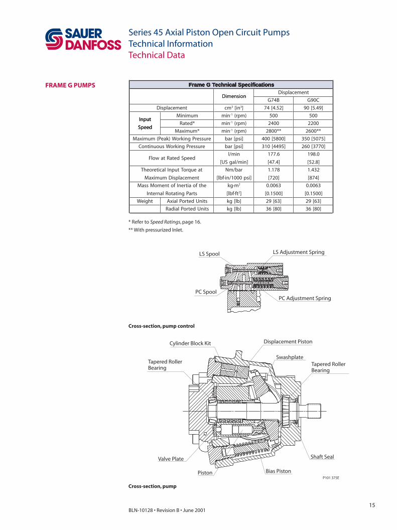
Cross-section, pump control
Cross-section, pump

14BLN-10128 • Revision B • June 2001
Series 45 Axial Piston Open Circuit PumpsTechnical Information
Displacement PistonCylinder Block Kit
Tapered RollerBearing
Valve Plate
Piston
Bias Piston
Shaft Seal
Swashplate
Tapered RollerBearing
P101 374E
LS SpoolLS Spring
PC Adjustment SpringPC Poppet
FRAME H PUMPS
Technical Data
snoitacificepSlacinhceTHemarF snoitacificepSlacinhceTHemarF snoitacificepSlacinhceTHemarF snoitacificepSlacinhceTHemarF snoitacificepSlacinhceTHemarF
noisnemiDtnemecalpsiD
noisnemiDB75H D57H
tnemecalpsiD mc 3 ni[ 3] ]84.3[75 ]75.4[57
tupnI
deepS
muminiM nim 1- )mpr( 005 005tupnI
deepS*detaR nim 1- )mpr( 0062 0042
tupnI
deepS*mumixaM nim 1- )mpr( **0023 **0082
erusserPgnikroW)kaeP(mumixaM ]isp[rab ]0085[004 ]0534[003
erusserPgnikroWsuounitnoC ]isp[rab ]5944[013 ]5403[012
deepSdetaRtawolFnim/l
]nim/lagSU[
2.841
]5.93[
0.081
]0.84[
taeuqroTtupnIlaciteroehT
tnemecalpsiDmumixaM
rab/mN
]isp0001/ni·fbl[
709.0
]455[
491.1
]627[
ehtfoaitrenIfotnemoMssaM
straPgnitatoRlanretnI
m·gk 2
tf·fbl[ 2]
3400.0
]4101.0[
3400.0
]4101.0[
thgieWstinUdetroPlaixA ]bl[gk ]35[42 ]35[42
thgieWstinUdetroPlaidaR ]bl[gk ]06[72 ]06[72
* Refer to Speed Ratings, page 16.
** With pressurized Inlet.
Cross-section, pump control
Cross-section, pump
15BLN-10128 • Revision B • June 2001
Series 45 Axial Piston Open Circuit PumpsTechnical Information
Displacement PistonCylinder Block Kit
Tapered RollerBearing
Valve Plate
Piston Bias Piston
Shaft Seal
SwashplateTapered RollerBearing
P101 375E
LS Adjustment SpringLS Spool
PC SpoolPC Adjustment Spring
FRAME G PUMPS
Technical Data
snoitacificepSlacinhceTGemarF snoitacificepSlacinhceTGemarF snoitacificepSlacinhceTGemarF snoitacificepSlacinhceTGemarF snoitacificepSlacinhceTGemarF
noisnemiDtnemecalpsiD
noisnemiDB47G C09G
tnemecalpsiD mc 3 ni[ 3] ]25.4[47 ]94.5[09
tupnI
deepS
muminiM nim 1- )mpr( 005 005tupnI
deepS*detaR nim 1- )mpr( 0042 0022
tupnI
deepS*mumixaM nim 1- )mpr( **0082 **0062
erusserPgnikroW)kaeP(mumixaM ]isp[rab ]0085[004 ]5705[053
erusserPgnikroWsuounitnoC ]isp[rab ]5944[013 ]0773[062
deepSdetaRtawolFnim/l
]nim/lagSU[
6.771
]4.74[
0.891
]8.25[
taeuqroTtupnIlaciteroehT
tnemecalpsiDmumixaM
rab/mN
]isp0001/ni·fbl[
871.1
]027[
234.1
]478[
ehtfoaitrenIfotnemoMssaM
straPgnitatoRlanretnI
m·gk 2
tf·fbl[ 2]
3600.0
]0051.0[
3600.0
]0051.0[
thgieW stinUdetroPlaixA ]bl[gk ]36[92 ]36[92
stinUdetroPlaidaR ]bl[gk ]08[63 ]08[63
* Refer to Speed Ratings, page 16.
** With pressurized Inlet.
Cross-section, pump control
Cross-section, pump
16BLN-10128 • Revision B • June 2001
Series 45 Axial Piston Open Circuit PumpsTechnical Information
DEFINITIONS Speed RatingsRated speed is the maximum speed recommended under full power conditions at which normal life can be expected.
The rated speed is valid for an inlet pressure of 1 bar [14.5 psi] absolute. All other operating conditions (e.g. fl uid viscosity and temperature) must be within recommended limits.
Maximum speed is the highest operating speed recommended and cannot be exceeded without reduction in the life of the product or risk of premature failure and loss of hydraulic power. Reductions in pump outlet fl ow and/or a pressurized inlet are required to achieve max speed.
Pressure LimitsSystem pressure is a dominant operating variable affecting hydraulic unit life.
Maximum (peak) working pressure is the highest pressure allowed and is controlled by the system relief valve. This pressure is determined by the maximum machine load demand. Exceeding this pressure will reduce pump life.
Continuous working pressure is the average regularly occurring operating pressure that should yield satisfactory product life. For all applications, the load should move below this pressure.
In order for Sauer-Danfoss representatives to calculate an appropriate design pressure, it is desirable to have a machine duty cycle with the percentage of time at various fl ows, pressures, and pump speeds. This method of selecting operating pressure is recommended whenever duty cycle information is available.
Technical Data
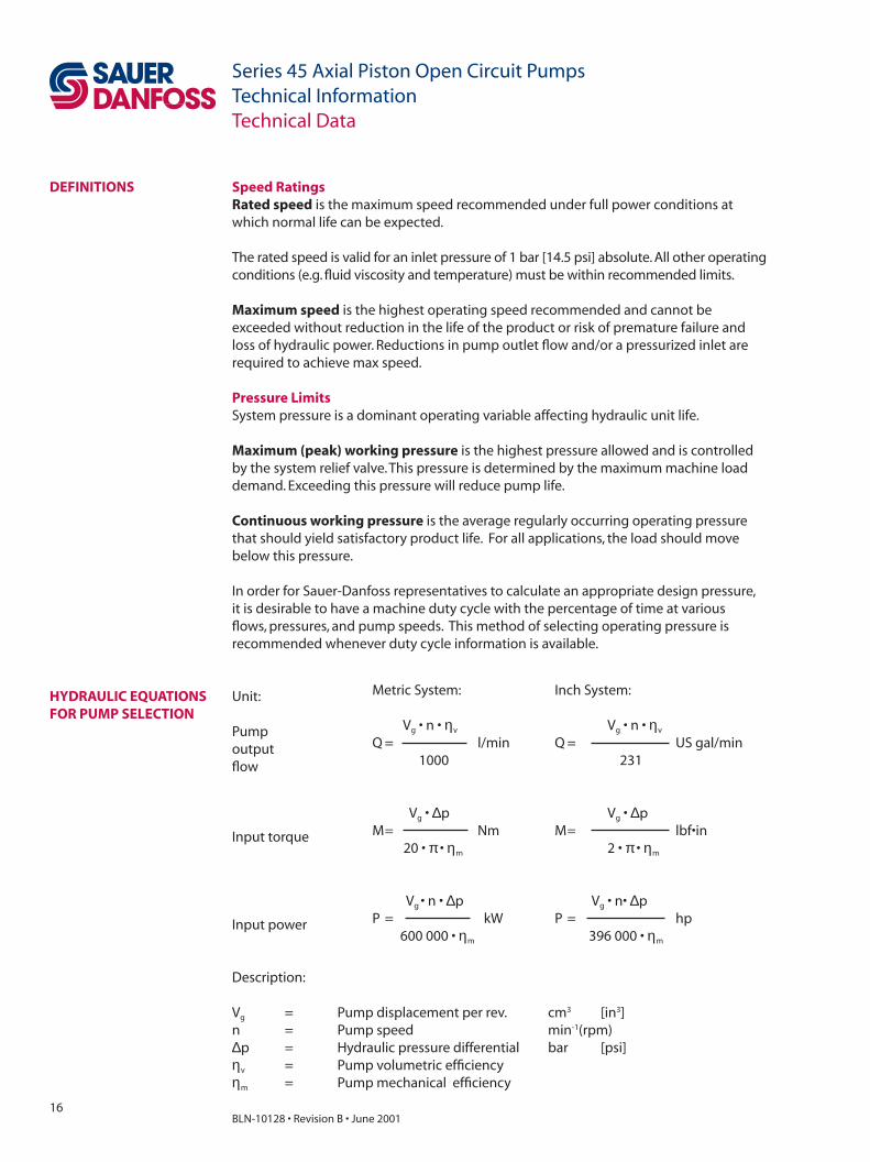
HYDRAULIC EQUATIONS FOR PUMP SELECTION
Description:
Vg = Pump displacement per rev. cm3 [in3]n = Pump speed min-1(rpm)∆p = Hydraulic pressure differential bar [psi]ηv = Pump volumetric effi ciencyηm = Pump mechanical effi ciency
Unit:
Pump outputfl ow
Input torque
Input power
Metric System:
Vg • n • ηv
Q = l/min 1000
Vg • ∆pM = Nm 20 • π • ηm
Vg • n • ∆p P = kW 600 000 • ηm
Inch System: Vg • n • ηv
Q = US gal/min 231
Vg • ∆pM = lbf•in 2 • π • ηm
Vg • n• ∆pP = hp 396 000 • ηm
17BLN-10128 • Revision B • June 2001
Series 45 Axial Piston Open Circuit PumpsTechnical InformationOptions
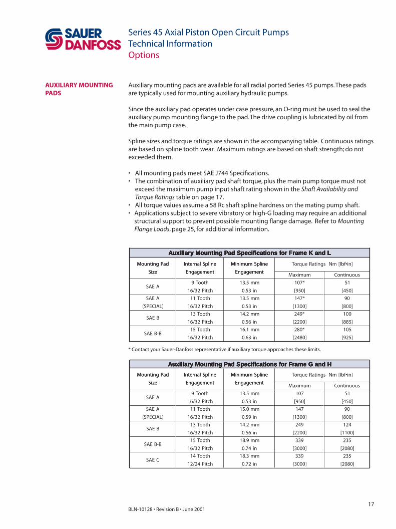
Auxiliary mounting pads are available for all radial ported Series 45 pumps. These pads are typically used for mounting auxiliary hydraulic pumps.
Since the auxiliary pad operates under case pressure, an O-ring must be used to seal the auxiliary pump mounting fl ange to the pad. The drive coupling is lubricated by oil from the main pump case.
Spline sizes and torque ratings are shown in the accompanying table. Continuous ratings are based on spline tooth wear. Maximum ratings are based on shaft strength; do not exceeded them.
• All mounting pads meet SAE J744 Specifi cations.• The combination of auxiliary pad shaft torque, plus the main pump torque must not exceed the maximum pump input shaft rating shown in the Shaft Availability and Torque Ratings table on page 17.• All torque values assume a 58 Rc shaft spline hardness on the mating pump shaft.• Applications subject to severe vibratory or high-G loading may require an additional
structural support to prevent possible mounting fl ange damage. Refer to Mounting Flange Loads, page 25, for additional information.
AUXILIARY MOUNTING PADS
HdnaGemarFrofsnoitacificepSdaPgnitnuoMyrailixuA HdnaGemarFrofsnoitacificepSdaPgnitnuoMyrailixuA HdnaGemarFrofsnoitacificepSdaPgnitnuoMyrailixuA HdnaGemarFrofsnoitacificepSdaPgnitnuoMyrailixuA HdnaGemarFrofsnoitacificepSdaPgnitnuoMyrailixuA
daPgnitnuoM
eziS
enilpSlanretnI
tnemegagnE
enilpSmuminiM
tnemegagnE
]ni•fbl[mNsgnitaReuqroTdaPgnitnuoM
eziS
enilpSlanretnI
tnemegagnE
enilpSmuminiM
tnemegagnEmumixaM suounitnoC
AEAShtooT9
hctiP23/61
mm5.31
ni35.0
701
]059[
15
]054[
AEAS
)LAICEPS(
htooT11
hctiP23/61
mm0.51
ni95.0
741
]0031[
09
]008[
BEAShtooT31
hctiP23/61
mm2.41
ni65.0
942
]0022[
421
]0011[
B-BEAShtooT51
hctiP23/61
mm9.81
ni47.0
933
]0003[
532
]0802[
CEAShtooT41
hctiP42/21
mm3.81
ni27.0
933
]0003[
532
]0802[
LdnaKemarFrofsnoitacificepSdaPgnitnuoMyrailixuA LdnaKemarFrofsnoitacificepSdaPgnitnuoMyrailixuA LdnaKemarFrofsnoitacificepSdaPgnitnuoMyrailixuA LdnaKemarFrofsnoitacificepSdaPgnitnuoMyrailixuA LdnaKemarFrofsnoitacificepSdaPgnitnuoMyrailixuA
daPgnitnuoM
eziS
enilpSlanretnI
tnemegagnE
enilpSmuminiM
tnemegagnE
]ni•fbl[mNsgnitaReuqroTdaPgnitnuoM
eziS
enilpSlanretnI
tnemegagnE
enilpSmuminiM
tnemegagnEmumixaM suounitnoC
AEAShtooT9
hctiP23/61
mm5.31
ni35.0
*701
]059[
15
]054[
AEAS
)LAICEPS(
htooT11
hctiP23/61
mm5.31
ni35.0
*741
]0031[
09
]008[
BEAShtooT31
hctiP23/61
mm2.41
ni65.0
*942
]0022[
001
]588[
B-BEAShtooT51
hctiP23/61
mm1.61
ni36.0
*082
]0842[
501
]529[
* Contact your Sauer-Danfoss representative if auxiliary torque approaches these limits.

18BLN-10128 • Revision B • June 2001
Series 45 Axial Piston Open Circuit PumpsTechnical Information
Pump mounting fl anges and shafts with the dimensions noted in the accompanying drawing are compatible with the auxiliary mounting pads on the Series 45 pumps.
Mating Auxiliary Pumps
Dimensions in mm [in]
"P" DIA.+0, -.05[+.000, -.002]
"F" MIN. SPLINE ENGAGEMENTFO R FULL TORQUE RATING
"E"MAX.
MOUNTINGFLANGE
(REF)
"D"MAX.
WITHUNDERCUT
WITHOUTUNDERCUT
"C"MAX.
"B"MAX.
.8 MAX. R PREFERRED[.03]
2.3 [.090] RECOMMENDEDCUTTER CLEARANCE
COUPLING
mm[in.]
P101 079E
snoisnemiD snoisnemiD snoisnemiD snoisnemiD snoisnemiDegnalF "P" "B" "C" "D" "E" "F"
EAS
A
55.28
]052.3[
053.6
]052.0[
07.21
]005.0[
02.85
]092.2[
00.51
]095.0[
05.31
]035.0[
EAS
B
06.101
]000.4[
056.9
]083.0[
02.51
]006.0[
01.35
]090.2[
05.71
]096.0[
02.41
]065.0[
EAS
C
00.721
]000.5[
07.21
]005.0[
73.32
]029.0[
06.55
]091.2[
05.03
]002.1[
03.81
]027.0[
AUXILIARY MOUNTING PADS (continued)
Options

19BLN-10128 • Revision B • June 2001
Series 45 Axial Piston Open Circuit PumpsTechnical Information
INPUT SHAFTS Series 45 pumps are available with a variety of splined, parallel, and tapered end shafts. Nominal shaft sizes and torque ratings are shown in the accompanying table.
Continuous torque ratings for splined shafts are based on spline tooth wear, and assume the mating spline has a minimum full spline depth hardness of 55 Rc and good lubrication. Torque ratings of spline shafts are based on no external radial loads.
Note: Recommended mating splines for Series 45 splined input shafts should be in accordance with
ANSI B92.1 class 5. Sauer-Danfoss external splines are modifi ed class 5 fi llet root side fi t. The external spline
major diameter and circular tooth thickness dimensions are reduced in order to assure a clearance fi t with
the mating spline.
DISPLACEMENT LIMITER
sgnitaReuqroTdnaytilibaliavAtfahS sgnitaReuqroTdnaytilibaliavAtfahS sgnitaReuqroTdnaytilibaliavAtfahS sgnitaReuqroTdnaytilibaliavAtfahS sgnitaReuqroTdnaytilibaliavAtfahS
snoitpOtfahSgnitaR
]ni•fbl[mN
emarFsnoitpOtfahS
gnitaR]ni•fbl[mN LdnaK H G
2C2D
htooT31,enilpS
hctiP23/61
)ylnognisuoh'B'EAS(
mumixaM
suounitnoC
]5342[572
]588[001
]5942[282
]009[201elbaliavAtoN
1ShtooT41,enilpS
hctiP42/21
mumixaM
suounitnoCelbaliavAtoN
]0056[437
]0052[382
]0056[437
]0052[382
3C3D
htooT51,enilpS
hctiP23/61
)ylnognisuoh'B'EAS(
mumixaM
suounitnoC
]0453[004
]0581[012
]0023[263
]0071[291elbaliavAtoN
2ShtooT71,enilpS
hctiP42/21
mumixaM
suounitnoCelbaliavAtoN elbaliavAtoN
]0009[7101
]0044[794
0T8:1,derepaT
retemaiD].ni52.1[mm57.13mumixaM elbaliavAtoN ]5946[437 ]5946[437
4K4L
lellaraP
retemaiD].ni52.1[mm57.13mumixaM elbaliavAtoN ]0085[556 ]5946[437
1T8:1,derepaT
retemaiD].ni0.1[mm4.52mumixaM ]0273[024 elbaliavAtoN elbaliavAtoN
2T8:1,derepaT
retemaiD].ni578.0[mm22.22mumixaM ]5432[562 elbaliavAtoN elbaliavAtoN
Series 45 - H57, H75, G74, and G90 pumps are available with an optional mechanical maximum displacement (stroke) limiter. The maximum displacement of the pump can be limited to any value from maximum to 75% displacement.
Series 45- K38, K45, L25, L30 pumps only have fi xed displacement limiters. Consult the model code or price list for option availability.
Options

20BLN-10128 • Revision B • June 2001
Series 45 Axial Piston Open Circuit PumpsTechnical Information
PRESSURE COMPENSATOR (PC) CONTROL
The pressure compensator control is designed to limit the maximum pressure in the hydraulic circuit by varying the output fl ow of the pump. This type of control is typically used with closed center valves.
When system pressure at the pump outlet drops below the compensator setting, the control will increase the pump displacement to maximum (maximum output fl ow). Once system pressure reaches the compensator setting, the
00
Q max
Pressure
Flo
w
P101 166E
Pressure Compensator Control Characteristics
emiTyrevoceR/esnopseRlortnoCCP emiTyrevoceR/esnopseRlortnoCCP emiTyrevoceR/esnopseRlortnoCCP emiTyrevoceR/esnopseRlortnoCCP emiTyrevoceR/esnopseRlortnoCCP
)sm( 52 03 83 54 75 47 57 09
esnopseR 03 03 03 03 03 53 03 04
yrevoceR 09 001 501 011 521 031 031 041
egnaRgnitteSlortnoCCP egnaRgnitteSlortnoCCP egnaRgnitteSlortnoCCP egnaRgnitteSlortnoCCP egnaRgnitteSlortnoCCP
]isp[rab 52 03 83 54 75 47 57 09
muminiM001
]0541[
001
]0541[
001
]0541[
001
]0541[
001
]0541[
001
]0541[
001
]0541[
001
]0541[
mumixaM062
]0773[
012
]5403[
062
]0773[
012
]5403[
013
]5944[
013
]5944[
012
]5403[
062
]0773[
Controls
The pressure compensator setting is externally adjustable. The setting range for the pressure compensator is shown in the table below.
A remote pressure compensator control can be added to the system by connecting an appropriate external pressure control valve to the load sense port (port X). This will allow the pressure compensator setting to be controlled mechanically or electrically below the setting of the integral pressure compensator pilot valve. The external valve and its plumbing should be sized for a pilot oil fl ow of 3.8 l/min [1 US gal/min].
A low standby pressure can be provided by venting the remote compensator port to reservoir through an external 2-way on – off valve (not shown). When this valve is open, the pump standby pressure will be 15 to 20 bar [215 to 300 psi].
For additional system protection, install a relief valve in the pump outlet line.
control regulates pump displacement to produce an output fl ow which limits system pressure to the compensator setting. Control response (off-stroke) and recovery (on-stroke) times are shown in the table below.
REMOTE PC CONTROL

21BLN-10128 • Revision B • June 2001
Series 45 Axial Piston Open Circuit PumpsTechnical Information
Ports:B = Main pressure lineS = Suction line L1, L2 = Case drain lines M2 = Gauge port for port BM4 = Gauge port - servo pressure1 = Gain orifi ce
SL1,L2
M2
M4
B
P101 083
1
Controls
PC CONTROL SCHEMATIC DIAGRAMS
PC Control Schematic for Frame G, K, and L
B X
M2
L1,L2 S
M4
P101 182E
1
2
PC Control Schematic for Frame H
Ports:B = Main pressure lineS = Suction line L1, L2 = Case drain lines M2 = Gauge port for port BM4 = Gauge port - servo pressure1 = Gain orifi ce2 = Pilot orifi ce
SL1,L2
M2
M4
B
X
P101 104E
1
3
Remote PC Control Schematic
for Frames G, K, and L
Remote PC Control Schematic for Frame H
Ports:B = Main pressure lineS = Suction line L1, L2 = Case drain lines X = Load sensing pressure portM2 = Gauge port for port BM4 = Gauge port - servo pressure1 = Gain orifi ce3 = Bleed orifi ce (optional)
M2
B
L1,L2 S
X
M4
P101 126E
1
2
Ports:B = Main pressure lineS = Suction line L1, L2 = Case drain lines X = Load sensing pressure portM2 = Gauge port for port BM4 = Gauge port - servo pressure1 = Gain orifi ce2 = Pilot orifi ce
REMOTE PC CONTROL SCHEMATIC DIAGRAMS

22BLN-10128 • Revision B • June 2001
Series 45 Axial Piston Open Circuit PumpsTechnical Information
LOAD SENSING (LS) CONTROL
The load sensing control is designed to match pump outlet fl ow with system demand. This control option is typically used with closed center, load sensing directional control valves.
When the control valve is centered, the load sensing port on the pump is drained to the reservoir through the a bleed orifi ce located either in the control valve or the pump control. This maintains a standby pressure at the pump outlet
00
Q max
Pressure
Flo
w
P101 167E
equal to the load sensing setting.
When the control valve is actuated, the load sensing port (port ‘X’) is connected to load pressure. The control then adjusts the pump output fl ow to maintain a constant pressure drop – equal to the load sensing setting – across the control valve. The pump thereby provides fl ow to the load as demanded by the control valve position. Control response (off-stroke) and recovery (on-stroke) times are shown in the table below.
Load Sensing Control Characteristics
A pressure compensator valve is built into the load sensing control. When the pump outlet pressure reaches the pressure compensator setting, the pump reduces its displacement to limit the system pressure. Operation of the pressure compensator valve is similar to the PC control.
The load sensing setting is externally adjustable. The setting range for the load sensing control is shown in the table below.
emiTyrevoceR/esnopseRlortnoCgnisneSdaoL emiTyrevoceR/esnopseRlortnoCgnisneSdaoL emiTyrevoceR/esnopseRlortnoCgnisneSdaoL emiTyrevoceR/esnopseRlortnoCgnisneSdaoL emiTyrevoceR/esnopseRlortnoCgnisneSdaoL
)sm( 52 03 83 54 75 47 57 09
esnopseR 02 02 03 03 03 53 03 04
yrevoceR 07 07 08 08 09 001 59 031
egnaRgnitteSlortnoCgnisneSdaoL egnaRgnitteSlortnoCgnisneSdaoL egnaRgnitteSlortnoCgnisneSdaoL egnaRgnitteSlortnoCgnisneSdaoL egnaRgnitteSlortnoCgnisneSdaoL
]isp[rab 52 03 83 54 75 47 57 09
muminiM21
]571[
21
]571[
21
]571[
21
]571[
7
]001[
01
]571[
7
]001[
01
]571[
mumixaM63
]225[
63
]225[
63
]225[
63
]225[
03
]534[
03
]534[
03
]534[
03
]534[
Controls

23BLN-10128 • Revision B • June 2001
Series 45 Axial Piston Open Circuit PumpsTechnical Information
SL1,L2
M2
M4
B
X
P101 105E
1
3
M2
B
L1,L2 S
X
M4
*
*optional
P101 108
2
1
Ports:B = Main pressure lineS = Suction line L1, L2 = Case drain lines X = Load sensing pressure portM2 = Gauge port for port BM4 = Gauge port - servo pressure1 = Gain orifi ce3 = Bleed orifi ce (optional)
Ports:B = Main pressure lineS = Suction line L1, L2 = Case drain lines X = Load sensing pressure portM2 = Gauge port for port BM4 = Gauge port - servo pressure2 = Pilot orifi ce3 = Bleed orifi ce (optional)
Load Sensing Control Schematic Diagram
Frames L, K, and G
Load Sensing Control Schematic Diagram
Frame H
LS CONTROL SCHEMATIC DIAGRAMS
Controls

24BLN-10128 • Revision B • June 2001
Series 45 Axial Piston Open Circuit PumpsTechnical InformationLoads and Life
SHAFT LOADS
Normal bearing B10 life in hours is indicated in the table below. These values are calculated using a weighted average pressure, 1800 rpm shaft speed, and no external shaft side load.
0 Re
180 Re
90 Re 270 Re T inT out
L
Re
Axis of Swashplate Rotation
Control
Mounting Flange
Front View Section View150˚ 210˚
P101 080EExternal Shaft Load Orientation
efiLgniraeB efiLgniraeB efiLgniraeB efiLgniraeB efiLgniraeB
BefiLgniraeB01
sruoHtnemecalpsiD
BefiLgniraeB01
sruoH52 03 83 54 75 47 57 09
]isp0302[rab041ta 00194 00642 00353 00691 21792 38314 55701 74891
]isp5403[rab012ta 00141 0327 00411 0026 4386 8409 4742 9334
]isp0773[rab062ta 0956 - 0785 - 1513 2604 - 8491
]isp5944[rab013ta - - - - 6661 1012 - -
sdaoLtfahSlanretxEelbawollAmumixaM sdaoLtfahSlanretxEelbawollAmumixaM sdaoLtfahSlanretxEelbawollAmumixaM sdaoLtfahSlanretxEelbawollAmumixaM sdaoLtfahSlanretxEelbawollAmumixaM
epyTdaoLtnemecalpsiD
epyTdaoL52 03 83 54 75 47 57 09
tnemoMlanretxE
M(e
]ni•fbl[mN–)
16
]045[
16
]045[
67
]376[
67
]376[
622
]0002[
003
]5562[
622
]0002[
003
]5562[
nItsurhTtfahSmumixaM
T(nI
]fbl[N–)
0001
]522[
0001
]522[
0021
]072[
0021
]072[
0022
]005[
0092
]056[
0022
]005[
0092
]056[
tuOtsurhTtfahSmumixaM
T(tuo
]fbl[N–)
0001
]522[
0001
]522[
0021
]072[
0021
]072[
0022
]005[
0092
]056[
0022
]005[
0092
]056[
Series 45 pumps are designed with bearings that can accept external some radial and thrust loads. The external radial shaft load limits are a function of the load position and orientation, and the operating conditions of the pump.
The maximum allowable radial side load (Re), based on the maximum external moment (Me) and the distance (L) from the mounting fl ange to the load, may be determined from the table and diagram below. Thrust (axial) load limits are also shown.
Maximum Allowable Radial Side Load, Re = Me / L
All external shaft loads will have an effect on bearing life. In applications where external shaft loads can not be avoided, bearing life may be maximized by orientating the load between the 150 and 210 degree positions, as shown.
Tapered input shafts or clamp-type couplings are recommended for applications where radial shaft side loads are present.
BEARING LIFE

25BLN-10128 • Revision B • June 2001
Series 45 Axial Piston Open Circuit PumpsTechnical Information
MOUNTING FLANGE LOADS
Adding tandem mounted auxiliary pumps and/or subjecting pumps to high shock loads may result in excessive loading of the mounting fl ange. The overhung load moment for multiple pump mounting may be estimated as shown in the accompanying fi gure.
ESTIMATING OVERHUNG LOAD MOMENTS
mounting flange
CGpump 1
L1L2
CGpump 2
P101 081E
W = Weight of pumpL = Distance from mounting fl ange to pump center of gravity (refer to pump
installation drawings)MS = GS (W1L1 + W2L2 + ... +WnLn)MC = GC (W1L1 + W2L2 + ... +WnLn)Where:MS = Shock load momentMc = Continuous load momentGs = Maximum shock acceleration (gs)Gc = Continuous (vibratory) acceleration (gs)
Allowable overhung load moment values are shown in the accompanying table. Exceeding these values will require additional pump support.
stnemoMdaoLgnuhrevOelbawollA stnemoMdaoLgnuhrevOelbawollA stnemoMdaoLgnuhrevOelbawollA stnemoMdaoLgnuhrevOelbawollA stnemoMdaoLgnuhrevOelbawollA
emarF egnalFM(tnemoMsuounitnoC
c) M(tnemoMdaoLkcohS
c)
emarF egnalFmN ]ni•fbl[ mN ]ni•fbl[
LdnaK llA 5001 ]0098[ 0553 ]00413[
H
llA 088 ]00001[ 0903 ]00053[
H egnalfBdeifidoM 047 ]0056[ 0062 ]00032[H
egnalfBdradnatS 047 ]0056[ 0062 ]00032[
G llA 0851 ]00041[ 0565 ]00005[
Overhung Load Distance From Mounting Flange
Loads and Life

26BLN-10128 • Revision B • June 2001
Series 45 Axial Piston Open Circuit PumpsTechnical InformationSound Levels
The accompanying table includes sound levels measured in dB(A) at 1.52 meter [5 ft.] from the pump in a semi-anechoic chamber. Anechoic levels can be estimated by subtracting 3 dB(A) from these values.
)A(BdsleveLdnuoS )A(BdsleveLdnuoS )A(BdsleveLdnuoS )A(BdsleveLdnuoS )A(BdsleveLdnuoS
.lpsiD]isp5403[rab012 ]isp0773[rab062 ]isp5944[rab013
.lpsiDmpr0081 detaR mpr0081 detaR mpr0081 detaR
52 86 27 96 37 - -
03 96 37 - - - -
83 96 37 07 47 - -
54 07 47 - - - -
75 27 57 37 67 47 77
47 87 18 77 97 87 08
57 47 77 - - - -
09 77 97 87 08 - -
Noise is unwanted sound. Fluid power systems create noise. There are many techniques available to minimize noise. Understanding how it’s generated and transmitted is necessary to apply these methods effectively.
Noise energy is transmitted as fl uid borne noise (pressure ripple) or structure borne noise. Pressure ripple is the result of the number of pumping elements (pistons) delivering oil to the outlet and the pump’s ability to gradually change the volume of each pumping element from low to high pressure. Pressure ripple is affected by the compressibility of the oil as each pumping element discharges into the outlet of the pump. Pressure pulsations travel along hydraulic lines at the speed of sound (about 1400 m/s in oil) until there is a change in the system (such as an elbow fi tting). Thus, the pressure pulsation amplitude varies with overall line length and position.
Structure borne noise may be transmitted wherever the pump casing is connected to the rest of the system.
The way circuit components respond to excitation depends on their size, form, and mounting. Because of this, a system line may actually have a greater noise level than the pump. To minimize noise, use:• fl exible hoses (if you must use steel plumbing, clamp the lines) • fl exible (rubber) mounts
SOUND LEVELS
27BLN-10128 • Revision B • June 2001
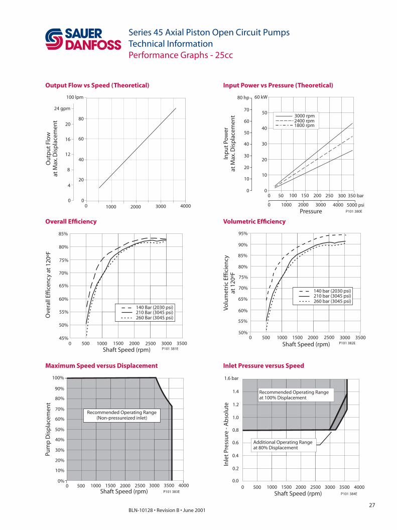
Series 45 Axial Piston Open Circuit PumpsTechnical InformationPerformance Graphs - 25cc
Output Flow vs Speed (Theoretical) Input Power vs Pressure (Theoretical)
Overall Effi ciency Volumetric Effi ciency
Maximum Speed versus Displacement Inlet Pressure versus Speed
0 50 100 150 200 250 300 350 bar
Pressure0 1000 2000 3000 4000 5000 psi
00
10
20
30
40
50
60 kW
10
20
30
40
50
60
70
80 hp
Inp
ut
Pow
erat
Max
.Dis
pla
cem
ent
1800 rpm2400 rpm3000 rpm
P101 380E
00 1000 2000 3000
0
420
8
4012
16 60
2080
24 gpm
100 lpm
Ou
tpu
t Fl
ow
at M
ax.D
isp
lace
men
t
4000
P101 383E
0 500 1000 1500 2000 2500 3000 3500Shaft Speed (rpm)
100%
90%
80%
70%
60%
50%
40%
30%
20%
10%
0%
Pum
pD
isp
lace
men
t
Recommended Operating Range(Non-pressureized inlet)
4000 2500 30000.0
0.2
0.4
0.6
0.8
1.0
1.2
1.6 bar
Shaft Speed (rpm)
Inle
t Pr
essu
re -
Ab
solu
te
0 500 1000 1500 2000P101 384E
3500
Recommended Operating Rangeat 100% Displacement
Additional Operating Rangeat 80% Displacement
4000
1.4
95%
80%
75%
70%
60%Volu
met
ric
Effic
ien
cyat
120
ºF
0 500 1000 1500 2000 2500 3000 3500
Shaft Speed (rpm) P101 382E
50%
140 bar (2030 psi)210 bar (3045 psi)260 bar (3045 psi)
90%
85%
65%
55%
45%
60%
65%
70%
75%
Ove
rall
Effic
ency
at
120º
F
Shaft Speed (rpm)3500300025002000150010005000
P101 381E
140 Bar (2030 psi)210 Bar (3045 psi)260 Bar (3045 psi)
85%
80%
55%
50%

28BLN-10128 • Revision B • June 2001
Series 45 Axial Piston Open Circuit PumpsTechnical InformationPerformance Graphs - 30cc
Output Flow vs Speed (Theoretical) Input Power vs Pressure (Theoretical)
Overall Effi ciency Volumetric Effi ciency
Maximum Speed versus Displacement Inlet Pressure versus Speed
0 50 100 150 200 250 300 350 bar
Pressure0 1000 2000 3000 4000 5000 psi
00
10
20
30
40
50
60 kW
10
20
30
40
50
60
70
80 hp
Inp
ut
Pow
erat
Max
.Dis
pla
cem
ent
1800 rpm2400 rpm3000 rpm
P101 386EShaft Speed (rpm)
00 1000 2000 3000
0
420
8
4012
16 60
2080
28 gpm
120 lpm
Ou
tpu
t Fl
ow
at M
ax.D
isp
lace
men
t
P101 385E
4000
100
24
P101 389E
0 500 1000 1500 2000 2500 3000 3500Shaft Speed (rpm)
100%
90%
80%
70%
60%
50%
40%
30%
20%
10%
0%
Pum
pD
isp
lace
men
t
Recommended Operating Range(Non-pressureized inlet)
4000 2500 30000.0
0.2
0.4
0.6
0.8
1.0
1.2
1.6 bar
Shaft Speed (rpm)
Inle
t Pr
essu
re -
Ab
solu
te
0 500 1000 1500 2000P101 390E
3500
Recommended Operating Rangeat 100% Displacement
Additional Operating Rangeat 80% Displacement
4000
1.4
100%
90%
80%
85%
75%
Volu
met
ric
Effic
ien
cyat
120
ºF
0 500 1000 1500 2000 2500 3000 3500
Shaft Speed (rpm)
140 Bar (2030 psi)210 Bar (3045 psi)
P101 388E
95%
60%
65%
70%
75%
85%
Ove
rall
Effic
ien
cy a
t 12
0ºF
Shaft Speed (rpm)3500300025002000150010005000
210 Bar (3045 psi)140 Bar (2030 psi)
P101 387E
80%

29BLN-10128 • Revision B • June 2001
Series 45 Axial Piston Open Circuit PumpsTechnical InformationPerformance Graphs - 38cc
Output Flow vs Speed (Theoretical) Input Power vs Pressure (Theoretical)
Overall Effi ciency Volumetric Effi ciency
Maximum Speed versus Displacement Inlet Pressure versus Speed
Shaft Speed (rpm)
00 1000 2000 3000
0
420
8
4012
16 60
2080
28 gpm
120 lpm
Ou
tpu
t Fl
ow
at M
ax.D
isp
lace
men
t
P101 391E
4000
100
24
0 50 100 150 200 250 300 350 bar
Pressure0 1000 2000 3000 4000 5000 psi
00
20
40
60
80
100
120 kW
20
40
60
80
100
120
140
160 hp
Inp
ut
Pow
erat
Max
.Dis
pla
cem
ent
1800 rpm2300 rpm2800 rpm
P101 392E
0 500 1000 1500 2000 2500 30000.0
0.2
0.4
0.6
0.8
1.0
1.2
1.6 bar
Shaft Speed (rpm)
Inle
t Pr
essu
re -
Ab
solu
te
Additional Operating Rangeat 80% Displacement
Recommended Operating Rangeat 100% Displacement
P101 396E
1.4
60%
65%
70%
75%
80%
Ove
rall
Effic
ency
at
120º
F
Shaft Speed (rpm)3500300025002000150010005000
P101 393E
140 Bar (2030 psi)210 Bar (3045 psi)260 Bar (3045 psi)
90%
85%
100%
90%
85%
80%
75%
Volu
met
ric
Effic
ien
cyat
120
ºF
0 500 1000 1500 2000 2500 3000 3500
Shaft Speed (rpm) P101 394E
70%
140 bar (2030 psi)210 bar (3045 psi)260 bar (3045 psi)
95%
P101 395E
0 500 1000 1500 2000 2500 3000Shaft Speed (rpm)
100%
90%
80%
70%
60%
50%
40%
30%
20%
10%
0%
Pum
pD
isp
lace
men
t
Recommended Operating Range(Non-pressureized inlet)

30BLN-10128 • Revision B • June 2001
Series 45 Axial Piston Open Circuit PumpsTechnical InformationPerformance Graphs - 45cc
Output Flow vs Speed (Theoretical) Input Power vs Pressure (Theoretical)
Overall Effi ciency Volumetric Effi ciency
Maximum Speed versus Displacement Inlet Pressure versus Speed
Shaft Speed (rpm)
00 1000 2000 3000
0
840
16
8024
12032
160
48 gpm
200 lpm
Ou
tpu
t Fl
ow
at M
ax.D
isp
lace
men
t
P101 397E
4000
40
0 50 100 150 200 250 300 350 bar
Pressure0 1000 2000 3000 4000 5000 psi
00
20
40
60
80
100
120 kW
20
40
60
80
100
120
140
160 hp
Inp
ut
Pow
erat
Max
.Dis
pla
cem
ent
1800 rpm2300 rpm2800 rpm
P101 398E
P101 401E
0 500 1000 1500 2000 2500 3000Shaft Speed (rpm)
100%
90%
80%
70%
60%
50%
40%
30%
20%
10%
0%
Pum
pD
isp
lace
men
t
Recommended Operating Range(Non-pressureized inlet)
0 500 1000 1500 2000 2500 30000.0
0.2
0.4
0.6
0.8
1.0
1.2
1.6 bar
Shaft Speed (rpm)
Inle
t Pr
essu
re -
Ab
solu
te
Additional Operating Rangeat 80% Displacement
Recommended Operating Rangeat 100% Displacement
P101 402E
1.4
65%
70%
75%
80%
90%
Ove
rall
Effic
ency
at
120º
F
Shaft Speed (rpm)3500300025002000150010005000
210 Bar (3045 psi)140 Bar (2030 psi)
P101 399E
85%
100%
90%
80%
85%
75%
Volu
met
ric
Effic
ien
cyat
120
ºF
0 500 1000 1500 2000 2500 3000 3500
Shaft Speed (rpm)
140 Bar (2030 psi)210 Bar (3045 psi)
P101 400E
95%
31BLN-10128 • Revision B • June 2001
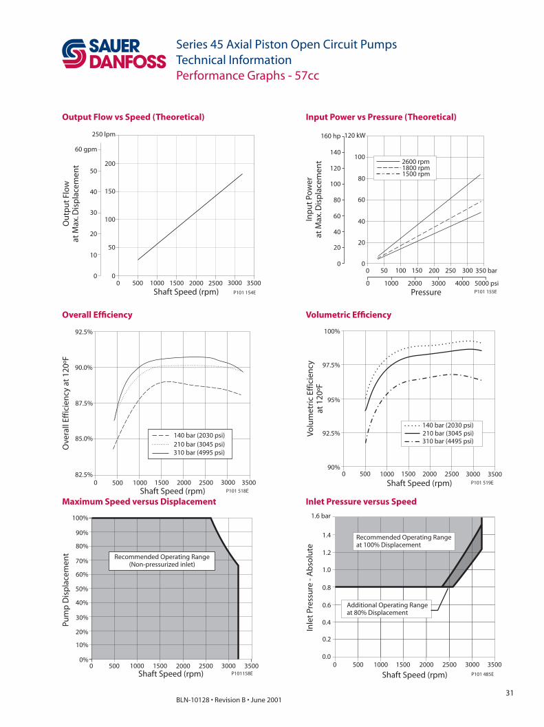
Series 45 Axial Piston Open Circuit PumpsTechnical InformationPerformance Graphs - 57cc
Output Flow vs Speed (Theoretical) Input Power vs Pressure (Theoretical)
Overall Effi ciency Volumetric Effi ciency
Maximum Speed versus Displacement Inlet Pressure versus Speed
P101 154E
0 500 1000 1500 2000 3000 35002500Shaft Speed (rpm)
0
50
100
150
200
250 lpm
0
10
30
20
40
50
60 gpm
Ou
tpu
t Fl
ow
at M
ax.D
isp
lace
men
t
P101 155E
0 1000 2000 3000 4000 5000 psi
Pressure
0 50 100 150 200 250 300 350 bar0
20
40
60
80
100
120 kW
0
20
40
60
80
100
120
140
160 hp
Inp
ut
Pow
erat
Max
.Dis
pla
cem
ent 2600 rpm
1800 rpm1500 rpm
0 500 1000 1500 2000 2500 3000 3500Shaft Speed (rpm) P101 518E
82.5%
85.0%
87.5%
90.0%
92.5%
Ove
rall
Effic
ien
cy a
t 12
0ºF
140 bar (2030 psi)210 bar (3045 psi)310 bar (4995 psi)
0 500 1000 1500 2000 2500 3000 3500
Shaft Speed (rpm) P101 519E
90%
92.5%
95%
97.5%
100%
Volu
met
ric
Effic
ien
cyat
120
ºF
140 bar (2030 psi)210 bar (3045 psi)310 bar (4495 psi)
P101158EShaft Speed (rpm)0 500 1000 1500 2000 2500 3000 3500
Recommended Operating Range(Non-pressurized inlet)
Pum
p D
isp
lac e
men
t
0%
10%
20%
30%
40%
50%
60%
70%
80%
90%
100%
P101 485EShaft Speed (rpm)0 500 1000 1500 2000 2500 3000 3500
Inle
t Pr
essu
re -
Ab
solu
te
0.0
0.2
0.4
0.6
0.8
1.0
1.2
1.6 bar
Recommended Operating Rangeat 100% Displacement
Additional Operating Rangeat 80% Displacement
1.4

32BLN-10128 • Revision B • June 2001
Series 45 Axial Piston Open Circuit PumpsTechnical InformationPerformance Graphs - 74cc
Output Flow vs Speed (Theoretical) Input Power vs Pressure (Theoretical)
Overall Effi ciency Volumetric Effi ciency
Maximum Speed versus Displacement Inlet Pressure versus Speed
P101 160E
0 500 1000 1500 2000 3000 35002500Shaft Speed (rpm)
0
50
100
150
200
250 lpm
0
10
30
20
40
50
60 gpm
Ou
tpu
t Fl
ow
at M
ax.D
isp
lace
men
t
P101 161E
0 1000 2000 3000 4000 5000 psi
Pressure
0 50 100 150 200 250 300 350 bar0
20
40
60
80
100
120 kW
0
20
40
60
80
100
120
140
160 hp
Inp
ut
Pow
erat
Max
.Dis
pla
cem
ent
2400 rpm1800 rpm1500 rpm
Shaft Speed (rpm)
Volu
met
ric
Effic
ien
cyat
120
º F
90%
92.5%
95%
97.5%
100%
0 500 1000 1500 2000 2500 3000
140 bar (2030 psi)210 bar (3045 psi)310 bar (4495 psi)
P101 487E
0 500 1000 20001500 2500 30000%
10%
20%
30%
40%
50%
60%
70%
80%
90%
100%
Shaft Speed (rpm)
Pum
p D
isp
lace
men
t Recommended Operating Range(Non-pressurized Inlet)
P101 164E2500 3000
0.0
0.2
0.4
0.6
0.8
1.0
1.2
1.6 bar
Shaft Speed (rpm)
Inle
t Pr
essu
re -
Ab
solu
te
Additional Operating Rangeat 80% Displacement
Recommended Operating Rangeat 100% Displacement
0 500 1000 1500 2000P101 488E
1.4
140 bar (2030 psi)210 bar (3045 psi)310 bar (4495 psi)
Shaft Speed (rpm)
0 500 1000 1500 2000 2500 300075%
80%
85%
90%
95%
Ove
rall
Effic
ien
cy a
t 12
0 F
P101 486E

33BLN-10128 • Revision B • June 2001
Series 45 Axial Piston Open Circuit PumpsTechnical InformationPerformance Graphs - 75cc
Output Flow vs Speed (Theoretical) Input Power vs Pressure (Theoretical)
Overall Effi ciency Volumetric Effi ciency
Maximum Speed versus Displacement Inlet Pressure versus Speed
Shaft Speed (rpm)
00 500 1000 1500 2000 2500 3000
0
1050
20
10030
40 150
50200
60 gpm
250 lpm
Ou
tpu
t Fl
ow
at M
ax.D
isp
lace
men
t
P101 403E
0 50 100 150 200 250 300 350 bar
Pressure0 1000 2000 3000 4000 5000 psi
00
20
40
60
80
100
120 kW
20
40
60
80
100
120
140
160 hp
Inp
ut
Pow
erat
Max
.Dis
pla
cem
ent
1500 rpm1800 rpm2400 rpm
P101 404E
P101 407E
0 500 1000 1500 2000 2500 3000Shaft Speed (rpm)
100%
90%
80%
70%
60%
50%
40%
30%
20%
10%
0%
Pum
pD
isp
lace
men
t
Recommended Operating Range(Non-pressureized inlet)
2500 30000.0
0.2
0.4
0.6
0.8
1.0
1.2
1.6 bar
Shaft Speed (rpm)
Inle
t Pr
essu
re -
Ab
solu
te
Additional Operating Rangeat 80% Displacement
Recommended Operating Rangeat 100% Displacement
0 500 1000 1500 2000P101 408E
1.4
Shaft Speed (rpm)
Volu
met
ric
Effic
ien
cyat
120
º F
90%
92.5%
95%
97.5%
100%
0 500 1000 1500 2000 2500 3000
140 bar (2030 psi)210 bar (3045 psi)
P101 406E0 500 1000 1500 2000 2500 3000Shaft Speed (rpm) P101 405E
85.0%
87.5%
90.0%
92.5%
95.0%
Ove
rall
Effic
ien
cy a
t 12
0ºF
140 bar (2030 psi)210 bar (3045 psi)
34BLN-10128 • Revision B • June 2001
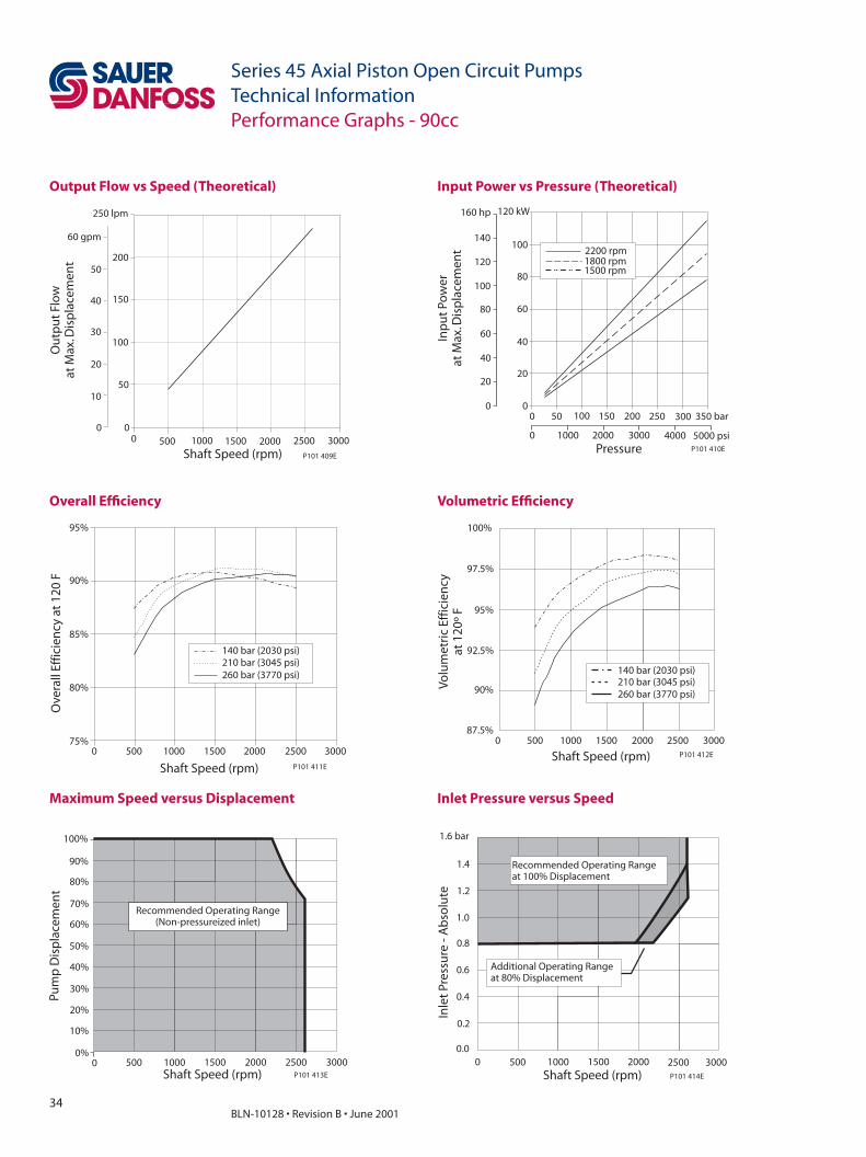
Series 45 Axial Piston Open Circuit PumpsTechnical InformationPerformance Graphs - 90cc
Output Flow vs Speed (Theoretical) Input Power vs Pressure (Theoretical)
Overall Effi ciency Volumetric Effi ciency
Maximum Speed versus Displacement Inlet Pressure versus Speed
Shaft Speed (rpm)
00 500 1000 1500 2000 2500 3000
0
1050
20
10030
40 150
50200
60 gpm
250 lpm
Ou
tpu
t Fl
ow
at M
ax.D
isp
lace
men
t
P101 409E
0 50 100 150 200 250 300 350 bar
Pressure0 1000 2000 3000 4000 5000 psi
00
20
40
60
80
100
120 kW
20
40
60
80
100
120
140
160 hp
Inp
ut
Pow
erat
Max
.Dis
pla
cem
ent
1500 rpm1800 rpm2200 rpm
P101 410E
P101 413E
0 500 1000 1500 2000 2500 3000Shaft Speed (rpm)
100%
90%
80%
70%
60%
50%
40%
30%
20%
10%
0%
Pum
pD
isp
lace
men
t
Recommended Operating Range(Non-pressureized inlet)
2500 30000.0
0.2
0.4
0.6
0.8
1.0
1.2
1.6 bar
Shaft Speed (rpm)
Inle
t Pr
essu
re -
Ab
solu
te
Additional Operating Rangeat 80% Displacement
Recommended Operating Rangeat 100% Displacement
0 500 1000 1500 2000P101 414E
1.4
140 bar (2030 psi)210 bar (3045 psi)260 bar (3770 psi)
Shaft Speed (rpm)
0 500 1000 1500 2000 2500 300075%
80%
85%
90%
95%
Ove
rall
Effic
ien
cy a
t 12
0 F
P101 411EShaft Speed (rpm)
Volu
met
ric
Effic
ien
cyat
120
º F
90%
92.5%
95%
97.5%
100%
0 500 1000 1500 2000 2500 3000
140 bar (2030 psi)210 bar (3045 psi)260 bar (3770 psi)
P101 412E
87.5%
35BLN-10128 • Revision B • June 2001
Series 45 Axial Piston Open Circuit PumpsTechnical Information
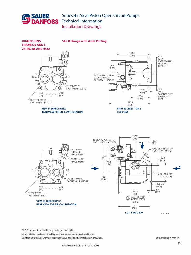
Dimensions in mm [in]
All SAE straight thread O-ring ports per SAE J514.
Shaft rotation is determined by viewing pump from input shaft end.
Contact your Sauer-Danfoss representative for specifi c installation drawings.
Installation Drawings
DIMENSIONSFRAMES K AND L25, 30, 38, AND 45cc
181.9[7.16]
70.4[2.77]
67.7[2.67]CASE DRAIN ‘L2’SPOTFACEDEPTH
223.2[8.79]
105.8[4.16]
67.7[2.67]CASE DRAIN ‘L1’SPOTFACEDEPTH
15.0[0.59]
SYSTEM PRESSUREGAGE PORT ‘M2’SAE J1926/1: .5625-18
INLET PORT ‘S’SAE J1926/1:1.875-12
33.0[1.3]
33.0[1.3]
OUTLET PORT ‘B’SAE J1926/1:1.3125-12
OUTLET PORT ‘B’SAE J1926/1:1.3125-12
33.0[1.3]
INLET PORT ‘S’SAE J1926/1:1.875-12
33.0[1.3]
PC PRESSUREADJUSTMENT
LS STANDBYPRESSUREADJUSTMENT
62[2.44]
155.2[6.1]
134.3[5.29]
175.1[6.89]
172.6[6.8]
SPOTFACE LOCATIONFOR SYSTEM PORTS
‘B’ & ‘S’
9.4[0.37]
R0.8 MAX[0.03]
37.0[1.46]
80.0[3.15]
CASE DRAIN PORT ‘L1’SAE J1926/1: .875-14
167.7[6.6]LS SIGNAL PORT ‘X’
SAE J1926/1: .4375-20
101.57 0.025[3.999 .001]
P101 415E
B
S
S
B
VIEW IN DIRECTION ZREAR VIEW FOR LH (CCW) ROTATION
VIEW IN DIRECTION YTOP VIEW
VIEW IN DIRECTION ZREAR VIEW FOR RH (CW) ROTATION
LEFT SIDE VIEW
SAE B Flange with Axial Porting
Z X
Y

36BLN-10128 • Revision B • June 2001
Series 45 Axial Piston Open Circuit PumpsTechnical Information
All SAE straight thread O-ring ports per SAE J514.
Shaft rotation is determined by viewing pump from input shaft end.
Contact your Sauer-Danfoss representative for specifi c installation drawings. Dimensions in mm [in]
Installation Drawings
80.0[3.15]
32.0[1.26]
25.8[1.02]
CASE DRAIN PORT ‘L2’SAE J1926/1: .875-14OR ISO 6149-1 :M22X1.5
APPROXIMATECENTER OFGRAVITY
181.9[7.16]
97.4[3.83]
146.0[5.75]
73.0[2.87]
APPROXIMATECENTER OFGRAVITY
6.7[0.26]
132.0[5.2]
121.9[4.8]
95.0[3.74]
LS SIGNALPORT ‘X’
16.4[0.65]
2X
P101 416EVIEW IN DIRECTION XFRONT VIEW
VIEW IN DIRECTION VRIGHT SIDE VIEW
DIMENSIONSFRAMES K AND L25, 30, 38, AND 45cc(continued)
SAE B Flange with Axial Porting (continued)
V
37BLN-10128 • Revision B • June 2001
Series 45 Axial Piston Open Circuit PumpsTechnical Information
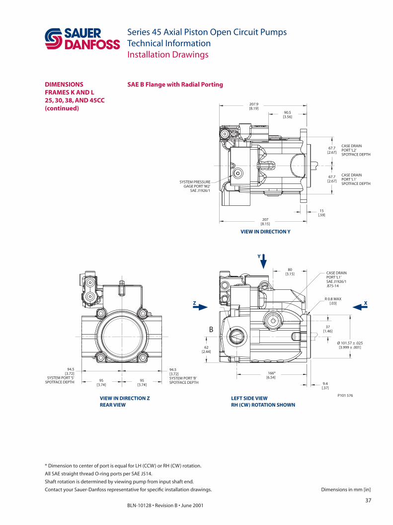
Dimensions in mm [in]
All SAE straight thread O-ring ports per SAE J514.
Shaft rotation is determined by viewing pump from input shaft end.
Contact your Sauer-Danfoss representative for specifi c installation drawings.
SYSTEM PRESSUREGAGE PORT ‘M2’
SAE J1926/1
67.7[2.67]
67.7[2.67]
CASE DRAINPORT ‘L2’SPOTFACE DEPTH
CASE DRAINPORT ‘L1’SPOTFACE DEPTH
90.5[3.56]
207.9[8.19]
207[8.15]
15[.59]
62[2.44]
166*[6.54]
9.4[.37]
Ø 101.57 ± .025[3.999 ± .001]
37[1.46]
R 0.8 MAX[.03]
CASE DRAINPORT ‘L1’SAE J1926/1.875-14
80[3.15]
95[3.74]
95[3.74]
94.5[3.72]
SYSTEM PORT ‘S’SPOTFACE DEPTH
94.5[3.72]SYSTEM PORT ‘B’SPOTFACE DEPTH
P101 576
B
Installation Drawings
DIMENSIONSFRAMES K AND L25, 30, 38, AND 45CC(continued)
SAE B Flange with Radial Porting
Z X
VIEW IN DIRECTION Y
Y
LEFT SIDE VIEWRH (CW) ROTATION SHOWN
VIEW IN DIRECTION ZREAR VIEW
* Dimension to center of port is equal for LH (CCW) or RH (CW) rotation.

38BLN-10128 • Revision B • June 2001
Series 45 Axial Piston Open Circuit PumpsTechnical Information
All SAE straight thread O-ring ports per SAE J514.
Shaft rotation is determined by viewing pump from input shaft end.
Contact your Sauer-Danfoss representative for specifi c installation drawings. Dimensions in mm [in]
99[3.9]
LS SIGNAL PORT ‘X’SPOTFACE DEPTH
LS STANDBYPRESSUREADJUSTMENT
PC PRESSUREADJUSTMENT
APPROXIMATECENTER OFGRAVITY
73[2.87]
146[5.75]
R 8.2[.32]2X
132[5.2]
121.9[4.8]
4.4[.17]
32[1.26]
134.3[5.29]
112.8[4.44]
146[5.75]
155.2[6.11]
APPROXIMATECENTER OFGRAVITY
20.7[.81]
80[3.15]
166*[6.54]
SYSTEMPORT ‘S’[INLET]SAE J1926/1
CASE DRAINPORT ‘L2’SAE J1926/1.875-14
P101 577
S
Installation Drawings
DIMENSIONSFRAMES K AND L25, 30, 38, AND 45CC(continued)
SAE B Flange with Radial Porting (continued)
VIEW IN DIRECTION XFRONT VIEW
VIEW IN DIRECTION VRIGHT SIDE VIEWRH (CW) ROTATION SHOWN
V
* Dimension to center of port is equal for LH (CCW) or RH (CW) rotation.
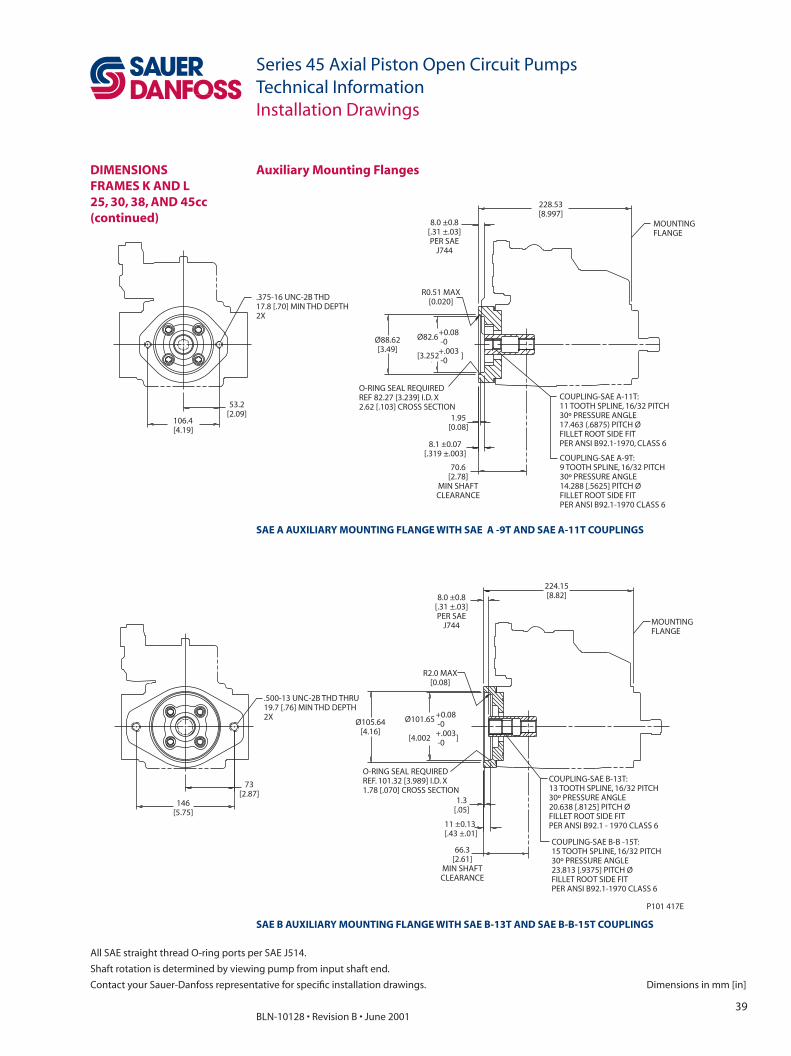
39BLN-10128 • Revision B • June 2001
Series 45 Axial Piston Open Circuit PumpsTechnical Information
Dimensions in mm [in]
All SAE straight thread O-ring ports per SAE J514.
Shaft rotation is determined by viewing pump from input shaft end.
Contact your Sauer-Danfoss representative for specifi c installation drawings.
Installation Drawings
DIMENSIONSFRAMES K AND L25, 30, 38, AND 45cc(continued)
SAE B AUXILIARY MOUNTING FLANGE WITH SAE B-13T AND SAE B-B-15T COUPLINGS
.375-16 UNC-2B THD17.8 [.70] MIN THD DEPTH2X
106.4[4.19]
53.2[2.09]
MOUNTINGFLANGE
70.6[2.78]
MIN SHAFTCLEARANCE
O-RING SEAL REQUIREDREF 82.27 [3.239] I.D. X2.62 [.103] CROSS SECTION
Ø82.6
[3.252 ]
+0.08-0+.003-0
COUPLING-SAE A-11T:11 TOOTH SPLINE, 16/32 PITCH30º PRESSURE ANGLE17.463 (.6875) PITCH ØFILLET ROOT SIDE FITPER ANSI B92.1-1970, CLASS 6
COUPLING-SAE A-9T:9 TOOTH SPLINE, 16/32 PITCH30º PRESSURE ANGLE14.288 [.5625] PITCH ØFILLET ROOT SIDE FITPER ANSI B92.1-1970 CLASS 6
228.53[8.997]
Ø88.62[3.49]
1.95[0.08]
R0.51 MAX[0.020]
73[2.87]
146[5.75]
.500-13 UNC-2B THD THRU19.7 [.76] MIN THD DEPTH2X
MOUNTINGFLANGE
224.15[8.82]
66.3[2.61]
MIN SHAFTCLEARANCE
11 ±0.13[.43 ±.01]
1.3[.05]
O-RING SEAL REQUIREDREF. 101.32 [3.989] I.D. X1.78 [.070] CROSS SECTION
Ø105.64[4.16]
Ø101.65
[4.002 ]
+0.08-0+.003-0
COUPLING-SAE B-B -15T:15 TOOTH SPLINE, 16/32 PITCH30º PRESSURE ANGLE23.813 [.9375] PITCH ØFILLET ROOT SIDE FITPER ANSI B92.1-1970 CLASS 6
COUPLING-SAE B-13T:13 TOOTH SPLINE, 16/32 PITCH30º PRESSURE ANGLE20.638 [.8125] PITCH ØFILLET ROOT SIDE FITPER ANSI B92.1 - 1970 CLASS 6
8.1 ±0.07[.319 ±.003]
8.0 ±0.8[.31 ±.03]PER SAE
J744
8.0 ±0.8[.31 ±.03]PER SAE
J744
R2.0 MAX[0.08]
P101 417E
SAE A AUXILIARY MOUNTING FLANGE WITH SAE A -9T AND SAE A-11T COUPLINGS
Auxiliary Mounting Flanges
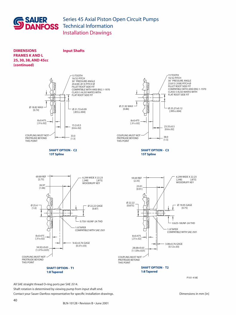
40BLN-10128 • Revision B • June 2001
Series 45 Axial Piston Open Circuit PumpsTechnical Information
All SAE straight thread O-ring ports per SAE J514.
Shaft rotation is determined by viewing pump from input shaft end.
Contact your Sauer-Danfoss representative for specifi c installation drawings. Dimensions in mm [in]
Installation Drawings
8 0.475[.31±.02]
±
COUPLING MUST NOTPROTRUDE BEYONDTHIS POINT
13 TOOTH16/32 PITCH30˚ PRESSURE ANGLE
FILLET ROOT SIDE FITCOMPATIBLE WITH ANSI B92.1-1970CLASS 5 ALSO MATES WITHFLAT ROOT SIDE FIT
20.638 [.813] PITCH Ø
Ø 18.82 MAX[0.74] Ø 21.72±0.09
[.855±.004]
15.2±0.5[0.6±.02]
33.0[1.3]
15 TOOTH16/32 PITCH30˚ PRESSURE ANGLE
FILLET ROOT SIDE FITCOMPATIBLE WITH ANSI B92.1-1970CLASS 5 ALSO MATES WITHFLAT ROOT SIDE FIT
23.813 [.938] PITCH Ø
Ø 25.27±0.12[.995±.004]
23.35±0.5[0.6±.02]
38.0[1.5]
COUPLING MUST NOTPROTRUDE BEYONDTHIS POINT
8 0.475[.31±.02]
±
Ø 21.92 MAX[0.86]
69.89 REF[2.75]
26.97[1.06]
Ø 25.4[1.0]
8 0.475[.31±.02]
±
COUPLING MUST NOTPROTRUDE BEYONDTHIS POINT
34.92±0.63[1.375±.025]
9.42±0.76 GAGE[0.37±.03]
Ø 22.22 GAGE[0.87]
1: 8 TAPERCOMPATIBLE WITH SAE J501
0.750-16UNF-2A THD
6.299 WIDE X 22.23[.248] [.875]WOODRUFF KEY
59.69 REF[2.35]
23.01[0.91]
Ø 19.05 GAGE[0.75]
0.625-18UNF-2A THD
1: 8 TAPERCOMPATIBLE WITH SAE J501
COUPLING MUST NOTPROTRUDE BEYONDTHIS POINT
3.08±0.76 GAGE[0.12±.03]
8 0.475[.31±.02]
±
28.68±0.63[1.129±.025]
Ø 22.22[0.875]
P101 418E
6.299 WIDE X 22.23[.248] [.875]WOODRUFF KEY
SHAFT OPTION - C213T Spline
SHAFT OPTION - C315T Spline
SHAFT OPTION - T11:8 Tapered
SHAFT OPTION - T21:8 Tapered
Input ShaftsDIMENSIONSFRAMES K AND L25, 30, 38, AND 45cc(continued)

41BLN-10128 • Revision B • June 2001
Series 45 Axial Piston Open Circuit PumpsTechnical Information
Dimensions in mm [in]
All SAE straight thread O-ring ports per SAE J514.
Shaft rotation is determined by viewing pump from input shaft end.
Contact your Sauer-Danfoss representative for specifi c installation drawings.
Installation Drawings
SAE C Flange with Axial Porting
B
40.4[1.59]
40.4[1.59]
INLET PORT “S”2.00-3000 PSISPLIT FLANGE BOSSPER SAE J518(CODE 61)
OUTLET PORT “B”1.00-3000 PSISPLIT FLANGE BOSSPER SAE J518(CODE 61)EXCEPT 18.6 [.73]MIN. FULL THD.
BS
SERVO PRESSURE GAGE PORT “M4”SAE J1926/1: .4375 - 20
LS STANDBYPRESSURE ADJUSTMENT(LOAD SENSINGCONTROLS ONLY)
67.0 [2.64]LS SIGNAL PORT “X”
PC CARTRIDGE VALVE(PC PRESSURE ADJUSTMENT)
REMOTE PRESSURE COMPENSATOR PORT
72.0[2.83]
144.0[5.67]
63.0[2.48]CASE DRAINPORT “L2”
LS SINGNAL PORT “X”(PLUGGED FOR PC CONTROL)SAE J1926/1: .4375 - 20
210.5[8.29]
115.7[4.56]
R0.8[0.03]
126.975 ±0.025[4.999 ±0.001]
CASE DRAIN PORT “L1”SAE J1926/1: .875 - 14
215[8.46]
86.8[3.42]
73.0[2.87]
95 [3.7]TO C.G.
108[4.25]
X
L1
P101 084E
S
INLET PORT “S”2.00-3000 PSISPLIT FLANGE BOSSPER SAE J518(CODE 61)
OUTLET PORT “B”1.00-3000 PSISPLIT FLANGE BOSSPER SAE J518(CODE 61)EXCEPT 18.6 [.73]MIN. FULL THD.
40.4[1.59]
40.4[1.59]
DIMENSIONSFRAME H57 AND 75cc
VIEW IN DIRECTION ZREAR VIEW FOR LH (CCW) ROTATION
VIEW IN DIRECTION YTOP VIEW
VIEW IN DIRECTION ZREAR VIEW FOR RH (CW) ROTATION
LEFT SIDE VIEW
Z X
Y
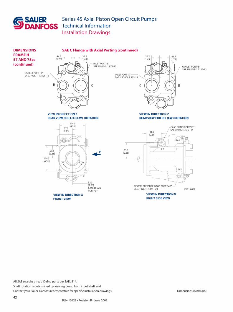
42BLN-10128 • Revision B • June 2001
Series 45 Axial Piston Open Circuit PumpsTechnical Information
All SAE straight thread O-ring ports per SAE J514.
Shaft rotation is determined by viewing pump from input shaft end.
Contact your Sauer-Danfoss representative for specifi c installation drawings. Dimensions in mm [in]
Installation Drawings
52.3[2.06]CASE DRAINPORT “L1”
114.5[4.51]
57.3[2.25]
57.3[2.25]
114.5[4.51]
CW CCW
CASE DRAIN PORT “L2”SAE J1926/1: .875 - 14
68.0[2.68]
73.0[2.88]
SYSTEM PRESSURE GAGE PORT “M2”SAE J1926/1: .4374 - 20
M4
L2
M2
OUTLET PORT “B”SAE J1926/1: 1.3125-12
INLET PORT “S”SAE J1926/1: 1.875-12
44.5[1.75]
36.2[1.43]
P101 085E
S B
44.5[1.75]
36.2[1.43]
INLET PORT “S”SAE J1926/1: 1.875-12
OUTLET PORT“B”SAE J1926/1: 1.3125-12
SB
VIEW IN DIRECTION ZREAR VIEW FOR LH (CCW) ROTATION
VIEW IN DIRECTION ZREAR VIEW FOR RH (CW) ROTATION
VIEW IN DIRECTION XFRONT VIEW
VIEW IN DIRECTION VRIGHT SIDE VIEW
DIMENSIONSFRAME H57 AND 75cc(continued)
SAE C Flange with Axial Porting (continued)
V
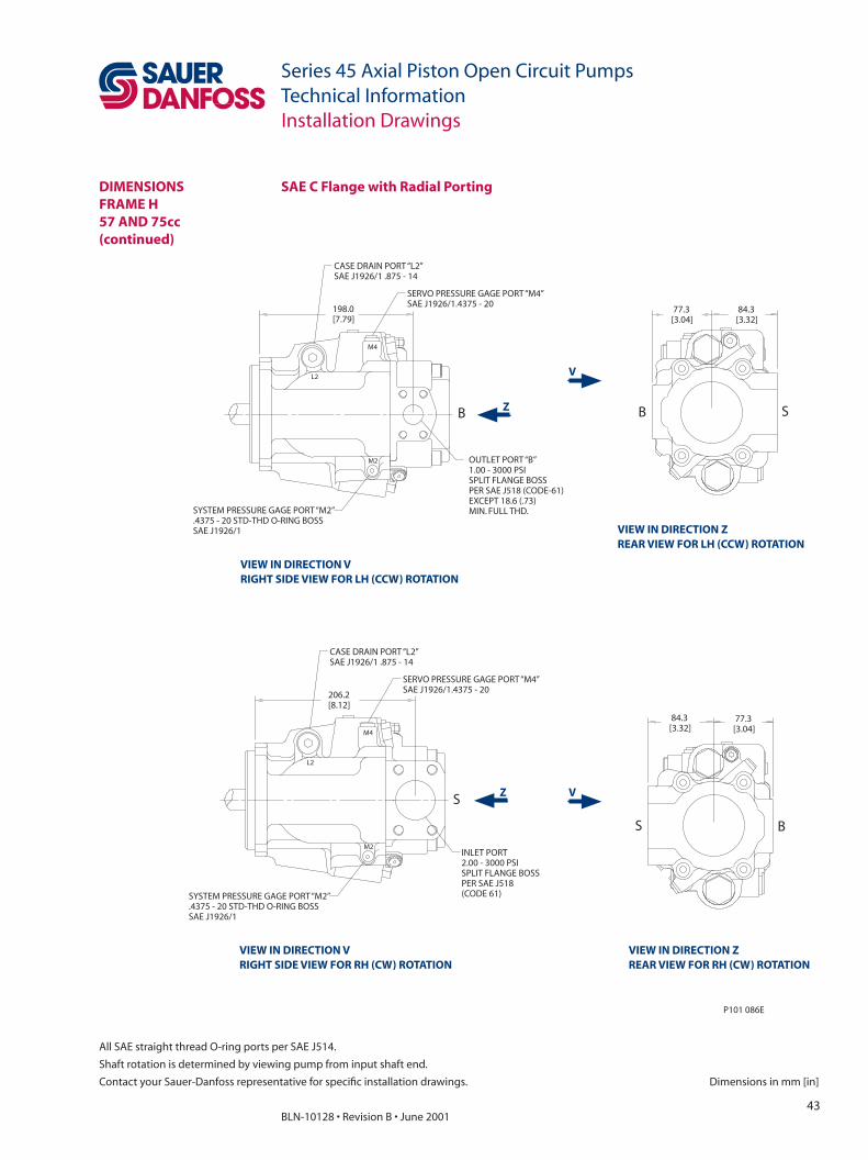
43BLN-10128 • Revision B • June 2001
Series 45 Axial Piston Open Circuit PumpsTechnical Information
Dimensions in mm [in]
All SAE straight thread O-ring ports per SAE J514.
Shaft rotation is determined by viewing pump from input shaft end.
Contact your Sauer-Danfoss representative for specifi c installation drawings.
Installation Drawings
SAE C Flange with Radial Porting
206.2[8.12]
77.3[3.04]
84.3[3.32]
B
84.3[3.32]
77.3[3.04]
P101 086E
S
BSM2
INLET PORT2.00 - 3000 PSISPLIT FLANGE BOSSPER SAE J518(CODE 61)
S
M4
L2
SYSTEM PRESSURE GAGE PORT “M2”.4375 - 20 STD-THD O-RING BOSSSAE J1926/1
SERVO PRESSURE GAGE PORT “M4”SAE J1926/1.4375 - 20
CASE DRAIN PORT “L2”SAE J1926/1 .875 - 14
SERVO PRESSURE GAGE PORT “M4”SAE J1926/1.4375 - 20
OUTLET PORT “B”1.00 - 3000 PSISPLIT FLANGE BOSSPER SAE J518 (CODE-61)EXCEPT 18.6 (.73)MIN. FULL THD.
B
198.0[7.79]
M2
M4
L2
SYSTEM PRESSURE GAGE PORT “M2”.4375 - 20 STD-THD O-RING BOSSSAE J1926/1
CASE DRAIN PORT “L2”SAE J1926/1 .875 - 14
VIEW IN DIRECTION VRIGHT SIDE VIEW FOR LH (CCW) ROTATION
VIEW IN DIRECTION ZREAR VIEW FOR LH (CCW) ROTATION
VIEW IN DIRECTION VRIGHT SIDE VIEW FOR RH (CW) ROTATION
VIEW IN DIRECTION ZREAR VIEW FOR RH (CW) ROTATION
DIMENSIONSFRAME H 57 AND 75cc(continued)
V
V
Z
Z

44BLN-10128 • Revision B • June 2001
Series 45 Axial Piston Open Circuit PumpsTechnical Information
All SAE straight thread O-ring ports per SAE J514.
Shaft rotation is determined by viewing pump from input shaft end.
Contact your Sauer-Danfoss representative for specifi c installation drawings. Dimensions in mm [in]
Installation Drawings
INLET PORT2.00-3000 PSISPLIT FLANGE BOSSPER SAE J518(CODE 61)
206.2[8.12]
244.5[9.63]
198.0[7.79]
X
L1OUTLET PORT “B”1.00 - 5000 PSISPLIT FLANGE BOSSPER SAE J518 (CODE 61)EXCEPT 18.6 [.73]MIN. FULL THD.
P101087E
CASE DRAIN PORT “L1”SAE J1926/1: .875-14
LS SIGNAL PORT “X”SAE J1926/1: .4375-20
244.5[9.63]
X
L1
CASE DRAIN PORT “L1”SAE J1926/1: .875-14
LS SIGNAL PORT “X”SAE J1926/1: .4375-20
S
B
LEFT SIDE VIEW FOR LH (CCW) ROTATION
LEFT SIDE VIEW FOR RH (CW) ROTATION
SAE C Flange with Radial Porting (continued)DIMENSIONSFRAME H57 AND 75cc(continued)

45BLN-10128 • Revision B • June 2001
Series 45 Axial Piston Open Circuit PumpsTechnical Information
Dimensions in mm [in]
All SAE straight thread O-ring ports per SAE J514.
Shaft rotation is determined by viewing pump from input shaft end.
Contact your Sauer-Danfoss representative for specifi c installation drawings.
Installation Drawings
SAE B Flange with Axial Porting
SERVO PRESSURE GAGE PORT “M4”SAE J1926/1 .4375-20
LS STANDBYPRESSURE ADJUSTMENT
67.0[2.64]
63.0[2.48]
18.0[0.71]
148.2[5.83]
REMOTE PC PORT
PC PRESSUREADJUSTMENTS
36.2[1.43]
44.5[1.75]
INLET PORT “S”2.00 - 3000 PSISPLIT FLANGE BOSSPER SAE J518(CODE 61)
OUTLET PORT “B”1.00-5000 PSI)SPLIT FLANGE BOSSPER SAE J518 (CODE 61)EXCEPT 18.6 [0.73]MIN. FULL THD.
125[4.9]
TO C.G.9.7
[0.38]138.0[5.43]
R0.8 MAX[0.03]
Ø101.575±0.025[3.999±.001]
LS SIGNAL PORT “X”(PLUGGED FOR PC CONTROL)
SAE J1926/1 .4375-20240.5[9.47]
15.8[0.62]
4X
145.7[5.74]
215[8.46]
106.8[4.20]
86.8[3.42]
73.0[2.87]
CASE DRAIN PORT “L1”SAE J1926/1:0.875-14
P101 107E
SB
S B
INLET PORT “S”2.00 - 3000 PSISPLIT FLANGE BOSSPER SAE J518(CODE 61)
OUTLET PORT “B”1.00-5000 PSI)SPLIT FLANGE BOSSPER SAE J518 (CODE 61)EXCEPT 18.6 [0.73]MIN. FULL THD.
36.2[1.43]
44.5[1.75]
144.0[5.67]
VIEW IN DIRECTION ZREAR VIEW FOR LH ROTATION VIEW IN DIRECTION Y
TOP VIEW
VIEW IN DIRECTION ZREAR VIEW FROM RH ROTATION
LEFT SIDE VIEW
DIMENSIONSFRAME H57 AND 75cc(continued)
Z
X
Y
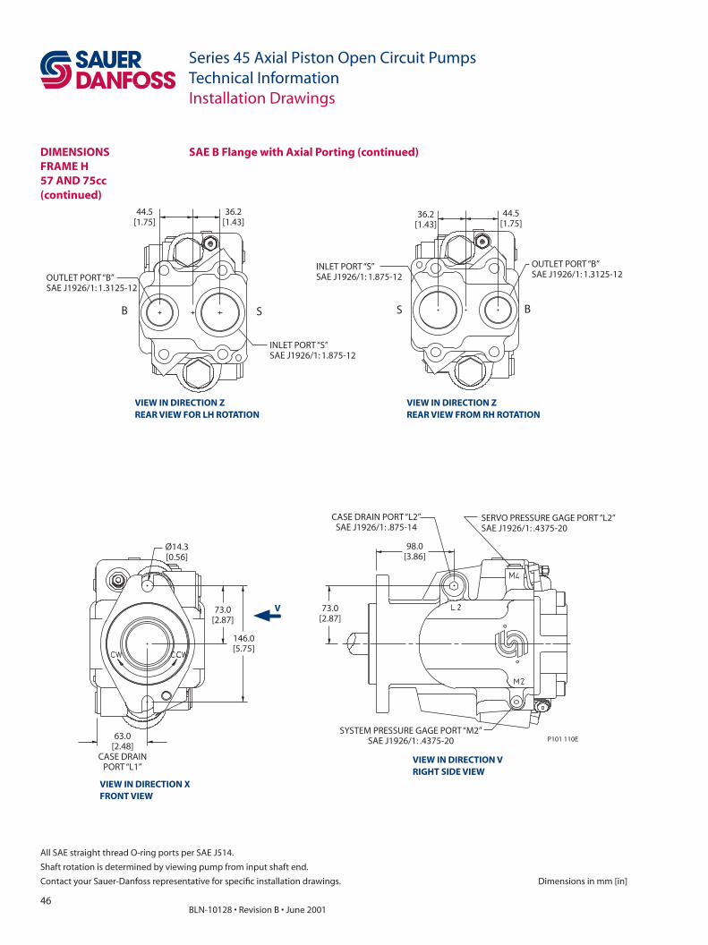
46BLN-10128 • Revision B • June 2001
Series 45 Axial Piston Open Circuit PumpsTechnical Information
All SAE straight thread O-ring ports per SAE J514.
Shaft rotation is determined by viewing pump from input shaft end.
Contact your Sauer-Danfoss representative for specifi c installation drawings. Dimensions in mm [in]
Installation Drawings
INLET PORT “S”SAE J1926/1: 1.875-12
OUTLET PORT “B”SAE J1926/1: 1.3125-12
Ø14.3[0.56]
73.0[2.87]
146.0[5.75]
63.0[2.48]
CASE DRAINPORT “L1”
SYSTEM PRESSURE GAGE PORT “M2”SAE J1926/1: .4375-20
73.0[2.87]
98.0[3.86]
CASE DRAIN PORT “L2”SAE J1926/1: .875-14
44.5[1.75]
36.2[1.43]
P101 110E
B S BS
44.5[1.75]
36.2[1.43]
INLET PORT “S”SAE J1926/1: 1.875-12
OUTLET PORT “B”SAE J1926/1: 1.3125-12
SERVO PRESSURE GAGE PORT “L2”SAE J1926/1: .4375-20
VIEW IN DIRECTION ZREAR VIEW FOR LH ROTATION
VIEW IN DIRECTION ZREAR VIEW FROM RH ROTATION
VIEW IN DIRECTION XFRONT VIEW
VIEW IN DIRECTION VRIGHT SIDE VIEW
SAE B Flange with Axial Porting (continued)DIMENSIONSFRAME H57 AND 75cc(continued)
V
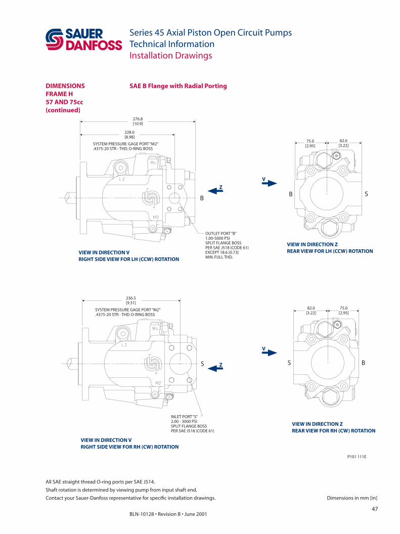
47BLN-10128 • Revision B • June 2001
Series 45 Axial Piston Open Circuit PumpsTechnical Information
Dimensions in mm [in]
All SAE straight thread O-ring ports per SAE J514.
Shaft rotation is determined by viewing pump from input shaft end.
Contact your Sauer-Danfoss representative for specifi c installation drawings.
Installation Drawings
SAE B Flange with Radial Porting
82.0[3.22]
75.0[2.95]
OUTLET PORT “B”1.00-5000 PSISPLIT FLANGE BOSSPER SAE J518 (CODE 61)EXCEPT 18.6 [0.73]MIN. FULL THD.
228.0[8.98]
276.8[10.9]
SYSTEM PRESSURE GAGE PORT “M2”.4375-20 STR - THD. O-RING BOSS
236.5[9.31]
INLET PORT “S”2.00 - 3000 PSISPLIT FLANGE BOSSPER SAE J518 (CODE 61)
P101 111E
B S
S S B
82.0[3.22]
75.0[2.95]SYSTEM PRESSURE GAGE PORT “M2”
.4375-20 STR - THD. O-RING BOSS
B
VIEW IN DIRECTION VRIGHT SIDE VIEW FOR LH (CCW) ROTATION
VIEW IN DIRECTION ZREAR VIEW FOR LH (CCW) ROTATION
VIEW IN DIRECTION VRIGHT SIDE VIEW FOR RH (CW) ROTATION
VIEW IN DIRECTION ZREAR VIEW FOR RH (CW) ROTATION
DIMENSIONSFRAME H57 AND 75cc(continued)
V
V
Z
Z
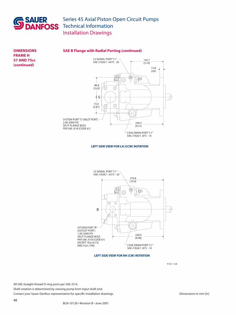
48BLN-10128 • Revision B • June 2001
Series 45 Axial Piston Open Circuit PumpsTechnical Information
All SAE straight thread O-ring ports per SAE J514.
Shaft rotation is determined by viewing pump from input shaft end.
Contact your Sauer-Danfoss representative for specifi c installation drawings. Dimensions in mm [in]
Installation Drawings
228.0[8.98]
276.8[10.9]
SYSTEM PORT “B”(OUTLET PORT)1.00-5000 PSISPLIT FLANGE BOSSPER SAE J518 (CODE 61)EXCEPT 18.6 [0.73]MIN. FULL THD.
236.5[9.31]
SYSTEM PORT “S” (INLET PORT)2.00-3000 PSISPLIT FLANGE BOSSPER SAE J518 [CODE 61]
P101 112E
B
CASE DRAIN PORT “L1”SAE J1926/1 .875 - 14
LS SIGNAL PORT “L1”SAE J1926/1 .4375 - 20
CASE DRAIN PORT “L1”SAE J1926/1 .875 - 14
LS SIGNAL PORT “L1”SAE J1926/1 .4375 - 20
S
145.7[5.74]
15.8[.62]
86.8[3.42]
73.0[2.87]
LEFT SIDE VIEW FOR LH (CCW) ROTATION
LEFT SIDE VIEW FOR RH (CW) ROTATION
SAE B Flange with Radial Porting (continued)DIMENSIONSFRAME H57 AND 75cc(continued)
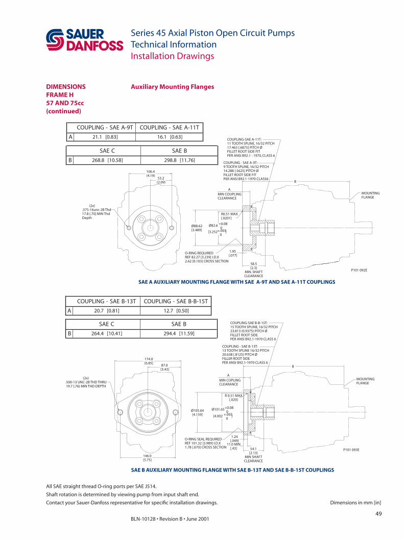
49BLN-10128 • Revision B • June 2001
Series 45 Axial Piston Open Circuit PumpsTechnical Information
Dimensions in mm [in]
All SAE straight thread O-ring ports per SAE J514.
Shaft rotation is determined by viewing pump from input shaft end.
Contact your Sauer-Danfoss representative for specifi c installation drawings.
Installation Drawings
Auxiliary Mounting Flanges
SAE A AUXILIARY MOUNTING FLANGE WITH SAE A-9T AND SAE A-11T COUPLINGS
SAE B AUXILIARY MOUNTING FLANGE WITH SAE B-13T AND SAE B-B-15T COUPLINGS
(2x).375-16unc-2B Thd17.8 [.70] MIN ThdDepth
1.95[.077]
58.5[2.3]
MIN. SHAFTCLEARANCE
O-RING REQUIREDREF 82.27 [3.239] I.D.X2.62 [0.103] CROSS SECTION
Ø88.62[3.489]
R0.51 MAX[.0201]
Ø82.6 +0.080
[3.252 ]+.0030
AMIN COUPLINGCLEARANCE
MOUNTINGFLANGE
B
COUPLING - SAE A-9T:9 TOOTH SPLINE, 16/32 PITCH14.288 [.5625] PITCH ØFILLET ROOT SIDE FITPER ANSI B92.1-1970 CLASS6
COUPLING-SAE A-11T:11 TOOTH SPLINE, 16/32 PITCH17.463 [.6875] PITCH ØFILLET ROOT SIDE FITPER ANSI B92.1 - 1970, CLASS 6
106.4(4.19)
53.2(2.09)
P101 092E
(2x).500-13 UNC-2B THD THRU19.7 [.76] MIN THD DEPTH
146.0[5.75]
174.0[6.85]
87.0[3.43]
MOUNTINGFLANGE
B
COUPLING - SAE B-13T:13 TOOTH SPLINE 16/32 PITCH20.638 [.8125] PITCH ØFILLER ROOT SIDEPER ANSI B92.1-1970 CLASS 6
COUPLING-SAE B-B-15T:15 TOOTH SPLINE, 16/32 PITCH23.813 (0.9375) PITCH ØFILLET ROOT SIDEPER ANSI B92.1-1970 CLASS 6
54.1[2.13]
MIN SHAFTCLEARANCE
O-RING SEAL REQUIREDREF 101.32 [3.989] I.D.X1.78 [.070] CROSS SECTION
1.24[.049]
11.0 MIN[.43]
AMIN COPLINGCLEARANCE
R 0.51 MAX[.020]
Ø105.64[4.159]
Ø101.65+0.080
[4.002 ]+.0030
P101 093E
T9-AEAS-GNILPUOC T11-AEAS-GNILPUOC
A ]38.0[1.12 ]36.0[1.61
CEAS BEAS
B ]85.01[8.862 ]67.11[8.892
T31-BEAS-GNILPUOC T51-B-BEAS-GNILPUOC
A ]18.0[7.02 ]05.0[7.21
CEAS BEAS
B ]14.01[4.462 ]95.11[4.492
DIMENSIONSFRAME H57 AND 75cc(continued)

50BLN-10128 • Revision B • June 2001
Series 45 Axial Piston Open Circuit PumpsTechnical Information
All SAE straight thread O-ring ports per SAE J514.
Shaft rotation is determined by viewing pump from input shaft end.
Contact your Sauer-Danfoss representative for specifi c installation drawings. Dimensions in mm [in]
Installation Drawings
SAE C AUXILIARY MOUNTING FLANGE WITH SAE C-14T COUPLING
(4x).500-13 UNC - 2B THD THRU22.7 [.89] MIN THD DEPTH
146.5[5.77]
73.3[2.88]
57.3[2.25]
114.5[4.51]
57.2[2.25]
114.5[4.51]
57.1[2.25]
MIN SHAFTCLEARANCE
1.3[.05]
13.8 MIN[.54]
O-RING SEAL REQUIREDREF 120.37 [4.379] I.D. X1.78 [.070] CROSS SECTION
Ø131.57[5.18]
Ø129.03
[5.001 ]
+0.050
+.0020
R0.51 MAX[.020]
9.0[.35]MIN COUPLINGCLEARANCE MOUNTING
FLANGE
B
COUPLING - SAE C-14T:14 TOOTH SPLINE, 12/24 PITCH29.633 [1.1667] PITCH ØFLAT ROOT SIDE FITPER ANSI B92.1-1970 CLASS 6
P101 094E
CEAS BEAS
B ]14.01[4.462 ]95.11[4.492
Auxiliary Mounting Flanges (continued)DIMENSIONSFRAME H57 AND 75cc(continued)

51BLN-10128 • Revision B • June 2001
Series 45 Axial Piston Open Circuit PumpsTechnical Information
Dimensions in mm [in]
All SAE straight thread O-ring ports per SAE J514.
Shaft rotation is determined by viewing pump from input shaft end.
Contact your Sauer-Danfoss representative for specifi c installation drawings.
Installation Drawings
Input Shafts
8±0.8[.31±.03]
COUPLING MUST NOTPROTRUDE BEYONDTHIS POINT
SPLINED SHAFT29.63 [1.17] PITCH Ø14 TEETH, 12/24 PITCH30˚ PRESSURE ANGLEFILLET ROOT SIDE FITCOMPATIBLE WITH ANSI B92.1-1970CLASS 5 ALSO MATES WITHFLAT ROOT SIDE FIT
8+0.8[.31±.03]
COUPLING MUST NOTPROTRUDE BEYONDTHIS POINT
SPLINED SHAFT20.638 [.813] PITCH Ø13 TEETH, 16/32 PITCH30˚ PRESSURE ANGLEFILLET ROOT SIDE FITCOMPATIBLE WITH ANSI B92.1-1970CLASS 5 ALSO MATES WITHFLAT ROOT SIDE FIT
8±0.8[.31±.03]
COUPLING MUST NOTPROTRUDE BEYONDTHIS POINT
SPLINED SHAFT23.813 [.938] PITCH Ø15 TEETH, 16/32 PITCH30˚ PRESSURE ANGLEFILLET ROOT SIDE FITCOMPATIBLE WITH ANSI B92.1-1970CLASS 5 ALSO MATES WITHFLAT ROOT SIDE FIT
16.7[.66]
33.3[1.31]
18.5[.73]
22.13[.871]
30.0[1.18]
47.6[1.87]
27.6[1.09]
31.14[1.23]
22.36[.88]
28.0[1.5]
21.84[.86]
25.34[.998]
P101 098E
SHAFT OPTION - S114T Spline
SHAFT OPTION - C2/D213T Spline
SHAFT OPTION - C3/D315T Spline
DIMENSIONSFRAME H57 AND 75cc(continued)

52BLN-10128 • Revision B • June 2001
Series 45 Axial Piston Open Circuit PumpsTechnical Information
All SAE straight thread O-ring ports per SAE J514.
Shaft rotation is determined by viewing pump from input shaft end.
Contact your Sauer-Danfoss representative for specifi c installation drawings. Dimensions in mm [in]
Installation Drawings
8±0.8[.31±.03]
COUPLING MUST NOTPROTRUDE BEYONDTHIS POINT
1.0 OD - 20 UNEF - 2A THD1 - 20 UNEF - 2A
62 REF[2.44]
8±0.8[.31±.03]
COUPLING MUST NOTPROTRUDE BEYONDTHIS POINT
56 REF[2.2]
42.9[1.69]
22.4[0.88]GAGE DIA.
30.2 GAGE DIA.[1.19]
47.6[1.87]
31.72[1.249]
P101 099E
7.94 SQ KEY X 28.56 LONG[.313] [1.125]
7.94 WIDE X 31.8[0.3105] [1.25]WOODRUFF KEY
1: 8 TAPER COMPATIBLEWITH SAE J50131.8 [1.25] NOMINAL SHAFT DIA.
SHAFT OPTION - TO1:8 Tapered
SHAFT OPTION - K4/L4Straight Keyed
Input Shafts (continued)DIMENSIONSFRAME H57 AND 75cc(continued)

53BLN-10128 • Revision B • June 2001
Series 45 Axial Piston Open Circuit PumpsTechnical Information
Dimensions in mm [in]
All SAE straight thread O-ring ports per SAE J514.
Shaft rotation is determined by viewing pump from input shaft end.
Contact your Sauer-Danfoss representative for specifi c installation drawings.
Installation Drawings
DIMENSIONSFRAME G74 AND 90cc
LS SIGNALPORT “X”
60.7[2.39]
21.3[0.84]
LS SIGNALPORT “X”ALTERNATE
40.0[1.57] 45
[1.77]
INLET PORT “S”2.00-3000 PSISPLIT FLANGE BOSSPER SAE J518(CODE 61)
OUTLET PORT “B”1.00-5000 PSISPLIT FLANGE BOSSPER SAE J518(CODE 61)
LS SIGNAL PORT “X”(PLUGGED FOR PC CONTROL)SAE J1926/1: .4375-20 227.74
[8.97]
102.84[4.05]
126.975 ±0.025[4.999 ±0.001]
110.0[4.33]
SYSTEM PRESSURE GAGE PORT “M2”SAE J1926/1: .4375-20
121.76[4.79]
265.76[10.46]
128.5[5.06]
B S
S B
LS SIGNALPORT “X”
60.7[2.39]
21.3[0.84]
LS SIGNALPORT “X”ALTERNATE
40.0[1.57]45
[1.77]
INLET PORT “S”2.00-3000 PSISPLIT FLANGE BOSSPER SAE J518(CODE 61)
OUTLET PORT “B”1.00-5000 PSISPLIT FLANGE BOSSPER SAE J518(CODE 61)
CASE DRAIN PORT “L2”SAE J1926/1: .875-14
73[2.87]
151[5.94]
CASE DRAIN PORT “L1”SAE J1926/1: .875-14
45[1.77]
72.74[2.86]
VIEW IN DIRECTION ZREAR VIEW FOR LH (CCW) ROTATION
VIEW IN DIRECTION YTOP VIEW
VIEW IN DIRECTION ZREAR VIEW FOR RH (CW) ROTATION
LEFT SIDE VIEW
SAE C Flange with Axial Porting
Z
X
Y

54BLN-10128 • Revision B • June 2001
Series 45 Axial Piston Open Circuit PumpsTechnical Information
All SAE straight thread O-ring ports per SAE J514.
Shaft rotation is determined by viewing pump from input shaft end.
Contact your Sauer-Danfoss representative for specifi c installation drawings. Dimensions in mm [in]
SAE C Flange with Axial Porting (continued)
Installation Drawings
VIEW IN DIRECTION XFRONT VIEW
VIEW IN DIRECTION VRIGHT SIDE VIEW
PC PRESSUREADJUSTMENT
LS STANDBYPRESSURE ADJUSTMENT
14.3[0.56]
57.25[2.25]
114.5[4.51]
CW CCW
57.28[2.25]
114.5[4.51]
128.5[5.06]
102.84[4.05]
LS SIGNAL PORT “X”ALTERNATESAE J1926/1: .4375-20
SERVO PRESSURE GAGE PORT “M4SAE 1926/1: .4375-20
P101 089E
CASE DRAIN PORT “L1”SAE J1926/1:.875-14
72.64[2.86]
DIMENSIONSFRAME G74 AND 90cc(continued)
V
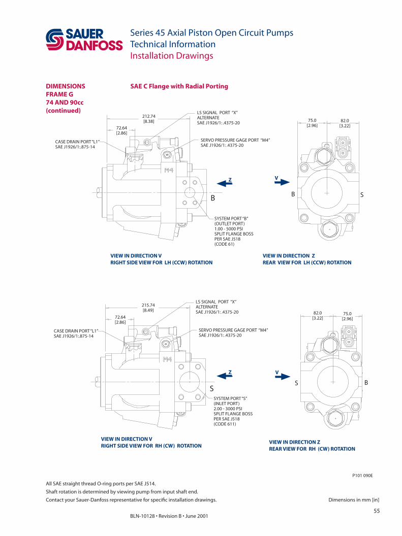
55BLN-10128 • Revision B • June 2001
Series 45 Axial Piston Open Circuit PumpsTechnical Information
Dimensions in mm [in]
All SAE straight thread O-ring ports per SAE J514.
Shaft rotation is determined by viewing pump from input shaft end.
Contact your Sauer-Danfoss representative for specifi c installation drawings.
Installation Drawings
SAE C Flange with Radial Porting
SYSTEM PORT “B”(OUTLET PORT)1.00 - 5000 PSISPLIT FLANGE BOSSPER SAE J518(CODE 61)
75.0[2.96]
82.0[3.22]
215.74[8.49]
SYSTEM PORT “S”(INLET PORT)2.00 - 3000 PSISPLIT FLANGE BOSSPER SAE J518(CODE 611)
82.0[3.22]
75.0[2.96]
P101 090E
B S
S B
CASE DRAIN PORT “L1”SAE J1926/1:.875-14
72.64[2.86]
CASE DRAIN PORT “L1”SAE J1926/1:.875-14
72.64[2.86]
212.74[8.38]
SERVO PRESSURE GAGE PORT “M4”SAE J1926/1: .4375-20
SERVO PRESSURE GAGE PORT “M4”SAE J1926/1: .4375-20
LS SIGNAL PORT “X”ALTERNATESAE J1926/1: .4375-20
LS SIGNAL PORT “X”ALTERNATESAE J1926/1: .4375-20
B
S
VIEW IN DIRECTION VRIGHT SIDE VIEW FOR LH (CCW) ROTATION
VIEW IN DIRECTION ZREAR VIEW FOR LH (CCW) ROTATION
VIEW IN DIRECTION VRIGHT SIDE VIEW FOR RH (CW) ROTATION
VIEW IN DIRECTION ZREAR VIEW FOR RH (CW) ROTATION
DIMENSIONSFRAME G74 AND 90cc(continued)
V
VZ
Z

56BLN-10128 • Revision B • June 2001
Series 45 Axial Piston Open Circuit PumpsTechnical Information
All SAE straight thread O-ring ports per SAE J514.
Shaft rotation is determined by viewing pump from input shaft end.
Contact your Sauer-Danfoss representative for specifi c installation drawings. Dimensions in mm [in]
Installation Drawings
256.04[10.08]
212.74[8.38]
OUTLET PORT “B”1.00 - 5000 PSISPLIT FLANGE BOSSPER SAE J518(CODE 61)
P101 091E
B
215.74[8.49]
INLET PORT “S”2.00 - 3000 PSISPLIT FLANGE BOSSPER SAE J518(CODE 61)
S
256.04[10.08]
LS SIGNAL PORT “X”SAE J1926/1: .4375-20
LS SIGNAL PORT “X”SAE J1926/1: .4375-20
SYSTEM PRESSURE GAGE PORT “M2”SAE J1926/1: .4375-20
SYSTEM PRESSURE GAGE PORT “M2”SAE J1926/1: .4375-20
LEFT SIDE VIEW FOR LH (CCW) ROTATION
LEFT SIDE VIEW FOR RH (CW) ROTATION
SAE C Flange with Radial Porting (continued)DIMENSIONSFRAME G74 AND 90cc(continued)
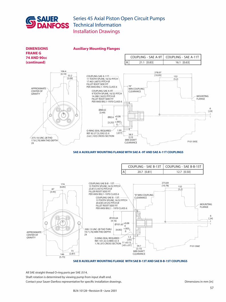
57BLN-10128 • Revision B • June 2001
Series 45 Axial Piston Open Circuit PumpsTechnical Information
Dimensions in mm [in]
All SAE straight thread O-ring ports per SAE J514.
Shaft rotation is determined by viewing pump from input shaft end.
Contact your Sauer-Danfoss representative for specifi c installation drawings.
Installation Drawings
Auxiliary Mounting Flanges
SAE A AUXILIARY MOUNTING FLANGE WITH SAE A -9T AND SAE A-11T COUPLINGS
APPROXIMATECENTER OFGRAVITY
.375-16 UNC-2B THD17.8 [.70] MIN THD DEPTH2X
106.4[4.19]
53.2[2.09]
6[.24]
MOUNTINGFLANGE
278.07[10.95] 132
[5.2]
58.5[2.3]
MIN SHAFTCLEARANCE
“A”MIN COUPLINGCLEARANCE
O-RING SEAL REQUIREDREF 82.27 [3.239] I.D. X2.62 [.103] CROSS SECTION
1.95[.077]
Ø88.62[3.49]
Ø82.6
[3.252 ]
+0.080
+.0030
COUPLING-SAE A-11T:11 TOOTH SPLINE, 16/32 PITCH17.463 (.6875) PITCH ØFILLET ROOT SIDE FITPER ANSI B92.1-1970, CLASS 6
COUPLING-SAE A-9T:9 TOOTH SPLINE, 16/32 PITCH14.288 [.5625] PITCH ØFILLET ROOT SIDE FITPER ANSI B92.1-1970 CLASS 6
P101 095E
174[6.85]
87[3.43]
73[2.87]146
[5.75]
APPROXIMATECENTER OFGRAVITY
.500-13 UNC-2B THD THRU19.7 [.76] MIN THD DEPTH2X
6[.24]
MOUNTINGFLANGE
273.69[10.78] 132
[5.2]
54.1[2.13]
MIN SHAFTCLEARANCE
“A” MIN COUPLINGCLEARANCE
11 ±0.13[.43 ±.01]
1.3[.05]
O-RING SEAL REQUIREDREF. 101.32 [3.989] I.D. X1.78 [.07] CROSS SECTION
Ø105.64[4.16]
Ø101.65
[4.002 ]
+0.080
+.0030
COUPLING-SAE B-B - 15T:15 TOOTH SPLINE, 16/32 PITCH23.813 [.9375] PITCH ØFILLER ROOT SIDE FITPER ANSI B92.1-1970 CLASS 6
COUPLING-SAE B - 13T:13 TOOTH SPLINE, 16/32 PITCH20.638 [.8125] PITCH ØFILLET ROOT SIDE FITPER ANSI B92.1 - 1970 CLASS 6
P101 096E
SAE B AUXILIARY MOUNTING FLANGE WITH SAE B-13T AND SAE B-B-15T COUPLINGS
T9-AEAS-GNILPUOC T11-AEAS-GNILPUOC
A ]38.0[1.12 ]36.0[1.61
T31-BEAS-GNILPUOC T51-B-BEAS-GNILPUOC
A ]18.0[7.02 ]05.0[7.21
DIMENSIONSFRAME G74 AND 90cc(continued)
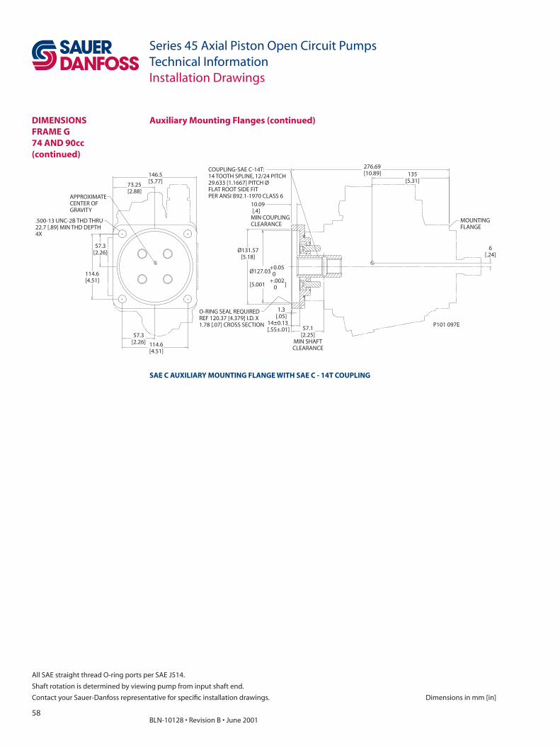
58BLN-10128 • Revision B • June 2001
Series 45 Axial Piston Open Circuit PumpsTechnical Information
All SAE straight thread O-ring ports per SAE J514.
Shaft rotation is determined by viewing pump from input shaft end.
Contact your Sauer-Danfoss representative for specifi c installation drawings. Dimensions in mm [in]
Installation Drawings
114.6[4.51]
57.3[2.26]
114.6[4.51]
57.3[2.26]
73.25[2.88]
146.5[5.77]
APPROXIMATECENTER OFGRAVITY
.500-13 UNC-2B THD THRU22.7 [.89] MIN THD DEPTH4X
6[.24]
MOUNTINGFLANGE
135[5.31]
276.69[10.89]
57.1[2.25]
MIN SHAFTCLEARANCE
14±0.13[.55±.01]
1.3[.05]
O-RING SEAL REQUIREDREF 120.37 [4.379] I.D. X1.78 [.07] CROSS SECTION
Ø131.57[5.18]
Ø127.03
[5.001 ]
+0.050
+.0020
COUPLING-SAE C-14T:14 TOOTH SPLINE, 12/24 PITCH29.633 [1.1667] PITCH ØFLAT ROOT SIDE FITPER ANSI B92.1-1970 CLASS 6
10.09[.4]MIN COUPLINGCLEARANCE
P101 097E
SAE C AUXILIARY MOUNTING FLANGE WITH SAE C - 14T COUPLING
Auxiliary Mounting Flanges (continued)DIMENSIONSFRAME G74 AND 90cc(continued)

59BLN-10128 • Revision B • June 2001
Series 45 Axial Piston Open Circuit PumpsTechnical Information
Dimensions in mm [in]
All SAE straight thread O-ring ports per SAE J514.
Shaft rotation is determined by viewing pump from input shaft end.
Contact your Sauer-Danfoss representative for specifi c installation drawings.
Installation Drawings
Input Shafts
8±0.7[.31±.03]
COUPLING MUST NOTPROTRUDE BEYONDTHIS POINT
MOUNTINGFLANGE
SPLINED SHAFT35.983 [1.417] PITCH Ø17 TEETH, 12/24 PITCH30˚ PRESSUR ANGLEFILLET ROOT SIDE FITCOMPATIBLE WITH ANSI B92.1-CLASS 5 ALSO MATES WITHFLAT ROOT SIDE FIT
8±0.7[.31±.03]
COUPLING MUST NOTPROTRUDE BEYONDTHIS POINT
MOUNTINGFLANGE
SPLINED SHAFT29.634 [1.167] PITCH Ø14 TEETH, 12/24 PITCH30˚ PRESSURE ANGLEFILLET ROOT SIDE FITCOMPATIBLE WITH ANSI B92.1-1970CLASS 5 ALSO MATES WITHFLAT ROOT SIDE FIT
47.6[1.87]
25.4[1.0]
31.14[1.226]
28[1.102]
8+0.7[.31±.03]
COUPLING MUST NOTPROTRUDE BEYONDTHIS POINT
MOUNTINGFLANGE
56[2.2]
31.72[1.249]
35.2[1.39]
61.97[2.44]
30.5[1.2]
36.66[1.443]
34[1.339]
7.94Sq Key X 28.56 LG
[.313 ] [1.125]
+0-0.05+0-0.002
P101 100E
SHAFT OPTION - S1 14T Spline
SHAFT OPTION - S2 17T Spline
SHAFT OPTION - K4Straight Keyed
DIMENSIONSFRAME G74 AND 90cc(continued)

Sauer-Danfoss Hydraulic Power Systems– Market Leaders Worldwide
Sauer-Danfoss is a comprehensive supplier providing complete systems to the global mobile market.
Sauer-Danfoss serves markets such as agriculture, construction, road building, material handling, municipal, forestry, turf care, and many others.
We offer our customers optimum solutions for their needs and develop new products and systems in close cooperation and partner ship with them.
Sauer-Danfoss specializes in integrating a full range of system components to provide vehicle designers with the most advanced total system design.
Sauer-Danfoss provides comprehensive worldwide service for its products through an extensive network of Authorized Service Centers strategically located in all parts of the world.
Sauer-Danfoss (US) Company2800 East 13th StreetAmes, IA 50010, USAPhone: +1 515 239-6000, Fax: +1 515 239 6618
Sauer-Danfoss (Neumünster) GmbH & Co. OHGPostfach 2460, D-24531 NeumünsterKrokamp 35, D-24539 Neumünster, GermanyPhone +49 4321 871-0, Fax: +49 4321 871 122
Sauer-Danfoss (Nordborg) A/SDK-6430 Nordborg, DenmarkPhone: +45 7488 4444, Fax: +45 7488 4400
www.sauer-danfoss.com
OUR PRODUCTS
Hydrostatic transmissions
Hydraulic power steering
Electric power steering
Closed and open circuit axial piston pumps and motors
Gear pumps and motors
Bent axis motors
Radial piston motors
Orbital motors
Transit mixer drives
Planetary compact gears
Proportional valves
Directional spool valves
Cartridge valves
Hydraulic integrated circuits
Hydrostatic transaxles
Integrated systems
Fan drive systems
Electrohydraulic controls
Digital electronics and software
Battery powered inverter
Sensors
BLN-10128 • Revision B • June 2001