series 5000 drum melter/applicators...
TRANSCRIPT

Series 5000Drum Melter/Applicators
Model 5507
Customer Product ManualPart 331 169C
Issued 9/03
NORDSON CORPORATION • DULUTH, GEORGIA • USAwww.nordson.com

Part 331169C � 2003 Nordson CorporationAll rights reserved
Manual 47-5507-MA-01
Nordson Corporation welcomes requests for information, comments, and inquiries about its products. General informationabout Nordson can be found on the Internet using the following address: http://www.nordson.com.
Address all correspondence to:
Nordson CorporationAttn: Customer Service11475 Lakefield Drive
Duluth, GA 30097
Notice
This is a Nordson Corporation publication which is protected by copyright. Original copyright date 1999.No part of this document may be photocopied, reproduced, or translated to another language without the prior written
consent of Nordson Corporation. The information contained in this publication is subject to change without notice.
Trademarks
AccuJet, AeroCharge, AquaGuard, Asymtek, Automove, Autotech, Baitgun, Blue Box, CanWorks, Century, CF, Clean Coat, CleanSleeve, CleanSpray,Control Coat, Coolwave, Cross-Cut, Cyclo-Kinetic, Dispensejet, DispenseMate, Durafiber, Durasystem, Easy Coat, Easymove Plus, Econo-Coat, EFD, ETI,Excel 2000, FlexiCoat, Flexi-Spray, Flex-O-Coat, Flow Sentry, Fluidmove, FoamMelt, FoamMix, Heli-flow, Helix, Horizon, Hot Shot, Isocoil, Isocore, Iso-Flo,JR, KB30, Kinetix, Little Squirt, Magnastatic, MEG, Meltex, Microcoat, Micromark, MicroSet, Millennium, Mini Squirt, Moist-Cure, Mountaingate, MultiScan,
Nordson, OmniScan, OptiMix, Package of Values, Patternview, Plasmod, PluraFoam, Porous Coat, PowderGrid, Powderware, Prism, Pro-Flo, ProLink,Pro-Meter, Pro-Stream, PRX, RBX, Rhino, Saturn, SC5, S. design stylized, Seal Sentry, Select Charge, Select Coat, Select Cure, Slautterback, Smart-Coat,
Solder Plus, Spectrum, Spraymelt, Spray Squirt, Super Squirt, Sure Coat, Tela-Therm, Tracking Plus, Trends, Tribomatic, UniScan, UpTime, Veritec,Versa-Coat, Versa-Screen, Versa-Spray, Walcom, Watermark, and When you expect more.
are registered trademarks of Nordson Corporation.
AeroDeck, AeroWash, Apogee, ATS, Auto-Flo, AutoScan, BetterBook, CanNeck, Chameleon, Check Mate, ColorMax, Controlled Fiberization,Control Weave, CoolWave, CPX, Dry Cure, DuraBlue, Dura-Coat, Dura-Screen, Easy Clean, Eclipse, EcoDry, E-Nordson, Equi=Bead, ESP, Fillmaster,Fill Sentry, Gluie, iControl, iFlow, Ink-Dot, iON, Iso-Flex, iTrend, KVLP, Lacquer Cure, March, Maxima, MicroFin, MicroMax, Minimeter, Multifil, Origin,
PermaFlo, PluraMix, Powder Pilot, Powercure, Primarc, ProBlue, Process Sentry, Pulse Spray, PurTech, Ready Coat, Scoreguard, Select Series,Sensomatic, Shaftshield, SheetAire, Spectral, Spectronic, Speed-Coat, Speedking, Spray Works, Summit, SureBead, Sure Brand, Sure Clean, Sure-Max,
Swirl Coat, Tempus, ThruWave, Trade Plus, Universal, VersaBlue, Vista, Web Cure, and 2 Rings (Design) are trademarks of Nordson Corporation.
Never Seez is a registered trademark of Bostik Corporation.
Parker Lubricant is a registered trademark of Parker Seal.
Designations and trademarks stated in this document may be brands that, when used by third parties for their own purposes, could lead to violation of the owners’ rights.

Table of Contents i
Part 331169C� 2003 Nordson Corporation Manual 47-5507-MA-01
Table of Contents
Safety 1-1. . . . . . . . . . . . . . . . . . . . . . . . . . . . . . . . . . . . . . . . . . . . . . . . . . . . . Safety Alert Symbols 1-1. . . . . . . . . . . . . . . . . . . . . . . . . . . . . . . . . . . . . . . . Responsibilities of the Equipment Owner 1-2. . . . . . . . . . . . . . . . . . . . . . .
Safety Information 1-2. . . . . . . . . . . . . . . . . . . . . . . . . . . . . . . . . . . . . . . . Instructions, Requirements, and Standards 1-2. . . . . . . . . . . . . . . . . . User Qualifications 1-3. . . . . . . . . . . . . . . . . . . . . . . . . . . . . . . . . . . . . . .
Applicable Industry Safety Practices 1-3. . . . . . . . . . . . . . . . . . . . . . . . . . . Intended Use of the Equipment 1-3. . . . . . . . . . . . . . . . . . . . . . . . . . . . . Instructions and Safety Messages 1-3. . . . . . . . . . . . . . . . . . . . . . . . . . Installation Practices 1-4. . . . . . . . . . . . . . . . . . . . . . . . . . . . . . . . . . . . . . Operating Practices 1-4. . . . . . . . . . . . . . . . . . . . . . . . . . . . . . . . . . . . . . . Maintenance and Repair Practices 1-5. . . . . . . . . . . . . . . . . . . . . . . . . .
Equipment Safety Information 1-5. . . . . . . . . . . . . . . . . . . . . . . . . . . . . . . . Equipment Shutdown 1-6. . . . . . . . . . . . . . . . . . . . . . . . . . . . . . . . . . . . .
Relieving System Hydraulic Pressure 1-6. . . . . . . . . . . . . . . . . . . . . De-energizing the System 1-6. . . . . . . . . . . . . . . . . . . . . . . . . . . . . . . Disabling the Guns 1-6. . . . . . . . . . . . . . . . . . . . . . . . . . . . . . . . . . . . .
General Safety Warnings and Cautions 1-7. . . . . . . . . . . . . . . . . . . . . . Other Safety Precautions 1-9. . . . . . . . . . . . . . . . . . . . . . . . . . . . . . . . . . First Aid 1-10. . . . . . . . . . . . . . . . . . . . . . . . . . . . . . . . . . . . . . . . . . . . . . . . .
Description 2-1. . . . . . . . . . . . . . . . . . . . . . . . . . . . . . . . . . . . . . . . . . . . . . . . Introduction 2-1. . . . . . . . . . . . . . . . . . . . . . . . . . . . . . . . . . . . . . . . . . . . . . . .
Standard Features 2-1. . . . . . . . . . . . . . . . . . . . . . . . . . . . . . . . . . . . . . . . Main Assemblies 2-2. . . . . . . . . . . . . . . . . . . . . . . . . . . . . . . . . . . . . . . . . . . . Controls and Indicators 2-3. . . . . . . . . . . . . . . . . . . . . . . . . . . . . . . . . . . . . .
Logic Control Unit 2-3. . . . . . . . . . . . . . . . . . . . . . . . . . . . . . . . . . . . . . . . Temperature Control Panel 2-4. . . . . . . . . . . . . . . . . . . . . . . . . . . . . . LCU Circuit Board 2-5. . . . . . . . . . . . . . . . . . . . . . . . . . . . . . . . . . . . . . _F/_C Display Slide Switch 2-5. . . . . . . . . . . . . . . . . . . . . . . . . . . . . .
Electrical Enclosure Panel 2-6. . . . . . . . . . . . . . . . . . . . . . . . . . . . . . . . . LCU Display Panel 2-6. . . . . . . . . . . . . . . . . . . . . . . . . . . . . . . . . . . . . .
Power/Pump Control Panel 2-7. . . . . . . . . . . . . . . . . . . . . . . . . . . . . . . . . Main Disconnect Switch 2-7. . . . . . . . . . . . . . . . . . . . . . . . . . . . . . . . . . . . Elevator Control Valve and Platen Removal Switch 2-8. . . . . . . . . . . . Air Filter/Regulator and Air Pressure Gauge 2-9. . . . . . . . . . . . . . . . . .
Functional Description 2-10. . . . . . . . . . . . . . . . . . . . . . . . . . . . . . . . . . . . . . . Specifications 2-12. . . . . . . . . . . . . . . . . . . . . . . . . . . . . . . . . . . . . . . . . . . . . .
Installation 3-1. . . . . . . . . . . . . . . . . . . . . . . . . . . . . . . . . . . . . . . . . . . . . . . . . Introduction 3-1. . . . . . . . . . . . . . . . . . . . . . . . . . . . . . . . . . . . . . . . . . . . . . . .
Unpack the Drum Melter/Applicator 3-1. . . . . . . . . . . . . . . . . . . . . . . . . Inspect the Drum Melter/Applicator 3-1. . . . . . . . . . . . . . . . . . . . . . . . .
Installation 3-2. . . . . . . . . . . . . . . . . . . . . . . . . . . . . . . . . . . . . . . . . . . . . . . . . Electrical Connections 3-6. . . . . . . . . . . . . . . . . . . . . . . . . . . . . . . . . . . . Automatic Gun Installation 3-7. . . . . . . . . . . . . . . . . . . . . . . . . . . . . . . . . Manual Gun Installation 3-9. . . . . . . . . . . . . . . . . . . . . . . . . . . . . . . . . . . Hose Connections 3-9. . . . . . . . . . . . . . . . . . . . . . . . . . . . . . . . . . . . . . . . Bulk Feed Installation 3-11. . . . . . . . . . . . . . . . . . . . . . . . . . . . . . . . . . . . .

Table of Contentsii
Part 331169C � 2003 Nordson CorporationManual 47-5507-MA-01
Exhaust Hood Setup 3-11. . . . . . . . . . . . . . . . . . . . . . . . . . . . . . . . . . . . . . . . Miscellaneous 3-11. . . . . . . . . . . . . . . . . . . . . . . . . . . . . . . . . . . . . . . . . . . . . .
Operation 4-1. . . . . . . . . . . . . . . . . . . . . . . . . . . . . . . . . . . . . . . . . . . . . . . . . . Introduction 4-1. . . . . . . . . . . . . . . . . . . . . . . . . . . . . . . . . . . . . . . . . . . . . . . . Preparation 4-1. . . . . . . . . . . . . . . . . . . . . . . . . . . . . . . . . . . . . . . . . . . . . . . .
Set Temperatures 4-2. . . . . . . . . . . . . . . . . . . . . . . . . . . . . . . . . . . . . . . . Set Controls 4-2. . . . . . . . . . . . . . . . . . . . . . . . . . . . . . . . . . . . . . . . . . . . . Load the Drum 4-3. . . . . . . . . . . . . . . . . . . . . . . . . . . . . . . . . . . . . . . . . . .
Operation 4-5. . . . . . . . . . . . . . . . . . . . . . . . . . . . . . . . . . . . . . . . . . . . . . . . . . Normal Shutdown 4-6. . . . . . . . . . . . . . . . . . . . . . . . . . . . . . . . . . . . . . . . . . . Short-Term Shutdown and Startup 4-6. . . . . . . . . . . . . . . . . . . . . . . . . . . . Temperature Setback (STANDBY) Adjustment 4-7. . . . . . . . . . . . . . . . . . Drum Changeout 4-9. . . . . . . . . . . . . . . . . . . . . . . . . . . . . . . . . . . . . . . . . . . Adhesive Changeout 4-10. . . . . . . . . . . . . . . . . . . . . . . . . . . . . . . . . . . . . . . .
Maintenance 5-1. . . . . . . . . . . . . . . . . . . . . . . . . . . . . . . . . . . . . . . . . . . . . . . Introduction 5-1. . . . . . . . . . . . . . . . . . . . . . . . . . . . . . . . . . . . . . . . . . . . . . . . Relieve System Pressure 5-2. . . . . . . . . . . . . . . . . . . . . . . . . . . . . . . . . . . . General System Maintenance 5-3. . . . . . . . . . . . . . . . . . . . . . . . . . . . . . . . Daily Maintenance 5-4. . . . . . . . . . . . . . . . . . . . . . . . . . . . . . . . . . . . . . . . . .
Inspect Hose Hydraulic Connections 5-4. . . . . . . . . . . . . . . . . . . . . . . . Clean the Exterior 5-4. . . . . . . . . . . . . . . . . . . . . . . . . . . . . . . . . . . . . . . .
Monthly Maintenance 5-4. . . . . . . . . . . . . . . . . . . . . . . . . . . . . . . . . . . . . . . . Blow-off Valve Maintenance 5-4. . . . . . . . . . . . . . . . . . . . . . . . . . . . . . . .
Check the Blow-off Valve 5-4. . . . . . . . . . . . . . . . . . . . . . . . . . . . . . . . Clean the Blow-off Valve 5-5. . . . . . . . . . . . . . . . . . . . . . . . . . . . . . . .
Check the Speed Reducer Lubricant 5-6. . . . . . . . . . . . . . . . . . . . . . . . Change the Speed Reducer Lubricant 5-7. . . . . . . . . . . . . . . . . . . . . . .
Flush the System 5-8. . . . . . . . . . . . . . . . . . . . . . . . . . . . . . . . . . . . . . . . . . . Add Flushing Material 5-9. . . . . . . . . . . . . . . . . . . . . . . . . . . . . . . . . . . . . Circulate the Flushing Material Throughout the System 5-10. . . . . . . .

Table of Contents iii
Part 331169C� 2003 Nordson Corporation Manual 47-5507-MA-01
Troubleshooting 6-1. . . . . . . . . . . . . . . . . . . . . . . . . . . . . . . . . . . . . . . . . . . . Opening the Electrical Enclosure with Power On 6-3. . . . . . . . . . . . . . . . Adhesive Application Troubleshooting 6-4. . . . . . . . . . . . . . . . . . . . . . . . . Hydraulic Troubleshooting Procedures 6-8. . . . . . . . . . . . . . . . . . . . . . . . . Pneumatic Troubleshooting Procedures 6-10. . . . . . . . . . . . . . . . . . . . . . . . Electrical Troubleshooting Procedures 6-17. . . . . . . . . . . . . . . . . . . . . . . . . Electrical Schematics and Wiring Diagrams 6-43. . . . . . . . . . . . . . . . . . . .
Repair 7-1. . . . . . . . . . . . . . . . . . . . . . . . . . . . . . . . . . . . . . . . . . . . . . . . . . . . . Introduction 7-1. . . . . . . . . . . . . . . . . . . . . . . . . . . . . . . . . . . . . . . . . . . . . . . . Hydraulic System 7-3. . . . . . . . . . . . . . . . . . . . . . . . . . . . . . . . . . . . . . . . . . .
Prepare for Hydraulic System Repairs 7-3. . . . . . . . . . . . . . . . . . . . . . . Replace the O-Rings 7-4. . . . . . . . . . . . . . . . . . . . . . . . . . . . . . . . . . . . . . Replace the Platen Seal 7-4. . . . . . . . . . . . . . . . . . . . . . . . . . . . . . . . . . . Replace a Platen RTD 7-6. . . . . . . . . . . . . . . . . . . . . . . . . . . . . . . . . . . .
Remove the RTD 7-6. . . . . . . . . . . . . . . . . . . . . . . . . . . . . . . . . . . . . . . Install the New RTD 7-8. . . . . . . . . . . . . . . . . . . . . . . . . . . . . . . . . . . . .
Replace a Platen Thermostat 7-10. . . . . . . . . . . . . . . . . . . . . . . . . . . . . . Remove the Thermostat 7-10. . . . . . . . . . . . . . . . . . . . . . . . . . . . . . . . . Install the New Thermostat 7-11. . . . . . . . . . . . . . . . . . . . . . . . . . . . . . .
Replace the Blow-off Valve 7-11. . . . . . . . . . . . . . . . . . . . . . . . . . . . . . . . To Remove the Blow Off Valve 7-12. . . . . . . . . . . . . . . . . . . . . . . . . . . To Install the Blow Off Valve 7-13. . . . . . . . . . . . . . . . . . . . . . . . . . . . . .
Replace or Rebuild the Gear Pump 7-14. . . . . . . . . . . . . . . . . . . . . . . . . Remove the Gear Pump 7-14. . . . . . . . . . . . . . . . . . . . . . . . . . . . . . . . . Disassemble the Gear Pump 7-18. . . . . . . . . . . . . . . . . . . . . . . . . . . . . Assemble the Gear Pump 7-23. . . . . . . . . . . . . . . . . . . . . . . . . . . . . . . . Install the Gear Pump 7-29. . . . . . . . . . . . . . . . . . . . . . . . . . . . . . . . . . .
Drive Assembly 7-31. . . . . . . . . . . . . . . . . . . . . . . . . . . . . . . . . . . . . . . . . . . . . Inspect and Replace the Drive Motor Brushes 7-31. . . . . . . . . . . . . . . . Replace the Drive Motor 7-32. . . . . . . . . . . . . . . . . . . . . . . . . . . . . . . . . . .
Remove the Drive Motor 7-32. . . . . . . . . . . . . . . . . . . . . . . . . . . . . . . . . Install the New Drive Motor 7-33. . . . . . . . . . . . . . . . . . . . . . . . . . . . . .
Replace the Drive Motor/Clutch Assembly 7-34. . . . . . . . . . . . . . . . . . . Remove the Drive Motor/Clutch Assembly 7-34. . . . . . . . . . . . . . . . . Install the New Drive Motor/Clutch Assembly 7-35. . . . . . . . . . . . . . .
Replace the Speed Reducer 7-35. . . . . . . . . . . . . . . . . . . . . . . . . . . . . . . Remove the Speed Reducer 7-36. . . . . . . . . . . . . . . . . . . . . . . . . . . . . Install the New Speed Reducer 7-38. . . . . . . . . . . . . . . . . . . . . . . . . . .
Pneumatic System 7-38. . . . . . . . . . . . . . . . . . . . . . . . . . . . . . . . . . . . . . . . . . Rebuild the Air Cylinder Assembly 7-38. . . . . . . . . . . . . . . . . . . . . . . . . .
Remove the Air Cylinder Assembly 7-39. . . . . . . . . . . . . . . . . . . . . . . Rebuild the Air Cylinder Assembly 7-41. . . . . . . . . . . . . . . . . . . . . . . . Install the Air Cylinder Assembly 7-43. . . . . . . . . . . . . . . . . . . . . . . . . .
Parts 8-1. . . . . . . . . . . . . . . . . . . . . . . . . . . . . . . . . . . . . . . . . . . . . . . . . . . . . . Introduction 8-1. . . . . . . . . . . . . . . . . . . . . . . . . . . . . . . . . . . . . . . . . . . . . . . .
Using the Illustrated Parts List 8-1. . . . . . . . . . . . . . . . . . . . . . . . . . . . . .

Table of Contentsiv
Part 331169C � 2003 Nordson CorporationManual 47-5507-MA-01
Illustrated Parts List 8-2. . . . . . . . . . . . . . . . . . . . . . . . . . . . . . . . . . . . . . . . . Crossover Assembly 8-2. . . . . . . . . . . . . . . . . . . . . . . . . . . . . . . . . . . . . . Frame Assembly 8-4. . . . . . . . . . . . . . . . . . . . . . . . . . . . . . . . . . . . . . . . . Drive Assembly 8-6. . . . . . . . . . . . . . . . . . . . . . . . . . . . . . . . . . . . . . . . . . Pump Assembly 8-8. . . . . . . . . . . . . . . . . . . . . . . . . . . . . . . . . . . . . . . . . . Platen Assembly 8-10. . . . . . . . . . . . . . . . . . . . . . . . . . . . . . . . . . . . . . . . . Junction Box Assembly 8-12. . . . . . . . . . . . . . . . . . . . . . . . . . . . . . . . . . . . Basic Electrical Enclosure Assembly (Outside) 8-13. . . . . . . . . . . . . . . Basic Electrical Enclosure Assembly (Inside) 8-15. . . . . . . . . . . . . . . . . Electrical Kit 8-17. . . . . . . . . . . . . . . . . . . . . . . . . . . . . . . . . . . . . . . . . . . . . Voltage Kit 8-18. . . . . . . . . . . . . . . . . . . . . . . . . . . . . . . . . . . . . . . . . . . . . . . Pneumatic Assembly, Platen Removal 8-20. . . . . . . . . . . . . . . . . . . . . . Manual Elevator Valve Assembly 8-23. . . . . . . . . . . . . . . . . . . . . . . . . . . Regulator Assembly 8-24. . . . . . . . . . . . . . . . . . . . . . . . . . . . . . . . . . . . . . Platen Blow-Off Assembly 8-25. . . . . . . . . . . . . . . . . . . . . . . . . . . . . . . . . Dual Hose Kit 8-27. . . . . . . . . . . . . . . . . . . . . . . . . . . . . . . . . . . . . . . . . . . . Exhaust Hood Assembly 8-30. . . . . . . . . . . . . . . . . . . . . . . . . . . . . . . . . .
Hose Parts Lists 8-32. . . . . . . . . . . . . . . . . . . . . . . . . . . . . . . . . . . . . . . . . . . . Hoses for Manual Guns 8-32. . . . . . . . . . . . . . . . . . . . . . . . . . . . . . . . . . . Hoses for Automatic Guns 8-33. . . . . . . . . . . . . . . . . . . . . . . . . . . . . . . . . Transfer Hoses 8-34. . . . . . . . . . . . . . . . . . . . . . . . . . . . . . . . . . . . . . . . . . .
Recommended Spare Parts and Kits 8-35. . . . . . . . . . . . . . . . . . . . . . . . . . Spare Parts and Kits for the Main Assemblies 8-35. . . . . . . . . . . . . . . . Spare Parts for the Electrical System 8-36. . . . . . . . . . . . . . . . . . . . . . . . Supplies for Maintenance and Repair 8-36. . . . . . . . . . . . . . . . . . . . . . .
Supplemental i. . . . . . . . . . . . . . . . . . . . . . . . . . . . . . . . . . . . . . . . . . . . . . Descriptions i. . . . . . . . . . . . . . . . . . . . . . . . . . . . . . . . . . . . . . . . . . . . . . . .
Clutch Kit i. . . . . . . . . . . . . . . . . . . . . . . . . . . . . . . . . . . . . . . . . . . . . . . . Automatic Shutdown i. . . . . . . . . . . . . . . . . . . . . . . . . . . . . . . . . . . . . . 7-Day Digital Startup Timer i. . . . . . . . . . . . . . . . . . . . . . . . . . . . . . . . Platen Guard Kit i. . . . . . . . . . . . . . . . . . . . . . . . . . . . . . . . . . . . . . . . . . Drum Stop i. . . . . . . . . . . . . . . . . . . . . . . . . . . . . . . . . . . . . . . . . . . . . . . Drum Hold-Down i. . . . . . . . . . . . . . . . . . . . . . . . . . . . . . . . . . . . . . . . . Run-Up Control Kit ii. . . . . . . . . . . . . . . . . . . . . . . . . . . . . . . . . . . . . . . Warning Beacon ii. . . . . . . . . . . . . . . . . . . . . . . . . . . . . . . . . . . . . . . . . . Automatic Changeover ii. . . . . . . . . . . . . . . . . . . . . . . . . . . . . . . . . . . . Motor Start-Up Timer ii. . . . . . . . . . . . . . . . . . . . . . . . . . . . . . . . . . . . . .
Parts iii. . . . . . . . . . . . . . . . . . . . . . . . . . . . . . . . . . . . . . . . . . . . . . . . . . . . . . Clutch Kit Option iii. . . . . . . . . . . . . . . . . . . . . . . . . . . . . . . . . . . . . . . . . 7-Day Timer iv. . . . . . . . . . . . . . . . . . . . . . . . . . . . . . . . . . . . . . . . . . . . . Platen Guard iv. . . . . . . . . . . . . . . . . . . . . . . . . . . . . . . . . . . . . . . . . . . . Drum Stop iv. . . . . . . . . . . . . . . . . . . . . . . . . . . . . . . . . . . . . . . . . . . . . . . Drum Stop Clamp v. . . . . . . . . . . . . . . . . . . . . . . . . . . . . . . . . . . . . . . . . Run-Up Control Kit Option vi. . . . . . . . . . . . . . . . . . . . . . . . . . . . . . . . . Indicator Light Tower vii. . . . . . . . . . . . . . . . . . . . . . . . . . . . . . . . . . . . . .

SE
CT
ION
1
## TABSHEET ##

Safety 1-1
A1EN−01−[XX−SAFE]−10� 2003 Nordson Corporation Issued 4-02
Section 1Safety
Refer to the instructions provided in the Safety Notice (available inwww.emanuals.nordson.com under 5000 Series 55 Gallon DrumMelters).
Read this section before using the equipment. This section containsrecommendations and practices applicable to the safe installation,operation, and maintenance (hereafter referred to as “use”) of the productdescribed in this document (hereafter referred to as “equipment”).Additional safety information, in the form of task-specific safety alertmessages, appears as appropriate throughout this document.
WARNING: Failure to follow the safety messages, recommendations, andhazard avoidance procedures provided in this document can result inpersonal injury, including death, or damage to equipment or property.
Safety Alert Symbols The following safety alert symbol and signal words are used throughout thisdocument to alert the reader to personal safety hazards or to identifyconditions that may result in damage to equipment or property. Comply withall safety information that follows the signal word.
WARNING: Indicates a potentially hazardous situation that, if not avoided,can result in serious personal injury, including death.
CAUTION: Indicates a potentially hazardous situation that, if not avoided,can result in minor or moderate personal injury.
CAUTION: (Used without the safety alert symbol) Indicates a potentiallyhazardous situation that, if not avoided, can result in damage to equipmentor property.

Safety1-2
A1EN−01−[XX−SAFE]−10 � 2003 Nordson CorporationIssued 4-02
Responsibilities of the Equipment Owner Equipment owners are responsible for managing safety information,ensuring that all instructions and regulatory requirements for use of theequipment are met, and for qualifying all potential users.
Safety Information � Research and evaluate safety information from all applicable sources,
including the owner-specific safety policy, best industry practices,governing regulations, material manufacturer’s product information, andthis document.
� Make safety information available to equipment users in accordancewith governing regulations. Contact the authority having jurisdiction forinformation.
� Maintain safety information, including the safety labels affixed to theequipment, in readable condition.
Instructions, Requirements, and Standards � Ensure that the equipment is used in accordance with the information
provided in this document, governing codes and regulations, and bestindustry practices.
� If applicable, receive approval from your facility’s engineering or safetydepartment, or other similar function within your organization, beforeinstalling or operating the equipment for the first time.
� Provide appropriate emergency and first aid equipment.
� Conduct safety inspections to ensure required practices are beingfollowed.
� Re-evaluate safety practices and procedures whenever changes aremade to the process or equipment.

Safety 1-3
A1EN−01−[XX−SAFE]−10� 2003 Nordson Corporation Issued 4-02
User Qualifications Equipment owners are responsible for ensuring that users:
� receive safety training appropriate to their job function as directed bygoverning regulations and best industry practices
� are familiar with the equipment owner’s safety and accidentprevention policies and procedures
� receive, equipment- and task-specific training from another qualifiedindividual
NOTE: Nordson can provide equipment-specific installation,operation, and maintenance training. Contact your Nordsonrepresentative for information
� possess industry- and trade-specific skills and a level of experienceappropriate to their job function
� are physically capable of performing their job function and are notunder the influence of any substance that degrades their mentalcapacity or physical capabilities
Applicable Industry Safety Practices The following safety practices apply to the use of the equipment in themanner described in this document. The information provided here is notmeant to include all possible safety practices, but represents the best safetypractices for equipment of similar hazard potential used in similar industries.
Intended Use of the Equipment � Use the equipment only for the purposes described and within the limits
specified in this document.
� Do not modify the equipment.
� Do not use incompatible materials or unapproved auxiliary devices.Contact your Nordson representative if you have any questions onmaterial compatibility or the use of non-standard auxiliary devices.
Instructions and Safety Messages � Read and follow the instructions provided in this document and other
referenced documents.
� Familiarize yourself with the location and meaning of the safety warninglabels and tags affixed to the equipment. Refer to Safety Labels andTags at the end of this section.
� If you are unsure of how to use the equipment, contact your Nordsonrepresentative for assistance.

Safety1-4
A1EN−01−[XX−SAFE]−10 � 2003 Nordson CorporationIssued 4-02
Installation Practices � Install the equipment in accordance with the instructions provided in this
document and in the documentation provided with auxiliary devices.
� Ensure that the equipment is rated for the environment in which it will beused and that the processing characteristics of the material will notcreate a hazardous environment. Refer to the Material Safety DataSheet (MSDS) for the material.
� If the required installation configuration does not match the installationinstructions, contact your Nordson representative for assistance.
� Position the equipment for safe operation. Observe the requirements forclearance between the equipment and other objects.
� Install lockable power disconnects to isolate the equipment and allindependently powered auxiliary devices from their power sources.
� Properly ground all equipment. Contact your local building codeenforcement agency for specific requirements.
� Ensure that fuses of the correct type and rating are installed in fusedequipment.
� Contact the authority having jurisdiction to determine the requirement forinstallation permits or inspections.
Operating Practices � Familiarize yourself with the location and operation of all safety devices
and indicators.
� Confirm that the equipment, including all safety devices (guards,interlocks, etc.), is in good working order and that the requiredenvironmental conditions exist.
� Use the personal protective equipment (PPE) specified for each task.Refer to Equipment Safety Information or the material manufacturer’sinstructions and MSDS for PPE requirements.
� Do not use equipment that is malfunctioning or shows signs of apotential malfunction.

Safety 1-5
A1EN−01−[XX−SAFE]−10� 2003 Nordson Corporation Issued 4-02
Maintenance and Repair Practices � Perform scheduled maintenance activities at the intervals described in
this document.
� Relieve system hydraulic and pneumatic pressure before servicing theequipment.
� De-energize the equipment and all auxiliary devices before servicing theequipment.
� Use only new factory-authorized refurbished or replacement parts.
� Read and comply with the manufacturer’s instructions and the MSDSsupplied with equipment cleaning compounds.
NOTE: MSDSs for cleaning compounds that are sold by Nordson areavailable at www.nordson.com or by calling your Nordsonrepresentative.
� Confirm the correct operation of all safety devices before placing theequipment back into operation.
� Dispose of waste cleaning compounds and residual process materialsaccording to governing regulations. Refer to the applicable MSDS orcontact the authority having jurisdiction for information.
� Keep equipment safety warning labels clean. Replace worn ordamaged labels.
Equipment Safety Information This equipment safety information is applicable to the following types ofNordson equipment:
� hot melt and cold adhesive application equipment and all relatedaccessories
� pattern controllers, timers, detection and verification systems, and allother optional process control devices

Safety1-6
A1EN−01−[XX−SAFE]−10 � 2003 Nordson CorporationIssued 4-02
Equipment Shutdown To safely complete many of the procedures described in this document, theequipment must first be shut down. The level of shut down required variesby the type of equipment in use and the procedure being completed. If required, shut down instructions are specified at the start of theprocedure. The levels of shut down are:
Relieving System Hydraulic Pressure Completely relieve system hydraulic pressure before breaking any hydraulicconnection or seal. Refer to the melter-specific product manual forinstructions on relieving system hydraulic pressure.
De-energizing the System Isolate the system (melter, hoses, guns, and optional devices) from allpower sources before accessing any unprotected high-voltage wiring orconnection point.
1. Turn off the equipment and all auxiliary devices connected to theequipment (system).
2. To prevent the equipment from being accidentally energized, lock andtag the disconnect switch(es) or circuit breaker(s) that provide inputelectrical power to the equipment and optional devices.
NOTE: Government regulations and industry standards dictate specificrequirements for the isolation of hazardous energy sources. Refer tothe appropriate regulation or standard.
Disabling the Guns All electrical or mechanical devices that provide an activation signal to theguns, gun solenoid valve(s), or the melter pump must be disabled beforework can be performed on or around a gun that is connected to apressurized system.
1. Turn off or disconnect the gun triggering device (pattern controller, timer,PLC, etc.).
2. Disconnect the input signal wiring to the gun solenoid valve(s).
3. Reduce the air pressure to the gun solenoid valve(s) to zero; thenrelieve the residual air pressure between the regulator and the gun.

Safety 1-7
A1EN−01−[XX−SAFE]−10� 2003 Nordson Corporation Issued 4-02
General Safety Warnings and Cautions Table 1-1 contains the general safety warnings and cautions that apply toNordson hot melt and cold adhesive equipment. Review the table andcarefully read all of the warnings or cautions that apply to the type ofequipment described in this manual.
Equipment types are designated in Table 1-1 as follows:
HM = Hot melt (melters, hoses, guns, etc.)
PC = Process control
CA = Cold adhesive (dispensing pumps, pressurized container, andguns)
Table 1-1General Safety Warnings and Cautions
EquipmentType Warning or Caution
HM
WARNING: Hazardous vapors! Before processing any polyurethanereactive (PUR) hot melt or solvent-based material through acompatible Nordson melter, read and comply with the material’sMSDS. Ensure that the material’s processing temperature andflashpoints will not be exceeded and that all requirements for safehandling, ventilation, first aid, and personal protective equipment aremet. Failure to comply with MSDS requirements can cause personalinjury, including death.
HM
WARNING: Reactive material! Never clean any aluminum componentor flush Nordson equipment with halogenated hydrocarbon fluids.Nordson melters and guns contain aluminum components that mayreact violently with halogenated hydrocarbons. The use ofhalogenated hydrocarbon compounds in Nordson equipment cancause personal injury, including death.
HM, CA
WARNING: System pressurized! Relieve system hydraulic pressurebefore breaking any hydraulic connection or seal. Failure to relievethe system hydraulic pressure can result in the uncontrolled release ofhot melt or cold adhesive, causing personal injury.
HM
WARNING: Molten material! Wear eye or face protection, clothingthat protects exposed skin, and heat-protective gloves when servicingequipment that contains molten hot melt. Even when solidified, hotmelt can still cause burns. Failure to wear appropriate personalprotective equipment can result in personal injury.
Continued...

Safety1-8
A1EN−01−[XX−SAFE]−10 � 2003 Nordson CorporationIssued 4-02
General Safety Warnings and Cautions (contd)
Table 1-1General Safety Warnings and Cautions (contd)
EquipmentType Warning or Caution
HM, PC
WARNING: Equipment starts automatically! Remote triggeringdevices are used to control automatic hot melt guns. Before workingon or near an operating gun, disable the gun’s triggering device andremove the air supply to the gun’s solenoid valve(s). Failure todisable the gun’s triggering device and remove the supply of air to thesolenoid valve(s) can result in personal injury.
HM, CA, PC
WARNING: Risk of electrocution! Even when switched off andelectrically isolated at the disconnect switch or circuit breaker, theequipment may still be connected to energized auxiliary devices.De-energize and electrically isolate all auxiliary devices beforeservicing the equipment. Failure to properly isolate electrical power toauxiliary equipment before servicing the equipment can result inpersonal injury, including death.
CA
WARNING: Risk of fire or explosion! Nordson cold adhesiveequipment is not rated for use in explosive environments and shouldnot be used with solvent-based adhesives that can create anexplosive atmosphere when processed. Refer to the MSDS for theadhesive to determine its processing characteristics and limitations.The use of incompatible solvent-based adhesives or the improperprocessing of solvent-based adhesives can result in personal injury,including death.
HM, CA, PC
WARNING: Allow only personnel with appropriate training andexperience to operate or service the equipment. The use of untrainedor inexperienced personnel to operate or service the equipment canresult in injury, including death, to themselves and others and candamage to the equipment.
Continued...

Safety 1-9
A1EN−01−[XX−SAFE]−10� 2003 Nordson Corporation Issued 4-02
EquipmentType Warning or Caution
HM
CAUTION: Hot surfaces! Avoid contact with the hot metal surfacesof guns, hoses, and certain components of the melter. If contact cannot be avoided, wear heat-protective gloves and clothing whenworking around heated equipment. Failure to avoid contact with hotmetal surfaces can result in personal injury.
HM
CAUTION: Some Nordson melters are specifically designed toprocess polyurethane reactive (PUR) hot melt. Attempting to processPUR in equipment not specifically designed for this purpose candamage the equipment and cause premature reaction of the hot melt.If you are unsure of the equipment’s ability to process PUR, contactyour Nordson representative for assistance.
HM, CA
CAUTION: Before using any cleaning or flushing compound on or inthe equipment, read and comply with the manufacturer’s instructionsand the MSDS supplied with the compound. Some cleaningcompounds can react unpredictably with hot melt or cold adhesive,resulting in damage to the equipment.
HM
CAUTION: Nordson hot melt equipment is factory tested withNordson Type R fluid that contains polyester adipate plasticizer.Certain hot melt materials can react with Type R fluid and form a solidgum that can clog the equipment. Before using the equipment,confirm that the hot melt is compatible with Type R fluid.
Other Safety Precautions � Do not use an open flame to heat hot melt system components.
� Check high pressure hoses daily for signs of excessive wear, damage,or leaks.
� Never point a dispensing handgun at yourself or others.
� Suspend dispensing handguns by their proper suspension point.

Safety1-10
A1EN−01−[XX−SAFE]−10 � 2003 Nordson CorporationIssued 4-02
First Aid If molten hot melt comes in contact with your skin:
1. Do NOT attempt to remove the molten hot melt from your skin.
2. Immediately soak the affected area in clean, cold water until the hot melta has cooled.
3. Do NOT attempt to remove the solidified hot melt from your skin.
4. In case of severe burns, treat for shock.
5. Seek expert medical attention immediately. Give the MSDS for the hotmelt to the medical personnel providing treatment.

SE
CT
ION
2
## TABSHEET ##

Description 2-1
Part 331169C� 2003 Nordson Corporation Manual 47-5507-MA-01
Section 2Description
Refer to the instructions provided in the Safety Notice (available inwww.emanuals.nordson.com under 5000 Series 55 Gallon DrumMelters).
Introduction The Nordson Model 5507 drum melter/applicator is a non-circulating systemthat melts and pumps thermoplastic materials directly from 200-liter(55-gallon) drums. The platen melts the material, and the pump transfers itinto a distribution manifold. The material flows from the manifold to heatedhoses and heated extrusion guns for delivery to the substrate.
The platen, hoses, and guns are electrically heated. The platen has sixcast-in heaters, the hoses have a spiral wound heating element, and theguns have a cartridge heater. Resistance temperature detectors (RTDs)sense the temperature in the platen, hoses, and guns.
The Model 5507 drum melter/applicator is designed for use in high volume,rapid delivery applications. The drum melter/applicator is speciallyequipped to handle moisture-curing and other reactive materials.
Standard Features Standard features on the Model 5507 drum melter/applicator include:
� A modular gerotor pump
� A single-piece, PTFE-coated, aluminum platen with a seal and sixcast-in heaters.
� Solid-state temperature controls
� A lockable electrical enclosure that houses the temperature controls
� Digital temperature display in degrees Fahrenheit or Celsius
Description2-2
Part 331169C � 2003 Nordson CorporationManual 47-5507-MA-01
Standard Features (contd)
� SYSTEM READY and SYSTEM FAULT LED indicators
� Exterior controls for POWER ON, STOP, PUMP OFF/ON, andPUMP SPEED
� Exterior lamps for POWER ON, LOW DRUM, andOVER-TEMPERATURE indication
� Temperature STANDBY circuitry to lower setpoint temperatures duringperiods when the drum melter/applicator is not in use
� A permanently plumbed, low pressure, high volume air blow-off valve forefficient platen removal
� An exhaust hood to remove fumes from the work area during drumchanges
Optional features are described in the Options section.
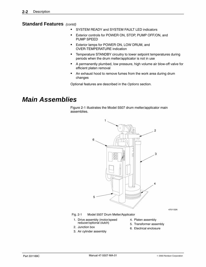
Main Assemblies Figure 2-1 illustrates the Model 5507 drum melter/applicator mainassemblies.
4701133A
1
2
3
4
5
6
Fig. 2-1 Model 5507 Drum Melter/Applicator
1. Drive assembly (motor/speedreducer/optional clutch)
2. Junction box3. Air cylinder assembly
4. Platen assembly5. Transformer assembly6. Electrical enclosure

Description 2-3
Part 331169C� 2003 Nordson Corporation Manual 47-5507-MA-01
Controls and Indicators Controls and indicators for the Model 5507 drum melter/applicator arelocated both inside and outside the electrical enclosure box.
Logic Control Unit See Figure 2-2. The solid-state Logic Control Unit (LCU) is located insidethe lockable electrical enclosure. The temperature control panel (1), LCUcircuit board (2), and �F/�C display slide switch/display board (3) arecomponents of the LCU.
4701135
4
2
1
3
Fig. 2-2 LCU Components
1. Temperature Control Panel2. LCU Circuit Board
3. �F/�C Display Slide Switch/DisplayBoard
4. Enclosure Door

Description2-4
Part 331169C � 2003 Nordson CorporationManual 47-5507-MA-01
Temperature Control PanelSee Figure 2-3. The temperature control panel consists of dialpotentiometers for setting the application temperature (setpoint) andover-temperature of each zone.
There are three zones in single-hose units which correspond to the PLATEN(1); HOSE 1 (2); and GUN 1 (3).
There are two additional zones in dual-hose units: HOSE 2 (4), and GUN 2(5).
The temperature range for each zone is 38−232�C (100−450�F). Thesetpoint and over-temperature settings will vary according to the adhesivematerial you are using.
4701136A
12
3
4 5
Fig. 2-3 Temperature Control Panel
1. PLATEN setpoint andover-temperature
2. HOSE 1 setpoint andover-temperature
3. GUN 1 setpoint andover-temperature
4. HOSE 2 setpoint andover-temperature (dual hose only)
5. GUN 2 setpoint andover-temperature (dual hose only)

Description 2-5
Part 331169C� 2003 Nordson Corporation Manual 47-5507-MA-01
LCU Circuit BoardSee Figure 2-4. The temperature SETBACK switch (1) and platen heatercontrol dip switch (2) are located on the LCU circuit board.
4701145C
SETBACKPLATEN
ALL ZONESSW2
TP
2
R4
TP
5
SW
1
OP
EN
12
2
1
Fig. 2-4 LCU Circuit Board Detail
1. Setback slide switch SW2 2. Platen dip switch SW1
The temperature SETBACK switch (or standby feature) enables a standbycondition for the platen or all zones of the drum melter in which temperatureis lowered to a predetermined level during periods of inactivity.
The platen heater control dip switch SW1 is preset at the factory formaximum efficiency in the platen heating mechanism.
�F/�C Display Slide SwitchThe �F/�C Display Switch shows the display of temperature zones in eitherdegrees Fahrenheit or Celsius. Slide the switch into the up position fordegrees Fahrenheit or into the down position for degrees Celsius.

Description2-6
Part 331169C � 2003 Nordson CorporationManual 47-5507-MA-01
Electrical Enclosure Panel The LCU display panel, power/pump control panel, and main disconnectswitch are located on the front panel of the electrical enclosure box. The aircylinder elevator control valve and platen removal selector switch arelocated on the side panel of the electrical enclosure box. The airfilter/regulator and air pressure gauge are located along the back panel ofthe electrical enclosure box.
LCU Display PanelSee Figure 2-5. The LCU display panel consists of the digital temperaturedisplay (14), zone selector switch (12), zone output (amber) LEDs (11),SYSTEM READY (green) LED (1), and SENSOR FAULT (red) LED (2).
4701137B
CH 1
CH 2CH 3
CH 4CH 5
SENSORFAULT
POWER ON
OVER−TEMP
LOW DRUM
STOP
1 GUN
WARNING
ON
OFFSTANDBY 2 GUN
SYSTEMREADY
MODEL5507
BULK MELTER
APPLICATOR
1 2 3 4 5
12
11
13
10 9
7
614
8
PLATEN
Fig. 2-5 Electrical Enclosure Front Panel (Dual-Hose Version Shown)
1. SYSTEM READY LED2. SENSOR FAULT LED3. POWER ON pushbutton4. STOP pushbutton5. PUMP OFF/ON switch
6. Main disconnect switch7. Pump speed potentiometer
(1 GUN)8. Pump speed potentiometer
(2 GUN)9. STANDBY switch
10. LOW DRUM indicator lamp
11. Zone output (amber) LEDs12. Zone selector switch13. OVER-TEMPERATURE indicator
lamp14. Digital temperature display

Description 2-7
Part 331169C� 2003 Nordson Corporation Manual 47-5507-MA-01
During startup, all amber LEDs for the platen and any connected hoses orguns will remain on and the SYSTEM READY LED will remain off. Oncethe platen is within 14 �C (25 �F) of the setpoint, the green SYSTEMREADY LED will come on. When the setpoint temperature is reached,power is cycled to the heaters and the amber LEDs will blink.
Turn the zone selector switch to a particular channel (CH1 for platen) todisplay the temperature in that zone.
If the temperature in any zone reaches the over-temperature setting, theOVER-TEMPERATURE INDICATOR LAMP will come on.
Power/Pump Control PanelThe power/pump control panel consists of the following:
� POWER ON pushbutton (3) (applies power to all heated zones and thepump motor)
� STOP pushbutton (4) (removes power from the pump control andheating zone circuitry)
� OVER-TEMPERATURE indicator lamp (13)
� PUMP OFF/ON switch (5)
� LOW DRUM (10) indicator lamp
� STANDBY (9) switch
� PUMP SPEED potentiometer(s) (7, 8) (one or two depending upon thenumber of hoses/guns)
Main Disconnect SwitchThe main disconnect switch (6) routes electrical power to the drummelter/applicator master power contactor when set to the ON position.

Description2-8
Part 331169C � 2003 Nordson CorporationManual 47-5507-MA-01
Elevator Control Valve and Platen Removal SwitchSee Figure 2-6. The three-position ELEVATOR CONTROL valve directs theair supply to above or below the pistons located inside the air cylinders.
4701138
ELEVATORCONTROL
PLATENREMOVAL
Fig. 2-6 Elevator Control Valve and Platen Removal Switch
When the ELEVATOR CONTROL valve is in the up position, air is forcedinto the air cylinders below the pistons; the piston/crossover/driveassemblies and platen are raised.
When the ELEVATOR CONTROL valve is in the down position, air is forcedinto air cylinders above the pistons; the piston/crossover/drive assembliesand platen are lowered.
When the ELEVATOR CONTROL valve is in the neutral (center) position, noair is forced into the air cylinders; the piston/crossover/drive assemblies andplaten remain stationary.
The PLATEN REMOVAL selector switch is engaged along with the elevatorcontrol valve to remove the platen from the drum of material.
When the PLATEN REMOVAL selector switch is engaged, 48 kPa (7 psi) ofair is delivered to the platen removal blow-off valve. This air supply assiststhe platen removal assemblies in raising the platen out of the drum duringthe changeout procedure.

Description 2-9
Part 331169C� 2003 Nordson Corporation Manual 47-5507-MA-01
Air Filter/Regulator and Air Pressure GaugeSee Figure 2-7. The air filter/regulator (3) and air pressure gauge (4) arelocated along the back panel of the electrical enclosure box. The 551−689kPa (80−100 psi) shop air supply, which controls air cylinder operation, isconnected to the quick disconnect fitting (1) at this location. The unitoperating air pressure is adjusted with the filter/regulator handle (2).
The air pressure gauge provides a visual means of checking the unitoperating air pressure.
4701139
4
3
1
2
Fig. 2-7 Air Filter/Regulator and Air Pressure Gauge
1. Quick disconnect fitting2. Filter/Regulator handle
3. Filter/Regulator4. Air pressure gauge

Description2-10
Part 331169C � 2003 Nordson CorporationManual 47-5507-MA-01
Functional Description When power is applied to the unit, the temperature control circuitry for theplaten, hose, and gun channels activates and continuously routes inputpower to the heating element in each component. The amber zone outputLEDs will remain on while the input power is being routed to the channels.
See Figure 2-8. The green SYSTEM READY LED lights and the pumpcontrol is enabled when the platen is within 14 �C (25 �F) of the setpointtemperature and the motor start-up time delay has elapsed (if equipped withthis option). Move the elevator control valve to the down position. Theair-driven pistons (4) lower the platen (5) into the drum (3).
4701134A
1
9
2
7
6
4
3
5
138
Fig. 2-8 Material Flow Diagram
1. Hose2. Gerotor pump3. Drum
4. Piston5. Platen6. Solid material
7. Melted material8. Gun9. Manifold

Description 2-11
Part 331169C� 2003 Nordson Corporation Manual 47-5507-MA-01
When the RTD senses that the component temperature has reachedsetpoint, power will begin cycling to the components to maintain thistemperature and the amber LEDs will blink.
When the gun is triggered, the pump (2) draws the melted material directlybelow the platen (7) through a port in the bottom of the platen to the pumpmanifold (9). At the pump manifold, the adhesive material is fed into one ortwo hydraulic hoses (1). Automatic or hand-operated heated guns (8) at theend of the hoses distribute the adhesive onto the substrate.
Material that is not in direct contact with the platen (6) remains solid until theplaten moves further down the drum.
The red OVER-TEMP indicator lights if a platen, hose, or gunover-temperature exists. The red SENSOR FAULT LED lights if the platen,hose, or gun RTDs fail. The amber LOW DRUM indicator lights if thematerial level in the drum is near empty. The LOW DRUM setting is useradjustable.
All channel temperatures or just the platen channel temperature can belowered to STANDBY condition (setback temperature) for extended periodsof inactivity.
The STANDBY feature and the drum changeout procedure are described inthe Operation Section.

Description2-12
Part 331169C � 2003 Nordson CorporationManual 47-5507-MA-01
Specifications Table 2-1 provides physical and operational specifications for theModel 5507 drum melter/applicator.
Table 2-1 Specifications
Part Description Note
Motor/Drive 1 hp, 1800 RPM DC motor, 10:1 gearreducer
Pump 3/4” gerotor, 11.6 cc/rev.
Platen Type Flat, PTFE-coated
Maximum Melt Rate 90 kg/hr (200 lb/hr) A
Maximum Pump Rate 100 kg/hr (220 lb/hr) A
Platen Surface Area 3090 cm� (479 in�)
Maximum Power Consumption (ServiceRequired)
29 kW B
Weight 590 kg (1300 lb) C
Dimensions (H x W x D) w/ elevator up 290 x 86 x 152 cm (114 x 34 x 60 in.)
Operating Voltage and Current 200 Vac, 50 Hz, 3 phase, 71A240 Vac, 60 Hz, 3 phase, 77A380 Vac, 50 Hz, 3 phase, 43A415 Vac, 50 Hz, 3 phase, 45A480 Vac, 60 Hz, 3 phase, 39A
Inside Drum Diameter 571 mm (22 1/2 in.)
Capacity 200 l (55 gal)
Supply Air Pressure 551−689 kPa (80−100 psi)
Operating Temperature 38−232 �C (100−450 �F)
Maximum Hose Capacity 2
Exhaust Hood Air Flow Requirements 142 l/sec (300 cfm)
NOTE A: Depends on adhesive material type and viscosity.
B: Depends on line voltage.
C: Depends on configuration.

SE
CT
ION
3
## TABSHEET ##

Installation 3-1
Part 331169C� 2003 Nordson Corporation Manual 47-5507-MA-01
Section 3Installation
Refer to the instructions provided in the Safety Notice (available inwww.emanuals.nordson.com under 5000 Series 55 Gallon DrumMelters).
WARNING: Allow only qualified personnel to perform the following tasks.Follow the safety instructions in this document and all other relateddocumentation.
Introduction This section describes how to install the Model 5507 drum melter/applicator,hoses, and guns. Procedures for routine operation of the drummelter/applicator are located in the Operation section.
Unpack the Drum Melter/Applicator No special instructions are necessary to unpack the drum melter/applicator.Normal care should be taken so that the equipment is not damaged duringunpacking.
Inspect the Drum Melter/Applicator After unpacking the drum melter/applicator, inspect the equipment fordamage, integrity, and completeness.
� Compare the received contents of the containers from Nordson to thebill of materials to verify that all necessary materials were received.
� Remove metal shavings, packing material, or any other foreign materialthat might be in the air or adhesive ports.
� Unlatch and open the electrical enclosure door. Make sure all electricalconnections inside the enclosure and on the inside of the door are tight.
� Inspect hoses for broken connectors, tears in the outer cover, kinks, orother damage.
� Inspect all fasteners and mechanical connections for tightness.
Report any shortages or damage to a Nordson representative.

Installation3-2
Part 331169C � 2003 Nordson CorporationManual 47-5507-MA-01
Installation See Figure 3-1 and refer to the Description section for physical dimensionsof the Model 5507 drum melter/applicator.
NOTE: Position the unit so the hose will reach from the pump to the gunwithout straining or crimping the hose.
Use the following procedure to install the drum melter/applicator.
1. Position the unit in a location that allows access to all controls and theplaten area.
4701140A
2.90 m(9 ft 6 in.)
1.52 m(5 ft)
.86 m(2 ft 10 in.)
(when platen isin its fully
raised position)
Fig. 3-1 Model 5507 Clearances

Installation 3-3
Part 331169C� 2003 Nordson Corporation Manual 47-5507-MA-01
2. Level the unit as necessary by installing shims near the four bolt holes inthe frame base. Then use 5/16 in. bolts and washers to secure the unitto the floor.
3. Check that the elevator control valve is in the neutral (center) position.
NOTE: Nordson recommends that a customer-supplied shut-off valvebe installed in the air supply line in order to isolate the unit formaintenance or other procedures.
4. Set the main filter/regulator (See Figure 3-2, (2)) to 0 kPa/psi. Securean external, unlubricated air supply of at least 551−689 kPa(80−100 psi) to the quick disconnect fitting (1).
4701139
4
3
1
2
Fig. 3-2 Air Filter/Regulator and Air Pressure Gauge
1. Quick disconnect fitting2. Filter/Regulator handle
3. Filter/Regulator4. Air pressure gauge

Installation3-4
Part 331169C � 2003 Nordson CorporationManual 47-5507-MA-01
Installation (contd)
5. Check that the �F/�C slide switch (See Figure 3-3, (3)) is set for yourapplication (UP = �F, DOWN = �C).
4701228A
4
21
3
5
Fig. 3-3 LCU Organization
1. Temperature control panel2. LCU circuit board3. �F/�C Display slide
switch/display board
4. Enclosure Door5. Location of C4 on
circuit board
6. See Figure 3-4. Set SETBACK slide switch SW2 (1), on the LCU circuitboard, to either PLATEN or ALL ZONES (the factory setting is ALLZONES). Adjustment instructions for this feature are provided in theOperation section.
4701227A
SETBACKPLATEN
ALL ZONES SW2
TP
2
R4
TP
5
SW
1
OP
EN
12
2
1
Fig. 3-4 LCU Circuit Board Detail
1. Setback slide switch SW2 2. Dip switch SW1

Installation 3-5
Part 331169C� 2003 Nordson Corporation Manual 47-5507-MA-01
7. Locate the Platen Heater Control Circuit DIP switch SW1 (2) on the LCUcircuit board and verify the proper settings. Switch 1 should be set toOPEN and switch 2 should be set to CLOSED.
8. Units equipped with the Automatic Shutdown option:
See Figure 3-5. Locate the timer module (2) inside the electricalenclosure and note its setting (the factory-setting is position3−approximately one hour). The timer is calibrated in increments of1 through 6. One is equal to approximately 10 minutes and 6 is equalto approximately 120 minutes.
4701146A
CONN2
KM
KA1
OFFOPEN COVER
ON
L1 L2 L3
F1 F2 F3
1 2 3 2
31
KT1
123 4
56
XT
1X
T2
Fig. 3-5 Electrical Enclosure Interior
1. Input power terminals2. Automatic shutdown timer module
3. Ground stud

Installation3-6
Part 331169C � 2003 Nordson CorporationManual 47-5507-MA-01
Electrical Connections
WARNING: Risk of electrical shock. Disconnect and lock out inputelectrical power before connecting the input power supply line to this unit.Failure to observe could result in personal injury or death.
NOTE: Read and follow the procedures in the Operation section beforesupplying input power to the unit.
The Model 5507 drum melter/applicator is available with the following inputvoltages:
� 200 VAC� 240 VAC� 380 VAC� 415 VAC� 480 VAC
The input voltage for the unit is stamped on the nameplate on the front ofelectrical enclosure.
Use the following procedure to make the drum melter/applicator electricalconnections.
1. Install a customer-supplied switch, with a lockout, in the input powersupply line to the unit.
2. Remove the knockout plug in the top of the electrical enclosure andinstall a customer-supplied strain relief at this access hole.
NOTE: The input power supply line may be routed into the electricalenclosure by way of another location. However, this will require acustomer-produced hole in the electrical enclosure.
3. Route a 3-phase input power supply line through the strain relief andinto the electrical enclosure.
NOTE: The power supply must be rated at least 80 amps and be within10% of the voltage rating specified on the drum melter/applicatornameplate.
4. See Figure 3-5. Unlatch and open the electrical enclosure and connectinput power to terminals L1, L2 and L3 (1) at the main disconnectswitch.
5. Connect the input power supply line ground wire to the copper terminalat the ground stud (3).
6. Connect a reliable, non-floating earth ground to the ground stud insidethe enclosure by way of the input power supply line access hole.

Installation 3-7
Part 331169C� 2003 Nordson Corporation Manual 47-5507-MA-01
Automatic Gun Installation
WARNING: Risk of electrical shock. Complete gun-to-hose connectionsbefore completing hose-to-unit electrical connections. Failure to observecould result in personal injury or death.
NOTE: Refer to the Troubleshooting section for wiring diagrams andschematics. Also, refer to the product manual for your particular extrusiongun.
NOTE: The gun mount should be protected from vibration and secured sothat the gun will not change position during operation.
Use the following procedure to install automatic gun(s) to the drummelter/applicator.
1. See Figure 3-6. Install the gun on the parent machine in properalignment with the substrate (1). For optimum control of bead position,optimum response time, and minimum heat loss, nozzles should bepositioned approximately 13 mm (0.5 in.) from the substrate.
4201071A1 2 3
Fig. 3-6 Automatic Gun Installation
1. Installing the gun on the parentmachine
2. Making the hydraulic and electricconnections
3. Tightening the hydraulicconnection

Installation3-8
Part 331169C � 2003 Nordson CorporationManual 47-5507-MA-01
Automatic Gun Installation (contd)
2. Coat the gun fitting threads with Never Seez and connect the hoseswivel connector to the gun fitting (2).
3. Insert the gun electrical plug into the socket at the end of the hose (2).
4. Use two wrenches to tighten the hose connection−one wrench to holdthe gun fitting stationary, and the other to tighten the hose swivelconnector (3).
5. Wrap the hose/gun hydraulic connection with insulation.
6. Install a filter/regulator and solenoid (both customer-supplied) onthe gun.
7. Set the gun filter/regulator to 0 kPa/psi.
NOTE: Nordson recommends that a customer-supplied 3-way lockoutvalve be installed in the air supply line in order to isolate the gun formaintenance or other procedures.
8. Connect an external, unfiltered and unlubricated air supply to thegun solenoid. The air supply pressure must not exceed689 kPa (100 psi). The recommended operating pressure is276−482 kPa (40−70 psi).
9. Connect the 120 VAC gun solenoid valve leads to the following terminalsinside the electrical enclosure.
� Single-Hose Units−XT1-13 and XT1-15
� Dual-Hose Units−XT1-11 and XT1-15 (Gun 1)/XT1-12 andXT1-15 (Gun 2)
10. Remove jumper J3 connected to C2-1 and C2-3.
11. Remove wires 21A (at C4-12), 86A (at C2-3) and 87A (at C2-2).Then connect the timer or triggering device output leads (must be drycontact, normally open) to the following terminals inside the electricalenclosure.
� Single-Hose Units−C4-12 and C2-3
� Dual-Hose Units−C4-12 and C2-3 (Gun 1)/C4-12 and C2-2 (Gun 2)
NOTE: The timer outputs should be dry contact closure or another typeof solid-state switching device capable of switching 12 VDC.

Installation 3-9
Part 331169C� 2003 Nordson Corporation Manual 47-5507-MA-01
Manual Gun Installation
WARNING: Risk of electrical shock. Complete gun-to-hose connectionsbefore completing hose-to-unit connections. Failure to observe could resultin personal injury or death.
Refer to the appropriate manual for specific handgun for installationprocedures.
Hose Connections
WARNING: Risk of electrical shock. Do not connect the hose electricallyuntil the hose hydraulic connections are completed. Failure to observecould result in personal injury or death.
Use the following procedure to connect the hose(s) to the drummelter/applicator.
1. See Figure 3-7. Route the hose from the drum melter/applicator to theproduction work station in accordance with the following guidelines:
� Route the hoses without bundling or pinch points.
� Do not allow hoses to contact sharp or abrasive surfaces.
� Do not allow a large surface area of the hose to contact a coldsurface, such as a floor, that will conduct heat away from the hose.
� Keep a minimum of 13 mm (0.50 in.) between the hoses.
� Do not place hoses inside a closed cover which insulates the hosesand prevents them from dissipating heat. This could causeoverheating and damage to the equipment.

4710131B
Installation3-10
Part 331169C � 2003 Nordson CorporationManual 47-5507-MA-01
Hose Connections (contd)
4701143
X=13 mm (0.50 in.)
R=203 mm (8.00 in.)
X
Fig. 3-7 Adhesive Hose Installation Guidelines
NOTE: Each hose is equipped with a pigtail-type cordset at one end.Install each hose with this cordset closest to the manifold.
2. See Figure 3-8. Coat the hose fitting threads on the pump manifold withNever Seez. Then thread the hose swivel connector onto the manifoldhose fitting.
NOTE: If you are using a dual-hose gear pump manifold anda second hose will not be used, install a pipe plug in theunused hose port.
3. Use two wrenches to tighten the hose connection−one wrench to holdthe hose fitting stationary, and another wrench to tighten the hose swivelconnector.
4. Repeat steps 1−3 to install a second hose, if necessary.
5. Insert the hose 1 electrical plug at the cordset end of the hose into theupper socket on the side of the electrical enclosure. On dual-hose units,insert the hose 2 electrical plug into the lower socket.
Fig. 3-8 Hose-to-ManifoldConnection

Installation 3-11
Part 331169C� 2003 Nordson Corporation Manual 47-5507-MA-01
Bulk Feed Installation Use the following procedure when installing the bulk feed hoses.
1. Complete hydraulic connections at the delivery end of the hose asrequired for your application.
2. If an external motor start trigger is not installed, then install a jumperbetween terminals C2-1 and C2-3 inside the electrical enclosure. Referto the wiring diagram for your unit in the Troubleshooting section for theexact location of terminal block C2.
NOTE: Installation of this jumper enables the PUMP OFF/ON switch toenergize the motor directly when the switch is set to the ON position.
3. Insert the hose 1 electrical plug at the cordset end of the hose into theupper socket on the side of the electrical enclosure. On dual hose units,insert the hose 2 electrical plug into the lower socket.
CAUTION: Route the exhaust duct to a safe location outside of thebuilding. Failure to observe may result in personal injury.
Exhaust Hood Setup Use the following procedure to connect the exhaust duct to the hood.
1. Attach a customer-supplied exhaust duct to the neck of the hood andsecure it in place with customer-supplied duct tape or clamps.
NOTE: A minimum air flow of 142 liters/second (300 cfm) through thehood is required for proper operation.
2. Restore input power to the unit, activate the shop exhaust system, andproceed with operation as described in the Operation section.
Miscellaneous Install any options that were shipped separate from the Model 5507 unitafter the above installations are complete. Refer to the Options section fordescriptions of available options. Contact a Nordson representative withany questions.

Installation3-12
Part 331169C � 2003 Nordson CorporationManual 47-5507-MA-01

SE
CT
ION
4
## TABSHEET ##

Operation 4-1
Part 331169C� 2003 Nordson Corporation Manual 47-5507-MA-01
Section 4Operation
Refer to the instructions provided in the Safety Notice (available inwww.emanuals.nordson.com under 5000 Series 55 Gallon DrumMelters).
WARNING: Allow only qualified personnel to perform the following tasks.Follow the safety instructions in this document and all other relateddocumentation.
Introduction Use these procedures for operation of the Model 5507 drummelter/applicator:
� Preparation for routine operation
� Routine operation
� Normal shutdown
� Short-term shutdown and startup
� Temperature setback (STANDBY) adjustment
� Drum changeout
� Adhesive material changeout
Read the Description section before proceeding to gain an understanding ofthe drum melter/applicator assemblies and the controls and indicators.
Preparation Complete the following procedures before operating the drummelter/applicator for the first time or when changing operational settings oradhesive types:
WARNING: When using polyurethane reactive materials, do not set theapplication temperatures or over-temperature limits of the platen, hose(s),and gun(s) without first consulting the adhesive manufacturer and theTechnical Data Sheet. Failure to follow the recommendations in theTechnical Data Sheet can lead to personal injury. If equipment is notoperated in compliance with Technical Data Sheet recommendations,Nordson reserves the right to refuse service for this equipment.

Operation4-2
Part 331169C � 2003 Nordson CorporationManual 47-5507-MA-01
Set Temperatures Set the application temperatures and over temperatures as follows:
1. Check that the input power to the unit is OFF and that the maindisconnect switch is in the OFF position.
2. Check that the elevator control valve is in the neutral (center) position.
3. Open the electrical enclosure door.
WARNING: The over-temperature setting must be at least 28 �C (50 �F)below the flash point of the adhesive being used. Failure to observe cancause personal injury or equipment damage.
4. Using the platen, hose, and gun setpoint potentiometers, set theapplication temperature at or below the temperature recommended inthe Technical Data Sheet.
5. Using the platen, hose, and gun over-temperature potentiometers, setthe over-temperature 28 �C (50 �F) above the application temperature.
NOTE: On dual-hose units where only one hose and gun are beingused, set the over-temperature of the unused channels at least 28 �C(50 �F) above the application temperature. Otherwise, falseover-temperature warnings may occur.
6. If installed, verify that the factory default setting for the start-up timer willsatisfy your application requirements. Refer to Start-Up Timer in theOptions section for details.
7. Close and latch the electrical enclosure door.
Set Controls Set the other drum melter/applicator controls and check the hoses asfollows:
1. If installed, check that the Temperature STANDBY switch on theelectrical enclosure front panel is set to OFF. Setting this switch to ONdisables the Automatic Shutdown feature.
2. Turn the PUMP SPEED potentiometer(s) on the electrical enclosurefront panel fully counterclockwise.
3. Set the air filter/regulator to 207 kPa (30 psi) as indicated on its gauge.
NOTE: It may be necessary to increase or decrease thepressure at the filter/regulator from this original setting whenusing high or low viscosity material.
4. Check that the adhesive hoses are not kinked or pinched.

Operation 4-3
Part 331169C� 2003 Nordson Corporation Manual 47-5507-MA-01
Load the Drum
WARNING: Hot! Risk of burns. Wear heat-protective clothing and safetygoggles, and heat-protective gloves.
CAUTION: Do not attempt this procedure unless the unit is at applicationtemperature. Failure to observe could cause damage to the platen seal.
Install the drum of material as follows:
1. Set the main disconnect switch to the ON position and press thePOWER ON button.
2. Allow the drum melter/applicator to heat to application temperature andcheck that the SYSTEM READY light is on.
3. Place the elevator control valve in the UP position, allowing the platen toreach its maximum height. Leave the elevator control valve in the UPposition.
4. If installed, open the platen guard.
WARNING: Use only drums rated to withstand 103 kPa (15 psi) of airinjection. Failure to observe and follow this warning may cause rupturing ofdrum and/or personal injury.
CAUTION: Check that the unit base is free of adhesive so that the drumsits squarely on the base. Failure to do so may result in a poor seal orincomplete emptying of the drum.
CAUTION: A dented or otherwise damaged drum may cause damage tothe platen seal, resulting in faulty equipment operation.
5. Center an open drum of material on the frame base (or in the drumhold-down assembly) directly under the platen.
6. If installed, close the platen guard.
7. Coat the platen seal with high temperature grease.
8. See Figure 4-1. Place a small tray or metal pan under the bleed port.

Operation4-4
Part 331169C � 2003 Nordson CorporationManual 47-5507-MA-01
Load the Drum (contd)
4710197A
A B C
Fig. 4-1 Bleeding the System
9. Unscrew and remove the platen T-handle from the bleed port.
10. Use the elevator control valve to slowly lower the platen into the drumuntil all trapped air is removed and there is a steady flow of materialfrom the platen bleed port.
11. Replace the platen T-handle back into the platen bleed port and tightensecurely.
The drum melter/applicator is ready for routine operation.

Operation 4-5
Part 331169C� 2003 Nordson Corporation Manual 47-5507-MA-01
Operation Use the following procedure to operate the drum melter/applicator on aroutine basis.
1. Set the main disconnect switch to the ON position and press thePOWER ON button.
2. Allow the drum melter/applicator to reach application temperature. Usethe LCU zone selector switch to verify that all heating zones are at thesetpoint temperature before proceeding.
3. If the start-up timer option is installed, wait until it times out. Refer toStart-Up Timer in the Options section for more details.
4. Turn on the input air supply to the drum melter/applicator.
5. Place the elevator control valve in the DOWN position.
6. Check to make sure material is not leaking past the platen seal.
a. If leakage is present, remove platen from drum and inspect seal fordamage. Replace if necessary. Refer to Replacing the Platen Sealin the Repair section.
b. If seal is intact, try reducing the cylinder air pressure at the mainfilter/regulator.
7. Set the PUMP OFF/ON switch to the ON position.
8. Adjust the pump speed potentiometer for the desired flow rate.
� On dual-hose units, the 1 GUN (top) pump speed potentiometer setsthe speed when one gun is triggered. The 2 GUN (bottom) pumpspeed potentiometer sets the speed when both guns are triggered atthe same time.
� On manual guns, the pump speed potentiometer should be adjustedso that material projects from the gun no more than 46 cm (18 in.).
9. Adjust the air pressure as required.
The unit is ready to apply adhesive to the substrate.

Operation4-6
Part 331169C � 2003 Nordson CorporationManual 47-5507-MA-01
Normal Shutdown Use the following procedure to shutdown the drum melter/applicator for longperiods, such as at the end of the work day.
1. Set the PUMP ON/OFF switch to the OFF position.
2. Press the STOP button on the electrical enclosure front panel.
3. Set the main disconnect switch to the OFF position.
4. Place the elevator control valve in the neutral (center) position.
5. Turn the air filter/regulator to 0 kPa/psi.
6. Trigger all guns to relieve residual hydraulic pressure.
7. On manual guns, set the trigger lock to the ON position.
Short-Term Shutdown and Startup Use the following procedure to shutdown the drum melter/applicator forshort periods, such as meal breaks and shift changes.
NOTE: If the unit is equipped with the Automatic Shutdown option, theheating channels and pump control circuitry will automatically de-energize ifno guns are triggered for at least 60 minutes. The NO GUN TRIGGERperiod is user adjustable from 10 to 100 minutes. Refer to AutomaticShutdown in the Options section.
1. Set the PUMP OFF/ON switch to the OFF position.
2. Place the elevator control valve in the neutral (center) position.
3. Turn the STANDBY switch to ON. If it becomes necessary to changethe setback temperature from the factory setting, refer to TemperatureSetback (STANDBY) Adjustment in this section.
4. To restart the unit, turn the STANDBY switch to OFF.
5. For units equipped with the Automatic Shutdown option, check that theunit is still ON. If the Auto Shutdown option has removed power,complete the Routine Operation procedure described in this section.
6. Allow the drum melter/applicator to reach application temperature. Usethe LCU zone selector switch to verify that all heating zones are at thesetpoint temperature before proceeding.
7. Place the elevator control valve in the DOWN position.
8. Set the PUMP OFF/ON switch to the ON position and resume normaloperation.

Operation 4-7
Part 331169C� 2003 Nordson Corporation Manual 47-5507-MA-01
Temperature Setback (STANDBY) Adjustment Use the following procedure to change the setback temperature of theadhesive material.
NOTE: The temperature setback feature is factory set to reducetemperatures 100 �F/56 �C below setpoint for all zones.
WARNING: Risk of electrical shock. Use extreme caution whenperforming voltage checks. Do NOT touch the meter probes whenperforming these checks. The input terminals on the fused main disconnectswitch remain electrically energized even with the main disconnect switchset to the OFF position. Only qualified personnel should service thisequipment. Failure to observe and follow this warning may result inpersonal injury or death.
1. Apply input power to the drum melter and set the main disconnectswitch to the ON position.
2. Unlatch the electrical enclosure door.
3. Use an insulated, flat blade screwdriver to turn the recessed slot headscrew below the main disconnect switch counterclockwise. At the sametime, open the electrical enclosure door.
4. See Figure 4-2. Locate the Logic Control Unit (LCU) (2) inside thelockable electrical enclosure.
4701135
4
2
1
3
Fig. 4-2 LCU Organization
1. Temperature Control Panel2. LCU Circuit Board
3. �F/�C Display Slide Switch/DisplayBoard
4. Enclosure Door

Operation4-8
Part 331169C � 2003 Nordson CorporationManual 47-5507-MA-01
Temperature Setback (STANDBY) Adjustment (contd)
5. See Figure 4-3. Locate trim potentiometer R4 and test points TP2 andTP5.
4701227A
SETBACKPLATEN
ALL ZONESSW2
TP
2
R4
TP
5
SW
1
OP
EN
12
2
1
Fig. 4-3 LCU Circuit Board Detail
1. Setback slide switch SW2 2. Dip switch SW1
6. Connect a voltmeter (DC scale) to test points TP2 and TP5.
7. Use a short, insulated, flat blade screwdriver to turn trim pot R4clockwise to increase the number of setback degrees orcounterclockwise to decrease the number of setback degrees.
NOTE: Two millivolts equals 1 �F. For example, to obtain a 28 �C(50 �F) setback differential, adjust the trim pot counterclockwise fromthe factory setting until the voltmeter displays 100mVDC (0.1 VDC).
8. See Figure 4-3. Locate switch SW2. Slide the switch to the PLATENposition if only the platen temperature should be set back. Slide theswitch to ALL ZONES to set back all heating zones.
NOTE: If only the platen heating channel is set back, all other heatingzones remain at their setpoint temperature.
9. Close and latch the electrical enclosure door and resume normaloperation.

Operation 4-9
Part 331169CE 2003 Nordson Corporation Manual 47-5507-MA-01
Drum ChangeoutWARNING: Hot! Risk of burns. Wear heat-protective clothing and safetygoggles, and heat-protective gloves.
CAUTION: Do not attempt this procedure unless the unit is at applicationtemperature. Failure to observe could cause damage to the platen seal(s).
Use the following procedure to change the drum.
1. Check that the SYSTEM READY light is on.
2. Set the PUMP OFF/ON switch to the OFF position.
3. Place the elevator control valve in the neutral (center) position.
4. Turn the PLATEN REMOVAL selector switch to the ON position andplace the elevator control valve in the up position. Air will flow from theblow-off valve and the platen will begin to rise.
5. When the platen clears the drum and reaches its maximum height,release the PLATEN REMOVAL selector switch. Leave the elevatorcontrol valve in the up position.
6. If installed, open the platen guard.
7. Remove the drum.
WARNING: Use only drums rated to withstand 103 kPa (15 psi) of airinjection. Failure to observe and follow this warning may cause personalinjury.
CAUTION: Check that the unit base is free of adhesive so that the drumsits squarely on the base. Failure to do so may result in a poor seal orincomplete emptying of the drum.
CAUTION: A dented or otherwise damaged drum may cause damage tothe platen seal, resulting in faulty equipment operation.

Operation4-10
Part 331169C � 2003 Nordson CorporationManual 47-5507-MA-01
Drum Changeout (contd)
8. Center the new drum of material on the frame base (or in the drumhold-down assembly) directly under the platen.
9. If installed, close the platen guard.
10. Coat the platen seal with high temperature grease.
11. See Figure 4-1. Place a small tray or metal pan under the bleeder port.
12. Unscrew and remove the platen T-handle from the bleed port.
13. Use the elevator control valve to slowly lower the platen into the drumuntil all trapped air is removed and there is a steady flow of materialfrom the platen bleed hole.
14. Replace the T-handle back into the bleed port and tighten securely.
15. Resume normal operation.
Adhesive Changeout When changing from one material to another, Nordson recommends thatthe system be flushed as detailed in the Maintenance section. Flushing thesystem removes traces of old material from the drum melter/applicator.

SE
CT
ION
5
## TABSHEET ##

Maintenance 5-1
Part 331169C� 2003 Nordson Corporation Manual 47-5507-MA-01
Section 5Maintenance
Refer to the instructions provided in the Safety Notice (available inwww.emanuals.nordson.com under 5000 Series 55 Gallon DrumMelters).
WARNING: Allow only qualified personnel to perform the following tasks.Follow the safety instructions in this document and all other relateddocumentation.
CAUTION: Faulty or damaged hoses are not field-repairable and must bereplaced. Contact your Nordson representative for replacement and returninformation.
Introduction This section provides preventive maintenance procedures for the Model5507 drum melter/applicator and hoses. Maintenance instructions for theguns can be found in the gun manual.
Complete the following tasks before attempting the procedures in thissection:
� Read through the entire procedure while at the unit to become familiarwith the required steps. It may be necessary to refer to the Repairsection and the illustrated parts lists in the Parts section for exactcomponent locations, sizes, etc.
� Check that the required tools, replacement parts, and service items areat hand.
� Read and follow all safety precautions in the Safety section and in thissection.

Maintenance5-2
Part 331169C � 2003 Nordson CorporationManual 47-5507-MA-01
Relieve System Pressure WARNING: Hot! Risk of burns. Do not attempt to loosen any manifold,hose, or gun connection until system hydraulic pressure has been relieved.Failure to observe could result in serious personal injury.
1. Place the elevator control valve in the neutral (center) position,
2. Manually trigger the gun(s) until no material flows.
3. See Figure 5-1. Open the gear pump manifold drain valve to relieveresidual hydraulic pressure.
4701190C
Fig. 5-1 Opening the Manifold Drain Valve
4. Disconnect the air supply from the unit.

Maintenance 5-3
Part 331169C� 2003 Nordson Corporation Manual 47-5507-MA-01
General System Maintenance Use the guidelines in Table 5-2 to maintain your drum melter/applicator.
Table 5-2 Maintenance Schedule
Frequency Procedure
Daily Inspect the hose hydraulic connections. Refer to Inspecting theHose Hydraulic Connections in this section.
Keep the adhesive material supply clean and free ofcontaminants that can lead to poor pump performance and/orclogged gun nozzles.
Clean all applicator and hose exterior surfaces. Refer toCleaning the Exterior in this section.
Weekly Clean the top of the platen, frame, air cylinders, and electricalenclosure. Remove dirt, dust, and excess material buildup onthe platen.
Inspect the platen seals for excess material leakage. Replacethe seals if necessary as described in the Repair section.
Inspect the pneumatic tubing for kinks and bends. Repair orreplace as necessary.
Monthly Check the speed reducer lubricant level as described in thissection.
Inspect the electrical connections inside the electrical enclosure.Tighten any loose connections.
Clean blow-off valve. Repair or replace as needed.
After the First 250 Hours of Serviceand Every Six Months of ServiceThereafter
Change the speed reducer lubricant as described in this section.
As Required Flush the system, especially when changing to a differentadhesive. Refer to Flushing the System in this section.

4701211C
ELEVATORCONTROL
PLATENREMOVAL
Maintenance5-4
Part 331169C � 2003 Nordson CorporationManual 47-5507-MA-01
Daily Maintenance
Inspect Hose Hydraulic Connections 1. Relieve hydraulic pressure as described earlier in this section.
2. Inspect the hose fittings for tightness or cross-threading.
3. If the hose fittings are loose, use one wrench on the hose connector andanother wrench on the hose fitting to tighten the hose connection.
4. If the hose fittings are cross-threaded, unscrew and reconnect properly.
5. Replace the hoses if damaged.
6. Close the manifold manual valve and reconnect the input air supply.
Clean the Exterior 1. Wipe off dirt, dust, and debris from the top of the platen, frame, air
cylinders, and electrical enclosure.
2. Wipe off adhesive residue from the platen and manifold.
3. Wipe off adhesive residue from the hose fittings and the hose braid.
NOTE: Keep the braid of the hose free of adhesive. Built-up materialcan cause kinking when the hose is moved from one position to another.
Monthly Maintenance
Blow-off Valve Maintenance
WARNING: Wear heat protective clothing and safety glasses. Failure to doso may result in severe burns.
Check the Blow-off Valve 1. Raise the platen out of the pail by following the Pail Changeout
instructions in the Operation section.
2. See Figure 5-2. Place the elevator control lever to the neutral position.
3. Turn the platen removal switch to OFF.
4. Place the elevator control lever in the UP position.
5. Turn the platen removal switch to ON.
6. Listen for air flow.
Fig. 5-2 Platen Elevator andRemoval Controls

Maintenance 5-5
Part 331169C� 2003 Nordson Corporation Manual 47-5507-MA-01
7. Wipe off surface of the platen with a plastic knife or spatula.
8. If possible, look to see if the needle lifts up from the surface of theplaten.
Clean the Blow-off Valve 1. Raise the platen out of the pail by following the Pail Changeout
instructions in the Operation section.
2. Place the elevator control lever in the neutral position.
3. Turn the platen removal switch to OFF.
4. Place the elevator control lever in the UP position.
5. Wipe off the surface of the platen with a plastic knife or spatula.
6. See Figure 5-3. Remove the 2 blow-off valve assembly screws (5) andremove the needle assembly (3) and tube (2).
NOTE: If the assembly cannot be removed, remove the valve assemblyscrews and thread them into the threaded holes (4). This will drive theassembly out.
4701213A
ÇÇÇÇÇÇÉÉÉÉ
ÉÉÉÉ
3
2
1 1
11
4
4 5
5
Fig. 5-3 Opening the Manifold Drain Valve
1. Bolt2. Tube3. Needle Assembly
4. Threaded Holes5. Blow-off Valve Assembly Screw

Maintenance5-6
Part 331169C � 2003 Nordson CorporationManual 47-5507-MA-01
Clean the Blow-off Valve (contd)
7. Remove the 2 bolts (1) and separate the needle assembly from thetube.
8. Clean needle assembly and tube of any adhesive.
9. Visually check to be sure no adhesive is working back into the tube orneedle areas.
10. Check for any broken or worn parts. Replace as needed. Refer toPlaten Blow-off Assembly in the Parts section.
11. Re-assemble and replace assembly.
Check the Speed Reducer Lubricant The speed reducer lubricant should be checked at least every month andmore frequently under severe conditions (moist, dirty, or corrosiveenvironments or where rapid temperature changes occur).
Use the following procedure to check the speed reducer lubricant level.Have a small tray or metal pan and a hex wrench on hand to complete thisprocedure.
1. Press the STOP pushbutton and set the main disconnect switch to OFF.
2. See Figure 5-4. Unscrew the plastic plug (1) from the filler hole.
4701153A
2
3
4
1
5
Fig. 5-4 Speed Reducer Filler Hole and Drain Opening
1. Plastic filler hole and plug2. Speed reducer3. Speed reducer driven shaft
4. Drain plug5. Oil level plug

Maintenance 5-7
Part 331169C� 2003 Nordson Corporation Manual 47-5507-MA-01
3. Place a small tray or metal pan under the oil level hole on the rear of thegear housing, then use a hex wrench to remove the socket head oil levelplug (5).
4. The oil level should be up to the bottom of this hole.
5. If the level is low, add oil through the filler hole until oil begins to flowfrom the oil level hole.
6. When the oil stops draining from the oil level hole, replace the sockethead oil level plug.
7. Reinstall the plastic filler plug.
8. Set the main disconnect switch to ON, press the POWER ON button,and resume normal operation.
Change the Speed Reducer Lubricant The speed reducer lubricant should be changed after the first 250 hours ofservice and every six months or 2,500 hours of service afterwards.
NOTE: Some oil types may be incompatible. Check the oil type receivedwith the unit (listed in Table 5-3) and continue to use this type or anequivalent. Drain and flush the speed reducer housing with a light oil beforechanging to a different oil.
NOTE: A speed reducer stored for an extended period of time as a spareshould be filled completely with oil prior to storage. Drain the oil to theproper level before placing the reducer in service.
Use the following procedure to change the speed reducer lubricant level.Have a small tray or metal pan and a hex wrench on hand to complete thisprocedure.
1. Press the STOP pushbutton and set the main disconnect switch to OFF.
2. See Figure 5-4. Place a tray or metal pan under the speed reducerdrain hole, then use a hex wrench to remove the drain plug (4).
3. Use a hex wrench to remove the oil level plug (5).
4. Unscrew the plastic plug (1) from the filler hole.
5. After the old lubricant has drained from the housing, reinstall the bottomdrain plug.
CAUTION: Do not overfill or underfill the gear housing. Failure to observemay cause excessive friction in the gear housing and premature equipmentwear and failure.

Maintenance5-8
Part 331169C � 2003 Nordson CorporationManual 47-5507-MA-01
Change the Speed Reducer Lubricant (contd)
6. Refer to Table 5-3. Pour the recommended lubricant into the filler holeuntil it begins to flow from the oil level hole.
7. When oil stops draining from the oil level hole, reinstall the socket headoil level plug.
8. Reinstall the plastic filler plug.
9. Set the main disconnect switch to ON, press the POWER ON button,and resume normal operation.
Table 5-3 Recommended Lubricants
AmbientTemperature
Range
Boston GearLubricant*
ISO Grade ViscositycSt@40°C
AGMA LubricantNo.
-9.4 ° to 15.5 °C(15 ° to 60 °F)
R&O Gear Oil-100
HD Gear Oil-100
100 90 to 110 3 or 3 EP
10 ° to 51.7 °C(50 ° to 125 °F)
R&O Gear Oil−150
HD Gear Oil−150
150 135 to 165 4 or 4 EP
* Equivalent lubricant must conform to AGMA Standard Specification #250.03 or AGMA lubricant numberindicated and pour point should be equal to or below the minimum ambient temperature encountered.
Flush the System WARNING: Hot! Risk of burns. Wear heat-protective clothing and safetygoggles. Failure to observe may result in serious personal injury.
Use the following procedure periodically to remove dirt and charred materialfrom adhesive passages and surfaces, or before changing from oneadhesive type to another when the two adhesives are not compatible.
Before changing adhesives contact the adhesive suppler to ensurecompatibility and to determine the proper flushing material to use. Have asmall tray or metal pan and a hex wrench on hand to complete thisprocedure.

Maintenance 5-9
Part 331169C� 2003 Nordson Corporation Manual 47-5507-MA-01
Add Flushing Material Add flushing material as follows:
1. If a drum of material is installed, remove it as described in the DrumChangeout procedure in the Operation section.
2. Relieve system hydraulic pressure as described in this section.
3. Remove the gun(s) from the hose(s), then secure the free hose ends toan empty drum which will be used to collect flushing material pumpedthrough the system.
4. Clean each gun in the system as needed. Refer to the gun manual forinformation on gun disassembly, cleaning, and rebuilding.
WARNING: Risk of electrical shock. Failure to disconnect and lock outinput power may result in personal injury or death.
5. Press the STOP button, set the main disconnect switch to the OFFposition, and lock out input power to the unit.
6. Refer to the appropriate wiring diagram in the Troubleshooting section.To ensure that the pump will activate and force flushing material throughthe system with the gun(s) removed, open the electrical enclosure doorand install a jumper wire between terminals C2-1 and C2-3.
WARNING: Use the flushing material at the manufacturer’s recommendedtemperature which is below the flushing material’s flash point. Failure toobserve could result in a fire hazard.
7. Adjust the platen and hose setpoints to the flushing materialmanufacturer’s recommended temperature.
8. Close and latch the enclosure door.
CAUTION: Check that the unit base is free of adhesive so that the drum offlushing material sits squarely on the frame base. Failure to do so mayresult in a poor seal or incomplete emptying of the drum.
CAUTION: A dented or otherwise damaged drum may cause damage tothe platen seal, resulting in faulty equipment operation.
9. Load a drum of flushing material on the frame base (or in the drumhold-down assembly) directly under the platen as described in theLoading the Drum procedure in the Operation section.

Maintenance5-10
Part 331169C � 2003 Nordson CorporationManual 47-5507-MA-01
Circulate the Flushing Material Throughout the System Pump the flushing material through the system as follows:
1. Pump the flushing material through the system and into the empty drumuntil the material is free of char and other contaminants.
NOTE: Placing a strainer over the collection drum allows flushingmaterial to be reused.
2. Press the STOP button, set the main disconnect switch to the OFFposition, and lock out input power to the unit.
3. Open the electrical enclosure door and remove the jumper wire fromterminals C2-1 and C2-3. Reset the platen and hose setpointtemperatures. Close the electrical enclosure door.
4. Reattach the gun(s) to the hose(s).
5. Restore input power to the unit, set the main disconnect switch to ON,and press the POWER ON pushbutton.
6. Replace the drum of flushing material with a new drum of adhesive asdescribed in the Drum Changeout procedure in the Operation section.
7. Turn the PUMP ON/OFF switch to the ON position and trigger the gun(s)until all traces of the flushing material have been removed from thesystem.
The drum melter/applicator is ready for routine operation.

SE
CT
ION
6
## TABSHEET ##

Troubleshooting 6-1
Part 331169C� 2003 Nordson Corporation Manual 47-5507-MA-01
Section 6Troubleshooting
Refer to the instructions provided in the Safety Notice (available inwww.emanuals.nordson.com under 5000 Series 55 Gallon DrumMelters).
WARNING: Allow only qualified personnel to perform the following tasks.Follow the safety instructions in this document and all other relateddocumentation.
WARNING: Risk of electrical shock. Lock out input power as directed. Theinput terminal block remains charged even when the main disconnect switchis set to OFF. Failure to observe could result in personal injury or death.
General troubleshooting procedures for the hose and gun are included.Refer to the hose or gun manual for specific troubleshooting information.
The procedures are presented in tables that list the problems, possiblecauses, and corrective actions. Note that a problem may have more thanone possible cause. Therefore, refer to all tables before beginning tocorrect a problem. Also, check that the required tools, replacement parts,and service items for the corrective action procedure are at hand.
During the daily visual inspection, correct obvious causes of malfunctionsuch as broken or missing electrical pins or wires or damaged hose plugs.

Troubleshooting6-2
Part 331169C � 2003 Nordson CorporationManual 47-5507-MA-01
Problem Page
Adhesive Application TroubleshootingProcedures
1. Adhesive spitting on extrusion 6-4
2. Waviness in bead deposit 6-4
3. Excessive adhesive at beginning of bead 6-4
4. Excessive adhesive at end of bead 6-5
5. Adhesive stringing at cut-off 6-5
6. Adhesive drooling from gun 6-5
7. Unequal deposits between nozzles inmulti-module installations
6-6
8. Adhesive bouncing or splashing from substrate 6-6
9. Adhesive not penetrating substrate 6-7
10. Adhesive gelling 6-7
11. Adhesive charring in system 6-7
12. Adhesive fuming or smoking 6-7
Hydraulic Troubleshooting Procedures
1. No or little adhesive output 6-8
2. Adhesive leaking at hose connection 6-9
Pneumatic Troubleshooting Procedures
1. Platen elevator not working 6-10
2. Platen removal mechanism not working 6-13
Electrical Troubleshooting Procedures
1. System ready LED not illuminated 6-17
2. No or little adhesive output 6-17
3. Drive shaft rotating counterclockwise 6-18
4. Drive shaft not rotating 6-18
5. Drive motor not rotating 6-21
6. Platen not heating 6-24
7. Hose or gun not heating 6-29
8. Red OVER-TEMP indicator lamp comes on 6-30
9. Red OVER-TEMP indicator lamp not working(unit shuts down)
6-32
10. Red SENSOR FAULT indicator lamp comes on 6-34
11. POWER ON indicator lamp stays off 6-35
12. Amber LOW DRUM indicator lamp not working 6-39
13. LCU not controlling channels 6-40
14. Channels overheating 6-41

Troubleshooting 6-3
Part 331169C� 2003 Nordson Corporation Manual 47-5507-MA-01
Opening the Electrical Enclosure with Power On WARNING: Risk of electrical shock. This procedure is used whenmeasuring voltages across wiring connections. Exercise extreme cautionwhen performing voltage checks. Failure to observe could result inpersonal injury or death.
See Figure 6-1. Some of the following troubleshooting procedures willrequire an open electrical enclosure door with the power to the unit on:
1. Unlatch the enclosure door (2).
2. Loosen the slot head screw (1) directly below the main disconnectswitch.
3. Open the door.
4701156A
1
2
Fig. 6-1 Opening the Electrical Enclosure Door with Power On
1. Slot head screw 2. Latch

Troubleshooting6-4
Part 331169C � 2003 Nordson CorporationManual 47-5507-MA-01
Adhesive Application Troubleshooting The following table provides procedures for troubleshooting adhesiveapplication problems.
Problem Possible Cause Corrective Action
1. Adhesivespitting onextrusion
Adhesive output exceeds maximumcontinuous delivery rate of system
Lower the pump speed until a constantstream of adhesive is produced.
Air trapped under platen Stop the system and open the bleedvalve to remove trapped air.
Adhesive level in drum is low If the LOW DRUM indicator is on,complete the drum changeout procedureas described in the Operation section.
2. Waviness inbead deposit
Temperature setpoints lower thanrecommended applicationtemperature
Increase the temperature setpoints torecommended application temperature.
Low ambient temperature inapplication area
Increase the ambient temperature inthe application area (minimumrecommended temperature is0�C (32�F )).
Guns and nozzles subject to draft orbreeze
Prevent draft or breeze at the nozzles.
Nozzle too far from substrate Reposition the nozzle closer to thesubstrate (recommended distance is13 mm/0.50 in. from the substrate).
3. Excessiveadhesive atbeginning ofbead
Nozzle too large, resulting inexcessive instantaneous delivery rate
Use the proper size nozzle.
Nozzle too far from substrate Reposition the nozzle closer to thesubstrate (recommended distance is13 mm/0.50 in. from the substrate).
Partially plugged nozzle Clean or replace the nozzle.
Insufficient air pressure to gun Increase the air pressure to the gun asrequired.

Troubleshooting 6-5
Part 331169C� 2003 Nordson Corporation Manual 47-5507-MA-01
Problem Possible Cause Corrective Action
4. Excessiveadhesive at endof bead
Adhesive too cold Increase the channel setpoints asrequired.
Insufficient air pressure to gun Increase the air pressure to the gun asrequired.
5. Adhesivestringing atcut-off
Nozzle positioned too far fromsubstrate
Reposition the nozzle closer to thesubstrate (recommended distance is13 mm/0.50 in. from the substrate).
Adhesive too viscous Increase the channel setpoints slightlyor change to an adhesive with a lowerviscosity.
Cold adhesive Increase the gun channel setpoint(s) asrequired.
Gun speed too slow Use a faster-acting gun, use anair-piloted relay valve between thesolenoid and the gun, or reduce thedistance between the solenoid and thegun.
Gun temperature too low Increase the gun temperature asrequired.
6. Adhesivedrooling fromgun
Spring tension of gun too low Re-adjust the gun spring tension asrequired. Refer to the gun manual.
Ball or needle and/or seat of gunmodule worn or partially clogged bychar
Clean or replace the gun module.

Troubleshooting6-6
Part 331169C � 2003 Nordson CorporationManual 47-5507-MA-01
Adhesive Application Troubleshooting (contd)
Problem Possible Cause Corrective Action
7. Unequaldepositsbetween nozzlesin multi-moduleinstallations
Different size nozzles are being used Use the same size nozzles.
Unequal spring tension or improperneedle lift adjustment in zero-cavityguns
Adjust the gun modules as instructed inthe gun manual.
Nozzle clogged or damaged Clean or replace the nozzle asinstructed in the gun manual.
Foreign adhesive in gun module Rebuild or replace the gun module.
Insufficient and/or unequal airpressure to guns
Adjust the air pressure as required.
Hydraulic pressure not equal at guns Compensate for the difference by usingdifferent nozzle sizes or adjusting thegun travel as described in the gunmanual.
Debris or slight imperfections innozzles
Clean or replace the nozzles.
Adhesive in air motor section of gunmodule
Rebuild or replace the gun module.
8. Adhesivebouncing orsplashing fromsubstrate
Adhesive too hot Decrease the channel setpoints asrequired.
Adhesive viscosity too low Decrease the channel setpoints slightlyor change to an adhesive with a lowerviscosity.
Nozzle diameter too small Change to a larger diameter nozzle.
Too much adhesive Lower the pump speed.
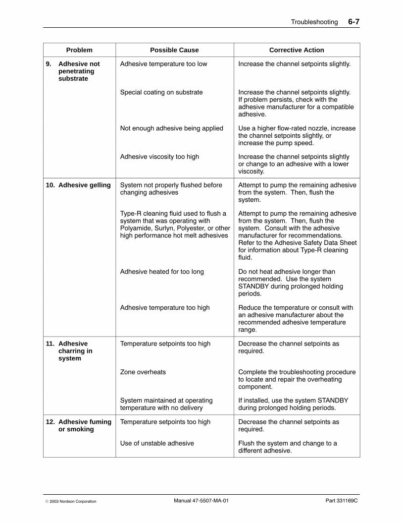
Troubleshooting 6-7
Part 331169C� 2003 Nordson Corporation Manual 47-5507-MA-01
Problem Possible Cause Corrective Action
9. Adhesive notpenetratingsubstrate
Adhesive temperature too low Increase the channel setpoints slightly.
Special coating on substrate Increase the channel setpoints slightly.If problem persists, check with theadhesive manufacturer for a compatibleadhesive.
Not enough adhesive being applied Use a higher flow-rated nozzle, increasethe channel setpoints slightly, orincrease the pump speed.
Adhesive viscosity too high Increase the channel setpoints slightlyor change to an adhesive with a lowerviscosity.
10. Adhesive gelling System not properly flushed beforechanging adhesives
Attempt to pump the remaining adhesivefrom the system. Then, flush thesystem.
Type-R cleaning fluid used to flush asystem that was operating withPolyamide, Surlyn, Polyester, or otherhigh performance hot melt adhesives
Attempt to pump the remaining adhesivefrom the system. Then, flush thesystem. Consult with the adhesivemanufacturer for recommendations.Refer to the Adhesive Safety Data Sheetfor information about Type-R cleaningfluid.
Adhesive heated for too long Do not heat adhesive longer thanrecommended. Use the systemSTANDBY during prolonged holdingperiods.
Adhesive temperature too high Reduce the temperature or consult withan adhesive manufacturer about therecommended adhesive temperaturerange.
11. Adhesivecharring insystem
Temperature setpoints too high Decrease the channel setpoints asrequired.
Zone overheats Complete the troubleshooting procedureto locate and repair the overheatingcomponent.
System maintained at operatingtemperature with no delivery
If installed, use the system STANDBYduring prolonged holding periods.
12. Adhesive fumingor smoking
Temperature setpoints too high Decrease the channel setpoints asrequired.
Use of unstable adhesive Flush the system and change to adifferent adhesive.

Troubleshooting6-8
Part 331169C � 2003 Nordson CorporationManual 47-5507-MA-01
Hydraulic Troubleshooting Procedures The following table provides troubleshooting procedures for the drummelter/applicator’s hydraulic system.
NOTE: Some materials may require 1−2 hours to reach applicationtemperature.
Problem Possible Cause Corrective Action
1. No or littleadhesive output(Refer to electricaltroubleshootingalso)
Lack of hydraulic flow due tomalfunctioning hose, gun or nozzle
Verify that all zones are up totemperature. If yes:
a. Place the elevator control valve in theneutral (center) position.
b. Check that the T-handle bleed rod isin the bleed port.
c. Place a small tray or pan under thepump manifold drain valve.
d. Open the pump manifold drain valveand place the elevator control valvein the down position.
e. Turn the pump on at low speed.
f. If the adhesive output is normal at themanifold, turn off the pump, close themanifold drain valve, and remove thenozzle.
g. Turn the pump on and open the gun.If the output is normal without thenozzle, clean and replace the nozzle.
h. If there is no or little output with thenozzle removed, turn off pump.Bleed off hydraulic pressure atmanifold drain valve, then re-closevalve. Remove gun from hose.
i. Turn pump on. If material does notflow freely through hose with gunremoved, replace the hose.
j. If hose is operating properly, rebuildor replace the gun (refer to specificgun manual).
Continued...

Troubleshooting 6-9
Part 331169C� 2003 Nordson Corporation Manual 47-5507-MA-01
Problem Possible Cause Corrective Action
1. No or littleadhesive output(contd.)
Air trapped in pump/platen Check for trapped air:
a. Turn the PUMP selector switch to offand place the elevator control valvein the neutral (center) position.
b. Unscrew and remove the T-handlebleed rod from the platen.
c. Place a small tray or metal pan underthe platen bleed port.
d. Use the elevator control valve tolower the platen into the drum. If airis discharged from the bleed port,purge the trapped air from the systembefore resuming operation.
Gear pump malfunctioning Check that the drive shaft is rotatingproperly and in a clockwise direction asdescribed in the Drive shaft rotatingcounterclockwise and Drive shaft notrotating problems in this section.
Replace or rebuild the gear pumpassembly as described in the Repairsection.
Cured PUR in pump cavity Disassemble the pump as described inthe Repair section and clean the pumpas recommended by the adhesivesupplier.
Sheared coupling key or gerotor key Disassemble the pump as described inthe Repair section and replace the key ifworn.
Pressure relief valve open Disassemble the pump as described inthe Repair section and replace thepressure relief valve if open.
2. Adhesive leakingat hoseconnection
Loose or cross-threaded connection Check the hose to manifold connection.
Faulty hose connector O-ring at thehose to gun connection
Replace the O-ring as described in theRepair section.

Troubleshooting6-10
Part 331169C � 2003 Nordson CorporationManual 47-5507-MA-01
Pneumatic Troubleshooting Procedures Refer to the following tables for troubleshooting procedures for the drummelter/applicator’s pneumatic system. See Figure 6-2 for the pneumaticwiring diagram.
Problem Possible Cause Corrective Action
1. Platen elevatornot working
Air filter/regulator malfunctioning Check the air filter/regulator:
a. Set the air filter/regulator pressure to0 kPa/psi (never disconnect the inputair line without first turning off theinput (shop) air). Then disconnectthe input air supply from the quickdisconnect fitting.
b. Disconnect the air line from theoutput side of the filter/regulator andreconnect the input air supply to theunit at the quick disconnect fitting
c. Turn the filter/regulator handleclockwise to increase the air pressureand listen for air exhaust. Also, turnthe handle counterclockwise andlisten for exhaust.
d. If there is no air exhaust from theoutput side of the filter/regulator whenthe handle is turned clockwise, or ifthere is air exhaust when the handleis turned counterclockwise, set thefilter/regulator pressure to 0 kPa/psiand disconnect the input air supplyfrom the quick disconnect fitting.
e. Replace the filter/regulator.
Continued...

Troubleshooting 6-11
Part 331169C� 2003 Nordson Corporation Manual 47-5507-MA-01
Problem Possible Cause Corrective Action
1. Platen elevatornot working(contd.)
Elevator control valve malfunctioning Check the elevator control valve:
a. Set the air filter/regulator pressure to0 kPa/psi, then disconnect both airlines from the output side of theelevator control valve. Tag each airline.
b. Set the filter/regulator pressure to138 kPa (20 psi).
c. Place the elevator control valve in theup position to listen for air flow at thelower elbow fitting, in the downposition to listen for air flow from theupper elbow fitting, and in the neutral(center) position to verify no air flow.
d. If air does not flow from the lower orupper elbow fitting, or flows when theelevator control valve is in the neutralposition, set the filter/regulatorpressure back to 0 kPa/psi, andreplace the elevator control valve.
Piston assemblies malfunctioning Check the piston assemblies:
a. Set the filter/regulator pressure to0 kPa/psi and place the elevatorcontrol valve in the neutral (center)position.
b. Disconnect the air line from the upperelbow fitting on the output side of theelevator control valve.
c. Set the filter/regulator pressure to138 kPa (20 psi) and place theelevator control valve in the upposition.
d. If the crossover assembly risesand/or air continues to flow from theopen air line, replace or rebuild thepiston assemblies as described in theRepair section.
Continued...

Troubleshooting6-12
Part 331169C � 2003 Nordson CorporationManual 47-5507-MA-01
Pneumatic Troubleshooting Procedures (contd)
Problem Possible Cause Corrective Action
1. Platen elevatornot working(contd.)
Piston assemblies malfunctioning(contd.)
e. If the crossover assembly does notrise and there is no air flow from theopen air line then check the platenremoval valve:
f. Disconnect the air line elbow to thebottom air cylinder from the platenremoval valve, place the elevator inthe up position and note whether ornot there is air flow.
g. Place the elevator control valve in theneutral position, turn the platenremoval valve on, return the elevatorcontrol valve to the up position, andnote whether or not there is air flow.
h. Refer to Table 6-4 for appropriatecorrective action.
Table 6-4 Air Line Check for Platen Removal Valve
Problem Possible Cause Corrective Action
No air flow present No air flow present Replace platen removal valve.
No air flow present Air flow present Replace 30 psi regulator.
Air flow present No air flow present Replace 10 psi regulator.
Air flow present Air flow present Platen removal valve is okay. No actionneeded.

Troubleshooting 6-13
Part 331169C� 2003 Nordson Corporation Manual 47-5507-MA-01
Problem Possible Cause Corrective Action
2. Platen removalmechanism notworking
Air cylinder head leaking Check for air leakage:
a. Use leak detector fluid around theshaft at the cylinder heads to checkfor excessive air leakage with theelevator control valve in the DOWNposition.
b. If the air is leaking from the cylinderhead, set the filter/regulator pressureto 0 kPa/psi and disconnect the inputair supply from the quick disconnectfitting.
c. Replace or rebuild the cylinder headassemblies as described in theRepair section.
Platen removal switch malfunctioning Check the removal switch:
a. Set the air filter/regulator pressure to0 kPa/psi.
b. Disconnect the air line from the90� elbow fitting at the platenblow-off valve.
c. Set the filter/regulator to 138 kPa(20 psi).
d. Place the elevator control valve in theup position, then engage the PLATENREMOVAL selector switch.
- If air flows from the air line:normal indication. Reconnectthe air line, return the elevatorcontrol to neutral, and go toPlaten blow-off valvemalfunctioning.
- No air flows from the air line:possible blockage at thePLATEN REMOVAL switch orbad air line connection. Clearthe blockage at the PLATENREMOVAL switch or correct thebad air line connection.
Continued...

Troubleshooting6-14
Part 331169C � 2003 Nordson CorporationManual 47-5507-MA-01
Pneumatic Troubleshooting Procedures (contd)
2. Platen removalmechanism notworking (contd.)
Preset regulator malfunctioning Check the regulator:
a. Set the air filter/regulator pressure to0 kPa/psi.
b. Disconnect the large, flexible air linefrom the fitting at the platen blow-offvalve.
c. Set the filter/regulator to 138 kPa(20 psi).
d. Place the elevator control valve in theup position, then engage the PLATENREMOVAL selector switch.
- Air flows from the hose:reconnect hose and go to Platenblow-off valve malfunctioning.
- No air flows from hose:defective preset regulator or badair line connection. Repair orreplace the preset regulator orcorrect the bad air lineconnection.
Continued...

Troubleshooting 6-15
Part 331169C� 2003 Nordson Corporation Manual 47-5507-MA-01
2. Platen removalmechanism notworking (contd.)
Platen blow-off valve malfunctioning Check the blow-off valve:
a. Visually inspect the bottom of theplaten for adhesive that may beblocking the blow-off valve air outlet.Remove any adhesive blocking theair outlet.
b. Set the filter/regulator to 138 kPa(20 psi).
c. Place the elevator control valve in theup position, then engage the PLATENREMOVAL selector switch.
d. If the platen blow-off valve does nottrigger (needle retracts) or air doesnot flow out, set the filter/regulatorpressure back to 0 kPa/psi andrebuild or replace the platenblow-off valve. Refer to PlatenBlow-off Assembly in the Partssection.
e. Reassemble the valve and connectthe air lines to the valve assembly.Check that the air lines areconnected correctly. (See PneumaticAssembly Platen Removal in theParts section.)

Troubleshooting6-16
Part 331169C � 2003 Nordson CorporationManual 47-5507-MA-01
Pneumatic Troubleshooting Procedures (contd)
4701191A
5 PORT ROTARYVALVE (PLATENREMOVAL)
FILTER/REGULATOR
SHOP AIRSUPPLY
FACTORYPRESET
7 PSI
7 PSI
TO PLATEN
CHECK VALVEREGULATOR
PRESET10 PSI
(NON−RELIEVING)
IN OUT
REGULATORPRESET30 PSI
RIGHTLEFTCYLINDER
QUICKEXHAUST
MUFFLER
CYLINDER
IN OUT
GEROTOR PUMP PNEUMAIC DIAGRAM REMOTE BLOW−OFF.MANUAL ELEVATOR CONTROL.
4 WAY HAND VALVE(ELEVATOR CONTROLS)
IN/P
EXH
OUT/A
OUT2/B
EA P EB
A B
Fig. 6-2 Pneumatic Schematic Diagram

Troubleshooting 6-17
Part 331169C� 2003 Nordson Corporation Manual 47-5507-MA-01
Electrical Troubleshooting Procedures The following table provides troubleshooting procedures for the drummelter/applicator’s electrical system.
Problem Possible Cause Corrective Action
1. System readyLED notilluminated
Empty drum Replace drum.
Platen temperature is not within 14�C(25� F) of setpoint
Refer to Platen not heating problem inthis section.
Start delay timer has not timed out Verify the amount of time set on thetimer. Timer starts when system isturned on.
Heaters not turned on Press the POWER ON button.
2. No or littleadhesive output(Refer to hydraulictroubleshootingalso)
No input power to the applicator Check that input power is connected tothe drum melter/applicator.
Main disconnect switch not on Set the main disconnect switch to theON position.
Unit not switched on Press the POWER ON button; the whitelamp should come on. If the white lampdoes not come on or goes off, refer tothe POWER ON lamp stays off problemin this section.
Pump not on Turn the PUMP selector switch to ON.
Green SYSTEM READY light is off Wait until the platen channel hasreached setpoint temperature and theSYSTEM READY green light goes on.
One or more zones are not heating Use the zone selector switch and thedigital display to check the platen, hose,and gun channel temperatures. If anyzone fails to reach setpoint temperature,refer to the Platen not heating or theHose or gun not heating problem in thissection.
Red SENSOR FAULT indicator is on Refer to the Red SENSOR FAULTindicator lamp comes on problem in thissection.
Temperature settings of one or morechannels are too low for the adhesive
Increase the channel setpoints asrequired.
Continued...

Troubleshooting6-18
Part 331169C � 2003 Nordson CorporationManual 47-5507-MA-01
Electrical Troubleshooting Procedures (contd)
Problem Possible Cause Corrective Action
No motor start trigger Check to make sure one of the followingis connected:
- Manual gun trigger (connectedthrough hose to unit cordset)
- External level control trigger(must be dry contact closure,N.O., rated to switch 12 VDCconnected across C4-12 andC2-3).
- Jumper (18 AWG wire), J3,connected across C2-1 andC2-3. (Connect jumper forcontinuous motor operation).
3. Drive shaftrotatingcounterclockwise (when viewedfrom above theunit)
Wire connections reversed Press the STOP button, disconnect andlock out input power.
Remove the motor end cap and reversethe 44B and 45B wire connections at themotor.
4. Drive shaft notrotating
Drum empty Replace drum.
Wires loose or damaged Press the STOP button, disconnect andlock out input power.
Open the electrical enclosure door andreposition or replace any loose ordamaged wires.
Gun trigger switch malfunctioning Press the STOP button, disconnect andlock out input power.
Open the electrical enclosure door andcheck for continuity between terminalsC2-1 and C2-3 with the gun triggerswitch activated. If continuity does notexist, replace the gun trigger switch.
Pump selector switch malfunctioning Press the STOP button, disconnect andlock out input power.
Open the electrical enclosure door andcheck the PUMP selector switch forcontinuity with the switch set to on. Ifcontinuity does not exist, replace thePUMP switch.
Continued...

Troubleshooting 6-19
Part 331169C� 2003 Nordson Corporation Manual 47-5507-MA-01
Problem Possible Cause Corrective Action
4. Drive shaft notrotating (contd.)
LCU is defective Check the LCU:
a. Press the STOP button, disconnectand lock out input power.
b. Open the electrical enclosure doorand install a jumper wire betweenterminals C2-1 and C2-3.
c. Close and latch the enclosure door,apply input power, and move themain disconnect switch to the ONposition.
d. Press the POWER ON button andwait for the SYSTEM READYindicator light to turn on. Turn thePUMP selector switch to ON.
e. Check to make sure one of thefollowing is connected:
- Manual gun trigger (connectedthrough hose to unit cordset)
- External level control trigger(must be dry contact closure,N.O., rated to switch 12 VDCconnected across C4-12 andC2-3).
- Jumper (18 AWG wire), J3,connected across C2-1 andC2-3. (Connect jumper forcontinuous motor operation).
f. Verify drum is not empty.
g. Open the enclosure door with thepower on as described in Openingthe Enclosure Door with Power On inthis section. Measure the voltageacross the C3-10 and XT1-16 wireconnections.
h. If the voltage is not within the rangeof 103−127 VAC, replace the LCU.
Continued...

Troubleshooting6-20
Part 331169C � 2003 Nordson CorporationManual 47-5507-MA-01
Electrical Troubleshooting Procedures (contd)
Problem Possible Cause Corrective Action
4. Drive shaft notrotating (contd.)
LCU parts are defective(dual-hose units)
Check the LCU:
a. Press the STOP button, disconnectand lock out input power.
b. Open the electrical enclosure doorand install a jumper wire betweenterminals C2-1 and C2-3.
c. Close and latch the enclosure door,apply input power, and move themain disconnect switch to the ONposition.
d. Press the POWER ON button andturn the PUMP selector switch to ON.
e. Open the enclosure door with thepower on as described in Openingthe Enclosure Door with Power On inthis section. Measure the voltageacross the XT1-16 and XT-10 wireconnections.
f. If the voltage is not within the rangeof 103−127 VAC, replace the relayKS3 or the 2-gun speed controllercard on the LCU.
Continued...

Troubleshooting 6-21
Part 331169C� 2003 Nordson Corporation Manual 47-5507-MA-01
Problem Possible Cause Corrective Action
4. Drive shaft notrotating (contd.)
Clutch not engaging when gun istriggered (units w/ optional clutch)
Check the clutch:
a. Press the STOP button, disconnectand lock out input power.
b. Open the electrical enclosure doorand install a jumper wire betweenterminals C2-1 and C2-3.
c. Close and latch the enclosure door,apply input power, and move themain disconnect switch to the ONposition.
d. Press the POWER ON button andturn the PUMP selector switch to ON.
e. Open the enclosure door with thepower on as described in Openingthe Enclosure Door with Power On inthis section. Remove the junctionbox cover and measure the voltageacross terminals 6 and 3, wires 78and 79 at the clutch power supply.
f. Remove the jumper wire.
g. If the voltage is within the range of89−99 VDC, push the STOP button,disconnect and lock out input power,and replace the clutch as describedin the Repair section.
5. Drive motor notrotating
System not ready Refer to System ready LED notilluminated problem in this section.
Over-temperature condition exists If the OVER-TEMP indicator is on, referto the Red OVER-TEMP indicator lampcomes on problem in this section.
Continued...

Troubleshooting6-22
Part 331169C � 2003 Nordson CorporationManual 47-5507-MA-01
Electrical Troubleshooting Procedures (contd)
Problem Possible Cause Corrective Action
5. Drive motor notrotating (contd.)
Wires loose or damaged Press the STOP button, disconnect andlock out input power.
If the OVER-TEMP indicator is on, referto the Red OVER-TEMP indicator lampcomes on problem in this section.
Open the enclosure door and check forloose or broken wire connectionsthroughout the circuit path. Repair orreplace wires as necessary.
Motor controller fuse is open Press the STOP button, disconnect andlock out input power.
Remove fuse F7 and test for continuity.Replace if necessary.
Pump speed potentiometermalfunctioning
Press the STOP button, disconnect andlock out input power.
Open the enclosure door and check theresistance at the pump speedpotentiometer (1 GUN). A normalreading is 5000 ohms across wires 6and 8 at terminals 3 and 5 of the motorcontroller. Replace the potentiometer ifnecessary.
PUMP SPEED potentiometer turnedfully counter clockwise
Rotate PUMP SPEED potentiometerclockwise until the desired pump speedis obtained.
Continued...

Troubleshooting 6-23
Part 331169C� 2003 Nordson Corporation Manual 47-5507-MA-01
Problem Corrective ActionPossible Cause
5. Drive motor notrotating (contd.)
PUMP OFF/ON switch malfunctioning Press the STOP button, disconnect andlock out input power.
Open the enclosure door and test forcontinuity between wires 16 and 17 atthe PUMP OFF/ON switch. Replace ifopen.
Drive motor malfunctioning Check the drive motor:
a. Press the STOP button, disconnectand lock out input power.
b. Open the enclosure door and removeone wire at the motor controller andcheck the resistance between wires44 and 45 at terminals A1 and A2 ofthe motor controller. A normalreading is 1.5−1.7 ohms.
c. If the resistance is not normal, checkfor loose or damaged wires andreplace as necessary.
d. If no loose or damaged wires arefound, replace the drive motor asdescribed in the Repair section.
Continued...

Troubleshooting6-24
Part 331169C � 2003 Nordson CorporationManual 47-5507-MA-01
Electrical Troubleshooting Procedures (contd)
5. Drive motor notrotating (contd.)
Motor controller malfunctioning Check the motor controller:
a. Set the PUMP OFF/ON switch toOFF.
b. Close and latch the enclosure doorand apply input power. Set the maindisconnect switch to ON and pressthe POWER ON button.
c. Open the electrical enclosure door asdescribed in Opening the ElectricalEnclosure Door with Power On in thissection. Measure the voltage acrosswires 11 and 62 at the motor controlterminals L1 and L2.
d. If the voltage is within the range of216−264 VAC, remove input power,remove the jumper wire, and replacethe motor controller.
e. If the voltage is not within range,remove input power and repair theconnection between fuse F7 andterminal L1, or terminal XT1-5 andterminal L2.
Speed reducer malfunctioning Replace the speed reducer as describedin the Repair section of this manual.
6. Platen notheating
Over-temperature condition exists If the OVER-TEMP indicator lamp is on,refer to the Red OVER-TEMP indicatorlamp goes on problem in this section.
Sensor fault condition exists If the SENSOR FAULT indicator is on,refer to the Red SENSOR FAULTindicator lamp comes on problem in thissection.
Continued...

Troubleshooting 6-25
Part 331169C� 2003 Nordson Corporation Manual 47-5507-MA-01
Problem Possible Cause Corrective Action
6. Platen notheating (contd.)
Fuse is open Press the STOP button, disconnect andlock out input power.
Open the electrical enclosure door andremove and check fuses F1, F2, and F3for continuity. Replace as necessary.
Wires loose or damaged Press the STOP button, disconnect andlock out input power.
Open the enclosure door and check forloose or damaged wires at terminals L1,L2, and L3 on the main fused disconnectswitch QS and throughout the circuitpath to the platen heaters. Repositionor replace as necessary.
Platen LED not functioning Refer to LCU not controlling channelsproblem in this section.
LCU malfunctioning Check the LCU:
a. Open the enclosure door asdescribed in Opening the ElectricalEnclosure Door with Power On in thissection.
b. Measure the voltage acrossterminals XT2-14 and XT1-15(wires 43 and 38).
c. If the voltage is not within the rangeof 103−127 VAC, measure thevoltage across terminals C4-1 andC4-2 (wires 52 and 43).
d. If the voltage across terminals C4-1and C4-2 is within the range of103−127 VAC, press the STOPbutton, disconnect and lock out inputpower, and replace the LCU.
Continued...

Troubleshooting6-26
Part 331169C � 2003 Nordson CorporationManual 47-5507-MA-01
Electrical Troubleshooting Procedures (contd)
Problem Possible Cause Corrective Action
6. Platen notheating (contd.)
Solid-state relays have failed Check the relays:
a. Open the enclosure door asdescribed in Opening the ElectricalEnclosure Door with Power On in thissection.
b. Measure the voltage across the inputto the solid state relay at terminals3 and 4.
c. If the input voltage is 103−127 VAC,measure the voltage across theoutput terminals 1 and 2 (wires 1 and140) at the solid-state platen heaterrelays KA1, KA3, and KA4.
d. If the input voltage to the solid staterelay across terminals 3 and 4 is not103−127 VAC, refer to LCUMalfunctioning.
e. If the solid state relay output voltageacross terminals 1 and 2 is within�10% of incoming line voltage foreither relay, the relay is faulty. Pressthe STOP button, disconnect andlockout input power, and replacerelay KA1, KA3, or KA4 asnecessary.
Master contactor (KM2) has failed Check the contactor:
a. With the main switch set to ON, pressthe POWER ON switch.
b. Open the enclosure door asdescribed in Opening the ElectricalEnclosure Door with Power On in thissection.
c. Measure the voltage across thefollowing wire pairs at contactor KM2:
- 140 and 141
- 141 and 142
- 140 and 142
Continued...

Troubleshooting 6-27
Part 331169C� 2003 Nordson Corporation Manual 47-5507-MA-01
Problem Possible Cause Corrective Action
6. Platen notheating (contd.)
Master contactor (KM2) has failed(contd.)
d. If the voltage is within �10% of linevoltage, go to step f.
e. If the voltage is not within �10% ofline voltage, refer to Solid state relayshave failed, Motor controller fuse isopen or LCU malfunctioning in thissection.
f. Measure the voltage between lineand load side of contactor KM2 at thefollowing wires:
- 142 and 32
- 141 and 31
- 140 and 30
g. If voltage is within �10% of the linevoltage, then go to step i to check coilvoltage of contactor.
h. If voltage is not within �10% of theline voltage, the contactor is okay.Refer to Platen heaters have failed inthis section.
i. Measure contactor KM2 coil voltageat wires 38X and 42F.
j. If the KM2 input coil voltage is withinthe range of 103−127 VAC, thenpress the STOP button, disconnectand lockout power, and replace theCM2 contactor.
k. If the KM2 input coil voltage is notwithin the range of 103−127 VAC,then refer to LCU malfunctioning inthis section.

Troubleshooting6-28
Part 331169C � 2003 Nordson CorporationManual 47-5507-MA-01
Electrical Troubleshooting Procedures (contd)
Problem Possible Cause Corrective Action
6. Platen notheating (contd.)
Platen thermostats have failed Check the thermostats:
NOTE: Platen overtemperaturethermostats (2) are normally closed,open on rise.
a. Press the STOP button, disconnectand lock out power.
b. Remove the platen covers asdescribed in the Repair section anddisconnect the platen thermostatleads from the porcelain wireconnectors and check for continuity.
c. Replace the faulty thermostat asdescribed in the Repair section ifnecessary.
Platen heaters have failed Check the heaters:
a. Press the STOP button, disconnectand lock out power.
b. Remove the junction box cover.
c. Measure the resistance across thefollowing wire pairs with the wiresremoved from terminal block XT4:
- 30B and 31B
- 30B and 32B
- 31B and 32B
d. Compare the resistances withTable 6-5.
e. Call your Nordson representative ifany heater is not withinspecifications.
Table 6-5 Platen Heater Cold Resistance Values in Ohms
Unit Input Voltage (VAC) Cast-In Heater (Ohms) Platen Heater Connections Wire Pairs 30/31,30/32, 31/32
200/240 13−15 Delta 4.3 −5.0
380/415 13−15 Wye 13.0 −15.0
480 13−15 Delta 17.3 −20.0

Troubleshooting 6-29
Part 331169C� 2003 Nordson Corporation Manual 47-5507-MA-01
Problem Possible Cause Corrective Action
7. Hose or gun notheating
Sensor fault condition exists If the SENSOR FAULT indicator is onand the gun is not heating, replace thegun RTD as described in the gunmanual.
If SENSOR FAULT indicator is on andthe hose is not heating, replace the hoseas described in the Installation section.
Amber channel indicator lightmalfunctioning
If all amber channel indicator LEDs areon, refer to the LCU not controllingchannels problem in this section.
Fuse is open Press the STOP button, disconnect andlock out input power.
Open the enclosure door. Removefuses F10, F11, F13, and F14 and checkfor continuity. Replace any open fuses.
Wires loose or damaged Press the STOP button, disconnect andlock out input power.
Open the enclosure door and check forloose or damaged wires throughout thecircuit path. Reposition or replace wiresas necessary.
Triac has failed Check the triacs:
a. Press the STOP button, disconnectand lock out input power.
b. Unplug the hose electricalconnections from the unit.
c. At the hose connector on the unitend, measure the resistance betweenC4 and A4 for a malfunctioning hoseand between C3 and B4 for amalfunctioning gun.
d. If the resistance is within the range of30−1100 ohms, replace the triac asfollows:
- Triac V1 for a malfunctioninghose (single-hose units)
- Triac V2 for a malfunctioning gun(single-hose units)
- Triac V3 for malfunctioninghose 2
- Triac V4 for malfunctioning gun 2
Continued...
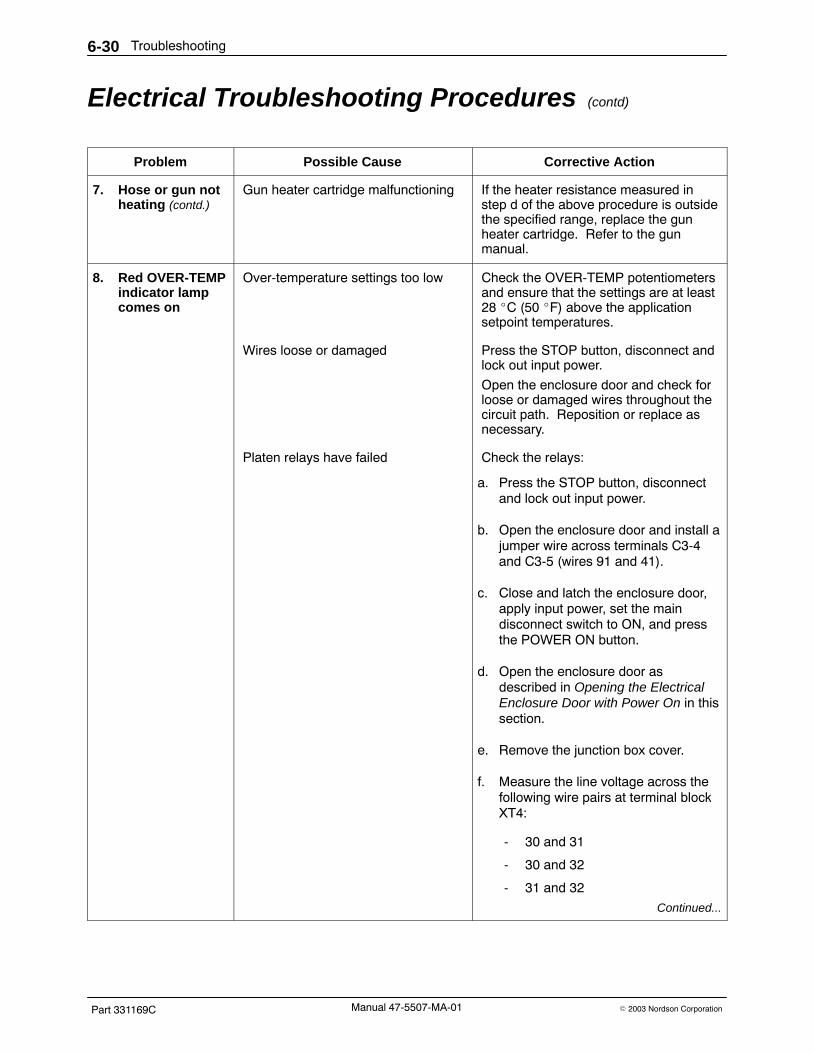
Troubleshooting6-30
Part 331169C � 2003 Nordson CorporationManual 47-5507-MA-01
Electrical Troubleshooting Procedures (contd)
Problem Possible Cause Corrective Action
7. Hose or gun notheating (contd.)
Gun heater cartridge malfunctioning If the heater resistance measured instep d of the above procedure is outsidethe specified range, replace the gunheater cartridge. Refer to the gunmanual.
8. Red OVER-TEMPindicator lampcomes on
Over-temperature settings too low Check the OVER-TEMP potentiometersand ensure that the settings are at least28 �C (50 �F) above the applicationsetpoint temperatures.
Wires loose or damaged Press the STOP button, disconnect andlock out input power.
Open the enclosure door and check forloose or damaged wires throughout thecircuit path. Reposition or replace asnecessary.
Platen relays have failed Check the relays:
a. Press the STOP button, disconnectand lock out input power.
b. Open the enclosure door and install ajumper wire across terminals C3-4and C3-5 (wires 91 and 41).
c. Close and latch the enclosure door,apply input power, set the maindisconnect switch to ON, and pressthe POWER ON button.
d. Open the enclosure door asdescribed in Opening the ElectricalEnclosure Door with Power On in thissection.
e. Remove the junction box cover.
f. Measure the line voltage across thefollowing wire pairs at terminal blockXT4:
- 30 and 31
- 30 and 32
- 31 and 32
Continued...

Troubleshooting 6-31
Part 331169C� 2003 Nordson Corporation Manual 47-5507-MA-01
Problem Possible Cause Corrective Action
8. Red OVER-TEMPindicator lampcomes on (contd.)
Platen relays have failed (contd.) g. If line voltage exists between anywire pair, press the STOP button,disconnect and lock out input power,and remove the jumper wire.Replace the platen heater relays asfollows:
- Line voltage between 30 and 31,replace KA1 and KA3
- Line voltage between 30 and 32,replace KA1 and KA4
- Line voltage between 31 and 32,replace KA3 and KA4
Platen is overheating Refer to the Channels overheatingproblem in this section.
Hose or gun triac has failed Check the triacs:
a. Press the STOP button anddisconnect and lockout input power.
b. Measure the voltage across mainterminals of the suspect triac (using300 VAC scale) indicated by thefollowing wire pairs:
- Hose 1: 19 and 63
- Gun 1: 19 and 67
- Hose 2: 22 and 82
- Gun 2: 22 and 83
c. Adjust the temperature control knobfor that channel so that the heater isfully OFF (channel LED is OFF).Triac voltage should measure210−250 VAC.
Continued...

Troubleshooting6-32
Part 331169C � 2003 Nordson CorporationManual 47-5507-MA-01
Electrical Troubleshooting Procedures (contd)
8. Red OVER-TEMPindicator lampcomes on (contd.)
Hose or gun triac has failed (contd.) d. Adjust the temperature control knobfor that channel so that the heater isfully ON (channel LED is ON). Triacvoltage should measure 0−5 VAC.
e. If any voltage reading is outside thenormal range, replace the triac.
Hose or gun is overheating Refer to the Channels overheatingproblems in this section.
9. Red OVER-TEMPindicator lampnot working (unitshuts down)
Over-temperature limit is too close tothe normal operating temperature
Check the settings:
a. Open the electrical enclosure door asdescribed in Opening the ElectricalEnclosure Door with Power On in thissection.
b. Turn the temperature controlpotentiometer for the channel inquestion fully counterclockwise.
c. Close the electrical enclosure doorand observe the OVER-TEMPindicator lamp.
d. If the OVER-TEMP lamp goes on, theover-temperature limit is set too closeto the normal operating setpoint.
e. Raise the over-temperature setting.
Continued...

Troubleshooting 6-33
Part 331169C� 2003 Nordson Corporation Manual 47-5507-MA-01
Problem Possible Cause Corrective Action
9. Red OVER-TEMPindicator lampnot working (unitshuts down)(contd.)
OVER-TEMP indicator lamp notaccurate
Check the settings:
a. Open the electrical enclosure door asdescribed in Opening the ElectricalEnclosure with Power On in thissection.
b. Compare the over-temperaturesetpoints with the LCU digitaltemperature displays for the platen,hose, and gun channels.
c. If the displayed temperatures are nothigher than the over-temperaturesettings, then an over-temperaturecondition does not exist. Refer to theLCU not controlling channels problemin this section.
Wires loose or damaged Press the STOP button, disconnect andlock out input power.
Open the enclosure door and check forloose or damaged wires throughout thecircuit path. Reposition or replace asnecessary.
Continued...

Troubleshooting6-34
Part 331169C � 2003 Nordson CorporationManual 47-5507-MA-01
Electrical Troubleshooting Procedures (contd)
Problem Possible Cause Corrective Action
10. Red SENSORFAULT indicatorlamp comes on
Wires loose or damaged Press the STOP button, disconnect andlock out input power.
Open the enclosure door and check forloose or damaged wires throughout thecircuit path. Reposition or replace asnecessary.
Faulty ribbon cable Check the ribbon cable:
a. Use the zone selector switch to checkfor a high temperature (greater thanor equal to 370�C (700 �F)) display.
b. If an extremely high temperaturereading is shown for any zone, pressthe STOP button, disconnect andlock out input power.
c. Disconnect one RTD lead in thefaulty channel and check theresistance between it and the otherRTD lead. For hoses, check thereading between pins XS1-A2 andXS1-C1.
d. If the reading is within the range of100−500 ohms, replace the ribboncable that connects the faulty channelRTD to the LCU.
Platen, gun, or hose RTD has failed If the reading in step d of the aboveprocedure is not within the range of100−500 ohms and the hightemperature zone is the platen or gun,replace the RTD of that component orrepair the RTD circuitry for that channel.
If the reading is not within range and thehigh temperature zone is the hose,replace the hose.
Continued...

Troubleshooting 6-35
Part 331169C� 2003 Nordson Corporation Manual 47-5507-MA-01
Problem Possible Cause Corrective Action
10. Red SENSORFAULT indicatorlamp comes on(contd.)
Platen RTD has failed Press the STOP button, unplug the hoseelectrical connections from the unit, andobserve the SENSOR FAULT LED.
If the SENSOR FAULT LED remains on,replace the platen RTD as described inthe Repair section.
Hose RTD has failed If the SENSOR FAULT LED goes off inthe above procedure, reconnect thehose and press the POWER ON button.
If the hose channel continues to heat upafter the setpoint temperature isreached, press the STOP button,disconnect and lock out input power,and replace the hose.
Gun RTD has failed If the SENSOR FAULT LED goes off inthe above procedure, reconnect thehose and press the POWER ON button.
If the gun channel continues to heat upafter the setpoint temperature isreached, press the STOP button,disconnect and lock out input power andreplace the gun RTD or repair the shortin the gun sensor circuit.
11. POWER ONindicator lampstays off
Lamp is blown Press the STOP button, disconnect andlock out input power.
Open the enclosure door and check thePOWER ON lamp for continuity.Replace the lamp if necessary.
Wires loose or damaged Press the STOP button, disconnect andlock out input power.
Open the enclosure door and check forloose or damaged wires throughout thecircuit path. Reposition or replace asnecessary.
Continued...

Troubleshooting6-36
Part 331169C � 2003 Nordson CorporationManual 47-5507-MA-01
Electrical Troubleshooting Procedures (contd)
Problem Possible Cause Corrective Action
11. POWER ONindicator lampstays off (contd.)
Platen thermostat has opened Check the thermostat:
a. Press the STOP button, disconnectand lock out input power, and removethe junction box cover.
b. Check for continuity betweenterminals XT3-3 and XT3-4(wires 40 and 47).
c. If continuity does not exist and theplaten is hot, refer to the ChannelsOverheating problem in this section.
d. If the platen is not hot, the platenthermostat has failed open. Replacethe thermostat as described in theRepair section.
Continued...

Troubleshooting 6-37
Part 331169C� 2003 Nordson Corporation Manual 47-5507-MA-01
Problem Corrective ActionPossible Cause
Over-temperature/sensor faultcontact on the LCU has failed openbetween C3-4 and C3-5
Check the over temperature sensor faultcontact:
a. Check to make sure there are noovertemperature or sensor faults.
b. Press the STOP button, disconnectand lock out input power.
c. Open the electrical enclosure doorand temporarily remove wire 91 fromLCU C3-4 and wire 41 from LCUC3-5. Cap both wires off withinsulators to prevent contact withother components in the cabinet.
d. Close and latch the enclosure doorand apply input power. Set maindisconnect switch to ON.
e. Open the electrical door as describedin Opening the Electrical Enclosurewith Power On in this section.
f. Check for continuity between LCUC3-4 and C3-5.
- If continuity exists, the LCUovertemperature/sensor faultcontact is okay. Press STOPbutton, disconnect and lockoutinput power. Reconnect wire 91to C3-4 and wire 41 to C3-5.
- If no continuity exists, replaceLCU.
Continued...

Troubleshooting6-38
Part 331169C � 2003 Nordson CorporationManual 47-5507-MA-01
Electrical Troubleshooting Procedures (contd)
Problem Possible Cause Corrective Action
11. POWER ONindicator lampstays off (contd.)
Fuse is open Check the main power fuses:
a. Press the STOP button, disconnectand lock out input power.
b. Check fuses F1, F2, and F3 forcontinuity.
c. If fuses F1, F2, and F3 are not open,check fuse F5 for continuity andreplace if open.
POWER ON or STOP button hasfailed
Press the STOP button, disconnect andlock out input power.
Open the enclosure door and check thePOWER ON and STOP buttons forcontinuity (the POWER ON button isN.O. and the STOP button is N.C.).Replace the button if necessary.
Main disconnect switch has failed Check the switch:
a. Remove and lockout input power tothe unit.
b. Set the main disconnect switch toON.
c. Check all three legs of the maindisconnect switch for continuity.
d. If any leg of the main disconnectswitch is open, replace the maindisconnect switch.
Continued...

Troubleshooting 6-39
Part 331169C� 2003 Nordson Corporation Manual 47-5507-MA-01
Problem Possible Cause Corrective Action
Transformer or main contactor hasfailed
Check the transformer and maincontactor:
a. Open the electrical enclosure door asdescribed in Opening the ElectricalEnclosure with Power On in thissection.
b. Measure the voltage betweenterminals XT2-4 and XT1-16(wires 50 and 38).
c. If the reading is not within the rangeof 103−127 VAC and fuses F1 and F2are okay, replace the transformer.
d. If the reading is within range, replacethe main power contactor.
12. Amber LOWDRUM indicatorlamp notworking
Lamp is blown Press the STOP button, disconnect andlock out input power.
Remove and check the bulb forcontinuity. Replace if necessary.
Limit switch arm out of position Press the STOP button, disconnect andlock out input power.
Check the limit switch arm for properalignment so that contact is made whenthe drum gets low.
Wires loose or damaged Press the STOP button, disconnect andlock out input power.
Open the enclosure door and check forloose or damaged wires throughout thecircuit path. Reposition or replace asnecessary.
Continued...

Troubleshooting6-40
Part 331169C � 2003 Nordson CorporationManual 47-5507-MA-01
Electrical Troubleshooting Procedures (contd)
Problem Possible Cause Corrective Action
12. Amber LOWDRUM indicatorlamp notworking (contd.)
Limit switch has failed Check the switch:
a. Press the STOP button, disconnectand lock out input power.
b. Disconnect wire 50E from terminalXT2-4.
c. Deflect the limit switch arm until itreaches the low drum position. Holdthe arm in that position.
d. Check for continuity between the endof wire 50E removed from XT2-4 andwire 51 at the LOW DRUM lamp.Replace the limit switch if open.
13. LCU notcontrollingchannels
Wires loose or damaged Press the STOP button, disconnect andlock out input power.
Open the enclosure door and check forloose or damaged wires throughout thecircuit path. Reposition or replace asnecessary.
Jumpers/Shorting bars not installed Press the STOP button, disconnect andlock out input power. Check thefollowing connections:
� J1 at F4 and F5 (unless transformercontrol module on 380/415 VACunits is used)
� Shorting bar at XT2-9 and 10(unless auto shutdown option isused)
Install jumpers as needed.
Loose connectors or ribbon cable Press the STOP button, disconnect andlock out input power.
Check that connectors C2 and C3 arecorrectly oriented and plugged insecurely (NOTE: Terminal #1 is atextreme left of PCB header).
Check that the ribbon cable is pluggedin properly and securely.
LCU malfunctioning Press the STOP button, disconnect andlock out input power.
Replace the LCU.Continued...

Troubleshooting 6-41
Part 331169C� 2003 Nordson Corporation Manual 47-5507-MA-01
Problem Possible Cause Corrective Action
14. Channelsoverheating
Non-standard equipment or wiringmodification being used
Press the STOP button, disconnect andlock out input power.
Check the following RTD inputs forcorrect voltage (less than 12 VDC):
� Platen: C2-19 and 20
� Channel 1: C2-16 and 17
� Channel 2: C2-13 and 14
� Channel 3: C2-10 and 11
� Channel 4: C2-7 and 8
If the reading is higher than 12 VDC,remove any non-standard equipment orwiring modification causing the RTD toreceive more than 12 VDC.
Resistor not connected (Platenoverheating)
Press the STOP button, disconnect andlock out input power.
Check that the 1,750-ohm, 11-wattresistor is connected across terminals3 and 4 of either KA1, KA3, or KA4.Install if necessary.
Platen solid-state relays have failedclosed
Check the relays:
a. With main disconnect switch set toON, press the POWER ON button.
b. Check the solid-state relays KA1,KA2, and KA3 by turning the PLATENSETPOINT potentiometer to low, butnot off.
c. Verify that amber LED on LCUtemperature controller for platen doesnot come on. When the actualtemperature is much higher thansetpoint temperature, the controllerwill not turn on the platen solid staterelays.
d. Check for line voltage between wirepairs 140/141, 141/142, and 142/143.
e. If there is line voltage for any pair,replace the faulty relay(s).
Continued...

Troubleshooting6-42
Part 331169C � 2003 Nordson CorporationManual 47-5507-MA-01
Electrical Troubleshooting Procedures (contd)
Problem Possible Cause Corrective Action
14. Channelsoverheating(contd.)
Triacs have failed (hose or gun) Check the triacs:
a. With main disconnect switch set toON, press POWER ON button.
b. Measure the voltage across mainterminals of the suspect triac (using300 VAC scale) indicated by thefollowing wire pairs:
- Hose 1: 19 and 63
- Gun 1: 19 and 67
- Hose 2: 22 and 82
- Gun 2: 22 and 83
c. Adjust the temperature control knobfor that channel so that the heater isfully OFF (channel LED is OFF).Triac voltage should measure210−250 VAC.
d. Adjust the temperature control knobfor that channel so that the heater isfully ON (channel LED is ON). Triacvoltage should measure 0−5 VAC.
e. If any voltage reading is outside thenormal range, replace the triac.
LCU malfunctioning Press the STOP button, disconnect andlock out input power.
Replace the LCU.

Troubleshooting 6-43
Part 331169C� 2003 Nordson Corporation Manual 47-5507-MA-01
Electrical Schematics and Wiring Diagrams See Figure 6-3 for the hose and gun wiring diagram.
See electrical schematic and wiring diagams for the Model 5507 drummelter/applicator included at the end of this section.
4701157
ÎÎ
ÎÎÎÎÎÎ
ÎÎÎ
C1A1A2
C4
A4
GND
C3B4B3A3B1
HOSE RTDLEADS
HOSE HEATERLEADS
HOSE-TO-UNIT CONNECTOR
WIRES FROM HOSE GUN-TO-HOSE CONNECTOR
GUN RTD
GUN
WIRE NUTGND
HOSE-TO−GUN CONNECTOR
AUTOGUN
JLIHB
HEATER
GND12356
GND12356
HOSE RTDLEADS
HOSE HEATERLEADS
HOSE-TO-UNIT CONNECTOR
JLIHB
C1A1A2
C4
A4
C3B4B3A3B1
B2C2
GND
HOSE-TO−GUNCONNECTOR
GUN-TO-HOSECONNECTOR
GUNHEATER
GUN RTD
GND
3-STATIONTERMINAL BLOCKS
GUNMANUAL
NORMALLY-OPEN LIMIT SWITCHACTIVATED BY TRIGGER
ABC
ABC
GND
WIRES FROM HOSE
C1A1A2
C4
A4
GND
HOSE-TO-UNIT CONNECTOR
HOSE HEATERLEADS
HOSE RTDLEADS
1
2
3
Fig. 6-3 Hose and Gun Wiring Diagram
1. Automatic gun and hose wiringdiagram
2. Manual gun and hose wiringdiagram
3. Transfer hose wiring diagram

Troubleshooting6-44
Part 331169C � 2003 Nordson CorporationManual 47-5507-MA-01

SE
CT
ION
7
## TABSHEET ##

Repair 7-1
Part 331169C� 2003 Nordson Corporation Manual 47-5507-MA-01
Section 7Repair
Refer to the instructions provided in the Safety Notice (available inwww.emanuals.nordson.com under 5000 Series 55 Gallon DrumMelters).
WARNING: Allow only qualified personnel to perform the following tasks.Follow the safety instructions in this document and all other relateddocumentation.
WARNING: Risk of electrical shock. Remove input power as directed. Theinput terminal block remains charged even when the main disconnect switchis set to OFF. Failure to observe could result in personal injury or death.
CAUTION: Faulty or damaged hoses are not field-repairable and must bereplaced. Contact your Nordson representative for replacement and returninformation.
Introduction This section describes repair and replacement procedures for the Model5507 drum melter/applicator. Repair and/or replacement of parts may benecessary as routine maintenance or if a component has failed and beendetected through the procedures in the Troubleshooting section.
Gun disassembly and repair information is included in the gun manual.
Do the following before attempting any of the procedures in this section:
� Verify the procedure before repairing the unit. If a fault condition hasoccurred, refer to the Troubleshooting section to determine theappropriate procedure before attempting to repair or replace a part. Ifthe fault condition is not covered in the Troubleshooting section, or ifthere is question about the proper course of action, contact a Nordsonrepresentative.
� Read the entire procedure while at the unit and become familiar with therequired steps. It may be necessary to refer to the illustrated parts listsin the Parts section for exact component locations and sizes.

Repair7-2
Part 331169C � 2003 Nordson CorporationManual 47-5507-MA-01
Introduction (contd)
� Check that the required tools, replacement parts, and service items areat hand.
� Read and follow all safety precautions in the Safety section and in thissection.
� Review Figure 7-1 shown below. Although detailed parts illustrationsaccompany each repair procedure, Figure 7-1 provides exact locationsof those parts on the drum melter/applicator unit.
4701151A
ÉÉÉÉÉÉÇÇÇ
ÇÇÇ
8
9
10
2
12
4
11
13
15
1
14
7
3
5
6
Fig. 7-1 Model 5507 Assemblies and Parts
1. Motor/Speed reducer screws andwashers
2. Speed reducer3. Speed reducer/Crossover screws
and washers4. Air cylinder shaft screws and
washers
5. Upper yoke assembly6. Driveshaft7. Air cylinder head assembly8. Air cylinder shaft9. Air cylinder
10. Column collar
11. Air piston12. Platen assembly13. Lower yoke assembly14. Crossover15. Junction box

Repair 7-3
Part 331169C� 2003 Nordson Corporation Manual 47-5507-MA-01
Hydraulic System WARNING: Do not attempt to loosen any manifold, hose, or gunconnection until system hydraulic pressure has been relieved. Refer to theMaintenance section for this procedure.
WARNING: Hot! Risk of burns. Wear heat-protective clothing and safetygoggles. Failure to observe may result in serious personal injury.
WARNING: Never use a torch or other open flame device to heat acomponent. Use only a flameless electric heat gun or electric oven withforced air circulation. Failure to observe may result in personal injury and/ordamage to the unit and nearby property.
Use the following procedures to repair components of the drummelter/applicator’s hydraulic system.
Prepare for Hydraulic System Repairs If the pump is operable, the entire system should be flushed as described inthe Maintenance section before disassembly.
If the pump is not operable, but the heating system is functioning, bring theunit to application temperature before beginning disassembly. This willsoften material throughout the system and make it easier to performdisassembly procedures.
If neither the pump nor heating system are functional, use only a flamelesselectric heat gun or similar device to melt solidified material duringdisassembly.

Repair7-4
Part 331169C � 2003 Nordson CorporationManual 47-5507-MA-01
Replace the O-Rings Use the following procedure to replace the O-ring at the gun-to-hoseconnection if there is leakage or the connection is broken. ReplacementO-rings and O-ring lubricant are required to complete this procedure.
1. Relieve system pressure as described in the Maintenance section.
2. Unscrew the hose connector from the gun fitting and remove the hose.
3. Remove the existing O-ring from the gun fitting.
4. Clean the O-ring groove in the gun fitting. Lubricate with O-ringlubricant.
5. Stretch the new O-ring enough to roll it over the hose connector or pipeplug threads and into its groove. Do not stretch the new O-ring anymore than necessary.
6. Coat the fitting and O-ring with additional O-ring lubricant.
7. Install the fitting back into the gun. Apply torque of 9.5−13.6 N�M (7−10ft-lb).
8. Connect the hose to the gun fitting and tighten with two wrenches–oneto hold the gun fitting stationary and the other to turn the hose swivelconnector.
Replace the Platen Seal Use the following procedure to replace the platen seal.
Have a piece of plywood or similar heat-resistant material on hand that isslightly larger than the platen, a blade, and high temperature grease tocomplete this procedure.
1. Bring the unit to application temperature.
2. If a drum is installed on the unit, remove the platen from the drum asdescribed in the Drum Changeout procedure in the Operation section.Position the platen so there is workspace between the platen and thetop of the drum.

4701200A
Repair 7-5
Part 331169C� 2003 Nordson Corporation Manual 47-5507-MA-01
3. Place the plywood on top of the drum.
4. Place the seal on the plywood. Use the elevator control valve to lowerthe platen until it touches the seal. Heat the seal with the platen for30−45 minutes while performing steps 5 and 6.
5. See Figure 7-2. Carefully cut the old platen seal from the platen sealgroove.
Fig. 7-2 Cutting the Seal from thePlaten Groove
6. Clean the platen lower seal groove. Then lubricate the groove with hightemperature grease.
7. Use the elevator control valve to raise the platen off of the seal.
8. See Figure 7-3. Use tire irons or similar tools to aid in stretching theseal over the platen and into the lower seal groove. Use an electric heatgun and tools as required until the seal seats in its groove. Be carefulnot to damage the PTFE covering around the seal.
NOTE: This may require the assistance of another person.
4701199A
Fig. 7-3 Replacing the Platen Seal
9. Apply a coating of high temperature grease to the platen seal.
10. Remove the plywood and resume normal operation.

Repair7-6
Part 331169C � 2003 Nordson CorporationManual 47-5507-MA-01
Replace a Platen RTD Use the following procedure to replace a platen RTD.
Have a piece of plywood or similar heat-resistant material on hand that isslightly larger than the platen diameter, heat conductive paste, Never Seez,and a replacement RTD (refer to the Parts section for the part number) tocomplete this procedure.
Remove the RTD1. If a drum of material is installed on the unit, remove it as described in
the Drum Changeout procedure in the Operation section.
2. Place the piece of plywood on the frame (or across the drum hold-downassembly).
3. Use the elevator control valve to lower the platen onto the plywood.
WARNING: Risk of electrical shock. Failure to disconnect and lock outpower may result in death or personal injury.
4. Press the STOP button, set the main disconnect switch to the OFFposition, and lock out input power to the unit.
5. See Figure 7-4. Remove the hex head screws and washers that securethe front and rear cover plates to the platen. Remove the plates.
4710077A
Fig. 7-4 Removing the Cover Plates

Repair 7-7
Part 331169C� 2003 Nordson Corporation Manual 47-5507-MA-01
6. Remove the RTD from the platen by unscrewing the connector nut.
7. See Figure 7-5. Cut the RTD leads at the platen. Remove theconnector nut and attached RTD.
4710084B
2
1
Fig. 7-5 Removing the RTD
1. RTD 2. Connector nut
8. Discard the RTD and connector nut.

Repair7-8
Part 331169C � 2003 Nordson CorporationManual 47-5507-MA-01
Install the New RTD1. Coat the replacement RTD with heat-conductive paste.
2. See Figure 7-6. Place the new connector nut from the RTD service kitonto the new RTD. Tie or tape the replacement RTD wires to the oldRTD wires, which will be used to pull the new RTD wires throughconduit.
4710085B
Fig. 7-6 Preparing to Route the Replacement RTD Wires
3. Remove the junction box cover.
4. See Figure 7-7. Disconnect platen RTD wires 58B and 59B frompositions 1 and 2 at terminal block XT3.
4701161
1 2 3 4 5 6 7 8 9 10 11 12
TO PLATEN
XT3
Fig. 7-7 Platen RTD Wire Connections
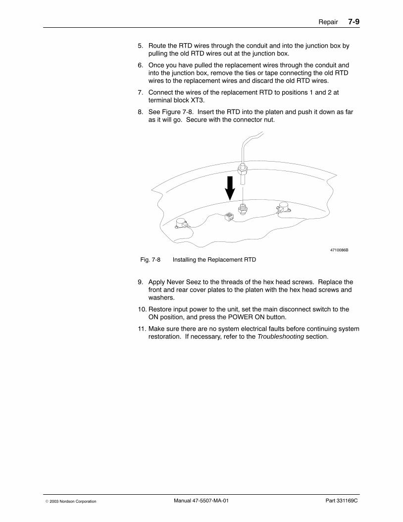
Repair 7-9
Part 331169C� 2003 Nordson Corporation Manual 47-5507-MA-01
5. Route the RTD wires through the conduit and into the junction box bypulling the old RTD wires out at the junction box.
6. Once you have pulled the replacement wires through the conduit andinto the junction box, remove the ties or tape connecting the old RTDwires to the replacement wires and discard the old RTD wires.
7. Connect the wires of the replacement RTD to positions 1 and 2 atterminal block XT3.
8. See Figure 7-8. Insert the RTD into the platen and push it down as faras it will go. Secure with the connector nut.
4710086B
Fig. 7-8 Installing the Replacement RTD
9. Apply Never Seez to the threads of the hex head screws. Replace thefront and rear cover plates to the platen with the hex head screws andwashers.
10. Restore input power to the unit, set the main disconnect switch to theON position, and press the POWER ON button.
11. Make sure there are no system electrical faults before continuing systemrestoration. If necessary, refer to the Troubleshooting section.

Repair7-10
Part 331169C � 2003 Nordson CorporationManual 47-5507-MA-01
Replace a Platen Thermostat Use the following procedure to replace a platen thermostat.
Have a piece of plywood or similar heat-resistant material on hand that isslightly larger than the platen diameter, heat conductive paste, Never Seez,and a replacement thermostat (refer to the Parts section for the partnumber) to complete this procedure.
Remove the Thermostat1. If a drum of material is installed on the unit, remove it as described in
the Drum Changeout procedure in the Operation section.
2. Place the piece of plywood on the frame (or across the drum hold-downassembly).
3. Use the elevator control valve to lower the platen onto the plywood.
WARNING: Risk of electrical shock. Failure to disconnect and lock outpower may result in death or personal injury.
4. Press the STOP button, set the main disconnect switch to OFF, and lockout input power to the unit.
5. See Figure 7-4. Remove the hex head screws and washers that securethe front and rear cover plates to the platen. Remove the plates.
6. Disconnect the thermostat to be replaced from the platen terminal block.
7. See Figure 7-9. Remove the two screws that secure the thermostat tothe platen. Remove and discard the thermostat.
4710110
Fig. 7-9 Removing the Thermostat

Repair 7-11
Part 331169C� 2003 Nordson Corporation Manual 47-5507-MA-01
Install the New Thermostat1. Coat the mating surface of the replacement thermostat with heat
conductive paste.
2. Secure the thermostat to the platen with the screws.
3. Make the thermostat terminal block connections.
4. Apply Never Seez to the threads of the hex head screws. Replace thefront and rear cover plates to the platen with the hex head screws andwashers.
5. Restore input power to the unit, set the main disconnect switch to theON position, and press the POWER ON button.
6. Make sure there are no system electrical faults before continuing systemrestoration. If necessary, refer to the Troubleshooting section.
Replace the Blow-off Valve Follow this procedure to replace the blow-off valve.
1. If there is a drum in the unit, remove it by following Drum Changeoutinstructions in the Operation section.
2. With the elevator still in the up position, wipe off the surface of the platenwith a plastic knife or spatula.
3. Place a heat-resistant support on the frame base below the platen.
4. Use the elevator control to lower the platen onto the support.
WARNING: Risk of electrical shock. Disconnect equipment from linevoltage before servicing.
5. Turn power off, place the main disconnect switch in the OFF position,and lock out power.
WARNING: System or material pressurized. Relieve pressure. Failure toobserve may result in serious burns.
6. Set the air pressure regulator to 0 kPa/psi (fully counterclockwise); thendisconnect the air supply from the unit.
7. Move the elevator control lever to the UP position to bleed all pneumaticpressure from the system.

Repair7-12
Part 331169C � 2003 Nordson CorporationManual 47-5507-MA-01
To Remove the Blow Off Valve1. Remove the 2 blow-off valve assembly screws (5) and remove the
needle assembly (3) and tube (2).
NOTE: If you cannot remove the assembly, remove valve assemblyscrews and thread them into the threaded holes (4). This will drive theassembly out.
4701213A
ÇÇÇÇÇÇÉÉÉÉ
VIEW A
VIEW A
ÉÉÉÉ
3
2
1 1
11
4
4 5
5
Fig. 7-10 Removing the Platen Blow-off Valve
1. Bolts2. Tube3. Needle assembly
4. Threaded holes5. Blow-off Valve Assembly Screw
2. Remove the 2 bolts (1) and separate the needle assembly from thetube.
3. Visually check to be sure no adhesive is working back into the tube orneedle areas.
4. If you prefer to rebuild the valve, check for any broken or worn parts.Replace as needed. Refer to Platen Blow-off Assembly in the Partssection.
5. Re-assemble valve.

Repair 7-13
Part 331169C� 2003 Nordson Corporation Manual 47-5507-MA-01
To Install the Blow Off Valve
WARNING: Wear long-sleeved, heat-protective clothing, safety goggles,and heat-protective gloves.
NOTE: Inspect the hole in the platen making sure that it is clean beforeinserting the valve.
1. See Figure 7-11. Insert the valve as shown.
4701215A
2
1
Fig. 7-11 Orientation of Blow Off Valve Air Ports
1. Blow off valve ports 2. Platen
2. See Figure 7-10. Replace blow-off valve assembly screws.
3. Restore power to unit.
4. Install drum by following the Drum Changeout instructions in theOperation section.
5. Resume normal operation.

4710111B
Repair7-14
Part 331169C � 2003 Nordson CorporationManual 47-5507-MA-01
Replace or Rebuild the Gear Pump Use the following procedures to remove, rebuild, and install the gear pump.A comprehensive rebuild includes removing, disassembling, assembling,and installing the gear pump.
When replacing the existing gear pump, replacing specific parts, andinstalling the existing gear pump, have on hand a torque wrench, a hexwrench, O-ring lubricant, and specific Nordson parts (refer to the Partssection for part numbers) to complete these procedures.
When removing the existing gear pump, rebuilding it, and installing theexisting gear pump, have on hand a torque wrench, a hex wrench, O-ringlubricant, high-temperature grease, anti-seize compound, and the NordsonUptime Plus Service Kit (refer to the Parts section for the part number) tocomplete these procedures.
Remove the Gear Pump1. Bring the unit to application temperature.
2. If a drum is installed on the unit, remove the platen from the drum asdescribed in the Drum Changeout procedure in the Operation section.
3. Place a heat-resistant support on the frame base below the platen.
4. Use the elevator control to lower the platen onto the support.
5. See Figure 7-12. Loosen the two round head screws and hex nuts thatsecure the column collar in place. Slide the collar up to give access tothe drive shaft-to-pump connection. Tighten the round head screws andhex nuts to secure the collar in place.
6. See Figure 7-13. Use the PUMP OFF/ON switch on the electricalenclosure front panel or the external gun trigger if one is installed to turnthe driveshaft until the lower yoke assembly set screw is accessible.
Fig. 7-12 Raising the Column Collar

4710132B
Repair 7-15
Part 331169C� 2003 Nordson Corporation Manual 47-5507-MA-01
4710161A
Fig. 7-13 Turning the Driveshaft to Access the Lower Yoke Assembly Set Screw
7. Press the STOP button on the electrical enclosure front panel, set themain disconnect switch to the OFF position, and lock out input power tothe unit.
8. Relieve system pressure as described in the Maintenance section.
9. See Figure 7-14. Remove the hose(s) from the hose connector(s) at themanifold.
Fig. 7-14 Removing the Hose fromthe Manifold

Repair7-16
Part 331169C � 2003 Nordson CorporationManual 47-5507-MA-01
Remove the Gear Pump(contd)10. See Figure 7-15. Loosen the lower yoke assembly set screw, lift the
yoke assembly free of the pump shaft, and reposition the universal jointenough that the assembly can be removed from the driveshaft.
4710107AA B C
Fig. 7-15 Removing the Lower Yoke Assembly from the Driveshaft
11. See Figure 7-16. Loosen the manifold clamp nut and reposition themanifold clamp.
4710093A
Fig. 7-16 Repositioning the Manifold Clamp

Repair 7-17
Part 331169C� 2003 Nordson Corporation Manual 47-5507-MA-01
12. See Figure 7-17. Use a flat blade screwdriver or similar tool to pry thepump manifold away from the platen. Lift the pump/manifold assemblyfree of the platen and place in a clean location for storage ordisassembly.
4710094C
Fig. 7-17 Lifting the Pump Assembly Out of the Platen
13. If not rebuilding the gear pump, skip to Install the Gear Pump.

Repair7-18
Part 331169C � 2003 Nordson CorporationManual 47-5507-MA-01
Disassemble the Gear Pump1. Remove the gear pump/manifold assembly as described in the previous
procedure.
2. See Figure 7-18. Loosen the socket set screw (1). Remove thecoupling block (2), key (4), and bearing washer (3) from the pump shaft.
4710100A
1 2
3
4
Fig. 7-18 Removing the Coupling Block, Key, and Washer
1. Socket set screw2. Coupling block
3. Bearing Washer4. Key
3. See Figure 7-19. Remove the three socket head screws (1). Removethe manifold (2) from the pump body.

4710103
Repair 7-19
Part 331169C� 2003 Nordson Corporation Manual 47-5507-MA-01
4710101A
1
2
Fig. 7-19 Removing the Manifold
1. Socket head screws 2. Manifold
4. Remove the pipe plugs, hose connector(s), and manifold drain valvefrom the end of the manifold.
NOTE: There are no pipe plugs on dual-hose systems.
5. See Figure 7-20. Remove and discard the pump body O-rings.
Fig. 7-20 Removing the Pump BodyO-rings

Repair7-20
Part 331169C � 2003 Nordson CorporationManual 47-5507-MA-01
Disassemble the Gear Pump(contd)6. See Figure 7-21. Remove the pressure relief valve (1) from the pump
body. Discard both O-rings (2) from the valve.
4710003
1
2
Fig. 7-21 Removing the Pressure Relief Valve and O-rings
1. Pressure relief valve 2. O-rings

Repair 7-21
Part 331169C� 2003 Nordson Corporation Manual 47-5507-MA-01
7. See Figure 7-22. Remove the six socket head screws (1) from the lowerpump plate (2). Remove the lower pump plate from the pump body.Discard the bearing and seal inside the plate. Keep the plate for rebuild.
4710004
1
2
Fig. 7-22 Removing the Lower Pump Plate
1. Socket head screws 2. Lower pump plate
8. See Figure 7-23. Remove the two socket head screws (5) from thegerotor retainer (4). Remove the gerotor retainer from the pump body.
9. Remove the outer gerotor gear (3) from the gerotor retainer. Discard theouter gerotor gear.
10. Carefully remove the pump shaft (1), complete with the inner gerotorgear (2) and Woodruff key, from the pump body. Discard the innergerotor gear, the pump shaft, and the Woodruff key.
4710005B
2
1
5
34
Fig. 7-23 Removing the Gerotor Assembly and Pump Shaft
1. Pump shaft2. Inner gerotor gear3. Outer gerotor gear
4. Gerotor retainer5. Socket head screws

4710104
Repair7-22
Part 331169C � 2003 Nordson CorporationManual 47-5507-MA-01
Disassemble the Gear Pump(contd)11. See Figure 7-24. Remove the upper pump plate from the pump body.
Discard the upper pump plate.
Fig. 7-24 Removing the Upper PumpPlate
12. See Figure 7-25. Press the upper needle bearing (1) and lower needlebearing (2) out of the pump body. Discard the needle bearings and theshaft seals (3).
4710009
3
1
2
3
Fig. 7-25 Removing the Upper and Lower Open Needle Bearings
1. Upper open needle bearing2. Lower open needle bearing
3. Shaft seal

Repair 7-23
Part 331169C� 2003 Nordson Corporation Manual 47-5507-MA-01
WARNING: Do not clean components in halogenated hydrocarbon fluids.Using this fluid could cause an explosion.
WARNING: Contact your material supplier for the recommended cleaningfluid for your application. Failure to observe may cause damage to theequipment or personal injury.
13. Excluding the needle bearings and seals, clean the pump and manifoldparts with a cleaning solution recommended by your adhesive supplier.
Assemble the Gear PumpAssemble the gear pump components as follows:
Pump Bearings and Seals1. See Figure 7-26. Coat the interior and exterior of the new open needle
bearings (1, 2) with high temperature grease.
2. Press one of the open needle bearings into the top of the pump bodyuntil it is 12 mm (0.47 in.) below the top surface.
3. Press the other open needle bearing into the bottom of the pump bodyuntil it is 9.2 mm (0.36 in.) above the bottom surface.
4. Apply a light coating of high temperature grease to both of the new shaftseals (3). Install one shaft seal and backup ring into the top of the pumpbody with the exposed spring facing out. Install the other shaft seal andbackup ring into the bottom with the exposed spring facing out. Thebackup rings seat against the bearings.

Repair7-24
Part 331169C � 2003 Nordson CorporationManual 47-5507-MA-01
Pump Bearings and Seals(contd)
4710271B
12 mm(0.47 in.)
9.2 mm(0.36 in.)
3
1
2
3
3
1
2
3
Fig. 7-26 Installing the Open Needle Bearings, Shaft Seals, and Retaining Ring
1. Upper open needle bearing2. Lower open needle bearing
3. Shaft seal and backup ring

Repair 7-25
Part 331169C� 2003 Nordson Corporation Manual 47-5507-MA-01
Upper Pump Plate and Gerotor Set1. See Figure 7-27. Position the new upper pump plate (1) against the
pump body.
2. Position the gerotor retainer (2) against the upper pump plate.
3. Coat the threads of the two socket head screws (1) with an anti-seizecompound. Hand-tighten the screws into the pump body, plate, andretainer.
4710010
1
2
3
Fig. 7-27 Attaching the Upper Pump Plate and Gerotor Retainer
1. Upper pump plate2. Gerotor retainer
3. Socket head screws
4. Coat the mating surfaces of the gerotor retainer and new outer gerotorgear with a light oil.
5. Place the outer gerotor gear inside the gerotor retainer.
6. See Figure 7-28. Align the new inner gerotor gear (3) with the outergerotor gear (1) until the inner gear goes in place and is flush with thegerotor retainer (2) surface.
4710011
31
2
Fig. 7-28 Aligning the Gerotor Gears
1. Outer gerotor gear2. Gerotor retainer
3. Inner gerotor gear

Repair7-26
Part 331169C � 2003 Nordson CorporationManual 47-5507-MA-01
Pump Shaft1. Apply a light coating of high temperature grease to the new pump shaft.
2. Install the new Woodruff key on the pump shaft.
3. See Figure 7-29. Align the Woodruff key on the pump shaft with theinner gerotor gear keyway.
CAUTION: Do not let the shaft keyway rub against the shaft seals. Thekeyway can damage the seals.
4. Turn the gears and shaft until the shaft can be pushed into place.
4710012
Fig. 7-29 Aligning the Shaft Key with the Inner Gerotor Keyway
5. Tighten both screws on the gerotor retainer. Apply torque of 16.2 N�M(12 ft-lb). Turn the shaft to check that it rotates freely. If it does notrotate, tap the gerotor retainer lightly with a hammer and recheck.

Repair 7-27
Part 331169C� 2003 Nordson Corporation Manual 47-5507-MA-01
Lower Pump Plate1. See Figure 7-30. Coat the interior and exterior of the new closed needle
bearing (1) with high temperature grease.
2. Press the closed needle bearing into the bottom of the new lower pumpplate until the open end of the bearing is 10.2 mm (0.401 in.) from theface of the pump plate.
3. Install a new shaft seal and backup ring (2) into the lower pump platewith the exposed spring facing out. The seal and backup ring seatagainst the bearing.
4. Insert the new internal retainer ring (3) in the groove above the shaftseal in the lower pump plate.
4710218B
10.2 mm(0.40 in.)
3
2
1
3
2
1
Fig. 7-30 Install the Closed Needle Bearing, Shaft Seal, and Internal RetainerRing
1. Closed needle bearing2. Shaft seal and backup ring
3. Internal retainer ring

Repair7-28
Part 331169C � 2003 Nordson CorporationManual 47-5507-MA-01
Lower Pump Plate(contd)5. See Figure 7-22. Coat the threads of the six socket head screws (1)
with an anti-seize compound. Position the lower pump plate (2) againstthe gerotor retainer and secure with the screws. If you have a hardenedpump, position the wear plate and then the lower pump plate against thegerotor retainer.
6. Tighten the screws alternately. Apply torque of 16.2 N�m (12 ft-lb). Turnthe pump shaft to check that it rotates freely. If it does not rotate, tap thelower pump plate lightly with a hammer and recheck.
Pressure Relief Valve and O-rings1. See Figure 7-21. Coat the pressure relief valve O-ring grooves with
O-ring lubricant. Place the new O-rings in the grooves and applyadditional lubricant to the O-rings.
2. Install the pressure relief valve into the pump body.
3. See Figure 7-20. Coat the O-ring groove on the pump body with O-ringlubricant. Place the new O-ring in the groove and apply additionalO-ring lubricant to the O-ring.
Manifold1. Coat the O-ring groove on the bottom of the manifold with O-ring
lubricant. Place the new O-ring in the groove and apply additionalO-ring lubricant to the O-ring.
2. Coat the threads of the manifold drain valve, pipe plugs, and hoseconnector(s) with anti-seize compound and thread them into themanifold ports and tighten. Do not overtighten or damage to the threadsmay occur.
3. See Figure 7-19. Attach the manifold (2) to the pump body (3) andsecure with the three socket head screws (1). Apply torque of13.6−16.2 N�m (10−12 ft-lb) to the screws.
4. See Figure 7-18. Install the bearing washer (3), key (4), and shaftcoupling block (2) onto the pump shaft.
5. Allow 0.38−0.76 mm (0.015−0.030 in.) of end play between the shaftcoupling block and the manifold. Tighten the socket set screw (4) andcheck the end play.
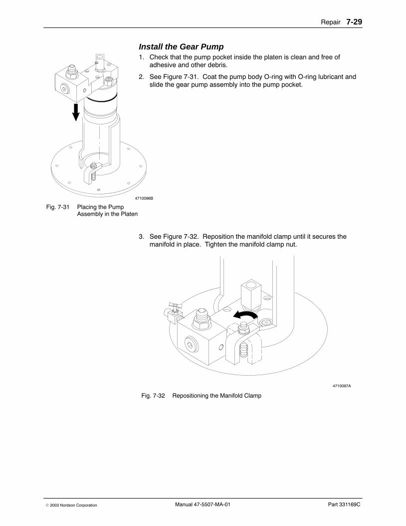
4710096B
Repair 7-29
Part 331169C� 2003 Nordson Corporation Manual 47-5507-MA-01
Install the Gear Pump1. Check that the pump pocket inside the platen is clean and free of
adhesive and other debris.
2. See Figure 7-31. Coat the pump body O-ring with O-ring lubricant andslide the gear pump assembly into the pump pocket.
Fig. 7-31 Placing the PumpAssembly in the Platen
3. See Figure 7-32. Reposition the manifold clamp until it secures themanifold in place. Tighten the manifold clamp nut.
4710097A
Fig. 7-32 Repositioning the Manifold Clamp

4710131B
Repair7-30
Part 331169C � 2003 Nordson CorporationManual 47-5507-MA-01
Install the Gear Pump(contd)4. See Figure 7-33. Position the universal joint so that the lower yoke
assembly can be slid onto the bottom of the driveshaft. Lower the yokeassembly onto the pump shaft and tighten with the set screw.
4710163AA B C
Fig. 7-33 Attaching the Lower Yoke Assembly to the Driveshaft
5. See Figure 7-34. Reinstall the hose(s) onto the connector(s) at thepump manifold.
6. Close the manifold drain valve.
Fig. 7-34 Installing the Hose on theManifold

4710108A
Repair 7-31
Part 331169C� 2003 Nordson Corporation Manual 47-5507-MA-01
7. See Figure 7-35. Loosen the two round head screws and machine hexnuts that secure the column collar in place. Slide the collar down until itseats on the follower plate across the drive shaft-to-pump connection.Tighten the round head screws and hex nuts to secure the collar inplace.
8. Set the main disconnect switch to the ON position and press thePOWER ON button.
9. Bring the unit to application temperature. Lower the platen into the drumof material as described in the Drum Changeout procedure in theOperation section and resume normal operation.
Fig. 7-35 Lowering the ColumnCollar
Drive Assembly Use the following procedures to repair and replace components of the drummelter/applicator’s drive assembly.
Inspect and Replace the Drive Motor Brushes Except for the motor brush, the drive motor is not field-repairable and canonly be replaced as described in Replacing the Drive Motor in this section.
Use the following procedure to inspect and replace the drive motor brush.
You will need a device for measuring brush length to complete thisprocedure. If the brushes are worn, you will need new motor brushes (referto the Parts section for the part number).
1. Press the STOP button on the electrical enclosure front panel and setthe main disconnect switch to the OFF position.
2. Lock out input power to the unit.

Repair7-32
Part 331169C � 2003 Nordson CorporationManual 47-5507-MA-01
Inspect and Replace the Drive Motor Brushes (contd)
3. Remove the cover plates on both sides of the motor housing that securethe drive motor brushes in place.
4. Use a small screwdriver or similar tool to carefully pry the brushretaining spring up and free of its brush.
NOTE: Note the orientation of the brush with respect to any identifyingfeatures (notch or slanted pressure pad, for example). Useneedle-nose pliers or a similar tool to carefully pull the brush out of itsholder and inspect it.
5. Measure the brush length. Replace the brushes if they are shorter than25.4 mm (1.00 in.).
6. Install the old/new brushes (noting any identifying features to assist withorientation) and reposition the retaining springs over the brushes.
7. Replace the cover plates and resume normal operation.
Replace the Drive Motor If a clutch is installed on the unit, refer to the Drive Motor/Clutch AssemblyReplacement procedure in this section.
Use the following procedure to replace the drive motor. Have a liftingdevice certified to lift 27 kg (60 lb) available to complete this procedure.
Remove the Drive Motor1. Press the STOP button on the electrical enclosure front panel, set the
main disconnect switch to the OFF position, and lock out input power tothe unit.
2. Remove the junction box cover and disconnect the motor leads.
3. Disconnect the motor conduit connector at the junction box.
4. Secure the lifting device to the motor.

Repair 7-33
Part 331169C� 2003 Nordson Corporation Manual 47-5507-MA-01
5. See Figure 7-36. Remove the four hex head screws and splitlockwashers (2) that secure the motor (5) to the speed reducer (3).
4756588A
1 25
3
4
Fig. 7-36 Drive Assembly Details
1. Clutch2. Motor/Speed reducer screws and
washers (Clutch/Speed reducerscrews and washers on unit withoptional clutch shown)
3. Speed reducer4. Speed reducer/Crossover screws
and washers5. Motor
6. Lift the motor free of the unit while carefully guiding the motor leads freeof the junction box.
Install the New Drive Motor1. Secure the lifting device to the replacement motor and lower the motor
until it is aligned with the speed reducer.
2. Align the motor keyway with the speed reducer keyway and install thekey.
3. Replace the four hex head screws and split lockwashers that secure themotor to the speed reducer.
4. Reconnect the motor conduit connector at the junction box.
5. Reconnect the motor leads. Wire 44B connects to motor terminal A1and wire 45B connects to motor terminal A2.
6. Restore input power to the unit, set the main disconnect switch to theON position, press the POWER ON button, and resume normaloperation.

Repair7-34
Part 331169C � 2003 Nordson CorporationManual 47-5507-MA-01
Replace the Drive Motor/Clutch Assembly The clutch is not field-repairable and can only be replaced.
Use the following procedure to replace the drive motor and clutch assembly.Have a lifting device certified to lift 32 kg (70 lb) available to complete thisprocedure.
Remove the Drive Motor/Clutch Assembly1. Press the STOP button on the electrical enclosure front panel, set the
main disconnect switch to the OFF position, and lock out input power tothe unit.
2. Remove the junction box cover and disconnect clutch leads 78B and 79from the power supply.
3. Disconnect the motor leads.
4. Disconnect the clutch conduit connector and motor conduit connector.
5. Secure the lifting device to the motor/clutch assembly.
6. See Figure 7-36. Remove the four hex head screws and splitlockwashers (2) that secure the clutch (1) to the speed reducer (3).Remove the key from the clutch/speed reducer keyway.
7. Lift the motor/clutch assembly free of the unit while carefully guiding theclutch and motor leads free of the junction box.
8. To separate the drive motor from the clutch, remove the four hex headscrews and split lockwashers that secure the drive motor to the clutch.Remove the key from the motor/clutch keyway.

Repair 7-35
Part 331169C� 2003 Nordson Corporation Manual 47-5507-MA-01
Install the New Drive Motor/Clutch Assembly1. Secure the replacement clutch to the drive motor and reinstall the key in
the motor/clutch keyway.
2. Replace the four hex head screws and split lockwashers that connectthe clutch to the drive motor.
3. Secure the lifting device onto the motor/clutch assembly and lower theassembly onto the speed reducer.
4. Replace the key in the clutch/speed reducer keyway and replace thefour hex head screws and split lockwashers that connect the clutch tothe speed reducer.
5. Reconnect the clutch conduit connector and motor conduit connector atthe junction box.
6. Reconnect the motor leads inside the junction box. Wire 44B connectsto motor terminal A1 and wire 45B connects to motor terminal A2.
7. Reconnect the clutch leads inside the junction box. Wire 78B connectsto terminal YC-3 and wire 79 connects to terminal YC-6 on the clutchpower supply socket.
8. Replace the junction box cover.
9. Restore input power to the unit, set the main disconnect switch to theON position, press the POWER ON button, and resume normaloperation.
Replace the Speed Reducer The speed reducer is not field-repairable and can only be replaced.
Use the following procedure to replace the speed reducer. Have a liftingdevice certified for at least 27 kg (60 lb), and a flat head screwdriveravailable to complete this procedure.

Repair7-36
Part 331169C � 2003 Nordson CorporationManual 47-5507-MA-01
Remove the Speed Reducer1. Press the STOP button on the electrical enclosure front panel, set the
main disconnect switch to the OFF position, and lock out input power tothe unit.
2. Remove the drive motor or drive motor/clutch assembly as described inthis section.
3. Secure the lifting device to the speed reducer.
4. Remove the hex head screws and split lockwashers that secure thespeed reducer to the crossover.
5. See Figure 7-37. Lift the speed reducer until the upper yoke assemblyis visible.
4710175B
Fig. 7-37 Lifting the Speed Reducer to Access the Upper Yoke Assembly

Repair 7-37
Part 331169C� 2003 Nordson Corporation Manual 47-5507-MA-01
6. Secure the drive shaft/yoke assembly in place by sliding a screwdriverthrough the yoke to prevent the drive shaft from dropping down into thecolumn. The drive shaft will slide out of the lower yoke assembly whichis coupled to the gear pump.
7. See Figures 7-38 and 7-39. Loosen the set screws in the upper yokeassembly and lift the speed reducer free of the unit.
4710176B
Fig. 7-38 Loosening the Upper Yoke Assembly Set Screws
4710178B
Fig. 7-39 Lifting the Speed Reducer from the Unit

Repair7-38
Part 331169C � 2003 Nordson CorporationManual 47-5507-MA-01
Install the New Speed Reducer1. Secure the lifting device to the replacement speed reducer and lower
the speed reducer onto the unit.
2. See Figure 7-38. Tighten the set screws in the upper yoke assemblyonto the speed reducer output shaft.
3. Remove the screwdriver and lower the speed reducer until it seats onthe crossover. Check that the driveshaft is inserted in the lower yokeassembly.
4. Replace the hex head screws and split lockwashers that secure thespeed reducer to the crossover.
5. Remove the lifting device from the speed reducer.
6. Reinstall the drive motor or motor/clutch assembly as described in thissection.
7. Restore input power to the unit, set the main disconnect switch to theON position, press the POWER ON button, and resume normaloperation.
Pneumatic System Use the following procedures to repair and replace components of the drummelter/applicator’s pneumatic system.
Rebuild the Air Cylinder Assembly Use the following procedure to rebuild an air cylinder(s). The followingitems are required to complete this procedure:
� A piece of plywood or other heat-resistant material slightly larger thanthe platen diameter
� A spanner or similar tool
� A lifting device certified to lift 136 kg (500 lb)
� Snap-ring pliers
� A pair of cylinder head V-block packings
� A pair of cylinder head O-rings
� A pair of piston O-rings
� A pair of piston seals
� A pair of piston wear rings
� Thread locking adhesive
� Parker O-ring Lubricant
� Petroleum jelly
� Cylinder head assembly
� Air cylinder shaft
� Spacer

Repair 7-39
Part 331169C� 2003 Nordson Corporation Manual 47-5507-MA-01
Remove the Air Cylinder Assembly1. If a drum of material is installed on the unit, remove it as described in
the Drum Changeout procedure in the Operation section.
2. Place the piece of heat-resistant material on the frame (or across thedrum hold-down assembly) under the platen.
3. Use the elevator control valve to lower the platen onto the heat-resistantmaterial.
4. Press the STOP button on the electrical enclosure front panel, set themain disconnect switch to the OFF position, and lock out input electricalpower to the unit.
5. Disconnect the input air supply from the unit.
6. Set the elevator control valve to the UP position to vent residual airpressure from above the air pistons. Then place the elevator controlvalve in the DOWN position as a fail-safe to vent any remaining airpressure from below the air pistons. Set the elevator control valve to thecenter position.
7. See Figure 7-40. Using the spanner or a similar tool to keep the aircylinder shafts stationary, remove the hex head screws and splitlockwashers that secure the crossover in place.
4710346A
Fig. 7-40 Removing the Screws and Washers from the Crossover

Repair7-40
Part 331169C � 2003 Nordson CorporationManual 47-5507-MA-01
Remove the Air Cylinder Assembly(contd)8. Secure the lifting device to the crossover. Lift the crossover and rotate it
enough to provide access to the air cylinder assembly.
CAUTION: Failure to observe and follow this procedure may result inpersonal injury or equipment damage.
9. Secure the crossover to prevent it from falling or interfering with yourwork in the air cylinder.
10. See Figure 7-41. Remove the cylinder head assembly by compressingthe internal retaining ring with a pair of snap-ring pliers and lifting theassembly out of the air cylinder.
4710315
A B
Fig. 7-41 Removing the Cylinder Head Assembly
CAUTION: Do not bend, scratch, or otherwise damage the air cylindershaft when performing the following step.
11. Carefully pull the air cylinder shaft straight up and out of the air cylinder.A piston assembly is attached to the bottom of the shaft.

Repair 7-41
Part 331169C� 2003 Nordson Corporation Manual 47-5507-MA-01
Rebuild the Air Cylinder Assembly1. See Figure 7-42. Remove the V-block packing (2) and Bona O-ring (1)
from the cylinder head (3). Clean the cylinder head surfaces andgrooves thoroughly.
4710311
1
2
3
Fig. 7-42 Removing the O-ring and Packing from the Cylinder Head
1. O-ring2. V-block packing
3. Cylinder head
2. Inspect the cylinder head for damage. If damaged, replace the entirecylinder head assembly, including the O-ring and packing. If it is notdamaged, replace only the O-ring and packing.
3. See Figure 7-43. Remove the hex head screw (4), washer (2), and splitlockwasher (3) that secures the piston assembly (1) to the air cylindershaft.
4710312
ÎÎÎÎÎÎ
1
2
3
4
Fig. 7-43 Removing the Piston Assembly from the Shaft
1. Piston assembly2. Washer
3. Split lockwasher4. Hex head screw
4. Remove the wear rings, piston seals, and Buna O-rings from the piston.Clean the piston surfaces and grooves thoroughly.
5. Remove the piston spacer from the end of the air cylinder shaft.
6. Inspect the interior surfaces of the air cylinder for nicks, scratches orother damage. If the cylinder is damaged, contact your Nordsonrepresentative for further advice on replacement or repair.

Repair7-42
Part 331169C � 2003 Nordson CorporationManual 47-5507-MA-01
Rebuild the Air Cylinder Assembly(contd)7. Inspect the air cylinder shaft for nicks, scratches, bending, or other
damage. If damaged, replace the shaft.
8. See Figure 7-44. Orient the air cylinder shaft with the spanner hole atthe top. The spanner hole is 10.8 cm (4.25 in.) from the top of the shaft.
9. Inspect the spacer for damage. If damaged, replace the spacer.
10. Slide the spacer onto the piston end of the shaft.
11. Install a new Buna O-ring on the piston.
4701162A
10.8 cm(4.25 in.)
Fig. 7-44 Air Cylinder Shaft Orientation
CAUTION: The Buna O-ring must be installed before the seal or wear ring.Failure to observe and follow this procedure may result in a faulty seal andpoor operation.
12. Install a new seal and wear ring on the piston.
13. Coat the threads of the hex head screw with thread locking adhesive.Secure a piston to the bottom of the air cylinder shaft with the hex headscrew, washer, and split lockwasher.
14. Apply O-ring Lubricant to the inside surfaces of the air cylinder wall.
15. Coat the air cylinder shaft with petroleum jelly.

Repair 7-43
Part 331169C� 2003 Nordson Corporation Manual 47-5507-MA-01
Install the Air Cylinder Assembly1. Insert the shaft with attached piston assembly into the air cylinder. Do
not bend, scratch, or otherwise damage the shaft.
2. Guide the shaft to the bottom of the cylinder.
3. See Figure 7-45. Place the retaining ring in its groove on the cylinderhead assembly.
4710313
A B
Fig. 7-45 Installing the Retaining Ring on the Cylinder Head Assembly
4. See Figure 7-46. Using the snap-ring pliers, compress the retaining ringand install the cylinder head assembly into the top of the air cylinder.
4710316A BFig. 7-46 Installing the Cylinder Head Assembly in the Air Cylinder

Repair7-44
Part 331169C � 2003 Nordson CorporationManual 47-5507-MA-01
Install the Air Cylinder Assembly(contd)5. Rotate the crossover into position over the air cylinder shafts. Lower the
crossover onto the air cylinder shafts.
6. See Figure 7-40. With the washers in place, hand thread the hex headscrews that secure the crossover to the air cylinder shafts.
7. Using the spanner or similar tool to keep the air cylinder shaftsstationary, tighten the hex head screws.
8. Remove the lifting equipment.
9. Restore input air pressure to the unit.
10. Restore input power to the unit, set the main disconnect switch to theON position, and press the POWER ON button.
11. Check for proper operation of the platen elevator.
12. Install a drum of material on the unit, as described in the DrumChangeout procedure in the Operation section and resume normaloperation.

SE
CT
ION
8
## TABSHEET ##

Parts 8-1
Part 331169C� 2003 Nordson Corporation Manual 47-5507-MA-01
Section 8Parts
Introduction To order parts, call the Nordson Customer Service Center or your localNordson representative. Use this five-column parts list, and theaccompanying illustration, to describe and locate parts correctly.
Using the Illustrated Parts List Numbers in the Item column correspond to numbers that identify parts inillustrations following each parts list. The code NS (not shown) indicatesthat a listed part is not illustrated. A dash (—) is used when the part numberapplies to all parts in the illustration.
The number in the Part column is the Nordson Corporation part number. Aseries of dashes in this column (- - - - - -) means the part cannot be orderedseparately.
The Description column gives the part name, as well as its dimensions andother characteristics when appropriate. Indentions show the relationshipsbetween assemblies, subassemblies, and parts.
� If you order the assembly, items 1 and 2 will be included.
� If you order item 1, item 2 will be included.
� If you order item 2, you will receive item 2 only.
The number in the Quantity column is the quantity required per unit,assembly, or subassembly. The code AR (As Required) is used if the partnumber is a bulk item ordered in quantities or if the quantity per assemblydepends on the product version or model.
Letters in the Note column refer to notes at the end of each parts list. Notescontain important information about usage and ordering. Special attentionshould be given to notes.
Item Part Description Quantity Note— 0000000 Assembly 11 000000 � Subassembly 2 A2 000000 � � Part 1

Parts8-2
Part 331169C � 2003 Nordson CorporationManual 47-5507-MA-01
Illustrated Parts List The following parts lists include the assemblies and subassemblies of theModel 5507 drum melter/applicator.
Crossover Assembly See Figure 8-1.
Item Part Description Quantity Note— - - - - - - Crossover assembly 11 274 830 � Grommet, neoprene, 0.250 in. thick 12 - - - - - - � Assembly, junction box 1 A3 326 834 � Crossover, painted, 5507 14 982 134 � Screw, hex head, M6 x 14, cap 45 983 040 � Washer, flat, 0.266 x 0.625 x 0.049 in. 46 981 551 � Screw, hex head, 7/8−14 x 1.125 in., cap 27 983 501 � Washer, lock, split, 7/8, zinc 28 107 521 � Cap, end, 4 in. square, plastisol 29 - - - - - - � Assembly, frame, 55 gallon 1 A10 324 253 � Conduit, formed, 3/411 984 715 � Nut, Hex, machine, M4 212 982 124 � Screw, pan, M4 x 20 213 271 796 � Collar, column, painted 114 272 059 � Connector, 3/4, compression 415 272 058 � Seal, conduit fitting, 3/4 416 803 877 � Assembly, harness 117 324 896 � Grommet, rubber, 0.812 ID x 1.250 in. OD 218 106 506 � Kit, instruction 119 324 391 � Clip, wire, molded nylon, 0.750 in. diameter 120 172 392 � Plate, retaining, rod 221 982 160 � Screw, socket, M8 x 25 822 983 414 � Washer, flat, narrow, M8 823 983 404 � Washer, lock, split, M8 8NS 900 464 � Adhesive, thread locking —NS 900 422 � Adhesive, bonding, instant —NS 900 222 � Paint, touch-up, Nordson blue —
NOTE A: See separate parts lists.
NS: Not Shown

Parts 8-3
Part 331169C� 2003 Nordson Corporation Manual 47-5507-MA-01
4701163A
6, 7
10
8
1 2
9
11, 12
1317
14, 15
3
16
4, 5
18
19
ÇÇÇÇÇÇÇ
ÇÇÇÇÇÇÇÇÇÇÇÇÇÇ
ÉÉÉÉÉ
21, 22, 23
20
Fig. 8-1 Crossover Assembly

Parts8-4
Part 331169C � 2003 Nordson CorporationManual 47-5507-MA-01
Frame Assembly See Figure 8-2.
Item Part Description Quantity Note— - - - - - - Frame assembly 11 933 079 � Connector, conduit 22 803 819 � Conduit, flex, bulk, 3/8 AR3 272 077 � Bracket, switch, painted 14 981 402 � Screw, hex head, 3/8-16 x 1.00, cap 15 983 160 � Washer, lock, split, 3/8 16 986 306 � Retaining ring, interior, 650, basic 27 271 780 � Assembly, cylinder head 28 - - - - - - � � Head, cylinder 19 271 777 � � Packing, block vee, 2.00 in. ID 110 271 778 � � Scraper, wiper, 2.00 in. ID 111 - - - - - - � � Bushing, 2.00 ID x 2.38 OD x 1.50 in. 112 942 560 � � O-ring, buna N, 5.75 x 6.00 x 0.125 in. 113 271 800 � Shaft, air cylinder 214 271 775 � Spacer, 2.25 ID x 3.00 OD x 4.00 in. 215 271 774 � Ring, wear, 6.00 in. OD 216 981 552 � Screw, hex head, 7/8-14 x 2.25 in., cap 217 983 501 � Washer, lock, split, 7/8 218 271 776 � Seal, piston 219 942 560 � O-ring, buna N, 5.75 x 6.00 x 0.125 in. 220 271 781 � Piston 221 973 411 � Plug, pipe, socket, flush, 1/4 222 271 487 � Cap, end, vinyl 123 981 160 � Screw, pan, 10-32 x 0.500 224 983 120 � Washer, lock, split, #10 225 112 323 � Actuator, limit switch w/ tip 1 A26 939 813 � Switch, limit, heavy duty 1 A27 - - - - - - � Frame, drum, 5000 128 971 160 � Elbow, male, hydraulic, 1/4 T x 1/4 NP 1NS 900 464 � Adhesive, thread locking —NS 900 223 � Lubricant, O-ring, Parker —
NOTE A: These parts are included in the limit switch repair kit, part 162 766.
NS: Not Shown
AR: As Required

Parts 8-5
Part 331169C� 2003 Nordson Corporation Manual 47-5507-MA-01
4701164
27
22, 23, 24,
21
ÉÉÉÉÉÉÉÉÉÉÉÉÉÉÉÉ
ÉÉÉÉÉÉÉÉÉÉÉÉÉÉÉÉ
12
8 9 10
11
ÇÇÇÇ
ÇÇÉÉÉ
ÉÉÉ
ÇÇ
ÉÉ
ÉÉ
6
7
13
14
15
16, 17
20
18, 19
1
2
3, 4, 5
A
A
25, 26
28
9
8
Fig. 8-2 Frame Assembly

Parts8-6
Part 331169C � 2003 Nordson CorporationManual 47-5507-MA-01
Drive Assembly See Figure 8-3.
Item Part Description Quantity Note— - - - - - - Drive assembly 11 939 122 � Seal, conduit fitting, 1/2 12 933 079 � Connector, conduit 23 933 077 � Conduit, flex, bulk, 3/8 AR4 324 725 � Motor, electric, 1 hp, model 5530 15 983 405 � Washer, lock, split, M10 86 984 172 � Nut, hex head, lock, 1/2-13 UNC-2B 17 982 006 � Screw, socket, M8 x 20 28 981 408 � Screw, hex head, 3/8-16 x 1.250 in., cap 49 229 694 � Reducer, speed, worm gear, 10:1 110 982 478 � Screw, hex head, M10 x 30, cap 411 324 019 � Assembly, shaft, drive, 55 gallon 112 983 404 � Washer, lock, split, M8 213 274 307 � Pivot, tube, hose support 114 274 174 � Hanger, hose, 5/8 in. ID and 1-1/8 in. ID 115 274 305 � Arm, support, hanger, welded 1NS 900 236 � Sealant, paste —
AR: As Required
NS: Not Shown

Parts 8-7
Part 331169C� 2003 Nordson Corporation Manual 47-5507-MA-01
4701165
1, 2
9
11
2
8, 5
10, 5
4
3
15
14
13
7, 12
6
A
A
VIEW A
Fig. 8-3 Drive Assembly

Parts8-8
Part 331169C � 2003 Nordson CorporationManual 47-5507-MA-01
Pump Assembly See Figure 8-4.
Item Part Part Part Description Quantity Note— 333 720 — — Pump assembly, 3/4 gerotor, 1200 psi
(5/16 in. ID Hose)—
— — 333 720 — Pump Assembly, 3/4 gerotor, 1200 psi(5/8 in. ID Hose)
—
— — — 333 719 Pump Assembly, 3/4 gerotor, 1000 psi(1 1/8 in. ID Hose)
—
1 274 312 274 312 274 312 � Body, pump 12 942 371 942 371 942 371 � O-ring, Viton, 3.375 x 3.625 x 0.125 in. 13 271 916 271 916 271 916 � Plate, pump, upper 14 271 889 271 889 271 889 � Retainer, gerotor, 0.750 in. thick 15 271 917 271 917 271 917 � Plate, pump, lower 16 981 557 981 557 981 557 � Screw, socket head, 1/4-20 x 1.750 in. 67 981 233 981 233 981 233 � Screw, socket head, 1/4-20 x 1.000 in. 28 271 888 271 888 271 888 � Gerotor set, 6-tooth, 0.750 in. thick 19 172 326 172 326 172 326 � Shaft, pump, 750 gerotor 110 272 045 272 045 272 044 � Valve, relief, pressure 111 945 025 945 025 945 025 � � O-ring, Viton, 0.755 x 0.970 in. 112 940 141 940 141 940 141 � � O-ring, Viton, 0.500 x 0.625 x 0.063 in. 113 236 366 236 366 236 366 � Seal, shaft, 0.625 x 0.875 in. 214 274 300 274 300 274 300 � Bearing, needle, open, 0.625 in. 215 168 054 168 054 168 054 � Key, woodruff, #3, hardened 116 236 365 236 365 236 365 � Seal, shaft, 0.625 x 0.812 in. 117 167 002 167 002 � Manifold, pump, single hose, (5/16 and
5/8 in. ID)1
17 272 042 272 042 � Manifold, pump, dual hose, (5/16 and5/8 in. ID)
1
17 272 043 � Manifold, pump, single hose, (1 1/8 in. ID) 117 115 878 � Manifold, pump, dual hose, (1 1/8 in. ID) 118 236 348 236 348 236 348 � Bearing, needle, closed, 0.625 in. 119 986 310 986 310 986 310 � Retaining ring, internal, 84, spiral 120 940 201 940 201 940 201 � O-ring, Viton, 0.864 x 0.070 in. 121 981 101 981 101 981 101 � Screw, socket set, 10-32 x 0.187, cup 122 178 170 178 170 178 170 � Key, 1/8 x 1/8 x 0.800 in. 123 973 431 973 431 973 431 � Plug, pipe, 1/2 npt 1 A24 271 884 271 884 271 884 � Valve, manual, 1/4 npt 125 972 619 � Connector, male, 37 in., 9/16-18 x 1/2 npt
(5/16 in. ID)1 A
25 972 620 � Connector, male, 37 in., 1 1/16-12 x 1/2 npt(5/8 in. ID)
1 A
25 972 621 � Connector, male, 37 in., 1 5/8-12 x 1 1/4 npt(1 1/8 in. ID)
1
25 803 536 � Connector, male, 37 in., 1 5/8-12 x 1 npt(1 1/8 in. ID
2
Continued...

Parts 8-9
Part 331169C� 2003 Nordson Corporation Manual 47-5507-MA-01
Item Part Part Part Description Quantity Note26 981 556 981 556 981 556 � Screw, socket head, 1/4-20 x 1.50 in. 327 172 328 172 328 172 328 � Block, coupling, shaft, 1.250 in. long 128 272 046 272 046 272 046 � Washer, bearing, 0.620 x 0.960 x 0.062 in. 129 973 402 973 402 973 402 � Plug, pipe, 1/8 nptf (single hose units only) 1NS 900 236 900 236 900 236 � Sealant, paste —NS 900 318 900 318 900 318 � Grease, flourinated, 2 oz. —NS 902 504 902 504 902 504 � Tape —
NOTE A: Two of these parts are enclosed with the dual hose manifold and pump assembly.
AR: As Required
NS: Not Shown
4701167
22
21
27
2625
24 28
17
23 29
13
1420
10
11
12
1
2
14
13
3
4
8
7
915
19
16
5
18
6
Fig. 8-4 Pump Assembly

Parts8-10
Part 331169C � 2003 Nordson CorporationManual 47-5507-MA-01
Platen Assembly See Figure 8-5.
Item Part Description Quantity Note— - - - - - - Platen assembly 11 326 813 � Platen 12 - - - - - - � RTD, nickel, tip, 0.250 x 5.00 in. 1 A3 326 809 � Plate, cover, seam 24 326 810 � Gasket, cover, seam 25 326 791 � Cover, platen, front 16 326 792 � Cover, platen, rear 17 185 377 � Tube, Viton, seal, platen cvr 9 ft8 272 279 � Connector, temp sensor, 1/4 19 - - - - - - � Tag, warning, disconnect power 110 981 905 � Screw, drive, round, 2 x 0.187 in. 211 272 069 � Clamp, Manifold 112 984 707 � Nut, hex, regular, M8 113 983 404 � Washer, lock, split, M8 114 185 376 � Stud, M8 x 75 115 272 068 � Spring, Comp, 2.000 x 0.328 ID x 0.042 in. 116 125 112 � Nut, hex, jam, M8 117 981 528 � Screw, socket, M8 x 30 818 982 134 � Screw, hex, cap, M6 x 14 2319 983 410 � Washer, flat, narrow, M6 2320 983 013 � Washer, flat, regular, M8 221 - - - - - - � Seal, platen 1 ANS 275 386 � Compound, thermal joint —NS 982 261 � Screw, pan, rec, M3.5 x 10 1 BNS 226 831 � Washer, flat, M3.5 1 BNS 983 424 � Washer, split lock, M3.5 1 BNS 900 413 � Sealant, RTV, red —
�
�
NOTE A: Specific part numbers are given in the table of recommended spare parts.
B: Used to secure ground wire.
NS: Not Shown

Parts 8-11
Part 331169C� 2003 Nordson Corporation Manual 47-5507-MA-01
4701196A
18, 19
6
5
17, 13
10
17, 13, 20
1
4
3
7
14
13, 12
16
8
2
11 15
9
21
VIEW B
VIEW C
VIEW C
VIEW BVIEW B
17, 13
Fig. 8-5 Platen Assembly

Parts8-12
Part 331169C � 2003 Nordson CorporationManual 47-5507-MA-01
Junction Box Assembly See Figure 8-6.
Item Part Description Quantity Note— - - - - - - Junction box 11 324 344 � Assembly, cover, junction box w/ tag 12 981 428 � � Screw, captive, 10-32 x 0.432 in. 23 983 122 � � Washer, retainer, #10 2
NS 242 654 � � Gasket, cabinet 4 ft4 324 357 � � Cover, junction box, painted 15 981 020 � Screw, pan, 6-32 x 0.250 in. 26 983 100 � Washer, lock, interior, #6 27 324 608 � Block, terminal, modular, 12-station 18 939 355 � Socket, relay, 8-pin 19 984 101 � Nut, hex, machine, 6-32 410 933 281 � Block, terminal, 4-station 111 324 358 � Junction box, crossover, painted 112 983 120 � Washer, lock, split, #10 213 984 129 � Nut, hex, machine, 10-32, brass 314 271 221 � Lug, 45, double, 0.250 in., 0.438 in. 315 240 674 � Tag. Ground 1
NS: Not Shown
4701170
11
7
2
4
8
3
10
5, 6
9
1
14
1213
15
Fig. 8-6 Junction Box Assembly

Parts 8-13
Part 331169C� 2003 Nordson Corporation Manual 47-5507-MA-01
Basic Electrical Enclosure Assembly (Outside) See Figures 8-7.
Item Part Description Quantity Note— - - - - - - Basic electrical enclosure assembly 11 939 359 � Light, pilot, 120 volt, amber 12 324 309 � Plate, legend, low drum 13 939 331 � Light, pilot, 120 volt, red 14 324 308 � Plate, legend, over-temperature 15 939 811 � Button, push, illuminated, guarded 16 324 306 � Plate, legend, power on 17 939 353 � Switch, push button, stop 18 - - - - - - � Plate, legend, e-stop 19 939 812 � Switch, selector, illuminated, 2-position 110 324 311 � Plate, legend, pump on/off 111 - - - - - - � Tag, warning, disconnect power 119 981 022 � Screw, filister, 6-32 x 0.375 in. 820 983 100 � Washer, lock, interior, #6 821 324 327 � Mechanism, handle, disconnect 124 324 328 � Handle assembly, door 125 324 355 � Cabinet, electrical, painted 126 119 030 � Heatsink, machined, electrical box 127 939 644 � Triac, tank, control, 25 am 228 271 221 � Lug, 45, double, 0.250 in., 0.438 in. 429 984 129 � Nut, hex, machine, 10-32, brass 530 983 120 � Washer, lock, split, #10 533 240 674 � Tag, ground 234 136 418 � Name plate, Nordson oval 135 984 529 � Nut, spring, push on. 0.125 in. 337 985 111 � Rivet, blind, 3/32 x 0.125, aluminum 438 - - - - - - � Plate, on/off main breaker 139 335 176 � Clamp, cable, ribbon, 3 in. maximum 150 939 637 � Connector, conduit 151 274 385 � Seal, conduit fitting, 1 1/4 in. 155 981 544 � Screw, socket head, 6-32 x 0.500 1056 - - - - - - � Wire group, basic LCU 158 156 408 � Lock bar, lower 161 156 407 � Lock bar, upper 1NS 275 386 � Compound, thermal joint, 2 oz. —
NS: Not Shown

Parts8-14
Part 331169C � 2003 Nordson CorporationManual 47-5507-MA-01
Basic Electrical Enclosure Assembly (Outside) (contd)
4701171A
POWER ON
OVER−TEMP
LOW DRUM
STOP
PUMP
OFF/ON
ON
OFF
25
38
21
11, 37
24, 58, 6134, 35
5, 63, 456
50, 51
1, 2
7, 8 9, 10(SEE DOORINTERIOR)
DETAIL B(DOOR GROUND STUD)
33
2928
30
39
SECTION B(INSIDE ENCLOSURE)
19, 20, 2726
55
SECTION A(HEAT SINK)
A
A
B
B
CH 1
CH 2
CH 3
CH 4
CH 5
SENSORFAULT
PLATEN
Fig. 8-7 Basic Electrical Enclosure Assembly (Outside)

Parts 8-15
Part 331169C� 2003 Nordson Corporation Manual 47-5507-MA-01
Basic Electrical Enclosure Assembly (Inside) See Figures 8-8.
Item Part Description Quantity Note— - - - - - - Basic electrical enclosure assembly 112 271 964 � Duct, wire, 14-in. 113 981 064 � Screw, pan, 8-32 x 0.375 714 324 335 � Contactor, main power 115 983 011 � Washer, lock, interior, #8 716 939 020 � Fuse, 30.00, fast-acting, 600 volt 217 939 509 � Fuse, 5.00, time-delay, 250 volt 118 939 762 � Fuse block, 8-pole 119 981 022 � Screw, filister, 6-32 x 0.375 in. 820 983 100 � Washer, lock, interior, #6 822 324 354 � Panel, inner, electrical enclosure, painted 123 324 336 � Block, terminal, electrical box 128 271 221 � Lug, 45, double, 0.250 in., 0.438 in. 429 984 129 � Nut, hex, machine, 10-32, brass 530 983 120 � Washer, lock, split, #10 531 981 156 � Screw, pan, 10-32 x 1.000 in., brass 132 939 488 � Terminal, wire, ground 133 240 674 � Tag, ground 235 984 529 � Nut, spring, push on. 0.125 in. 336 272 620 � Suppressor, arc, w/ terminals 140 933 397 � Gasket, base, connector 241 933 392 � Base, connector, panel mount 142 933 395 � Insert, connector, receptacle 143 981 029 � Screw, filister, 6-32 x 0.500 in. 844 984 101 � Nut, hex, machine, 6-32 845 983 102 � Washer, lock, split, #6 846 324 252 � Plate, cover, connector cut-out 147 324 442 � Standoff, 10-32 m/f x 3.00 in. long 148 981 160 � Screw, pan, 10-32 x 0.500 249 939 528 � Socket, crimp contact 1652 933 396 � Receptacle cover 153 242 837 � Mount, cable strap 254 939 295 � Fuse, 8.00, time-delay, 250 volt 257 939 827 � Block, fuse 159 984 152 � Nut, hex, 3/8-16 460 983 160 � Washer, lock, 3/8 461 816 243 � Fuse, 1.50, time delay, 500 volt 1 A
NOTE A: Fuse is required for 380 volt and 415 volt units only.
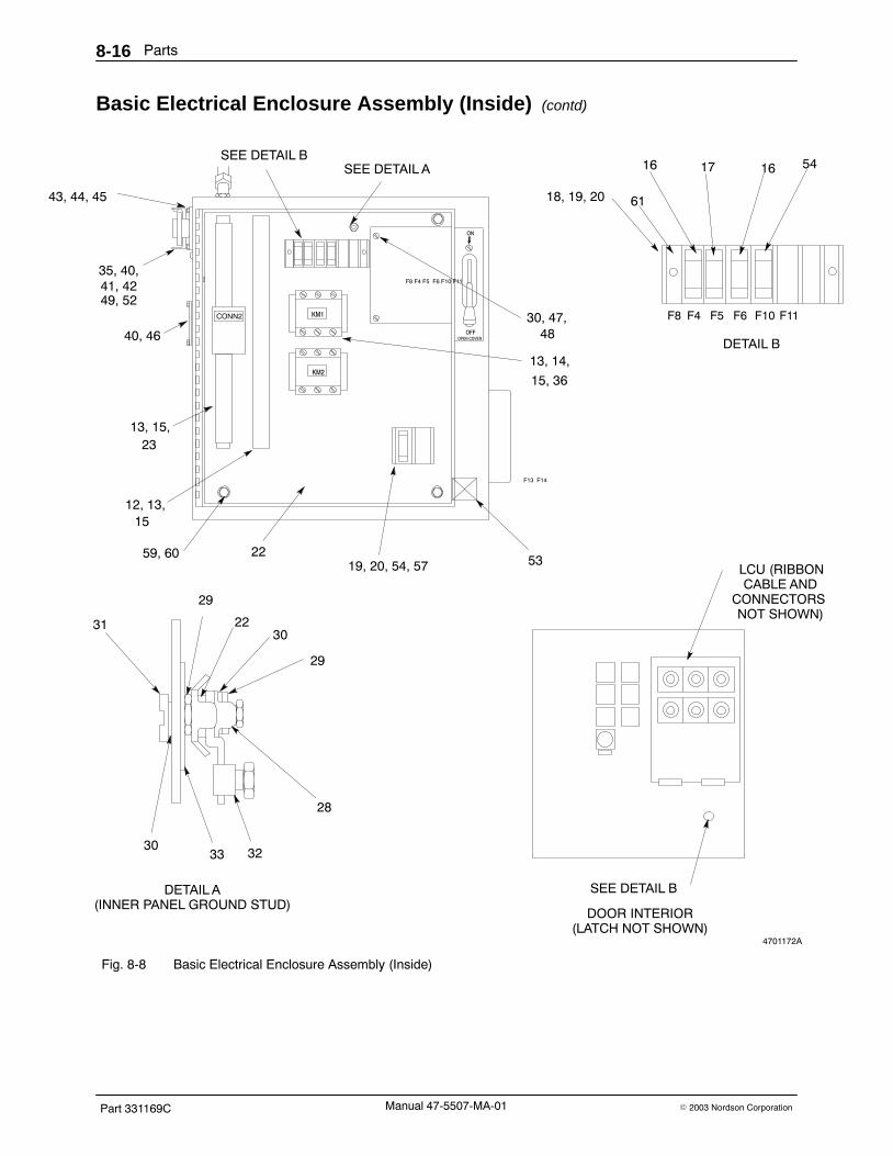
Parts8-16
Part 331169C � 2003 Nordson CorporationManual 47-5507-MA-01
Basic Electrical Enclosure Assembly (Inside) (contd)
4701172A
OFFOPEN COVER
ON
53
12, 13,
22
]
13, 15,
40, 46
35, 40,
30, 47,
13, 14,
15
23
41, 42
48
15, 36
49, 52
LCU (RIBBONCABLE AND
CONNECTORS NOT SHOWN)
SEE DETAIL B
31 2230
29
29
30
28
33 32
SEE DETAIL A
DETAIL A(INNER PANEL GROUND STUD)
19, 20, 54, 57
DOOR INTERIOR(LATCH NOT SHOWN)
43, 44, 45
59, 60
F8 F4 F5 F6 F10 F11
F13 F14
KM2
KM1 F8
18, 19, 20
16 17 5416
61
SEE DETAIL B
F5 F6 F10 F11F4
DETAIL B
Fig. 8-8 Basic Electrical Enclosure Assembly (Inside)

Parts 8-17
Part 331169C� 2003 Nordson Corporation Manual 47-5507-MA-01
Electrical Kit See Figure 8-9.
Item Part Description Quantity Note— - - - - - - Electrical kit 11 - - - - - - � Name plate, information 12 985 103 � Rivet, pop, 3/32 x 0.250 in., carbon 43 939 475 � Lock nut, conduit, 1/2 in. 14 939 122 � Seal, conduit fitting, 1/2 in. 15 933 079 � Connector, conduit 16 324 313 � Plate, legend, pump speed 1 A7 939 489 � Potentiometer, 5000 ohms 18 242 867 � Tag, warning 19 324 330 � Controller, speed, 1 hp 110 983 011 � Washer, lock, interior, #8 211 981 074 � Screw, round, 8-32 x 0.50 in. 212 - - - - - - � Label, box, electrical 1NS 900 517 � Tubing, polyester, spiral cut, 0.620 ID 1 ft
NOTE A: Single hose units only.
NS: Not Shown
4701173A
CH 1CH 2CH 3CH 4CH 5
SENSORFAULT
POWER ON
OVER−TEMP
LOW DRUM
STOP
PUMPOFF/ON
SPEED
WARNING
ON
OFF
OFF
ON
3, 4, 58
9, 10, 11
6, 7
1, 2
12
SECTION A−A(HEATSINK)
A
A
PLATEN
Fig. 8-9 Electrical Kit

Parts8-18
Part 331169C � 2003 Nordson CorporationManual 47-5507-MA-01
Voltage Kit See Figure 8-10.
Item Part Description Quantity Note— - - - - - - Voltage kit 1 A1 939 122 � Seal, conduit fitting, 1/2 in. 22 939 475 � Lock nut, conduit, 1/2 in. 23 804 137 � Connector, 90� elbow, 1/2 in. conduit 14 248 375 � Conduit, flex, bulk, 1/2 in. 1 ft5 324 343 � Connector, conduit, straight, 0.500 in. 16 324 326 � Switch, fusible, 100 amp (200/240 volt units) 1
324 325 � Switch, fusible, 60 amp (380/415/480 volt units) 17 939 056 � Fuse, 100 amp, 250 volt (200/240 volt units) 3
939 420 � Fuse, 60 amp, 600 volt (380/415 volt units) 3939 470 � Fuse, 50 amp, 600 volt (480 volt units) 3
8 981 064 � Screw, pan head, 8-32 x 0.375 in. 69 939 763 � Relay, solid state, 660 VAC, 90 amp (200 volt units) 3
939 764 � Relay, solid state, 530 VAC, 40 amp (all other units) 310 983 011 � Washer, lock, interior, #8 611 939 823 � Transformer, 5 KVA (200/380/415 volt units) 1
939 816 � Transformer, 5 KVA (240/480 volt units) 112 983 150 � Washer, lock, split, 5/16 413 984 140 � Nut, hex, regular, 5/16-18 414 937 297 � Contactor, 63 amp, 120 VAC (200/240 volt units) 1
937 289 � Contactor, 63 amp, 120 VAC (380/415/480) 115 933 156 � Lug, 90�, double, 0.250 in., 0.438 in. 616 111 962 � Standoff, 10-32 x 0.500 in. 117 981 160 � Screw, pan, 10-32 x 0.500 in. 118 983 120 � Washer, lock, split, #10 119 816 232 � Transformer assembly, control (380/415 volt units) 1NS 900 298 � Compound, heat sink, 5 oz. tube —
NOTE A: 200, 240, 380/415, or 480 volt kits available.
NS: Not Shown

Parts 8-19
Part 331169C� 2003 Nordson Corporation Manual 47-5507-MA-01
4701174A
6
7
8, 10, 14
1, 2, 5
4
1, 2, 3
12, 13
11
16, 17, 18
8, 9,10, 15
SECTION A−A(HEATSINK)
A
A
19
Fig. 8-10 Voltage Kit

Parts8-20
Part 331169C � 2003 Nordson CorporationManual 47-5507-MA-01
Pneumatic Assembly, Platen Removal See Figures 8-11.
Item Part Description Quantity Note— - - - - - - Pneumatic assembly 11 973 996 � Disconnect, quick, 3/8, male 12 973 520 � Coupling, pipe, hyd, 3/8 in. 13 973 067 � Nipple, extra-heavy, 3/8 x 2.00 in. 14 973 175 � Ell, pipe, hyd, 90 deg, 3/8 in. 15 972 183 � Elbow, male, 3/8 tube x 1/4 NPT 96 900 564 � Tubing, nylon, black, 0.375 OD 30 ft7 973 275 � Tee, pipe, 1/4 brass 18 - - - - - - � Regulator, pre-set, assy, bov2 1 A9 - - - - - - � Valve, manual elevator, bov2 1 A10 973 411 � Plug, pipe, socket, flush, 1/4 in. 111 152 189 � Valve, 90 deg, sel, 4-way, 5-port 112 121 447 � Panel, pneumatic, gp 113 981 283 � Screw, pan, 8-32 x 0.375 in. 814 973 085 � Nipple, steel, sched 40, 1/4, 0.870 in. 215 971 265 � Connector, male, 1/4 tube x 1/4 NPT 216 119 721 � Bracket, crossover, 5000, pa 117 982 134 � Screw, hex, M6 x 14, cap 218 815 965 � Tubing, PTFE 1/4 OD x 0.100 8.7 ft19 305 908 � Regulator, pre-set, 7 psi 120 326 824 � Nipple, hose, 1/2 x 1/4 NPT 121 160 927 � Clamp, tubing, worm drive, 0.560−1.060 in. 222 326 823 � Hose, silicone, 0.500 ID x 0.130 wide 4.7 ft23 100 395 � Connector, male, 1/4 tube 124 100 423 � Elbow, male, 1/4 tube x 1/8 NPT 125 326 825 � Nipple, hose, 1/4 x 3/8 NPT 126 326 812 � Valve, assy, bov2 127 119 646 � Enclosure, pneumatic, painted 131 272 556 � Muffler, low-profile, 1/4 NP 132 973 979 � Adapter, SAE, 3/8 x 1/4, brass 133 324 207 � Filter, reg, 1/4 NPTF, 5-150 psig 134 971 175 � Connector, male, 3/8 tube x 1/8 NPT 135 843 048 � Hose, 0.313 ID TFE, 4 ft 136 972 200 � Ell, male, 37, 9/16-18 x 1/4 137 973 037 � Nipple, hex, 1/4 x 1/4 x 1.450 in. 138 973 152 � Elbow, pipe, 90 deg, 1/4, galv 139 983 504 � Washer, flat, 0.281 x 0.734 x 0.630 in. 240 984 210 � Nut, hex, jam, 1/4-20 441 983 409 � Washer, lock, split, M6 2NS 900 419 � Adhesive, retaining, cylindrical —NS 900 236 � Sealant, paste —
NOTE A: See separate parts list.
NS: Not Shown
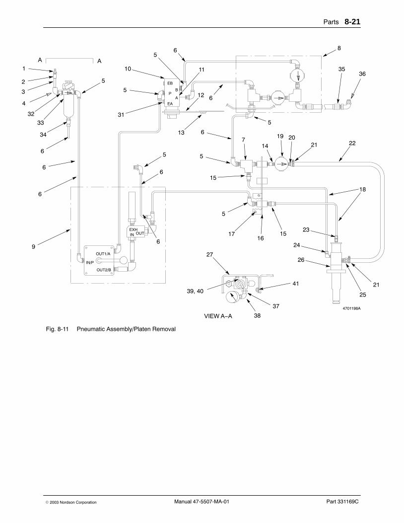
Parts 8-21
Part 331169C� 2003 Nordson Corporation Manual 47-5507-MA-01
4701198A
A A1
32 31
65
10
5
52
3
4
33
34
6
6
6
5
6
6
11
12
13
6
3635
8
22212019
14
6
5
7
5
15
5
1716
15
18
23
24
26
25
21
27
39, 4041
37
38
9
VIEW A−A
OUT1/A
IN/P
OUT2/B
EB
P
EA
B
A
EXHIN OUT
Fig. 8-11 Pneumatic Assembly/Platen Removal
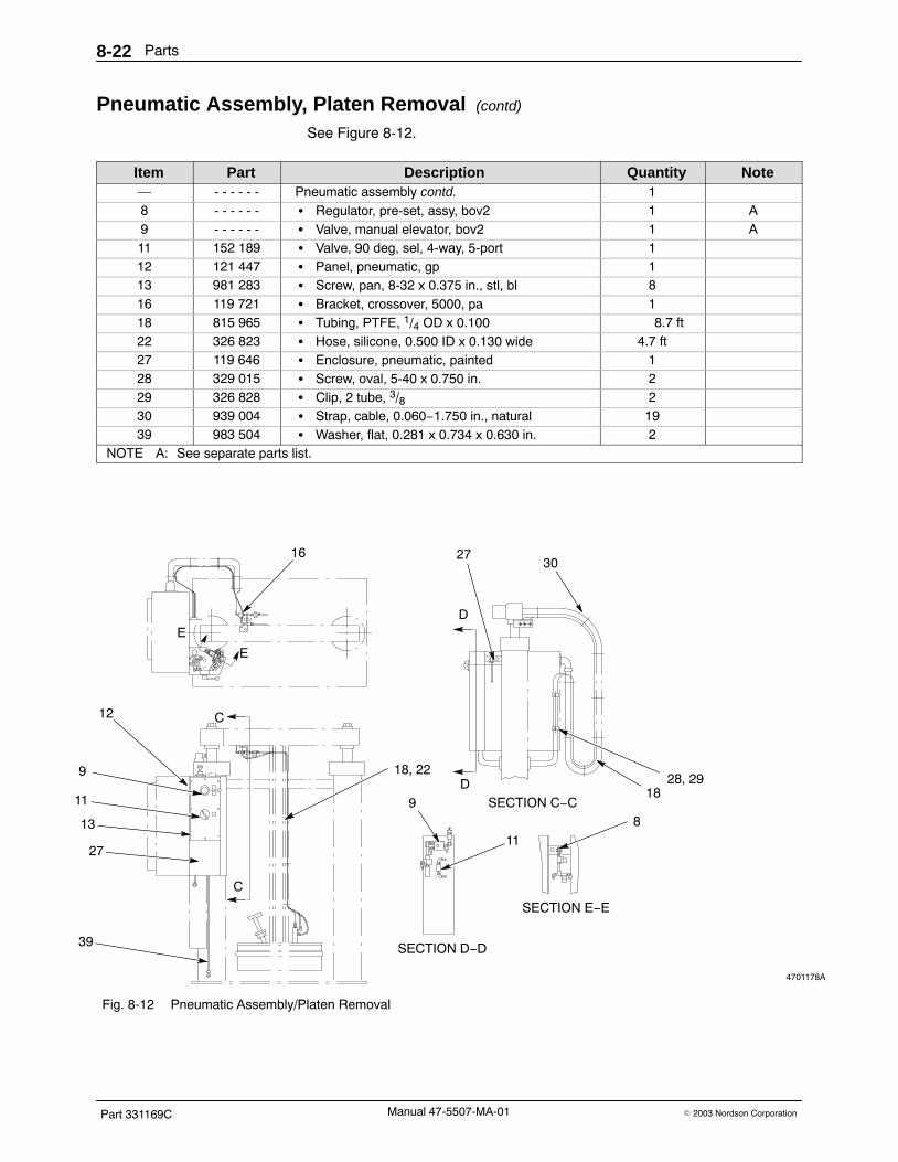
Parts8-22
Part 331169C � 2003 Nordson CorporationManual 47-5507-MA-01
Pneumatic Assembly, Platen Removal (contd)
See Figure 8-12.
Item Part Description Quantity Note— - - - - - - Pneumatic assembly contd. 18 - - - - - - � Regulator, pre-set, assy, bov2 1 A9 - - - - - - � Valve, manual elevator, bov2 1 A11 152 189 � Valve, 90 deg, sel, 4-way, 5-port 112 121 447 � Panel, pneumatic, gp 113 981 283 � Screw, pan, 8-32 x 0.375 in., stl, bl 816 119 721 � Bracket, crossover, 5000, pa 118 815 965 � Tubing, PTFE, 1/4 OD x 0.100 8.7 ft22 326 823 � Hose, silicone, 0.500 ID x 0.130 wide 4.7 ft27 119 646 � Enclosure, pneumatic, painted 128 329 015 � Screw, oval, 5-40 x 0.750 in. 229 326 828 � Clip, 2 tube, 3/8 230 939 004 � Strap, cable, 0.060−1.750 in., natural 1939 983 504 � Washer, flat, 0.281 x 0.734 x 0.630 in. 2
NOTE A: See separate parts list.
4701178A
DSECTION C−C
SECTION D−D
SECTION E−E
16 2730
8
1828, 29
9
11
12
9
11
13
39
27
18, 22
E
E
D
C
C
Fig. 8-12 Pneumatic Assembly/Platen Removal

Parts 8-23
Part 331169C� 2003 Nordson Corporation Manual 47-5507-MA-01
Manual Elevator Valve Assembly See Figure 8-13.
Item Part Description Quantity Note— - - - - - - Valve, manual, elevator, bov2 11 324 208 � Valve, handle, rotary, 1/4 NPT, 4-way 12 972 183 � Elbow, male, 3/8 tube x 1/4 NPT 23 272 556 � Muffler, low-profile, 1/4 NP 14 973 588 � Elbow, pipe, hyd, 45, 1/4 15 973 151 � Ell, pipe, hyd, 90 deg, 1/4 26 973 021 � Nipple, steel, sched 40, 1/4, 3.00 17 326 822 � Valve, quick dump 18 971 655 � Tee, male run, 3/8 tube x 1/4 NPT 19 326 821 � Muffler, 3/8 NPT 1
NS 900 236 � Sealant, paste —NS: Not Shown
4701192A
14
5
6
7
8
9
3
2
5
Fig. 8-13 Manual Elevator Valve Assembly

Parts8-24
Part 331169C � 2003 Nordson CorporationManual 47-5507-MA-01
Regulator Assembly See Figure 8-14.
Item Part Description Quantity Note— - - - - - - Regulator, pre-set, assy, bov2 11 973 275 � Tee, pipe, 1/4, brass 22 973 978 � Adapter, bulkhead, 1/4 NPT 13 330 483 � Valve, check, 1/4, male 14 326 817 � Regulator, pre-set, 10 psi 15 973 021 � Nipple, steel, sched 40, 1/4, 3.00 16 972 183 � Elbow, male, 3/8 tube x 1/4 NPT 27 326 818 � Regulator, pre-set, 30 psi 18 972 200 � Ell, male 37, 9/16-18 x 1/4 1
NS 900 236 � Sealant, paste —NS: Not Shown
4701193A
12
3
5
4
6
7
8
1
Fig. 8-14 Regulator Assembly
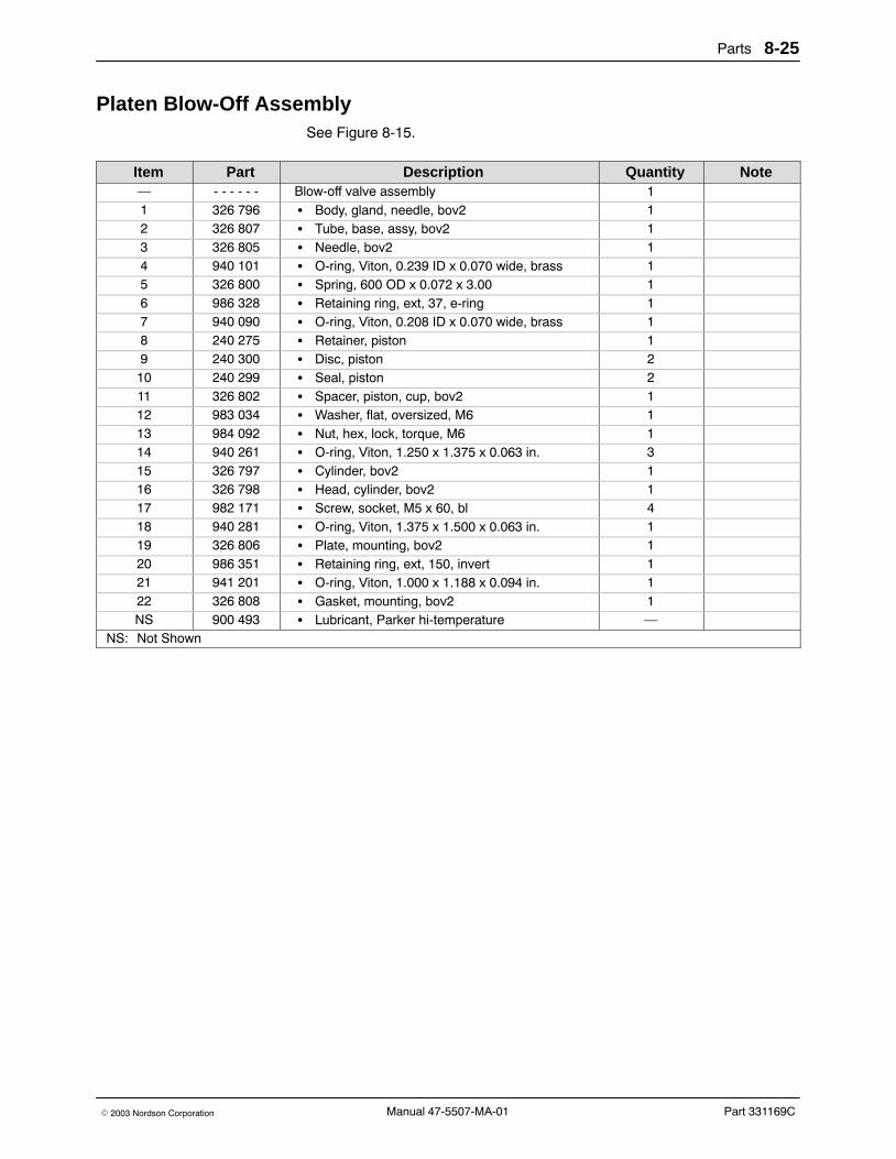
Parts 8-25
Part 331169C� 2003 Nordson Corporation Manual 47-5507-MA-01
Platen Blow-Off Assembly See Figure 8-15.
Item Part Description Quantity Note— - - - - - - Blow-off valve assembly 11 326 796 � Body, gland, needle, bov2 12 326 807 � Tube, base, assy, bov2 13 326 805 � Needle, bov2 14 940 101 � O-ring, Viton, 0.239 ID x 0.070 wide, brass 15 326 800 � Spring, 600 OD x 0.072 x 3.00 16 986 328 � Retaining ring, ext, 37, e-ring 17 940 090 � O-ring, Viton, 0.208 ID x 0.070 wide, brass 18 240 275 � Retainer, piston 19 240 300 � Disc, piston 210 240 299 � Seal, piston 211 326 802 � Spacer, piston, cup, bov2 112 983 034 � Washer, flat, oversized, M6 113 984 092 � Nut, hex, lock, torque, M6 114 940 261 � O-ring, Viton, 1.250 x 1.375 x 0.063 in. 315 326 797 � Cylinder, bov2 116 326 798 � Head, cylinder, bov2 117 982 171 � Screw, socket, M5 x 60, bl 418 940 281 � O-ring, Viton, 1.375 x 1.500 x 0.063 in. 119 326 806 � Plate, mounting, bov2 120 986 351 � Retaining ring, ext, 150, invert 121 941 201 � O-ring, Viton, 1.000 x 1.188 x 0.094 in. 122 326 808 � Gasket, mounting, bov2 1NS 900 493 � Lubricant, Parker hi-temperature —
NS: Not Shown

Parts8-26
Part 331169C � 2003 Nordson CorporationManual 47-5507-MA-01
Platen Blow-Off Assembly (contd)
4701194A
ÇÇÇÇÇÇÇÇÇÇÇÇÇÇÇÇÇÇÉÉÉÉÉÉ
ÉÉÉÉÉÉÉÉÉÉÉÉ
16
9
11
1
14
1918
22
21
3
2
14
20
4
10
1213
15
7
8
17
14
6
10
9
5
Fig. 8-15 Platen Blow-Off Assembly

Parts 8-27
Part 331169C� 2003 Nordson Corporation Manual 47-5507-MA-01
Dual Hose Kit See Figures 8-16 and 8-17.
Item Part Description Quantity Note— - - - - - - Dual hose kit 11 274 307 � Pivot, tube, hose support 12 274 305 � Arm, support, hanger, welded 13 274 174 � Hanger, hose, 5/8 and 1 1/8 in. ID hose units 14 982 006 � Screw, socket, M8 x 20, cap 25 983 404 � Washer, lock, split, M8 26 984 172 � Nut, hex, lock, 1/2-13 17 324 391 � Clip, wire, molded nylon, 0.750 in diameter 18 308 939 � Assembly, pump and manifold, 5/16 in. ID hose 1 A
272 037 � Assembly, pump and manifold, 5/8 in. ID hose 1 A115 785 � Assembly, pump and manifold, 1 1/8 in. ID hose 1 A
9 939 295 � Fuse, 8 amp, time-delay, 250 volt 210 324 315 � Plate, legend, 1 gun 111 939 489 � Potentiometer, 5000 ohms 112 324 314 � Plate, legend, 2 guns 113 325 084 � Wire group 114 933 392 � Base, connector, panel mount 115 933 395 � Insert, connector, receptacle 116 939 528 � Socket, crimp contact, 20-16 gauge 1517 933 396 � Cover, receptacle 118 933 397 � Gasket, base, connector 1NS 900 298 � Compound, heat sink, 5 oz. tube —
NOTE A: Part will vary depending on hose size.
NS: Not Shown

Parts8-28
Part 331169C � 2003 Nordson CorporationManual 47-5507-MA-01
Dual Hose Kit (contd)
4701183A
8
1 2
3
4, 56
BB
VIEW A−A
VIEW B−B7
C
C
A
A
(BEHIND COLUMN)
Fig. 8-16 Dual Hose Kit
4701184A
17
14, 15, 1617, 18
9
10
11, 12
9, 13
SEE DETAIL B
SEE DETAIL A
F
F
VIEW D−D
VIEW C−C
D
D
Fig. 8-17 Dual Hose Kit

Parts 8-29
Part 331169C� 2003 Nordson Corporation Manual 47-5507-MA-01
See Figure 8-18.
Item Part Description Quantity Note— - - - - - - Dual hose kit contd. 111 939 489 � Potentiometer, 5000 ohms 117 933 396 � Cover, receptacle 119 104 049 � Barrier, terminal block 220 104 050 � Jumper, terminal block 321 981 039 � Screw, pan head, 6-32 x 0.312 in. 1022 983 100 � Washer, lock, interior, #6 1023 145 714 � Relay, solid-state, 4 amp, 240 volt 324 939 644 � Triac, tank, control, 25 amp 225 324 912 � Module, temperature, 100�−450� F 226 324 226 � Label, dual hose kit 127 324 403 � Assembly, circuit board, 2-gun controller 128 324 337 � Bracket, support, module 129 981 427 � Screw, pan head, 6-32 x 0.250 230 112 295 � Cover, module, LCU 1
4701185A
20
19
20
19
20
5678
15161718
18
11
29
26
27
21, 22, 24
25
26
2817
21, 22, 23
17
29, 30
DETAIL A DETAIL B
SECTION E−E
SECTION F−F(HEATSINK)
(INSIDE DOOR;LATCH NOT SHOWN)
Fig. 8-18 Dual Hose Kit

Parts8-30
Part 331169C � 2003 Nordson CorporationManual 47-5507-MA-01
Exhaust Hood Assembly See Figure 8-19.
Item Part Description Quantity Note— 331 914 Module, exhaust hood 11 134 916 � Hood, exhaust 12 132 655 � Clip, hood, mounting 33 121 336 � Clamp, hose, worm drive 34 983 410 � Washer, flat, M6 35 983 409 � Washer, lock, split, M6 36 982 135 � Screw, hex, M6 x 30, cap 37 984 703 � Nut, hex, M6 38 222 488 � Handle, T, 55 gal, long 19 945 027 � O-ring, Viton, 1/2 in. tube 110 324 131 � Tray, bleeder valve 111 222 486 � Adapter, T-handle, 55 gal, long 112 986 029 � Retaining ring, ext, 100, spiral 113 900 419 � Adhesive, retaining cylindrical AR
AR: As Required

Parts 8-31
Part 331169C� 2003 Nordson Corporation Manual 47-5507-MA-01
4701195AB
ÉÉÉÉÉÉÉÉÉÉÉÉ
ÉÉÉÉÉÉÉÉÉÉÉÉÉÉÉÉÉÉÉÉÉÉÉÉÉÉÉÉÉÉ
ÇÇÇÇÇÇÇÇÇÇÇÇÇÇÇÇÇÇÇÇÇÇÇÇÇÇÇÇÇÇÇÇÇÇÇÇÇÇÇÇÇÇÇÇÇÇÇÇÇÇÇÇÇÇÇÇÇÇÇÇÇÇÇÇÇÇÇÇÇÇÇÇ
ÉÉÇÇ
ÉÉÉÉÇÇÇÇÇÇÇ
3
2
4, 5, 6, 7 1
8, 9 10, 11, 12, 13
2
2
2
Fig. 8-19 Exhaust Hood Assembly

Parts8-32
Part 331169C � 2003 Nordson CorporationManual 47-5507-MA-01
Hose Parts Lists The following parts lists include hoses for the Model 5507 drummelter/applicator.
Hoses for Manual Guns See Figure 8-20.
Item Part Description Quantity Note— 276 950 Manual Hose, 10 ft, 5/16 in. ID 1— 276 951 Manual Hose, 16 ft, 5/16 in. ID 1— 276 952 Manual Hose, 24 ft, 5/16 in. ID 1— 276 953 Manual Hose, 30 ft, 5/16 in. ID 1— 276 938 Manual Hose, 10 ft, 5/8 in. ID 1— 276 939 Manual Hose, 16 ft, 5/8 in. ID 1— 276 940 Manual Hose, 24 ft, 5/8 in. ID 1— 276 941 Manual Hose, 30 ft, 5/8 in. ID 1— 120 958 Manual Hose, 10 ft, 5/16 in. ID 1 A— 120 959 Manual Hose, 16 ft, 5/16 in. ID 1 A— 127 317 Manual Hose, 10 ft, 5/8 in. ID 1 B— 127 318 Manual Hose, 16 ft, 5/8 in. ID 1 B— 127 319 Manual Hose, 14 ft, 5/8 in. ID 1 B
NOTE A: Equipped with corrugated cover for additional protection from abrasion.
B: For use with Series A-2 handguns only.
4710211
Fig. 8-20 Manual Gun Hose

Parts 8-33
Part 331169C� 2003 Nordson Corporation Manual 47-5507-MA-01
Hoses for Automatic Guns See Figure 8-21.
Item Part Description Quantity Note— 276 946 Automatic Hose, 10 ft, 5/16 in. ID 1— 276 947 Automatic Hose, 16 ft, 5/16 in. ID 1— 276 948 Automatic Hose, 24 ft, 5/16 in. ID 1— 276 949 Automatic Hose, 30 ft, 5/16 in. ID 1— 276 934 Automatic Hose, 10 ft, 5/8 in. ID 1— 276 935 Automatic Hose, 16 ft, 5/8 in. ID 1— 276 936 Automatic Hose, 24 ft, 5/8 in. ID 1— 276 937 Automatic Hose, 30 ft, 5/8 in. ID 1— 100 706 Automatic Hose, 10 ft, 1-1/8 in. ID 1— 100 707 Automatic Hose, 16 ft, 1-1/8 in. ID 1
4710212
Fig. 8-21 Automatic Gun Hose

Parts8-34
Part 331169C � 2003 Nordson CorporationManual 47-5507-MA-01
Transfer Hoses See Figure 8-22.
Item Part Description Quantity Note— 276 942 Transfer Hose, 10 ft, 5/8 in. ID 1 A— 276 943 Transfer Hose, 16 ft, 5/8 in. ID 1 A— 276 944 Transfer Hose, 24 ft, 5/8 in. ID 1 A— 276 945 Transfer Hose, 30 ft, 5/8 in. ID 1 A— 100 704 Transfer Hose, 10 ft, 1-1/8 in. ID 1 A— 100 705 Transfer Hose, 16 ft, 1-1/8 in. ID 1 A
NOTE A: Transfer hoses are used only when there is no gun at the end of the hose
4710216
Fig. 8-22 Transfer Hose

Parts 8-35
Part 331169C� 2003 Nordson Corporation Manual 47-5507-MA-01
Recommended Spare Parts and Kits The following parts lists include spare parts and kits for the Model 5507drum melter/applicator.
Spare Parts and Kits for the Main Assemblies
Part Description Quantity324 207 Filter/Regulator, 1/4 NPTF, 5-150 psig 1324 208 Valve, rotary, hand, 4-way, 1/4 NPT 1942 560 O-ring, buna N (pistons and cylinder heads) 4229 694 Reducer, speed, worm gear, 10:1 1324 725 Motor, electric, 1 hp 1109 362 Brush, motor, 1 hp 2333 719 Pump, replacement, 1000 psi 1333 720 Pump, replacement, 1200 psi 1272 045 Valve, relief, pressure, 1000 psi (1 1/8 in. ID hose) 1272 044 Valve, relief, pressure, 1200 psi (5/8 and 5/16 in. ID hose) 1335 948 Kit, service, uptime 1942 371 � O-ring, Viton, 3 3/8 x 3 5/8 x 1/8 in. 1942 201 � O-ring, Viton, 0.875 x 1.000 x 0.063 in. 1945 025 � O-ring, Viton, 0.750 x 0.950 in. 1940 141 � O-ring, Viton, 0.500 x 0.630 in. 1236 365 � Seal, shaft, 0.625 in. ID x 0.812 in. OD 1236 366 � Seal, shaft, 0.625 in. ID x 0.875 in. OD 2900 318 � Grease, flourinated, 2 oz. tube 1335 946 Kit, service, uptime plus 1335 948 � Kit, service, uptime 1271 917 � Plate, pump, lower 1271 916 � Plate, pump, upper 1236 348 � Bearing, needle, close 1274 300 � Bearing, needle, open 2178 170 � Key, 1/8 square x 0.800 length 1168 054 � Key, woodruff, 1/8 x 1/2 in. 1272 046 � Washer, bearing, 0.520 x 0.875 x 0.062 in. 1986 310 � Ring, retainer, internal 1172 326 � Shaft, pump 1271 888 � Gerotor set, 6-tooth 1172 328 � Block, coupling 1330 601 Thermostat, platen, 93 �C (200 �F) 1330 602 Thermostat, platen, 121 �C (250 �F) 1330 603 Thermostat, platen, 149 �C (300 �F) 1330 604 Thermostat, platen, 177 �C (350 �F) 1288 970 Sensor, temperature, RTD 1271 576 Seal, rubber 1

Parts8-36
Part 331169C � 2003 Nordson CorporationManual 47-5507-MA-01
Spare Parts for the Electrical System
Part Description Quantity Note939 489 Potentiometer, 5000 ohms 1 A237 600 Bulb, pilot 1939 359 Light, pilot, amber 1939 331 Light, pilot, red 1939 644 Triac, 25 amp 1939 763 Relay, solid-state, 660 VAC, 90 amp (200 Volt units) 1939 764 Relay, solid-state, 530 VAC, 40 amp (all other units) 1939 509 Fuse, 5 amp, time-delay, 250 VAC (all units) 1 B, C939 295 Fuse, 8 amp, time-delay, 250 VAC (all units) 1 B, D939 021 Fuse, 20 amp, fast-acting, 600 VAC (all units) 1 B, E939 020 Fuse, 30 amp, fast-acting, 600 VAC (all units) 1 B, F816 243 Fuse, 1.5 amp, time-delay, 500 VAC (380/415V units) 1 B, G939 056 Fuse, 100 amp, time-delay, 250 VAC (200/240V units) 1 B, H939 420 Fuse, 60 amp, time-delay, 600 VAC (380/415V units) 1 B, H939 470 Fuse, 50 amp, time-delay, 600 VAC (480V units) 1 B, H324 403 Board, circuit, 2-gun controller 1324 324 Supply, power, plug-in 1105 051 Kit, service, controller, LCU, 6-channel 1324 912 � Module, temperature, 38−232 �C (100 – 450 �F) 2324 995 � Controller, LCU, 6-channel 1939 823 Transformer, 5 KVA (200/380/415 units) 1939 816 Transformer, 5 KVA (240/480 units) 1
NOTE A: Two provided for dual-hose units.
B: Refer to wiring diagrams, 6-5 or 6-7, for exact location(s) of fuse.
C: F5 at eight-point fuseblock.
D: F10 at eight-point fuseblock and F13 at one-point fuseblock (single-hose units); F11 at eight-pointfuseblock and F14 at two-point fuseblock (dual-hose units).
E: F7 and F9 at eight-point fuseblock.
F: F4 and F6 at eight-point fuseblock.
G: F8 at eight-point fuseblock.
H: F1, F2, and F3 at main disconnect switch
Supplies for Maintenance and Repair
Part Description Quantity324 618 Sealant, joint, TFE —900 223 Lubricant, O-ring, Parker, 4-oz. can 1900 236 Sealant, Paste —900 302 Grease, high-temperature —900 419 Adhesive, retaining, cylindrical —900 464 Adhesive, threadlocking —900 439 Adhesive, threadlocking —900 514 Gloves, protective 1

## TABSHEET ##
SE
CT
ION
9

Supplemental i
Part 331169C� 2003 Nordson Corporation Manual 47-5507-MA-01
Supplemental
Descriptions The following options are available for the model5507 drum melter/applicator.
Parts lists and accompanying illustrations for theClutch Kit and the Run-Up Control Kit follow thesedescriptions.
Instruction Sheets are available for those optionsthat require further installation and/or operationalinstruction.
Clutch Kit The clutch kit is a factory-instaled option that allowsthe motor to remain on while the unit is poweredup, coupling the motor to the speed reducer onlywhen a gun is triggered.
The clutch allows for frequent starting and stoppingof the pump while the motor keeps running,extending the life of the motor.
Automatic Shutdown The automatic shutdown feature is afactory-installed option that turns off the bulkmelter/applicator if the pump is not activated withina specified time period.
This feature is for operating conditions where theunit might be left on unexpectedly for an extendedperiod of time and for use with the 7-day startuptimer option. In these situations, the automaticshutdown option prevents degradation of theadhesive material.
7-Day Digital Startup Timer The 7-day digital startup timer is a factory orcustomer-installed option that includes a solid stateclock with a liquid crystal display (LCD), relay, andmounting hardware.
The clock can be programmed to automaticallystart up the bulk melter/applicator heater channelsover a 7-day period. This feature brings thecomponents of the unit and the adhesive materialto application temperature before productionpersonnel arrive, thereby reducing downtime.
Platen Guard Kit The platen guard kit is a factory orcustomer-installed option that includes a fixed rearpanel, hinged front panel, and mounting hardware.
The platen guard kit increases the safety of theoperator(s) and prevents damage to the platenfrom foreign objects.
Drum Stop The drum stop feature is a customer−installedoption that positions the 55-gallon drum on the bulkmelter/applicator frame base. The drum isautomatically centered under the platen for smoothplaten lowering and quick startup.
Drum Hold-Down The drum hold-down feature is a factory orcustomer-installed option that positions the55-gallon drum on the bulk melter/applicator framebase and secures it for easier platen removal.

Supplementalii
Part 331169C � 2003 Nordson CorporationManual 47-5507-MA-01
Run-Up Control Kit The run-up control kit is a factory-installed optionthat automatically adjusts pump speed as theproduction line speed varies. This featuremaintains a consistent bead thickness.
NOTE: The run-up control kit requires afield-installable run-up sensor/gear kit.
Warning Beacon The warning beacon is a factory orcustomer-installed option that includes apre-assembled lens-and-bulb light tower andmounting hardware.
The amber portion of the warning beacon goes onwhen the low drum level is reached.
The red portion of the warning beacon flashes onand off when the specified empty drum level isreached. The empty drum warning optiondisengages the clutch from the speed reducer orshuts off the motor (units without a clutch).
The warning beacon alerts an operator that a lowand/or empty drum level has been reached.
NOTE: The empty drum option must be installedon your unit for the warning beacon to operateproperly.
Automatic Changeover The automatic changeover feature is afactory-installed option that switches a two-bulkmelter/applicator system from the unit with anempty drum to the unit with a full drum, allowinguninterrupted adhesive application. The optionincludes an enclosure, warning beacon, and controlcircuitry.
Motor Start-Up Timer The motor start-up timer is a factory-installedoption. Based on the user’s setting, the motorstart-up timer provides a time delay of up to twohours in which the motor is disabled. The timedelay allows additional time for hard-to-meltmaterials to become liquid. The SYSTEM READYLED will not light until both conditions have beenmet.

Supplemental iii
Part 331169C� 2003 Nordson Corporation Manual 47-5507-MA-01
Parts Refer to the following tables for parts included inthe Clutch and Run-Up Control options.
Parts lists for other options are included in theaccompanying Instruction Sheet shipped with thatoption.
Clutch Kit Option See Figure 1.
Item Part Description Quantity— - - - - - - Clutch 1
1 933 077 � Conduit 0.7 ft2 933 079 � Connector, conduit 13 324 323 � Clutch, electric 14 983 160 � Washer, lock, split, 0.375 in. 45 981 408 � Screw, hex head, 3/8-16 x 1.250 in. 46 939 122 � Seal, conduit fitting, 1/2 in. 17 933 078 � Connector, straight, 3/8 conduit 18 324 324 � Supply, power, plug-in 1
4701186A
1
6, 7
4, 532
8
JUNCTION BOX DETAIL
Figure 1

Supplementaliv
Part 331169C � 2003 Nordson CorporationManual 47-5507-MA-01
7-Day Timer
Item Part Description Quantity— 129 948 Service kit, 7-day clock
1 981 169 � Screw, pan head, 6-32 x .312, slotted 22 983 102 � Washer, locking split-e, #6 33 983 111 � Washer, locking, split-e, #8 14 981 064 � Screw, pan head, 8-32 x .375 in. 15 939 600 � Relay, time delay, 0.5 second 16 981 577 � Screw, pan head, 6-32 x 1.000 in. 17 111 792 � Timer, programmable, digital 18 336 115 � Label, 7-day clock 19 933 162 � Terminal, Push-on, insulated 250V, 22−18 310 104 704 � Wire, Vinyl, 18 AWG, red 1 ft.
Platen Guard
Item Part Description Quantity— 129 942 Platen Guard
1 271 899 � Handle 12 981 762 � Screw, pan head, 10-32 x 0.875 in., slotted 23 983 120 � Washer, lock, split-e, #10 24 111 714 � Bracket, guard, outside, painted 25 111 712 � Bracket, guard, inside, painted 16 981 208 � Screw, Hex, 1/4-20 x 0.625 in., cap 47 983 051 � Washer, flat, e-ring, 0.344 x 0.688 x 0.065 in. 28 324 958 � Bracket, door, rear 29 981 353 � Screw, hex, 5/16-18 x 1.250 in., cap 210 272 075 � Guard, rear, painted 111 984 140 � Nut, hex, reg, 5/16-18 412 981 521 � Screw, Hex, 5/16-18 x 1.375 in. 213 981 414 � Screw, socket, 3/8-16 x 1.00 in. 414 981 759 � Screw, panhead, 4-40 x 0.312 in., slotted 615 983 526 � Lockwasher, split-e, #4 616 271 905 � Magnet, door 317 271 906 � Bracket, Mounting, magnet 318 983 140 � Washer, lock, split-e, 1/4 in. 419 983 040 � Washer, flat, e-ring, 0.266 x 0.625 x 0.049 in. 4
Drum Stop
Item Part Description Quantity— 133 285 Drum stop 11 133 293 � Bracket assembly, drum stop 22 981 273 � Screw, hex, 1/4-20 x 1.500 in. 23 984 210 � Nut, hex, jam, 1/4-20 24 983 061 � Washer, flat, e-ring, 0.406 x 0.812 x 0.065 in. 45 603 348 � Label, blank, 3.000 in. x 5.000 in. 1

Supplemental v
Part 331169C� 2003 Nordson Corporation Manual 47-5507-MA-01
Item Part Description Quantity— 133 290 Clamp, stop, drum 11 133 285 � Option package, drum stop 12 981 273 � � Screw, hex head, 1/4-20 x 1.5 in. 23 984 210 � � Nut, Hex, jam, 1/4-20 24 981 403 � � Screw, hex, 3/8-16 x 2.750 in., cap 45 983 061 � � Washer, flat, e-ring, 0.406 x 0.812 x 0.065 in. 46 603 348 � � Label, blank, e.00 in. x 5.00 in. 17 133 283 � Option package, drum clamp 18 133 294 � � Arm assembly, drum clamp 19 983 007 � � � Washer, flat, e-ring, 0.531 x 1.000 x 0.063 in. 310 983 180 � � � Washer, locking, split-e, 1/2 in. 211 984 171 � � � Nut, hex, jam, 1/2-20 212 126 207 � � � Arm, drum clamp, 5000 113 986 314 � � � Retaining ring, ext, 100 basic 114 984 170 � � � Nut, hex, regular, 1/2-13 115 133 298 � � Lever assembly, drum stop 116 126 163 � � � Lever, drum clamp 117 986 315 � � � Retaining ring, ext, 50, basic 218 126 183 � � Retainer, clamp, drum, 5000 119 981 833 � � Screw, flat, socket, 5/16-18 x 0.750 in. 1220 981 611 � � Screw, hex, 1/2-13 x 1.0 in., cap 121 984 170 � � Nut, hex, reg, 1/2-13 122 983 180 � � Washer, lock, split-e, 1/2 in. 123 981 350 � � Screw, hex, 5/16-18 x 2.750, cap 424 983 150 � � Washer, lock, split-e, 5/16 in. 425 603 348 � � Label, blank, 3.00 in. x 5.00 in. 1
Drum Stop Clamp

Supplementalvi
Part 331169C � 2003 Nordson CorporationManual 47-5507-MA-01
Run-Up Control Kit Option See Figure 2.
Item Part Description Quantity— - - - - - - Run-up control 11 324 450 � Board, isolation (for A2000) 12 324 451 � Converter, analog gear to line 13 324 452 � Socket, converter, gear to line 14 324 453 � Mount, switch 15 - - - - - - � Label, switch, run-up 16 - - - - - - � Module, run-up, sensor/gear 17 937 188 � Switch w/ plastic handle, toggle 18 981 039 � Screw, pan head, 6-32 x 0.312 in. 29 981 072 � Screw, pan head, 8-32 x 1.000 in. 210 983 102 � Washer, lock, split, #6 211 324 458 � Connector, relief, strain 112 939 475 � Locknut, conduit, 1/2 113 983 010 � Washer, flat, 0.188 x 0.375 x 0.040 in. 214 939 122 � Seal, conduit fitting, 1/2 115 983 111 � Washer, lock, split, #8 2
4701187
OFF
ON
6
1
4, 8, 10
7
2
11, 12, 14 39, 13, 15
5
Figure 2 Run-Up Control

Supplemental vii
Part 331169C� 2003 Nordson Corporation Manual 47-5507-MA-01
Indicator Light Tower
Item Part Description Quantity— 129 941 Service kit, indicator light 11 336 096 � Light, cover & base for alarm indicator 12 336 090 � Light, alarm lens, orange, stack 13 336 091 � Light tube, 4: alarm indicator, stack 14 336 089 � Light, alarm lens, red, stack 15 336 097 � Lamp, 120V, alarm indicator, stack 26 336 095 � Light mounting tulip, alarm indicator, stack 17 336 098 � Gasket, light alarm, tulip mounting 18 100 460 � Wire group, light indicator 19 931 170 � � Wire, vinyl, 18 AWG, red 15 ft.10 931 225 � � Wire, 250C, 14 AWG, green w/yellow 4 ft.11 981 054 � Screw. pan head. 9-32 x 0.750 in. 412 984 111 � Nut, hex, machine, #8-32 413 983 111 � Washer, lock, split-e, #8 414 983 010 � Washer, flat, e-ring, 0.188 x 0.375 x 0.040 in. 4

Supplementalviii
Part 331169C � 2003 Nordson CorporationManual 47-5507-MA-01