series 84 attractive. versatile and functional. · information about the series key advantages §...
TRANSCRIPT

Series
Series 84 Attractive. Versatile and functional.
84
https://eao.com/84

Information about the SeriesKey advantages
§Attractive design and reliable operation §IP67 front protection §Powerful, consistent illumination with innovative technologies§Animated illumination options for a wide variety of potential ap-
plications §Available with soldered, plug, PCB and flat ribbon cable termi-
nals
Typical application areas
§Machinery§Measurement and control engineering§Lifting and handling equipment§Process automation§Special vehicles§Ticketing machines§Medical equipment
Functions
§Pushbutton§Illuminated pushbutton§Indicator
Design
§Flush§Raised
IP front protection
§IP40§IP65§IP67
Raitings
§42 VAC (100 mA)§240 VAC (1.5 A)
Mounting cut-outs
§Ø 22.3 mm§Ø 30.5 mm
Terminal
§Soldering/plug-in terminal§PCB§Cable
Lens Material
§Aluminium§Plastic
Markings
§Engraving§Laser marking§Hot stamping§Pad printing§Screen print§Milling
Approvals
§CB (IEC 60947)§UL§TSI PRM
Conformities
§CE§2006/42/EC (MD)§2011/65/EC (RoHS)§1300/2014 (PRM)§2014/30/EU (EMC)
84
eao.com § 12/2019 2

Flush design
Pushbutton standard
Pushbutton PCB standard
Pushbutton ring illumination standard
Pushbutton ring illumination PCB standard
Pushbutton ring illumination PCB or Halo compact
Illuminated pushbutton standard
Illuminated pushbutton PCB standard
Indicator standard
Indicator PCB standard
Indicator ring illumination standard
Indicator ring illumination PCB standard
Indicator ring illumination PCB or Halo compact
Raised design
Stop switch
Emergency stop switch
Emergency stop switch, Bi-Colour
Components
Accessories
Technical data
Application guidelines
Index
Content
4
6
8
9
10
11
13
15
16
17
18
19
20
23
26
28
43
52
57
58
12/2019 § eao.com 3
8401
02
03
04
09
14
17
18
19
22
31
41
45
51
56
57
61
70
71
82
84
92
96

Pushbutton standard, IP40, IP67
Equipment consisting of (schematic overview)
Lens Page 28
Actuator
Fixing nut
Switching element Page 33
Each Part Number listed below includes all the black components shown in the 3D-drawing.
To obtain a complete unit, please select the red components from the pages shown.
Dimensions [mm] A = Plug-in terminal 2.8 mm x 0.5 mmB = Flat ribbon cableD = Lens level with bezelE = Lens raised above bezelF = Lens konvexe level with bezelG =Lens convexe raised above bezelH = Mushroom-head cap
Product can differ from the current configuration.
Mounting cut-outs [mm]
General information
• Non-illuminated lens and bezel
• The colour of anodised aluminium parts can vary due to technical production reasons
Actuator
Switching action Front bezel colour Front bezel material IP front protection Dimensions Part No. Wiring diagram
Momentary Black Plastic IP67 Ø 25 mm 84-1101.0 72
Black Aluminium IP67 Ø 25 mm 84-1201.0 72
Red Aluminium IP67 Ø 25 mm 84-1201.2 72
Gold Aluminium IP67 Ø 25 mm 84-1201.4 72
Olive Aluminium IP67 Ø 25 mm 84-1201.5 72
Blue Aluminium IP67 Ø 25 mm 84-1201.6 72
Nature Aluminium IP67 Ø 25 mm 84-1201.7 72
Black Plastic IP40 Ø 25 mm 84-2101.0 294
Flush design
eao.com § 12/2019 4
84
Ø25
Ø40
5 7
6 max.
2
4
4
23
9
23 300 ±10
9.5
Ø32
3 max.
21
9
21 300 ±10
A B
A B
E H
D
D
E
F
G
H
GFD
01
02
03
04
09
14
17
18
19
22
31
41
45
51
56
57
61
70
71
82
84
92
96

Actuator
Switching action Front bezel colour Front bezel material IP front protection Dimensions Part No. Wiring diagram
Momentary Nature Aluminium IP67 Ø 40 mm 84-1221.7 294
Wiring diagrams
Wiring diagram 72 Wiring diagram 294
Flush design
12/2019 § eao.com 5
84
x2+
x1-
01
02
03
04
09
14
17
18
19
22
31
41
45
51
56
57
61
70
71
82
84
92
96

Pushbutton PCB standard, IP40, IP67
Equipment consisting of (schematic overview)
Lens Page 28
Actuator
Fixing nut
Mounting flange Page 42
Switching element Page 33
Each Part Number listed below includes all the black components shown in the 3D-drawing.
To obtain a complete unit, please select the red components from the pages shown.
Dimensions [mm] D = Lens level with bezelE = Lens raised above bezelF = Lens konvexe level with bezelG = Lens convexe raised above bezelH = Mushroom-head cap
Product can differ from the current configuration.
Mounting cut-outs [mm]
General information
• Non-illuminated lens and bezel
• The colour of anodised aluminium parts can vary due to technical production reasons
Actuator
Switching action Front bezel colour Front bezel material IP front protection Dimensions Part No. Wiring diagram
Momentary Black Plastic IP67 Ø 25 mm 84-1101.0 72
Black Aluminium IP67 Ø 25 mm 84-1201.0 72
Red Aluminium IP67 Ø 25 mm 84-1201.2 72
Gold Aluminium IP67 Ø 25 mm 84-1201.4 72
Olive Aluminium IP67 Ø 25 mm 84-1201.5 72
Blue Aluminium IP67 Ø 25 mm 84-1201.6 72
Nature Aluminium IP67 Ø 25 mm 84-1201.7 72
Black Plastic IP40 Ø 25 mm 84-2101.0 294
Actuator
Switching action Front bezel colour Front bezel material IP front protection Dimensions Part No. Wiring diagram
Momentary Nature Aluminium IP67 Ø 40 mm 84-1221.7 294
Flush design
eao.com § 12/2019 6
84
Ø25
5 74 9.5
Ø32
4max.
3.6182
Ø40
3max.
3.6164
E HGFD
E HGFD D
01
02
03
04
09
14
17
18
19
22
31
41
45
51
56
57
61
70
71
82
84
92
96

Wiring diagrams
Wiring diagram 72 Wiring diagram 294
Flush design
www.eao.com/84-e-stop
Compact, attractive and reliable. Series 84 E-Stop switches.
Ideal for challenging applications – thanks to the attractive design and the very low back panel depth.
. Robust mono-block
. Foolproof and fail-safe design
. Very low back panel depth
. Attractive, modern design and protection IP65 / 67
. Reliable and long service life
. Clearly visible illumination
12/2019 § eao.com 7
84
x2+
x1-
01
02
03
04
09
14
17
18
19
22
31
41
45
51
56
57
61
70
71
82
84
92
96
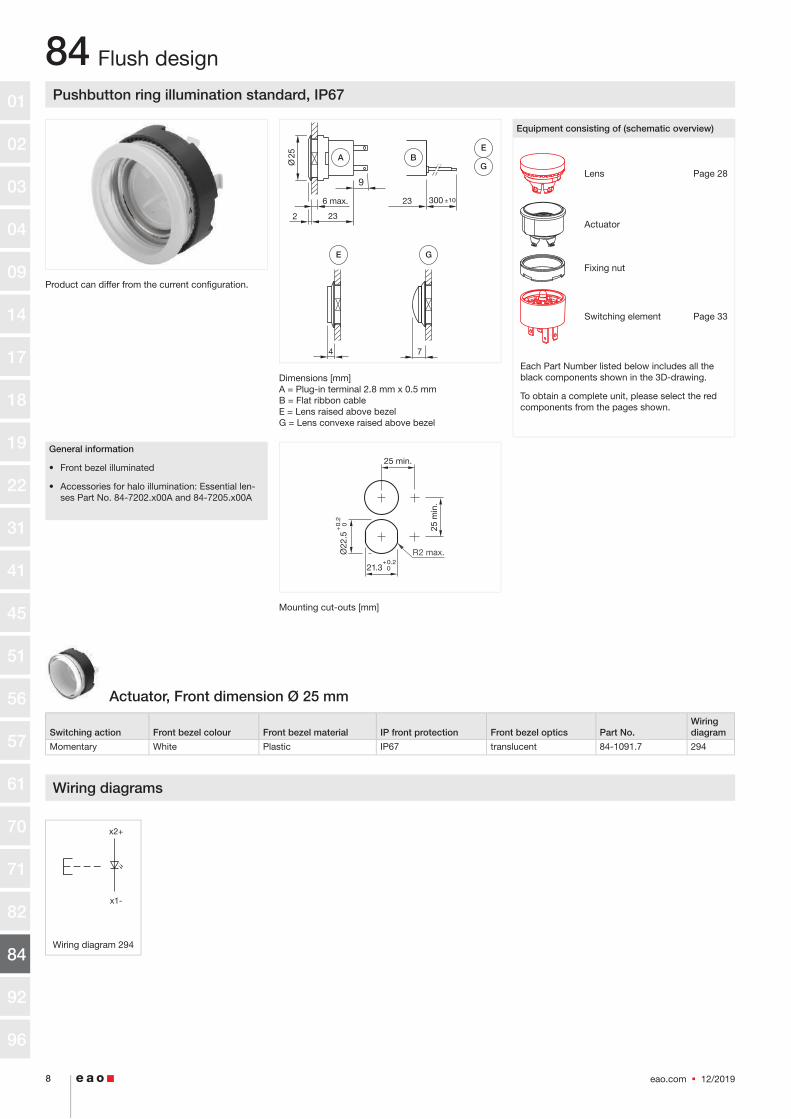
Pushbutton ring illumination standard, IP67
Equipment consisting of (schematic overview)
Lens Page 28
Actuator
Fixing nut
Switching element Page 33
Each Part Number listed below includes all the black components shown in the 3D-drawing.
To obtain a complete unit, please select the red components from the pages shown.
Dimensions [mm] A = Plug-in terminal 2.8 mm x 0.5 mmB = Flat ribbon cableE = Lens raised above bezelG = Lens convexe raised above bezel
Product can differ from the current configuration.
Mounting cut-outs [mm]
General information
• Front bezel illuminated
• Accessories for halo illumination: Essential len-ses Part No. 84-7202.x00A and 84-7205.x00A
Actuator, Front dimension Ø 25 mm
Switching action Front bezel colour Front bezel material IP front protection Front bezel optics Part No. Wiring diagram
Momentary White Plastic IP67 translucent 84-1091.7 294
Wiring diagrams
Wiring diagram 294
Flush design
eao.com § 12/2019 8
84
Ø25
7
6 max.
2
4
23
9
23 300 ±10
A BE
E G
G
x2+
x1-
01
02
03
04
09
14
17
18
19
22
31
41
45
51
56
57
61
70
71
82
84
92
96

Pushbutton ring illumination PCB standard, IP67
Equipment consisting of (schematic overview)
Lens Page 28
Actuator
Fixing nut
Mounting flange Page 42
Single-LED Page 32
Switching element Page 33
Each Part Number listed below includes all the black components shown in the 3D-drawing.
To obtain a complete unit, please select the red components from the pages shown.
Dimensions [mm] E = Lens raised above bezelG = Lens convexe raised above bezel
Product can differ from the current configuration.
Mounting cut-outs [mm]
General information
• Front bezel illuminated
• Accessories for halo illumination: Essential len-ses Part No. 84-7202.x00A and 84-7205.x00A
Actuator, Front dimension Ø 25 mm
Switching action Front bezel colour Front bezel material IP front protection Front bezel optics Part No. Wiring diagram
Momentary White Plastic IP67 translucent 84-1091.7 294
Wiring diagrams
Wiring diagram 294
Flush design
12/2019 § eao.com 9
84
74
Ø25
4max.
3.6182
G GEE
x2+
x1-
01
02
03
04
09
14
17
18
19
22
31
41
45
51
56
57
61
70
71
82
84
92
96

Pushbutton ring illumination PCB or Halo compact, IP67
Equipment consisting of (schematic overview)
Lens Page 28
Actuator
Fixing nut
Mounting flange Page 42
Single-LED Page 32
Switching element Page 33
Each Part Number listed below includes all the black components shown in the 3D-drawing.
To obtain a complete unit, please select the red components from the pages shown.
Dimensions [mm] D = Lens level with bezelE = Lens raised above bezelF = Lens konvexe level with bezelG = Lens convexe raised above bezel
Product can differ from the current configuration.
Mounting cut-outs [mm]
General information
• The mini TOP LEDs are not part of delivery. Re-commendation: Osram Hyper Mini TOP LED
Actuator, Front dimension Ø 25 mm
Switching action Front bezel colour Front bezel material IP front protection Front bezel optics Part No. Wiring diagram
Momentary Colourless Plastic IP67 transparent 84-1081.7 294
Wiring diagrams
Wiring diagram 294
Flush design
eao.com § 12/2019 10
84
5 74
Ø25
4max.
3.6182
E GFD
E GFD
x2+
x1-
01
02
03
04
09
14
17
18
19
22
31
41
45
51
56
57
61
70
71
82
84
92
96

Illuminated pushbutton standard, IP40, IP67
Equipment consisting of (schematic overview)
Lens Page 28
Actuator
Fixing nut
Switching element Page 33
Each Part Number listed below includes all the black components shown in the 3D-drawing.
To obtain a complete unit, please select the red components from the pages shown.
Dimensions [mm] A = Plug-in terminal 2.8 mm x 0.5 mmB = Flat ribbon cableD = Lens level with bezelE = Lens raised above bezelH = Mushroom-head cap
Product can differ from the current configuration.
Mounting cut-outs [mm]
General information
• Illuminated lens, non-illuminated bezel
• The colour of anodised aluminium parts can vary due to technical production reasons
Actuator
Switching action Front bezel colour Front bezel material IP front protection Dimensions Part No. Wiring diagram
Momentary Black Plastic IP67 Ø 25 mm 84-1101.0 72
Black Aluminium IP67 Ø 25 mm 84-1201.0 72
Red Aluminium IP67 Ø 25 mm 84-1201.2 72
Gold Aluminium IP67 Ø 25 mm 84-1201.4 72
Olive Aluminium IP67 Ø 25 mm 84-1201.5 72
Blue Aluminium IP67 Ø 25 mm 84-1201.6 72
Nature Aluminium IP67 Ø 25 mm 84-1201.7 72
Black Plastic IP40 Ø 25 mm 84-2101.0 294
Flush design
12/2019 § eao.com 11
84
Ø25
Ø40
6 max.
2
4
4
23
9
23 300 ±10
3 max.
21
9
21 300 ±10
9.5
Ø32
AD
D
D E H
E
H
B
A B
01
02
03
04
09
14
17
18
19
22
31
41
45
51
56
57
61
70
71
82
84
92
96

Actuator
Switching action Front bezel colour Front bezel material IP front protection Dimensions Part No. Wiring diagram
Momentary Nature Aluminium IP67 Ø 40 mm 84-1221.7 294
Wiring diagrams
Wiring diagram 72 Wiring diagram 294
Flush design
www.eao.com
On our website you can download technical data, assembly instructions, catalogs, brochures and much more.
EAO Downloads.www.eao.com/downloadsEAO creates possibilities. Since 1947.
eao.com § 12/2019 12
84
x2+
x1-
01
02
03
04
09
14
17
18
19
22
31
41
45
51
56
57
61
70
71
82
84
92
96

Illuminated pushbutton PCB standard, IP40, IP67
Equipment consisting of (schematic overview)
Lens Page 28
Actuator
Fixing nut
Mounting flange Page 42
Single-LED Page 32
Switching element Page 33
Each Part Number listed below includes all the black components shown in the 3D-drawing.
To obtain a complete unit, please select the red components from the pages shown.
Dimensions [mm] A = Lens level with bezelE = Lens raised above bezelH = Mushroom-head cap
Product can differ from the current configuration.
Mounting cut-outs [mm]
General information
• Illuminated lens, non-illuminated bezel
• The colour of anodised aluminium parts can vary due to technical production reasons
Actuator
Switching action Front bezel colour Front bezel material IP front protection Dimensions Part No. Wiring diagram
Momentary Black Plastic IP67 Ø 25 mm 84-1101.0 72
Black Aluminium IP67 Ø 25 mm 84-1201.0 72
Red Aluminium IP67 Ø 25 mm 84-1201.2 72
Gold Aluminium IP67 Ø 25 mm 84-1201.4 72
Olive Aluminium IP67 Ø 25 mm 84-1201.5 72
Blue Aluminium IP67 Ø 25 mm 84-1201.6 72
Nature Aluminium IP67 Ø 25 mm 84-1201.7 72
Black Plastic IP40 Ø 25 mm 84-2101.0 294
Actuator
Switching action Front bezel colour Front bezel material IP front protection Dimensions Part No. Wiring diagram
Momentary Nature Aluminium IP67 Ø 40 mm 84-1221.7 294
Flush design
12/2019 § eao.com 13
84
4 9.5
Ø32
Ø25
4max.
3.6182
Ø40
3max.
3.6164
E HD
E HD
D
01
02
03
04
09
14
17
18
19
22
31
41
45
51
56
57
61
70
71
82
84
92
96

Wiring diagrams
Wiring diagram 72 Wiring diagram 294
Flush design
eao.com § 12/2019 14
84
x2+
x1-
01
02
03
04
09
14
17
18
19
22
31
41
45
51
56
57
61
70
71
82
84
92
96

Indicator standard, IP40, IP67
Equipment consisting of (schematic overview)
Lens Page 28
Actuator
Fixing nut
Illumination element Page 37
Each Part Number listed below includes all the black components shown in the 3D-drawing.
To obtain a complete unit, please select the red components from the pages shown.
Dimensions [mm] A = Plug-in terminal 2.8 mm x 0.5 mmB = Flat ribbon cableD = Lens level with bezelE = Lens raised above bezelH = Mushroom-head cap
Product can differ from the current configuration.
Mounting cut-outs [mm]
General information
• Illuminated lens, non-illuminated bezel
• The colour of anodised aluminium parts can vary due to technical production reasons
Actuator, Front dimension Ø 25 mm
IP front protection Front bezel colour Front bezel material Part No. Wiring diagram
IP67 Black Plastic 84-0100.0 70
Nature Aluminium 84-0200.7 70
IP40 Black Plastic 84-3100.0 70
Wiring diagrams
Wiring diagram 70
Flush design
12/2019 § eao.com 15
84
Ø25
6 max.
2
4
23
9
23 300 ±10
9.5
Ø32
A B
D
D E H
E
H
x2+
x1-
01
02
03
04
09
14
17
18
19
22
31
41
45
51
56
57
61
70
71
82
84
92
96

Indicator PCB standard, IP40, IP67
Equipment consisting of (schematic overview)
Lens Page 28
Actuator
Fixing nut
Mounting flange Page 42
Single-LED Page 32
Illumination element Page 37
Each Part Number listed below includes all the black components shown in the 3D-drawing.
To obtain a complete unit, please select the red components from the pages shown.
Dimensions [mm] A = Lens level with bezelE = Lens raised above bezelH = Mushroom-head cap
Product can differ from the current configuration.
Mounting cut-outs [mm]
General information
• Illuminated lens, non-illuminated bezel
• The colour of anodised aluminium parts can vary due to technical production reasons
Actuator, Front dimension Ø 25 mm
IP front protection Front bezel colour Front bezel material Part No. Wiring diagram
IP67 Black Plastic 84-0100.0 70
Nature Aluminium 84-0200.7 70
IP40 Black Plastic 84-3100.0 70
Wiring diagrams
Wiring diagram 70
Flush design
eao.com § 12/2019 16
84
4
Ø25
4max.
3.6182
9.5
Ø32
D E H
x2+
x1-
01
02
03
04
09
14
17
18
19
22
31
41
45
51
56
57
61
70
71
82
84
92
96

Indicator ring illumination standard, IP67
Equipment consisting of (schematic overview)
Lens Page 28
Actuator
Fixing nut
Illumination element Page 37
Each Part Number listed below includes all the black components shown in the 3D-drawing.
To obtain a complete unit, please select the red components from the pages shown.
Dimensions [mm] A = Plug-in terminal 2.8 mm x 0.5 mmB = Flat ribbon cableE = Lens raised above bezelG = Lens convexe raised above bezel
Product can differ from the current configuration.
Mounting cut-outs [mm]
General information
• Front bezel illuminated
• Accessories for halo illumination: Essential len-ses Part No. 84-7202.x00A and 84-7205.x00A
Actuator, Front dimension Ø 25 mm
IP front protection Front bezel colour Front bezel material Front bezel optics Part No. Wiring diagram
IP67 Colourless Plastic translucent 84-0090.7 70
Wiring diagrams
Wiring diagram 70
Flush design
12/2019 § eao.com 17
84
Ø25
7
6 max.
2
4
23
9
23 300 ±10
A BE
E G
G
x2+
x1-
01
02
03
04
09
14
17
18
19
22
31
41
45
51
56
57
61
70
71
82
84
92
96

Indicator ring illumination PCB standard, IP67
Equipment consisting of (schematic overview)
Lens Page 28
Actuator
Fixing nut
Mounting flange Page 42
Single-LED Page 32
Illumination element Page 37
Each Part Number listed below includes all the black components shown in the 3D-drawing.
To obtain a complete unit, please select the red components from the pages shown.
Dimensions [mm] E = Lens raised above bezelG = Lens convexe raised above bezel
Product can differ from the current configuration.
Mounting cut-outs [mm]
General information
• Front bezel illuminated
• Accessories for halo illumination: Essential len-ses Part No. 84-7202.x00A and 84-7205.x00A
Actuator, Front dimension Ø 25 mm
IP front protection Front bezel colour Front bezel material Front bezel optics Part No. Wiring diagram
IP67 Colourless Plastic translucent 84-0090.7 70
Wiring diagrams
Wiring diagram 70
Flush design
eao.com § 12/2019 18
84
74
Ø25
4max.
3.6182
G GEE
x2+
x1-
01
02
03
04
09
14
17
18
19
22
31
41
45
51
56
57
61
70
71
82
84
92
96

Indicator ring illumination PCB or Halo compact, IP67
Equipment consisting of (schematic overview)
Lens Page 28
Actuator
Fixing nut
Mounting flange Page 42
Single-LED Page 32
Illumination element Page 37
Each Part Number listed below includes all the black components shown in the 3D-drawing.
To obtain a complete unit, please select the red components from the pages shown.
Dimensions [mm] D = Lens level with bezelE = Lens raised above bezelF = Lens konvexe level with bezelG = Lens convexe raised above bezel
Product can differ from the current configuration.
Mounting cut-outs [mm]
General information
• The mini TOP LEDs are not part of delivery. Re-commendation: Osram Hyper Mini TOP LED
Actuator, Front dimension Ø 25 mm
IP front protection Front bezel colour Front bezel material Front bezel optics Part No. Wiring diagram
IP67 Colourless Plastic transparent 84-0080.7 70
Wiring diagrams
Wiring diagram 70
Flush design
12/2019 § eao.com 19
84
5 74
Ø25
4max.
3.6182
E GFD
E GFD
x2+
x1-
01
02
03
04
09
14
17
18
19
22
31
41
45
51
56
57
61
70
71
82
84
92
96

Stop switch, IP65, IP66, IP67
Equipment consisting of (schematic overview)
Actuator
Fixing nut
Each Part Number listed below includes all the black components shown in the 3D-drawing.
Dimensions [mm] A = Plug-in terminal 2.8 mm x 0.5 mmB = Flat ribbon cable
Product can differ from the current configuration.
Mounting cut-outs [mm]
General information
• Position indication ring black
• Lens plastic grey
Stop switch, Front dimension Ø 32 mm
Switching action Contacts Terminal Illumination colour Part No. Wiring diagram
Compo-nent Layout
Maintained 1 NC Flat ribbon cable 84-6220.0040 426 98
1 NC / 1 NO Flat ribbon cable 84-6830.0040 427 98
2 NC Flat ribbon cable 84-6840.0040 428 98
1 NC Flat ribbon cable Red 84-6821.2B40 429 98
1 NC / 1 NO Flat ribbon cable Red 84-6831.2B40 431 98
2 NC Flat ribbon cable Red 84-6841.2B40 430 98
1 NC Plug-in terminal 84-6220.0020 345 99
1 NC / 1 NO Plug-in terminal 84-6830.0020 346 99
2 NC Plug-in terminal 84-6840.0020 347 99
1 NC Plug-in terminal Red 84-6821.2B20 348 99
1 NC / 1 NO Plug-in terminal Red 84-6831.2B20 349 99
2 NC Plug-in terminal Red 84-6841.2B20 350 99
Contacts: NC = Normally closed, NO = Normally open
Raised design
eao.com § 12/2019 20
84
26
18
9.5
13.5
1...4
300
Ø32
±10
A
B
01
02
03
04
09
14
17
18
19
22
31
41
45
51
56
57
61
70
71
82
84
92
96

Wiring diagrams
Wiring diagram 345 Wiring diagram 346 Wiring diagram 347 Wiring diagram 348 Wiring diagram 349
Wiring diagram 350 Wiring diagram 426 Wiring diagram 427 Wiring diagram 428
Wiring diagram 429 Wiring diagram 430
Component layouts
Component layout 98
Dimensions [mm]A = CableB = whiteC = brownD = greenE = yellowF = greyG = pinkH = TerminalsI = Illumination
Raised design
12/2019 § eao.com 21
84
11
12
23
24
11
12
21
22
11
12
11
12 X1–
X2+ 23
24
11
12 X1–
X2+
21
22
11
12 X1–
X2+ br (11)
wt (12)
gr (23)
rd (24)
br (11)
wt (12)
gr (21)
rd (22)
br (11)
wt (12)
br (11)
wt (12) gn (X1–)
ye (X2+) gr (23)
rd (24)
br (11)
wt (12) gn (X1–)
ye (X2+)
X2+
X1-
12
1123
24
21 2
2
1112
X1_
X2+24 2223 21
1112
1112
24 2223 21
1 Ö + 1 S2 Ö
11 / 12 + 23 / 2411 / 12 + 21 / 22X1_ / X2+
1112
X1_
X2+
1 Ö 11 / 12X1_ / X2+
1 Ö + 1 S2 Ö
11 / 12 + 23 / 2411 / 12 + 21 / 22
1 Ö 11 / 12
D
B
A
C
G
E
D
BC
E
D
BC
E
H
H
I
I
H
H
F
01
02
03
04
09
14
17
18
19
22
31
41
45
51
56
57
61
70
71
82
84
92
96

Component layouts
Component layout 99
Raised design
www.eao.com/84-e-stop
Compact, attractive and reliable. Series 84 E-Stop switches.
Ideal for challenging applications – thanks to the attractive design and the very low back panel depth.
. Robust mono-block
. Foolproof and fail-safe design
. Very low back panel depth
. Attractive, modern design and protection IP65 / 67
. Reliable and long service life
. Clearly visible illumination
eao.com § 12/2019 22
84
12 11
X2+ X1-
24 2322 21
01
02
03
04
09
14
17
18
19
22
31
41
45
51
56
57
61
70
71
82
84
92
96

Emergency stop switch, IP65, IP66, IP67
Equipment consisting of (schematic overview)
Actuator
Fixing nut
Each Part Number listed below includes all the black components shown in the 3D-drawing.
Dimensions [mm] A = Plug-in terminal 2.8 mm x 0.5 mmB = Flat ribbon cable
Product can differ from the current configuration.
Mounting cut-outs [mm]
General information
• Lens plastic red
Emergency stop switch, Front dimension Ø 32 mm
Switching action Contacts Terminal Illumination colour Product attributes Part No. Wiring diagram
Compo-nent Layout
Maintained 1 NC Plug-in terminal Switching position ring black 84-5220.0020 345 99
1 NC Flat ribbon cable Switching position ring black 84-5220.0040 426 98
1 NC Plug-in terminal Red Switching position ring black 84-5221.2B20 348 99
1 NC Flat ribbon cable Red Switching position ring black 84-5221.2B40 429 98
1 NC / 1 NO Plug-in terminal Switching position ring black 84-5230.0020 346 99
1 NC / 1 NO Flat ribbon cable Switching position ring black 84-5230.0040 427 98
1 NC / 1 NO Plug-in terminal Red Switching position ring black 84-5231.2B20 349 99
1 NC / 1 NO Flat ribbon cable Red Switching position ring black 84-5231.2B40 430 98
2 NC Plug-in terminal Switching position ring black 84-5240.0020 347 99
2 NC Flat ribbon cable Switching position ring black 84-5240.0040 428 98
2 NC Plug-in terminal Red Switching position ring black 84-5241.2B20 350 99
2 NC Flat ribbon cable Red Switching position ring black 84-5241.2B40 431 98
1 NC Plug-in terminal Switching position ring green 84-5320.0020 345 99
Contacts: NC = Normally closed, NO = Normally open
Raised design
12/2019 § eao.com 23
84
26
18
9.5
13.5
1...4
300
Ø32
±10
A
B
01
02
03
04
09
14
17
18
19
22
31
41
45
51
56
57
61
70
71
82
84
92
96

Switching ac-tion Contacts Terminal
Illumination co-lour Product attributes Part No.
Wiring diagram
Compo-nent Layout
Maintained 1 NC Flat rib-bon cable
Switching position ring green 84-5320.0040 426 98
1 NC Plug-in termi-nal
Red Switching position ring green 84-5321.2B20 347 99
1 NC Flat rib-bon cable
Red Switching position ring green 84-5321.2B40 429 98
1 NC / 1 NO
Plug-in termi-nal
Switching position ring green 84-5330.0020 346 99
1 NC / 1 NO
Flat rib-bon cable
Switching position ring green 84-5330.0040 427 98
1 NC / 1 NO
Plug-in termi-nal
Red Switching position ring green 84-5331.2B20 349 99
1 NC / 1 NO
Flat rib-bon cable
Red Switching position ring green 84-5331.2B40 430 98
2 NC Plug-in termi-nal
Twist to unlock clockwise, position indication ring green
84-5340.0020 347 99
2 NC Flat rib-bon cable
Twist to unlock clockwise, position indication ring green
84-5340.0040 428 98
2 NC Plug-in termi-nal
Red Twist to unlock clockwise, position indication ring green
84-5341.2B20 350 99
2 NC Flat rib-bon cable
Red Twist to unlock clockwise, position indication ring green
84-5341.2B40 431 98
Contacts: NC = Normally closed, NO = Normally open
Wiring diagrams
Wiring diagram 345 Wiring diagram 346 Wiring diagram 347 Wiring diagram 348 Wiring diagram 349
Wiring diagram 350 Wiring diagram 426 Wiring diagram 427 Wiring diagram 428
Wiring diagram 429 Wiring diagram 430 Wiring diagram 431
Raised design
eao.com § 12/2019 24
84
11
12
23
24
11
12
21
22
11
12
11
12 X1–
X2+ 23
24
11
12 X1–
X2+
21
22
11
12 X1–
X2+ br (11)
wt (12)
gr (23)
rd (24)
br (11)
wt (12)
gr (21)
rd (22)
br (11)
wt (12)
br (11)
wt (12) gn (X1–)
ye (X2+) gr (23)
rd (24)
br (11)
wt (12) gn (X1–)
ye (X2+)gr (21)
rd (22)
br (11)
wt (12) gn (X1–)
ye (X2+)
01
02
03
04
09
14
17
18
19
22
31
41
45
51
56
57
61
70
71
82
84
92
96

Component layouts
Component layout 98
Dimensions [mm]A = CableB = whiteC = brownD = greenE = yellowF = greyG = pinkH = TerminalsI = Illumination
Component layout 99
Raised design
12/2019 § eao.com 25
84
X2+
X1-
12
1123
24
21 2
2
1112
X1_
X2+24 2223 21
1112
1112
24 2223 21
1 Ö + 1 S2 Ö
11 / 12 + 23 / 2411 / 12 + 21 / 22X1_ / X2+
1112
X1_
X2+
1 Ö 11 / 12X1_ / X2+
1 Ö + 1 S2 Ö
11 / 12 + 23 / 2411 / 12 + 21 / 22
1 Ö 11 / 12
D
B
A
C
G
E
D
BC
E
D
BC
E
H
H
I
I
H
H
F
12 11
X2+ X1-
24 2322 21
01
02
03
04
09
14
17
18
19
22
31
41
45
51
56
57
61
70
71
82
84
92
96

Emergency stop switch, Bi-Colour, IP65, IP66, IP67
Equipment consisting of (schematic overview)
Actuator
Fixing nut
Each Part Number listed below includes all the black components shown in the 3D-drawing.
Dimensions [mm] A = Plug-in terminal 2.8 mm x 0.5 mmB = Flat ribbon cable
Product can differ from the current configuration.
Mounting cut-outs [mm]
General information
• Lens plastic red
• Without built-in series resistor
• Operating voltage LED 2,0 VDC (Red), 3,05 VDC (Green)
Emergency Stop Switch, Front dimension Ø 32 mm
Switching ac-tion Contacts Terminal
Illumination co-lour Product attributes Part No.
Wiring diagram
Compo-nent Layout
Maintained 2 NC Plug-in termi-nal
Red / Green Twist to unlock clockwise, position indication ring black
84-5241.8D20 344 99
2 NC Flat rib-bon cable
Red / Green Twist to unlock clockwise, position indication ring black
84-5241.8D40 344 98
2 NC Plug-in termi-nal
Red / Green Twist to unlock clockwise, position indication ring black
84-5341.8D20 344 99
2 NC Flat rib-bon cable
Red / Green Twist to unlock clockwise, position indication ring black
84-5341.8D40 344 98
Contacts: NC = Normally closed
Raised design
eao.com § 12/2019 26
84
26
18
9.5
13.5
1...4
300
Ø32
±10
A
B
01
02
03
04
09
14
17
18
19
22
31
41
45
51
56
57
61
70
71
82
84
92
96

Wiring diagrams
Wiring diagram 344
Component layouts
Component layout 98
Dimensions [mm]A = CableB = whiteC = brownD = greenE = yellowF = greyG = pinkH = TerminalsI = Illumination
Component layout 99
Raised design
12/2019 § eao.com 27
84
-/+
+/- X
2+ X
1- 1
2 11
23 2
421
22
1112
X1_
X2+24 2223 21
1112
1112
24 2223 21
1 Ö + 1 S2 Ö
11 / 12 + 23 / 2411 / 12 + 21 / 22X1_ / X2+
1112
X1_
X2+
1 Ö 11 / 12X1_ / X2+
1 Ö + 1 S2 Ö
11 / 12 + 23 / 2411 / 12 + 21 / 22
1 Ö 11 / 12
D
B
A
C
G
E
D
BC
E
D
BC
E
H
H
I
I
H
H
F
12 11
X2+ X1-
24 2322 21
01
02
03
04
09
14
17
18
19
22
31
41
45
51
56
57
61
70
71
82
84
92
96

Lens for stop request pushbutton
Lens material Lens colour Lens optics Lens shape Lens illumination Lens type Symbol Dimensions Part No.
Aluminium Nature opaque flush non illuminative raised above front bezel Door open Ø 19.7 mm 84-7205.804A
Nature opaque flush non illuminative raised above front bezel Wheelchair Ø 19.7 mm 84-7205.805A
Nature opaque flush non illuminative raised above front bezel Baby pram Ø 19.7 mm 84-7205.806A
Nature opaque flush non illuminative raised above front bezel Bell Ø 19.7 mm 84-7205.808A
Additional information
• With raised labelling symbol, TSI compliant
• The colour of anodised aluminium parts can vary due to technical production reasons
Lens metall for halo illumination
Lens material Lens colour Lens optics Lens shape Lens illumination Lens type Dimensions Part No.
Aluminium Black opaque flush non illuminative raised above front bezel Ø 19.7 mm 84-7205.000A
Red opaque flush non illuminative raised above front bezel Ø 19.7 mm 84-7205.200A
Gold opaque flush non illuminative raised above front bezel Ø 19.7 mm 84-7205.400A
Olive green opaque flush non illuminative raised above front bezel Ø 19.7 mm 84-7205.500A
Blue opaque flush non illuminative raised above front bezel Ø 19.7 mm 84-7205.600A
Nature opaque flush non illuminative raised above front bezel Ø 19.7 mm 84-7205.800A
Black opaque convex non illuminative raised above front bezel Ø 19.7 mm 84-7202.000A
Red opaque convex non illuminative raised above front bezel Ø 19.7 mm 84-7202.200A
Gold opaque convex non illuminative raised above front bezel Ø 19.7 mm 84-7202.400A
Olive green opaque convex non illuminative raised above front bezel Ø 19.7 mm 84-7202.500B
Blue opaque convex non illuminative raised above front bezel Ø 19.7 mm 84-7202.600A
Nature opaque convex non illuminative raised above front bezel Ø 19.7 mm 84-7202.800A
Additional information
• The colour of anodised aluminium parts can vary due to technical production reasons
Components
eao.com § 12/2019 28
84 01
02
03
04
09
14
17
18
19
22
31
41
45
51
56
57
61
70
71
82
84
92
96

Lens plastic
Lens material Lens colour Lens optics Lens shape Lens illumination Lens type Dimensions Part No.
Plastic Red transparent flush illuminative level with front bezel Ø 19.7 mm 84-7111.200
Orange transparent flush illuminative level with front bezel Ø 19.7 mm 84-7111.300
Yellow transparent flush illuminative level with front bezel Ø 19.7 mm 84-7111.400
Green transparent flush illuminative level with front bezel Ø 19.7 mm 84-7111.500
Blue transparent flush illuminative level with front bezel Ø 19.7 mm 84-7111.600
Colourless transparent flush illuminative level with front bezel Ø 19.7 mm 84-7111.700
Black opaque flush non illuminative level with front bezel Ø 19.7 mm 84-7121.000
Grey opaque flush non illuminative level with front bezel Ø 19.7 mm 84-7121.800
Red transparent flush illuminative raised above front bezel Ø 19.7 mm 84-7115.200
Orange transparent flush illuminative raised above front bezel Ø 19.7 mm 84-7115.300
Yellow transparent flush illuminative raised above front bezel Ø 19.7 mm 84-7115.400
Green transparent flush illuminative raised above front bezel Ø 19.7 mm 84-7115.500
Blue transparent flush illuminative raised above front bezel Ø 19.7 mm 84-7115.600
Colourless transparent flush illuminative raised above front bezel Ø 19.7 mm 84-7115.700
Black opaque flush non illuminative raised above front bezel Ø 19.7 mm 84-7125.000
Grey opaque flush non illuminative raised above front bezel Ø 19.7 mm 84-7125.800
Components
12/2019 § eao.com 29
84 01
02
03
04
09
14
17
18
19
22
31
41
45
51
56
57
61
70
71
82
84
92
96

Lens plastic with symbol
Lens material Lens colour Lens optics Lens shape Lens illumination Lens type Symbol Dimensions Part No.
Plastic Red transparent flush illuminative level with front bezel Ring Ø 19.7 mm 84-7111.201
Orange transparent flush illuminative level with front bezel Ring Ø 19.7 mm 84-7111.301
Yellow transparent flush illuminative level with front bezel Ring Ø 19.7 mm 84-7111.401
Green transparent flush illuminative level with front bezel Ring Ø 19.7 mm 84-7111.501
Blue transparent flush illuminative level with front bezel Ring Ø 19.7 mm 84-7111.601
Colourless transparent flush illuminative level with front bezel Ring Ø 19.7 mm 84-7111.701
Red transparent flush illuminative level with front bezel ON/OFF Ø 19.7 mm 84-7111.202
Green transparent flush illuminative level with front bezel ON/OFF Ø 19.7 mm 84-7111.502
Blue transparent flush illuminative level with front bezel ON/OFF Ø 19.7 mm 84-7111.602
Colourless transparent flush illuminative level with front bezel ON/OFF Ø 19.7 mm 84-7111.702
Red transparent flush illuminative level with front bezel Standby Ø 19.7 mm 84-7111.203
Green transparent flush illuminative level with front bezel Standby Ø 19.7 mm 84-7111.503
Blue transparent flush illuminative level with front bezel Standby Ø 19.7 mm 84-7111.603
Colourless transparent flush illuminative level with front bezel Standby Ø 19.7 mm 84-7111.703
Additional information
• The silvery coat is being applied on the lens (screen print) with an additional protective lacquer. Further information see Technical data
Components
www.eao.com
On our website you can download technical data, assembly instructions,catalogs, brochures and much more.
EAO Downloads.www.eao.com/downloadsEAO creates possibilities. Since 1947.
eao.com § 12/2019 30
84 01
02
03
04
09
14
17
18
19
22
31
41
45
51
56
57
61
70
71
82
84
92
96

Lens metal
Lens material Lens colour Lens optics Lens shape Lens illumination Lens type Dimensions Part No.
Aluminium Black opaque flush non illuminative level with front bezel Ø 19.7 mm 84-7201.000
Red opaque flush non illuminative level with front bezel Ø 19.7 mm 84-7201.200
Gold opaque flush non illuminative level with front bezel Ø 19.7 mm 84-7201.400
Olive green opaque flush non illuminative level with front bezel Ø 19.7 mm 84-7201.500
Blue opaque flush non illuminative level with front bezel Ø 19.7 mm 84-7201.600
Nature opaque flush non illuminative level with front bezel Ø 19.7 mm 84-7201.800
Black opaque flush non illuminative raised above front bezel Ø 19.7 mm 84-7205.000
Red opaque flush non illuminative raised above front bezel Ø 19.7 mm 84-7205.200
Gold opaque flush non illuminative raised above front bezel Ø 19.7 mm 84-7205.400
Olive green opaque flush non illuminative raised above front bezel Ø 19.7 mm 84-7205.500
Blue opaque flush non illuminative raised above front bezel Ø 19.7 mm 84-7205.600
Nature opaque flush non illuminative raised above front bezel Ø 19.7 mm 84-7205.800
Black opaque convex non illuminative level with front bezel Ø 19.7 mm 84-7202.000
Red opaque convex non illuminative level with front bezel Ø 19.7 mm 84-7202.200
Gold opaque convex non illuminative level with front bezel Ø 19.7 mm 84-7202.400
Olive green opaque convex non illuminative level with front bezel Ø 19.7 mm 84-7202.500
Blue opaque convex non illuminative level with front bezel Ø 19.7 mm 84-7202.600
Nature opaque convex non illuminative level with front bezel Ø 19.7 mm 84-7202.800
Additional information
• The colour of anodised aluminium parts can vary due to technical production reasons
Lens metal with spot
Lens material Lens colour Lens optics Lens shape Lens illumination Lens type Dimensions Part No.
Aluminium Black opaque flush illuminative level with front bezel Ø 19.7 mm 84-7211.000
Red opaque flush illuminative level with front bezel Ø 19.7 mm 84-7211.200
Gold opaque flush illuminative level with front bezel Ø 19.7 mm 84-7211.400
Olive green opaque flush illuminative level with front bezel Ø 19.7 mm 84-7211.500
Blue opaque flush illuminative level with front bezel Ø 19.7 mm 84-7211.600
Nature opaque flush illuminative level with front bezel Ø 19.7 mm 84-7211.800
Black opaque flush illuminative raised above front bezel Ø 19.7 mm 84-7215.000
Red opaque flush illuminative raised above front bezel Ø 19.7 mm 84-7215.200
Gold opaque flush illuminative raised above front bezel Ø 19.7 mm 84-7215.400
Olive green opaque flush illuminative raised above front bezel Ø 19.7 mm 84-7215.500
Blue opaque flush illuminative raised above front bezel Ø 19.7 mm 84-7215.600
Nature opaque flush illuminative raised above front bezel Ø 19.7 mm 84-7215.800
Additional information
• The colour of anodised aluminium parts can vary due to technical production reasons
Components
12/2019 § eao.com 31
84 01
02
03
04
09
14
17
18
19
22
31
41
45
51
56
57
61
70
71
82
84
92
96

Mushroom-head cap
Lens material Lens colour Lens optics Lens shape Lens illumination Part No.
Plastic Blue transparent mushroom-head illuminative 84-7114.600A
Black opaque mushroom-head non illuminative 84-7124.000A
Red opaque mushroom-head non illuminative 84-7124.200A
Marking plate
Marking plate material Marking plate colour Marking plate optics Marking plate illumination Part No.
Plastic Colourless transparent illuminative 61-9707.7
Additional information
• Can be hot stamped
Single-LED, T1 3/4 MG
Illumination colour Lumi. Intensity Dom. Wavelength Forward voltage Part No. Wiring diagram
Red 160 mcd 625 nm 2.0 VDC @ 20 mA 10-2601.3172S 4
Amber 165 mcd 605 nm 2.0 VDC @ 20 mA 10-2601.3173S 4
Yellow 600 mcd 580 nm 2.9 VDC @ 20 mA 10-2603.3174S 4
Green 650 mcd 525 nm 3.2 VDC @ 20 mA 10-2603.3175S 4
Blue 250 mcd 467 nm 3.0 VDC @ 20 mA 10-2603.3176S 4
White 500 mcd x: 0,31 / y: 0,32 nm 3.2 VDC @ 20 mA 10-2603.3178S 4
Additional information
• The customer has to decide what series resistor shall be used to the LED
• Luminosity and wave length variations caused by LED manufacturing processes may cause slight diffe-rences regarding the illumination. The customer has to decide what resistor shall be used to the LED
Wiring diagrams
Wiring diagram
Components
x2+
x1-
eao.com § 12/2019 32
84 01
02
03
04
09
14
17
18
19
22
31
41
45
51
56
57
61
70
71
82
84
92
96

Bi-colour LED,T1 Bi-Pin
Illumination colour Lumi. Intensity Dom. Wavelength Forward voltage Part No. Wiring diagram
Red / Green 1000/1800 mcd 628 / 525 nm 1.9 / 3.5 VDC @ 20 mA 10-2603.320AL 352
Green / Yellow 1100/900 mcd 588 / 525 nm 2.0 / 3.2 VDC @ 20 mA 10-2603.320CL 352
Additional information
• The customer has to decide what series resistor shall be used to the LED
• Luminosity and wave length variations caused by LED manufacturing processes may cause slight diffe-rences regarding the illumination. The customer has to decide what resistor shall be used to the LED
Wiring diagrams
Wiring diagram 352
Switching element with illumination and plug-in terminal
IP Protection Illumination colour Operating voltage Operation current Terminal Part No. Wiring diagram
IP40 Red 12 V DC ±10 % 10 mA Plug-in terminal 84-8511.2320 354
Orange 12 V DC ±10 % 10 mA Plug-in terminal 84-8511.3320 354
Yellow 12 V DC ±10 % 10 mA Plug-in terminal 84-8511.4320 354
Green 12 V DC ±10 % 10 mA Plug-in terminal 84-8511.5320 354
Blue 12 V DC ±10 % 10 mA Plug-in terminal 84-8511.6320 354
White 12 V DC ±10 % 10 mA Plug-in terminal 84-8511.9320 354
Red 24 V DC ±10 % 10 mA Plug-in terminal 84-8511.2620 354
Orange 24 V DC ±10 % 10 mA Plug-in terminal 84-8511.3620 354
Yellow 24 V DC ±10 % 10 mA Plug-in terminal 84-8511.4620 354
Green 24 V DC ±10 % 10 mA Plug-in terminal 84-8511.5620 354
Blue 24 V DC ±10 % 10 mA Plug-in terminal 84-8511.6620 354
White 24 V DC ±10 % 10 mA Plug-in terminal 84-8511.9620 354
Contacts: NO = Normally open
Additional information
• LED and built-in resistor included
• Standard version: Cable length 300 mm with insulated ferrule, plug-in terminal 2.8 mm x 0.8 mm
• Other options on request: Customisation of cable and connectors, rear side fully sealed (IP 67)
• Protection degree (rear side): IP 40, upgrade to IP 67 with plug Part No. 84-900 possible. With applica-tions where strong vibrations occure, the plugs may become loose
• Luminosity and wave length variations caused by LED manufacturing processes may cause slight diffe-rences regarding the illumination. The customer has to decide what resistor shall be used to the LED
Components
X2+X3+ X1–
12/2019 § eao.com 33
84 01
02
03
04
09
14
17
18
19
22
31
41
45
51
56
57
61
70
71
82
84
92
96

Wiring diagrams
Wiring diagram 354
Switching element with illumination andflat ribbon cable
IP Protection Illumination colour Operating voltage Operation current Terminal Part No. Wiring diagram
IP40 Red 12 V DC ±10 % 10 mA Flat ribbon cable 84-8511.2340 354
Orange 12 V DC ±10 % 10 mA Flat ribbon cable 84-8511.3340 354
Yellow 12 V DC ±10 % 10 mA Flat ribbon cable 84-8511.4340 354
Green 12 V DC ±10 % 10 mA Flat ribbon cable 84-8511.5340 354
Blue 12 V DC ±10 % 10 mA Flat ribbon cable 84-8511.6340 354
White 12 V DC ±10 % 10 mA Flat ribbon cable 84-8511.9340 354
Red 24 V DC ±10 % 10 mA Flat ribbon cable 84-8511.2640 354
Orange 24 V DC ±10 % 10 mA Flat ribbon cable 84-8511.3640 354
Yellow 24 V DC ±10 % 10 mA Flat ribbon cable 84-8511.4640 354
Green 24 V DC ±10 % 10 mA Flat ribbon cable 84-8511.5640 354
Blue 24 V DC ±10 % 10 mA Flat ribbon cable 84-8511.6640 354
White 24 V DC ±10 % 10 mA Flat ribbon cable 84-8511.9640 354
Contacts: NO = Normally open
Additional information
• LED and built-in resistor included
• Standard version: Cable length 300 mm with insulated ferrule, plug-in terminal 2.8 mm x 0.8 mm
• Other options on request: Customisation of cable and connectors, rear side fully sealed (IP 67)
• Protection degree (rear side): IP 40, upgrade to IP 67 with plug Part No. 84-900 possible. With applica-tions where strong vibrations occure, the plugs may become loose
• Luminosity and wave length variations caused by LED manufacturing processes may cause slight diffe-rences regarding the illumination. The customer has to decide what resistor shall be used to the LED
Wiring diagrams
Wiring diagram 354
Components
3
4 X1–
X2+
3
4 X1–
X2+
eao.com § 12/2019 34
84 01
02
03
04
09
14
17
18
19
22
31
41
45
51
56
57
61
70
71
82
84
92
96

Switching element Bi-colour
Operating voltage Switching system Contacts Contact material Illumination colour Terminal Part No. Wiring diagram
24 V DC ±10 % Short-travel element 1 NO Gold-plated silver Red / Green Flat ribbon cable 84-8515.8640 355
Short-travel element 1 NO Gold-plated silver Yellow / Green Flat ribbon cable 84-8515.7640 355
Contacts: NO = Normally open
Additional information
• LED and built-in resistor included
• Cabel connection IP 67, rear side fully sealed. The illumination element of the cable version cannot be disconnected from the actuator any longer
• Best illumination level will be reached with aluminium lens with spot, Part No. 84-7215.x00 and 84-7211.x00
• Standard version: Cable length 300 mm with insulated ferrule, plug-in terminal 2.8 mm x 0.8 mm
• Other options on request: Customisation of cable and connectors, rear side fully sealed (IP 67)
• Luminosity and wave length variations caused by LED manufacturing processes may cause slight diffe-rences regarding the illumination. The customer has to decide what resistor shall be used to the LED
Wiring diagrams
Wiring diagram 355
Switching element without illumination
Switching system Contacts Contact material Terminal Part No. Wiring diagram
Short-travel element 1 NO Gold-plated silver Plug-in terminal 84-8510.0020 356
1 NO Gold-plated silver Flat ribbon cable 84-8510.0040 356
Contacts: NO = Normally open
Additional information
• Standard version: Cable length 300 mm with insulated ferrule, plug-in terminal 2.8 mm x 0.8 mm
• Other options on request: Customisation of cable and connectors, rear side fully sealed (IP 67)
• Protection degree (rear side): IP 40, upgrade to IP 67 with plug Part No. 84-900 possible. With applica-tions where strong vibrations occure, the plugs may become loose
Components
+24V+24V 0V
12/2019 § eao.com 35
84 01
02
03
04
09
14
17
18
19
22
31
41
45
51
56
57
61
70
71
82
84
92
96
Wiring diagrams
Wiring diagram 356
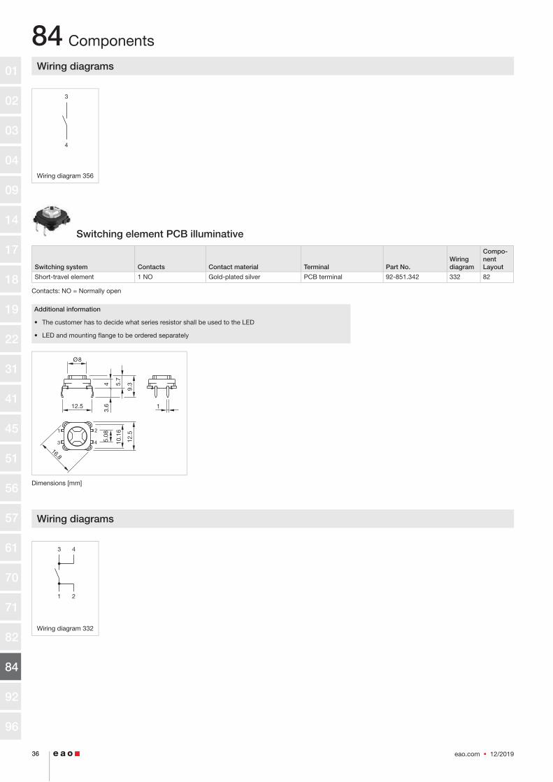
Switching element PCB illuminative
Switching system Contacts Contact material Terminal Part No. Wiring diagram
Compo-nent Layout
Short-travel element 1 NO Gold-plated silver PCB terminal 92-851.342 332 82
Contacts: NO = Normally open
Additional information
• The customer has to decide what series resistor shall be used to the LED
• LED and mounting flange to be ordered separately
Dimensions [mm]
Wiring diagrams
Wiring diagram 332
Components
3
4
3 4
1 2
eao.com § 12/2019 36
84
16.8
Ø8
1
5.08
10.1
6
12.5
3.6
4
9.35.
7
12.5
1
3
2
4
01
02
03
04
09
14
17
18
19
22
31
41
45
51
56
57
61
70
71
82
84
92
96

Component layouts
Component layout 82
Dimensions [mm]A = Switching element with illuminationB = Single LEDC = Drilling plan (component side)D = Hole for switching element, pad max. Ø 2.5 mmE = Hole for LED
Illumination element with plug-in terminal
IP Protection Illumination colour Operating voltage Terminal Part No. Wiring diagram
IP40 Red 12 V DC ±10 % Plug-in terminal 84-8001.2320 351
Yellow 12 V DC ±10 % Plug-in terminal 84-8001.4320 351
Green 12 V DC ±10 % Plug-in terminal 84-8001.5320 351
Blue 12 V DC ±10 % Plug-in terminal 84-8001.6320 351
White 12 V DC ±10 % Plug-in terminal 84-8001.9320 351
Red 24 V DC ±10 % Plug-in terminal 84-8001.2620 351
Amber 24 V DC ±10 % Plug-in terminal 84-8001.3620 351
Yellow 24 V DC ±10 % Plug-in terminal 84-8001.4620 351
Green 24 V DC ±10 % Plug-in terminal 84-8001.5620 351
Blue 24 V DC ±10 % Plug-in terminal 84-8001.6620 351
White 24 V DC ±10 % Plug-in terminal 84-8001.9620 351
Additional information
• LED and built-in resistor included
• Standard version: Cable length 300 mm with insulated ferrule, plug-in terminal 2.8 mm x 0.8 mm
• Other options on request: Customisation of cable and connectors, rear side fully sealed (IP 67)
• Protection degree (rear side): IP 40, upgrade to IP 67 with plug Part No. 84-900 possible. With applica-tions where strong vibrations occure, the plugs may become loose
• Luminosity and wave length variations caused by LED manufacturing processes may cause slight diffe-rences regarding the illumination. The customer has to decide what resistor shall be used to the LED
• Standard version: Cable length 300 mm with insulated ferrule, plug-in terminal 2.8 mm x 0.5 mm
Components
12/2019 § eao.com 37
84
10.16
12.70
10.1
6 C
CC
CB
B
1
34
2K
A
Ø1.0 (2x)
Ø1.3 (4x)
D
E
B
A C
01
02
03
04
09
14
17
18
19
22
31
41
45
51
56
57
61
70
71
82
84
92
96

Wiring diagrams
Wiring diagram 351
Illumination element with flat ribbon cable
IP Protection Illumination colour Operating voltage Terminal Part No. Wiring diagram
IP40 Red 12 V DC ±10 % Flat ribbon cable 84-8001.2340 351
Yellow 12 V DC ±10 % Flat ribbon cable 84-8001.4340 351
Green 12 V DC ±10 % Flat ribbon cable 84-8001.5340 351
White 12 V DC ±10 % Flat ribbon cable 84-8001.9340 351
Red 24 V DC ±10 % Flat ribbon cable 84-8001.2640 351
Amber 24 V DC ±10 % Flat ribbon cable 84-8001.3640 351
Yellow 24 V DC ±10 % Flat ribbon cable 84-8001.4640 351
Green 24 V DC ±10 % Flat ribbon cable 84-8001.5640 351
Blue 24 V DC ±10 % Flat ribbon cable 84-8001.6640 351
White 24 V DC ±10 % Flat ribbon cable 84-8001.9640 351
Additional information
• LED and built-in resistor included
• Standard version: Cable length 300 mm with insulated ferrule, plug-in terminal 2.8 mm x 0.8 mm
• Other options on request: Customisation of cable and connectors, rear side fully sealed (IP 67)
• Protection degree (rear side): IP 40, upgrade to IP 67 with plug Part No. 84-900 possible. With applica-tions where strong vibrations occure, the plugs may become loose
• Luminosity and wave length variations caused by LED manufacturing processes may cause slight diffe-rences regarding the illumination. The customer has to decide what resistor shall be used to the LED
Wiring diagrams
Wiring diagram 351
Components
X1–
X2+
X1–
X2+
eao.com § 12/2019 38
84 01
02
03
04
09
14
17
18
19
22
31
41
45
51
56
57
61
70
71
82
84
92
96

Illumination element bi-colour
IP Protection Illumination colour Operating voltage Terminal Part No. Wiring diagram
IP40 Yellow / Green 24 V AC/DC ±10 % Plug-in terminal 84-8005.7620 352
Red / Green 24 V AC/DC ±10 % Plug-in terminal 84-8005.8620 353
IP67 Yellow / Green 24 V AC/DC ±10 % Flat ribbon cable 84-8005.7640 352
Red / Green 24 V AC/DC ±10 % Flat ribbon cable 84-8005.8640 353
Additional information
• LED and built-in resistor included
• Standard version: Cable length 300 mm with insulated ferrule, plug-in terminal 2.8 mm x 0.8 mm
• Other options on request: Customisation of cable and connectors, rear side fully sealed (IP 67)
• Best illumination level will be reached with aluminium lens with spot, Part No. 84-7215.x00 and 84-7211.x00
• Protection degree (rear side): IP 40, upgrade to IP 67 with plug Part No. 84-900 possible. With applica-tions where strong vibrations occure, the plugs may become loose
• Cabel connection IP 67, rear side fully sealed. The illumination element of the cable version cannot be disconnected from the actuator any longer
• Luminosity and wave length variations caused by LED manufacturing processes may cause slight diffe-rences regarding the illumination. The customer has to decide what resistor shall be used to the LED
Wiring diagrams
Wiring diagram 352 Wiring diagram 353
Components
X2+X3+ X1– +24 V+24 V 0 V
12/2019 § eao.com 39
84 01
02
03
04
09
14
17
18
19
22
31
41
45
51
56
57
61
70
71
82
84
92
96

Switching element Halo Compact
Operating vol-tage
Operation current
Switching sys-tem
Con-tacts
Contact ma-terial
Illumination colour Terminal Part No.
Wiring diagram
Compo-nent Layout
24 V DC ±10 %
80 mA Short-travel ele-ment
1 NO Gold-plated silver
Red Soldering / Plug-in ter-minal
84-8716.2620 439 103
80 mA Short-travel ele-ment
1 NO Gold-plated silver
Yellow Soldering / Plug-in ter-minal
84-8716.4620 439 103
80 mA Short-travel ele-ment
1 NO Gold-plated silver
Green Soldering / Plug-in ter-minal
84-8716.5620 439 103
80 mA Short-travel ele-ment
1 NO Gold-plated silver
Blue Soldering / Plug-in ter-minal
84-8716.6620 439 103
80 mA Short-travel ele-ment
1 NO Gold-plated silver
White Soldering / Plug-in ter-minal
84-8716.9620 439 103
80 mA Short-travel ele-ment
1 NO Gold-plated silver
Red / Green Soldering / Plug-in ter-minal
84-8716.8620 439 103
Contacts: NO = Normally open
Additional information
• Preconfigured light sequences see Technical data
• Integrated electronig switch for latching function (High-Side-Switch)
Dimensions [mm]
Wiring diagrams
Wiring diagram 439
Components
+24 V
0 V
eao.com § 12/2019 40
84 Ø
24.9
6 max.
2 22.5 8.6
31.9
01
02
03
04
09
14
17
18
19
22
31
41
45
51
56
57
61
70
71
82
84
92
96
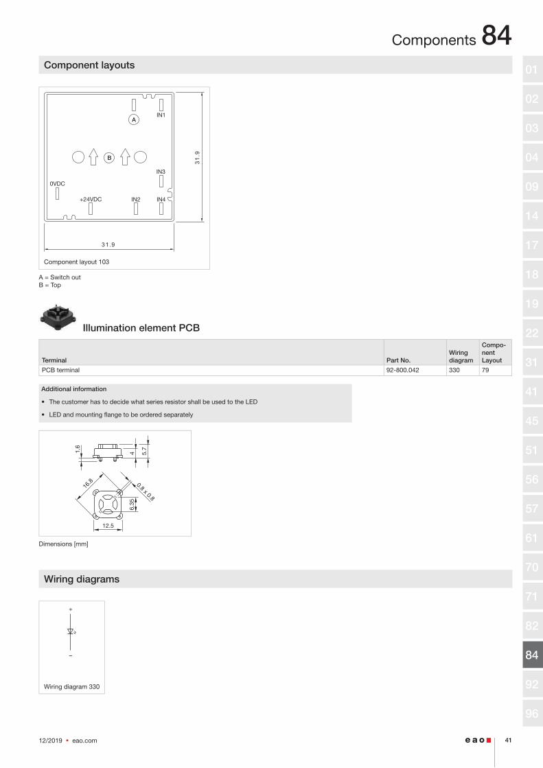
Component layouts
Component layout 103
A = Switch outB = Top
Illumination element PCB
Terminal Part No. Wiring diagram
Compo-nent Layout
PCB terminal 92-800.042 330 79
Additional information
• The customer has to decide what series resistor shall be used to the LED
• LED and mounting flange to be ordered separately
Dimensions [mm]
Wiring diagrams
Wiring diagram 330
Components
–
+
12/2019 § eao.com 41
84
IN1
0VDC
+24VDC
IN3
IN2 IN431
.9
31.9
B
A
4 5.7
6.35
12.5
16.8
1.6
0.8 x 0.8
01
02
03
04
09
14
17
18
19
22
31
41
45
51
56
57
61
70
71
82
84
92
96
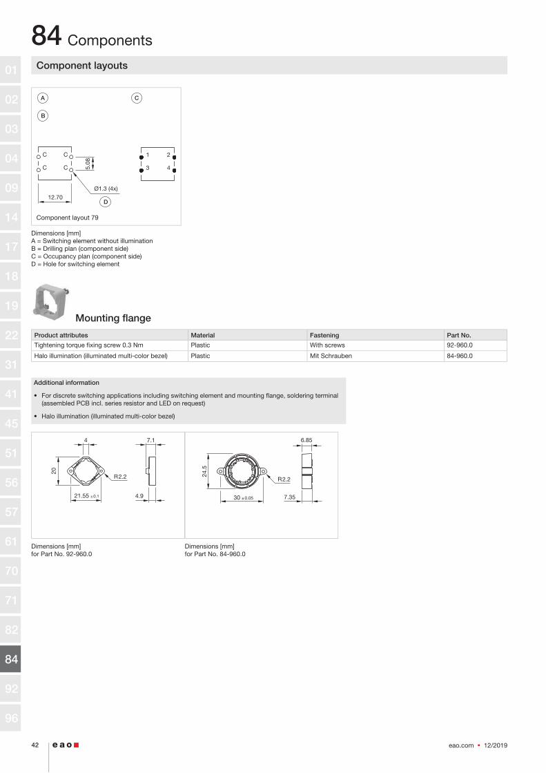
Component layouts
Component layout 79
Dimensions [mm]A = Switching element without illuminationB = Drilling plan (component side)C = Occupancy plan (component side)D = Hole for switching element
Mounting flange
Product attributes Material Fastening Part No.
Tightening torque fixing screw 0.3 Nm Plastic With screws 92-960.0
Halo illumination (illuminated multi-color bezel) Plastic Mit Schrauben 84-960.0
Additional information
• For discrete switching applications including switching element and mounting flange, soldering terminal (assembled PCB incl. series resistor and LED on request)
• Halo illumination (illuminated multi-color bezel)
Dimensions [mm] for Part No. 92-960.0
Dimensions [mm] for Part No. 84-960.0
Components
eao.com § 12/2019 42
84
12.70
C
C
C
C
1
3
2
4
Ø1.3 (4x)
5.08
D
B
A C
20
7.14
4.9
R2.2
21.55 ±0.1
24.5
7.35
6.85
30
R2.2
±0.05
01
02
03
04
09
14
17
18
19
22
31
41
45
51
56
57
61
70
71
82
84
92
96

Front side
Legend frame
Dimensions Material Colour Surface Mounting type Part No.
30 mm x 50 mm Aluminium Black anodised adhesive 61-9980.0
Additional information
• For devices with front dimension Ø 25 mm, flush design
• The colour of anodised aluminium parts can vary due to technical production reasons
Dimensions [mm]
Legend plate
Product attributes Dimensions Material Colour Surface Mounting type Part No.
For legend frame Part No.704.968.2 and 704.968.3 14.5 mm x 23.5 mm Aluminium Nature anodised adhesive 704.968.0
14.5 mm x 23.5 mm Aluminium Black anodised adhesive 704.968.1
Additional information
• The colour of anodised aluminium parts can vary due to technical production reasons
Accessories
12/2019 § eao.com 43
84
14.5
23.5
4Ø
25
30 0 -0.1
50±0
.3
35±0
.3
01
02
03
04
09
14
17
18
19
22
31
41
45
51
56
57
61
70
71
82
84
92
96

Emergency stop legend
Dimensions Material Colour Mounting cut-out Marking Part No.
Ø 60 mm Plastic Yellow Ø 22.3 mm NOT AUS 704.963.5
Plastic Yellow Ø 22.3 mm EMERGENCY STOP 704.963.6
Plastic Yellow Ø 22.3 mm ARRET D'URGENCE 704.963.7
Plastic Yellow Ø 22.3 mm NOT HALT 704.963.8
Plastic Yellow Ø 22.3 mm EN ISO 13850 symbol 704.963.9
Ø 90 mm Plastic Yellow Ø 22.3 mm NOT AUS 704.963.0
Plastic Yellow Ø 22.3 mm EMERGENCY STOP 704.963.1
Plastic Yellow Ø 22.3 mm ARRET D'URGENCE 704.963.2
Plastic Yellow Ø 22.3 mm NOT HALT 704.963.3
Plastic Yellow Ø 22.3 mm EN ISO 13850 symbol 704.963.4
Additional information
• Front panel thickness 3 mm max.
Blind plug
Dimensions Material Colour Mounting cut-out Part No.
Ø 25 mm Plastic Black Ø 25 mm 61-9453.0
Ø 36 mm Plastic Black Ø 30.5 mm 704.964.8
Additional information
• Please note that bigger minimum distances are necessary
Dimensions [mm] for Part No. 61-9453.0
Dimensions [mm] for Part No. 704.964.8
Protective cap
Product attributes Material Colour Optics Part No.
For front bezel Ø 25 mm Silicone Colourless transparent 84-9103.7
Additional information
• For flat lens profil only
• When using the front protection cover the external sealing in the actuator has to be removed
Accessories
eao.com § 12/2019 44
84
Ø36
.2
Ø35
.6
2.6 14
2 … 6
01
02
03
04
09
14
17
18
19
22
31
41
45
51
56
57
61
70
71
82
84
92
96

Protection cover
Dimensions Material Colour Part No.
Ø 36 mm Plastic Black 84-916
Additional information
• When mounting the protective cover 84-916 make sure that the USB adapter is mounted in center positi-on.
Dimensions [mm]
E stop protective shroud
Dimensions Material Colour Marking Part No.
Ø 50 mm Plastic Yellow 84-902
Plastic Yellow NOT - AUS 84-902A
Plastic Yellow EMERGENCY STOP 84-902B
Plastic Yellow NOT - HALT 84-902D
Ø 45 mm Metal Yellow 84-909
Ø 50 mm Plastic Yellow 84-906
Additional information
• Front panel thickness 1 … 3 mm
• With anti-twist device
• When using a protective shroud the e-stop or stop-switch has to be turned by 180° to be mounted. See dimensional drawing
• The protection shroud Part No. 84-909 is not suitable for a proper use of emergency-stop. It can obstruct a spontaneous operation of the emergency-stop switch
• This shroud Part No. 84-906 is not compliant to EN ISO 13850. There are no restrictions when combined with stop switches.
Dimensions [mm] for Part No. 84-902, 84-902A84-902B, 84-904C
Dimensions [mm] for Part No. 84-909
Dimensions [mm] for Part No. 84-906
Accessories
12/2019 § eao.com 45
84
95.84Ø 40
3.7
3.7
Ø22.5
11
1.5
1.8
Ø50
.2
Ø31
.8
Ø22.5
26
1
2.5
Ø45
Ø37
Ø22.5
37.6
Ø50
01
02
03
04
09
14
17
18
19
22
31
41
45
51
56
57
61
70
71
82
84
92
96

USB socket
Material Colour Part No.
Plastic Black 84-3103.0000.1
Black 84-3103.0000.2
Dimensions [mm]
Accessories
www.eao.com
Follow us.We are on LinkedIn!EAO creates possibilities. Since 1947.
Come take a look at our LinkedIn pro� le today! Be sure to give us a follow so that you can fully interact with us.
https://www.linkedin.com/company/eao/
eao.com § 12/2019 46
84
2
37.5 600/1000
Ø 3
0.1
Ø 2
8.3
Ø 2
8.3
Ø 3
4.75
±0.
25
±0.
25
01
02
03
04
09
14
17
18
19
22
31
41
45
51
56
57
61
70
71
82
84
92
96

Rear side
Adaptor reducing to 25 mm
Product attributes Material Colour Part No.
For housing, pole mounting 35 mm dia. Plastic Yellow 84-9300.4
Plastic Grey 84-9300.8
Dimensions [mm]
Adaptor reducing to 30 mm
Product attributes Material Colour Part No.
For housing, pole mounting 35 mm dia. Plastic Yellow 84-9700.4
Plastic Grey 84-9700.8
Dimensions [mm]
Flat receptacle
Product attributes Material Part No.
2.8 x 0.8 mm plug-in terminal Metal 84-9420
Insulation sleeve
Product attributes Material Part No.
For flat receptacle 2.8 mm Plastic 31-929
Accessories
12/2019 § eao.com 47
84
20.5
111
Ø4.
8 Ø25
98 ±0.4
111
20.5
Ø30
Ø4.
8
98 ±0.4
01
02
03
04
09
14
17
18
19
22
31
41
45
51
56
57
61
70
71
82
84
92
96

PCB plug-in base
Dimensions Material Terminal Pins Part No.
Compo-nent Layout
20.3 mm x 8.3 mm x 15.8 mm Metal / plastic PCB terminal Axial 84-920 102
Dimensions [mm]
Component layouts
Component layout 102
Dimensions [mm]A = Drilling plan (component side)B = Centre from switchC = Anti-twist protectionD = Pins for contacts/LEDE = Positioning hole
Plug
Material Part No.
Plastic 84-900
Additional information
• For back protection IP67 of switching elements and illumination elements. Two plugs are nessecary per element
Accessories
eao.com § 12/2019 48
84
2.9
1.6
15.8 8.3 0 -0.2
20.3
DE
B
A
C
01
02
03
04
09
14
17
18
19
22
31
41
45
51
56
57
61
70
71
82
84
92
96

Mounting
Enclosure
Product attributes Dimensions Material Colour IP Protection Part No.
With mounting cut-out 1 x Ø 22.3 mm, with anti-twist device
94 mm x 81 mm x 94 mm Plastic Grey IP66 704.945.1
With mounting cut-out 2 x Ø 22.3 mm, with anti-twist device
130 mm x 81 mm x 94 mm Plastic Grey IP66 704.945.2
With mounting cut-out 3 x Ø 22.3 mm, with anti-twist device
180 mm x 81 mm x 94 mm Plastic Grey IP66 704.945.3
With mounting cut-out 4 x Ø 22.3 mm, with anti-twist device
180 mm x 110 mm x 182 mm Plastic Grey IP66 704.945.4
With mounting cut-out 6 x Ø 22.3 mm, with anti-twist device
180 mm x 110 mm x 182 mm Plastic Grey IP66 704.945.5
Bottom grey similar RAL 7035; cover lead-sealable, yellow similar RAL 1004
65 mm x 57 mm x 65 mm Plastic IP66 84-910
Dimensions [mm] for Part No. 704.945.1, 704.945.2, 704.945.3, 704.945.4, 704.945.5
Dimensions [mm] for Part No. 84-910
Fixing nut
Product attributes Dimensions Material Colour Part No.
For limited-space applications Ø 28 mm Plastic Black 84-905
Standard delivery Ø 30 mm Plastic Black 84-908
Ø 30 mm Plastic Black 84-901
Dismantling tool
Product attributes Material Part No.
For dismantling switching elements or lenses Metal / plastic 84-918
Accessories
12/2019 § eao.com 49
84
B
LH
2.5
57 2565
65
2.5
01
02
03
04
09
14
17
18
19
22
31
41
45
51
56
57
61
70
71
82
84
92
96

Housing pole mounting 35 mm
Product attributes Material Colour Part No.
Please note: The cut-out of the pole must read min. 22 mm and needs to be aligned with the switch
Plastic Yellow 84-9500.4
Plastic Traffic blue 84-9500.6A
Plastic Grey 84-9500.8
Additional information
• Screws are not contained in the scope of supply
Dimensions [mm]
Housing pole mounting 38 mm
Product attributes Material Colour Part No.
Please note: The cut-out of the pole must read min. 22 mm and needs to be aligned with the switch
Plastic Yellow 84-9600.4
Plastic Grey 84-9600.8
Additional information
• Screws are not contained in the scope of supply
Dimensions [mm]
Accessories
eao.com § 12/2019 50
84
Ø4.
8
111
31
38.7
Ø35
50
98
Ø22.5
±0.4
Ø4.
8
110.538
31
42.5
Ø38
Ø22.5
98 ±0.4
01
02
03
04
09
14
17
18
19
22
31
41
45
51
56
57
61
70
71
82
84
92
96

Housing wall mounting
Product attributes Material Colour Part No.
Please note: The cut-out of the pole must read min. 22 mm and needs to be aligned with the switch
Plastic Yellow 84-9800.4
Plastic Grey 84-9800.8
Additional information
• Screws are not contained in the scope of supply
Dimensions [mm]
Cable gland
Product attributes Material Colour IP Protection Thread Part No.
With traction relief Plastic Grey IP68 M16 x 1.5 mm 61-9481.6
Plastic Grey IP68 M20 x 1.5 mm 704.945.6
Mounting tool
Product attributes Dimensions Material Part No.
For tightening or loosening the fixing nut, for emer-gency-stop and stop-switch
Metal 84-996
For tightening or loosening of the fixing nut Ø 22 mm
Ø 22 mm Metal 84-997
Accessories
12/2019 § eao.com 51
84
Ø4.
8
110 36
3131
Ø22.5
98 ±0.4
01
02
03
04
09
14
17
18
19
22
31
41
45
51
56
57
61
70
71
82
84
92
96

Technical data
Emergency-stop
Switching system
The double-break switching system can be supplied for thefollowing switching functions:1 Normally closed, 2 Normally closed, 1 Normally closed + 1 Normally open.The Normally closed contacts have forced opening according to EN 60947-5-5
Material
Connection cable
Plastic, operating temperature up to + 65 °C
Mushroom-head cap
Plastic, as per UL 94 V0
Actuator housing
Plastic, as per UL 94 V0
Material of contact
Silver alloy gold plated
Mechanical characteristics
Front panel thickness
Standard 1 … 4 mmwith emergency stop protective shroud Part No. 84-902 1 … 3 mm
Mounting cut-outs
Ø 22.3 mm as per EN IEC 60947-5-1 with anti-twist device
Terminals
Soldering terminals 2.8 mm x 0.5 mm (solderable), CuSn6 tin-platedFlat ribbon cable 2-, 4-, or 6-poles 0.35 mm² (AWG 22)
Tightening torque
Fixing nut 0.8 Nm
Actuating force
17 N ± 4 N
Actuating travel
Approx. 5 mm
Mechanical lifetime
250 000 cycles of operations
Electrical characteristics
Standards
The devices comply with: EN IEC 60947-5-1, EN IEC 60947-5-5 (emergency stop), DIN EN ISO 13850, EN IEC 60204
Illumination
LED red with pole reversal, constant current sourceOperation Voltage 5 VDC … 30 VDCCurrent consumption 9.7 mA … 12.4 mA
Rated Operational Voltage Ue
250 VAC, as per EN IEC 60947-1
Rated Insulation Voltage Ui
250 V, as per EN IEC 60947-1
Rated Impulse Withstand Voltage Uimp
4 kV, as per EN IEC 60947-1
Electrical life
50 000 cycles of operations(inductive cosφφ 0,95) as per EN IEC 60947-5-1
Air thermal Ith
5 A (plug in)3 A (cable leads
Switching voltage and switching current
Switch rating AC with silver contact (gold plated), service category AC-15, as per EN IEC 60947-5-1
Voltage 120 VAC 240 VACCurrent 3 A 1.5 A
Switch rating DC for silver contact (gold plated), service category DC-13, as per EN IEC 60947-5-1
NO contacts NC contacts NO/NC contacts(48 VA) (60 VA) 12 VDC / 2.0 A 12 VDC / 2.5 A 125 VDC / 0.22 A24 VDC / 2.0 A 24 VDC / 2.5 A 250 VDC / 0.11 A48 VDC / 1.0 A 48 VDC / 1.25 A 60 VDC / 0.8 A 60 VDC / 1.0 A
Recommended minimum operating data
Silver contacts (gold plated)
Voltage 1 VAC / DCCurrent 1 mA
Electric strength
500 VAC, 50 Hz, 1 minute, as per DIN IEC 60512-2
Rated conditional short-circuit current
1000 A, type of short-circuit unit 6 A gG, as per EN IEC 60947-5-1
Protection class
Class II, as per EN IEC 60947-5
eao.com § 12/2019 52
8401
02
03
04
09
14
17
18
19
22
31
41
45
51
56
57
61
70
71
82
84
92
96

Technical dataOvervoltage category
III, as per EN IEC 60947-1
Degree of pollution
3, as per EN IEC 60947-1
Ambient conditions
Storage temperature
-25 °C … +80 °C
Operating temperature
-25 °C … +65 °C
Front protection
IP65 front side, as per EN IEC 60529IP66 front side, as per EN IEC 60529IP67 front side, as per EN IEC 60529IP20 (cable lead connection)
Impact resistance
IK07, as per IEC 62262
Shock resistance
(semi-sinusoidal)Max. 150 m / s², pulse width 11 ms, 3-axis, as per EN IEC 60068-2-27
Vibration resistance
(sinusoidal)Max. 50 m / s² at 10 Hz … 500 Hz, 10 cycles, 3-axis, as per EN IEC 60068-2-6
Climate resistance
Damp heat, cyclic96 hours, + 25 °C /97 %, + 55 °C / 93 % relative humidity, as per EN IEC 60068-2-30Damp heat, steady56 days, + 40 °C / 93 % relative humidity, as per EN IEC 60068-2-78
Dry heat96 hours, + 65 °C, as per EN IEC 60068-2-2
Low temperature96 hours, – 25 °C, as per EN IEC 60068-2-1
Saline mist96 hours, + 35 °C in chemical solution NaCl, as per EN IEC 60068-2-11
Approvals
Approbations
CB (IEC 60947-5-1, IEC 60947-5-5)UL NISDCCC (pending)
Declaration of conformity
CE2006 / 42 / EC (MD)2011 / 65 / EC (RoHS)
Switching element illuminated pushbutton
Switching system
Short-travel switching system with 2 independent contact points and tactile operation.Guarantees reliable switching even of very light loads.Fitted with 1 normally open contact.
Material
Connection cable
Plastic, short-time heat-resistant up to 105 °C
Material of contact
Silver alloy gold plated
Switching element
Plastic, as per UL 94 V0 and Plastic, as per UL 94 HB
Mechanical characteristics
Terminals
Plug-in terminals 2.8 mm x 0.8 mm (solderable)Flat ribbon cable 0.5 mm²PCB terminal
Actuating force
4.0 N ±0.2 N
Tightening torque
Fixing screw mounting flange 0.4 Nm
Actuating travel
~ 0.5 mm
Resistance to heat of soldering
250 °C, 3 s (PCB assembly)320 °C, 3 s (when using a soldering iron)
12/2019 § eao.com 53
8401
02
03
04
09
14
17
18
19
22
31
41
45
51
56
57
61
70
71
82
84
92
96

Technical dataMechanical lifetime
≥ 1 million cycles of operations
Electrical characteristics
Illumination
Single-Chip LED, green, orange, red, yellow, white and blue
Operation Voltage 12 VDC 24 VDCCurrent consumption 10 mA 10 mA
Electrical life
as per EN IEC 60512-5
5 million cycles of operation 24 VAC, 50 mA at 480 Ω 5 million cycles of operation 24 VAC, 100 mA at 240 Ω 2 million cycles of operation 42 VAC, 50 mA at 840 Ω 2 million cycles of operation 42 VAC, 100 mA at 420 Ω 300 000 cycles of operation 42 VAC, 100 mA at cosφφ 0.4 250 000 cycles of operation 42 VAC, 200 mA at cosφφ 0.395 1 million cycles of operation 12 VDC, 250 mA at 48 Ω 1 million cycles of operation 24 VDC, 50 mA at 480 Ω 1 million cycles of operation 24 VDC, 100 mA at 240 Ω 5 million cycles of operation 42 VDC, 25 mA at 1680 Ω 1.5 million cycles of operation 42 VDC, 50 mA at 840 Ω 100 000 cycles of operation 42 VDC, 100 mA at 420 Ω 500 000 cycles of operation 24 VDC, 200 mA at L/R = 30 ms 300 000 cycles of operation 42 VDC, 100 mA at L/R = 30 ms 100 000 cycles of operation 42 VDC, 200 mA at L/R = 30 ms
Switching voltage and switching current
Voltage 50 mVAC/DC … 42 VAC/DCCurrent 10 uA … 100 mAPower max. 2 W
Electric strength
500 VAC, 50 Hz, 1 minute, as per DIN IEC 60512-2
Ambient conditions
Storage temperature
– 40 °C ... + 85 °C
Operating temperature
– 25 °C ... + 70 °C
Protection degree
Back protection:IP40, standard versionIP67, fully sealed version, with mounted actuator only.
Shock resistance
(semi-sinusoidal)Max. 100 m / s², pulse width 11 ms, 3-axis, as per EN IEC 60068-2-27
Vibration resistance
(sinusoidal)Max. 50 m / s² at 10 Hz … 500 Hz, 10 cycles, 3-axis, as per EN IEC 60068-2-6
Switching element Halo Compact
Switch configuration
A complete switch requires a halo compact programmable switch actuator body (transparent) and a lens. If the switch needs lens illumination in addition then a translucent plastic lens or aluminium lens with a window is required.
Use Halo Compact with illuminated pushbutton actuator (Part No. 84-1081.7) or with the indicator actuator (Part No. 84-0080.7).
The illumination style is selected by the connection of 24V to the pins.
Material
Housing
PlasticPlastic (sealing compound)
Material of contact
Silver alloy, gold-platedThe materials used comply with the high EAO standardsrelating to quality, functional safety, service life and design.
Mechanical characteristics
Terminals
Soldering / plug-in terminals 2.8 mm x 0.8 mm (solderable)
Actuating force
4.0 N ± 0.2 N(measured at the lens)
Actuating distance
~ 0.5 mm
Mechanical lifetime
≥ 1 million cycles of operation
eao.com § 12/2019 54
8401
02
03
04
09
14
17
18
19
22
31
41
45
51
56
57
61
70
71
82
84
92
96

Technical dataElectrical characteristics
Switching element
Short-travel snap-action switching system with two independent contact points and tactile operation.
Number of contacts: one normal open contact
OutputElectronic high-side switch
Pre-configured light sequences- Full illumination - Blinking (interval: 1 second)- Rotating/chasing (one full rotation per second)- Process (changeover a group of 4 LEDs per second)
Special featureIntegrated electronic switch for maintained action (High-side switch)
Operating voltage
24 VDC ± 10 %Max. 100 mA
Current consumption
< 80 mA
LED-colours
All versions available with eight SMD LEDs for halo illumination plus one single LED (3mm) for central illumination. The following variants are available:
8 x red LEDs + 1 white single LED8 x green LEDs + 1 white single LED8 x yellow LEDs + 1 white single LED8 x white LEDs + 1 white single LED8 x blue LEDs + 1 white single LED8 x red /green bi-colour LEDs + 1 white single LED
Ambient conditions
Storage temperature
– 40 °C ... + 85 °C
Operating temperature
– 25 °C ... + 70 °C
Degree of protection
IP67 front side(with actuator Part No. 84-1081.7 and 84-0080.7)
Shock resistance
(semi-sinusoidal)Max. 100 m / s², pulse width 6 ms, 3-axis, as per EN IEC 60068-2-27
Vibration resistance
(sinusoidal)Max. 50 m / s² at 10 Hz … 500 Hz, 10 cycles, 3-axis, as per EN IEC 60068-2-6
Approvals
Conformities
CE2014 / 30 / EU (EMC)2011 / 65 / EC (RoHS)
Light sequences central LED IN1 IN2 IN3
not illuminated illuminated
1 – 0 VDC 0 VDC 0 VDC
2 – + 24 VDC 0 VDC 0 VDC
3 – 0 VDC + 24 VDC 0 VDC
4 – + 24 VDC + 24 VDC 0 VDC
– 5 0 VDC 0 VDC + 24 VDC
– 6 + 24 VDC 0 VDC + 24 VDC
– 7 0 VDC + 24 VDC + 24 VDC
– 8 + 24 VDC + 24 VDC + 24 VDC
* Functionen of light sequence:1/5 = Full illuminiation2/6 = Blink3/7 = Rotation4/8 = Process
12/2019 § eao.com 55
8401
02
03
04
09
14
17
18
19
22
31
41
45
51
56
57
61
70
71
82
84
92
96

Technical data
EAO reserves the right to alter specifications without further notice.
Actuator
Material
Lens
Plastic, as per UL 94 V2 or Aluminium anodised
Actuator housing
Plastic, as per UL 94 V0 or Aluminium anodised
Mechanical characteristics
Tightening torque
Fixing nut max. 80 Ncm
Actuating force
4.0 N ± 0.2 N (measured at the lens)
Actuating travel
1.2 mm
Mechanical lifetime
≥ 1 million cycles of operation
Electrical characteristics
Electrostatic breakdown value
Plastic case ≥ 15 kVAluminium case ≥ 5 kVas per IEC 61000-4-2, mounted in plastic front panel
Ambient conditions
Storage temperature
– 40 °C ... + 85 °C
Operating temperature
– 25 °C ... + 70 °C
Protection degree
IP 67 and IP40 front side, as per EN IEC 60529
Climate resistance
Damp heat, cyclic96 hours, + 25 °C / 97 %, +55 °C / 93 % relative humidity, as per EN IEC 60068-2-30
Damp heat, state56 days, + 40 °C / 93 % relative humidity, as per EN IEC 60068-2-78
Rapid change of temperature100 cycles, – 40 °C … + 80 °C, as per EN IEC 60068-2-14
Approvals
Approbations
EBC (TSI / PRM)NFF
Conformities
CE2011 / 65 / EC (RoHS)
eao.com § 12/2019 56
8401
02
03
04
09
14
17
18
19
22
31
41
45
51
56
57
61
70
71
82
84
92
96

Application guidelines
Suppressor circuits
Note for soldering
When switching inductive loads such as relays, DC motors, and DC solenoids, it is always important to absorb surges (e. g. with a diode) to protect the contacts. When these inductive loads are switched off, a counter emf can severely damage switch contacts and greatly shorten lifetime.
Fig. 1 shows an inductive load with a free-wheeling diode connec-ted in parallel. This free-wheeling diode provides a path for the inductor current to flow when the current is interrupted by the switch. Without this free-wheeling diode, the voltage across the coil will be limited only by dielectric breakdown voltages of the circuit or parasitic elements of the coil. This voltage can be kilo-
Process parameter for wave solderingBasic specification for wave soldering J-STD 75 W4C.
Maximum temperature on the component side (Temp 2):(Temperature must not exceed during the entire processing)
Preheating phase (t1 … t2):Ramp up:
Ramp up to maximum temperature (t2 … t3):
Maximum temperature on the soldering side (Temp 3):Maximum time of soldering process (t3 … t4):
Ramp down at 170 °C:
120 °C
70 … 120 sectyp.+ 1 °C / sec
not defined
250 °C3 sec
typ. – 2 °C/sec
volts in amplitude even when nominal circuit voltages are low (e. g. 12 VDC) see Fig. 2.
The free-wheeling diode should be chosen so that the reverse breakdown voltage is greater than the voltage driving the induc tive load. The DC blocking voltage (VR) of the free-wheeling diode can be found in the datasheet of a diode. The forward current should be equal or greater than the maximum current flowing through the load.
To get an efficient protection, the free-wheeling diode must be connected as
close as possible to the inductive load!
Several hundredto several
thousend volts
ON OFF
0
e = Ldidt__
VDC
Switch
Free-wheelingdiode
Inductiveload
Counter EMFover load without free-wheeling diode
Fig. 2
Switching with inductive load
Fig. 1
+_
12/2019 § eao.com 57
8401
02
03
04
09
14
17
18
19
22
31
41
45
51
56
57
61
70
71
82
84
92
96

Application guidelinesTemperature curve wave soldering
Green curve: Temperature on the component side of the pcbRed curve: Temperature on the soldering side of the pcb
Room temperature: Temp 1
Preheating: Temperature process = Temp 1 … Temp 2 Process time = t1 … t2
Ramp up to soldering temperature: Process time = t2 … t3
Soldering phase: Temperature process = Temp 3 Process time = t3 … t4
Iron soldering
Basic specification for iron soldering IEC 60068-2-20
Maximum temperature at tip of iron: 320 °CMaximum soldering time: 3 sec
Cleaning/Lacquering
The switching elements are not sealed. Cleaning up the PCB may damage the contacts in the switching elements. For this reason, the following points should be noted:– When soldering make sure that the flux does not pass on the upper side of the PCB.– When cleaning the PCB with detergents ensure that no dust or other debris may get inside of the switching elements.– Ensure that no lacquer penetrates into the interior of the switching element when lacquering the PCB.
Storage of components
To obtain the optimum solderability of the components, the fol-lowing points should be noted during storage:– Do not store components in locations with high temperature or humidity.– Do not expose components to corrosive gases.– Avoid direct sunlight for a long period.
eao.com § 12/2019 58
8401
02
03
04
09
14
17
18
19
22
31
41
45
51
56
57
61
70
71
82
84
92
96

Application guidelines
Arrangement mounting flange for switching- and illumination element, PCB mounting
The arrangement of the mounting flanges and their number is determined by the size of the front panel or PCB. To ensure uni-form, tactile switching, we recommend a layout of the flanges as per adjacent sketch.
For large PCBs with several switching elements we recommend the following procedure:1. Fit the actuator to the front panel.2. Clip the mounting flange to the rear of the intended actuator.3. Screw the PCB with the components soldered to it to the assembled mounting flange.
This arrangement applies to PCBs 1.6 mm thick.
25...
30
25...30
max
. 60
max. 60
Dismantling mounting flange
The tool Part No. 84-998 must be used for removing the mounting flange from the actuator.
Before removing the flange, the PCB fixing srews must be loo-sened.
12/2019 § eao.com 59
8401
02
03
04
09
14
17
18
19
22
31
41
45
51
56
57
61
70
71
82
84
92
96

10-2601.3172S ...........3210-2601.3173S ...........3210-2603.3174S ...........3210-2603.3175S ...........3210-2603.3176S ...........3210-2603.3178S ...........3210-2603.320AL ...........3310-2603.320CL ...........3331-929 ........................4761-9453.0 ...................4461-9481.6 ...................5161-9707.7 ...................3261-9980.0 ...................43704.945.1....................49704.945.2....................49704.945.3....................49704.945.4....................49704.945.5....................49704.945.6....................51704.963.0....................44704.963.1....................44704.963.2....................44704.963.3....................44704.963.4....................44704.963.5....................44704.963.6....................44704.963.7....................44704.963.8....................44704.963.9....................44704.964.8....................44704.968.0....................43704.968.1....................4384-0080.7 ...................1984-0090.7 ...................1784-0090.7 ...................1884-0100.0 ...................1584-0100.0 ...................1684-0200.7 ...................1584-0200.7 ...................1684-1081.7 ...................1084-1091.7 .....................884-1091.7 .....................984-1101.0 .....................484-1101.0 .....................684-1101.0 ...................1184-1101.0 ...................1384-1201.0 .....................484-1201.0 .....................684-1201.0 ...................1184-1201.0 ...................1384-1201.2 .....................484-1201.2 .....................684-1201.2 ...................1184-1201.2 ...................1384-1201.4 .....................484-1201.4 .....................684-1201.4 ...................1184-1201.4 ...................1384-1201.5 .....................484-1201.5 .....................684-1201.5 ...................1184-1201.5 ...................1384-1201.6 .....................484-1201.6 .....................684-1201.6 ...................1184-1201.6 ...................1384-1201.7 .....................484-1201.7 .....................684-1201.7 ...................1184-1201.7 ...................1384-1221.7 .....................584-1221.7 .....................684-1221.7 ...................1284-1221.7 ...................1384-2101.0 .....................484-2101.0 .....................684-2101.0 ...................11
84-8511.2640 .............3484-8511.3320 .............3384-8511.3340 .............3484-8511.3620 .............3384-8511.3640 .............3484-8511.4320 .............3384-8511.4340 .............3484-8511.4620 .............3384-8511.4640 .............3484-8511.5320 .............3384-8511.5340 .............3484-8511.5620 .............3384-8511.5640 .............3484-8511.6320 .............3384-8511.6340 .............3484-8511.6620 .............3384-8511.6640 .............3484-8511.9320 .............3384-8511.9340 .............3484-8511.9620 .............3384-8511.9640 .............3484-8515.7640 .............3584-8515.8640 .............3584-8716.2620 .............4084-8716.4620 .............4084-8716.5620 .............4084-8716.6620 .............4084-8716.8620 .............4084-8716.9620 .............4084-900 ........................4884-901 ........................4984-902 ........................4584-902A ......................4584-902B ......................4584-902D ......................4584-905 ........................4984-906 ........................4584-908 ........................4984-909 ........................4584-910 ........................4984-9103.7 ...................4484-916 ........................4584-918 ........................4984-920 ........................4884-9300.4 ...................4784-9300.8 ...................4784-9420 ......................4784-9500.4 ...................5084-9500.6A .................5084-9500.8 ...................5084-960.0 .....................4284-9600.4 ...................5084-9600.8 ...................5084-9700.4 ...................4784-9700.8 ...................4784-9800.4 ...................5184-9800.8 ...................5184-996 ........................5184-997 ........................5192-800.042 .................4192-851.342 .................3692-960.0 .....................42
84-2101.0 ...................1384-3100.0 ...................1584-3100.0 ...................1684-3103.0000.1 ..........4684-3103.0000.2 ..........4684-5220.0020 .............2384-5220.0040 .............2384-5221.2B20 .............2384-5221.2B40 .............2384-5230.0020 .............2384-5230.0040 .............2384-5231.2B20 .............2384-5231.2B40 .............2384-5240.0020 .............2384-5240.0040 .............2384-5241.2B20 .............2384-5241.2B40 .............2384-5241.8D20 .............2684-5241.8D40 .............2684-5320.0020 .............2384-5320.0040 .............2484-5321.2B20 .............2484-5321.2B40 .............2484-5330.0020 .............2484-5330.0040 .............2484-5331.2B20 .............2484-5331.2B40 .............2484-5340.0020 .............2484-5340.0040 .............2484-5341.2B20 .............2484-5341.2B40 .............2484-5341.8D20 .............2684-5341.8D40 .............2684-6220.0020 .............2084-6220.0040 .............2084-6821.2B20 .............2084-6821.2B40 .............2084-6830.0020 .............2084-6830.0040 .............2084-6831.2B20 .............2084-6831.2B40 .............2084-6840.0020 .............2084-6840.0040 .............2084-6841.2B20 .............2084-6841.2B40 .............2084-7111.200 ...............2984-7111.201 ...............3084-7111.202 ...............3084-7111.203 ...............3084-7111.300 ...............2984-7111.301 ...............3084-7111.400 ...............2984-7111.401 ...............3084-7111.500 ...............2984-7111.501 ...............3084-7111.502 ...............3084-7111.503 ...............3084-7111.600 ...............2984-7111.601 ...............3084-7111.602 ...............3084-7111.603 ...............3084-7111.700 ...............2984-7111.701 ...............3084-7111.702 ...............3084-7111.703 ...............3084-7114.600A .............3284-7115.200 ...............2984-7115.300 ...............2984-7115.400 ...............2984-7115.500 ...............2984-7115.600 ...............2984-7115.700 ...............2984-7121.000 ...............2984-7121.800 ...............2984-7124.000A .............3284-7124.200A .............3284-7125.000 ...............29
84-7125.800 ...............2984-7201.000 ...............3184-7201.200 ...............3184-7201.400 ...............3184-7201.500 ...............3184-7201.600 ...............3184-7201.800 ...............3184-7202.000 ...............3184-7202.000A .............2884-7202.200 ...............3184-7202.200A .............2884-7202.400 ...............3184-7202.400A .............2884-7202.500 ...............3184-7202.500B .............2884-7202.600 ...............3184-7202.600A .............2884-7202.800 ...............3184-7202.800A .............2884-7205.000 ...............3184-7205.000A .............2884-7205.200 ...............3184-7205.200A .............2884-7205.400 ...............3184-7205.400A .............2884-7205.500 ...............3184-7205.500A .............2884-7205.600 ...............3184-7205.600A .............2884-7205.800 ...............3184-7205.800A .............2884-7205.804A .............2884-7205.805A .............2884-7205.806A .............2884-7205.808A .............2884-7211.000 ...............3184-7211.200 ...............3184-7211.400 ...............3184-7211.500 ...............3184-7211.600 ...............3184-7211.800 ...............3184-7215.000 ...............3184-7215.200 ...............3184-7215.400 ...............3184-7215.500 ...............3184-7215.600 ...............3184-7215.800 ...............3184-8001.2320 .............3784-8001.2340 .............3884-8001.2620 .............3784-8001.2640 .............3884-8001.3620 .............3784-8001.3640 .............3884-8001.4320 .............3784-8001.4340 .............3884-8001.4620 .............3784-8001.4640 .............3884-8001.5320 .............3784-8001.5340 .............3884-8001.5620 .............3784-8001.5640 .............3884-8001.6320 .............3784-8001.6620 .............3784-8001.6640 .............3884-8001.9320 .............3784-8001.9340 .............3884-8001.9620 .............3784-8001.9640 .............3884-8005.7620 .............3984-8005.7640 .............3984-8005.8620 .............3984-8005.8640 .............3984-8510.0020 .............3584-8510.0040 .............3584-8511.2320 .............3384-8511.2340 .............3484-8511.2620 .............33
Part No. Page Part No. PagePart No. Page Part No. Page
Index84
eao.com § 12/2019 60