series brake motors - manufacturer of motion control … · brake motors v series clutch &...
TRANSCRIPT
Standard AC MotorsIn
trod
uctio
nIn
du
ctio
nM
oto
rsR
evers
ible
M
oto
rsE
lectrom
agn
etic B
rake Mo
tors
V S
erie
sC
lutc
h &
B
rake M
oto
rsS
yn
ch
ron
ou
s
Mo
tors
Lo
w-S
peed
S
yn
ch
ron
ou
s
Mo
tors
Wate
rtigh
t, D
ust-R
esis
tan
t M
oto
rs
To
rqu
e
Mo
tors
Rig
ht-A
ng
leG
earh
ead
sL
inear H
ea
ds
Bra
ke
Pack
Accesso
ries
Insta
llatio
n
C-213
Standard AC Motors
Torque Motors
Torque Motors
PageORIENTAL MOTOR GENERAL CATALOG 2012/2013
Features C-214 / System Configuration C-217 / Specifications C-219 / Product Line C-218Characteristics C-221 / Dimensions C-222 / Connection Diagrams C-225
C-214
●Additional Information●Technical reference ➜ Page G-1
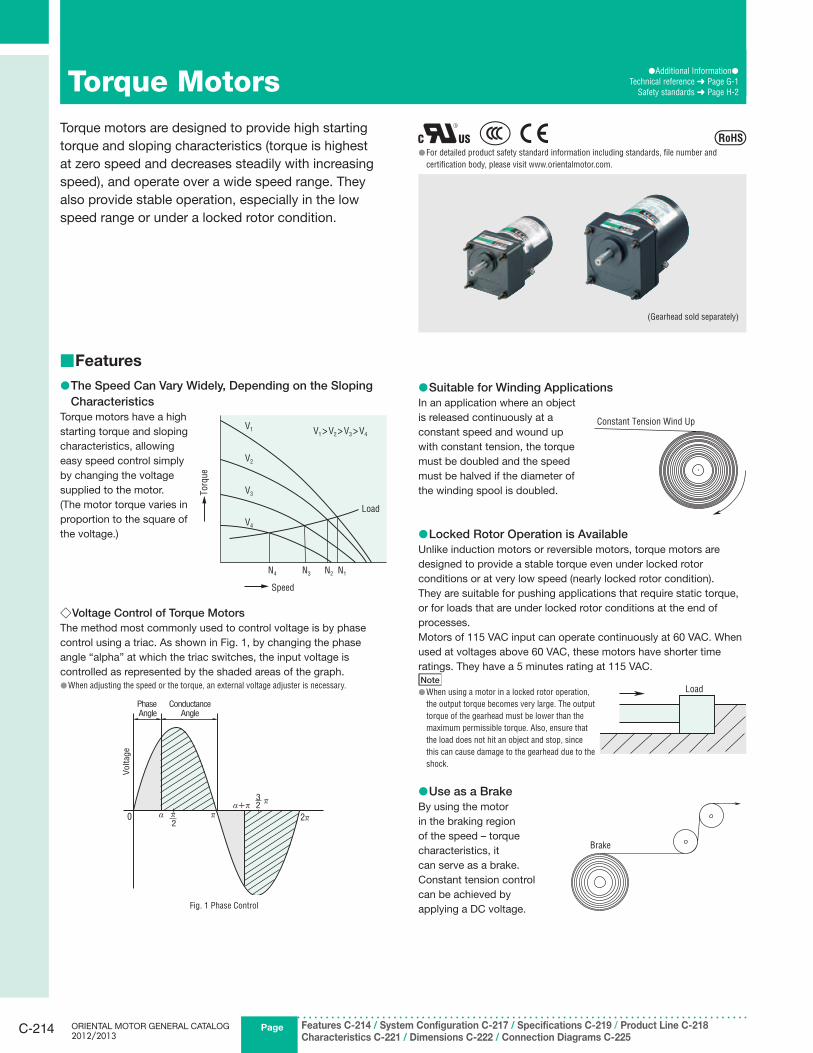
Safety standards ➜ Page H-2Torque MotorsTorque motors are designed to provide high starting
torque and sloping characteristics (torque is highest
at zero speed and decreases steadily with increasing
speed), and operate over a wide speed range. They
also provide stable operation, especially in the low
speed range or under a locked rotor condition.
For detailed product safety standard information including standards, file number and ●certification body, please visit www.orientalmotor.com.
(Gearhead sold separately)
Features ■
The Speed Can Vary Widely, Depending on the Sloping ●Characteristics
Torque motors have a high
starting torque and sloping
characteristics, allowing
easy speed control simply
by changing the voltage
supplied to the motor.
(The motor torque varies in
proportion to the square of
the voltage.)
Voltage Control of Torque Motors ◇The method most commonly used to control voltage is by phase
control using a triac. As shown in Fig. 1, by changing the phase
angle “alpha” at which the triac switches, the input voltage is
controlled as represented by the shaded areas of the graph.
When adjusting the speed or the torque, an external voltage adjuster is necessary. ●
PhaseAngle
ConductanceAngle
Voltage
0 � 2�α+�
α
3 2
�� 2
Fig. 1 Phase Control
Suitable for Winding Applications ●In an application where an object
is released continuously at a
constant speed and wound up
with constant tension, the torque
must be doubled and the speed
must be halved if the diameter of
the winding spool is doubled.
Locked Rotor Operation is Available ●Unlike induction motors or reversible motors, torque motors are
designed to provide a stable torque even under locked rotor
conditions or at very low speed (nearly locked rotor condition).
They are suitable for pushing applications that require static torque,
or for loads that are under locked rotor conditions at the end of
processes.
Motors of 115 VAC input can operate continuously at 60 VAC. When
used at voltages above 60 VAC, these motors have shorter time
ratings. They have a 5 minutes rating at 115 VAC.
Note
When using a motor in a locked rotor operation, ●the output torque becomes very large. The output
torque of the gearhead must be lower than the
maximum permissible torque. Also, ensure that
the load does not hit an object and stop, since
this can cause damage to the gearhead due to the
shock.
Use as a Brake ●By using the motor
in the braking region
of the speed – torque
characteristics, it
can serve as a brake.
Constant tension control
can be achieved by
applying a DC voltage.
N4 N3 N2 N1
V1>V2>V3>V4
V1
V2
V3
V4
Torq
ue
Speed
Load
Constant Tension Wind Up
Load
Brake
CAD DataManuals
www.orientalmotor.com Technical Support
TEL: (800) 468-3982E-mail: [email protected]
Standard AC MotorsIn
trod
uctio
nIn
du
ctio
nM
oto
rsR
evers
ible
M
oto
rsE
lectrom
agn
etic B
rake Mo
tors
V S
erie
sC
lutc
h &
B
rake M
oto
rsS
yn
ch
ron
ou
s
Mo
tors
Lo
w-S
peed
S
yn
ch
ron
ou
s
Mo
tors
Wate
rtigh
t, D
ust-R
esis
tan
t M
oto
rs
To
rqu
e
Mo
tors
Rig
ht-A
ng
leG
earh
ead
sL
inear H
ea
ds
Bra
ke
Pack
Accesso
ries
Insta
llatio
n
C-215
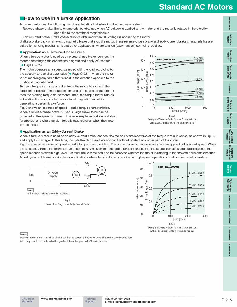
Application as an Eddy-Current Brake ●When a torque motor is used as an eddy-current brake, connect the red and white leadwires of the torque motor in series, as shown in Fig. 3,
and apply DC voltage. At this time, insulate the black leadwire so that it will not contact any other part of the circuit.
Fig. 4 shows an example of speed – brake torque characteristics. The brake torque varies depending on the applied voltage and speed. When
the speed is 0 r/min, the brake torque becomes 0 N·m (0 oz-in). The brake torque increases as the speed increases and stabilizes once the
speed reaches a certain high level. A similar brake force can also be achieved whether the motor is rotating in the forward or reverse direction.
An eddy-current brake is suitable for applications where tension force is required at high-speed operations or at bi-directional operations.
White
BlackDC Power
Supply VDC
R
Line
Red
Note
The black leadwire should be insulated. ●
Fig. 3
Connection Diagram for Eddy-Current Brake
10000 2000 3000
25 VDC 0.52 A
30 VDC 0.63 A
Speed [r/min]
0
0.1
0.2
0.3
0.4
10 VDC 0.21 A
20 VDC 0.42 A
4TK10A-AW2U
15 VDC 0.32 A
10
20
30
40
50
0
Bra
ke T
orq
ue
[N·m
]
Bra
ke T
orq
ue
[oz-
in]
Fig. 4
Example of Speed – Brake Torque Characteristics
with Eddy-Current Brake (Reference values)
Notes
When a torque motor is used as a brake, continuous operating time varies depending on the specific conditions. ●If a torque motor is combined with a gearhead, keep the speed to 2400 r/min or below. ●
How to Use in a Brake Application ■A torque motor has the following two characteristics that allow it to be used as a brake:
Reverse-phase brake: Brake characteristics obtained when AC voltage is applied to the motor and the motor is rotated in the direction
opposite to the rotational magnetic field
Eddy-current brake: Brake characteristics obtained when DC voltage is applied to the motor
Unlike a brake pack or an electromagnetic brake that stop the motor, these reverse-phase brake and eddy-current brake characteristics are
suited for winding mechanisms and other applications where tension (back-tension) control is required.
Application as a Reverse-Phase Brake ●When a torque motor is used as a reverse-phase brake, connect the
motor according to the connection diagram and apply AC voltage.
(➜ Page C-225)
The motor operates at a speed balanced with the load according to
the speed – torque characteristics (➜ Page C-221), when the motor
is not receiving any force that turns it in the direction opposite to the
rotational magnetic field.
To use a torque motor as a brake, force the motor to rotate in the
direction opposite to the rotational magnetic field at a torque greater
than the starting torque of the motor. Then, the torque motor rotates
in the direction opposite to the rotational magnetic field while
generating a certain brake force.
Fig. 2 shows an example of speed – brake torque characteristics.
When a reverse-phase brake is used, a large brake force can be
obtained at the speed of 0 r/min. The reverse-phase brake is suitable
for applications where tension force is required even when the motor
is at standstill.
0
0.05
0.15
0.10
0.20
0.40
0.35
0.30
0.25
10
20
30
40
50
0
Bra
ke T
orq
ue
[N·m
]
Bra
ke T
orq
ue
[oz-
in]
Speed [r/min]
115 VAC
80 VAC
60 VAC
40 VAC
0 500 1000 1500
110 VAC
50 VAC
4TK10A-AW2U
Fig. 2
Example of Speed – Brake Torque Characteristics
with Reverse-Phase Brake (Reference values)
PageORIENTAL MOTOR GENERAL CATALOG 2012/2013
Features C-214 / System Configuration C-217 / Specifications C-219 / Product Line C-218Characteristics C-221 / Dimensions C-222 / Connection Diagrams C-225
C-216
Torque Motors
Features and Types of Gearheads ■
Long Life, Low Noise ● GN-S Gearhead is Available
Adopting innovative technologies and structure, the "long life, low
noise GN-S gearhead" achieves a long rated life of 10000 hours,
twice as long as the level of a conventional gearhead. Also, the
gearhead is designed for low noise.
Details of long life, low-noise ● GN-S gearhead ➜ Page C-21
Types of Gearheads ●Gearhead Applicable Motor
Rated Life
(hours)
Low
NoiseType of GearheadType of
PinionOutput Power
Type of
Pinion
Parallel
Shaft
Long Life, Low Noise
GN-S Gearhead
GN Type
Pinion Shaft
3 W∼20 W
(1/250 HP∼1/38 HP)
GN Type
Pinion Shaft10000 ●
GN-K GearheadGN Type
Pinion Shaft
3 W∼20 W
(1/250 HP∼1/38 HP)
GN Type
Pinion Shaft5000
Note
The right-angle gearheads cannot be combined. ●
Conforms to Major Safety Standards and Global Power ●Supply Voltages
Torque Motors are recognized by UL and CSA, and certified under
the China Compulsory Certification System (CCC System). CE
Marking is used in accordance with the Low Voltage Directive.
Also, our wide range of products includes those that meet the power
supply voltages of major countries in Asia, North America and
Europe.
The Motor Bearing Life is Twice as Long as a ●Conventional Type
A motor's life is determined by its bearing. We adopted high-
performance bearing grease to lubricate this important component.
As a result, the bearings of motors last twice as long as our
conventional bearings.
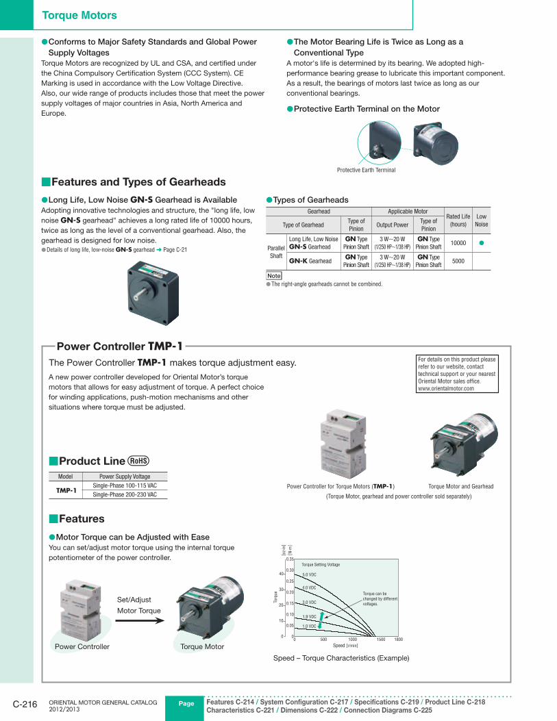
Protective Earth Terminal on the Motor ●
Power Controller TMP-1The Power Controller TMP-1 makes torque adjustment easy.
A new power controller developed for Oriental Motor’s torque
motors that allows for easy adjustment of torque. A perfect choice
for winding applications, push-motion mechanisms and other
situations where torque must be adjusted.
For details on this product please
refer to our website, contact
technical support or your nearest
Oriental Motor sales office.
www.orientalmotor.com
Power Controller for Torque Motors (TMP-1) Torque Motor and Gearhead
(Torque Motor, gearhead and power controller sold separately)
Features ■
Motor Torque can be Adjusted with Ease ●You can set/adjust motor torque using the internal torque
potentiometer of the power controller.
Torque MotorPower Controller
Speed – Torque Characteristics (Example)
Set/Adjust
Motor Torque
1000500 18001500
[ oz-
in]
Torq
ue
[ N·m
]
Speed [r/min]
0
0.30
0.35
0.25
0.20
0.15
0.05
0
10
20
30
40
0
0.10
Torque Setting Voltage
5.0 VDC
4.0 VDC
3.0 VDC
1.9 VDC
1.0 VDC
Torque can be
changed by different
voltages.
Product Line ■
Model Power Supply Voltage
TMP-1Single-Phase 100-115 VAC
Single-Phase 200-230 VAC
Protective Earth Terminal
CAD DataManuals
www.orientalmotor.com Technical Support
TEL: (800) 468-3982E-mail: [email protected]
Standard AC MotorsIn
trod
uctio
nIn
du
ctio
nM
oto
rsR
evers
ible
M
oto
rsE
lectrom
agn
etic B
rake Mo
tors
V S
erie
sC
lutc
h &
B
rake M
oto
rsS
yn
ch
ron
ou
s
Mo
tors
Lo
w-S
peed
S
yn
ch
ron
ou
s
Mo
tors
Wate
rtigh
t, D
ust-R
esis
tan
t M
oto
rs
To
rqu
e
Mo
tors
Rig
ht-A
ng
leG
earh
ead
sL
inear H
ea
ds
Bra
ke
Pack
Accesso
ries
Insta
llatio
n
C-217
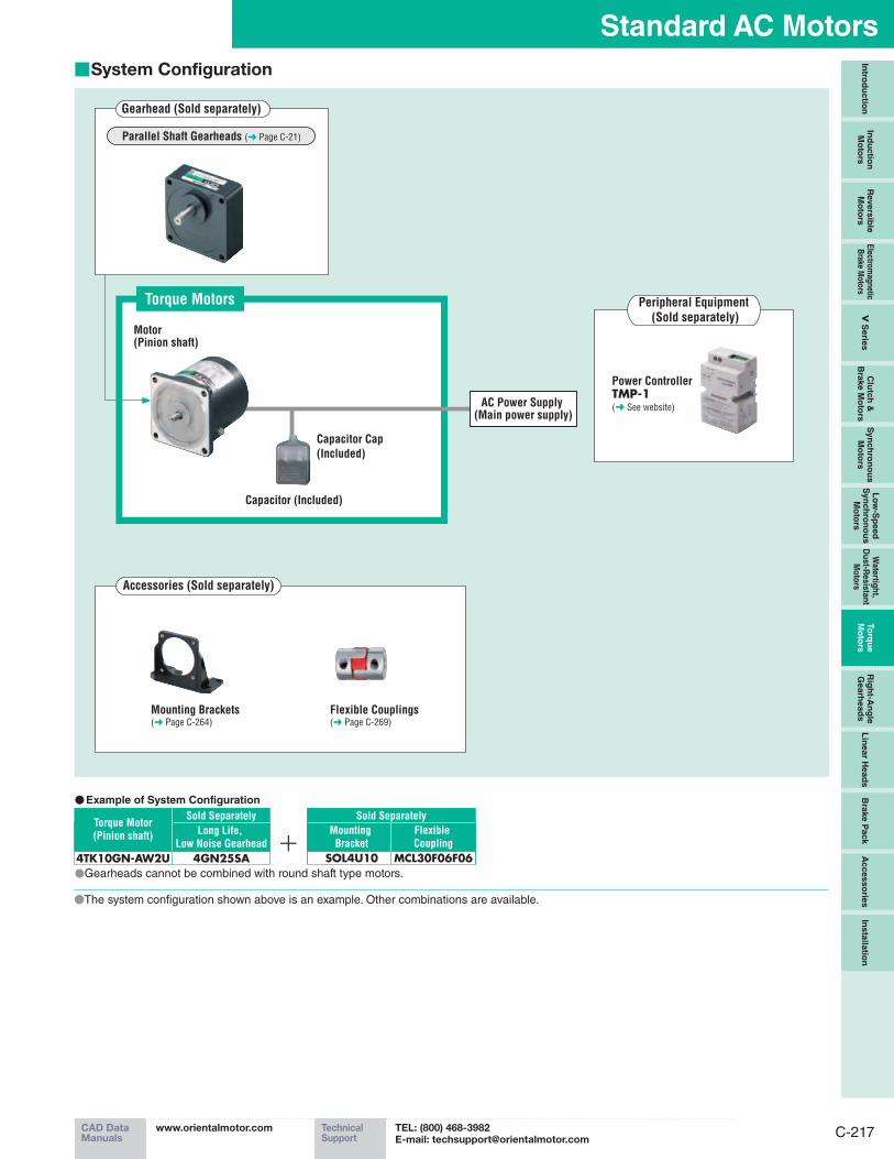
System Configuration ■
Torque Motors
Accessories (Sold separately)
Gearhead (Sold separately)
● Example of System Configuration
Motor(Pinion shaft)
Mounting Brackets (➜ Page C-264)
Flexible Couplings (➜ Page C-269)
SOL4U10
Long Life,
Low Noise Gearhead
4GN25SA
Torque Motor
(Pinion shaft)
4TK10GN-AW2U●Gearheads cannot be combined with round shaft type motors.
Capacitor Cap
(Included)
MCL30F06F06
Parallel Shaft Gearheads (➜ Page C-21)
Capacitor (Included)
AC Power Supply (Main power supply)
Mounting
Bracket
Flexible
Coupling
Sold SeparatelySold Separately
Peripheral Equipment
(Sold separately)
Power ControllerTMP-1(➜ See website)
●The system confi guration shown above is an example. Other combinations are available.
PageORIENTAL MOTOR GENERAL CATALOG 2012/2013
Features C-214 / System Configuration C-217 / Specifications C-219 / Product Line C-218Characteristics C-221 / Dimensions C-222 / Connection Diagrams C-225
C-218
Torque Motors
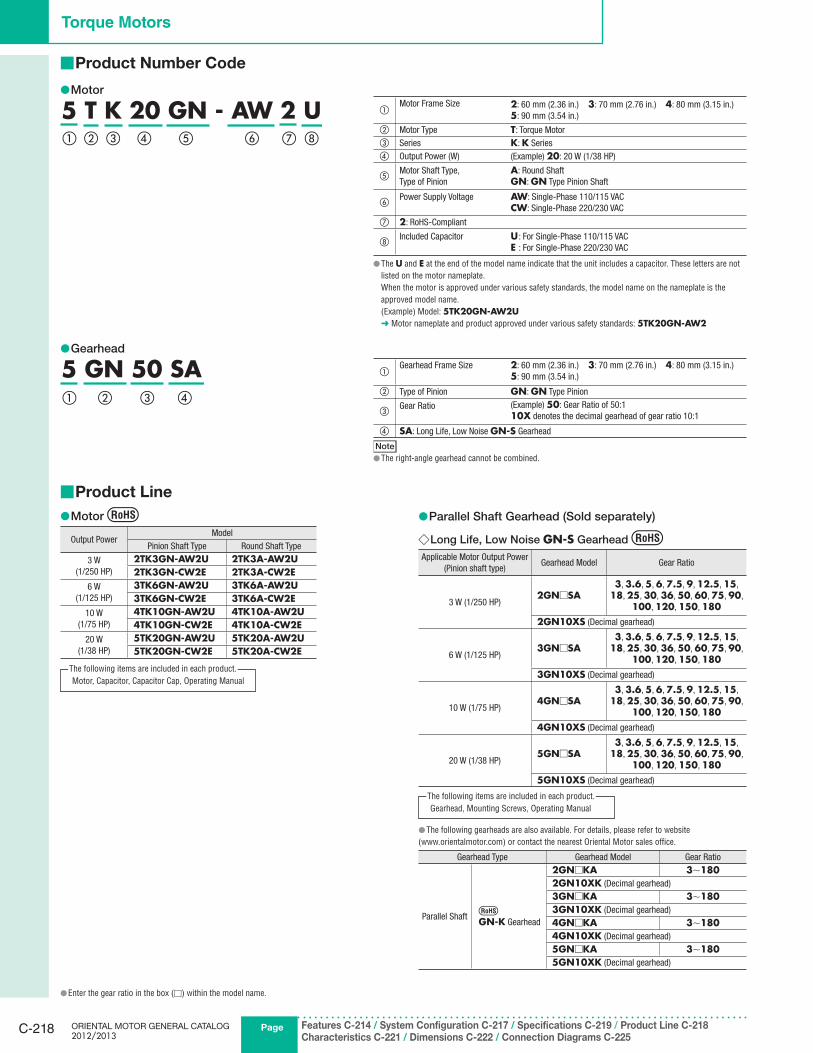
Product Number Code ■
Motor ●
5 T K 20 GN - AW 2 U① ⑦② ⑧③ ④ ⑤ ⑥
Gearhead ●
5 GN 50 SA① ② ③ ④
Product Line ■
Motor ●
Output PowerModel
Pinion Shaft Type Round Shaft Type
3 W
(1/250 HP)
2TK3GN-AW2U 2TK3A-AW2U2TK3GN-CW2E 2TK3A-CW2E
6 W
(1/125 HP)
3TK6GN-AW2U 3TK6A-AW2U3TK6GN-CW2E 3TK6A-CW2E
10 W
(1/75 HP)
4TK10GN-AW2U 4TK10A-AW2U4TK10GN-CW2E 4TK10A-CW2E
20 W
(1/38 HP)
5TK20GN-AW2U 5TK20A-AW2U5TK20GN-CW2E 5TK20A-CW2E
Parallel Shaft Gearhead (Sold separately) ●
Long Life, Low Noise ◇ GN-S Gearhead
Applicable Motor Output Power
(Pinion shaft type)Gearhead Model Gear Ratio
3 W (1/250 HP)2GN□SA
3, 3.6, 5, 6, 7.5, 9, 12.5, 15,
18, 25, 30, 36, 50, 60, 75, 90,
100, 120, 150, 1802GN10XS (Decimal gearhead)
6 W (1/125 HP)3GN□SA
3, 3.6, 5, 6, 7.5, 9, 12.5, 15,
18, 25, 30, 36, 50, 60, 75, 90,
100, 120, 150, 1803GN10XS (Decimal gearhead)
10 W (1/75 HP)4GN□SA
3, 3.6, 5, 6, 7.5, 9, 12.5, 15,
18, 25, 30, 36, 50, 60, 75, 90,
100, 120, 150, 1804GN10XS (Decimal gearhead)
20 W (1/38 HP)5GN□SA
3, 3.6, 5, 6, 7.5, 9, 12.5, 15,
18, 25, 30, 36, 50, 60, 75, 90,
100, 120, 150, 1805GN10XS (Decimal gearhead)
The following gearheads are also available. For details, please refer to website ●(www.orientalmotor.com) or contact the nearest Oriental Motor sales office.
Gearhead Type Gearhead Model Gear Ratio
Parallel Shaft GN-K Gearhead
2GN□KA 3∼1802GN10XK (Decimal gearhead)
3GN□KA 3∼1803GN10XK (Decimal gearhead)
4GN□KA 3∼1804GN10XK (Decimal gearhead)
5GN□KA 3∼1805GN10XK (Decimal gearhead)
①Motor Frame Size 2: 60 mm (2.36 in.) 3: 70 mm (2.76 in.) 4: 80 mm (3.15 in.)
5: 90 mm (3.54 in.)
② Motor Type T: Torque Motor
③ Series K: K Series
④ Output Power (W) (Example) 20: 20 W (1/38 HP)
⑤Motor Shaft Type,
Type of Pinion
A: Round Shaft
GN: GN Type Pinion Shaft
⑥Power Supply Voltage AW: Single-Phase 110/115 VAC
CW: Single-Phase 220/230 VAC
⑦ 2: RoHS-Compliant
⑧Included Capacitor U : For Single-Phase 110/115 VAC
E : For Single-Phase 220/230 VAC
The ● U and E at the end of the model name indicate that the unit includes a capacitor. These letters are not
listed on the motor nameplate.
When the motor is approved under various safety standards, the model name on the nameplate is the
approved model name.
(Example) Model: 5TK20GN-AW2U➜ Motor nameplate and product approved under various safety standards: 5TK20GN-AW2
①Gearhead Frame Size 2: 60 mm (2.36 in.) 3: 70 mm (2.76 in.) 4: 80 mm (3.15 in.)
5: 90 mm (3.54 in.)
② Type of Pinion GN: GN Type Pinion
③Gear Ratio (Example) 50: Gear Ratio of 50:1
10X denotes the decimal gearhead of gear ratio 10:1
④ SA: Long Life, Low Noise GN-S Gearhead
Note
The right-angle gearhead cannot be combined. ●
Enter the gear ratio in the box ( ● □) within the model name.
Motor, Capacitor, Capacitor Cap, Operating Manual
The following items are included in each product.
Gearhead, Mounting Screws, Operating Manual
The following items are included in each product.
CAD DataManuals
www.orientalmotor.com Technical Support
TEL: (800) 468-3982E-mail: [email protected]
Standard AC MotorsIn
trod
uctio
nIn
du
ctio
nM
oto
rsR
evers
ible
M
oto
rsE
lectrom
agn
etic B
rake Mo
tors
V S
erie
sC
lutc
h &
B
rake M
oto
rsS
yn
ch
ron
ou
s
Mo
tors
Lo
w-S
peed
S
yn
ch
ron
ou
s
Mo
tors
Wate
rtigh
t, D
ust-R
esis
tan
t M
oto
rs
To
rqu
e
Mo
tors
Rig
ht-A
ng
leG
earh
ead
sL
inear H
ea
ds
Bra
ke
Pack
Accesso
ries
Insta
llatio
n
C-219
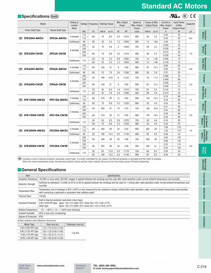
Specifications ■
ModelRating at
Locked
Rotor
Voltage Frequency Starting TorqueMax. Output
Power
Speed at
Max. Output
Power
r/min
Torque at Max.
Output Power
Current at
Max. Output
Power
A
Input Power
at Max.
Output Power
W
Capacitor
Pinion Shaft Type Round Shaft TypeVAC Hz mN·m oz-in W HP mN·m oz-in μF
2TK3GN-AW2U 2TK3A-AW2U5 minutes
11060 70 9.9 3.5 1/210 900 38 5.3
0.42 45
6.0115 0.45 50
Continuous 60 60 25 3.5 1.2 1/620 900 13 1.84 0.26 15
2TK3GN-CW2E 2TK3A-CW2E5 minutes
22050 70 9.9 3 1/250 750 39 5.5
0.220 45
1.5
230 0.240 50
22060 70 9.9 3.5 1/210 900 38 5.3
0.215 45
230 0.230 50
Continuous 11550 18 2.5 0.8 1/930 750 10 1.42 0.095 10
60 25 3.5 1.2 1/620 900 13 1.84 0.130 14
3TK6GN-AW2U 3TK6A-AW2U5 minutes
11060 150 21 8 1/93 900 87 12.3
0.60 65
9.0115 0.65 70
Continuous 60 60 55 7.8 2.6 1/290 900 28 3.9 0.37 20
3TK6GN-CW2E 3TK6A-CW2E5 minutes
22050 140 19.8 6 1/125 750 78 11.0
0.390 70
2.5
230 0.440 80
22060 150 21 8 1/93 900 87 12.3
0.320 70
230 0.350 75
Continuous 11550 45 6.3 1.8 1/410 750 24 3.4 0.145 15
60 55 7.8 2.6 1/290 900 28 3.9 0.210 24
4TK10GN-AW2U 4TK10A-AW2U5 minutes
11060 210 29 12 1/62 900 130 18.4
0.74 80
11115 0.76 85
Continuous 60 60 70 9.9 3.3 1/230 900 35 4.9 0.45 25
4TK10GN-CW2E 4TK10A-CW2E5 minutes
22050 220 31 10 1/75 750 130 18.4
0.41 80
3.0
230 0.45 90
22060 210 29 12 1/62 900 130 18.4
0.39 80
230 0.40 80
Continuous 11550 65 9.2 2.8 1/270 750 35 4.9 0.18 20
60 70 9.9 3.3 1/230 900 35 4.9 0.24 25
5TK20GN-AW2U 5TK20A-AW2U5 minutes
11060 350 49 23 1/32 900 250 35
1.00 110
14115 1.02 115
Continuous 60 60 100 14.2 5.5 1/140 900 60 8.5 0.58 34
5TK20GN-CW2E 5TK20A-CW2E5 minutes
22050 350 49 20 1/38 750 260 36
0.63 120
4.0
230 0.68 130
22060 350 49 20 1/38 900 220 31
0.53 115
230 0.54 120
Continuous 11550 85 12.0 4.5 1/170 750 60 8.5 0.26 29
60 100 14.2 5.5 1/140 900 60 8.5 0.30 34
: Contains a built-in thermal protector (automatic return type). If a motor overheats for any reason, the thermal protector is activated and the motor is stopped.When the motor temperature drops, the thermal protector closes and the motor restarts. Be sure to turn the motor power off before inspecting.
General Specifications ■
Item Specifications
Insulation Resistance 100 MΩ or more when 500 VDC megger is applied between the windings and the case after rated operation under normal ambient temperature and humidity.
Dielectric StrengthSufficient to withstand 1.5 kVAC at 50 Hz or 60 Hz applied between the windings and the case for 1 minute after rated operation under normal ambient temperature and
humidity.
Temperature RiseTemperature rise of windings is 80˚C (144˚F) or less measured by the resistance change method after rated operation under normal ambient temperature and humidity
with connecting a gearhead or equivalent heat radiation plate✽.
Thermal Class 130 (B)
Overheat Protection
Built-in thermal protector (automatic return type)
3 W (1/250 HP) type Open: 130±5˚C (266±9˚F), Close: 90±15˚C (194±27˚F)
Other type Open: 130±5˚C (266±9˚F), Close: 82±15˚C (179.6±27˚F)
Ambient Temperature −10∼+40˚C (+14∼+104˚F) (non-freezing)
Ambient Humidity 85% or less (non-condensing)
Degree of Protection IP20
Heat radiation plate (Material: Aluminum) ✽
Motor Type Size: mm (in.) Thickness: mm (in.)
3 W (1/250 HP) Type 115×115 (4.53×4.53)
5 (0.20)6 W (1/125 HP) Type 125×125 (4.92×4.92)
10 W (1/75 HP) Type 135×135 (5.31×5.31)
20 W (1/38 HP) Type 165×165 (6.50×6.50)
PageORIENTAL MOTOR GENERAL CATALOG 2012/2013
Features C-214 / System Configuration C-217 / Specifications C-219 / Product Line C-218Characteristics C-221 / Dimensions C-222 / Connection Diagrams C-225
C-220
Torque Motors
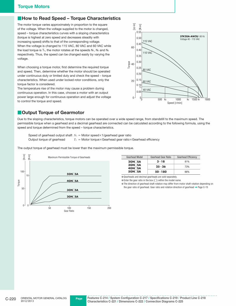
Output Torque of Gearmotor ■
Due to the sloping characteristics, torque motors can be operated over a wide speed range, from standstill to the maximum speed. The
permissible torque when a gearhead and a decimal gearhead are connected can be calculated according to the following formula, using the
speed and torque determined from the speed – torque characteristics.
Speed of gearhead output shaft NG = Motor speed×1/gearhead gear ratio
Output torque of gearhead TG = Motor torque×Gearhead gear ratio×Gearhead efficiency
The output torque of gearhead must be lower than the maximum permissible torque.
The motor torque varies approximately in proportion to the square
of the voltage. When the voltage supplied to the motor is changed,
speed – torque characteristics curves with a sloping characteristics
(torque is highest at zero speed and decreases steadily with
increasing speed) shifts to that of the corresponding voltage.
When the voltage is changed to 115 VAC, 80 VAC and 60 VAC while
the load torque is T0, the motor rotates at the speeds N1, N2 and N3
respectively. Thus, the speed can be changed easily by varying the
voltage.
When choosing a torque motor, first determine the required torque
and speed. Then, determine whether the motor should be operated
under continuous duty or limited duty and check the speed – torque
characteristics. When used under locked rotor conditions, only the
torque factor is considered.
The temperature rise of the motor may cause a problem during
continuous operation. In this case, choose a motor with an output
power large enough for continuous operation and adjust the voltage
to control the torque and speed.0 1000500 18001500
0
0.55
0.40
0.45
0.50
0.30
0.35
0.10
0.15
0.05
0.20
0.25
Speed [r/min]
0
20
40
60
Torq
ue
[N·m
]
[oz-
in]
T0
N3 N2 N1
115 VAC
110 VAC
40 VAC
80 VAC
60 VAC
5TK20A-AW2U 60 Hz
Voltage 40 - 115 VAC
50 100 150 200
10
Gear Ratio
Maximum Permissible Torque of Gearheads
0
5GN□SA
4GN□SA
3GN□SA
2GN□SA
Torq
ue
100
50
0
[N·m
]
[lb-i
n]
Gearhead Model Gearhead Gear Ratio Gearhead Efficiency
2GN□SA3GN□SA4GN□SA5GN□SA
3∼18 81%
25∼36 73%
50∼180 66%
Gearheads and decimal gearheads are sold separately. ●Enter the gear ratio in the box ( ● □) within the model name.
The direction of gearhead shaft rotation may differ from motor shaft rotation depending on ●the gear ratio of gearhead. Gear ratio and rotation direction of gearhead ➜ Page C-15
How to Read Speed – Torque Characteristics ■
CAD DataManuals
www.orientalmotor.com Technical Support
TEL: (800) 468-3982E-mail: [email protected]
Standard AC MotorsIn
trod
uctio
nIn
du
ctio
nM
oto
rsR
evers
ible
M
oto
rsE
lectrom
agn
etic B
rake Mo
tors
V S
erie
sC
lutc
h &
B
rake M
oto
rsS
yn
ch
ron
ou
s
Mo
tors
Lo
w-S
peed
S
yn
ch
ron
ou
s
Mo
tors
Wate
rtigh
t, D
ust-R
esis
tan
t M
oto
rs
To
rqu
e
Mo
tors
Rig
ht-A
ng
leG
earh
ead
sL
inear H
ea
ds
Bra
ke
Pack
Accesso
ries
Insta
llatio
n
C-221
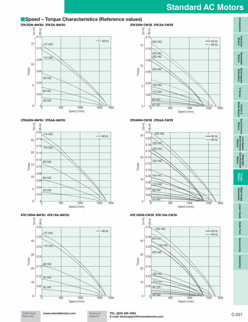
Speed – Torque Characteristics (Reference values) ■
3TK6GN-AW2U, 3TK6A-AW2U
0 1000500 180015000
0.20
0.16
0.18
0.12
0.14
0.04
0.06
0.02
0.08
0.10
Speed [r/min]
0
5
10
25
15
Torq
ue
[N·m
]
[oz-
in]
20
60 Hz
110 VAC
115 VAC
80 VAC
60 VAC
40 VAC
3TK6GN-CW2E, 3TK6A-CW2E
0 1000500 180015000
0.22
0.16
0.18
0.20
0.12
0.14
0.04
0.06
0.02
0.08
0.10
Speed [r/min]
0
10
20
30Torq
ue
[N·m
]
[oz-
in]
50 Hz
60 Hz
230 VAC
230 VAC
115 VAC
80 VAC
220 VAC
60 VAC
140 VAC
220 VAC
4TK10GN-AW2U, 4TK10A-AW2U
0 1000500 180015000
0.35
0.30
0.25
0.10
0.05
0.20
0.15
Speed [r/min]
0
20
10
30
40
Torq
ue
[N·m
]
[oz-
in]
60 Hz115 VAC
80 VAC
60 VAC
110 VAC
40 VAC
4TK10GN-CW2E, 4TK10A-CW2E
0 1000500 180015000
0.35
0.30
0.25
0.10
0.05
0.20
0.15
Speed [r/min]
[N·m
]
0
20
10
30
40
Torq
ue
[oz-
in]
50 Hz
60 Hz
230 VAC
220 VAC
60 VAC
80 VAC
115 VAC
140 VAC
220 VAC
230 VAC
2TK3GN-AW2U, 2TK3A-AW2U
0 1000500 180015000
0.12
0.10
0.08
0.06
0.02
0.04
Speed [r/min]
60 Hz
110 VAC
80 VAC
60 VAC
115 VAC
40 VAC
0
5
10
15
Torq
ue
[N·m
]
[oz-
in]
2TK3GN-CW2E, 2TK3A-CW2E
0 1000500 180015000
0.12
0.10
0.08
0.06
0.02
0.04
Speed [r/min]
0
5
10
15
Torq
ue
[N·m
]
[oz-
in]
50 Hz
60 Hz
220 VAC
220 VAC
230 VAC
230 VAC
140 VAC
115 VAC
80 VAC
60 VAC
PageORIENTAL MOTOR GENERAL CATALOG 2012/2013
Features C-214 / System Configuration C-217 / Specifications C-219 / Product Line C-218Characteristics C-221 / Dimensions C-222 / Connection Diagrams C-225
C-222
Torque Motors
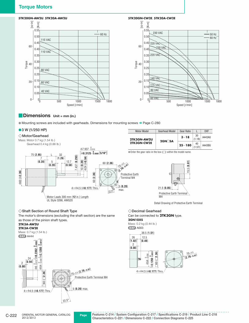
5TK20GN-AW2U, 5TK20A-AW2U
0 1000500 180015000
0.55
0.40
0.45
0.50
0.30
0.35
0.10
0.15
0.05
0.20
0.25
Speed [r/min]
0
20
40
60
Torq
ue
[N·m
]
[oz-
in]
60 Hz
115 VAC
110 VAC
40 VAC
80 VAC
60 VAC
5TK20GN-CW2E, 5TK20A-CW2E
0 1000500 180015000
0.55
0.40
0.45
0.50
0.30
0.35
0.10
0.15
0.05
0.20
0.25
Speed [r/min]
0
20
40
60
Torq
ue
[N·m
]
[oz-
in]
50 Hz
60 Hz
230 VAC
80 VAC
60 VAC
220 VAC
230 VAC
220 VAC
115 VAC
140 VAC
Dimensions ■ Unit = mm (in.)
Mounting screws are included with gearheads. Dimensions for mounting screws ● ➜ Page C-280
3 W (1/250 HP) ●Motor/Gearhead ◇
Mass: Motor 0.7 kg (1.54 lb.) Gearhead 0.4 kg (0.88 lb.)
60 (2.36)
22.5°
5 (0.20)
max.
70±0.5
(2.76±
0.02)
7.4
37
( 0.2
93)
ϕ24
(ϕ0.9
4)
10
( 0.3
9)
32(1.26)
L75 (2.95)
5(0.20)
7(0.28)
ϕ60
(ϕ2.3
6)
60
( 2.3
6)
12.7(0.50)
Motor Leads 300 mm (12 in.) Length
UL Style 3266, AWG20
ϕ7.937−0.015
ϕ0.3125−0.0006 (5/16")
0
0
4×ϕ4.5 (ϕ0.177) Thru
Protective Earth
Terminal M4
Motor Model Gearhead Model Gear Ratio L DXF
2TK3GN-AW2U2TK3GN-CW2E 2GN□SA
3∼18 30
(1.18)A443AU
25∼180 40
(1.57)A443BU
Enter the gear ratio in the box ( ● □) within the model name.
15.5
( 0.6
1)
21.5 (0.85)
Detail Drawing of Protective Earth Terminal
Protective Earth TerminalM4
Shaft Section of Round Shaft Type ◇The motor’s dimensions (excluding the shaft section) are the same
as those of the pinion shaft types.
2TK3A-AW2U2TK3A-CW2EMass: 0.7 kg (1.54 lb.)
A444
2(0.08)
24(0.94)
22.5°
70±0.5 (2.76±0.02)
□60
( □2.3
6)
Protective Earth Terminal M4
5 (0.20) max.4×ϕ4.5 (ϕ0.177) Thru
ϕ6−
0.0
12
( ϕ0.2
362−
0.0
00
5)
00
ϕ54−
0.0
30
( ϕ2.1
260−
0.0
01
2)
00
Decimal Gearhead ◇Can be connected to 2TK3GN type.
2GN10XSMass: 0.2 kg (0.44 lb.)
A003
38.5 (1.51)
26(1.02)
12.5(0.49)
2(0.08)
70±0.5
(2.76±0.02)
□60
( □2.3
6)
4×ϕ4.5 (ϕ0.177) Thru
( ϕ2.
1260
−0.
0012
)ϕ
54−
0.0
30
0
0
CAD DataManuals
www.orientalmotor.com Technical Support
TEL: (800) 468-3982E-mail: [email protected]
Standard AC MotorsIn
trod
uctio
nIn
du
ctio
nM
oto
rsR
evers
ible
M
oto
rsE
lectrom
agn
etic B
rake Mo
tors
V S
erie
sC
lutc
h &
B
rake M
oto
rsS
yn
ch
ron
ou
s
Mo
tors
Lo
w-S
peed
S
yn
ch
ron
ou
s
Mo
tors
Wate
rtigh
t, D
ust-R
esis
tan
t M
oto
rs
To
rqu
e
Mo
tors
Rig
ht-A
ng
leG
earh
ead
sL
inea
r Head
sB
rake P
ack
Accesso
ries
Insta
llatio
n
C-223
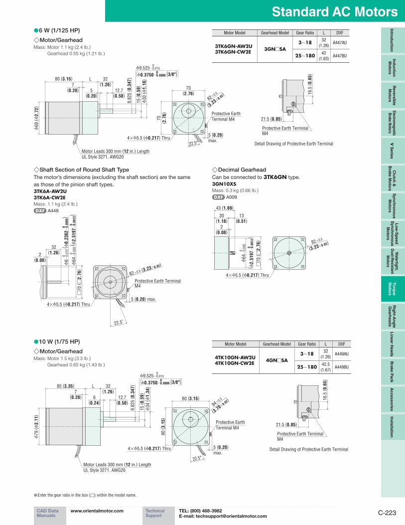
6 W (1/125 HP) ●Motor/Gearhead ◇
Mass: Motor 1.1 kg (2.4 lb.) Gearhead 0.55 kg (1.21 lb.)
5 (0.20)
max.
8.8
25
( 0.3
47)32
(1.26)L80 (3.15)
ϕ69
(ϕ2.7
2)
7(0.28) 5
(0.20)12.7
(0.50)
70(2.76)
ϕ30
(ϕ1.1
8)
15
( 0.5
9)
ϕ9.525−0.015
ϕ0.3750−0.0006 (3/8")
0
0
22.5°
Motor Leads 300 mm (12 in.) Length
UL Style 3271, AWG20
82±0.5
(3.23±
0.02)
4×ϕ5.5 (ϕ0.217) Thru
70
( 2.7
6) Protective Earth
Terminal M4
Motor Model Gearhead Model Gear Ratio L DXF
3TK6GN-AW2U3TK6GN-CW2E 3GN□SA
3∼18 32
(1.26)A447AU
25∼180 42
(1.65)A447BU
16.5
( 0.6
5)
21.5 (0.85)
Detail Drawing of Protective Earth Terminal
Protective Earth TerminalM4
Shaft Section of Round Shaft Type ◇The motor’s dimensions (excluding the shaft section) are the same
as those of the pinion shaft types.
3TK6A-AW2U3TK6A-CW2EMass: 1.1 kg (2.4 lb.)
A448
2(0.08)
32(1.26)
82±0.5 (3.23±0.02)
□70
( □2.7
6)
22.5˚
5 (0.20) max.
Protective Earth TerminalM4
4×ϕ5.5 (ϕ0.217) Thru
ϕ6−
0.0
12
( ϕ0.2
362−
0.0
00
5)
00
ϕ64−
0.0
30
( ϕ2.5
197−
0.0
01
2)
00
Decimal Gearhead ◇Can be connected to 3TK6GN type.
3GN10XSMass: 0.3 kg (0.66 lb.)
A009
43 (1.69)
30(1.18)
13(0.51)
2(0.08)
82±0.5
(3.23±0.02)
□70
( □2.7
6)
4×ϕ5.5 (ϕ0.217) Thru
( ϕ2.5
197−
0.0
01
2)
0
ϕ64−
0.0
30
0
10 W (1/75 HP) ●Motor/Gearhead ◇
Mass: Motor 1.5 kg (3.3 lb.) Gearhead 0.65 kg (1.43 lb.)
8.8
25
( 0.3
47)32
(1.26)
15
( 0.5
9)
ϕ34
(ϕ1.3
4)
12.7(0.50)
L85 (3.35)
ϕ79
(ϕ3.1
1)
7(0.28) 6
(0.24)80 (3.15)
5 (0.20)
max.
22.5°
94±0.5
(3.70±
0.02)
80
( 3.1
5)
ϕ9.525−0.015
ϕ0.3750−0.0006 (3/8")
0
0
Motor Leads 300 mm (12 in.) Length
UL Style 3271, AWG20
4×ϕ5.5 (ϕ0.217) Thru
Protective Earth
Terminal M4
Motor Model Gearhead Model Gear Ratio L DXF
4TK10GN-AW2U4TK10GN-CW2E 4GN□SA
3∼18 32
(1.26)A449AU
25∼180 42.5
(1.67)A449BU
16.5
( 0.6
5)
21.5 (0.85)
Detail Drawing of Protective Earth Terminal
Protective Earth TerminalM4
Enter the gear ratio in the box ( ● □) within the model name.
PageORIENTAL MOTOR GENERAL CATALOG 2012/2013
Features C-214 / System Configuration C-217 / Specifications C-219 / Product Line C-218Characteristics C-221 / Dimensions C-222 / Connection Diagrams C-225
C-224
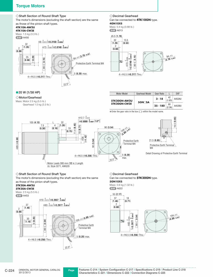
Torque Motors
20 W (1/38 HP) ●Motor/Gearhead ◇
Mass: Motor 2.5 kg (5.5 lb.) Gearhead 1.5 kg (3.3 lb.)
11.4
( 0.4
5)
18
( 0.7
1)
ϕ36
(ϕ1.4
2)
32(1.26)4
(0.16) 19(0.75)
L105 (4.13)
ϕ89
(ϕ3.5
0)
90 (3.54)
90
( 3.5
4)
5 (0.20)
max.22.5°
7.5(0.30)
104±0.5
(4.09±
0.02)
Motor Leads 300 mm (12 in.) Length
UL Style 3271, AWG20
4×ϕ6.5 (ϕ0.256) Thru
ϕ12.7−0.018
ϕ0.5000−0.0007 (1/2")
0
0
Protective Earth
Terminal M4
Motor Model Gearhead Model Gear Ratio L DXF
5TK20GN-AW2U5TK20GN-CW2E 5GN□SA
3∼18 42
(1.65)A452AU
25∼180 60
(2.36)A452BU
Enter the gear ratio in the box ( ● □) within the model name.
16.5
( 0.6
5)
21.5 (0.85)
Detail Drawing of Protective Earth Terminal
Protective Earth TerminalM4
Shaft Section of Round Shaft Type ◇The motor’s dimensions (excluding the shaft section) are the same
as those of the pinion shaft types.
4TK10A-AW2U4TK10A-CW2EMass: 1.5 kg (3.3 lb.)
A450
2(0.08)
32(1.26)
94±0.5 (3.70±0.02)
25(0.98)
7( 0
.28)
□80
( □3.1
5)
22.5°
5 (0.20) max.
Protective Earth Terminal M4
4×ϕ5.5 (ϕ0.217) Thru
ϕ8−0.015 (ϕ0.3150−0.0006)00
ϕ73−0.030 (ϕ2.8740−0.0012)00
Decimal Gearhead ◇Can be connected to 4TK10GN type.
4GN10XSMass: 0.4 kg (0.88 lb.)
A013
45.5 (1.79)
32(1.26)
13.5(0.53)
2(0.08)
□80
( □3.1
5)
94±0.5
(3.70±0.02)
4×ϕ5.5 (ϕ0.217) Thru
ϕ73−
0.0
30
( ϕ2.8
740−
0.0
01
2)
0
0
Shaft Section of Round Shaft Type ◇The motor’s dimensions (excluding the shaft section) are the same
as those of the pinion shaft types.
5TK20A-AW2U5TK20A-CW2EMass: 2.5 kg (5.5 lb.)
A453
2(0.08)
37(1.46)
30(1.18)
9( 0
.35)
104±0.5 (4.09±0.02)
□90
( □3.5
4)
22.5°
5 (0.20) max.
Protective Earth Terminal M4
4×ϕ6.5 (ϕ0.256) Thru
ϕ10−0.015 (ϕ0.3937−0.0006)00
ϕ83−0.035 (ϕ3.2677−0.0014)00
Decimal Gearhead ◇Can be connected to 5TK20GN type.
5GN10XSMass: 0.6 kg (1.32 lb.)
A022
37(1.46)
18(0.71)
55 (2.17)
2(0.08)
□90
( □3.5
4)
104±0.5
(4.09±0.02)
4×ϕ6.5 (ϕ0.256) Thru
ϕ83−
0.0
35
( ϕ3.2
677−
0.0
01
4)
0
0
CAD DataManuals
www.orientalmotor.com Technical Support
TEL: (800) 468-3982E-mail: [email protected]
Standard AC MotorsIn
trod
uctio
nIn
du
ctio
nM
oto
rsR
evers
ible
M
oto
rsE
lectrom
agn
etic B
rake Mo
tors
V S
erie
sC
lutc
h &
B
rake M
oto
rsS
yn
ch
ron
ou
s
Mo
tors
Lo
w-S
peed
S
yn
ch
ron
ou
s
Mo
tors
Wate
rtigh
t, D
ust-R
esis
tan
t M
oto
rs
To
rqu
e
Mo
tors
Rig
ht-A
ng
leG
earh
ead
sL
inea
r Head
sB
rake P
ack
Accesso
ries
Insta
llatio
n
C-225
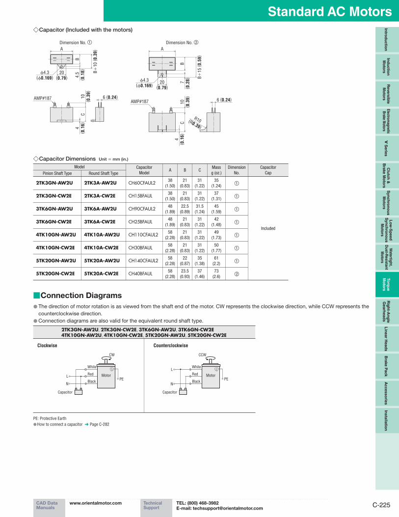
Capacitor (Included with the motors) ◇
Dimension No. ① Dimension No. ②
ϕ4.3(ϕ0.169)
20(0.79)
A
C
B+
10
( 0.3
9)
B4.5
( 0.1
8)
4( 0
.16)
10
( 0.3
9)
6 (0.24)AMP#187 6 (0.24)
A
CB
7( 0
.28)
20(0.79)
10
( 0.3
9)
AMP#187
ϕ4.3(ϕ0.169)
4( 0
.16)
B+
15
( 0.5
9)
R10(R0.39)
Capacitor Dimensions ◇ Unit = mm (in.)
Model Capacitor
ModelA B C
Mass
g (oz.)
Dimension
No.
Capacitor
CapPinion Shaft Type Round Shaft Type
2TK3GN-AW2U 2TK3A-AW2U CH60CFAUL2 38
(1.50)
21
(0.83)
31
(1.22)
35
(1.24)①
Included
2TK3GN-CW2E 2TK3A-CW2E CH15BFAUL 38
(1.50)
21
(0.83)
31
(1.22)
37
(1.31)①
3TK6GN-AW2U 3TK6A-AW2U CH90CFAUL2 48
(1.89)
22.5
(0.89)
31.5
(1.24)
45
(1.59)①
3TK6GN-CW2E 3TK6A-CW2E CH25BFAUL 48
(1.89)
21
(0.83)
31
(1.22)
42
(1.48)①
4TK10GN-AW2U 4TK10A-AW2U CH110CFAUL2 58
(2.28)
21
(0.83)
31
(1.22)
49
(1.73)①
4TK10GN-CW2E 4TK10A-CW2E CH30BFAUL 58
(2.28)
21
(0.83)
31
(1.22)
50
(1.77)①
5TK20GN-AW2U 5TK20A-AW2U CH140CFAUL2 58
(2.28)
22
(0.87)
35
(1.38)
61
(2.2)①
5TK20GN-CW2E 5TK20A-CW2E CH40BFAUL 58
(2.28)
23.5
(0.93)
37
(1.46)
73
(2.6)②
Connection Diagrams ■
The direction of motor rotation is as viewed from the shaft end of the motor. CW represents the clockwise direction, while CCW represents the ●counterclockwise direction.
Connection diagrams are also valid for the equivalent round shaft type. ●
2TK3GN-AW2U, 2TK3GN-CW2E, 3TK6GN-AW2U, 3TK6GN-CW2E4TK10GN-AW2U, 4TK10GN-CW2E, 5TK20GN-AW2U, 5TK20GN-CW2E
Clockwise Counterclockwise
Capacitor
Black
RedL
N
White
Black
Red
White
MotorPE
CW
L
N
MotorPE
Capacitor
CCW
PE: Protective Earth
How to connect a capacitor ● ➜ Page C-282

ORIENTAL MOTOR GENERAL CATALOG 2012/2013
C-226
Torque Motors