series c h y d r a u l i c - m a gnetic circuit breakers · series c h y d r a u l i c - m a gnetic...
TRANSCRIPT

Series CH y d r a u l i c - M agnetic Circuit Breakers Compact E-Frame circuit breaker Single and multipole VDE/UL/CSA recognized UL 489 listed to 10000 A International Approvals Ratings: 0.1 A to 100 A
Heinemann® Circuit Breakers
I S O 9001 Certified

1
C F
C D
HYDRAULIC-MAGNETIC CIRCUIT BREAKERS
DESCRIPTION 2HYDRAULIC -MAGNETIC PRINCIPLE
TECHNICAL SPECIFICATIONS 3
A P P R O V A L S 4
INTERNAL CIRCUITS 5
TIME DELAY CURVE 7
A C C E S S O R I E S 1 1
TYPES OF THE C SERIES 1 2
DIMENSIONS OF CF TYPE 1 3FRONT TERMINALS
DIMENSIONS OF CD TYPE 1 5FRONT TERMINALS
DIMENSIONS OF CD TYPE 1 7BACK TERMINALS
DIMENSIONS AND LOCATION OF CD TYPE 1 9BACK TERMINALS
CD/CF AUXILIARY CONTACT 2 0TORQUE ALLOWED
HOW TO ORDER 2 2
The technical information published in this handbook is subjectto change without prior notice. Modifications may occur as partof continual improvement of our products.
Heinemann is a registered trademark.
S E R I E S C
ContentsT y p e

2
D e s c r i p t i o n
P r i n c i p l e
HYDRAULIC-MAGNETIC PRINCIPLE
1 The handle has two positions only «ON» and «OFF», givingan unmistakable visual indication of the switch position.However, the MID-TRIP versions have three. (See workingprinciple page 12).
2 Tripping of all C hydraulic-magnetic MCB’s is caused byexcess current through the solenoid. This is designed forthe rated currents and is not influenced by the prevailingambient temperature with regard to its operating point.
3 For each make and break operation the moving contactarm slides across the lower contact area, thus creating awiping action which guarantees low contact resistance and,therefore, long life.
4 The armature is completely balanced, thus preventingswitching off under severe shock and vibration conditions.
5 The switch mechanism is simple and robust. Designed «tripfree» so that it is impossible to hold on the switch againstan existing short-circuit.
6 The arc produced by the switch operation is broken downinto a number of smaller arcs by the special shape of thecontacts and the extinguishing grids, and is blown out bythe magnetic field generated. The arc is formed on specialcontact surfaces
7 C MCB’s can also be supplied with auxiliary contacts.
The load current is either at or below the nominal rating of thebreaker - The core remains at the end of the tube opposite tothe armature.
1. tube / 2. c o r e / 3. s p r i n g / 4. fluid / 5. frame / 6. coil (sensor) / 7. pole piece / 8. a r m a t u r e
Moderate overload - The core is moving.
Overload - The core has fully moved to the opposite end of thetube (pole piece) attracting the armature - the breaker hast r i p p e d .
On heavy overloads or short circuits, the flux produced by thecoil alone, regardless of core position, is sufficient to pull in thearmature - The breaker trips. This circuit interruption occurs with no intentional delay.
2
3
45
6
7 1
1
4
2
3

3
[ Ω ] INTERNAL RESISTANCE CAT - 12404 - Y4 Rev. A
[ A ] AMPERE RATING
T e m p e r a t u r e - 40°C + 85°C
H u m i d i t y IEC 68-2-3 and MIL - STD - 202Method 103 Test A
P r o t e c t i o n IEC 529IP 00 C D Back terminals sealingIP 00 C D - C F Front terminals sealingIP 40 C D Front sealing
S h o c k IEC 68-2-27MIL - STD - 202, method 213cond 1 100 G, 6 mso r 50 G, 11 ms
V i b r a t i o n IEC 68-2-6MIL - STD - 202, method 20410 to 500 Hz 10 Gamplitude 1,52 mm
L i f e 10 000 switching operationswith 6000 at rated current50/60 Hz
Approx. weights 1 pole 262 g2 poles 564 g3 poles 936 g4 poles 1148 g5 poles 1410 g6 poles 1772 g
A p p r o v a l s UL - CSA and VDEIn conformity with IEC 950
Dielectric strength 3750 V A C 50/60 Hz
Insulation resistance 100 MΩ under 500 V D C
Auxiliary switches 220 V A C : 1 0 ARated current 24 V D C : 8 A (resistive)
220 V A C : 0 , 1 A(contact AgAuPt)
Tolerance limits of internal resistance
C u r r e n t ( A ) T o l e r a n c e s ( % )
0,01 to 29,9 ± 2 5
30 to 100 ± 3 5
Technical characteristics
TECHNICAL SPECIFICATIONS
Resistance and impedance values
400 Hz
AC - DC

4
Approvals V D E - U L - C S A
Safety standardsIEC 950
Figure 1
One-pole circuit breaker withauxiliary contacts. Theinsulation voltage between themain circuits and the safetyvoltage circuit is 3750 V.
D e s c r i p t i o n
1. Circuit breaker withauxiliary contact
2. S i g n a l i n g3. Circuit to be protected
C circuit breakers comply with the international safety standardsrelating to information processing equipment IEC 950. Inparticular, the minimum creep distances (8 mm) between two metal parts of different potential or between the differentelectrical circuits are respected and the insulation voltage is 3750 V.
The circuit breakers equipped with one auxiliary contact(microswitch) enable low-voltage safety circuits to besimultaneously switched with the protection of an apparatusconnected to the mains. (See figures 1 and 2).
CAT - 1402 - Y4 Rev. A
APPROVALS
Figure 2
Two-pole circuit breaker for theprotection of a motor withelectronic remote control.
D e s c r i p t i o n
4 . Two-pole circuit breaker;protection + low-voltagec o n t r o l
5 . Electronic control
CAT - 1502 - Y4 Rev. A
Line Extra low-voltage Line Extra low-voltage
* Rating insulation voltage (Ui): 400 V ACWorking shock strength voltage (Uimp): 8 kV, T1/T2 = 1,2/50 µ sWorking category: A
I n t e r r u p t i n gT y p e N b . Rating operating voltage Rating current c a p a c i t y
p o l e s U e I n Icu = Ics
D I NE N 6 0 9 4 7 - 2 * CD - CF 1 230 V 50/60/400 Hz 0.1 - 100 A 4000 Acertified CENELEC CD - CF 2 - 4 400 V 50/60/400 Hz 0.1 - 100 A 4000 A
CD - CF 1 - 2 125 V D C 0.1 - 100 A 5000 A
UL 1077 CD - CF 1 - 6 240 V 50/60 Hz 1 - 100 A 7500 ACSA C 22.2 CD - CF 1 - 6 240 V 400 Hz 1 - 100 A 5000 A
CD - CF 1 - 6 125 V D C 1 - 100 A 5000 A
UL 508 CD - CF 2, 3, 4, 6 600 V 50/60 Hz 1 - 77 A 5000 (10000) ACSA C 22.2 CD - CF 2, 3, 4, 6 480 V 50/60 Hz 1 - 100 A 5000 (10000) A
CD - CF 1, 2, 3, 4, 6 277 V 50/60 Hz 1 - 100 A 5000 ACD - CF 1, 2, 3, 4, 6 240 V 50/60 Hz 1 - 100 A 5000 ACD - CF 1, 2, 3, 4, 6 240 V 400 Hz 1 - 100 A 2000 ACD - CF 1, 2, 3, 4, 6 125 V D C 1 - 100 A 5000 A
Application généraleUL 489 (LISTED) CD - CF 1 - 3 240 V 50/60 Hz 1 - 100 A 7500 ACSA C 22.2 CD - CF 1 - 3 125 V D C 1 - 100 A 5000 A
Application spécialeUL 489 (LISTED) CD - CF 1 - 3 240 V 50/60 Hz 1 - 100 A 7500 ACSA C 22.2 CD - CF 1 - 3 125 V D C 1 - 100 A 5000 A
230 V AC 24 V AC
3750 V
230 V AC 24 V AC
3750 V

How to order:
5
S w i t c h
Series Trip
Series Trip with auxiliary contact
Shunt Trip
Construction represented: 12
CAT - 1604 - Y4 Rev. A
Construction represented: 3, 8
CAT - 1704 - Y4 Rev. A
Construction represented: 2, 9
CAT - 1804 - Y4 Rev. A
Construction represented: 5, 22
CAT - 1904 - Y4 Rev. A
A u x i l i a r yc o n t a c t C o d e
w i t h o u t 0
1 1 2
The contacts and the coil are inseries. This is the currentexecution of the C circuitb r e a k e r .It is often used as main switchat the same time.
The contacts and the coil are inseries. Auxiliary contacts areplaced behind the circuitbreaker and mechanicallyconnected to the releasings y s t e m .
Enables two loads to bechecked by means of a singlecircuit breaker. However it onlyreleases if there is an overloadin the main circuit. The sum ofthe two nominal currents mustnot exceed the peak current ofthe contacts. With thisexecution it is also possible toadjust the tripping through apotentiometer between theload terminals.
Switch only (without coil) withor without auxiliary contact.
S t a r to v e r c u r r e n t 8 x 1 5 x
2 2 x
C o d e 3 8
S t a r to v e r c u r r e n t 8 x 1 5 x
2 2 x
Aux. contact C o d e
1 2 9
S t a r to v e r c u r r e n t 8 x 1 5 x
2 2 x
C o d e 5 2 2
C o d e sD e s c r i p t i o n s
0
1 2
3
8
2
9
5
2 2
D i a g r a m s
Line (1)
Load (2)
Line (1)
Load (2)
Line (1)
Load (2)
Line (1) B
Shunt (3) D
Load (2) A
4
INTERNAL CIRCUITS
(11) C
(14) NO
(12) NC
(11) C
(14) NO
(12) NC

Relay trip
Dual rating
Dual Control (Ducon)
Dual Control (Ducon) (Series + Relay)
Relay tripping can be used forreleasing the circuit breaker bythe intermediary of a monitoror a safety device installed at adistance. The contacts areelectrically separated from thecoil. Consequently, all thecurrents and voltages withinthe permissible limits can beused. Coils are either current orvoltage sensitive.The circuit breaker can besupplied on request with adielectric strength ranging upto 2500 V on alternatingcurrent 50/60 Hz betweenthe coil and the contacts.
Dual rating circuit breakers aresuitable for apparatusoperating under two differentcurrents or voltages. As far aspossible, the currents must bein the ratio of one to two witha maximum of 25 to 50 A.
This version is used both forthe protection of the loadfinding itself in series with thecircuit breaker and for therelease via a voltage. The maincoil is in series with the contactand the DUCON coil is shuntt r i p .
Same function as codes 15and 25, but both coils are electrically separated.
6
C o d e sD e s c r i p t i o n sD i a g r a m s
S t a r to v e r c u r r e n t 8 x 1 5 x
2 2 x
C o d e 7 2 7
S t a r to v e r c u r r e n t 8 x 1 5 x
2 2 x
C o d e 1 5 2 5
6
2 3
6 2
7
2 7
1 5
2 5
1 6
2 6
6 3
S t a r to v e r c u r r e n t 8 x 1 5 x
2 2 x
Aux. contact C o d e
w i t h o u t 6 2 3
1 6 2 *
* Code 62: with flying leadsDUCON terminals, further information on request.
S t a r to v e r c u r r e n t 8 x 1 5 x
2 2 x
Aux. contact C o d e
w i t h o u t 1 6 2 6
1 6 3 *
* Code 63: with flying leadsDUCON terminals, further information on request.
How to order: 4

50 Hz60 Hz
Tripping specifications
High-inrush rates validfor different curves
Curve P 50/60 Hz, 400 Hz, DC
All curves describe breaker response with no preloading. Curvesare plotted at an ambient temperature of 25° C, with breakersin the standard wall -mount position.
All circuit breakers shall hold 100% rated load continuously.
Breakers for 50/60 Hz or DC service may trip between 101%and 125% rated load, must trip at 125% and above, as shownon the time-delay curve selected. (150% for 400 Hz).
Non-time-delay circuit breakers (P curve) may trip instantaneouslybetween 101 % and 125 % of rated load, must trip instanta-neously at 125 % for 50/60 Hz or DC (150 % for 400 Hz).
The voltage trip breakers may trip below 100% rated voltage,must trip at 100% and above.
They are only available in no-time-delay construction (P curve).
TIME DELAY CURVES
CAT - 2504 - Y4 Rev. A
C circuit breakers are available with various levels of high-inrush currents avoiding nuisance tripduring short starting periodes at turn on.
In case of motor protections for example, causing a steep wave front transient of very highcurrent amplitude and short duration of overload, the breaker does not trip.
By using C high-inrush types, unnecessary and dangerous overcalibrations involving use of thickercables or wires can be avoided, thus saving energy and money.
The magnetic shunt used offers maximum possibilities on half wave which is 10 ms whenfrequency is 50 Hz. At 60 Hz half wave periode is 8 ms based on value of 1800% instead of1500% and 2500% instead of 2200% at 50 Hz.
For high-inrush rates see pages 5 and 6. For curves P, high-inrush is not possible.
Time delay curve codes are based on selection of high-inrushv a l u e s
at 8 x In curves 1 - 2 - 3 at 15 x In c u r v e s 1 0 - 2 0 - 30 at 22 x In c u r v e s 1 0 0
7
I n . % 1 2 5 1 5 0 2 0 0 3 0 0 4 0 0 5 0 0 6 0 0 7 0 0 8 0 0 9 0 0 1 0 0 0 1 1 0 0 1 2 0 0
50/60 Hz/DC M A X . 0 5 0. 0 2 8 . 0 1 7. 0 1 2 . 0 0 9 8 . 0 0 9 . 0 0 8 7. 0 0 8 5 . 0 0 8 5. 0 0 8 5. 0 0 8 5. 0 0 8 5. 0 0 8 5
400 Hz M A X . 0 5 0. 0 2 8 . 0 1 7 . 0 1 2. 0 0 9 8 . 0 0 9 . 0 0 8 7. 0 0 8 5 . 0 0 8 5. 0 0 8 5. 0 0 8 5. 0 0 8 5. 0 0 8 5
Internal circuit concerned
2, 3, 5, 6, 7, 15, 16, 62, 63
CAT - 12604 - Y4 Rev. A
How to order: 1 2
[ s ]
In [%]

CAT - 13004 - Y4 Rev. D
[ s ]
In [%]
CAT - 13104 - Y4 Rev. A
[ s ]
In [%]
CAT - 12904 - Y4 Rev. A
[ s ]
In [%]
8
Curve 1.2.350/60 Hz
Curve 1.2.3D C
Curve 1.2.3400 Hz
TIME DELAY CURVESSTART OVERLOAD 8 x In
INTERNAL CIRCUITS CONCERNED :2, 3, 5, 6, 7, 15, 16, 62, 63
C u r v e I n . % 1 2 5 1 5 0 2 0 0 3 0 0 4 0 0 5 0 0 6 0 0 7 0 0 8 0 0 9 0 0 1 0 0 0 1 1 0 0 1 2 0 0
1 M A X 8 8 0 3 2 5 1 1 0 4 0 1 8 8 4 . 0 3 . 0 0 0 1 . 6 0 . 1 3 0 . 0 4 5 - -MIN 100 48 20 9 4 2 .9 .016 .013 .012 .010 - -
2 M A X 9 0 3 7 1 0 . 5 3 . 4 0 1 . 8 4 1 . 0 0 . 6 4 . 3 8 0 . 1 9 0 . 0 8 0 . 0 4 5 - -M I N 1 3 6 2 . 1 . 8 3 . 4 6 . 2 5 . 0 3 . 0 1 6 . 0 1 3 . 0 1 1 . 0 1 0 - -
3 M A X 6 . 4 0 2 . 2 0 . 6 0 . 2 0 . 1 3 0 . 0 9 6 . 0 7 5 . 0 6 4 . 0 5 2 . 0 4 6 . 0 4 0 - -M I N . 8 0 . 4 0 . 1 5 . 0 5 . 0 3 2 . 0 2 4 . 0 1 9 . 0 1 6 . 0 1 3 . 0 1 2 . 0 1 0 - -
CURVE 1: LONG DELAYCURVE 2: MEDIUM DELAYCURVE 3: SHORT DELAY
C u r v e I n . % 1 2 5 1 5 0 2 0 0 3 0 0 4 0 0 5 0 0 6 0 0 7 0 0 8 0 0 9 0 0 1 0 0 0 1 1 0 0 1 2 0 0
1 M A X 1 0 0 0 3 6 0 1 0 0 3 6 1 6 8 5 . 2 0 3 . 0 0 1 . 7 0 . 8 0 0 . 3 5 0 - -MIN 120 60 22 9 4 2 .11 .02 .01 .009 .008 - -
2 M A X 9 0 3 6 . 0 1 3 . 0 4 . 2 0 2 . 4 0 1 . 5 0 . 8 0 . 5 0 0 . 2 9 . 0 9 5 . 0 5 5 - -M I N 1 2 5 . 9 2 . 5 . 9 5 . 5 0 . 3 0 . 1 9 . 0 1 3 . 0 1 . 0 0 9 . 0 0 8 - -
3 M A X 8 . 0 0 1 . 9 0 . 6 5 . 2 6 0 . 1 5 0 . 1 0 0 . 7 5 . 0 6 5 . 0 4 7 . 0 4 5 . 0 3 8 - -M I N . 4 4 . 2 5 . 1 3 . 0 5 2 . 0 3 0 . 0 2 0 . 0 1 5 . 0 1 2 . 0 1 0 . 0 0 9 . 0 0 8 - -
CURVE 1: LONG DELAYCURVE 2: MEDIUM DELAYCURVE 3: SHORT DELAY
C u r v e I n . % 1 2 5 1 5 0 2 0 0 3 0 0 4 0 0 5 0 0 6 0 0 7 0 0 8 0 0 9 0 0 1 0 0 0 1 1 0 0 1 2 0 0
1 M A X - 3 0 0 1 5 0 3 7 1 7 . 0 9 . 0 0 2 . 7 0 . 1 8 0 . 0 5 0 . 0 3 3 . 0 2 8 0 - -MIN - 80 35 11 4.3 .08 .03 .008 .008 .004 .0038 - -
2 M A X - 3 3 . 0 1 3 . 0 3 . 9 1 . 8 0 1 . 0 0 . 4 0 . 1 8 0 . 0 4 5 . 0 3 3 . 0 2 8 - -M I N - 9 . 5 3 . 8 1 . 3 . 3 5 . 0 3 . 0 2 . 0 1 5 . 0 0 8 . 0 0 4 . 0 0 3 8 - -
3 M A X - 2 . 8 . 9 0 . 2 8 0 . 1 3 . 0 8 5 . 0 4 0 0 . 0 3 8 . 0 3 0 . 0 3 0 0 . 0 2 8 0 - -M I N - . 6 . 2 3 . 0 7 2 . 0 3 . 0 1 2 . 0 0 6 5 . 0 0 5 . 0 0 4 . 0 0 3 8 . 0 0 3 8 - -
CURVE 1: LONG DELAYCURVE 2: MEDIUM DELAYCURVE 3: SHORT DELAY

CAT - 13404 - Y4 Rev. A
CAT - 13304 - Y4 Rev. A
CAT - 13204 - Y4 Rev. A
[ s ]
In [%]
[ s ]
In [%]
[ s ]
In [%]
Curve 1050/60 Hz, DC
Curve 2050/60 Hz
Curve 3050/60 Hz
TIME DELAY CURVESSTART OVERLOAD 15 x In
INTERNAL CIRCUITS CONCERNED :8, 9, 22, 23, 25, 26, 27
9
In.% 125 150 200 300 400 500 600 700 800 900 1000 1100 1200
MAX 5 0 0 3 0 0 1 1 0 3 5 1 6 . 0 1 0 . 0 7 . 0 5 . 0 4 . 0 0 3 . 0 0 2 . 7 5 2 . 3 0 1 . 9 0
MIN 8 0 5 0 2 2 7 3 . 6 2 . 2 1 . 5 1 . 0 . 6 5 . 2 0 . 0 5 . 0 3 . 0 2
LONG DELAY
In.% 125 150 200 300 400 500 600 700 800 900 1000 1100 1200
MAX 6 0 2 4 8 . 0 3 . 5 2 . 0 0 1 . 2 0 . 8 0 . 6 5 . 5 0 . 4 0 . 3 5 . 2 9 . 2 6
MIN 8 4 1 . 5 . 6 . 3 2 . 1 7 . 1 4 . 1 0 . 0 8 . 0 3 . 0 2 . 0 2 . 0 2
MEDIUM DELAY
In.% 125 150 200 300 400 500 600 700 800 900 1000 1100 1200
MAX 6 . 4 0 1 . 9 0 . 7 4 . 2 7 . 1 6 0 . 1 5 0 . 1 3 0 . 1 2 0 . 1 1 0 . 1 0 0 . 0 9 7 . 0 8 0 . 0 8 0
MIN . 7 0 . 2 0 . 1 0 . 0 7 . 0 4 5 . 0 3 8 . 0 3 0 . 0 2 7 . 0 2 2 . 0 2 1 . 0 2 1 . 0 2 1 . 0 2 0
SHORT DELAY

CAT - 13704 - Y4 Rev. A
[ s ]
In [%]
CAT - 13604 - Y4 Rev. A
CAT - 13504 - Y4 Rev. A
[ s ]
In [%]
[ s ]
In [%]
Curve 20D C
Curve 30D C
Curve 10050/60 Hz, DC
TIME DELAY CURVESSTART OVERLOAD 15 x In ( C o n t i n u e d )
10
In.% 125 150 200 300 400 500 600 700 800 900 1000 1100 1200
MAX 6 0 2 3 8 . 0 3 . 5 0 2 . 0 0 1 . 2 0 . 8 0 . 6 5 . 5 0 . 4 0 . 3 5 . 2 9 . 2 6
MIN 5 3 1 . 5 . 6 0 . 3 2 . 1 7 . 1 4 . 1 0 . 0 8 . 0 3 . 0 2 . 0 2 . 0 2
M E D I U M D E L A Y
In.% 125 150 200 300 400 500 600 700 800 900 1000 1100 1200
MAX 6 . 4 0 1 . 9 0 . 7 4 . 2 7 . 1 6 0 . 1 5 0 . 1 3 0 . 1 2 0 . 1 1 0 . 1 0 0 . 0 9 7 . 0 8 0 . 0 8 0
MIN . 5 0 . 2 0 . 1 0 . 0 7 . 0 4 5 . 0 3 8 . 0 3 0 . 0 2 7 . 0 2 2 . 0 2 1 . 0 2 1 . 0 2 1 . 0 2 1
SHORT DELAY
In.% 125 150 200 300 400 500 600 700 800 900 1000 1100 1200
MAX 7 4 2 4 0 0 2 0 0 7 0 3 8 2 5 1 7 1 2 . 0 8 . 5 7 . 0 0 6 . 0 0 - -
MIN 1 3 0 8 5 4 5 1 8 9 6 4 2 . 9 1 . 5 . 4 0 . 0 5 - -
LONG DELAY
TIME DELAY CURVESSTART OVERLOAD 22 x In

Boot (IP 54)
Fitting rail CT
This silicone rubber boot insure a perfect water-tight frontal face.Boots are delivered with 6-32 UNC screw.
T y p e L 1 L2 Ordering ref.
CD 1 4 0 , 5 1 0 0 2 5 1 0 1
CD 2 6 7 , 5 9 5 2 5 1 0 7
CD 3 9 2 , 9 9 5 2 5 1 0 5
CT-fitting rail al lows to snap-in one or more circuit breaker.The rail can be screwed on the wall.It is available for all the C types, without auxiliary contacts andfrontal terminals.Available from 1 to 15 poles.
P o l e s Ordering ref.
1 to 15 20976 (specify number of poles)
ACCESSORIES
11
Boot
26,06 26,06 22
Circuit breaker
Panel
Frame
BootFixing screw
CAT - 15904 - Y4 Rev. C
3,3
18,513,1 26,3 26,3
Circuit breaker
CAT - 16304 - Y4 Rev. A

Type CF (rear or front mounting c i r c u i t - b r e a k e r )
Type C D(rear or front mountingcircuit breaker)
Type CD (front-mounting circuitb r e a k e r )
Mid-Trip circuit breaker
TYPES OF THE C SERIES
C F circuit breakers are designed for rear or front mounting with front-connected terminals.
They can be rear mounted with M4 or 8-32 screws or front mounted with M4 or 6-32.
C F circuit breakers are available in 1, 2, 3, 4, 5 or 6 pole execution.
C D circuit breakers are designed for rear or front mounting with front-connected terminals.
They can be rear mounted with M4 or 8-32 screwsor front mounted with M4 or 6-32.
C D circuit breakers are available in 1, 2, 3, 4, 5 or 6 pole execution.
C D circuit breakers are designed for front-mounting with back-connected terminals (studs).
They can be mounted with M4 or 6-32 screws.
Cutouts are rectangular (for any thickness of panels between 1-3 mm.).
C D circuit breakers are available in 1, 2, 3, 4, 5 or 6 pole execution.
Types CDM a n d C F M
Conventional circuit breakers have two handle positions : ON and OFF.
The new MID-TRIP version has three :- ON- ELECTRICAL OFF (MID-TRIP)- MANUAL OFF,which allows immediate visual identification of an electricallytripped circuit breaker (handle jumps to the MID-position)among other installed disconnected units.
12
«Mid-Trip» position
How to order: 1

1 pole(Pressure connectors)
6 poles
DIMENSIONS OF CF TYPEFRONT TERMINALSPRESSURE CONNECTORS, CODE G, H, J
13
Tolerance : ± 0,8
Tolerance : ± 0,8
26,05
5,55
For mounting screwM4 or 8-32
M4 or 6-32 UNCDeep 6 mm
CAT - 13804 - Y4 Rev. C
CAT - 13904 - Y4 Rev. A
157,56 max.131,30 max.
105,04 max.78,78 max.
52,52 max.26,26 max.

CF codes G, H, J
Panel cutout(for rear mounting)
14
DIMENSIONS OF CF TYPEFRONT TERMINALSPRESSURE CONNECTORS, CODE G, H, J (Continued)
66,33,9528,6
57,625,4 Pressure connection for
wire 2,5 to 50 mm2
CAT - 14104 - Y4 Rev. A
1 pole2 poles3 poles4 poles5 poles6 poles
5 , 1
Tolerance : ± 0,8
26,05+0,2–0,2
26,05+0,2–0,2
CAT - 14004 - Y4 Rev. A
32°+5°–5°
32°+5°–5°
Tolerance : ± 0,1

15
1 pole(Pressure connectors)
6 poles
DIMENSIONS OF CD TYPEFRONT TERMINALSWASHERED SCREWS, CODE G, H, J
Tolerance : ± 0,8
5,1
For mounting screwM4 or 8-32
Screw terminalsM5, M6 or 10-32
CAT - 14204 - Y4 Rev. A
CAT - 14404 - Y4 Rev. A
157,56 max.131,30 max.
105,04 max.78,78 max.
52,52 max.26,26 max.
M4 or 6-32 UNCDeep 6 mm
Tolerance : ± 0,8

16
CD codes G, H, J
Panel cutout(for rear mounting)
DIMENSIONS OF CD TYPEFRONT TERMINALSWASHERED SCREWS, CODE G, H, J (Continued)
30,55
Barrierfor multipole only
CAT - 14104 - Y4 Rev. A
1 pole2 poles3 poles4 poles5 poles6 poles
5 , 1
Tolerance : ± 0,8
26,05+0,2–0,2
26,05+0,2–0,2
Tolerance : ± 0,1
CAT - 14304 - Y4 Rev. A

17
1 pole(Back terminals)
6 poles
DIMENSIONS OF CD TYPEBACK TERMINALS(STUD TERMINALS, CODE A, B, C)
Tolerance : ± 0,8
26,05
M4 or 6-32 UNCDeep 6 mm
CAT - 14504 - Y4 Rev. B
CAT - 14704 - Y4 Rev. B
157,56 max.131,30 max.
105,04 max.78,78 max.
52,52 max.
26,26 max.
M4 or 6-32 UNCDeep 6 mm
Tolerance : ± 0,8

18
CD codes A, B, C
Internal circuit codes: 0, 3, 8
Panel cutout(front mounting)
DIMENSIONS OF CD TYPEBACK TERMINALSSTUD TERMINALS, CODE A, B, C (Continued)
66,3 3,9522,2
57,6
25,4
Panel
CAT - 14804 - Y4 Rev. A
1 pole
2 poles
3 poles
4 poles
5 poles
6 poles
Tolerance : ± 0,8
33°+5°–5°
32°+5°–5°
Tolerance : ± 0,1
26,26 min.
52,52 min.
78,78 min.105,04 min.
131,30 min.
157,56 min.
13,2
26,05+0,2–0,2
Ø 4,6 (pour vis M4)+0,2–0,0
Ø 4,1 (pour vis 6-32 UNC)+0,2–0,0
Barrierfor multipole only
CAT - 14604 - Y4 Rev. A

61 62 32 6
29
1 2(auxiliary contact codes 07, 52, 54)
Length and diameter of terminals (studs)
C u r r e n t 0 - 50 A 51 - 100 A
“L” ± 1,6 (mm) ø “L” ± 1,6 (mm) ø
C o n s t r u c t i o nSerie trip and aux. contact 1 6 M 5 1 9 M 6
o r o rC o n s t r u c t i o nShunt trip and relay trip 1 7 , 2 1 0 - 3 2 2 0 , 5 1/ 4 - 2 0
DIMENSIONS AND LOCATION OF TERMINALSTYPE CD - BACK TERMINALS
57
1 52 22 52 7
29
1 2(auxiliary contactcode TS)
19
C o d e s C o d e s
“L” Voir tableau5
“L” Voir tableau5
CAT -15004 - Y4 Rev. A CAT -14904 - Y4 Rev. A
(11) C
(14) NO
(12) NC
29,4
CAT -15204 - Y4 Rev. B
“L” Voir tableau6,35
C (11)NO (14)NC (12)
CAT -15104 - Y4 Rev. A

CAT -15504 - Y4 Rev. A
0 7(Fast-on terminals 4,8 mm)
TS (Screw and cupwasher terminals)
CD/CF AUXILIARY CONTACTS REFERENCE TERMINALS
5 25 4(Fast-on terminals 2,8 mm)
Terminals location0 75 25 4
Terminal ➀: Code 07Terminal ➁: Codes 52 - 54
20
How to order: 1 0
C o d e s C o d e s
17,549,3
20204,65
CAT -16904 - Y4 Rev. A
C NO NC(11) (14) (12)
C NO NC(11) (14) (12)
C NO NC(11) (14) (12)
19,8 6,45
0,510,3
6,11,7
4,8
19,8
7,5 7,5 2,4
6,4
2,8
CAT -15304 - Y4 Rev. A
6,35
CAT -15604 - Y4 Rev. A
C (11)NO (14)NC (12)
Torque allowed for inserts and terminals
D i m e n s i o n s T o r q u e
I n s e r t s M4; 6-32 0,6 - 0,8 Nm
T e r m i n a l s M5; 10-32 1,7 - 2,3 Nm
T e r m i n a l s M6; 1/ 4 - 2 0 3,4 - 4,0 Nm
TORQUE ALLOWED
2,2
7,3
0,5
➁
➀

21
NOTES
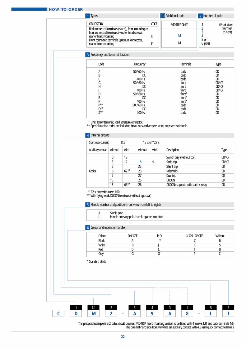
HOW TO ORDER
Frequency and terminal location
Number of polesAdditional codeT y p e s
* Line: screw terminal; load: pressure connector.** Special traction codes are including break nuts and ampere rating engraved on handle.
* Standard black
22
1 21.1
I6
L5
84
A3
94
A3
22
D1
C --
The proposed example is a 2 poles circuit breaker, MID-TRIP, front mounting version to be fitted with 4 screws M4 and back terminals M5.The pole left-hand side front view has an auxiliary contact with 4,8 mm quick connect terminals.
* 22 x only with curve 100.** With flying leads DUCON terminals (without approval)
C o l o u r O N / O F F I / O I/ON O/OFF W i t h o u tB l a c k A I* C RW h i t e B J K SR e d D L T UG r e y G O P Z
A Single poleL Handle on every pole, handle spacers mounted
C o d e F r e q u e n c y T e r m i n a l s T y p e
A 50/60 Hz b a c k C DB D C b a c k C DC 400 Hz b a c k C DG 50/60 Hz f r o n t C D / C FH D C f r o n t C D / C FJ 400 Hz f r o n t C D / C FD 50/60 Hz f r o n t * C DE D C f r o n t * C DF 400 Hz f r o n t * C DP * * 50 /60 Hz b a c k C DQ * * D C b a c k C DS * * 400 Hz b a c k C D
O B L I G A T O R Y C O D EBack-connected terminals (studs), front mounting orfront connected terminals (washer-head screw), rear or front mounting DFront connected terminals (pressure connector), rear or front mounting F
MID-TRIP ONLY
M
M
1 (Front view2 from left3 to right)45 o r6 p o l e s
3
Internal circuits4
Handle number and position (front view from left to right)5
Colour and inprint of handle 6
M1.1
Start over-current 8 x 15 x or *22 x
Auxiliary contact w i t h o u t w i t h w i t h o u t w i t h D e s c r i p t i o n T y p e
0 1 2 Switch only (without coil) C D / C F3 2 8 9 Serie trip C D / C F5 2 2 Shunt trip C D
C o d e s 6 6 2 * * 2 3 Relay trip C D7 2 7 Dual trip C D
1 5 2 5 D U C O N C D1 6 6 3 * * 2 6 DUCON (separate coil) serie + relay C D

x x x x x / x x x x xUn or In coil U = contact voltage
x x x x x / x x x x x / x x x x xUn or In coil In contact U = contact voltage
x x x x x / x x x x x / x x x x xIn main coil U = contact Un 2nd coil
v o l t a g e
A ) To repeat only if poles are different. For breakers with coilin series with contacts, indicate:
B ) For breakers with coil circuit separated of contact circuit,indicate: (internal circuits: 6, 23 and 62)Un possible: (24-250 V AC) (4-125 V DC)
C ) For breakers with two coils, indicate: (internal circuits: 7,15, 16, 25, 26, 27 and 63)Un only possible for 2nd coil: (4-240V AC) (4-125 V DC)
* 52 : standard Dimensions: See pages 19 and 20* *U L / C S A 15 A/480 V A C 2 A/600 V A C
* Available only with internalcircuits codes 0, 2, 3, 5, 8,9, 12, 16, 22, 25 and 26
* L : See page 14 ** for VDE approval : up to 50 A
23
Each pole 5 Amps In with motor start delay curve, 15 x In high-inrush = 75 Amps during 10 ms.This selected type of circuit breaker is UL-CSA approved at 277 V AC.
157
- D8
- L9
- 0710
- 511
- 1012
-
Fixing inserts + other mount and terminals7
C o d e I n s e r t s T e r m i n a l s *L (mm) C o d e I n s e r t s T e r m i n a l s
1 5 M 4 Up to 50 A : M 5 1 6 0 1 6 - 3 2 Up to 100 A : M10 x 1 (CF)1 6 M 4 Up to 100 A : M 6 1 9 0 4 M 4 Up to 100 A : M10 x 1 (CF)0 7 6 - 3 2 Up to 50 A : 1 0 - 3 2 1 6 0 1 6 - 3 2 Up to 100 A : **10-32 (CD)
B a c k - 0 9 6 - 3 2 Up to 100 A : 1/ 4 - 2 0 1 9 F r o n t - 0 4 M 4 Up to 100 A : **M5 (CD)c o n n e c t e d 2 7 M 4 Up to 100 A : M 6 3 0 c o n n e c t e d 0 6 M 4 Up to 100 A : M6 (CD)t e r m i n a l s 2 8 M 4 Up to 100 A : M 6 4 5 t e r m i n a l s
( C D ) 2 9 M 4 Up to 100 A : M 6 5 5 ( C D )3 7 M 4 Up to 50 A : 1 0 - 3 2 1 63 8 M 4 Up to 100 A : 1/ 4 - 2 0 1 93 9 6 - 3 2 Up to 50 A : M 5 1 64 0 6 - 3 2 Up to 100 A : M 6 1 9
Code VDE Code UL-CSA9
D Standard withoutVDE approval
H* Approval D I N EN 60947-2 in conformity with IEC 950
W In conformity withIEC 950
U Up to 240 V 50/60 Hz - 125 V DC : Listed UL 489 (General purpose)D U Up to 240 V 50/60 Hz - 125 V : Listed UL 489 (Special purpose)A Up to 240 V 50/60 Hz/400 Hz : Recognized UL 508L Up to 277 V 50/60 Hz : Recognized UL 508N L Up to 277 V 50/60 Hz : Without UL-CSA approvalA B Up to 480 V 50/60 Hz : Recognized UL 508 (Only with 2 poles minimum)N B Up to 480 V 50/60 Hz : Without UL-CSA approvalA E Up to 600 V 50/60 Hz : Recognized UL 508 (Only with 2 poles minimum)N E Up to 600 V 50/60 Hz : Without UL-CSA approvalD C Up to 125 V DC : Recognized UL 508D Up to 240 V 50/60 Hz / 400 Hz - 125 V DC : Recognized UL 1077N U Up to 240 V 50/60 Hz / 400 Hz - 125 V DC : Without UL-CSA approval
Auxiliary contacts10
Voltage or current rating V or A11
I max. (A) at 220 V ACC o d e F u n c t i o n C o n t a c t T e r m i n a l s UL / CSA V D E0 7 NO - NC A g 4,8 fast-on 1 0 . 1 -5 2 * NO - NC A g 2,8 fast-on 1 0 . 1 15 4 NO - NC A g A u P t 2,8 fast-on 0 . 1 0 . 1T S NO - NC A g 6-32 screws and cup washers * * 1 . 5
Time delay curves12 Additional note
See pages 7 to 11 The internal circuits 6, 16, 23, 26, 62 and 63 have a standard dielectric strength of 2 x Un + 1000 V. For 2500 V indicate code HV.For 2500 V with protected terminals indicate code HF.For only protected terminals indicate code F.
8

24
NOTES

For the Widest Selection of Circuit Protection, from 0.01 to 1200 Amperes,look to Heinemann.
Circuit Breaker Selection Guide
Eaton SACommercial Controls DivisionHeinemann ProductsCH - 1345 Le Lieu, SwitzerlandTel ++41 21 841 18 41Fax ++41 21 841 15 43
Highly Reliable MiniatureCircuit Protectors and Hydraulic-Magnetic Circuit Breakers
Ampere Rating (A) Interrupting Capacity (A)