series cl - ck - contactors - vox...
TRANSCRIPT
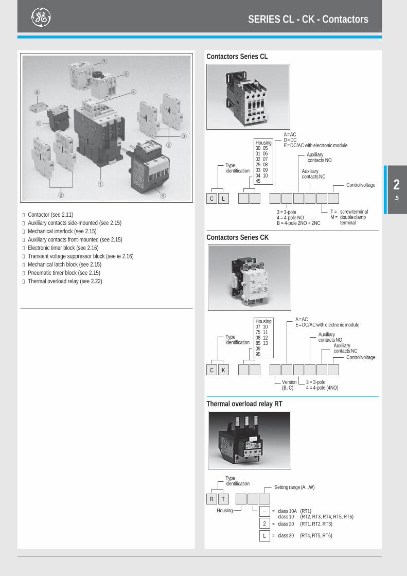
Contactors Series CL
C L
Typeidentification
Control voltage
T = screw terminalM = double clamp
terminal
3 = 3-pole4 = 4-pole NOB = 4-pole 2NO + 2NC
Contactors Series CK
Auxiliarycontacts NC
Auxiliary contacts NO
A=ACD=DCE=DC/AC with electronic module
① Contactor (see 2.11)② Auxiliary contacts side-mounted (see 2.15)③ Mechanical interlock (see 2.15)④ Auxiliary contacts front-mounted (see 2.15)⑤ Electronic timer block (see 2.16)⑥ Transient voltage suppressor block (see ie 2.16)⑦ Mechanical latch block (see 2.15)⑧ Pneumatic timer block (see 2.15)⑨ Thermal overload relay (see 2.22)
Housing00 0501 0602 0725 0803 0904 1045
C K
Typeidentification
A=ACE=DC/AC with electronic module
Thermal overload relay RT
Housing07 1075 1108 1285 130995
Auxiliarycontacts NO
Auxiliarycontacts NC
Control voltage
Version(B, C)
3 = 3-pole4 = 4-pole (4NO)
= class 30 (RT4, RT5, RT6)
= class 10A (RT1)class 10 (RT2, RT3, RT4, RT5, RT6)
Typeidentification
R T
Housing
Setting range (A...W)
L
= class 20 (RT1. RT2. RT3)2
–
SERIES CL - CK - Contactors
2.5
Three-pole contactorsfrom 9 to 105A (AC3)
Control circuit: alternating current
Spare coils Alternating current CL00 - CL25 LB1A 0.063CL03 - CL45 LB3A 0.102CL06 - CL10 LB4A 0.145
Available coil voltages (1)
Alternating current (V)
C D F G J K M N R U V W X Y Z
50Hz 24 42 48 110 220 240 380 415 440 500 660230 400 690
– Power circuit (AC): up to 690V– Control circuit:
Alternating current up to 690V AC– Terminal numbering in accordance with
EN 50005 and EN 50012– Fixing by clipping onto 35 mm DIN rail
EN 50022-35 or by screws– Degree of protection CL00... to CL02... : IP20
CL25... to CL10... : IP10– Screws protected against accidental contact in
accordance with VDE 0106.– Three coil terminals.– Accessories:
Mounting possibilities of front/sideinstantaneous auxiliary contact blocks, timedauxiliary contact blocks, mechanical latch,transient suppressor block and interfacemodules
– Maximum number of auxiliary contacts:four for CL00...CL25six for CL03...CL45eight for CL06...CL10
CL00A310TN
CL45A300MN
CL07A300MN
(1) To complete the catalogue number, replace the symbol by the codecorresponding to the voltage and frequency of the control circuit.
(2) Equipped with one block BCLF (see 2.15)(3) Equipped with two blocks BCLF (see 2.15)
Max. operat. current Admissible power AC3 Elec. endur. Aux. contacts Cat. no. (1) Weight
Non- Motors 220V 380V 415V 500V Categoryinductive ≤≤≤≤≤ 440V 230V 400V 440V AC3load 3-phase
50/60 HzAC1 AC3
A A kW kW kW kW # ops.
25 9 2.2 4 4 5.5 2 x 10⁶ 0 0 CL00A300T 0.2801 0 CL00A310T 0.2950 1 CL00A301T 0.295
25 12 3 5.5 5.5 7.5 2 x 10⁶ 0 0 CL01A300T 0.2801 0 CL01A310T 0.2950 1 CL01A301T 0.295
32 18 4 7.5 7.5 10 1.7 x 10⁶ 0 0 CL02A300T 0.2801 0 CL02A310T 0.2950 1 CL02A301T 0.295
45 25 7.5 11 11 15 2 x 10⁶ 0 0 CL25A300T 0.2701 0 CL25A310T (2) 0.2850 1 CL25A301T (2) 0.285
45 25 7.5 12 12 15 2 x 10⁶ 1 0 CL03A310M 0.4900 1 CL03A301M 0.490
60 32 9 16 16 18.5 2 x 10⁶ 0 0 CL04A300M 0.5001 0 CL04A310M 0.5200 1 CL04A301M 0.520
60 40 11 18.5 22 25 2 x 10⁶ 0 0 CL45A300M 0.4901 1 CL45A311M (3) 0.540
90 50 15 22 25 30 1.8 x 10⁶ 0 0 CL06A300M 1.0751 1 CL06A311M (3) 1.105
110 65 18.5 30 37 40 1.7 x 10⁶ 0 0 CL07A300M 1.0901 1 CL07A311M (3) 1.120
110 80 22 37 45 45 1.5 x 10⁶ 0 0 CL08A300M 1.1101 1 CL08A311M (3) 1.130
140 95 25 45 50 55 1.7 x 10⁶ 0 0 CL09A300M 1.0001 1 CL09A311M (3) 1.450
140 105 30 55 55 65 1.5 x 10⁶ 0 0 CL10A300M 1.4401 1 CL10A311M (3) 1.470
•3 •1
•2•4
Thermal overload relay, see 2.22Technical specifications, see 2.34Dimensions, see 2.44
SERIES CL - Contactors
2.11
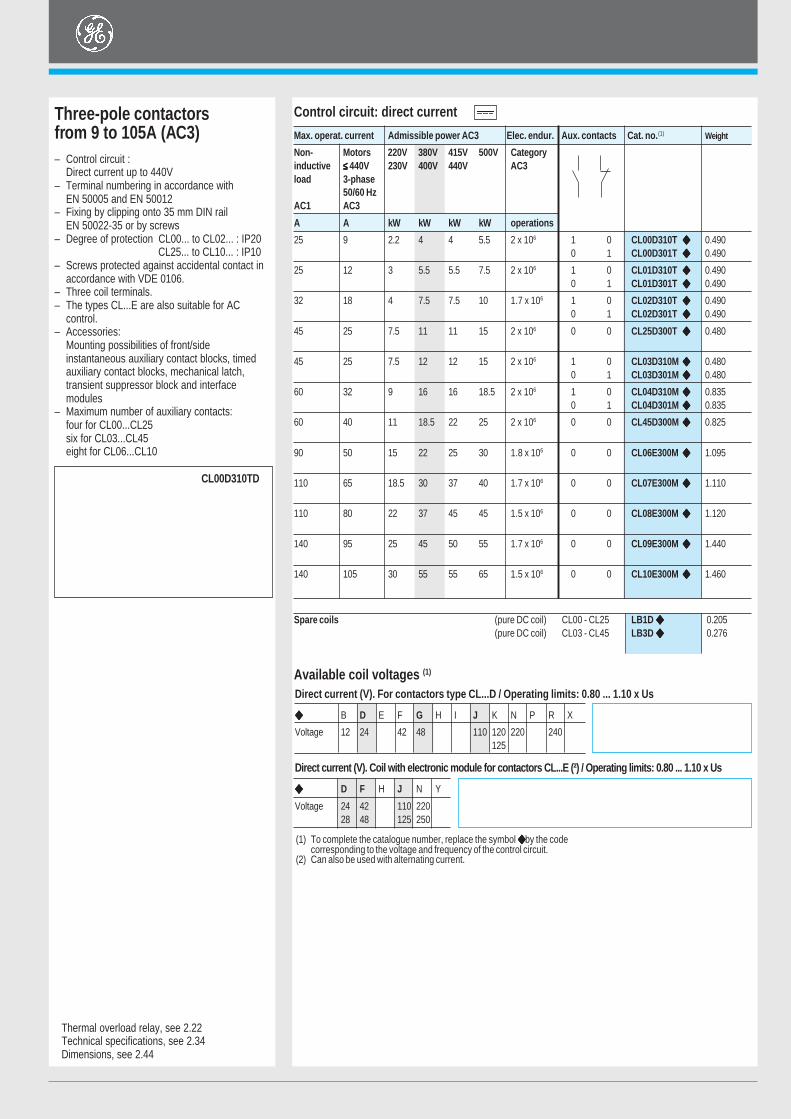
Three-pole contactorsfrom 9 to 105A (AC3)
Control circuit: direct current
CL00D310TD
– Control circuit :Direct current up to 440V
– Terminal numbering in accordance withEN 50005 and EN 50012
– Fixing by clipping onto 35 mm DIN railEN 50022-35 or by screws
– Degree of protection CL00... to CL02... : IP20CL25... to CL10... : IP10
– Screws protected against accidental contact inaccordance with VDE 0106.
– Three coil terminals.– The types CL...E are also suitable for AC
control.– Accessories:
Mounting possibilities of front/sideinstantaneous auxiliary contact blocks, timedauxiliary contact blocks, mechanical latch,transient suppressor block and interfacemodules
– Maximum number of auxiliary contacts:four for CL00...CL25six for CL03...CL45eight for CL06...CL10
Max. operat. current Admissible power AC3 Elec. endur. Aux. contacts Cat. no. (1) Weight
Non- Motors 220V 380V 415V 500V Categoryinductive ≤≤≤≤≤ 440V 230V 400V 440V AC3load 3-phase
50/60 HzAC1 AC3
A A kW kW kW kW operations
25 9 2.2 4 4 5.5 2 x 10⁶ 1 0 CL00D310T 0.4900 1 CL00D301T 0.490
25 12 3 5.5 5.5 7.5 2 x 10⁶ 1 0 CL01D310T 0.4900 1 CL01D301T 0.490
32 18 4 7.5 7.5 10 1.7 x 10⁶ 1 0 CL02D310T 0.4900 1 CL02D301T 0.490
45 25 7.5 11 11 15 2 x 10⁶ 0 0 CL25D300T 0.480
45 25 7.5 12 12 15 2 x 10⁶ 1 0 CL03D310M 0.4800 1 CL03D301M 0.480
60 32 9 16 16 18.5 2 x 10⁶ 1 0 CL04D310M 0.8350 1 CL04D301M 0.835
60 40 11 18.5 22 25 2 x 10⁶ 0 0 CL45D300M 0.825
90 50 15 22 25 30 1.8 x 10⁶ 0 0 CL06E300M 1.095
110 65 18.5 30 37 40 1.7 x 10⁶ 0 0 CL07E300M 1.110
110 80 22 37 45 45 1.5 x 10⁶ 0 0 CL08E300M 1.120
140 95 25 45 50 55 1.7 x 10⁶ 0 0 CL09E300M 1.440
140 105 30 55 55 65 1.5 x 10⁶ 0 0 CL10E300M 1.460
Thermal overload relay, see 2.22Technical specifications, see 2.34Dimensions, see 2.44
Available coil voltages (1)
(1) To complete the catalogue number, replace the symbol by the codecorresponding to the voltage and frequency of the control circuit.
(2) Can also be used with alternating current.
Direct current (V). For contactors type CL...D / Operating limits: 0.80 ... 1.10 x Us
B D E F G H I J K N P R X
Voltage 12 24 42 48 110 120 220 240125
Direct current (V). Coil with electronic module for contactors CL...E (²) / Operating limits: 0.80 ... 1.10 x Us
D F H J N Y
Voltage 24 42 110 22028 48 125 250
Spare coils (pure DC coil) CL00 - CL25 LB1D 0.205(pure DC coil) CL03 - CL45 LB3D 0.276
(coil + electronic module) CL06 - CL10 LB4E 0.610
•3 •1
•2•4
SERIES CL - Contactors
2.12
Four-pole contactors (4NO)from 25 to 140A (AC1)
Control circuit: alternating current
– Power circuit (AC): up to 690V– Control circuit:
Alternating current up to 690V ACDirect current up to 440V DC
– Terminal numbering in accordance withEN 50005 and EN 50012
– Fixing by clipping onto 35 mm DIN rail(EN 50022-35) or by screws.
– Degree of protection CL01... to CL02... : IP20CL03... to CL09... : IP10
– Screws protected against accidental contact inaccordance with VDE 0106.
– Three coil terminals.– The types CL...E are also suitable for AC
control.– Accessories:
Mounting possibilities of front/side instantaneousauxiliary contact blocks, timed auxiliary contactblocks, mechanical latch, transient suppressorblock and interface modules.
Available coil voltages (1)
(1) To complete the catalogue number, replace the symbol by the codecorresponding to the voltage and frequency of the control circuit.
(2) Only for CL00 to CL45.
Thermal overload relay, see 2.21Technical specifications, see 2.34Dimensions, see 2.44
Control circuit: direct current
25 12 9.5 16.5 18 21.5 1.5 x 10⁶ DC 4 0 CL01D400T 0.490
32 18 12 22 23 27.5 1.5 x 10⁶ DC 4 0 CL02D400T 0.490
45 25 17 29 32 39 2 x 10⁶ DC 4 0 CL03D400M 0.825
60 32 22.5 39.5 43 52 1.5 x 10⁶ DC 4 0 CL04D400M 0.835
90 50 34 59 64 78 1.5 x 10⁶ AC/DC 4 0 CL05E400M 1.290
110 65 42 72.5 79 95 1.8 x 10⁶ AC/DC 4 0 CL07E400M 1.290
140 95 53 92 100 121 1.8 x 10⁶ AC/DC 4 0 CL09E400M 1.500
Spare coils (pure DC coil) CL00 - CL02 LB1D 0.205(pure DC coil) CL03 - CL04 LB3D 0.276
(coil + electronic module) CL05 - CL09 LB4E 0.610
Spare coils CL01 - CL02 LB1A 0.063CL03 - CL04 LB3A 0.102CL05 - CL09 LB4A 0.145
CL01A400TN
CL05A400MN
CL09E400MJ
Alternating current (V)
Direct current (V). For contactors type CL...D / 0.80 ... 1.10 x Us (4)
B D E F G H I J K N P R X
Voltage 12 24 42 48 110 120 220 240125
Direct current (V). Coil with electronic module for contactors type CL...E (3) / 0.80 ... 1.10 x Us (4)
D F H J N Y
Voltage 24 42 110 22028 48 125 250
C D F G H J K M N R S T U V W X Y Z
50Hz 24 42 48 110 127 220 240 380 415 440 500 660230 400 690
Maximum operating Admissible Electrical Control Power Cat. no. (1) Weightcurrent power AC1 endurance circuit contacts
Non- 220V 380V 415V 500V Categoryinductive 230V 400V 440V AC1loadAC1 AC3
A A kW kW kW kW operations
25 12 9.5 16.5 18 21.5 1.5 x 10⁶ AC 4 0 CL01A400T 0.280
32 18 12 22 23 27.5 1.5 x 10⁶ AC 4 0 CL02A400T 0.280
45 25 17 29 32 39 2 x 10⁶ AC 4 0 CL03A400M 0.490
60 32 22.5 39.5 43 52 1.5 x 10⁶ AC 4 0 CL04A400M 0.500
90 50 34 59 64 78 1.5 x 10⁶ AC 4 0 CL05A400M 1.240
110 65 42 72.5 79 95 1.8 x 10⁶ AC 4 0 CL07A400M 1.270
140 95 53 92 100 121 1.8 x 10⁶ AC 4 0 CL09A400M 1.450
SERIES CL - Contactors
2.13
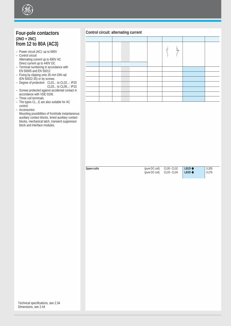
Control circuit: alternating currentFour-pole contactors(2NO + 2NC)from 12 to 80A (AC3)– Power circuit (AC): up to 690V– Control circuit:
Alternating current up to 690V ACDirect current up to 440V DC
– Terminal numbering in accordance withEN 50005 and EN 50012
– Fixing by clipping onto 35 mm DIN rail(EN 50022-35) or by screws.
– Degree of protection CL01... to CL02...: IP20CL03... to CL09...: IP10
– Screws protected against accidental contact inaccordance with VDE 0106.
– Three coil terminals.– The types CL...E are also suitable for AC
control.– Accessories:
Mounting possibilities of front/side instantaneousauxiliary contact blocks, timed auxiliary contactblocks, mechanical latch, transient suppressorblock and interface modules.
Technical specifications, see 2.34Dimensions, see 2.44
Spare coils (pure DC coil) CL00 - CL02 LB1D 0.205(pure DC coil) CL03 - CL04 LB3D 0.276
(coil + electronic module) CL05 - CL08 LB4E 0.610
Control circuit: direct current
25 12 3 5.5 5.5 7.5 DC 2 2 CL01DB00T 0.490
32 18 4 7.5 7.5 10 DC 2 2 CL02DB00T 0.490
45 25 7.5 12 12 15 DC 2 2 CL03DB00M 0.825
60 32 9 16 16 18.5 DC 2 2 CL04DB00M 0.835
90 40 11 18.5 22 25 DC/AC 2 2 CL05EB00M 1.290
110 65 18.5 30 37 40 DC/AC 2 2 CL07EB00M 1.320
110 80 22 37 45 45 DC/AC 2 2 CL08EB00M 1.320
Spare coils CL01 - CL02 LB1A 0.063CL03 - CL04 LB3A 0.102CL05 - CL08 LB4A 0.145
Available coil voltages (1)
Alternative current (V)
(1) To complete the catalogue number, replace the symbol by the codecorresponding to the voltage and frequency of the control circuit.
(2) Only for CL00 to CL45.
Direct current (V). For contactors type CL...D
B D E F G H I J K N P R X
Voltage 12 24 42 48 110 120 220 230 240125
Direct current (V). Coil with electronic module for contactors type CL...E (³)
D F H J N Y
Voltage 24 42 110 22028 48 125 250
CL01AB00TN
CL05EB00MJ
C D F G H J K M N R S T U V W X Y Z
50Hz 24 42 48 110 127 220 240 380 415 440 500 660230 400 690
Max. operat. current Admissible power AC3 Control Power contacts Cat. no. (1) Weight
Non- Motors 220V 380V 415V 500Vinductive ≤≤≤≤≤ 440V, 230V 400V 440Vload 3-phase
50/60 HzAC1 AC3
A A kW kW kW kW
25 12 3 5.5 5.5 7.5 AC 2 2 CL01AB00T 0.280
32 18 4 7.5 7.5 10 AC 2 2 CL02AB00T 0.280
45 25 7.5 12 12 15 AC 2 2 CL03AB00M 0.490
60 32 9 16 16 18.5 AC 2 2 CL04AB00M 0.500
90 40 11 18.5 22 25 AC 2 2 CL05AB00M 1.240
110 65 18.5 30 37 40 AC 2 2 CL07AB00M 1.270
110 80 22 37 45 45 AC 2 2 CL08AB00M 1.270
SERIES CL - Contactors
2.14
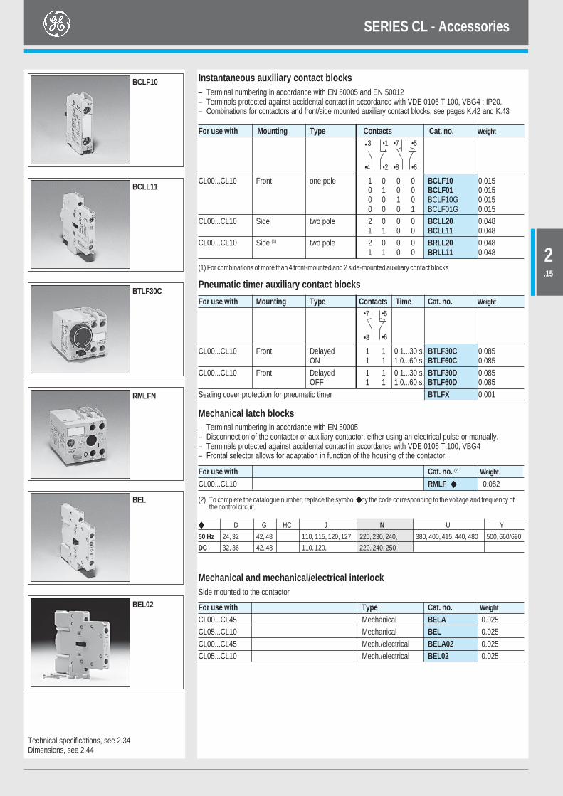
Instantaneous auxiliary contact blocks– Terminal numbering in accordance with EN 50005 and EN 50012– Terminals protected against accidental contact in accordance with VDE 0106 T.100, VBG4 : IP20.– Combinations for contactors and front/side mounted auxiliary contact blocks, see pages K.42 and K.43
For use with Mounting Type Contacts Cat. no. Weight
CL00...CL10 Front one pole 1 0 0 0 BCLF10 0.0150 1 0 0 BCLF01 0.0150 0 1 0 BCLF10G 0.0150 0 0 1 BCLF01G 0.015
CL00...CL10 Side two pole 2 0 0 0 BCLL20 0.0481 1 0 0 BCLL11 0.048
CL00...CL10 Side (1) two pole 2 0 0 0 BRLL20 0.0481 1 0 0 BRLL11 0.048
(1) For combinations of more than 4 front-mounted and 2 side-mounted auxiliary contact blocks
Pneumatic timer auxiliary contact blocks
Technical specifications, see 2.34Dimensions, see 2.44
Mechanical latch blocks– Terminal numbering in accordance with EN 50005– Disconnection of the contactor or auxiliary contactor, either using an electrical pulse or manually.– Terminals protected against accidental contact in accordance with VDE 0106 T.100, VBG4– Frontal selector allows for adaptation in function of the housing of the contactor.
D G HC J N U Y
50 Hz 24, 32 42, 48 110, 115, 120, 127 220, 230, 240, 380, 400, 415, 440, 480 500, 660/690
DC 32, 36 42, 48 110, 120, 220, 240, 250
Mechanical and mechanical/electrical interlockSide mounted to the contactor
For use with Type Cat. no. Weight
CL00...CL45 Mechanical BELA 0.025CL05...CL10 Mechanical BEL 0.025CL00...CL45 Mech./electrical BELA02 0.025CL05...CL10 Mech./electrical BEL02 0.025
(2) To complete the catalogue number, replace the symbol by the code corresponding to the voltage and frequency ofthe control circuit.
For use with Cat. no. (2) Weight
CL00...CL10 RMLF 0.082
For use with Mounting Type Contacts Time Cat. no. Weight
CL00...CL10 Front Delayed 1 1 0.1...30 s. BTLF30C 0.085ON 1 1 1.0...60 s. BTLF60C 0.085
CL00...CL10 Front Delayed 1 1 0.1...30 s. BTLF30D 0.085OFF 1 1 1.0...60 s. BTLF60D 0.085
Sealing cover protection for pneumatic timer BTLFX 0.001
BCLL11
BTLF30C
RMLFN
BCLF10
BEL
BEL02
•6•8
•7 •5
•3
•4 •2
•7
•8
•5
•6
•1
SERIES CL - Accessories
2.15
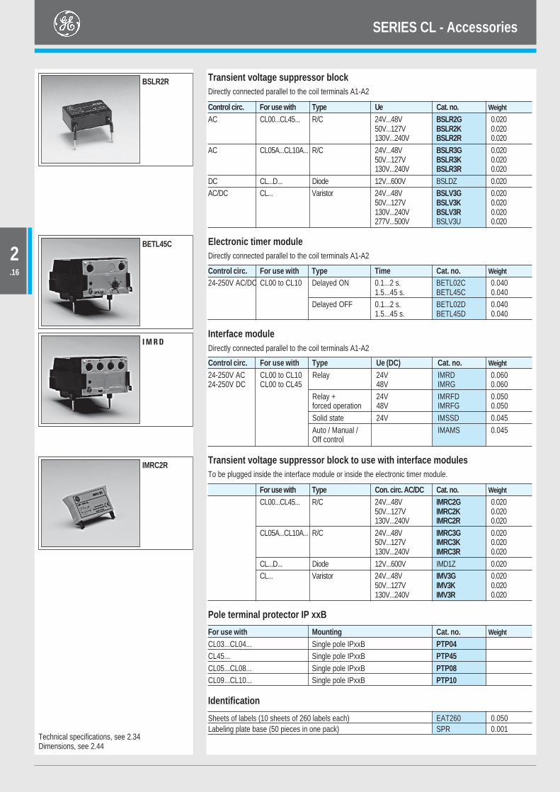
Transient voltage suppressor blockDirectly connected parallel to the coil terminals A1-A2
Control circ. For use with Type Ue Cat. no. Weight
AC CL00...CL45... R/C 24V...48V BSLR2G 0.02050V...127V BSLR2K 0.020130V...240V BSLR2R 0.020
AC CL05A...CL10A... R/C 24V...48V BSLR3G 0.02050V...127V BSLR3K 0.020130V...240V BSLR3R 0.020
DC CL...D... Diode 12V...600V BSLDZ 0.020AC/DC CL... Varistor 24V...48V BSLV3G 0.020
50V...127V BSLV3K 0.020130V...240V BSLV3R 0.020277V...500V BSLV3U 0.020
Electronic timer moduleDirectly connected parallel to the coil terminals A1-A2
Interface moduleDirectly connected parallel to the coil terminals A1-A2
Pole terminal protector IP xxB
Control circ. For use with Type Time Cat. no. Weight
24-250V AC/DC CL00 to CL10 Delayed ON 0.1...2 s. BETL02C 0.0401.5...45 s. BETL45C 0.040
Delayed OFF 0.1...2 s. BETL02D 0.0401.5...45 s. BETL45D 0.040
Control circ. For use with Type Ue (DC) Cat. no. Weight
24-250V AC CL00 to CL10 Relay 24V IMRD 0.06024-250V DC CL00 to CL45 48V IMRG 0.060
Relay + 24V IMRFD 0.050forced operation 48V IMRFG 0.050Solid state 24V IMSSD 0.045Auto / Manual / IMAMS 0.045Off control
For use with Mounting Cat. no. Weight
CL03...CL04... Single pole IPxxB PTP04CL45... Single pole IPxxB PTP45CL05...CL08... Single pole IPxxB PTP08CL09...CL10... Single pole IPxxB PTP10
Technical specifications, see 2.34Dimensions, see 2.44
BETL45C
BSLR2R
Transient voltage suppressor block to use with interface modulesTo be plugged inside the interface module or inside the electronic timer module.
I M R D
IMRC2R
Identification
Sheets of labels (10 sheets of 260 labels each) EAT260 0.050Labeling plate base (50 pieces in one pack) SPR 0.001
For use with Type Con. circ. AC/DC Cat. no. Weight
CL00...CL45... R/C 24V...48V IMRC2G 0.02050V...127V IMRC2K 0.020130V...240V IMRC2R 0.020
CL05A...CL10A... R/C 24V...48V IMRC3G 0.02050V...127V IMRC3K 0.020130V...240V IMRC3R 0.020
CL...D... Diode 12V...600V IMD1Z 0.020CL... Varistor 24V...48V IMV3G 0.020
50V...127V IMV3K 0.020130V...240V IMV3R 0.020
SERIES CL - Accessories
2.16
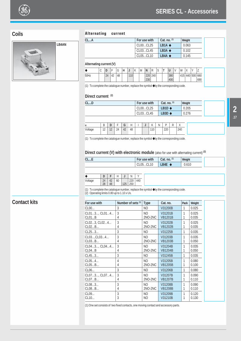
Coils Alternating current
(1) To complete the catalogue number, replace the symbol by the corresponding code.
LB4ANCL...A For use with Cat. no. (1) Weight
CL00...CL25 LB1A 0.063CL03...CL45 LB3A 0.102CL05...CL10 LB4A 0.145
Direct current (2)
u B D F G H I J K N P R XVoltage 12 12 24 42 48 110 220 240
(1) To complete the catalogue number, replace the symbol by the corresponding code.
Direct current (V) with electronic module (also for use with alternating current) (2)
CL...E For use with Cat. no. (1) Weight
CL05...CL10 LB4E 0.610
D F H J N YVoltage 24 42 60 220 440
28 48 125 250
(1) To complete the catalogue number, replace the symbol by the corresponding code.(2) Operating limits 0.80 up to 1.10 x Us.
(1) One set consists of two fixed contacts, one moving contact and accessory parts.
For use with Number of sets (1) Type Cat. no. Pack Weight
CL00... 3 NO V31200B 1 0.025CL01...3..., CL01...4... 3 NO V31201B 1 0.025CL01...B 4 2NO-2NC VB1201B 1 0.035CL02...3, CL02...4... 3 NO V31202B 1 0.025CL02...B... 4 2NO-2NC VB1202B 1 0.035CL25...3... 3 NO V31225B 1 0.035CL03...,CL03...4... 3 NO V31203B 1 0.035CL03...B... 4 2NO-2NC VB1203B 1 0.050CL04...3..., CL04...4... 3 NO V31204B 1 0.035CL04...B 4 2NO-2NC VB1204B 1 0.050CL45...3... 3 NO V31245B 1 0.035CL05...4... 4 NO V31205B 1 0.080CL05...B... 4 2NO-2NC VB1205B 1 0.100CL06... 3 NO V31206B 1 0.080CL07...3..., CL07...4... 3 NO V31207B 1 0.090CL07...B... 4 2NO-2NC VB1207B 1 0.110CL08...3... 3 NO V31208B 1 0.090CL08...B... 4 2NO-2NC VB1208B 1 0.110CL09... 3 NO V31209B 1 0.120CL10... 3 NO V31210B 1 0.130
CL...D For use with Cat. no. (1) Weight
CL00...CL25 LB1D 0.205CL03...CL45 LB3D 0.276
Alternating current (V)
C D F G H J K M N R S T U V W X Y Z
50Hz 24 42 48 110 220 240 380 415 440 500 660230 400 690
Contact kits
SERIES CL - Accessories
2.17
Power circuitThree-pole version
Four-pole version (4 NO and 2 NO + 2 NC)
(1) 2 NO + 2 NC only(2) 4 NO only
Three-pole and four-pole version
CL00 CL01 CL02 CL25 CL03 CL04 CL45 CL06 CL07 CL08 CL09 CL10Rated thermal current Ith at θ ≤ 55°C (A) 25 25 32 45 45 60 60 90 110 110 140 140Rated operational current Ie (A) 9 12 18 25 25 32 40 50 65 80 95 105Rated operational voltage Ue (V) 690 690 690 690 690 690 690 690 690 690 690 690
CL01 CL02 CL03 CL04 CL05 CL07 CL08(1) CL09(2)
Rated thermal current Ith at θ ≤ 55°C (A) 25 32 45 60 90 110 110 140Rated operational voltage Ue (V) 690 690 690 690 690 690 690 690
CL00 CL01 CL02 CL25 CL03 CL04 CL45 CL05 CL06 CL07 CL08 CL09 CL10Rated insulation voltage Ui (V) 1000 1000 1000 1000 1000 1000 1000 1000 1000 1000 1000 1000 1000Maximum continuous current AC1 (A) 25 25 32 45 45 60 60 90 90 110 110 140 140Frequency limits (Hz) 25..400 25..400 25..400 25..400 25..400 25..400 25..400 25..400 25..400 25..400 25..400 25..400 25..400Making capacity (RMS) (acc. IEC 947) (A) 450 450 450 450 550 550 550 1000 1000 1000 1000 1280 1280Breaking capacity (RMS) (acc. IEC 947)
Ue ≤ 400V (A) 250 250 250 350 450 450 450 920 920 920 920 1050 1050Ue = 500V (A) 250 250 250 320 450 450 450 920 920 920 920 1050 1050Ue = 690V (A) 130 130 130 170 205 205 205 780 780 780 780 950 950
Short-time current1 sec. (A) 455 455 570 630 1010 1010 1265 1580 1580 2530 2530 3300 33005 sec. (A) 205 205 254 280 450 450 450 565 710 1130 1130 1485 1485
10 sec. (A) 144 144 180 200 320 320 400 500 500 800 800 1050 105030 sec. (A) 85 85 104 115 185 185 230 290 290 460 460 600 6001 min. (A) 60 60 74 80 130 130 165 205 205 325 325 430 4303 min. (A) 35 35 46 50 90 90 100 120 120 185 185 250 250
Recovery time (min.) 10 10 10 10 10 10 10 10 10 10 10 10 10Protection against short-circuits with fuses
Coordination type "2"aM (A) 10 12 20 25 25 35 40 40 50 80 80 125 160gL-gG (A) 25 35 35 50 63 63 63 100 100 160 160 200 200
Without weldingaM (A) 8 8 16 20 20 20 25 35 40 50 50 80 80gL-gG (A) 10 10 25 35 35 35 50 80 80 100 100 160 160
Impedance per pole (mΩ) 2.35 2.35 2.41 1.65 1.28 1.28 0.95 0.85 0.85 0.86 0.86 0.76 0.76Power dissipation per pole
AC1 (W) 1.47 1.47 2.46 3.34 2.59 4.6 3.42 6.89 6.89 10.4 10.4 14.89 14.89AC3 (W) 0.19 0.34 0.78 1.03 0.80 1.31 1.52 1.36 2.12 3.63 5.5 6.86 8.37
Insulation resistanceBetween adjacent poles (MΩ) >10 >10 >10 >10 >10 >10 >10 >10 >10 >10 >10 >10 >10Between poles and earth (MΩ) >10 >10 >10 >10 >10 >10 >10 >10 >10 >10 >10 >10 >10Between input and output (MΩ) >10 >10 >10 >10 >10 >10 >10 >10 >10 >10 >10 >10 >10
SERIES CL - Technical data
2.35
Category AC3
Category AC4Category AC1
Electrical endurance
Number ofoperations
107
8
4
68
106
2
4
6
2 4 6 8 10 20 40 1008060 200 400Ic=Iefor all tensions
CL00
CL01
CLO
2
CL25
-CL0
3
CL45
CL04
CL06
CL07
CL08
CL09
CL10
Category AC2
1.1
1.5
2.2
3.7 4
5.5
7.5 11 15
18.5 22 25 30 37 45 55 75 90 100
2
CL01
CLO
2
CL25
-CL0
3
CL45
CL04
CL06
CL07
CL08
CL09
CL10
4 1086 20 20010060 8040
9 12 18 25 32 50 65 95105
2
106
86
4
2
105
86
CL00
0.55
0.75 554537302522
18.515117.57
5.543
2.2
1.5
1.1
5.5
2.2 907555453730
18.5154
3.7
1.5
1.1
7.5 11 22
220/230V
415/450V
380/400V
Number ofoperations
1.1
1.5
2.2
3.7 4
5.5
7.5 11 15
18.5 22 25 30 37 45 55 75 90 100
107
2
106
0.55
0.75 554537302522
18.515117.57
5.543
2.2
1.5
1.1
5.5
2.2 907555453730
18.5154
3.7
1.5
1.1
7.5 11 22
220/230V
415/440V
380/400V
Number ofoperations
CL00
CL01
CLO
2
CL25
-CL0
3
CL04
CL45
CL06
CL07
CL08
CL09
CL10
8
6
4
864
2 4 1086 20 20010060 8040
9 12 18 25 32 50 65 95105
4Number ofoperations
CL00
CL01
CLO
2
CL25
-CL0
3
CL04
CL45
CL06
CL07
CL08
CL09
CL10
36 120 360480
540
6002
6
4
106
8
2
12 24 48 60
54 10872 192150
240
300 630
4 1518
.5 22 25 30 37 45 55 75 9055
18.515117.57
5.5
22
220/230V
415/440V
380/400V
0.55
0.75 1.5
1.1 43
2.2 4537302522
2.2
1.5
1.1
5.54
3.7
7.5 11
18.515 55453730 9075
1.1
1.5
2.2
3.7
5.5
7.5 11 100
110
A
A
kW
kW
kW
kW
kW
kW
A
kW
kW
kW
A
Ratedmotorpower(Ic = 2.5 Ie)
Ratedmotorpower(Ic = Ie)
Ratedmotorpower(Ic = 6 Ie)
Mixed category AC4/AC3Electrical endurance for mixed category (AC3/AC4) is calculated with thefollowing formula :
SERIES CL - Technical data
2.36
Direct current
Alternating current
Control circuitThree-pole and four-pole contactors
CL00D...CL25D CL03D...CL45D CL05E...CL08E CL09E...CL10ERated insulation voltage Ui (V) 1000 1000 1000 1000Standard voltages Us (V) 12...440 12...440 24...440 24...440Operating limits
Operating xUs 0.8...1.1 0.8...1.1 0.8...1.1 0.8...1.1Pick-up xUs 0.45...0.65 0.45...0.65 0.70...0.80 0.70...0.80Drop-out xUs 0.15...0.3 0.15...0.3 0.4...0.6 0.4...0.6
ConsumptionMagnetic circuit closed (W) 5.5 8 10 10Magnetic circuit open (W) 5.5 8 170 170
Opening and closing timesValues between + 10 % Us and – 20 % Us
Making time on excitation (NO contact) (ms) 35...65 35...70 60...80 60...80Breaking time on de-excitation (NO contact) (ms) 6...15 40...65 40...50 40...50
Values at UsMaking time on excitation (NO contact) (ms) 35...45 40...55 50...60 50...60Breaking time on de-excitation (NO contact) (ms) 7...12 30...65 55...60 55...60
Mechanical endurance 106 ops. 15 15 12 12Maximum rate
No load ops./h 3600 3600 2500 2500AC1 and AC3 at rated power ops./h 1200 1200 1200 600AC4 at rated power ops./h 360 360 200 200
CL00...CL25 CL03...CL45 CL05...CL08 CL09...CL10Rated insulation voltage Ui (V) 1000 1000 1000 1000Standard voltages Us 50 Hz (V) 24...690 24...690 24...690 24...690Voltage operating limits monofrequency coils
Operating xUs 0.8...1.1 0.8...1.1 0.8...1.1 0.8...1.1Pick-up xUs 0.6...0.8 0.65...0.8 0.65...0.8 0.65...0.8Seal xUs 0.35...0.55 0.4...0.6 0.4...0.6 0.4...0.6
Consumption monofrequency coilsSeal (VA) 6 9 15.5 15.5Pick-up (VA) 45 88 191 191
Thermal power dissipation (50 Hz/60 Hz)) (W) 2 / 1.7 2.8 / 3.3 4.5 / 3.9 4.5 / 3.9Power factor
Magnetic circuit closed (cos j) 0.39 0.31 0.35 0.35Magnetic circuit open (cos j) 0.82 0.76 0.64 0.64
Opening and closing timesValues between + 10 % Us and – 20 % Us
Making time on excitation (NO contact) (ms) 6...20 7...25 9...35 9...35Breaking time on de-excitation (NO contact) (ms) 6...13 5...25 9...15 9...15
Values at UsMaking time on excitation (NO contact) (ms) 8...20 10...19 15...30 15...30Breaking time on de-excitation (NO contact) (ms) 6...13 5...25 9...15 9...15
Mechanical enduranceMonofrequency coils 106 ops. 15 15 15 15Bifrequency coils (at 50 Hz)106 ops. 10 10 8 8
Maximum rateMonofrequency coils no load ops./h 9000 9000 9000 5000
AC1 at rated power ops./h 1200 1200 1200 1200AC2 at rated power ops./h 1000 1000 1000 750AC3 at rated power ops./h 1200 1200 1200 600AC4 at rated power ops./h 360 360 200 200
SERIES CL - Technical data
2.37
Internal auxiliary contacts
Auxiliary contact blocksInstantaneous blocks Timed blocksBCLF..., BCLL..., BRLL BTLF...
Rated insulation voltage (Ui) according to IEC 947 (V) 1000 1000Rated thermal current lth at θ ≤ 55°C (A) 10 10Making capacity (Ieff) according to IEC
AC15/AC11 Ue ≤ 400V, 50/60 Hz (A) 90 90DC 13/DC11 Ue ≤ 220V DC (A) 90 90
Breaking capacity (Ieff) according to IEC 947AC15/AC11 Ue ≤ 400V, 50/60 Hz (A) 60 60DC13/DC11 Ue ≤ 220V, DC (A) 0.95 0.95
AC15 Rated voltage and current Ue-Ie according to IEC 120/110V-6A 230/220V-6A 120/110V-6A 230/220V-6A400/380V-4A 440/415V-3.5A 400/380V-4A 440/415V-3.5A500V-2.5A 690/660V-1.5A 500V-2.5A 690/660V-1.5A
according to UL, CSA A600 A600DC13 Rated voltage and curent Ue-Ie according to IEC 24V-4A 48V-2A 110V-0.7A 24V-4A 48V-2A 110V-0.7A
220V-0.3A 440V-0.15A 220V-0.3A 440V-0.15Aaccording to UL, CSA Q600 Q600
Electrical endurance 106 ops. 1 1Mechanical endurance 106 ops. 10 5Minimum operational current (operational safety) 17V - 5mA 17V - 5mAShort-circuit protection Max. fuse class gl-gG without welding (A) 10 10Insulation resistance Between contacts (MΩ) > 10 > 10
Between contacts and earth (MΩ) > 10 > 10Between input and output (MΩ) > 10 > 10
Guaranteed no overlap between NO and NC contactsSpace (mm) 1.3 1.3Time (ms) 1.5 5
Impedance of the contacts (mΩ) 1.28 1.28Timing (ambient temperature between – 25°C and + 55°C)
Accuracy – ± 5%Loss of accuracy after 0.5 x 10⁶ ops. – + 20%Loss of accuracy per rise °C (0 - 55°C) – + 0.75% per °C
CL00...CL02 CL03-CL04Rated insulation voltage Ui according to IEC 947 (V) 1000 1000Rated thermal current Ith at θ ≤ 55°C (A) 20 20Making capacity (r.m.s.) according to IEC 947
AC15/AC11 Ue ≤ 400V, 50/60 Hz (A) 250 250DC13/DC11 Ue ≤ 220V DC (A) 250 250
Breaking capacity (r.m.s.) according to IEC 947AC15/AC11 Ue ≤ 400V, 50/60 Hz (A) 250 250DC13/DC11 Ue ≤ 220V DC (A) 2 2
AC 15 Rated voltage and current Ue-Ie according to IEC 110/120V-10A 220/230V-10A 110/120V-10A 230/220V-10A400/380V-6A 415/450V-5A 400/380V-6A 415/450V-5A500V-4A 690/660V-2A 500V-4A 690/660V-2A
according to UL, CSA A600 A600DC 13 Rated voltage and current Ue-le according to IEC 24V-6A 48V-4A 110V-2A 24V-6A 48V-4A 110V-2A
220V-0.7A 440V-0.7A 220V-0.7A 440V-0.7Aaccording to UL, CSA P600 P600
Electrical endurance ops. 106 106
Minimum operational power (operational safety) 17V - 5mA 17V - 5mAShort-circuit protection Max. fuse class gl-gG without welding (A) 10 10Insulation resistance Between contacts (MW) > 10 > 10
Between contacts and earth (MΩ) > 10 > 10Between input and output (MΩ) > 10 > 10
Guaranteed no overlap between NO and NC contactsSpace (mm) 1.3 2.6Time (ms) 1.5 1.5
Impedance of the contacts (mΩ) 1.28 1.28
SERIES CL - Technical data
2.38
Mechanical latch blocks
(1) The contactor coil and the unlatch control must not beenergised simultaneously.
Terminal capacity for BCLF, BCLL, BTLF and RMLF
Solid 2 x 0.5 to 2.5 or 1 x 4Stranded and finely stranded without end sleeve 2 x 0.5 to 2.5 or 1 x 4Finely stranded with end sleeve 2 x 0.5 to 2.5 or 1 x 4AWG wires, solid and stranded 12 - 22 AWG 75°C WireTightening torque 1.1 Nm / 10 Lb x in.
RMLF Rated insulation voltage Ui 1000 VStandard voltages Us : 50 to 60 Hz and DC 24...690 VOperating limits 0.75...1.1 xUsConsumption for unlatching (auto cut-out)
24 to 72 V 210 W / VA110 to 440 V 130 W / VA
Electrical unlatching control (1)
Minimum pulse 10 msMaintained auto cut-out by integral contact
Manual unlatching control by local push-buttonElectrical making control
Minimum pulse 40 ms auto cut-out by integral contactManual making control by local push-buttonAuxiliary contact NC
Utilisation AC15/AC11 according to IEC 120V - 6A 500V - 1.5A230V/220V - 4A 690V/660V - 1A400V/380V - 2.5A
according to UL/CSA A600Utilisation DC13/DC11 according to IEC 24V - 3A 220V - 0.3A
48V - 1.5A 400V - 0.15A110V - 0.6A
according to UL/CSA Q600Mechanical endurance
CL00...CL45 3 million (1200 ops./h)CL05...CL10 0.1 million (300 ops./h)
Wiring diagram
SERIES CL - Technical data
2.39
Open
Closed
Basic contactor Front mounted auxiliary contact blocks Lateral mounted auxiliary contact blocks
BCLF 10 BCLF 01 BCLL 20 BCLL 11BRLL 20 BRLL 11
Contact sequence (distance in mm)
CL00..., CL01..., CL02...0 3 4.7 0 3 4.7 0 1.6 4.7 0 3 4.7 0 3 4.7
1.6
CL25...0 3 5.3 0 3.5 5.3 0 1.8 5.3 0 3.5 5.3 0 3.5 5.3
1.8
CL03..., CL04...0 4 5.6 0 3.5 5.6 0 1.8 5.6 0 3.5 5.6 0 3.5 5.6
CL06...0 5.4 7.8 0 3.5 7.8 0 1.8 7.8 0 3.5 7.8 0 3.5 7.8
1.8
CL07..., CL08...0 5 7.8 0 3.5 7.8 0 1.8 7.8 0 3.5 7.8 0 3.5 7.8
1.8
CL09...0 5.6 8 0 3.5 8 0 1.8 8 0 3.5 8 0 3.5 8
1.8
CL10...0 5.6 8 0 3.5 8 0 1.8 8 0 3.5 8 0 3.5 8
1.8
Four-pole contactors 4NO
CL01..., CL02...0 3 4.7 0 3 4.7 0 1.6 4.7 0 3 4.7 0 3 4.7
CL03..., CL04...0 4 5.6 0 3.5 5.6 0 1.8 5.6 0 3.5 5.6 0 3.5 5.6
1.8
CL05...0 5.5 7 0 3.5 7 0 1.8 7 0 3.5 7 0 3.5 7
1.8
Four-pole contactors 2NO + 2NC
CL01..., CL02...
CL03..., CL04...
CL05...
CL07..., CL08...
0 3 4.7
1.60 4 5.6
1.60 5.5 7
0 5 7
3.3
0 3 4.7 0 1.6 4.7
0 3.5 5.6 0 1.8 5.6
0 3.5 7 0 1.8 7
0 3.5 7 0 1.8 7
0 3.5 4.7 0 3 4.7
0 3.5 5.6 0 3.5 5.6
0 3.5 7 0 3.5 7
0 3.5 7
1.6
1.8
1.80 3.5 7
1.8
CL09...
1.8
CL07...0 5 7 0 3.5 7 0 1.8 7 0 3.5 7 0 3.5 7
0 5.6 8 0 3.5 8 0 3.5 8 0 3.5 8 0 3.5 8
1.8
CL450 4.3 6.7 0 3.5 6.7 0 1.8 6.7 0 3.5 6.7 0 3.5 6.7
1.8
2.9
1.6
1.8
Three-pole contactors 3NO
SERIES CL - Technical data
2.40
Combinations Finalof auxiliary contacts structure
of the Possible Auxiliary contact blocksNO NC contactor basic contactors to be added
Lateral mounting auxiliary contact blocks with two contacts each
11E 1 1CL25 . 300M CL04 . 300M CL45 . 300M
31E 3 1
22E 2 2CL25 . 300M CL04 . 300M CL45 . 300M
CL25 . 300M CL04 . 300M CL45 . 300M
+ BCLL11
+ BCLL11 + BCLL11
+ BCLL11 + BCLL20
CL00 . 300T CL01 . 300T CL02 . 300T
CL00 . 300T CL01 . 300T CL02 . 300T
CL00 . 300T CL01 . 300T CL02 . 300T
Terminal numbering according to EN 50012
The maximum number of auxiliary contacts is four for CL00 to CL02 and six for CL03 and CL04.When using the pneumatic BTLF-block, these numbers are reduced to two, resp. four.
11E 1 1
CL03 . 310M CL04 . 310M
21E 2 1
CL03 . 310M CL04 . 310M
12E 1 2
CL03 . 310M CL04 . 310M
31E 3 1
CL03 . 310M CL04 . 310M
41E 4 1
CL03 . 310M CL04 . 310M
22E 2 2
CL03 . 310M CL04 . 310M
32E 3 2
CL03 . 310M CL04 . 310M
13E 1 3CL03 . 310M CL04 . 310M
23E 2 3CL03 . 310M CL04 . 310M
Front mounting auxiliary contact blocks with one contact each+ BCLF01
+ BCLF01 + BCLF10
+ BCLF01 + BCLF01
+ BCLF01 + BCLF10+ BCLF10
+ BCLF01 + BCLF10+ BCLF10 + BCLF10
+ BCLF01 + BCLF01+ BCLF10
+ BCLF01 + BCLF01+ BCLF10 + BCLF10
+ BCLF01 + BCLF01+ BCLF01
+ BCLF01 + BCLF01+ BCLF01 + BCLF10
CL00 . 310T CL01 . 310T CL02 . 310T
CL00 . 310T CL01 . 310T CL02 . 310T
CL00 . 310T CL01 . 310T CL02 . 310T
CL00 . 310T CL01 . 310T CL02 . 310T
CL00 . 310T CL01 . 310T CL02 . 310T
CL00 . 310T CL01 . 310T CL02 . 310T
CL00 . 310T CL01 . 310T CL02 . 310T
CL00 . 310T CL01 . 310T CL02 . 310T
CL00 . 310T CL01 . 310T CL02 . 310T
Without auxiliary contact blocks
10E 1 0
CL03 . 310M CL04 . 310M
01E 0 1
CL03 . 301M CL04 . 301M
CL00 . 310T CL01 . 310T CL02 . 310T
CL00 . 301TCL01 . 301TCL02 . 301T
Description
SERIES CL - Technical data
2.41
Combinations Final Finalof auxiliary contacts structure Possible structure Possible
of the basic of the basic Auxiliary contact blocksNO NC contactor contactors contactor contactors to be added
Terminal numbering according to EN 50012
The maximum number of auxiliary contacts is eight ; with BTLF : maximum six.
Lateral mounting auxiliary contact blocks with two contacts each
11E 1 1CL06 . 300M up toCL10 . 300M
31E 3 1
22E 2 2CL06 . 300M up toCL10 . 300M
CL06 . 300M up toCL10 . 300M
+ BCLL11
+ BCLL11 + BCLL11
+ BCLL11 + BCLL20
CL25 . 300T CL45 . 300T
CL25 . 300T CL45 . 300T
CL25 . 300T CL45 . 300T
Description
10E 1 0
CL06 . 300M up toCL10 . 300M
01E 0 1
CL06 . 300M up toCL10 . 300M
11E 1 1
CL06 . 300M up toCL10 . 300M
21E 2 1
CL06 . 300M up toCL10 . 300M
12E 1 2
CL06 . 300M up toCL10 . 300M
31E 3 1
CL06 . 300M up toCL10 . 300M
41E 4 1
CL06 . 300M up toCL10 . 300M
22E 2 2
CL06 . 300M up toCL10 . 300M
32E 3 2
CL06 . 300M up toCL10 . 300M
13E 1 3CL06 . 300M up toCL10 . 300M
23E 2 3
CL06 . 300M up toCL10 . 300M
+ BCLF10 + BCLF01
+ BCLF10 + BCLF01+ BCLF10
+ BCLF10 + BCLF01+ BCLF01
+ BCLF10 + BCLF01+ BCLF10 + BCLF10
+ BCLF10 + BCLF01+ BCLF10 + BCLF10+ BCLF10
+ BCLF10 + BCLF01+ BCLF01 + BCLF10
+ BCLF10 + BCLF01+ BCLF01 + BCLF10+ BCLF10
+ BCLF10 + BCLF01+ BCLF01 + BCLF01
+ BCLF10 + BCLF01+ BCLF01 + BCLF01+ BCLF10
CL25 . 300T CL45 . 300T
CL25 . 300T CL45 . 300T
CL25 . 300T CL45 . 300T
CL25 . 300T CL45 . 300T
CL25 . 300T CL45 . 300T
CL25 . 300T CL45 . 300T
CL25 . 300T CL45 . 300T
Front mounting auxiliary contact blocks with one contact each
+ BCLF01
+ BCLF10
BCLL11
CL06 . 300M up toCL10 . 300M
Without auxiliary contact blocksCL25 . 300T CL45 . 300T
SERIES CL - Technical data
2.42
BTLF . C
BTLF . D
CL00 . 310T to CL02 . 310T CL03 . 310M to CL04 . 310M
CL00 . 301T to CL02 . 301T CL03 . 301M to CL04 . 301M
CL45A311M to CL10A311M
CL25 . 301T
CL25A . 310T
CL00A400T toCL08A400M CL01D400T to CL04D400M CL05E400M to CL09E400M
CL01AB00T to CL08AB00M CL01DB00T to CL04DB00M CL05EB00M to CL08EB00M
BETL02CBETL45C
BETL02DBETL45D
IMRDIMRG
IMRFDIMRFG
IMSSD
IMAMS
RMFL
BELABEL
BELA02BEL02
CL00A300T to CL10A300M CL25D300T to CL45D300M CL06E300M to CL10E300M
BCLF10
BCLF01
BCLF01G
BCLF10G
Pneumatic timer blocks
Electronic timer blocks
Voltage suppressor blocks
BSLR2
BSLDZ
BCLF01
Mechanical interlock
Mechanical latch block
Interface module
BCLL20
BCLL11
BRLL20
BRLL11
Terminal numberingAuxiliary contact blocksFront mountingThree-pole and four-pole contactors
Auxiliary contact blocksLateral mounting
Voltage suppressor blocks forutilisation with interface modulesand electronic timers
IMRC
IMD1Z
IMVB
SERIES CL - Technical data
2.43
Three-pole and four-pole AC contactors
Three-pole AC contactors
Four-pole AC contactors
Three-pole and four-pole DC contactors
Three-pole DC contactors
Four-pole DC contactors
A BCL00A3 . . T 85 –CL01A3 . . T 85 –CL01A4 . . T 85 –CL02A3 . . T 85 –CL02A4 . . T 85 –CL25A300T 87 –CL25A310T 87 29CL25A301T 87 29
ACL03A3 . . M –CL03A4 . . M –CL04A3 . . M –CL04A4 . . M –CL45A300M –CL45A311M 29
CL06A3 . . MCL07A3 . . MCL08A3 . . M
CL06E3 . . MCL07E3 . . MCL08E3 . . M
CL09A3 . . MCL10A3 . . M
CL09E3 . . MCL10E3 . . M
CL05A4 . . MCL07A4 . . MCL05AB . . MCL07AB . . MCL08AB . . M
CL05E3 . . MCL07E3 . . MCL05EB . . MCL07EB . . MCL08EB . . M
CL09E4 . . MCL09A4 . . M
CL03D3 . . MCL03D4 . . MCL04D3 . . MCL04D4 . . MCL45D300M
ACL00D3 . . T 115CL01D3 . . T 115CL01D4 . . T 115CL02D3 . . T 115CL02D4 . . T –CL25D300T 117
SERIES CL - Dimensional drawings
2.44
Front mounting auxiliarycontact blocks Electronic timer block
Lateral mounting auxiliarycontact blocks
Mechanical /mechanical-electrical interlock
Pneumatic timer block
Mechanical latch block
Voltage suppressor block
BSLRBSLDZBSLV
IMRIMRFIMSSDIMAMS
BCLF
BRLLBCLL
BELABELBELA02BEL02
RMLF
BTLF
BTL02BTL45
Interface modules
CL00...CL25
CL03...CL45
CL05...CL10
CL00...CL25
CL03...CL45
CL05...CL10
CL00...CL25
CL03...CL45
CL05...CL10
SERIES CL - Dimensional drawings
2.45