series ‘fm’ (nfpa) cylinder withrod lock fm-rl.pdf · series ‘fm’ (nfpa) cylinder withrod...
TRANSCRIPT

SERIES ‘FM’ (NFPA) CYLINDER WITH ROD LOCK
Floating Rod BushingSELF ALIGNMENT FEATURE Rod Bushing is designed to float .002” to improve bearing surface alignment.
• Reduces cylinder drag and erratic operation
• Reduces cylinder wear
• Provides a minimum of 25% longer life than fixed Rod Bushing designs
HEAVY-DUTY DESIGN FOR RELIABLE, CONSISTENT OPERATIONÀ LOCKING COLLAR – Hardened specialized tool steel,
precision ground, multi-split collar design provides 4,000,000-5,000,000 cycles without fatigue or fracture.
Á PISTON-OUTER LOCK HOUSING – Hardened tool steel, precision ground design also serves as a spring guide for uniform clamp force distribution with virtually no wear.
 SPRING – Oversized for maximum power, heavy-duty coil spring (low fatigue) will provide millions of consistent rod lock actuations at full rated load.
à BALL BEARINGS – Hardened, precision ground (high grade) steel ball bearings provide total transfer of spring force to locking collar.
Ä ROD LOCK GUIDE (Steel) – Centers Rod Lock to cylinder rod bushing and maintains perfect alignment eliminating binding or rod scraping or reduced locking force due to misalignment.
Å PISTON GUIDE – Hardened and ground steel guide that centers the piston-outer lock housing and provides bearing surface for piston/spring assembly
Æ ROD GUIDE BEARING – High-load wear strip (PTFE based), self lubricating.
Ç PISTON SEAL – Heavy lip design Carboxylated Nitrile construction. Seal is pressure activated and wear compensating for extended life (self lubricating material).
È ROD WIPER – UrethaneÉ ���RETAINER RING (Steel) – Retains coil spring compression (under very high spring force) and internal lock components (NOTE: Do not remove).
HOUSING – Precision machined from 6061-T6 aluminum, black anodized for corrosion resistance.
SLEEVE NUT (Steel) – Provides four (4) tapped holes for mounting unit or MF1 flange.
FM SERIES CYLINDER – Refer to TRD catalog pages 28-36 for specifications and options.
�CYLINDER PISTON ROD – Hard chrome plated steel.
PERMANENT LUBRICATION – Permanently lubricated with Magnalube-G PTFE based grease on all internal components. No additional lubrication is required.
100% Fill Ball Bearing DesignThe cavity between the Locking Collar and Outer Lock Housing is 100% filled with ball bearings, providing UNIFORM distribution of Locking (Clamp/Holding) Force.
DESIGN ADVANTAGES:
• LOW METAL FATIGUE – On all clamping components.
• SUPERIOR LOCKING FORCES – HIGHEST LOCKING FORCES IN THE INDUSTRY.
• NON WEARING – Low component fatigue eliminates wear and extends life to 4,000,000-5,000,000 cycles at full rated load.
1314
1314
38
FM - H
ow to O
rderFM
- Base D
imensions
FM - M
ount D
imensions
FM - w
ith Rod LockO
ptionsPage 189
AccessoriesPage 227
Switches
Page 241Technical D
ata Page 277

The TRD difference...TRD’s floating rod bushing design and ‘RL’ Series Rod Lock = OPTIMIZED RESULTS and SUPERIOR PERFORMANCE.
For rod locks to achieve the rated holding force and maximize cycle life, good alignment must be maintained between the locking mechanism and cylinder rod. TRD’s Floating Rod Bushing design and accurate rod lock alignment ensure superior performance and trouble-free operation.
Rod Locks are used to hold linear cylinder loads stationary in any mounting orientation. Units will lock in both directions to rated holding force. They are not designed to withstand rotational loads or to brake the load in dynamic applications. Units are commonly used in work holding applications and for locking tools or fixtures in the event of air pressure loss. They are very common in positioning systems since they will hold the cylinder position very rigidly. Units are also common in emergency stop (E-Stop) applications.
Refer to safety information on page 59 for proper application.
39
OPERATING PRINCIPAL
Piston/Outer LockHousing
AIR PRESSURE MOVES PISTON, COMPRESSING SPRING, WHICH
ELIMINATES LOCKING FORCE
HIGH SPRING FORCE LOCKS PISTON ROD
IN PLACEBallBearings
LockingCollar
CLAMPING (LOCKED) CONDITION:When air pressure is exhausted from rod lock, high spring force is applied to the piston/outer lock housing, which utilizes an ultra-fine tapered wedge mechanism. Ball bearings transfer the spring force directly to the locking collar. The locking collar is designed to flex and securely grip the rod. Clamping action does not move or disturb the rod, maintaining rod position during actuation.
UNCLAMPED CONDITION(FREE MOVING PISTON ROD):When air pressure is applied to rod lock, the air pressure overcomes the spring force, moving Piston/Outer Locking Housing. This movement provides clearance in the tapered mechanism allowing the Locking Collar to relax and provide free rod movement.
60-150 PSI Air Pressure
Air Pressure Exhausted
OPERATING PRESSURECylinder 0 TO 250 PSI AIRRod Lock 60 TO 150 PSI AIR
AXIAL MOVEMENT (CLAMPED)*Standard .001” to .008”
Close Tol. (Optional) .001” to .003”*Represents clearance within the rod lock unit, .000” movement due to actuation.
OPERATING TEMPERATUREStandard Seals 10° F to 180° F (-12° C to 82° C )
Fluorocarbon Seals 0° F to 400° F (-18° C to 204° C )
ROD MATERIAL REQUIREMENTSDiameter +.000” to -.002” Nominal Diameter
Hardened Shaft .0005” Minimum hard chromeUnhardened Shaft .001” Minimum hard chrome
Finish 6 to 10 Ra
FM -
How
to
Ord
erFM
- B
ase
Dim
ensi
ons
FM -
Mou
nt
Dim
ensi
ons
FM -
with
Rod
Loc
kO
ptio
nsPa
ge 1
89Ac
cess
orie
sPa
ge 2
27Sw
itche
sPa
ge 2
41Te
chni
cal D
ata
Page
277
40
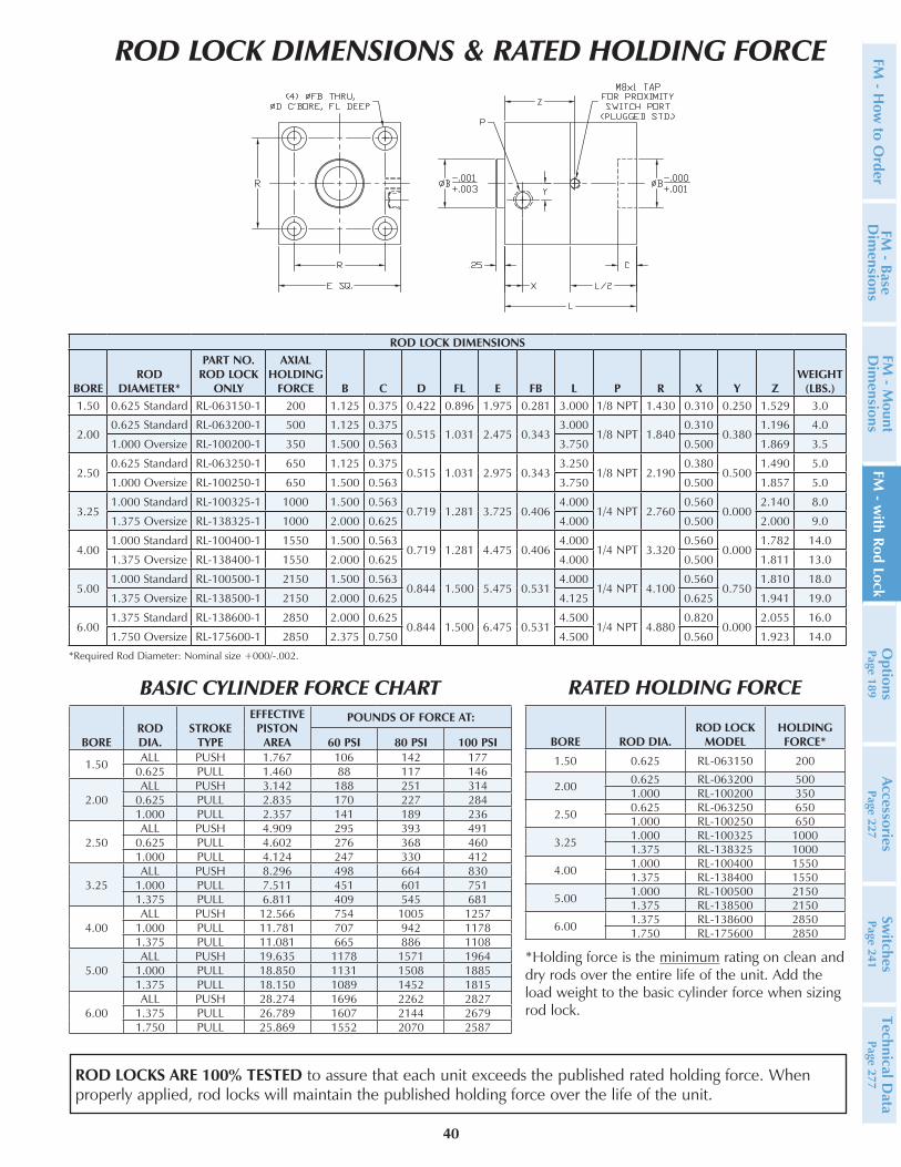
ROD LOCKS ARE 100% TESTED to assure that each unit exceeds the published rated holding force. When properly applied, rod locks will maintain the published holding force over the life of the unit.
FM - H
ow to O
rderFM
- Base D
imensions
FM - M
ount D
imensions
FM - w
ith Rod LockO
ptionsPage 189
AccessoriesPage 227
Switches
Page 241Technical D
ata Page 277
ROD LOCK DIMENSIONS & RATED HOLDING FORCE
BOREROD DIA.
STROKE TYPE
EFFECTIVE PISTON
AREA
POUNDS OF FORCE AT:
60 PSI 80 PSI 100 PSI
1.50 ALL PUSH 1.767 106 142 1770.625 PULL 1.460 88 117 146
2.00ALL PUSH 3.142 188 251 314
0.625 PULL 2.835 170 227 2841.000 PULL 2.357 141 189 236
2.50ALL PUSH 4.909 295 393 491
0.625 PULL 4.602 276 368 4601.000 PULL 4.124 247 330 412
3.25ALL PUSH 8.296 498 664 830
1.000 PULL 7.511 451 601 7511.375 PULL 6.811 409 545 681
4.00ALL PUSH 12.566 754 1005 1257
1.000 PULL 11.781 707 942 11781.375 PULL 11.081 665 886 1108
5.00ALL PUSH 19.635 1178 1571 1964
1.000 PULL 18.850 1131 1508 18851.375 PULL 18.150 1089 1452 1815
6.00ALL PUSH 28.274 1696 2262 2827
1.375 PULL 26.789 1607 2144 26791.750 PULL 25.869 1552 2070 2587
BORE ROD DIA.ROD LOCK
MODELHOLDINGFORCE*
1.50 0.625 RL-063150 200
2.00 0.625 RL-063200 5001.000 RL-100200 350
2.50 0.625 RL-063250 6501.000 RL-100250 650
3.25 1.000 RL-100325 10001.375 RL-138325 1000
4.00 1.000 RL-100400 15501.375 RL-138400 1550
5.00 1.000 RL-100500 21501.375 RL-138500 2150
6.00 1.375 RL-138600 28501.750 RL-175600 2850
*Holding force is the minimum rating on clean and dry rods over the entire life of the unit. Add the load weight to the basic cylinder force when sizing rod lock.
BASIC CYLINDER FORCE CHART RATED HOLDING FORCE
ROD LOCK DIMENSIONS
BOREROD
DIAMETER*
PART NO.ROD LOCK
ONLY
AXIAL HOLDING
FORCE B C D FL E FB L P R X Y ZWEIGHT
(LBS.)1.50 0.625 Standard RL-063150-1 200 1.125 0.375 0.422 0.896 1.975 0.281 3.000 1/8 NPT 1.430 0.310 0.250 1.529 3.0
2.000.625 Standard RL-063200-1 500 1.125 0.375
0.515 1.031 2.475 0.3433.000
1/8 NPT 1.8400.310
0.3801.196 4.0
1.000 Oversize RL-100200-1 350 1.500 0.563 3.750 0.500 1.869 3.5
2.500.625 Standard RL-063250-1 650 1.125 0.375
0.515 1.031 2.975 0.3433.250
1/8 NPT 2.1900.380
0.5001.490 5.0
1.000 Oversize RL-100250-1 650 1.500 0.563 3.750 0.500 1.857 5.0
3.251.000 Standard RL-100325-1 1000 1.500 0.563
0.719 1.281 3.725 0.4064.000
1/4 NPT 2.7600.560
0.0002.140 8.0
1.375 Oversize RL-138325-1 1000 2.000 0.625 4.000 0.500 2.000 9.0
4.001.000 Standard RL-100400-1 1550 1.500 0.563
0.719 1.281 4.475 0.4064.000
1/4 NPT 3.3200.560
0.0001.782 14.0
1.375 Oversize RL-138400-1 1550 2.000 0.625 4.000 0.500 1.811 13.0
5.001.000 Standard RL-100500-1 2150 1.500 0.563
0.844 1.500 5.475 0.5314.000
1/4 NPT 4.1000.560
0.7501.810 18.0
1.375 Oversize RL-138500-1 2150 2.000 0.625 4.125 0.625 1.941 19.0
6.001.375 Standard RL-138600-1 2850 2.000 0.625
0.844 1.500 6.475 0.5314.500
1/4 NPT 4.8800.820
0.0002.055 16.0
1.750 Oversize RL-175600-1 2850 2.375 0.750 4.500 0.560 1.923 14.0
*Required Rod Diameter: Nominal size +000/-.002.
41
CUSHIONS
H
HEAD CUSHION POSITION 2 IS STANDARD SPECIFY FOR POSITIONS:
1, 3 & 4
LH
LONG HEAD CUSHION POSITION 2 IS STANDARD SPECIFY FOR POSITIONS:
1, 3 & 4
ELH
EXTRA LONG HEAD CUSHION POSITION 2 IS STANDARD SPECIFY FOR POSITIONS:
1, 3 & 4X
C
CAP CUSHION POSITION 6 IS STANDARD SPECIFY FOR POSITIONS:
5, 7 & 8
LC
LONG CAP CUSHION POSITION 6 IS STANDARD SPECIFY FOR POSITIONS:
5, 7 & 8
ELC
EXTRA LONG CAP CUSHION POSITION 6 IS STANDARD SPECIFY FOR POSITIONS:
5, 7 & 8X
FIXED CUSHIONS
FCHFIXED HEAD CUSHION (NON-ADJUSTABLE, NO ADJUSTMENT NEEDLE)
FCCFIXED CAP CUSHION
(NON-ADJUSTABLE, NO ADJUSTMENT NEEDLE)
FCFIXED HEAD AND CAP
CUSHION (NON-ADJUSTABLE, NO ADJUSTMENT NEEDLE)
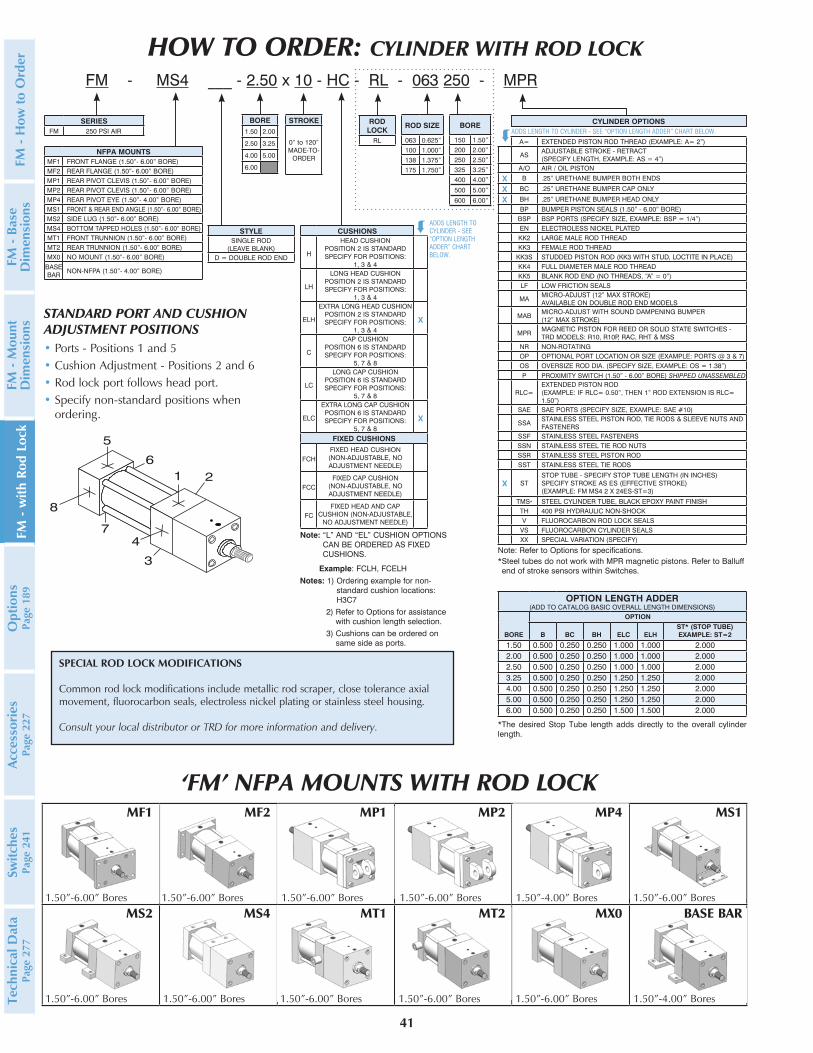
HOW TO ORDER: CYLINDER WITH ROD LOCK FM - MS4 ___ - 2.50 x 10 - HC - RL - 063 250 - MPR
SERIESFM 250 PSI AIR
NFPA MOUNTSMF1 FRONT FLANGE (1.50”- 6.00” BORE)MF2 REAR FLANGE (1.50”- 6.00” BORE)MP1 REAR PIVOT CLEVIS (1.50”- 6.00” BORE)MP2 REAR PIVOT CLEVIS (1.50”- 6.00” BORE)MP4 REAR PIVOT EYE (1.50”- 4.00” BORE)MS1 FRONT & REAR END ANGLE (1.50”- 6.00” BORE)MS2 SIDE LUG (1.50”- 6.00” BORE)MS4 BOTTOM TAPPED HOLES (1.50”- 6.00” BORE)MT1 FRONT TRUNNION (1.50”- 6.00” BORE)MT2 REAR TRUNNION (1.50”- 6.00” BORE)MX0 NO MOUNT (1.50”- 6.00” BORE)
BASE BAR
NON-NFPA (1.50”- 4.00” BORE)
BORE1.50 2.00
2.50 3.25
4.00 5.00
6.00
STYLESINGLE ROD
(LEAVE BLANK)D = DOUBLE ROD END
STROKE
0” to 120”MADE-TO-
ORDER
MF1
1.50”-6.00” Bores
MF2
1.50”-6.00” Bores
MP1
1.50”-6.00” Bores
MP2
1.50”-6.00” Bores
MP4
1.50”-4.00” Bores
MS1
1.50”-6.00” Bores
MS2
1.50”-6.00” Bores
MS4
1.50”-6.00” Bores
MT1
1.50”-6.00” Bores 1.50”-6.00” Bores
MX0
1.50”-6.00” Bores
BASE BAR
1.50”-4.00” Bores
‘FM’ NFPA MOUNTS WITH ROD LOCK
*The desired Stop Tube length adds directly to the overall cylinder length.
STANDARD PORT AND CUSHIONADJUSTMENT POSITIONS• Ports - Positions 1 and 5• Cushion Adjustment - Positions 2 and 6• Rod lock port follows head port.• Specify non-standard positions when
ordering.
Note: Refer to Options for specifications.* Steel tubes do not work with MPR magnetic pistons. Refer to Balluff end of stroke sensors within Switches.
Notes: 1) Ordering example for non-standard cushion locations: H3C7
2) Refer to Options for assistance with cushion length selection.
3) Cushions can be ordered on same side as ports.
ADDS LENGTH TO CYLINDER - SEE “OPTION LENGTH ADDER” CHART BELOW.
A= EXTENDED PISTON ROD THREAD (EXAMPLE: A= 2”)
ASADJUSTABLE STROKE - RETRACT (SPECIFY LENGTH, EXAMPLE: AS = 4”)
A/O AIR / OIL PISTON
X B .25” URETHANE BUMPER BOTH ENDS
X BC .25” URETHANE BUMPER CAP ONLY
X BH .25” URETHANE BUMPER HEAD ONLY
BP BUMPER PISTON SEALS (1.50” - 6.00” BORE)BSP BSP PORTS (SPECIFY SIZE, EXAMPLE: BSP = 1/4”)EN ELECTROLESS NICKEL PLATED KK2 LARGE MALE ROD THREADKK3 FEMALE ROD THREAD
KK3S STUDDED PISTON ROD (KK3 WITH STUD, LOCTITE IN PLACE)KK4 FULL DIAMETER MALE ROD THREADKK5 BLANK ROD END (NO THREADS, “A” = 0”)LF LOW FRICTION SEALS
MAMICRO-ADJUST (12” MAX STROKE) AVAILABLE ON DOUBLE ROD END MODELS
MABMICRO-ADJUST WITH SOUND DAMPENING BUMPER (12” MAX STROKE)
MPRMAGNETIC PISTON FOR REED OR SOLID STATE SWITCHES - TRD MODELS: R10, R10P, RAC, RHT & MSS
NR NON-ROTATING OP OPTIONAL PORT LOCATION OR SIZE (EXAMPLE: PORTS @ 3 & 7)OS OVERSIZE ROD DIA. (SPECIFY SIZE, EXAMPLE: OS = 1.38”)P PROXIMITY SWITCH (1.50” - 6.00” BORE) SHIPPED UNASSEMBLED
RLC=EXTENDED PISTON ROD (EXAMPLE: IF RLC= 0.50”, THEN 1” ROD EXTENSION IS RLC= 1.50”)
SAE SAE PORTS (SPECIFY SIZE, EXAMPLE: SAE #10)
SSASTAINLESS STEEL PISTON ROD, TIE RODS & SLEEVE NUTS AND FASTENERS
SSF STAINLESS STEEL FASTENERSSSN STAINLESS STEEL TIE ROD NUTSSSR STAINLESS STEEL PISTON ROD
SST STAINLESS STEEL TIE RODS
X STSTOP TUBE - SPECIFY STOP TUBE LENGTH (IN INCHES) SPECIFY STROKE AS ES (EFFECTIVE STROKE) (EXAMPLE: FM MS4 2 X 24ES-ST=3)
TMS* STEEL CYLINDER TUBE, BLACK EPOXY PAINT FINISHTH 400 PSI HYDRAULIC NON-SHOCK V FLUOROCARBON ROD LOCK SEALS
VS FLUOROCARBON CYLINDER SEALSXX SPECIAL VARIATION (SPECIFY)
CYLINDER OPTIONS
OPTION LENGTH ADDER(ADD TO CATALOG BASIC OVERALL LENGTH DIMENSIONS)
BORE
OPTION
B BC BH ELC ELHST* (STOP TUBE) EXAMPLE: ST=2
1.50 0.500 0.250 0.250 1.000 1.000 2.0002.00 0.500 0.250 0.250 1.000 1.000 2.0002.50 0.500 0.250 0.250 1.000 1.000 2.0003.25 0.500 0.250 0.250 1.250 1.250 2.0004.00 0.500 0.250 0.250 1.250 1.250 2.0005.00 0.500 0.250 0.250 1.250 1.250 2.0006.00 0.500 0.250 0.250 1.500 1.500 2.000
MT2
Note: “L” AND “EL” CUSHION OPTIONS CAN BE ORDERED AS FIXED CUSHIONS.
Example: FCLH, FCELH
BORE
150 1.50”200 2.00”250 2.50”325 3.25”400 4.00”
500 5.00”
600 6.00”
ROD SIZE
063 0.625”100 1.000”138 1.375”175 1.750”
ROD LOCK
RL
ADDS LENGTH TO CYLINDER - SEE “OPTION LENGTH ADDER” CHART BELOW.
SPECIAL ROD LOCK MODIFICATIONS
Common rod lock modifications include metallic rod scraper, close tolerance axial movement, fluorocarbon seals, electroless nickel plating or stainless steel housing.
Consult your local distributor or TRD for more information and delivery.
å
å
FM -
How
to
Ord
erFM
- B
ase
Dim
ensi
ons
FM -
Mou
nt
Dim
ensi
ons
FM -
with
Rod
Loc
kO
ptio
nsPa
ge 1
89Ac
cess
orie
sPa
ge 2
27Sw
itche
sPa
ge 2
41Te
chni
cal D
ata
Page
277
42
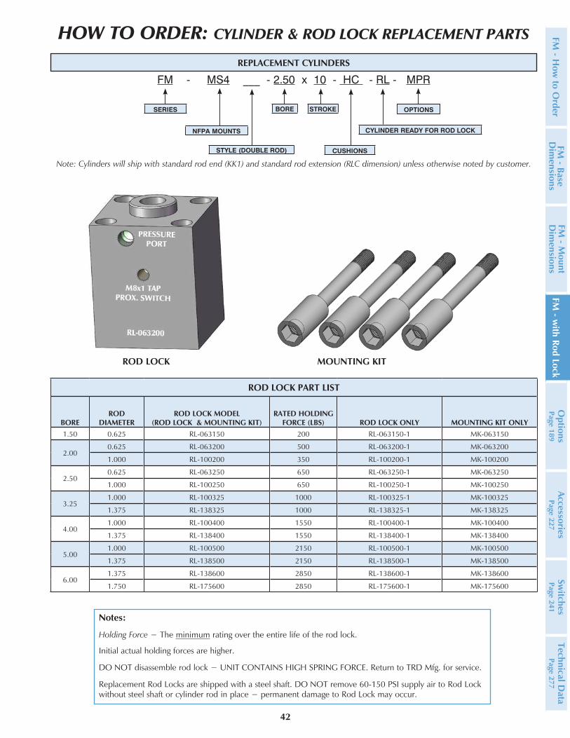
ROD LOCK PART LIST
BOREROD
DIAMETERROD LOCK MODEL
(ROD LOCK & MOUNTING KIT)RATED HOLDING
FORCE (LBS) ROD LOCK ONLY MOUNTING KIT ONLY1.50 0.625 RL-063150 200 RL-063150-1 MK-063150
2.000.625 RL-063200 500 RL-063200-1 MK-063200
1.000 RL-100200 350 RL-100200-1 MK-100200
2.500.625 RL-063250 650 RL-063250-1 MK-063250
1.000 RL-100250 650 RL-100250-1 MK-100250
3.251.000 RL-100325 1000 RL-100325-1 MK-100325
1.375 RL-138325 1000 RL-138325-1 MK-138325
4.001.000 RL-100400 1550 RL-100400-1 MK-100400
1.375 RL-138400 1550 RL-138400-1 MK-138400
5.001.000 RL-100500 2150 RL-100500-1 MK-100500
1.375 RL-138500 2150 RL-138500-1 MK-138500
6.001.375 RL-138600 2850 RL-138600-1 MK-138600
1.750 RL-175600 2850 RL-175600-1 MK-175600
Notes:
Holding Force − The minimum rating over the entire life of the rod lock.
Initial actual holding forces are higher.
DO NOT disassemble rod lock − UNIT CONTAINS HIGH SPRING FORCE. Return to TRD Mfg. for service.
Replacement Rod Locks are shipped with a steel shaft. DO NOT remove 60-150 PSI supply air to Rod Lock without steel shaft or cylinder rod in place − permanent damage to Rod Lock may occur.
FM - MS4 ___ - 2.50 x 10 - HC - RL - MPR
SERIES
NFPA MOUNTS
BORE
STYLE (DOUBLE ROD)
OPTIONSSTROKE
HOW TO ORDER: CYLINDER & ROD LOCK REPLACEMENT PARTS
REPLACEMENT CYLINDERS
CYLINDER READY FOR ROD LOCK
CUSHIONS
Note: Cylinders will ship with standard rod end (KK1) and standard rod extension (RLC dimension) unless otherwise noted by customer.
FM - H
ow to O
rderFM
- Base D
imensions
FM - M
ount D
imensions
FM - w
ith Rod LockO
ptionsPage 189
AccessoriesPage 227
Switches
Page 241Technical D
ata Page 277
MOUNTING KITROD LOCK

43
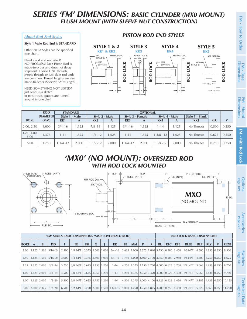
SERIES ‘FM’ DIMENSIONS: BASIC CYLINDER (MX0 MOUNT)FLUSH MOUNT (WITH SLEEVE NUT CONSTRUCTION)
About Rod End Styles
Style 1 Male Rod End is STANDARD
Other NFPA Styles can be specified (see chart).
Need a rod end not listed? NO PROBLEM! Each Piston Rod is made-to-order and does not delay shipment. Coarse UNC threads, Metric threads or just plain rod ends are common. Thread lengths are also made-to-order (Specify: “A”=Length).
NEED SOMETHING NOT LISTED? Just send us a sketch. In most cases, quotes are turned around in one day!
PISTON ROD END STYLES
RLC RLC RLC
STYLE 1 & 2 KK1 & KK2
STYLE 3 KK3
STYLE 4 KK4
BORE
ROD DIAMETER
(MM)
STANDARD OPTIONAL
RLC VStyle 1 - Male Style 2 - Male Style 3 - Female Style 4 - Male Style 5 - Blank
KK1 A KK2 A KK3 A KK4 A KK51.50, 2.00,
2.50 0.625 7/16 -20 0.750 1/2 -20 0.750 7/16 -20 0.750 5/8 -18 0.750 No Threads 0.375 0.250
3.25, 4.00, 5.00 1.000 3/4 -16 1.125 7/8 -14 1.125 3/4 -16 1.125 1 -14 1.125 No Threads 0.500 0.250
6.00 1.375 1-14 1.625 1 1/4 -12 1.625 1-14 1.625 1 3/8 -12 1.625 No Threads 0.625 0.250
‘FM’ SERIES BASIC DIMENSIONS ‘MX0’ (STANDARD ROD) ROD LOCK BASIC DIMENSIONS
BORE A B DD E EE G J KK LB MM P R RL RLC RLE RLEE RLP RLY V RLZB
1.50 0.750 1.125 1/4 -28 2.000 1/4 NPT 1.500 1.000 7/16 -20 3.625 0.625 2.375 1.430 3.000 0.375 1.980 1/8 NPT 3.563 0.940 0.250 7.250
2.00 0.750 1.125 5/16 -24 2.500 1/4 NPT 1.500 1.000 7/16 -20 3.625 0.625 2.375 1.840 3.000 0.375 2.480 1/8 NPT 3.563 0.940 0.250 7.250
2.50 0.750 1.125 5/16 -24 3.000 1/4 NPT 1.500 1.000 7/16 -20 3.750 0.625 2.500 2.190 3.250 0.375 2.980 1/8 NPT 3.750 1.000 0.250 7.625
3.25 1.125 1.500 3/8 -24 3.750 3/8 NPT 1.750 1.250 3/4 -16 4.250 1.000 2.750 2.760 4.000 0.500 3.730 1/4 NPT 4.438 1.313 0.250 9.000
4.00 1.125 1.500 3/8 -24 4.500 3/8 NPT 1.750 1.250 3/4 -16 4.250 1.000 2.750 3.320 4.000 0.500 4.480 1/4 NPT 4.438 1.313 0.250 9.000
5.00 1.125 1.500 1/2 -20 5.500 3/8 NPT 1.750 1.250 3/4 -16 4.500 1.000 3.000 4.100 4.000 0.500 5.480 1/4 NPT 4.438 1.313 0.250 9.250
6.00 1.625 2.000 1/2 -20 6.500 1/2 NPT 2.000 1.500 1-14 5.000 1.375 3.250 4.880 4.500 0.625 6.480 1/4 NPT 5.060 1.440 0.250 10.375
E SQ.
RLEE (NPT)
RLE SQ.
RLY RLPRLEE (NPT)
RL
RLC
(BOTH ENDS)
RLZB + STROKE
STYLE 5 KK5
RLC
STANDARD ROD: ‘MX0’ (NO MOUNT)WITH ROD LOCK MOUNTED
ROD
LO
CK
ROD
LO
CK
ROD
LO
CK
ROD
LO
CK
FM -
How
to
Ord
erFM
- B
ase
Dim
ensi
ons
FM -
Mou
nt
Dim
ensi
ons
FM -
with
Rod
Loc
kO
ptio
nsPa
ge 1
89Ac
cess
orie
sPa
ge 2
27Sw
itche
sPa
ge 2
41Te
chni
cal D
ata
Page
277
44
SERIES ‘FM’ DIMENSIONS: BASIC CYLINDER (MX0 MOUNT)FLUSH MOUNT (WITH SLEEVE NUT CONSTRUCTION)
About Rod End Styles
Style 1 Male Rod End is STANDARD
Other NFPA Styles can be specified (see chart).
Need a rod end not listed? NO PROBLEM! Each Piston Rod is made-to-order and does not delay shipment. Coarse UNC threads, Metric threads or just plain rod ends are common. Thread lengths are also made-to-order (Specify: “A”=Length).
NEED SOMETHING NOT LISTED? Just send us a sketch. In most cases, quotes are turned around in one day!
PISTON ROD END STYLES
RLC RLC RLC
STYLE 1 & 2 KK1 & KK2
STYLE 3 KK3
STYLE 4 KK4
BORE
ROD DIAMETER
(MM)
STANDARD OPTIONAL
RLC VStyle 1 - Male Style 2 - Male Style 3 - Female Style 4 - Male Style 5 - Blank
KK1 A KK2 A KK3 A KK4 A KK5
2.00, 2.50 1.000 3/4 -16 1.125 7/8 -14 1.125 3/4 -16 1.125 1 -14 1.125 No Threads 0.500 0.250
3.25, 4.00, 5.00 1.375 1 -14 1.625 1 1/4 -12 1.625 1 -14 1.625 1 3/8 -12 1.625 No Threads 0.625 0.250
6.00 1.750 1 1/4 -12 2.000 1 1/2 -12 2.000 1 1/4 -12 2.000 1 3/4 -12 2.000 No Threads 0.750 0.250
‘FM’ SERIES BASIC DIMENSIONS ‘MX0’ (OVERSIZED ROD) ROD LOCK BASIC DIMENSIONS
BORE A B DD E EE FH G J KK LB MM P R RL RLC RLE RLEE RLP RLY V RLZB
2.00 1.125 1.500 5/16 -24 2.500 1/4 NPT 0.375 1.500 1.000 3/4 -16 3.625 1.000 2.375 1.840 3.750 0.500 2.480 1/8 NPT 4.500 1.250 0.250 8.500
2.50 1.125 1.500 5/16 -24 3.000 1/4 NPT 0.375 1.500 1.000 3/4 -16 3.750 1.000 2.500 2.190 3.750 0.500 2.980 1/8 NPT 4.500 1.250 0.250 8.625
3.25 1.625 2.000 3/8 -24 3.750 3/8 NPT 0.625 1.750 1.250 1-14 4.250 1.375 2.750 2.760 4.000 0.625 3.730 1/4 NPT 5.063 1.438 0.250 9.750
4.00 1.625 2.000 3/8 -24 4.500 3/8 NPT 0.625 1.750 1.250 1-14 4.250 1.375 2.750 3.320 4.000 0.625 4.480 1/4 NPT 5.063 1.438 0.250 9.750
5.00 1.625 2.000 1/2 -20 5.500 3/8 NPT 0.625 1.750 1.250 1-14 4.500 1.375 3.000 4.100 4.125 0.625 5.480 1/4 NPT 5.188 1.438 0.250 10.125
6.00 2.000 2.375 1/2 -20 6.500 1/2 NPT 0.750 2.000 1.500 1 1/4 -12 5.000 1.750 3.250 4.875 4.500 0.750 6.480 1/4 NPT 5.820 1.563 0.250 11.250
RL
RLEE (NPT)RLY RLP
RLE SQ.
E SQ.
FH
RLC
V
EE (NPT) EE (NPT)RLEE (NPT)
(BOTH ENDS)
RLZB + STROKE
STYLE 5 KK5
RLC
‘MX0’ (NO MOUNT): OVERSIZED ROD WITH ROD LOCK MOUNTED
ROD
LO
CK
ROD
LO
CK
ROD
LO
CK
ROD
LO
CK
FM - H
ow to O
rderFM
- Base D
imensions
FM - M
ount D
imensions
FM - w
ith Rod LockO
ptionsPage 189
AccessoriesPage 227
Switches
Page 241Technical D
ata Page 277
45
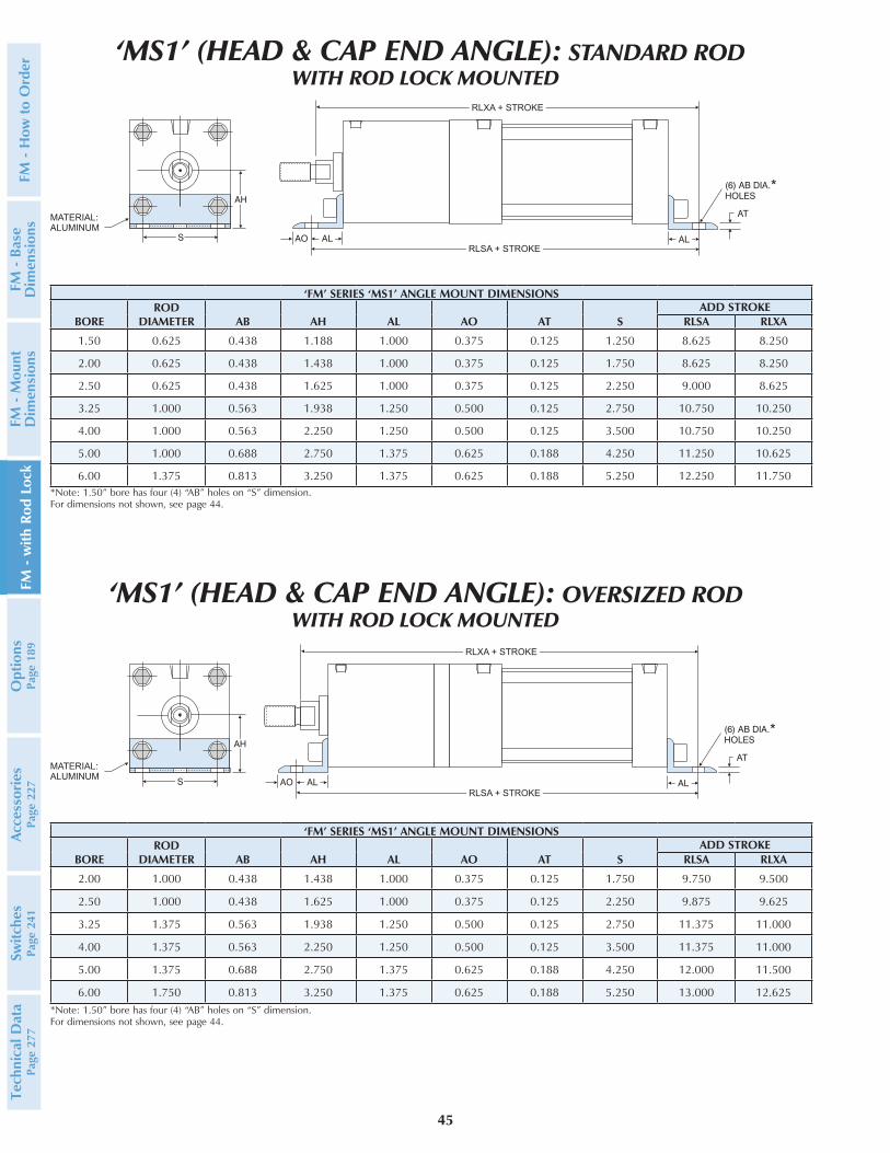
MATERIAL:ALUMINUM
RLXA + STROKE
RLSA + STROKE
RLXA + STROKE
RLSA + STROKE
MATERIAL:ALUMINUM
‘FM’ SERIES ‘MS1’ ANGLE MOUNT DIMENSIONS
BOREROD
DIAMETER AB AH AL AO AT SADD STROKE
RLSA RLXA
1.50 0.625 0.438 1.188 1.000 0.375 0.125 1.250 8.625 8.250
2.00 0.625 0.438 1.438 1.000 0.375 0.125 1.750 8.625 8.250
2.50 0.625 0.438 1.625 1.000 0.375 0.125 2.250 9.000 8.625
3.25 1.000 0.563 1.938 1.250 0.500 0.125 2.750 10.750 10.250
4.00 1.000 0.563 2.250 1.250 0.500 0.125 3.500 10.750 10.250
5.00 1.000 0.688 2.750 1.375 0.625 0.188 4.250 11.250 10.625
6.00 1.375 0.813 3.250 1.375 0.625 0.188 5.250 12.250 11.750*Note: 1.50” bore has four (4) “AB” holes on “S” dimension.For dimensions not shown, see page 44.
‘FM’ SERIES ‘MS1’ ANGLE MOUNT DIMENSIONS
BOREROD
DIAMETER AB AH AL AO AT SADD STROKE
RLSA RLXA
2.00 1.000 0.438 1.438 1.000 0.375 0.125 1.750 9.750 9.500
2.50 1.000 0.438 1.625 1.000 0.375 0.125 2.250 9.875 9.625
3.25 1.375 0.563 1.938 1.250 0.500 0.125 2.750 11.375 11.000
4.00 1.375 0.563 2.250 1.250 0.500 0.125 3.500 11.375 11.000
5.00 1.375 0.688 2.750 1.375 0.625 0.188 4.250 12.000 11.500
6.00 1.750 0.813 3.250 1.375 0.625 0.188 5.250 13.000 12.625*Note: 1.50” bore has four (4) “AB” holes on “S” dimension.For dimensions not shown, see page 44.
‘MS1’ (HEAD & CAP END ANGLE): STANDARD RODWITH ROD LOCK MOUNTED
‘MS1’ (HEAD & CAP END ANGLE): OVERSIZED ROD WITH ROD LOCK MOUNTED
FM -
How
to
Ord
erFM
- B
ase
Dim
ensi
ons
FM -
Mou
nt
Dim
ensi
ons
FM -
with
Rod
Loc
kO
ptio
nsPa
ge 1
89Ac
cess
orie
sPa
ge 2
27Sw
itche
sPa
ge 2
41Te
chni
cal D
ata
Page
277
46
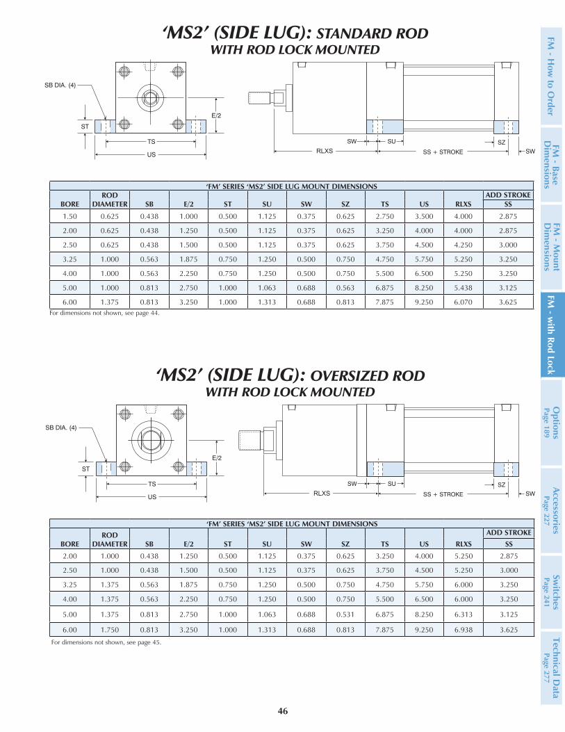
RLXS
For dimensions not shown, see page 44.
‘FM’ SERIES ‘MS2’ SIDE LUG MOUNT DIMENSIONS
BOREROD
DIAMETER SB E/2 ST SU SW SZ TS US RLXSADD STROKE
SS
1.50 0.625 0.438 1.000 0.500 1.125 0.375 0.625 2.750 3.500 4.000 2.875
2.00 0.625 0.438 1.250 0.500 1.125 0.375 0.625 3.250 4.000 4.000 2.875
2.50 0.625 0.438 1.500 0.500 1.125 0.375 0.625 3.750 4.500 4.250 3.000
3.25 1.000 0.563 1.875 0.750 1.250 0.500 0.750 4.750 5.750 5.250 3.250
4.00 1.000 0.563 2.250 0.750 1.250 0.500 0.750 5.500 6.500 5.250 3.250
5.00 1.000 0.813 2.750 1.000 1.063 0.688 0.563 6.875 8.250 5.438 3.125
6.00 1.375 0.813 3.250 1.000 1.313 0.688 0.813 7.875 9.250 6.070 3.625
RLXS
For dimensions not shown, see page 45.
‘FM’ SERIES ‘MS2’ SIDE LUG MOUNT DIMENSIONS
BOREROD
DIAMETER SB E/2 ST SU SW SZ TS US RLXS
ADD STROKE
SS
2.00 1.000 0.438 1.250 0.500 1.125 0.375 0.625 3.250 4.000 5.250 2.875
2.50 1.000 0.438 1.500 0.500 1.125 0.375 0.625 3.750 4.500 5.250 3.000
3.25 1.375 0.563 1.875 0.750 1.250 0.500 0.750 4.750 5.750 6.000 3.250
4.00 1.375 0.563 2.250 0.750 1.250 0.500 0.750 5.500 6.500 6.000 3.250
5.00 1.375 0.813 2.750 1.000 1.063 0.688 0.531 6.875 8.250 6.313 3.125
6.00 1.750 0.813 3.250 1.000 1.313 0.688 0.813 7.875 9.250 6.938 3.625
‘MS2’ (SIDE LUG): STANDARD ROD WITH ROD LOCK MOUNTED
‘MS2’ (SIDE LUG): OVERSIZED ROD WITH ROD LOCK MOUNTED
FM - H
ow to O
rderFM
- Base D
imensions
FM - M
ount D
imensions
FM - w
ith Rod LockO
ptionsPage 189
AccessoriesPage 227
Switches
Page 241Technical D
ata Page 277

47
E SQ.
SNRLXT
RLE SQ.
RLEE NPTRLEE NPT
RLPRLY
RLC
RLZB + STROKE
(BOTH ENDS)
RLE SQ.
E SQ.
SN
RLEE NPTRLPRLEE NPT RLY
RLC
(BOTH ENDS)
RLZB + STROKE
RLXT
‘FM’ SERIES ‘MS4’ FLUSH MOUNT DIMENSIONS ROD LOCK BASIC DIMENSIONS
BORE A B DD E EE KK MM NT P R SN TK TN RLC RLE RLEE RLP RLXT RLY RLZB V
1.50 0.750 1.125 1/4 -28 2.000 1/4 NPT 7/16-20 0.625 1/4 -20 2.375 1.438 2.250 0.375 0.625 0.375 1.984 1/8
NPT 3.563 4.570 0.938 7.250 0.250
2.00 0.750 1.125 5/16 -24 2.500 1/4 NPT 7/16-20 0.625 5/16 -18 2.375 1.844 2.250 0.500 0.875 0.375 2.484 1/8
NPT 3.563 4.570 0.938 7.250 0.250
2.50 0.750 1.125 5/16 -24 3.000 1/4 NPT 7/16-20 0.625 3/4 -16 2.500 2.188 2.375 0.625 1.250 0.375 2.984 1/8
NPT 3.750 4.820 1.000 7.625 0.250
3.25 1.125 1.500 3/8 -24 3.750 3/8 NPT 3/4 -16 1.000 1/2 -13 2.750 2.760 2.625 0.750 1.500 0.500 3.734 1/4
NPT 4.438 5.820 1.313 9.000 0.250
4.00 1.125 1.500 3/8 -24 4.500 3/8 NPT 3/4 -16 1.000 1/2 -13 2.750 3.320 2.625 0.750 2.063 0.500 4.484 1/4
NPT 4.438 5.820 1.313 9.000 0.250
5.00 1.125 1.500 1/2 -20 5.500 3/8 NPT 3/4 -16 1.000 5/8 -11 3.000 4.100 2.875 1.000 2.688 0.500 5.484 1/4
NPT 4.438 5.820 1.313 9.250 0.250
6.00 1.625 2.000 1/2 -20 6.500 1/2 NPT 1-14 1.375 3/4 -10 3.250 4.875 3.125 1.125 3.250 0.625 6.484 1/4
NPT 5.063 6.560 1.438 10.375 0.250
‘FM’ SERIES OVERSIZE ROD ‘MS4’ FLUSH MOUNT DIMENSIONS ROD LOCK BASIC DIMENSIONS
BORE A B DD E EE KK MM NT P R SN TK TN RLC RLE RLEE RLP RLXT RLY RLZB V
2.00 1.125 1.500 5/16 -24 2.500 1/4 NPT 3/4 -16 1.000 0.313-18 2.375 1.844 2.250 0.500 0.875 0.500 2.484 1/8
NPT 4.500 5.813 1.250 8.500 0.250
2.50 1.125 1.500 5/16 -24 3.000 1/4 NPT 3/4 -16 1.000 0.375-16 2.500 2.188 2.375 0.625 1.250 0.500 2.984 1/8
NPT 4.500 5.813 1.250 8.625 0.250
3.25 1.625 2.000 3/8 -24 3.750 3/8 NPT 1-14 1.375 0.500-13 2.750 2.760 2.625 0.750 1.500 0.625 3.734 1/4
NPT 5.063 6.570 1.438 9.750 0.250
4.00 1.625 2.000 3/8 -24 4.500 3/8 NPT 1-14 1.375 0.500-13 2.750 3.320 2.625 0.750 2.063 0.625 4.484 1/4
NPT 5.063 6.570 1.438 9.750 0.250
5.00 1.625 2.000 1/2 -20 5.500 3/8 NPT 1-14 1.375 0.636-11 3.000 4.100 2.875 1.000 2.688 0.625 5.484 1/4
NPT 5.188 6.688 1.438 10.125 0.250
6.00 2.000 2.375 1/2 -20 6.500 1/2 NPT 1 1/4-12 1.750 0.750-10 3.250 4.875 3.125 1.125 3.250 0.750 6.484 1/4
NPT 5.820 7.438 1.563 11.250 0.250
For dimensions not shown, see page 44.
‘MS4’ (BOTTOM TAPPED HOLES): OVERSIZED ROD WITH ROD LOCK MOUNTED
‘MS4’ (BOTTOM TAPPED HOLES): STANDARD ROD WITH ROD LOCK MOUNTED
For dimensions not shown, see page 45.
FM -
How
to
Ord
erFM
- B
ase
Dim
ensi
ons
FM -
Mou
nt
Dim
ensi
ons
FM -
with
Rod
Loc
kO
ptio
nsPa
ge 1
89Ac
cess
orie
sPa
ge 2
27Sw
itche
sPa
ge 2
41Te
chni
cal D
ata
Page
277
48
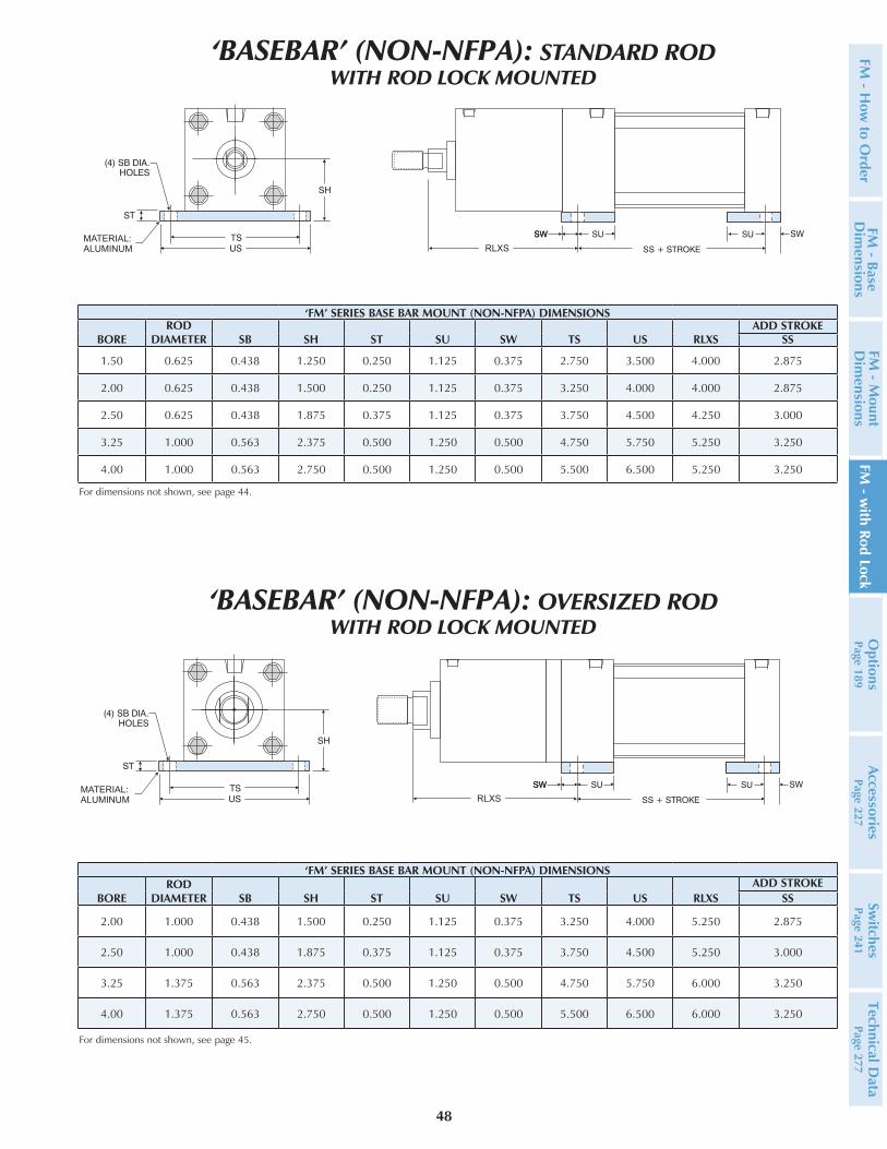
MATERIAL:ALUMINUM RLXS
For dimensions not shown, see page 45.
MATERIAL:ALUMINUM RLXS
‘FM’ SERIES BASE BAR MOUNT (NON-NFPA) DIMENSIONS
BOREROD
DIAMETER SB SH ST SU SW TS US RLXSADD STROKE
SS
1.50 0.625 0.438 1.250 0.250 1.125 0.375 2.750 3.500 4.000 2.875
2.00 0.625 0.438 1.500 0.250 1.125 0.375 3.250 4.000 4.000 2.875
2.50 0.625 0.438 1.875 0.375 1.125 0.375 3.750 4.500 4.250 3.000
3.25 1.000 0.563 2.375 0.500 1.250 0.500 4.750 5.750 5.250 3.250
4.00 1.000 0.563 2.750 0.500 1.250 0.500 5.500 6.500 5.250 3.250
For dimensions not shown, see page 44.
‘FM’ SERIES BASE BAR MOUNT (NON-NFPA) DIMENSIONS
BOREROD
DIAMETER SB SH ST SU SW TS US RLXSADD STROKE
SS
2.00 1.000 0.438 1.500 0.250 1.125 0.375 3.250 4.000 5.250 2.875
2.50 1.000 0.438 1.875 0.375 1.125 0.375 3.750 4.500 5.250 3.000
3.25 1.375 0.563 2.375 0.500 1.250 0.500 4.750 5.750 6.000 3.250
4.00 1.375 0.563 2.750 0.500 1.250 0.500 5.500 6.500 6.000 3.250
‘BASEBAR’ (NON-NFPA): OVERSIZED ROD WITH ROD LOCK MOUNTED
‘BASEBAR’ (NON-NFPA): STANDARD ROD WITH ROD LOCK MOUNTED
FM - H
ow to O
rderFM
- Base D
imensions
FM - M
ount D
imensions
FM - w
ith Rod LockO
ptionsPage 189
AccessoriesPage 227
Switches
Page 241Technical D
ata Page 277
49
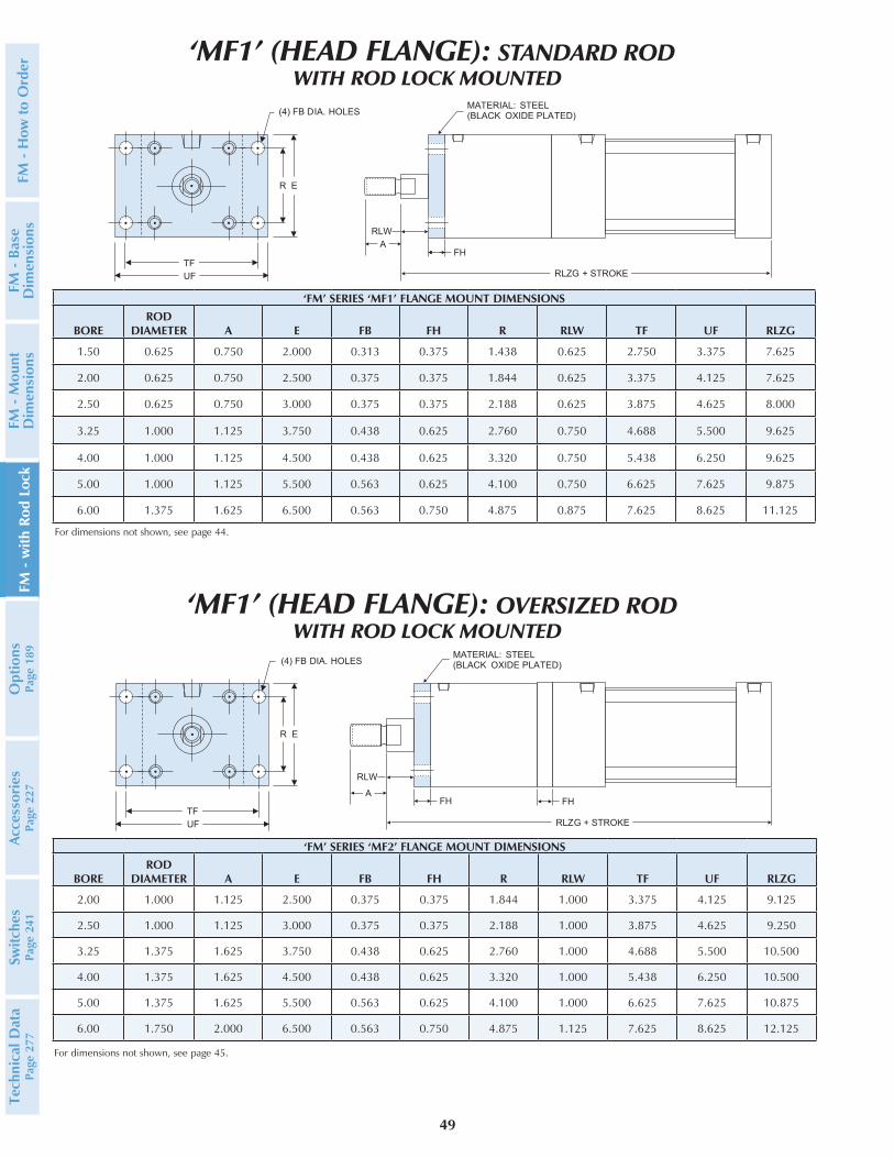
‘FM’ SERIES ‘MF1’ FLANGE MOUNT DIMENSIONS
BOREROD
DIAMETER A E FB FH R RLW TF UF RLZG
1.50 0.625 0.750 2.000 0.313 0.375 1.438 0.625 2.750 3.375 7.625
2.00 0.625 0.750 2.500 0.375 0.375 1.844 0.625 3.375 4.125 7.625
2.50 0.625 0.750 3.000 0.375 0.375 2.188 0.625 3.875 4.625 8.000
3.25 1.000 1.125 3.750 0.438 0.625 2.760 0.750 4.688 5.500 9.625
4.00 1.000 1.125 4.500 0.438 0.625 3.320 0.750 5.438 6.250 9.625
5.00 1.000 1.125 5.500 0.563 0.625 4.100 0.750 6.625 7.625 9.875
6.00 1.375 1.625 6.500 0.563 0.750 4.875 0.875 7.625 8.625 11.125
For dimensions not shown, see page 44.
For dimensions not shown, see page 45.
RLW
AFH
R E
TFUF
(4) FB DIA. HOLESMATERIAL: STEEL(BLACK OXIDE PLATED)
FH
RLZG + STROKE
(4) FB DIA. HOLES
TFUF
R E
RLWA
FH
MATERIAL: STEEL(BLACK OXIDE PLATED)
RLZG + STROKE
‘FM’ SERIES ‘MF2’ FLANGE MOUNT DIMENSIONS
BOREROD
DIAMETER A E FB FH R RLW TF UF RLZG
2.00 1.000 1.125 2.500 0.375 0.375 1.844 1.000 3.375 4.125 9.125
2.50 1.000 1.125 3.000 0.375 0.375 2.188 1.000 3.875 4.625 9.250
3.25 1.375 1.625 3.750 0.438 0.625 2.760 1.000 4.688 5.500 10.500
4.00 1.375 1.625 4.500 0.438 0.625 3.320 1.000 5.438 6.250 10.500
5.00 1.375 1.625 5.500 0.563 0.625 4.100 1.000 6.625 7.625 10.875
6.00 1.750 2.000 6.500 0.563 0.750 4.875 1.125 7.625 8.625 12.125
‘MF1’ (HEAD FLANGE): OVERSIZED RODWITH ROD LOCK MOUNTED
‘MF1’ (HEAD FLANGE): STANDARD RODWITH ROD LOCK MOUNTED
FM -
How
to
Ord
erFM
- B
ase
Dim
ensi
ons
FM -
Mou
nt
Dim
ensi
ons
FM -
with
Rod
Loc
kO
ptio
nsPa
ge 1
89Ac
cess
orie
sPa
ge 2
27Sw
itche
sPa
ge 2
41Te
chni
cal D
ata
Page
277
50
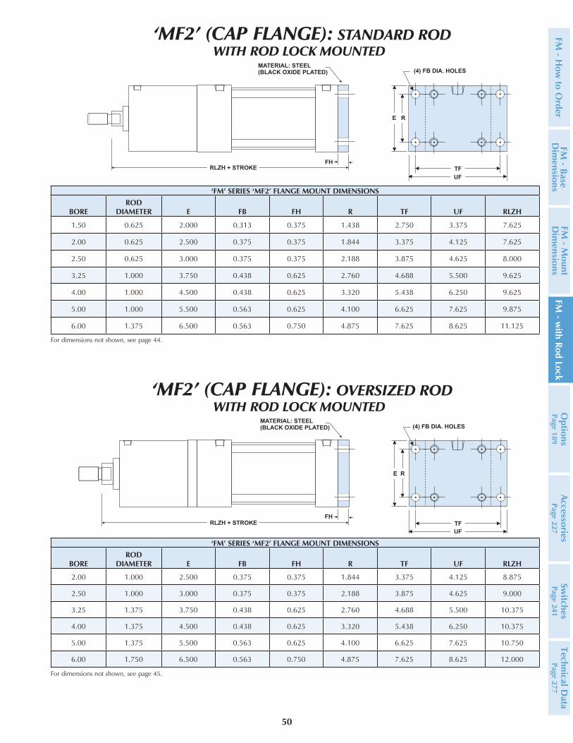
‘FM’ SERIES ‘MF2’ FLANGE MOUNT DIMENSIONS
BOREROD
DIAMETER E FB FH R TF UF RLZH
1.50 0.625 2.000 0.313 0.375 1.438 2.750 3.375 7.625
2.00 0.625 2.500 0.375 0.375 1.844 3.375 4.125 7.625
2.50 0.625 3.000 0.375 0.375 2.188 3.875 4.625 8.000
3.25 1.000 3.750 0.438 0.625 2.760 4.688 5.500 9.625
4.00 1.000 4.500 0.438 0.625 3.320 5.438 6.250 9.625
5.00 1.000 5.500 0.563 0.625 4.100 6.625 7.625 9.875
6.00 1.375 6.500 0.563 0.750 4.875 7.625 8.625 11.125
For dimensions not shown, see page 44.
MATERIAL: STEEL(BLACK OXIDE PLATED)
FHTFUF
E R
(4) FB DIA. HOLES
RLZH + STROKE
MATERIAL: STEEL(BLACK OXIDE PLATED)
FH
(4) FB DIA. HOLES
E R
TF
UF
RLZH + STROKE
‘FM’ SERIES ‘MF2’ FLANGE MOUNT DIMENSIONS
BOREROD
DIAMETER E FB FH R TF UF RLZH
2.00 1.000 2.500 0.375 0.375 1.844 3.375 4.125 8.875
2.50 1.000 3.000 0.375 0.375 2.188 3.875 4.625 9.000
3.25 1.375 3.750 0.438 0.625 2.760 4.688 5.500 10.375
4.00 1.375 4.500 0.438 0.625 3.320 5.438 6.250 10.375
5.00 1.375 5.500 0.563 0.625 4.100 6.625 7.625 10.750
6.00 1.750 6.500 0.563 0.750 4.875 7.625 8.625 12.000
For dimensions not shown, see page 45.
‘MF2’ (CAP FLANGE): OVERSIZED RODWITH ROD LOCK MOUNTED
‘MF2’ (CAP FLANGE): STANDARD RODWITH ROD LOCK MOUNTED
FM - H
ow to O
rderFM
- Base D
imensions
FM - M
ount D
imensions
FM - w
ith Rod LockO
ptionsPage 189
AccessoriesPage 227
Switches
Page 241Technical D
ata Page 277

51
‘FM’ SERIES ‘MT1’ HEAD TRUNNION AND ‘MT2’ CAP TRUNNION MOUNT DIMENSIONS
BOREROD
DIAMETER E RLE TD TL UT RLXG
1.50 0.625 2.000 1.984 1.000 1.000 4.000 4.375
2.00 0.625 2.500 2.484 1.000 1.000 4.500 4.375
2.50 0.625 3.000 2.984 1.000 1.000 5.000 4.625
3.25 1.000 3.750 3.734 1.000 1.000 5.750 5.625
4.00 1.000 4.500 4.484 1.000 1.000 6.500 5.625
5.00 1.000 5.500 5.484 1.000 1.000 7.500 5.625
6.00 1.375 6.500 6.484 1.375 1.375 9.250 6.375
For dimensions not shown, see page 44.
‘FM’ SERIES ‘MT1’ HEAD TRUNNION AND ‘MT2’ CAP TRUNNION MOUNT DIMENSIONS
BOREROD
DIAMETER E RLE TD TL UT RLXG
2.00 1.000 2.500 2.484 1.000 1.000 4.500 5.625
2.50 1.000 3.000 2.984 1.000 1.000 5.000 5.625
3.25 1.375 3.750 3.734 1.000 1.000 5.750 6.375
4.00 1.375 4.500 4.484 1.000 1.000 6.500 6.375
5.00 1.375 5.500 5.484 1.000 1.000 7.500 6.500
6.00 1.750 6.500 6.484 1.375 1.375 9.250 7.250
(ROD LOCK)RLE SQ.
(CYLINDER)E SQ.
RLXG
(ROD LOCK)RLE SQ.
(CYLINDER)E SQ.
RLXG
Note: MT1 standard cushion locations at 3 and 6
‘MT1’ (HEAD TRUNNION): OVERSIZED RODWITH ROD LOCK MOUNTED
‘MT1’ (HEAD TRUNNION): STANDARD RODWITH ROD LOCK MOUNTED
Note: MT1 Trunnions are bolt on, non-removable design.
For dimensions not shown, see page 45.
Note: MT1 standard cushion locations at 3 and 6
Note: MT1 Trunnions are bolt on, non-removable design.
FM -
How
to
Ord
erFM
- B
ase
Dim
ensi
ons
FM -
Mou
nt
Dim
ensi
ons
FM -
with
Rod
Loc
kO
ptio
nsPa
ge 1
89Ac
cess
orie
sPa
ge 2
27Sw
itche
sPa
ge 2
41Te
chni
cal D
ata
Page
277
52
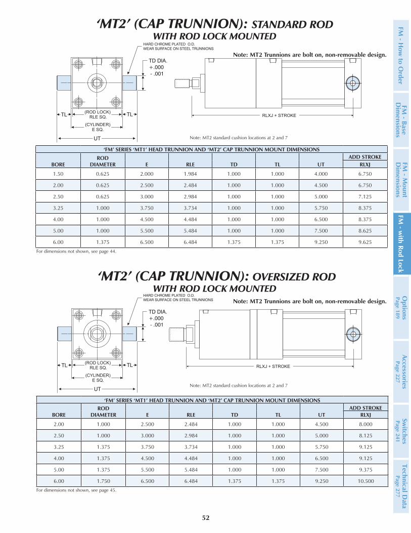
‘FM’ SERIES ‘MT1’ HEAD TRUNNION AND ‘MT2’ CAP TRUNNION MOUNT DIMENSIONS
BOREROD
DIAMETER E RLE TD TL UTADD STROKE
RLXJ
1.50 0.625 2.000 1.984 1.000 1.000 4.000 6.750
2.00 0.625 2.500 2.484 1.000 1.000 4.500 6.750
2.50 0.625 3.000 2.984 1.000 1.000 5.000 7.125
3.25 1.000 3.750 3.734 1.000 1.000 5.750 8.375
4.00 1.000 4.500 4.484 1.000 1.000 6.500 8.375
5.00 1.000 5.500 5.484 1.000 1.000 7.500 8.625
6.00 1.375 6.500 6.484 1.375 1.375 9.250 9.625
For dimensions not shown, see page 44.
‘FM’ SERIES ‘MT1’ HEAD TRUNNION AND ‘MT2’ CAP TRUNNION MOUNT DIMENSIONS
BOREROD
DIAMETER E RLE TD TL UTADD STROKE
RLXJ
2.00 1.000 2.500 2.484 1.000 1.000 4.500 8.000
2.50 1.000 3.000 2.984 1.000 1.000 5.000 8.125
3.25 1.375 3.750 3.734 1.000 1.000 5.750 9.125
4.00 1.375 4.500 4.484 1.000 1.000 6.500 9.125
5.00 1.375 5.500 5.484 1.000 1.000 7.500 9.375
6.00 1.750 6.500 6.484 1.375 1.375 9.250 10.500
(ROD LOCK)RLE SQ.
(CYLINDER)E SQ.
RLXJ + STROKE
(ROD LOCK)RLE SQ.
(CYLINDER)E SQ.
RLXJ + STROKE
Note: MT2 standard cushion locations at 2 and 7
‘MT2’ (CAP TRUNNION): OVERSIZED RODWITH ROD LOCK MOUNTED
‘MT2’ (CAP TRUNNION): STANDARD ROD WITH ROD LOCK MOUNTED
Note: MT2 Trunnions are bolt on, non-removable design.
For dimensions not shown, see page 45.
Note: MT2 standard cushion locations at 2 and 7
Note: MT2 Trunnions are bolt on, non-removable design.
FM - H
ow to O
rderFM
- Base D
imensions
FM - M
ount D
imensions
FM - w
ith Rod LockO
ptionsPage 189
AccessoriesPage 227
Switches
Page 241Technical D
ata Page 277

53
‘FM’ SERIES ‘MP1’ CLEVIS MOUNT DIMENSIONS
BOREROD
DIAMETER CB CD CW L LR MADD STROKE
RLXC
1.50 0.625 0.750 0.500 0.500 0.750 0.750 0.625 8.000
2.00 0.625 0.750 0.500 0.500 0.750 0.750 0.625 8.000
2.50 0.625 0.750 0.500 0.500 0.750 0.750 0.625 8.375
3.25 1.000 1.250 0.750 0.625 1.250 1.250 0.875 10.250
4.00 1.000 1.250 0.750 0.625 1.250 1.250 0.875 10.250
5.00 1.000 1.250 0.750 0.625 1.250 1.250 0.875 10.500
6.00 1.375 1.500 1.000 0.750 1.500 1.500 1.000 11.875
For dimensions not shown, see page 44.
L MCW
CB
CW
LR
CD DIA.
MATERIAL: CAST IRON(BLACK OXIDE PLATED)
RLXC + STROKE
L MCW
CB
CW
LR
CD DIA.
MATERIAL: CAST IRON(BLACK OXIDE PLATED)
RLXC + STROKE
‘MP1’ (Detachable Cap Pivot Clevis): OVERSIZED RODWITH ROD LOCK MOUNTED
‘MP1’ (Detachable Cap Pivot Clevis): STANDARD RODWITH ROD LOCK MOUNTED
For dimensions not shown, see page 45.
‘FM’ SERIES ‘MP1’ CLEVIS MOUNT DIMENSIONS
BOREROD
DIAMETER CB CD CW L LR MADD STROKE
RLXC
2.00 1.000 0.750 0.500 0.500 0.750 0.750 0.625 9.250
2.50 1.000 0.750 0.500 0.500 0.750 0.750 0.625 9.375
3.25 1.375 1.250 0.750 0.625 1.250 1.250 0.875 11.000
4.00 1.375 1.250 0.750 0.625 1.250 1.250 0.875 11.000
5.00 1.375 1.250 0.750 0.625 1.250 1.250 0.875 11.375
6.00 1.750 1.500 1.000 0.750 1.500 1.500 1.000 12.750
FM -
How
to
Ord
erFM
- B
ase
Dim
ensi
ons
FM -
Mou
nt
Dim
ensi
ons
FM -
with
Rod
Loc
kO
ptio
nsPa
ge 1
89Ac
cess
orie
sPa
ge 2
27Sw
itche
sPa
ge 2
41Te
chni
cal D
ata
Page
277

54
‘FM’ SERIES ‘MP2’ CLEVIS MOUNT DIMENSIONS
BOREROD
DIAMETER CB CD CW FL L MADD STROKE
RLXD
1.50 0.625 0.750 0.500 0.500 1.125 0.750 0.625 8.375
2.00 0.625 0.750 0.500 0.500 1.125 0.750 0.625 8.375
2.50 0.625 0.750 0.500 0.500 1.125 0.750 0.625 8.750
3.25 1.000 1.250 0.750 0.625 1.875 1.250 0.875 10.875
4.00 1.000 1.250 0.750 0.625 1.875 1.250 0.875 10.875
5.00 1.000 1.250 0.750 0.625 1.875 1.250 0.875 11.125
6.00 1.375 1.500 1.000 0.750 2.250 1.500 1.000 12.625
For dimensions not shown, see page 44.
MATERIAL: CAST IRON(BLACK OXIDE PLATED)
CW
CB
CW
CD DIA.
L M
FLRLXD + STROKE
MATERIAL: CAST IRON(BLACK OXIDE PLATED)
CW
CB
CW
CD DIA.
L M
FL
RLXD + STROKE
‘MP2’ (Detachable Cap Pivot Clevis): OVERSIZED ROD WITH ROD LOCK MOUNTED
‘MP2’ (Detachable Cap Pivot Clevis): STANDARD RODWITH ROD LOCK MOUNTED
For dimensions not shown, see page 45.
‘FM’ SERIES ‘MP2’ CLEVIS MOUNT DIMENSIONS
BOREROD
DIAMETER CB CD CW FL L MADD STROKE
RLXD
2.00 1.000 0.750 0.500 0.500 1.125 0.750 0.625 9.625
2.50 1.000 0.750 0.500 0.500 1.125 0.750 0.625 9.750
3.25 1.375 1.250 0.750 0.625 1.875 1.250 0.875 11.625
4.00 1.375 1.250 0.750 0.625 1.875 1.250 0.875 11.625
5.00 1.375 1.250 0.750 0.625 1.875 1.250 0.875 12.000
6.00 1.750 1.500 1.000 0.750 2.250 1.500 1.000 13.500
FM - H
ow to O
rderFM
- Base D
imensions
FM - M
ount D
imensions
FM - w
ith Rod LockO
ptionsPage 189
AccessoriesPage 227
Switches
Page 241Technical D
ata Page 277

55
For dimensions not shown, see page 44.
CD DIA.
L M
FL
CB
MATERIAL: CAST IRON(BLACK OXIDE PLATED)
RLXD + STROKE
CD DIA.
L M
FL
CB
MATERIAL: CAST IRON(BLACK OXIDE PLATED)
RLXD + STROKE
‘MP4’ (Detachable Cap Pivot Eye): OVERSIZED ROD WITH ROD LOCK MOUNTED
‘MP4’ (Detachable Cap Pivot Eye): STANDARD RODWITH ROD LOCK MOUNTED
For dimensions not shown, see page 45.
‘FM’ SERIES ‘MP4’ ROD EYE MOUNT DIMENSIONS
BOREROD
DIAMETER CB CD CW FL L MADD STROKE
RLXD
2.00 1.000 0.750 0.500 0.500 1.125 0.750 0.625 9.625
2.50 1.000 0.750 0.500 0.500 1.125 0.750 0.625 9.750
3.25 1.375 1.250 0.750 0.625 1.875 1.250 0.875 11.625
4.00 1.375 1.250 0.750 0.625 1.875 1.250 0.875 11.625
‘FM’ SERIES ‘MP4’ ROD EYE MOUNT DIMENSIONS
BOREROD
DIAMETER CB CD CW FL L MADD STROKE
RLXD
1.50 0.625 0.750 0.500 0.500 1.125 0.750 0.625 8.375
2.00 0.625 0.750 0.500 0.500 1.125 0.750 0.625 8.375
2.50 0.625 0.750 0.500 0.500 1.125 0.750 0.625 8.750
3.25 1.000 1.250 0.750 0.625 1.875 1.250 0.875 10.875
4.00 1.000 1.250 0.750 0.625 1.875 1.250 0.875 10.875
FM -
How
to
Ord
erFM
- B
ase
Dim
ensi
ons
FM -
Mou
nt
Dim
ensi
ons
FM -
with
Rod
Loc
kO
ptio
nsPa
ge 1
89Ac
cess
orie
sPa
ge 2
27Sw
itche
sPa
ge 2
41Te
chni
cal D
ata
Page
277
56
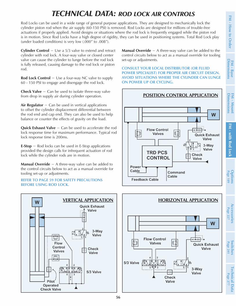
TECHNICAL DATA: ROD LOCK AIR CONTROLSRod Locks can be used in a wide range of general purpose applications. They are designed to mechanically lock the cylinder piston rod when the air supply (60-150 PSI) is removed. Rod Locks are designed for millions of trouble-free actuations if properly applied. Avoid designs or situations where the rod lock is frequently engaged while the piston rod is in motion. Since Rod Locks have a high degree of rigidity, they can be used in positioning systems. Total Rod Lock play (under loaded conditions) is very low (.000” to .008”).
Cylinder Control − Use a 5/3 valve to extend and retract cylinder with rod lock. A four-way valve or closed center valve can cause the cylinder to lunge before the rod lock is fully released, causing damage to the rod lock or piston rod.
Rod Lock Control − Use a four-way NC valve to supply 60 - 150 PSI to engage and disengage the rod lock.
Check Valve − Can be used to isolate three-way valve from drop in supply air during cylinder operation.
Air Regulator − Can be used in vertical applications to offset the cylinder displacement differential between the rod end and cap end. They can also be used to help balance or counter the effects of gravity on the load.
Quick Exhaust Valve − Can be used to accelerate the rod lock response time for maximum performance. Typical rod lock response time is 200ms.
E-Stop − Rod locks can be used in E-Stop applications provided the design calls for infrequent actuation of rod lock while the cylinder rods are in motion.
Manual Override − A three-way valve can be added to the control circuits below to act as a manual override for tooling set-up or adjustments.
Manual Override − A three-way valve can be added to the control circuits below to act as a manual override for tooling set-up or adjustments.
CONSULT YOUR LOCAL DISTRIBUTOR (OR FLUID POWER SPECIALIST) FOR PROPER AIR CIRCUIT DESIGN. AVOID SITUATIONS WHERE THE CYLINDER CAN LUNGE ON POWER UP OR CYCLING.
REFER TO PAGE 59 FOR SAFETY PRECAUTIONS BEFORE USING ROD LOCK.
HORIZONTAL APPLICATIONVERTICAL APPLICATION
POSITION CONTROL APPLICATION
FM - H
ow to O
rderFM
- Base D
imensions
FM - M
ount D
imensions
FM - w
ith Rod LockO
ptionsPage 189
AccessoriesPage 227
Switches
Page 241Technical D
ata Page 277

57
FM -
How
to
Ord
erFM
- B
ase
Dim
ensi
ons
FM -
Mou
nt
Dim
ensi
ons
FM -
with
Rod
Loc
kO
ptio
nsPa
ge 1
89Ac
cess
orie
sPa
ge 2
27Sw
itche
sPa
ge 2
41Te
chni
cal D
ata
Page
277
An inductive proximity switch (with M12x1 thread) can be used to sense the rod lock unclamped condition. Jam nuts are included and the switch is shipped unassembled (unthreaded) from the rod lock. BALLUFF Model: BES M08EH-PSC15B-S04G
PROXIMITY SWITCH SETTING INSTRUCTIONS1. Set the rod lock to the unclamped “pressure applied” position.
2. Screw the proximity switch (with jam nuts) into the designated M8x1 proximity switch hole until it contacts the position flange.
3. Unscrew (back off) the proximity switch approximately 3/4 turn. While holding the proximity switch in the set position, tighten the locking nut using 6 ft/lbs of torque. Final adjustment may be necessary to achieve desired results.
4. With the electrical power in the “off” position, connect the electrical wiring per the wiring diagram supplied with the switch. After the electrical power has been turned on, the proximity switch should indicate that the rod lock is in the unclamped position.
Notes: Ensure that the electrical power has been turned off before making adjustments. The locking nut should be tightened to a maximum of 15 ft/lbs of torque to prevent damage to the internal components of the switch. If sealing the unit for food or chemical service, make sure to include optional sealing ring.
ELECTRICAL DATAConnection type ConnectorEff. operating current Ie 200 mAEff. operating voltage Ue DC 24.0 VElectrical version DC, direct currentLoad capacitance max. (at Ue) 0.500 µFMax. no-load cur. lo undamped 3.0 mAMinimum operating current Im 0 mANo-load current lo damped max. 9.0 mAOperating voltage UB max. DC [V] 30.0 VOperating voltage UB min. DC [V] 10.0 VRated insulation voltage Ui 250 VACRated short circuit current 100 ARipple max. (% of Ue) 15%Switching freq. f max. (at Ue) 3000 HzSwitching function Normally open (NO)Switching output PNPVoltage drop static max. 2.5 V
MECHANICAL DATAAmbient temperature Ta max. 70°CAmbient temperature Ta min. -25°CAssured operating distance Sa 1.20 mmConnector type M12x1-S04Depth 58.0 mmDiameter d1 M08x1Eff. operating distance Sr 1.50 mmHousing material Stainless steelMech. installation condition Flush (shielded)Mounting length 43.0 mmRated operating distance Sn [mm] 1.50 mmSensing face material PBTTightening torque 8 Nm (6 FT-LBS)Function indicator YesFunction display LEDPolarity reversal protected YesShort circuit protected Yes
WIRING CONNECTIONS: PNP Normally Open
ROD LOCK PROXIMITY SWITCH: OPTION P

58
ROD LOCK INSTALLATION INSTRUCTIONS
SLEEVE NUT TORQUE SPECS
BORE TORQUE (FT/LBS)1.50 5 - 72.00 12 - 142.50 12 - 143.25 304.00 355.00 456.00 50
WARNING DO NOT DISASSEMBLE ROD LOCK! UNIT CONTAINS HIGH SPRING FORCE. RETURN TO TRD MANUFACTURING FOR SERVICE.
CAUTION DO NOT REMOVE 60-150 PSI AIR SUPPLY TO ROD LOCK UNIT WITHOUT SHIPPING ARBOR OR CYLINDER PISTON ROD IN PLACE! PERMANENT DAMAGE MAY OCCUR.
UNIT CONTAINS HIGH SPRING FORCE
DO NOT DISASSEMBLE − INJURY MAY OCCUR
Return to TRD Mfg. for serviceRefer to Rod Lock Catalog or visit www.trdmfg.com for complete instructions on proper use of rod lock.DO NOT REMOVE 60-150 PSI AIR SUPPLY TO ROD LOCK WHEN DIS-ASSEMBLED FROM CYLINDER. PERMANENT DAMAGE MAY OCCUR.
WARNING!
FM - H
ow to O
rderFM
- Base D
imensions
FM - M
ount D
imensions
FM - w
ith Rod LockO
ptionsPage 189
AccessoriesPage 227
Switches
Page 241Technical D
ata Page 277
Apply constant air supply to rod lock port (60-150 PSI).
Remove shipping arbor from inside rod lock. Save for future use.
Remove excess grease and dirt from cylinder piston rod. Slide rod lock onto piston rod, using care not to damage seals or bearings.
Align rod lock to cylinder so that unit is square and flush. Make sure that the cylinder is at least 1/2” extended.
Remove 60-150 PSI air supply to rod lock.
Fasten rod lock to cylinder using four (4) sleeve nuts & rods. Tighten sleeve nuts a little at a time, in a clockwise rotation, finishing with the proper torque specification.
Cycle Rod Lock by applying 60-150 PSI to rod lock port, then removing 60-150 PSI pressure; cycle several times in this man-ner.
Apply constant 60-150 PSI air supply to rod lock, then hand cycle the cylinder piston rod to check for proper alignment.
If cylinder piston rod does not move freely, remove rod lock and repeat Installation Instructions. If the piston rod still drags or is difficult to move, check the squareness of the Rod Lock to the cylinder.
Note: Faulty alignment will cause rod damage, cylinder failure and may drastically reduce holding force.
1)
2)
3)
4)
5)
6)
7)
8)
9)

59
SAFETY INFORMATION
DANGER! IF PERSONAL SAFETY IS REQUIRED, AN UNRELATED, REDUNDANTSAFETY SYSTEM IS REQUIRED TO PREVENT BODILY INJURY
WARNING! DO NOT DISASSEMBLE ROD LOCK - UNIT CONTAINS HIGH SPRING FORCE. Return to TRD Manufacturing for service.
WARNING!ROD LOCKS SHOULD BE INSTALLED, OPERATED AND MAINTAINED BY QUALIFIED PERSONNEL ONLY. UNITS SHOULD BE CHECKED PERIODICALLY FOR PROPER HOLDING FORCE.
GENERAL INFORMATION
One (or more rod locks) can be used on the same shaft or cylinder. Two units when combined will double the holding force. Steel cylinders should be considered in all high-load applications.
Rod locks are designed for static applications (rod not moving while engaging rod lock) and are suit-able for infrequent dynamic braking (E-Stop) when used with proper shafting materials. Repeated dynamic stops may cause rod and seal damage and/or rod lock wear resulting in reduced life or hold-ing force.
Filtered and dry air is important for proper rod lock functioning. Debris or moisture inside the rod lock may inhibit performance and/or shorten the life of the unit. Rod locks are pre-lubricated for life, no additional air lubrication is required.
The rod which the rod lock engages (clamps) must be kept clean and dry for optimum holding force.
The rod lock requires a minimum of 60 PSI to fully release. A low PSI condition (below 60 PSI) may cause the rod lock to drag on the rod, causing damage to the rod. Care should be taken to eliminate low PSI conditions.
Rod locks are intended for use with industrial compressed air systems within the operation specifications.
*
OPERATING PRESSURECylinder 0 TO 250 PSI AIRRod Lock 60 TO 150 PSI AIR
AXIAL MOVEMENT (CLAMPED)*Standard .001” to .008”
Close Tol. (Optional) .001” to .003”
OPERATING TEMPERATUREStandard Seals 10°F to 180°F (-12°C to 82°C )
Fluorocarbon Seals 0°F to 400°F (-18°C to 204°C)
ROD MATERIAL REQUIREMENTSDiameter +.000” to -.002” Nominal Diameter
Hardened Shaft .0005” Minimum hard chromeUnhardened Shaft .001” Minimum hard chrome
Finish 6 to 10 Ra
FM -
How
to
Ord
erFM
- B
ase
Dim
ensi
ons
FM -
Mou
nt
Dim
ensi
ons
FM -
with
Rod
Loc
kkO
ptio
nsPa
ge 1
89Ac
cess
orie
sPa
ge 2
27Sw
itche
sPa
ge 2
41Te
chni
cal D
ata
Page
277 Represents clearance within the rod lock unit,
.000” movement due to actuation.