series fs4-3 general purpose liquid flow...
TRANSCRIPT
INSTRUCTION MANUAL
Series FS4-3General PurposeLiquid Flow Switch
• Before using product, read and understand instructions.• Save these instructions for future reference.• All work must be performed by qualified personnel trained in the proper application,
installation, and maintenance of plumbing, steam and electrical equipment and/or systems inaccordance with all applicable codes and ordinances.
• To prevent electrical shock, turn off the electrical power before making electricalconnections.
• To prevent an electrical fire or equipment damage, electrical wiring insulation must have a rating of 167˚F (75˚C) if the liquid’s temperature exceeds 180˚F (82˚C).
• To prevent electrocution, when the electrical power is connected to the flow switch, do not touch the terminals.
• Make sure flow switch electrical cover is secured before turning on electric power.
• Liquid m edia containing deb ris or other particulates should b e filtered to avoid dam ageto or ob struction of the flow switch paddle arm assem b ly, which could cause the flowSwitch to m alfunction.
MM-601G
California Proposition 65 warning! This product contains chemicals known to the•state of California to cause cancer and birth defects or other reproductive harm.Previous controls should never be installed on a new system. Always install new•controls on a new boiler or system.
CAUTION:A more frequent replacement interval may be necessary based on the condition ofthe unit at time of inspection. McDonnell Miller s warranty is one (1) year from dateof installation or two (2) years from the date of manufacture.
�
Failure to follow this warning could cause property damage, personal inj ury or death.
•
!
& '
2
Maximum Liquid Pressure: 160 psi (11.3 kg/cm2)
Liquid Temperature Range (TL): 32 - 300˚F (0 - 149˚C)
Ambient Temperature Range (TS): 32 - 120˚F (0 - 49˚C)
Electrical Enclosure Rating: Nema Type 1 (IP 21)
Maximum Velocity: 10ft/sec (3M/sec)
Pipe Connection Thread Size: - 1" NPT - All models except “J”
- 1" BSPT - “J” models
Models that meet CE Conformance:FS4-3D-E
FS4-3J-E
FS4-3S-E
• This Control: is for continuous operationsis not electronichas Type 1C action (micro interruption on operation)
• LVD 73/23/EEC
• EMC 89/33/EECFor applications with loads between 14mA and 3.7Amps, power factors exceeding 0.65, an anticipated
system switch operation rate of less than 5 times perminute, and any one cycle greater than 3 seconds onand 3 seconds off.
Additional suppression may be required for applica-tions outside these ranges.
• Declaration of ConformityAvailable on request.
SPECIFICATIONS
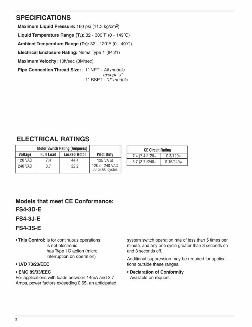
CE Circuit Rating7.4 (7.4)/120~ 0.3/120=3.7 (3.7)/240~ 0.15/240=
Motor Switch Rating (Amperes)Voltage Full Load Locked Rotor Pilot Duty120 VAC 7.4 44.4 125 VA at240 VAC 3.7 22.2 120 or 240 VAC
50 or 60 cycles
ELECTRICAL RATINGS
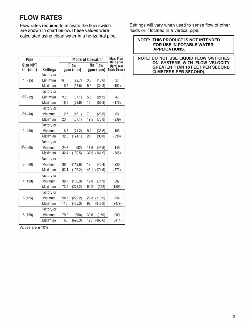
FLOW RATESSettings will vary when used to sense flow of otherfluids or if located in a vertical pipe.
3
NOTE: DO NOT USE LIQUID FLOW SWITCHESON SYSTEMS WITH FLOW VELOCITYGREATER THAN 10 FEET PER SECOND(3 METERS PER SECOND).
Values are ± 10%
Pipe Mode of OperationSize NPT Flow No Flowin. (mm) Settings gpm (lpm) gpm (lpm)
Factory or
1 (25) Minimum 6 (22.7) 3.6 (13.6) 27Maximum 10.2 (38.6) 9.2 (34.8) (102)
Factory or
11⁄4 (32) Minimum 9.8 (37.1) 5.6 (21.2) 47Maximum 16.8 (63.6) 15 (56.8) (178)
Factory or
11⁄2 (40) Minimum 12.7 (48.1) 7 (26.5) 63Maximum 23 (87.1) 19.5 (73.8) (239)
Factory or
2 (50) Minimum 18.8 (71.2) 9.4 (35.6) 105Maximum 32.8 (124.1) 24 (90.8) (398)
Factory or
21⁄2 (65) Minimum 24.3 (92) 11.6 (43.9) 149Maximum 42.4 (160.5) 37.5 (141.9) (565)
Factory or
3 (80) Minimum 30 (113.6) 12 (45.4) 230Maximum 52.1 (197.2) 46.1 (174.5) (872)
Factory or
4 (100) Minimum 39.7 (150.3) 19.8 (74.9) 397Maximum 73.5 (278.2) 64.2 (242) (1505)
Factory or
5 (125) Minimum 58.7 (222.2) 29.3 (110.9) 654Maximum 115 (435.3) 92 (348.2) (2479)
Factory or
6 (150) Minimum 79.2 (300) 39.6 (150) 900Maximum 166 (628.3) 123 (465.6) (3411)
Max. FlowRate gpm(lpm) w/o
Paddle Damage
calculated using clean water in a horizontal pipe.
Flow rates required to activate the flow switchare shown in chart below.These values were
NOTE: THIS PRODUCT IS NOT INTENDED FOR USE IN POTABLE WATERAPPLICATIONS.
4
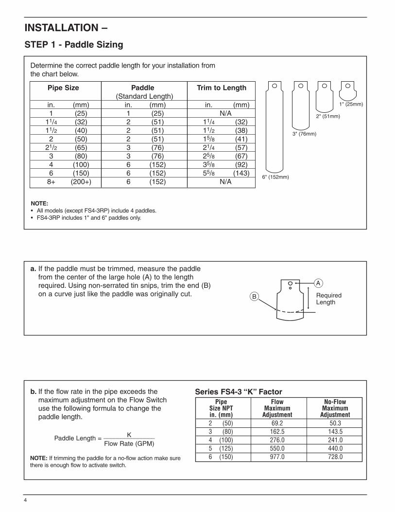
Pipe Flow No-FlowSize NPT Maximum Maximumin. (mm) Adjustment Adjustment2 (50) 69.2 50.33 (80) 162.5 143.54 (100) 276.0 241.05 (125) 550.0 440.06 (150) 977.0 728.0
Series FS4-3 “K” Factorb. If the flow rate in the pipe exceeds the maximum adjustment on the Flow Switch use the following formula to change the paddle length.
Paddle Length = K_______________Flow Rate (GPM)
NOTE: If trimming the paddle for a no-flow action make surethere is enough flow to activate switch.
a. If the paddle must be trimmed, measure the paddlefrom the center of the large hole (A) to the length required. Using non-serrated tin snips, trim the end (B) on a curve just like the paddle was originally cut.
STEP 1 - Paddle Sizing
1" (25mm)
2" (51mm)
3" (76mm)
6" (152mm)
Determine the correct paddle length for your installation fromthe chart below.
NOTE:• All models (except FS4-3RP) include 4 paddles.• FS4-3RP includes 1" and 6" paddles only.
INSTALLATION –
Pipe Size Paddle Trim to Length(Standard Length)
in. (mm) in. (mm) in. (mm)1 (25) 1 (25) N/A
11/4 (32) 2 (51) 11/4 (32)11/2 (40) 2 (51) 11/2 (38)2 (50) 2 (51) 15/8 (41)
21/2 (65) 3 (76) 21/4 (57)3 (80) 3 (76) 25/8 (67)4 (100) 6 (152) 35/8 (92)6 (150) 6 (152) 55/8 (143)
8+ (200+) 6 (152) N/A
5
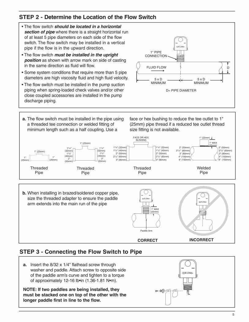
STEP 2 - Determine the Location of the Flow Switch
a. The flow switch must be installed in the pipe using a threaded tee connection or welded fitting of minimum length such as a half coupling. Use a
face or hex bushing to reduce the tee outlet to 1"(25mm) pipe thread if a reduced tee outlet threadsize fitting is not available.
• The flow switch should be located in a horizontalsection of pipe where there is a straight horizontal runof at least 5 pipe diameters on each side of the flowswitch. The flow switch may be installed in a verticalpipe if the flow is in the upward direction.
• The flow switch must be installed in the uprightposition as shown with arrow mark on side of castingin the same direction as fluid will flow.
• Some system conditions that require more than 5 pipediameters are high viscosity fluid and high fluid velocity.
• The flow switch must be installed in the pump suctionpiping when spring-loaded check valves and/or otherclose coupled accessories are installed in the pump discharge piping.
1" (25mm)
1"(25mm)
1"(25mm)
ThreadedPipe
ThreadedPipe
ThreadedPipe
WeldedPipe
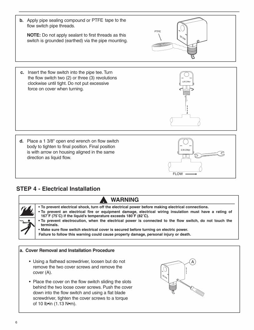
b. When installing in brazed/soldered copper pipe, size the threaded adapter to ensure the paddle arm extends into the main run of the pipe
STEP 3 - Connecting the Flow Switch to Pipe
FLOW
a. Insert the 8/32 x 1/4" flathead screw through washer and paddle. Attach screw to opposite side of the paddle arm’s curve and tighten to a torque of approximately 12-16 lb•in (1.36-1.81 N•m).
NOTE: If two paddles are being installed, theymust be stacked one on top of the other with thelonger paddle first in line to the flow.
CORRECT INCORRECT
a. Cover Removal and Installation Procedure
• Using a flathead screwdriver, loosen but do notremove the two cover screws and remove thecover (A).
• Place the cover on the flow switch sliding the slotsbehind the two loose cover screws. Push the coverdown into the flow switch and using a flat bladescrewdriver, tighten the cover screws to a torqueof 10 lb•in (1.13 N•m).
STEP 4 - Electrical Installation
• To prevent electrical shock, turn off the electrical power before making electrical connections.• To prevent an electrical fire or equipment damage, electrical wiring insulation must have a rating of
167˚F (75˚C) if the liquid’s temperature exceeds 180˚F (82˚C).• To prevent electrocution, when the electrical power is connected to the flow switch, do not touch the
terminals.• Make sure flow switch electrical cover is secured before turning on electric power.Failure to follow this warning could cause property damage, personal injury or death.
6
! WARNING
c. Insert the flow switch into the pipe tee. Turn the flow switch two (2) or three (3) revolutions clockwise until tight. Do not put excessive force on cover when turning.
d. Place a 1 3/8" open end wrench on flow switchbody to tighten to final position. Final position is with arrow on housing aligned in the same direction as liquid flow.
b. Apply pipe sealing compound or PTFE tape to the flow switch pipe threads.
NOTE: Do not apply sealant to first threads as this switch is grounded (earthed) via the pipe mounting.
PTFE
7
b. Electrical Conduit Connection
• Connect electric conduit to flow switch electrical enclosure.• Follow accepted electrical practices when installing fittings and making connections.• Refer to and follow local codes and standards when selecting the types of electrical fittings and conduit to
connect to flow switch.
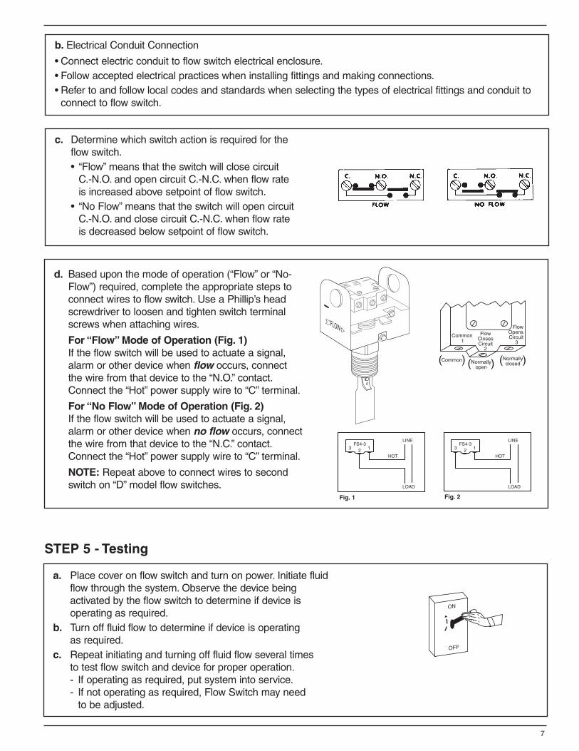
c. Determine which switch action is required for the flow switch.• “Flow” means that the switch will close circuit
C.-N.O. and open circuit C.-N.C. when flow rate is increased above setpoint of flow switch.
• “No Flow” means that the switch will open circuit C.-N.O. and close circuit C.-N.C. when flow rate is decreased below setpoint of flow switch.
a. Place cover on flow switch and turn on power. Initiate fluid flow through the system. Observe the device being activated by the flow switch to determine if device is operating as required.
b. Turn off fluid flow to determine if device is operating as required.
c. Repeat initiating and turning off fluid flow several times to test flow switch and device for proper operation.- If operating as required, put system into service.- If not operating as required, Flow Switch may need
to be adjusted.
d. Based upon the mode of operation (“Flow” or “No-Flow”) required, complete the appropriate steps to connect wires to flow switch. Use a Phillip’s head screwdriver to loosen and tighten switch terminal screws when attaching wires.
For “Flow” Mode of Operation (Fig. 1)If the flow switch will be used to actuate a signal, alarm or other device when flow occurs, connect the wire from that device to the “N.O.” contact.Connect the “Hot” power supply wire to “C” terminal.
For “No Flow” Mode of Operation (Fig. 2)If the flow switch will be used to actuate a signal, alarm or other device when no flow occurs, connect the wire from that device to the “N.C.” contact.Connect the “Hot” power supply wire to “C” terminal.
NOTE: Repeat above to connect wires to second switch on “D” model flow switches.
STEP 5 - Testing
Xylem Inc.
8200 N. Austin Avenue Morton Grove, Illinois 60053 Phone: (847) 966-3700 Fax: (847) 965-8379www.xyleminc.com/brands/mcdonnellmiller
McDonnell & Miller is a trademark of Xylem Inc. or one of its subsidiaries. © 2013 Xylem Inc. MM-601G July 2013 Part No. 246796