series gb control valves globe-cage balanced, cage...
TRANSCRIPT
4 GV
25 EN •
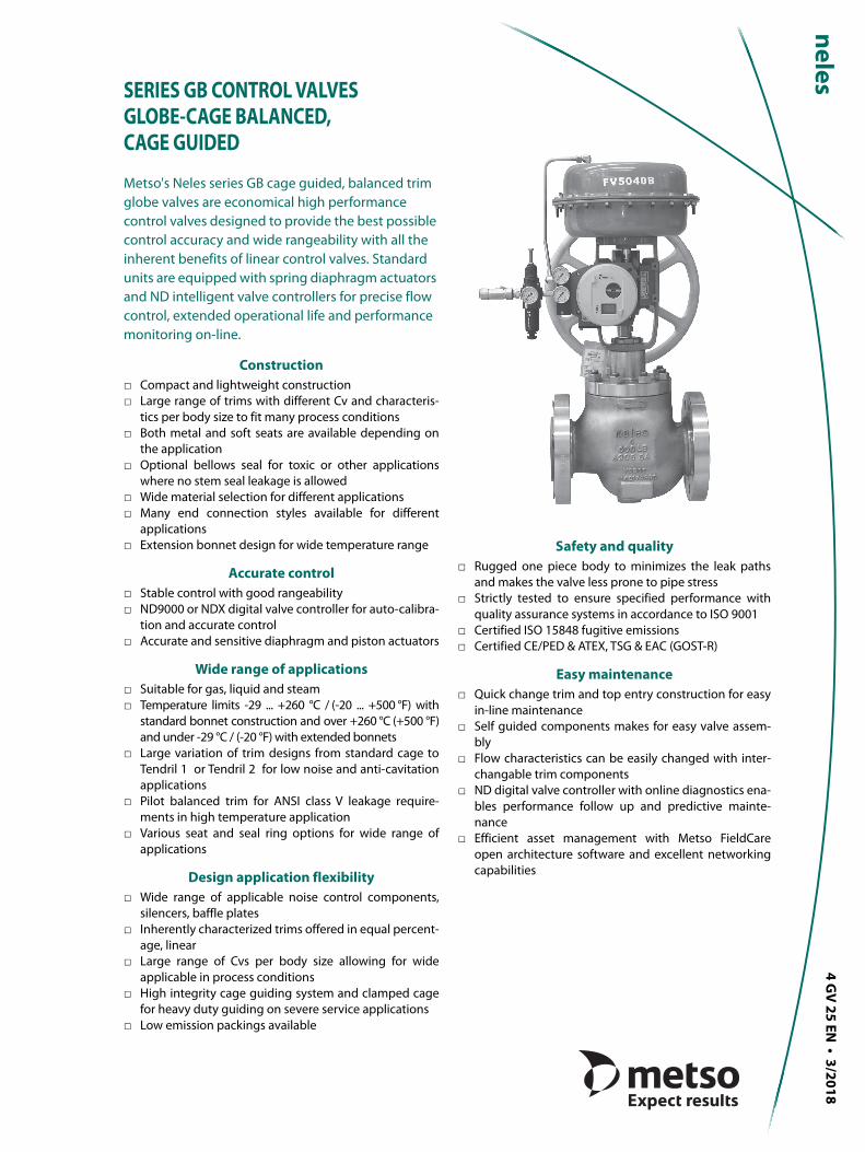
SERIES GB CONTROL VALVESGLOBE-CAGE BALANCED, CAGE GUIDED
Metso's Neles series GB cage guided, balanced trim globe valves are economical high performance control valves designed to provide the best possible control accuracy and wide rangeability with all the inherent benefits of linear control valves. Standard units are equipped with spring diaphragm actuators and ND intelligent valve controllers for precise flow control, extended operational life and performance monitoring on-line.
Construction□ Compact and lightweight construction□ Large range of trims with different Cv and characteris-
tics per body size to fit many process conditions□ Both metal and soft seats are available depending on
the application□ Optional bellows seal for toxic or other applications
where no stem seal leakage is allowed□ Wide material selection for different applications□ Many end connection styles available for different
applications□ Extension bonnet design for wide temperature range
Accurate control□ Stable control with good rangeability□ ND9000 or NDX digital valve controller for auto-calibra-
tion and accurate control□ Accurate and sensitive diaphragm and piston actuators
Wide range of applications□ Suitable for gas, liquid and steam□ Temperature limits -29 ... +260 °C / (-20 ... +500 °F) with
standard bonnet construction and over +260 °C (+500 °F)and under -29 °C / (-20 °F) with extended bonnets
□ Large variation of trim designs from standard cage toTendril 1 or Tendril 2 for low noise and anti-cavitationapplications
□ Pilot balanced trim for ANSI class V leakage require-ments in high temperature application
□ Various seat and seal ring options for wide range ofapplications
Design application flexibility□ Wide range of applicable noise control components,
silencers, baffle plates□ Inherently characterized trims offered in equal percent-
age, linear □ Large range of Cvs per body size allowing for wide
applicable in process conditions□ High integrity cage guiding system and clamped cage
for heavy duty guiding on severe service applications□ Low emission packings available
Safety and quality□ Rugged one piece body to minimizes the leak paths
and makes the valve less prone to pipe stress□ Strictly tested to ensure specified performance with
quality assurance systems in accordance to ISO 9001□ Certified ISO 15848 fugitive emissions□ Certified CE/PED & ATEX, TSG & EAC (GOST-R)
Easy maintenance□ Quick change trim and top entry construction for easy
in-line maintenance□ Self guided components makes for easy valve assem-
bly□ Flow characteristics can be easily changed with inter-
changable trim components□ ND digital valve controller with online diagnostics ena-
bles performance follow up and predictive mainte-nance
□ Efficient asset management with Metso FieldCareopen architecture software and excellent networkingcapabilities
3/2018
M E T S O
2
4 G V 2 5 E N
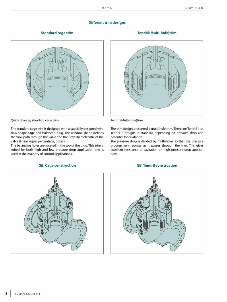
Different trim designs
Standard cage trim
Quick change, standard cage trim
The standard cage trim is designed with a specially designed win-dow shape cage and balanced plug. The window shape definesthe flow path through the valve and the flow characteristic of thevalve (linear, equal percentage, others ).The balancing holes are located in the top of the plug. This trim issuited for both high and low pressure drop application and isused in the majority of control applications.
GB, Cage construction
Tendril(Multi-hole)trim
Tendril(Multi-hole)trim
The trim design presented a multi-hole trim. There are Tendril 1 orTendril 2 designs in standard depending on pressure drop andpotential for cavitation.The pressure drop is divided by multi-holes so that the pressureprogressively reduces as it passes through the trim. This givesexcellent resistance to cavitation on high pressure drop applica-tions.
GB, Tendril construction
TECHNICAL BULLETIN 3/18
S E R I E S G B C O N T R O L V A L V E S G L O B E - C A G E B A L A N C E D , C A G E G U I D E D4 G V 2 5 E N
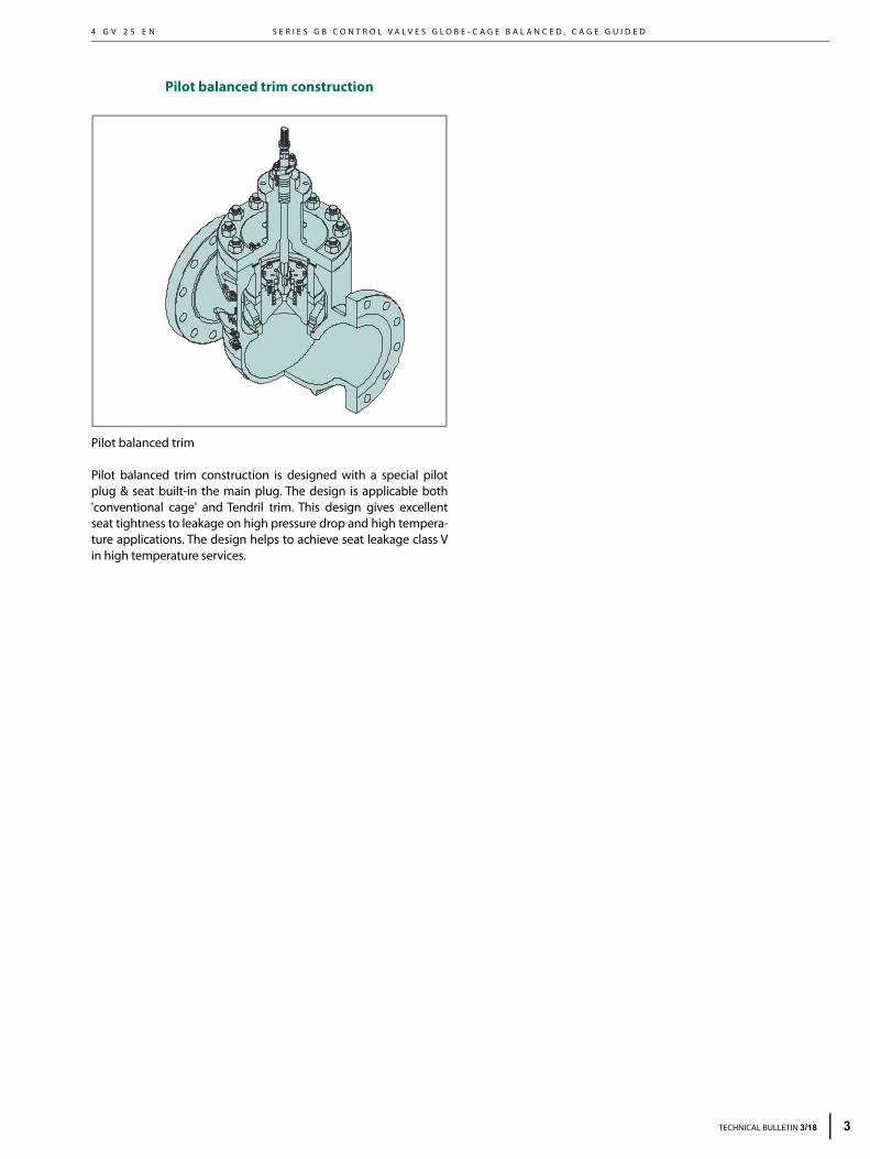
Pilot balanced trim construction
Pilot balanced trim
Pilot balanced trim construction is designed with a special pilotplug & seat built-in the main plug. The design is applicable both'conventional cage' and Tendril trim. This design gives excellentseat tightness to leakage on high pressure drop and high tempera-ture applications. The design helps to achieve seat leakage class Vin high temperature services.
TECHNICAL BULLETIN 3/18 3
M E T S O
4
4 G V 2 5 E N
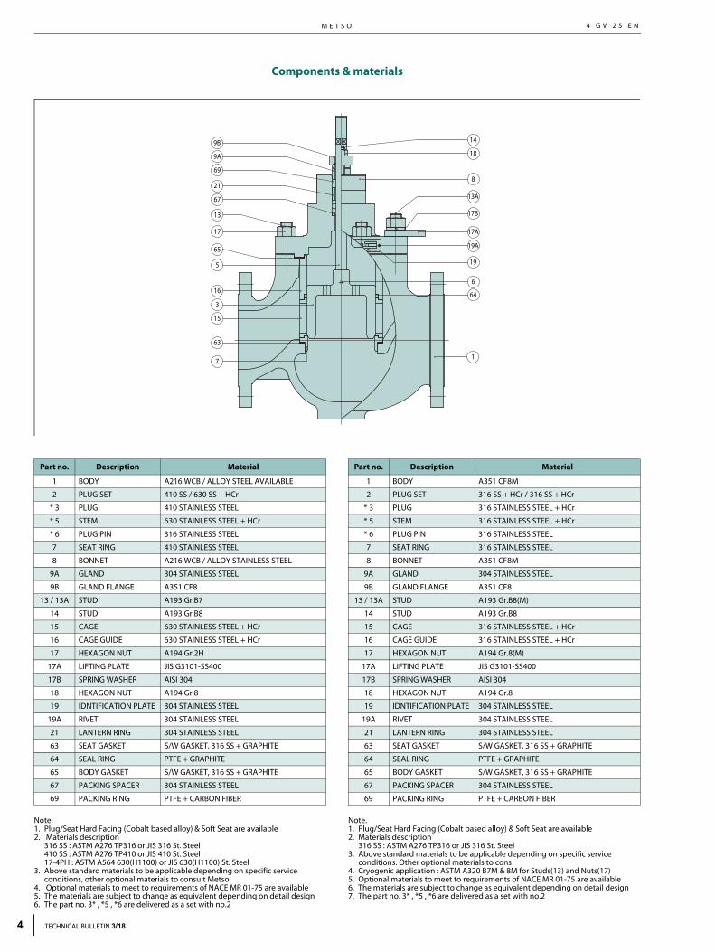
Components & materials
Note.1. Plug/Seat Hard Facing (Cobalt based alloy) & Soft Seat are available2. Materials description
316 SS : ASTM A276 TP316 or JIS 316 St. Steel410 SS : ASTM A276 TP410 or JIS 410 St. Steel17-4PH : ASTM A564 630(H1100) or JIS 630(H1100) St. Steel
3. Above standard materials to be applicable depending on specific service conditions, other optional materials to consult Metso.
4. Optional materials to meet to requirements of NACE MR 01-75 are available5. The materials are subject to change as equivalent depending on detail design6. The part no. 3* , *5 , *6 are delivered as a set with no.2
Note.1. Plug/Seat Hard Facing (Cobalt based alloy) & Soft Seat are available2. Materials description
316 SS : ASTM A276 TP316 or JIS 316 St. Steel3. Above standard materials to be applicable depending on specific service
conditions. Other optional materials to cons4. Cryogenic application : ASTM A320 B7M & 8M for Studs(13) and Nuts(17)5. Optional materials to meet to requirements of NACE MR 01-75 are available6. The materials are subject to change as equivalent depending on detail design7. The part no. 3* , *5 , *6 are delivered as a set with no.2
9A
69
21
67
13
17
65
16
15
63
7
8
19A
19
64
1
13A
17B
17A
3
9B
5
6
14
18
DATE
II 2 GD
235 Cheomdansaneop 1-ro, Daesowon-myeon,Chungju-si, Chungcheongbuk-do, Korea ., Ltd.
GROUP
Part no. Description Material
1 BODY A216 WCB / ALLOY STEEL AVAILABLE
2 PLUG SET 410 SS / 630 SS + HCr
* 3 PLUG 410 STAINLESS STEEL
* 5 STEM 630 STAINLESS STEEL + HCr
* 6 PLUG PIN 316 STAINLESS STEEL
7 SEAT RING 410 STAINLESS STEEL
8 BONNET A216 WCB / ALLOY STAINLESS STEEL
9A GLAND 304 STAINLESS STEEL
9B GLAND FLANGE A351 CF8
13 / 13A STUD A193 Gr.B7
14 STUD A193 Gr.B8
15 CAGE 630 STAINLESS STEEL + HCr
16 CAGE GUIDE 630 STAINLESS STEEL + HCr
17 HEXAGON NUT A194 Gr.2H
17A LIFTING PLATE JIS G3101-SS400
17B SPRING WASHER AISI 304
18 HEXAGON NUT A194 Gr.8
19 IDNTIFICATION PLATE 304 STAINLESS STEEL
19A RIVET 304 STAINLESS STEEL
21 LANTERN RING 304 STAINLESS STEEL
63 SEAT GASKET S/W GASKET, 316 SS + GRAPHITE
64 SEAL RING PTFE + GRAPHITE
65 BODY GASKET S/W GASKET, 316 SS + GRAPHITE
67 PACKING SPACER 304 STAINLESS STEEL
69 PACKING RING PTFE + CARBON FIBER
Part no. Description Material
1 BODY A351 CF8M
2 PLUG SET 316 SS + HCr / 316 SS + HCr
* 3 PLUG 316 STAINLESS STEEL + HCr
* 5 STEM 316 STAINLESS STEEL + HCr
* 6 PLUG PIN 316 STAINLESS STEEL
7 SEAT RING 316 STAINLESS STEEL
8 BONNET A351 CF8M
9A GLAND 304 STAINLESS STEEL
9B GLAND FLANGE A351 CF8
13 / 13A STUD A193 Gr.B8(M)
14 STUD A193 Gr.B8
15 CAGE 316 STAINLESS STEEL + HCr
16 CAGE GUIDE 316 STAINLESS STEEL + HCr
17 HEXAGON NUT A194 Gr.8(M)
17A LIFTING PLATE JIS G3101-SS400
17B SPRING WASHER AISI 304
18 HEXAGON NUT A194 Gr.8
19 IDNTIFICATION PLATE 304 STAINLESS STEEL
19A RIVET 304 STAINLESS STEEL
21 LANTERN RING 304 STAINLESS STEEL
63 SEAT GASKET S/W GASKET, 316 SS + GRAPHITE
64 SEAL RING PTFE + GRAPHITE
65 BODY GASKET S/W GASKET, 316 SS + GRAPHITE
67 PACKING SPACER 304 STAINLESS STEEL
69 PACKING RING PTFE + CARBON FIBER
TECHNICAL BULLETIN 3/18
S E R I E S G B C O N T R O L V A L V E S G L O B E - C A G E B A L A N C E D , C A G E G U I D E D4 G V 2 5 E N
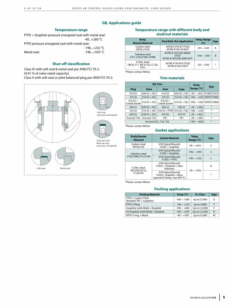
GB, Applications guide
Temperature rangePTFE + Graphite pressure energized seal with metal seat:
-40...+260 °C PTFE pressure energized seal with metal seat:
-196...+232 °C Metal seat: -196...+593 °C
Shut-off classification Class IV with soft seal & metal seat per ANSI FCI 70-2. (0.01 % of valve rated capacity). Class V with soft seat or pilot balanced plug per ANSI FCI 70-2.
Temperature range with different body andstud/nut materials
*Please contact Metso
Trim materials
*Please contact Metso
Gasket applications
*Please contact Metso
Packing applications
Soft seal(pressure enerqized)
Soft seal withBack-up ring(pressure enerqized)
Metal seatSoft seat
Body,Bonnet Material
Stud Bolt, Nut ApplicationTemp. Range
(°C)Sign
Carbon steel(WCB, A105)
ASTM A193-B7 STUD ASTM A194-2H NUT -29 ~ +425 A
Stainless steel(CF3, CF8,CF3M, CF8M)
ASTM A193(320)-B8(M) STUD
ASTM A194(320)-8(M) NUT-196 ~ +593 B
Cr.Mo. Steel(WC6, F11, WC9, F22, C12A,
F91)
ASTM A193-B16 STUD ASTM A194-4 NUT -29 ~ +593 *
GB, Trim Temp.Range (°C)
SignPlug Stem Seat Cage
410 SS 630 SS + HCr 410 SS 630 SS + HCr -29 ~ +425 P1XBCS1R1X316 SS 316 SS + HCr 316 SS 316 SS + HCr -196 ~ +425 T6XTCS1R6X
316 SS +Cobalt based 316 SS + HCr 316 SS +
Cobalt based 316 SS + HCr -196 ~ +425 T6ATCS1R6A
420 J2 630 SS + HCr 420 J2 420 J2 -29 ~ +500 *316 SS 316 SS + HCr 316 SS + PTFE 316 SS + HCr -196 ~ +232 *630 SS 630 SS + HCr 410 SS 410 SS -29 ~ +425 *
Inconel 718 Inconel 718 F91 F91 -29 ~ +593 *Inconel 625, 718, 750 -196 ~ +645 *
Body,Bonnet Material
Gasket MaterialTemp.
Range (°C)Sign
Carbon steelWCB,A105
S/W (Spiral Wound)316SS + Graphite -29 ~ +425 S
Stainless steelCF8,CF8M,CF3,CF3M
S/W (Spiral Wound)316SS + Graphite -196 ~ +593 S
S/W (Spiral Wound)316SS + PTFE -196 ~ +232 L
Cr.Mo. SteelWC6,WC9,F22,
C12A,F91
S/W (Spiral Wound)316SS + Graphite + Non
Asbestos-29 ~ +593
H
S/W (Spiral Wound)316SS+ Graphite + Mica
(special Hi-Temp. max 950 °C)*
Packing Material Temp (°C) Pr. Class SignPTFE + Carbon Fiber (Braided TEF + Graphite) -196 ~ +260 Up to CL900 G
PTFE V-Ring - 196 ~ +232 Up to Cl600 TGraphite (with Mold + Braided) -196 ~ +400 Up to CL2500 FHi-Graphite (with Mold + Braided) -196 ~ +593 Up to CL2500 HRTFE V ring + Metal - 40 ~ +350 Up to CL600 M
TECHNICAL BULLETIN 3/18 5
M E T S O
6
4 G V 2 5 E N
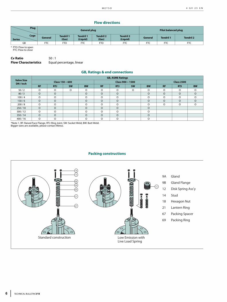
Flow directions
* FTO: Flow to openFTC: Flow to close
Cv Ratio 50 : 1 Flow Characteristics Equal percentage, linear
GB, Ratings & end connections
*Note 1. RF: Raised Face Flange, RTJ: Ring Joint, SW: Socket Weld, BW: Butt Weld.Bigger sizes are available, please contact Metso.
Packing constructions
Plug
CageSeries
General plug Pilot balanced plug
General Tendril 1(Gas)
Tendril 1(Liquid)
Tendril 2(Gas)
Tendril 2(Liquid) General Tendril 1 Tendril 2
GB FTC FTO FTC FTO FTC FTC FTC FTC
Valve SizeDN / Inch
GB, ASME Ratings
Class 150 ~ 600 Class 900 ~ 1500 Class 2500
RF RTJ SW BW RF RTJ SW BW RF RTJ BW 50 / 2 O O O O O O O O O O O 80 / 3 O O O O O O O O O100 / 4 O O O O O O O O O150 / 6 O O O O O O O O O200 / 8 O O O O O O O O O
250 / 10 O O O O O O300 / 12 O O O O O O350 / 14 O O O O O O400 / 16 O O O O O O
9B
Standard construction
Packing Ring
21
Packing Spacer
9A
Lantern Ring
67
Gland
69
Gland Flange
Hexagon Nut18
12 Disk Spring Ass'y
Low Emission withLive Load Spring
9A
9B
21
67
69
14
18
12
Stud14
TECHNICAL BULLETIN 3/18

S E R I E S G B C O N T R O L V A L V E S G L O B E - C A G E B A L A N C E D , C A G E G U I D E D4 G V 2 5 E N
Rated Cv and trim table (Globe Single seat, Cage Balanced Type, Series GB)
NOTE1. Rated Cvs are applied differently depending on the trim type & trim characreistics.2. The bigger Cvs and sizes are available, please contact Metso.3. (Srk) means the valve stroke in mm.4. The other Cvs and trim types : please contact Metso.
Sign TRIM TYPE Sign TRIMCharacte-ristic Sign
GB , RATED Cv
Desc. 2" (Srk) 3" (Srk) 4" (Srk) 6" (Srk) 8" (Srk) 10" (Srk) 12" (Srk) 14" (Srk) 16" (Srk)
A General Plug Type L Linear FC Full Cv 74 (40) 142 (50) 230 (50) 380 (60) 600 (70) 950 (80) 1270 (120) 1740 (140) 2215 (160)
P Pilot Balanced Plug Type 1A 1-Step 48 (40) 98 (50) 160 (50) 275 (60) 455 (70) 700 (80) 970 (120) 1300 (140) 1530 (160)
2A 2-Step 26 (40) 56 (50) 86 (50) 150 (60) 254 (70) 398 (80) 550 (120) 776 (140) 940 (160)
3A 3-Step 16 (40) 34 (50) 52 (50) 90 (60) 152 (70) 238 (80) 340 (120) 464 (140) 568 (160)
FT Full Cv 64 (40) 138 (50) 210 (50) 370 (60) 610 (70) 960 (80) 1320 (120) 1890 (140) 2300 (160)
1T 1-Step 38 (40) 84 (50) 128 (50) 220 (60) 365 (70) 580 (80) 794 (120) 1136 (140) 1384 (160)
2T 2-Step 22 (40) 52 (50) 78 (50) 132 (60) 224 (70) 348 (80) 476 (120) 682 (140) 836 (160)
3T 3-Step 14 (40) 32 (50) 46 (50) 82 (60) 134 (70) 208 (80) 286 (120) 410 (140) 500 (160)
FM Full Cv 44 (40) 96 (50) 146 (50) 258 (60) 428 (70) 676 (80) 920 (120) 1320 (140) 1610 (160)
1M 1-Step 26 (40) 58 (50) 88 (50) 154 (60) 256 (70) 406 (80) 554 (120) 796 (140) 968 (160)
2M 2-Step 16 (40) 34 (50) 52 (50) 92 (60) 154 (70) 242 (80) 332 (120) 478 (140) 580 (160)
3M 3-Step 10 (40) 20 (50) 32 (50) 56 (60) 92 (70) 146 (80) 200 (120) 286 (140) 348 (160)
E Equal % FC Full Cv 71 (40) 138 (50) 210 (50) 340 (60) 560 (70) 830 (80) 1240 (120) 1650 (140) 2090 (160)
1A 1-Step 50 (40) 110 (50) 160 (50) 270 (60) 450 (70) 655 (80) 960 (120) 1275 (140) 1680 (160)
2A 2-Step 24 (40) 50 (50) 82 (50) 136 (60) 236 (70) 374 (80) 524 (120) 746 (140) 854 (160)
3A 3-Step 14 (40) 32 (50) 50 (50) 82 (60) 142 (70) 224 (80) 314 (120) 446 (140) 512 (160)
FT Full Cv 54 (40) 124 (50) 200 (50) 336 (60) 570 (70) 880 (80) 1260 (120) 1760 (140) 2080 (160)
1T 1-Step 32 (40) 74 (50) 124 (50) 200 (60) 340 (70) 520 (80) 758 (120) 1060 (140) 1248 (160)
2T 2-Step 20 (40) 46 (50) 76 (50) 120 (60) 204 (70) 310 (80) 456 (120) 638 (140) 750 (160)
3T 3-Step 12 (40) 28 (50) 48 (50) 72 (60) 124 (70) 186 (80) 278 (120) 382 (140) 454 (160)
FM Full Cv 38 (40) 86 (50) 140 (50) 234 (60) 400 (70) 620 (80) 880 (120) 1240 (140) 1460 (160)
1M 1-Step 22 (40) 52 (50) 84 (50) 140 (60) 240 (70) 372 (80) 528 (120) 746 (140) 876 (160)
2M 2-Step 14 (40) 32 (50) 54 (50) 84 (60) 146 (70) 224 (80) 320 (120) 448 (140) 524 (160)
3M 3-Step 8 (40) 18 (50) 30 (50) 50 (60) 88 (70) 134 (80) 194 (120) 268 (140) 316 (160)
TECHNICAL BULLETIN 3/18 7
M E T S O
8
4 G V 2 5 E N
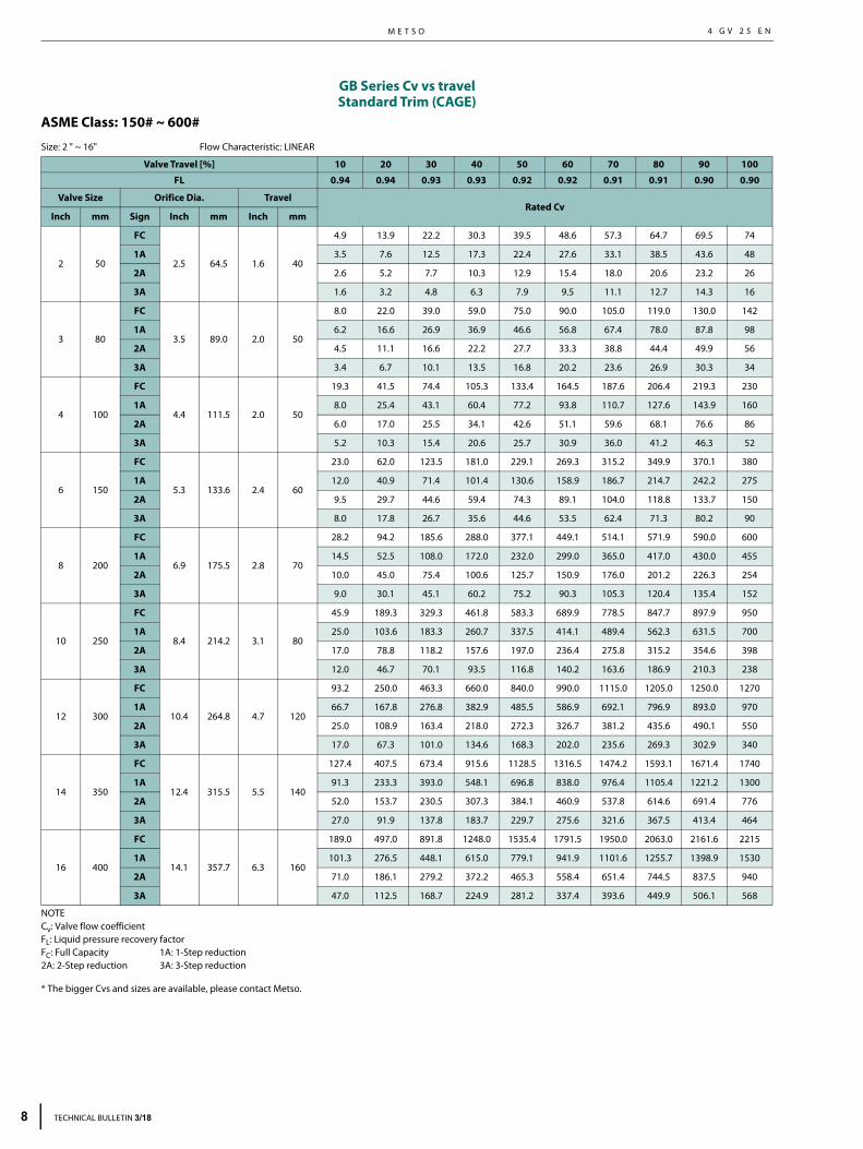
GB Series Cv vs travelStandard Trim (CAGE)
ASME Class: 150# ~ 600# Size: 2 " ~ 16" Flow Characteristic: LINEAR
NOTECv: Valve flow coefficientFL: Liquid pressure recovery factorFC: Full Capacity 1A: 1-Step reduction2A: 2-Step reduction 3A: 3-Step reduction
* The bigger Cvs and sizes are available, please contact Metso.
Valve Travel [%] 10 20 30 40 50 60 70 80 90 100
FL 0.94 0.94 0.93 0.93 0.92 0.92 0.91 0.91 0.90 0.90
Valve Size Orifice Dia. TravelRated Cv
Inch mm Sign Inch mm Inch mm
2 50
FC
2.5 64.5 1.6 40
4.9 13.9 22.2 30.3 39.5 48.6 57.3 64.7 69.5 74
1A 3.5 7.6 12.5 17.3 22.4 27.6 33.1 38.5 43.6 48
2A 2.6 5.2 7.7 10.3 12.9 15.4 18.0 20.6 23.2 26
3A 1.6 3.2 4.8 6.3 7.9 9.5 11.1 12.7 14.3 16
3 80
FC
3.5 89.0 2.0 50
8.0 22.0 39.0 59.0 75.0 90.0 105.0 119.0 130.0 142
1A 6.2 16.6 26.9 36.9 46.6 56.8 67.4 78.0 87.8 98
2A 4.5 11.1 16.6 22.2 27.7 33.3 38.8 44.4 49.9 56
3A 3.4 6.7 10.1 13.5 16.8 20.2 23.6 26.9 30.3 34
4 100
FC
4.4 111.5 2.0 50
19.3 41.5 74.4 105.3 133.4 164.5 187.6 206.4 219.3 230
1A 8.0 25.4 43.1 60.4 77.2 93.8 110.7 127.6 143.9 160
2A 6.0 17.0 25.5 34.1 42.6 51.1 59.6 68.1 76.6 86
3A 5.2 10.3 15.4 20.6 25.7 30.9 36.0 41.2 46.3 52
6 150
FC
5.3 133.6 2.4 60
23.0 62.0 123.5 181.0 229.1 269.3 315.2 349.9 370.1 380
1A 12.0 40.9 71.4 101.4 130.6 158.9 186.7 214.7 242.2 275
2A 9.5 29.7 44.6 59.4 74.3 89.1 104.0 118.8 133.7 150
3A 8.0 17.8 26.7 35.6 44.6 53.5 62.4 71.3 80.2 90
8 200
FC
6.9 175.5 2.8 70
28.2 94.2 185.6 288.0 377.1 449.1 514.1 571.9 590.0 600
1A 14.5 52.5 108.0 172.0 232.0 299.0 365.0 417.0 430.0 455
2A 10.0 45.0 75.4 100.6 125.7 150.9 176.0 201.2 226.3 254
3A 9.0 30.1 45.1 60.2 75.2 90.3 105.3 120.4 135.4 152
10 250
FC
8.4 214.2 3.1 80
45.9 189.3 329.3 461.8 583.3 689.9 778.5 847.7 897.9 950
1A 25.0 103.6 183.3 260.7 337.5 414.1 489.4 562.3 631.5 700
2A 17.0 78.8 118.2 157.6 197.0 236.4 275.8 315.2 354.6 398
3A 12.0 46.7 70.1 93.5 116.8 140.2 163.6 186.9 210.3 238
12 300
FC
10.4 264.8 4.7 120
93.2 250.0 463.3 660.0 840.0 990.0 1115.0 1205.0 1250.0 1270
1A 66.7 167.8 276.8 382.9 485.5 586.9 692.1 796.9 893.0 970
2A 25.0 108.9 163.4 218.0 272.3 326.7 381.2 435.6 490.1 550
3A 17.0 67.3 101.0 134.6 168.3 202.0 235.6 269.3 302.9 340
14 350
FC
12.4 315.5 5.5 140
127.4 407.5 673.4 915.6 1128.5 1316.5 1474.2 1593.1 1671.4 1740
1A 91.3 233.3 393.0 548.1 696.8 838.0 976.4 1105.4 1221.2 1300
2A 52.0 153.7 230.5 307.3 384.1 460.9 537.8 614.6 691.4 776
3A 27.0 91.9 137.8 183.7 229.7 275.6 321.6 367.5 413.4 464
16 400
FC
14.1 357.7 6.3 160
189.0 497.0 891.8 1248.0 1535.4 1791.5 1950.0 2063.0 2161.6 2215
1A 101.3 276.5 448.1 615.0 779.1 941.9 1101.6 1255.7 1398.9 1530
2A 71.0 186.1 279.2 372.2 465.3 558.4 651.4 744.5 837.5 940
3A 47.0 112.5 168.7 224.9 281.2 337.4 393.6 449.9 506.1 568
TECHNICAL BULLETIN 3/18
S E R I E S G B C O N T R O L V A L V E S G L O B E - C A G E B A L A N C E D , C A G E G U I D E D4 G V 2 5 E N
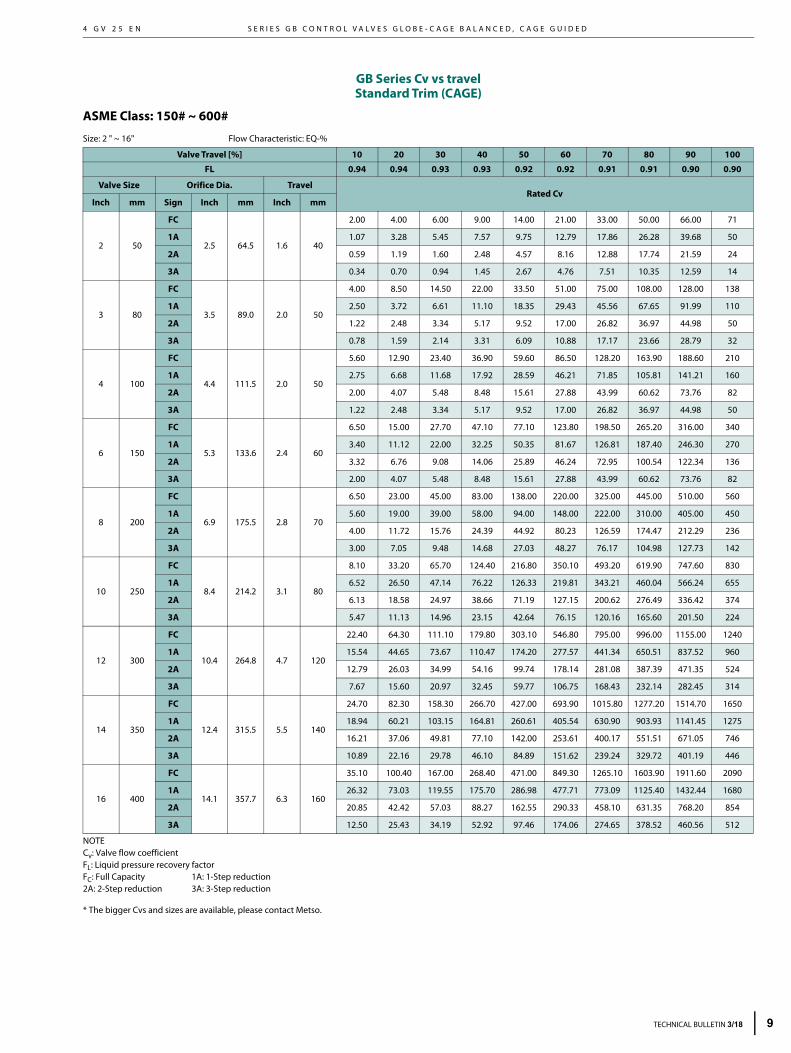
GB Series Cv vs travelStandard Trim (CAGE)
ASME Class: 150# ~ 600#
Size: 2 " ~ 16" Flow Characteristic: EQ-%
NOTECv: Valve flow coefficientFL: Liquid pressure recovery factorFC: Full Capacity 1A: 1-Step reduction2A: 2-Step reduction 3A: 3-Step reduction
* The bigger Cvs and sizes are available, please contact Metso.
Valve Travel [%] 10 20 30 40 50 60 70 80 90 100
FL 0.94 0.94 0.93 0.93 0.92 0.92 0.91 0.91 0.90 0.90
Valve Size Orifice Dia. TravelRated Cv
Inch mm Sign Inch mm Inch mm
2 50
FC
2.5 64.5 1.6 40
2.00 4.00 6.00 9.00 14.00 21.00 33.00 50.00 66.00 71
1A 1.07 3.28 5.45 7.57 9.75 12.79 17.86 26.28 39.68 50
2A 0.59 1.19 1.60 2.48 4.57 8.16 12.88 17.74 21.59 24
3A 0.34 0.70 0.94 1.45 2.67 4.76 7.51 10.35 12.59 14
3 80
FC
3.5 89.0 2.0 50
4.00 8.50 14.50 22.00 33.50 51.00 75.00 108.00 128.00 138
1A 2.50 3.72 6.61 11.10 18.35 29.43 45.56 67.65 91.99 110
2A 1.22 2.48 3.34 5.17 9.52 17.00 26.82 36.97 44.98 50
3A 0.78 1.59 2.14 3.31 6.09 10.88 17.17 23.66 28.79 32
4 100
FC
4.4 111.5 2.0 50
5.60 12.90 23.40 36.90 59.60 86.50 128.20 163.90 188.60 210
1A 2.75 6.68 11.68 17.92 28.59 46.21 71.85 105.81 141.21 160
2A 2.00 4.07 5.48 8.48 15.61 27.88 43.99 60.62 73.76 82
3A 1.22 2.48 3.34 5.17 9.52 17.00 26.82 36.97 44.98 50
6 150
FC
5.3 133.6 2.4 60
6.50 15.00 27.70 47.10 77.10 123.80 198.50 265.20 316.00 340
1A 3.40 11.12 22.00 32.25 50.35 81.67 126.81 187.40 246.30 270
2A 3.32 6.76 9.08 14.06 25.89 46.24 72.95 100.54 122.34 136
3A 2.00 4.07 5.48 8.48 15.61 27.88 43.99 60.62 73.76 82
8 200
FC
6.9 175.5 2.8 70
6.50 23.00 45.00 83.00 138.00 220.00 325.00 445.00 510.00 560
1A 5.60 19.00 39.00 58.00 94.00 148.00 222.00 310.00 405.00 450
2A 4.00 11.72 15.76 24.39 44.92 80.23 126.59 174.47 212.29 236
3A 3.00 7.05 9.48 14.68 27.03 48.27 76.17 104.98 127.73 142
10 250
FC
8.4 214.2 3.1 80
8.10 33.20 65.70 124.40 216.80 350.10 493.20 619.90 747.60 830
1A 6.52 26.50 47.14 76.22 126.33 219.81 343.21 460.04 566.24 655
2A 6.13 18.58 24.97 38.66 71.19 127.15 200.62 276.49 336.42 374
3A 5.47 11.13 14.96 23.15 42.64 76.15 120.16 165.60 201.50 224
12 300
FC
10.4 264.8 4.7 120
22.40 64.30 111.10 179.80 303.10 546.80 795.00 996.00 1155.00 1240
1A 15.54 44.65 73.67 110.47 174.20 277.57 441.34 650.51 837.52 960
2A 12.79 26.03 34.99 54.16 99.74 178.14 281.08 387.39 471.35 524
3A 7.67 15.60 20.97 32.45 59.77 106.75 168.43 232.14 282.45 314
14 350
FC
12.4 315.5 5.5 140
24.70 82.30 158.30 266.70 427.00 693.90 1015.80 1277.20 1514.70 1650
1A 18.94 60.21 103.15 164.81 260.61 405.54 630.90 903.93 1141.45 1275
2A 16.21 37.06 49.81 77.10 142.00 253.61 400.17 551.51 671.05 746
3A 10.89 22.16 29.78 46.10 84.89 151.62 239.24 329.72 401.19 446
16 400
FC
14.1 357.7 6.3 160
35.10 100.40 167.00 268.40 471.00 849.30 1265.10 1603.90 1911.60 2090
1A 26.32 73.03 119.55 175.70 286.98 477.71 773.09 1125.40 1432.44 1680
2A 20.85 42.42 57.03 88.27 162.55 290.33 458.10 631.35 768.20 854
3A 12.50 25.43 34.19 52.92 97.46 174.06 274.65 378.52 460.56 512
TECHNICAL BULLETIN 3/18 9
M E T S O
1
4 G V 2 5 E N
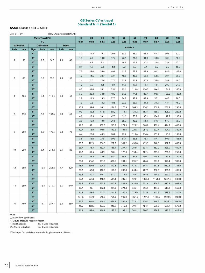
GB Series CV vs travelStandard Trim (Tendril 1)
ASME Class: 150# ~ 600#
Size: 2 " ~ 24" Flow Characteristic: LINEAR
NOTECv: Valve flow coefficientFL: Liquid pressure recovery factorFC: Full Capacity 1A: 1-Step reduction2A: 2-Step reduction 3A: 3-Step reduction
* The larger Cvs and sizes are available, please contact Metso.
Valve Travel [%] 10 20 30 40 50 60 70 80 90 100
FL 0.84 0.84 0.85 0.85 0.85 0.86 0.87 0.87 0.95 0.86
Valve Size Orifice Dia. TravelRated Cv
Inch mm Sign Inch mm Inch mm
2 50
FT
2.5 64.5 1.6 40
3.0 11.8 19.7 26.6 33.2 39.0 43.8 47.7 50.8 52.0
1T 1.9 7.7 13.0 17.7 22.4 26.8 31.0 34.8 38.3 40.0
2T 1.2 4.8 8.1 11.2 14.3 17.2 20.1 22.8 25.4 27.0
3T 0.4 1.7 2.9 4.0 5.2 6.3 7.4 8.5 9.6 10.0
3 80
FT
3.5 89.0 2.0 50
7.5 23.0 36.9 49.9 61.9 73.2 82.9 91.2 98.0 102.0
1T 4.7 14.6 23.7 32.4 40.6 48.8 56.4 63.6 70.4 75.0
2T 2.4 7.6 12.4 17.1 21.7 26.2 30.5 34.8 38.9 40.0
3T 1.2 3.9 6.4 8.9 11.3 13.8 16.1 18.4 20.7 21.0
4 100
FT
4.4 111.5 2.0 50
8.5 32.6 55.1 75.9 95.6 113.8 130.5 144.6 156.2 160.0
1T 5.3 20.4 34.8 48.3 61.5 74.1 86.7 98.5 109.6 120.0
2T 2.9 11.3 19.5 27.3 34.9 42.4 49.9 57.1 64.2 70.0
3T 1.9 7.6 13.2 18.5 23.8 28.9 34.2 39.2 44.1 46.0
6 150
FT
5.3 133.6 2.4 60
13.8 54.4 95.1 134.3 170.9 204.3 234.1 259.9 281.9 290.0
1T 9.0 35.2 61.8 88.2 114.1 139.2 163.1 185.7 206.9 220.0
2T 4.9 18.9 33.1 47.3 61.6 75.9 90.1 104.1 117.9 130.0
3T 2.9 10.8 18.8 26.9 35.0 43.2 51.4 59.5 67.7 75.0
8 200
FT
6.9 175.5 2.8 70
19.7 87.1 152.3 213.7 271.5 323.2 368.8 409.4 444.2 460.0
1T 12.7 56.0 98.8 140.5 181.6 220.5 257.3 292.4 324.9 340.0
2T 6.4 28.0 49.5 70.8 92.4 113.6 134.4 155.2 175.5 195.0
3T 3.6 15.6 27.5 39.3 51.4 63.3 75.1 87.1 99.0 105.0
10 250
FT
8.4 214.2 3.1 80
39.7 122.6 206.9 287.7 361.2 430.8 493.5 548.0 597.7 630.0
1T 25.7 78.3 132.7 186.4 237.5 288.4 337.1 382.2 426.0 460.0
2T 14.2 41.5 69.9 98.4 126.0 154.4 182.4 209.4 236.8 255.0
3T 8.4 23.2 38.6 54.1 69.1 84.6 100.2 115.3 130.8 140.0
12 300
FT
10.4 264.8 4.7 120
76.8 216.1 351.6 478.6 594.1 696.7 786.2 863.1 928.4 980.0
1T 48.9 136.8 224.6 310.8 394.0 473.3 548.1 617.8 682.3 735.0
2T 25.2 68.8 112.8 156.8 200.8 244.4 287.5 330.0 371.7 405.0
3T 15.4 40.7 66.1 91.7 117.4 143.1 168.8 194.5 220.0 240.0
14 350
FT
12.4 315.5 5.5 140
89.2 275.6 460.6 634.1 789.1 929.1 1050.3 1151.4 1237.4 1300.0
1T 56.5 174.0 293.5 410.7 521.9 629.9 731.6 824.7 912.3 985.0
2T 29.7 90.1 152.1 214.2 274.8 336.1 396.5 454.9 513.1 565.0
3T 16.4 48.4 81.3 114.3 146.8 179.9 212.9 245.3 278.2 310.0
16 400
FT
14.1 357.7 6.3 160
121.6 332.6 546.9 756.9 949.0 1121.7 1274.6 1402.5 1508.5 1580.0
1T 73.6 198.0 326.6 458.4 586.9 712.2 834.3 948.3 1055.2 1145.0
2T 41.5 108.3 177.2 248.6 319.8 391.4 464.1 535.3 605.7 670.0
3T 26.9 68.0 110.1 153.6 197.1 241.1 286.2 330.8 375.6 415.0
0 TECHNICAL BULLETIN 3/18
S E R I E S G B C O N T R O L V A L V E S G L O B E - C A G E B A L A N C E D , C A G E G U I D E D4 G V 2 5 E N
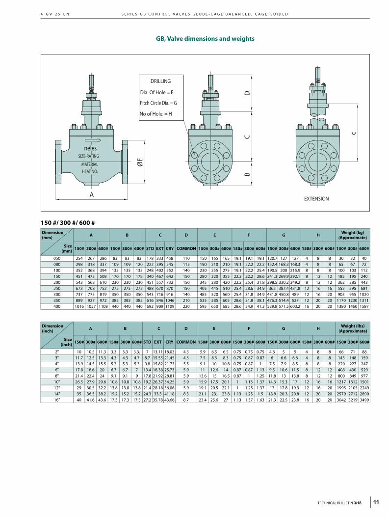
GB, Valve dimensions and weights
150 #/ 300 #/ 600 #Dimension (mm) A B C D E F G H Weight (kg)
(Approximate)
Size(mm) 150# 300# 600# 150# 300# 600# STD EXT CRY COMMON 150# 300# 600# 150# 300# 600# 150# 300# 600# 150# 300# 600# 150# 300# 600#
050 254 267 286 83 83 83 178 333 458 110 150 165 165 19.1 19.1 19.1 120.7 127 127 4 8 8 30 32 40080 298 318 337 109 109 120 222 395 545 115 190 210 210 19.1 22.2 22.2 152.4 168.3 168.3 4 8 8 65 67 72100 352 368 394 135 135 135 248 402 552 140 230 255 275 19.1 22.2 25.4 190.5 200 215.9 8 8 8 100 103 112150 451 473 508 170 170 178 340 467 642 150 280 320 355 22.2 22.2 28.6 241.3 269.9 292.1 8 12 12 185 195 240200 543 568 610 230 230 230 451 557 732 150 345 380 420 22.2 25.4 31.8 298.5 330.2 349.2 8 12 12 363 385 443250 673 708 752 275 275 275 488 670 870 150 405 445 510 25.4 28.6 34.9 362 387.4 431.8 12 16 16 552 595 681300 737 775 819 350 350 350 543 716 916 140 485 520 560 25.4 31.8 34.9 431.8 450.8 489 12 16 20 905 955 1020350 889 927 972 385 385 385 616 846 1046 210 535 585 605 28.6 31.8 38.1 476.3 514.4 527 12 20 20 1170 1230 1311400 1016 1057 1108 440 440 440 692 909 1109 220 595 650 685 28.6 34.9 41.3 539.8 571.5 603.2 16 20 20 1380 1460 1587
Dimension (inch) A B C D E F G H Weight (lbs)
(Approximate)
Size(inch) 150# 300# 600# 150# 300# 600# STD EXT CRY COMMON 150# 300# 600# 150# 300# 600# 150# 300# 600# 150# 300# 600# 150# 300# 600#
2" 10 10.5 11.3 3.3 3.3 3.3. 7 13.11 18.03 4.3 5.9 6.5 6.5 0.75 0.75 0.75 4.8 5 5 4 8 8 66 71 883" 11.7 12.5 13.3 4.3 4.3 4.7 8.7 15.55 21.45 4.5 7.5 8.3 8.3 0.75 0.87 0.87 6 6.6 6.6 4 8 8 143 148 1594" 13.9 14.5 15.5 5.3 5.3 5.3 9.8 15.82 21.73 5.5 9.1 10 10.8 0.75 0.87 1 7.5 7.9 8.5 8 8 8 220 227 2476" 17.8 18.6 20 6.7 6.7 7 13.4 18.38 25.73 5.9 11 12.6 14 0.87 0.87 1.13 9.5 10.6 11.5 8 12 12 408 430 5298" 21.4 22.4 24 9.1 9.1 9 17.8 21.92 28.81 5.9 13.6 15 16.5 0.87 1 1.25 11.8 13 13.8 8 12 12 800 849 977
10" 26.5 27.9 29.6 10.8 10.8 10.8 19.2 26.37 34.25 5.9 15.9 17.5 20.1 1 1.13 1.37 14.3 15.3 17 12 16 16 1217 1312 150112" 29 30.5 32.2 13.8 13.8 13.8 21.4 28.18 36.06 5.9 19.1 20.5 22.1 1 1.25 1.37 17 17.8 19.3 12 16 20 1995 2105 224914" 35 36.5 38.2 15.2 15.2 15.2 24.3 33.3 41.18 8.3 21.1 23. 23.8 1.13 1.25 1.5 18.8 20.3 20.8 12 20 20 2579 2712 289016" 40 41.6 43.6 17.3 17.3 17.3 27.2 35.78 43.66 8.7 23.4 25.6 27 1.13 1.37 1.63 21.3 22.5 23.8 16 20 20 3042 3219 3499
DRILLING
No of Hole. = H
Dia. Of Hole = F
Pitch Circle Dia. = G
BC
ØE
EXTENSION
neles
A
D
c
MATERIALHEAT NO.
SIZE-RATING
TECHNICAL BULLETIN 3/18 11
M E T S O
1
4 G V 2 5 E N
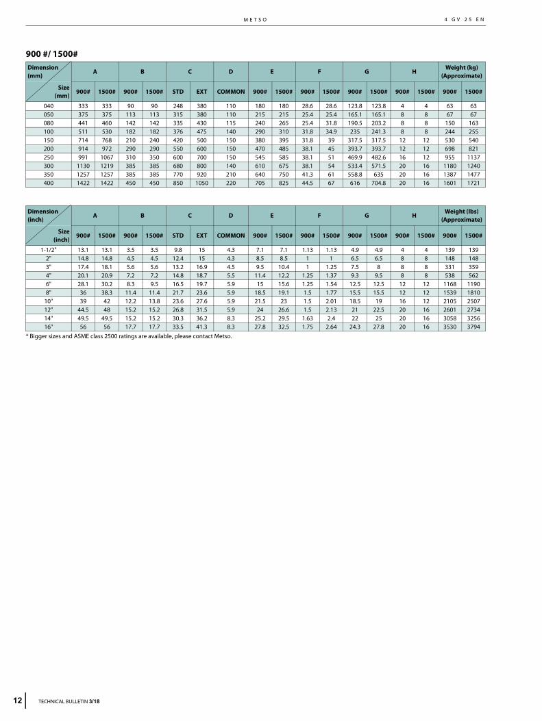
900 #/ 1500#
* Bigger sizes and ASME class 2500 ratings are available, please contact Metso.
Dimension (mm)
A B C D E F G HWeight (kg)
(Approximate)
Size(mm)
900# 1500# 900# 1500# STD EXT COMMON 900# 1500# 900# 1500# 900# 1500# 900# 1500# 900# 1500#
040 333 333 90 90 248 380 110 180 180 28.6 28.6 123.8 123.8 4 4 63 63050 375 375 113 113 315 380 110 215 215 25.4 25.4 165.1 165.1 8 8 67 67080 441 460 142 142 335 430 115 240 265 25.4 31.8 190.5 203.2 8 8 150 163100 511 530 182 182 376 475 140 290 310 31.8 34.9 235 241.3 8 8 244 255150 714 768 210 240 420 500 150 380 395 31.8 39 317.5 317.5 12 12 530 540200 914 972 290 290 550 600 150 470 485 38.1 45 393.7 393.7 12 12 698 821250 991 1067 310 350 600 700 150 545 585 38.1 51 469.9 482.6 16 12 955 1137300 1130 1219 385 385 680 800 140 610 675 38.1 54 533.4 571.5 20 16 1180 1240350 1257 1257 385 385 770 920 210 640 750 41.3 61 558.8 635 20 16 1387 1477400 1422 1422 450 450 850 1050 220 705 825 44.5 67 616 704.8 20 16 1601 1721
Dimension (inch)
A B C D E F G HWeight (lbs)
(Approximate)
Size(inch)
900# 1500# 900# 1500# STD EXT COMMON 900# 1500# 900# 1500# 900# 1500# 900# 1500# 900# 1500#
1-1/2" 13.1 13.1 3.5 3.5 9.8 15 4.3 7.1 7.1 1.13 1.13 4.9 4.9 4 4 139 1392" 14.8 14.8 4.5 4.5 12.4 15 4.3 8.5 8.5 1 1 6.5 6.5 8 8 148 1483" 17.4 18.1 5.6 5.6 13.2 16.9 4.5 9.5 10.4 1 1.25 7.5 8 8 8 331 3594" 20.1 20.9 7.2 7.2 14.8 18.7 5.5 11.4 12.2 1.25 1.37 9.3 9.5 8 8 538 5626" 28.1 30.2 8.3 9.5 16.5 19.7 5.9 15 15.6 1.25 1.54 12.5 12.5 12 12 1168 11908" 36 38.3 11.4 11.4 21.7 23.6 5.9 18.5 19.1 1.5 1.77 15.5 15.5 12 12 1539 1810
10" 39 42 12.2 13.8 23.6 27.6 5.9 21.5 23 1.5 2.01 18.5 19 16 12 2105 250712" 44.5 48 15.2 15.2 26.8 31.5 5.9 24 26.6 1.5 2.13 21 22.5 20 16 2601 273414" 49.5 49.5 15.2 15.2 30.3 36.2 8.3 25.2 29.5 1.63 2.4 22 25 20 16 3058 325616" 56 56 17.7 17.7 33.5 41.3 8.3 27.8 32.5 1.75 2.64 24.3 27.8 20 16 3530 3794
2 TECHNICAL BULLETIN 3/18
S E R I E S G B C O N T R O L V A L V E S G L O B E - C A G E B A L A N C E D , C A G E G U I D E D4 G V 2 5 E N
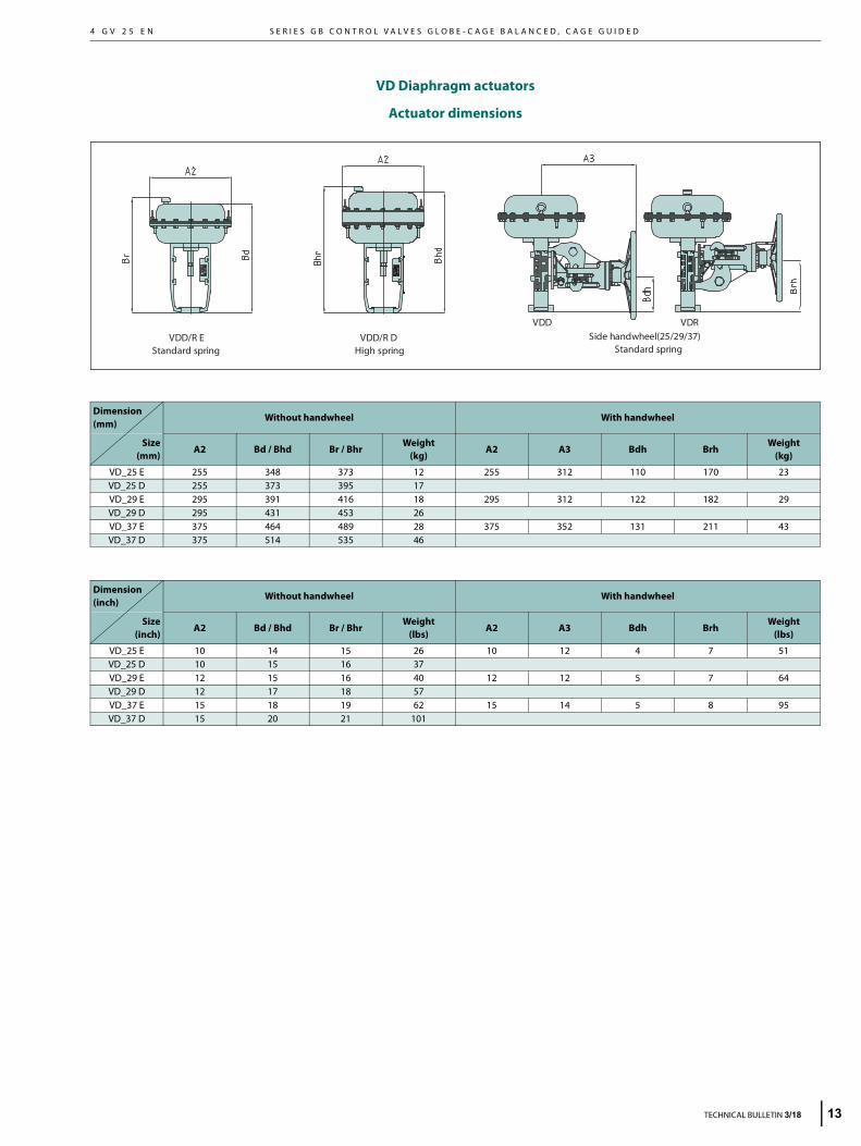
VD Diaphragm actuators
Actuator dimensions
Dimension (mm)
Without handwheel With handwheel
Size(mm)
A2 Bd / Bhd Br / BhrWeight
(kg)A2 A3 Bdh Brh
Weight(kg)
VD_25 E 255 348 373 12 255 312 110 170 23VD_25 D 255 373 395 17VD_29 E 295 391 416 18 295 312 122 182 29VD_29 D 295 431 453 26VD_37 E 375 464 489 28 375 352 131 211 43VD_37 D 375 514 535 46
Dimension (inch)
Without handwheel With handwheel
Size(inch)
A2 Bd / Bhd Br / BhrWeight
(lbs)A2 A3 Bdh Brh
Weight(lbs)
VD_25 E 10 14 15 26 10 12 4 7 51VD_25 D 10 15 16 37VD_29 E 12 15 16 40 12 12 5 7 64VD_29 D 12 17 18 57VD_37 E 15 18 19 62 15 14 5 8 95VD_37 D 15 20 21 101
Standard spring High spring Standard springVDD/R E VDD/R D Side handwheel(25/29/37)
VDD VDR
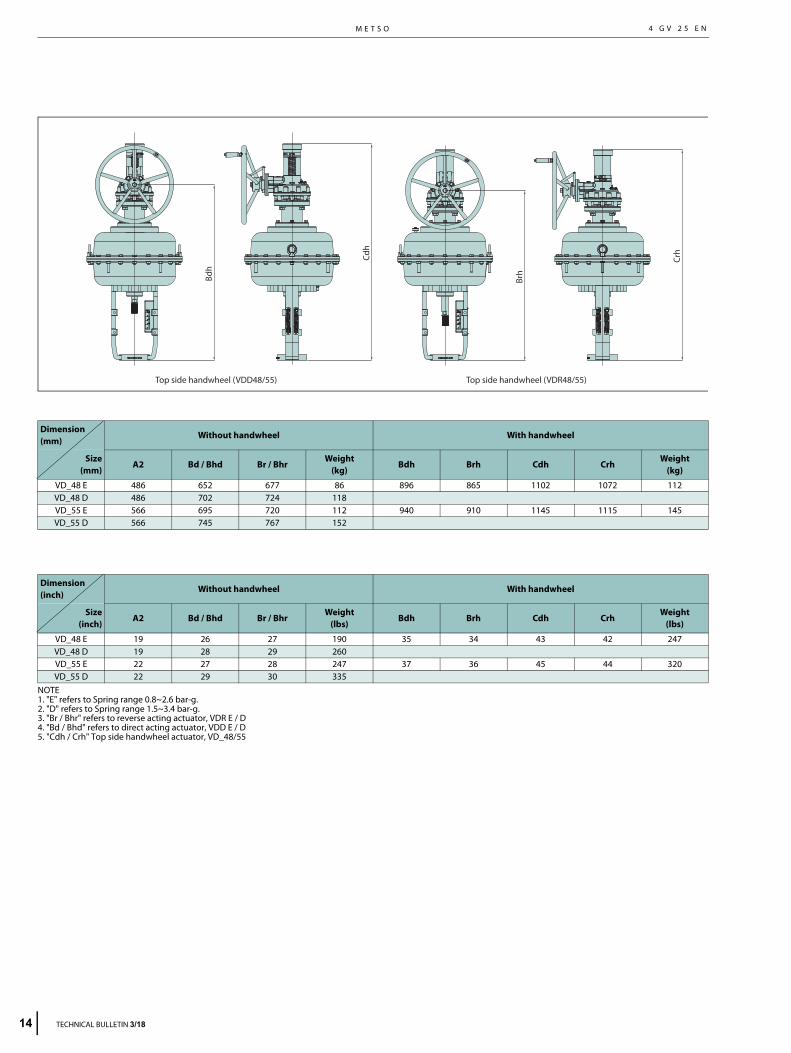
TECHNICAL BULLETIN 3/18 13
M E T S O
1
4 G V 2 5 E N
4 TECHNICAL BULLETIN 3/18
NOTE1. "E" refers to Spring range 0.8~2.6 bar-g.2. "D" refers to Spring range 1.5~3.4 bar-g.3. "Br / Bhr" refers to reverse acting actuator, VDR E / D4. "Bd / Bhd" refers to direct acting actuator, VDD E / D5. "Cdh / Crh" Top side handwheel actuator, VD_48/55
Dimension (mm)
Without handwheel With handwheel
Size(mm)
A2 Bd / Bhd Br / BhrWeight
(kg)Bdh Brh Cdh Crh
Weight(kg)
VD_48 E 486 652 677 86 896 865 1102 1072 112VD_48 D 486 702 724 118VD_55 E 566 695 720 112 940 910 1145 1115 145VD_55 D 566 745 767 152
Dimension (inch)
Without handwheel With handwheel
Size(inch)
A2 Bd / Bhd Br / BhrWeight
(lbs)Bdh Brh Cdh Crh
Weight(lbs)
VD_48 E 19 26 27 190 35 34 43 42 247VD_48 D 19 28 29 260VD_55 E 22 27 28 247 37 36 45 44 320VD_55 D 22 29 30 335
Top side handwheel (VDD48/55) Top side handwheel (VDR48/55)
Bdh
Brh
Cdh
Crh
S E R I E S G B C O N T R O L V A L V E S G L O B E - C A G E B A L A N C E D , C A G E G U I D E D4 G V 2 5 E N
Actuator dimensions
VC cylinder actuators without handwheel
VC actuators without handwheel
VC actuators without handwheel
VC, without volume chamber VC, with volume chamber
BA
B1
B2
ØC
ØC
Stroke(mm)
#30 #40 #50 ØC 370 ØC 460 ØC 560B1 Weight (kg) B1 Weight (kg) B1 Weight (kg)B2 A B B2 A B B2 A B
40 640 92 115 810 120 148 810 186 234760 935 935
50 650 94 118 820 123 152 820 189 237790 965 965
60 660 97 121 830 126 155 830 192 242820 995 995
70 670 100 124 840 128 159 840 195 246850 1025 1025
80 680 103 127 850 131 162 850 198 251880 1055 1055
90 690 106 130 860 134 166 860 201 256910 1085 1085
100 700 108 133 870 137 173 870 203 261940 1115 1115
120 720 114 139 890 142 177 890 209 2701000 1175 1175
140 910 148 184 910 215 2791235 1235
180 950 159 198 950 227 2981355 1355
Stroke (mm)
#60 #70 #80ØC 660 ØC 710 ØC 820B1 Weight(kg) B1 Weight(kg) B1 Weight(kg)B2 A B B2 A B B2 A B
100 954 255 344 955 322 438 954 378 5191199 1203 1207
120 974 262 355 975 330 450 974 386 5311259 1263 1267
140 994 269 365 995 338 461 994 394 5431319 1323 1327
180 1034 283 386 1035 354 484 1034 410 5671439 1443 1447
240 1094 303 417 1095 377 518 1094 435 6041619 1623 1627
280 1134 451 6281747
Stroke (mm)
#30 #40 #50ØC 15 ØC 18 ØC 22B1 Weight (lbs) B1 Weight (lbs) B1 Weight (lbs)B2 A B B2 A B B2 A B
40 25 203 254 32 265 326 32 410 51630 37 37
50 26 207 260 32 271 335 32 417 52231 38 38
60 26 214 267 33 278 342 33 423 53432 39 39
70 26 220 273 33 282 351 33 430 54233 40 40
80 27 227 280 33 289 357 33 437 55335 42 42
90 27 234 287 34 295 366 34 443 56436 43 43
100 28 238 293 34 302 381 34 448 57537 44 44
120 28 251 306 35 313 390 35 461 59539 46 46
140 36 326 406 36 474 61549 49
180 37 351 437 37 500 65753 53
Stroke (mm)
#60 #70 #80ØC 26 ØC 28 ØC 32B1 Weight(lbs) B1 Weight(lbs) B1 Weight(lbs)B2 A B B2 A B B2 A B
100 38 562 758 38 710 966 37 833 114447 47 48
120 38 578 783 38 728 992 38 851 117150 50 50
140 39 593 805 39 745 1016 39 869 119752 52 52
180 41 624 851 41 780 1067 41 904 125057 57 57
240 43 668 919 43 831 1142 43 959 133264 64 64
280 45 994 138569
TECHNICAL BULLETIN 3/18 15
M E T S O
1
4 G V 2 5 E N
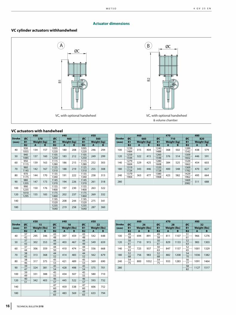
Actuator dimensions
VC cylinder actuators withhandwheel
VC actuators with handwheel
& volume chamberVC, with optional handwheel VC, with optional handwheel
BA
B2
ØCØC
B1
Stroke(mm)
#30 #40 #50 ØC 370 ØC 460 ØC 560B1 Weight (kg) B1 Weight (kg) B1 Weight (kg)B2 A B B2 A B B2 A B
40 930 134 157 1095 180 208 1095 246 2941055 1220 1220
50 940 137 160 1105 183 212 1105 249 2991085 1250 1250
60 950 139 163 1115 186 215 1115 252 3031115 1280 1280
70 960 142 167 1125 188 219 1125 255 3081145 1310 1310
80 970 144 170 1135 191 222 1135 258 3131175 1340 1340
90 980 147 173 1145 194 226 1145 261 3181205 1370 1370
100 990 150 176 1155 197 230 1155 263 3221235 1400 1400
120 1010 155 183 1175 202 237 1175 269 3321295 1460 1460
140 1195 208 244 1195 275 3411520 1520
180 1235 219 258 1235 287 3601640 1640
Stroke (mm)
#60 #70 #80ØC 660 ØC 710 ØC 820B1 Weight (kg) B1 Weight (kg) B1 Weight (kg)B2 A B B2 A B B2 A B
100 1239 315 404 1240 368 502 1289 438 5791484 1488 1542
120 1259 322 415 1260 376 514 1309 446 5911544 1548 1602
140 1279 329 425 1280 384 525 1329 454 6031604 1608 1662
180 1319 343 446 1320 400 548 1369 470 6271724 1728 1782
240 1379 363 477 1380 423 582 1429 495 6641904 1908 1962
280 1469 511 6882082
Stroke(mm)
#30 #40 #50ØC 15 ØC 18 ØC 22B1 Weight (lbs) B1 Weight (lbs) B1 Weight (lbs)B2 A B B2 A B B2 A B
40 37 295 346 43 397 459 43 542 64842 48 48
50 37 302 353 44 403 467 44 549 65943 49 49
60 37 306 359 44 410 474 44 556 66844 50 50
70 38 313 368 44 414 483 44 562 67945 52 52
80 38 317 375 45 421 489 45 569 69046 53 53
90 39 324 381 45 428 498 45 575 70147 54 54
100 39 331 388 45 434 507 45 580 71049 55 55
120 40 342 403 46 445 522 46 593 73251 57 57
140 47 459 538 47 606 75260 60
180 49 483 569 49 633 79465 65
Stroke (mm)
#60 #70 #80ØC 26 ØC 28 ØC 32B1 Weight (lbs) B1 Weight (lbs) B1 Weight (lbs)B2 A B B2 A B B2 A B
100 49 694 891 49 811 1107 51 966 127658 58 61
120 50 710 915 50 829 1133 52 983 130361 61 63
140 50 725 937 50 847 1157 52 1001 132963 63 65
180 52 756 983 52 882 1208 54 1036 138268 68 70
240 54 800 1052 54 933 1283 56 1091 146475 75 77
280 58 1127 151782
6 TECHNICAL BULLETIN 3/18
S E R I E S G B C O N T R O L V A L V E S G L O B E - C A G E B A L A N C E D , C A G E G U I D E D
7
4 G V 2 5 E N
TECHNICAL BULLETIN 3/18 1
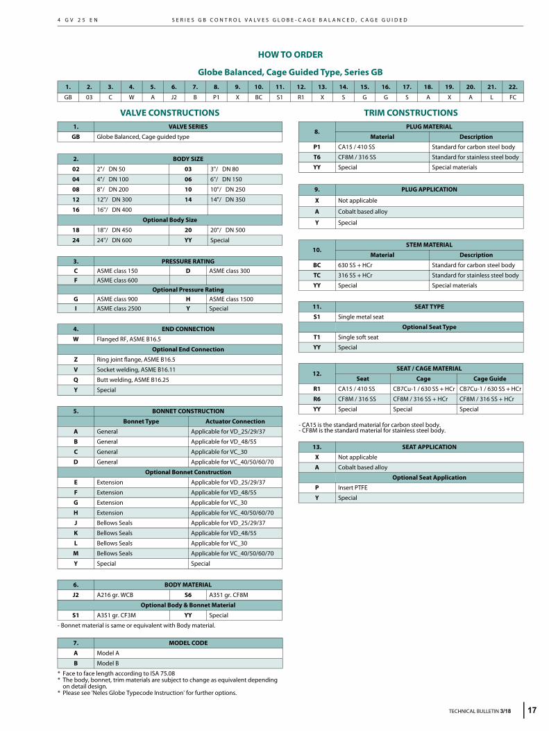
HOW TO ORDER
Globe Balanced, Cage Guided Type, Series GB
VALVE CONSTRUCTIONS
- Bonnet material is same or equivalent with Body material.
* Face to face length according to ISA 75.08* The body, bonnet, trim materials are subject to change as equivalent depending
on detail design.* Please see 'Neles Globe Typecode Instruction' for further options.
TRIM CONSTRUCTIONS
- CA15 is the standard material for carbon steel body.- CF8M is the standard material for stainless steel body.
1. 2. 3. 4. 5. 6. 7. 8. 9. 10. 11. 12. 13. 14. 15. 16. 17. 18. 19. 20. 21. 22.
GB 03 C W A J2 B P1 X BC S1 R1 X S G G S A X A L FC
1. VALVE SERIES
GB Globe Balanced, Cage guided type
2. BODY SIZE
02 2"/ DN 50 03 3"/ DN 80
04 4"/ DN 100 06 6"/ DN 150
08 8"/ DN 200 10 10"/ DN 250
12 12"/ DN 300 14 14"/ DN 350
16 16"/ DN 400
Optional Body Size
18 18"/ DN 450 20 20"/ DN 500
24 24"/ DN 600 YY Special
3. PRESSURE RATINGC ASME class 150 D ASME class 300F ASME class 600
Optional Pressure RatingG ASME class 900 H ASME class 1500I ASME class 2500 Y Special
4. END CONNECTION
W Flanged RF, ASME B16.5
Optional End Connection
Z Ring joint flange, ASME B16.5
V Socket welding, ASME B16.11
Q Butt welding, ASME B16.25
Y Special
5. BONNET CONSTRUCTION
Bonnet Type Actuator Connection
A General Applicable for VD_25/29/37
B General Applicable for VD_48/55
C General Applicable for VC_30
D General Applicable for VC_40/50/60/70
Optional Bonnet Construction
E Extension Applicable for VD_25/29/37
F Extension Applicable for VD_48/55
G Extension Applicable for VC_30
H Extension Applicable for VC_40/50/60/70
J Bellows Seals Applicable for VD_25/29/37
K Bellows Seals Applicable for VD_48/55
L Bellows Seals Applicable for VC_30
M Bellows Seals Applicable for VC_40/50/60/70
Y Special Special
6. BODY MATERIAL
J2 A216 gr. WCB S6 A351 gr. CF8M
Optional Body & Bonnet Material
S1 A351 gr. CF3M YY Special
7. MODEL CODE
A Model A
B Model B
8.PLUG MATERIAL
Material Description
P1 CA15 / 410 SS Standard for carbon steel body
T6 CF8M / 316 SS Standard for stainless steel body
YY Special Special materials
9. PLUG APPLICATION
X Not applicable
A Cobalt based alloy
Y Special
10.STEM MATERIAL
Material Description
BC 630 SS + HCr Standard for carbon steel body
TC 316 SS + HCr Standard for stainless steel body
YY Special Special materials
11. SEAT TYPE
S1 Single metal seat
Optional Seat Type
T1 Single soft seat
YY Special
12.SEAT / CAGE MATERIAL
Seat Cage Cage Guide
R1 CA15 / 410 SS CB7Cu-1 / 630 SS + HCr CB7Cu-1 / 630 SS + HCr
R6 CF8M / 316 SS CF8M / 316 SS + HCr CF8M / 316 SS + HCr
YY Special Special Special
13. SEAT APPLICATION
X Not applicable
A Cobalt based alloy
Optional Seat Application
P Insert PTFE
Y Special
M E T S O
1
4 G V 2 5 E N
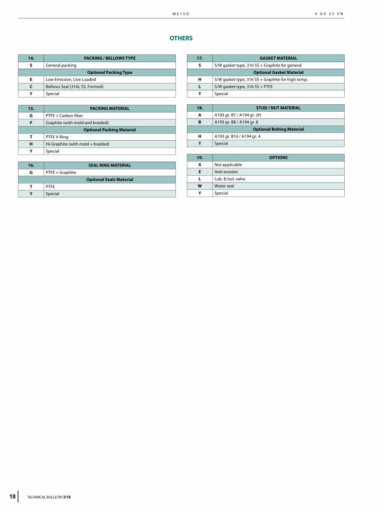
OTHERS
14. PACKING / BELLOWS TYPE
S General packing
Optional Packing Type
E Low Emission, Live Loaded
C Bellows Seal (316L SS, Formed)
Y Special
15. PACKING MATERIAL
G PTFE + Carbon fiber
F Graphite (with mold and braided)
Optional Packing Material
T PTFE V-Ring
H Hi-Graphite (with mold + braided)
Y Special
16. SEAL RING MATERIAL
G PTFE + Graphite
Optional Seals Material
T PTFE
Y Special
17. GASKET MATERIAL
S S/W gasket type, 316 SS + Graphite for general
Optional Gasket Material
H S/W gasket type, 316 SS + Graphite for high temp.
L S/W gasket type, 316 SS + PTFE
Y Special
18. STUD / NUT MATERIAL
A A193 gr. B7 / A194 gr. 2H
B A193 gr. B8 / A194 gr. 8
Optional Bolting Material
H A193 gr. B16 / A194 gr. 4
Y Special
19. OPTIONS
X Not applicable
E Anti-erosion
L Lub. & Isol. valve
W Water seal
Y Special
8 TECHNICAL BULLETIN 3/18

S E R I E S G B C O N T R O L V A L V E S G L O B E - C A G E B A L A N C E D , C A G E G U I D E D4 G V 2 5 E N
TRIM TYPE & RATED Cv
- Rated Cv is different by the trim type and characteristic. - Srk means valve stroke in mm.
20.
TRIM TYPE
21.TRIM
CHARACTERISTIC
22. RATED Cv
Sign Sign Sign DescriptionBody Size and Stroke
2" Srk. 3" Srk. 4" Srk. 6" Srk. 8" Srk. 10" Srk. 12" Srk. 14" Srk. 16" Srk.
A General plug type L Linear FC General /
Full capacity 74 (40) 142 (50) 230 (50) 380 (60) 600 (70) 950 (80) 1270 (120) 1740 (140) 2215 (160)
P Pilot balanced plug type 1A General /
1-Step reduction 48 (40) 98 (50) 160 (50) 275 (60) 455 (70) 700 (80) 970 (120) 1300 (140) 1530 (160)
2A General / 2-Step reduction 26 (40) 56 (50) 86 (50) 150 (60) 254 (70) 398 (80) 550 (120) 776 (140) 940 (160)
3A General / 3-Step reduction 16 (40) 34 (50) 52 (50) 90 (60) 152 (70) 238 (80) 340 (120) 464 (140) 568 (160)
FT Tendril 1 / Full capacity 52 (40) 102 (50) 160 (50) 290 (60) 460 (70) 630 (80) 980 (120) 1300 (140) 1580 (160)
1T Tendril 1 / 1-Step reduction 40 (40) 42 (50) 120 (50) 220 (60) 340 (70) 460 (80) 735 (120) 985 (140) 1145 (160)
2T Tendril 1 / 2-Step reduction 27 (40) 10 (50) 70 (50) 130 (60) 195 (70) 255 (80) 405 (120) 565 (140) 670 (160)
3T Tendril 1 / 3-Step reduction 10 (40) 21 (50) 46 (50) 75 (60) 105 (70) 140 (80) 240 (120) 310 (140) 410 (160)
FM Tendril 2 / Full capacity 50 (40) 100 (50) 155 (50) 280 (60) 425 (70) 590 (80) 920 (120) 1240 (140) 1530 (160)
1M Tendril 2 / 1-Step reduction 35 (40) 74 (50) 115 (50) 215 (60) 330 (70) 450 (80) 720 (120) 970 (140) 1130 (160)
2M Tendril 2 / 2-Step reduction 23 (40) 33 (50) 65 (50) 12 (60) 190 (70) 240 (80) 380 (120) 550 (140) 640 (160)
3M Tendril 2 / 3-Step reduction 8 (40) 18 (50) 38 (50) 67 (60) 100 (70) 130 (80) 220 (120) 290 (140) 390 (160)
E Equal % FC General / Full capacity 71 (40) 138 (50) 210 (50) 340 (60) 560 (70) 830 (80) 1240 (120) 1650 (140) 2090 (160)
1A General / 1-Step reduction 50 (40) 110 (50) 160 (50) 270 (60) 450 (70) 655 (80) 960 (120) 1275 (140) 1680 (160)
2A General / 2-Step reduction 24 (40) 50 (50) 82 (50) 136 (60) 236 (70) 374 (80) 524 (120) 746 (140) 854 (160)
3A General / 3-Step reduction 14 (40) 32 (50) 50 (50) 82 (60) 142 (70) 224 (80) 314 (120) 446 (140) 512 (160)
FT Tendril 1 / Full capacity 50 (40) 82 (50) 135 (50) 235 (60) 370 (70) 500 (80) 840 (120) 1110 (140) 1400 (160)
1T Tendril 1 / 1-Step reduction 35 (40) 58 (50) 95 (50) 170 (60) 265 (70) 370 (80) 600 (120) 785 (140) 1020 (160)
2T Tendril 1 / 2-Step reduction 20 (40) 35 (50) 58 (50) 100 (60) 170 (70) 225 (80) 355 (120) 480 (140) 600 (160)
3T Tendril 1 / 3-Step reduction 10 (40) 20 (50) 32 (50) 58 (60) 105 (70) 125 (80) 205 (120) 290 (140) 350 (160)
FM Tendril 2 / Full capacity 47 (40) 74 (50) 130 (50) 230 (60) 330 (70) 470 (80) 770 (120) 1050 (140) 1320 (160)
1M Tendril 2 / 1-Step reduction 33 (40) 56 (50) 92 (50) 165 (60) 245 (70) 330 (80) 570 (120) 720 (140) 960 (160)
2M Tendril 2 / 2-Step reduction 19 (40) 33 (50) 52 (50) 95 (60) 145 (70) 190 (80) 330 (120) 430 (140) 550 (160)
3M Tendril 2 / 3-Step reduction 8 (40) 16 (50) 25 (50) 52 (60) 80 (70) 110 (80) 190 (120) 270 (140) 295 (160)
Y Special Y Special YY Special Contact Metso for Cv details
TECHNICAL BULLETIN 3/18 19

Metso Corporation Töölönlahdenkatu 2, PO Box 1220, 00100 Helsinki, FinlandTel. +358 20 484 100
Metso Flow Control Inc.Vanha Porvoontie 229, P.O. Box 304, FI-01301 VANTAA, Finland.Tel. +358 20 483 150. Fax +358 20 483 151
www.metso.com/valves
Subject to change without prior notice. Product names in thisbulletin are all trademarks of Metso Flow Control Inc.