series lfii residential sprinkler design guide table of ...aasprink.com/files/tfp490_01_2006.pdf ·...
TRANSCRIPT

Table ofContentsSECTIONS
General . . . . . . . . . . . . . . 1
Design — Background . . . . . 1
Design — Hydraulics . . . . . . 2
Design — Sprinkler Location . 3
Design — Beam Ceilings . . . 16
Installation . . . . . . . . . . . 18
Care and Maintenance . . . . 18
Limited Warranty . . . . . . . 18
TABLES
Series LFIIResidential Sprinklers . . . . . 1
Rise over Run ConversionTo Degrees of Slope . . . . . . 3
FIGURES
Spacing Under HorizontalCeilings (Parts 1 and 2) . . . . 4-5
Spacing Under SlopedCeilings (Parts 1 thru 7) . . 6-11
Spacing To AvoidObstructions . . . . . . . . . . 12
Positioning Of SprinklersWith Respect ToObstructions Along Walls . . 13
Proximity To HeatSources (Parts 1 and 2) . . 14-15
Beam Ceilings . . . . . . . 16-18
GeneralTyco Fire Products’ (TFP) ResidentialSprinklers are fast response automaticsprinklers. They are to be used only inwet pipe residential sprinkler systemsfor one- and two-family dwellings andmobile homes per NFPA 13D; wet piperesidential sprinkler systems for resi-dential occupancies up to and includ-ing four stories in height per NFPA13R; or, wet pipe sprinkler systems forthe residential portions of any occu-pancy per NFPA 13.
This document provides design guid-ance for the Series LFII ResidentialSprinklers outlined in Table A.
Residential fire sprinkler systems
should only be designed and installedby those competent and completelyfamiliar with automatic sprinkler sys-tem design, installation procedures,and techniques. Several criteria mayapply to a given installation and usageof each sprinkler. Consequently, thesprinkler system designer is recom-mended to review and develop a work-ing understanding of the complete listof criteria prior to initiating the designof a residential fire sprinkler system.
WARNINGSThe Series LFII Residential Sprinklersdescribed herein must be installed andmaintained in compliance with thisdocument, as well as with the applica-ble standards of the National Fire Pro-
Page 1 of 20 TFP490JANUARY, 2006
SPRINKLER/MODELIDENTIFICATION
NUMBERTYPE
TECHNICALDATA SHEET
NUMBER
TY2234
TY1334
TY2284
TY2596
Pendent andRecessed Pendent, K=4.9
Horizontal Sidewall andRecessed Horizontal, K=4.2
FlushPendent, K=4.2
Concealed PendentFlat Plate, K=4.2
TFP400
TFP410
TFP420
TFP440
TABLE A, SERIES LFII RESIDENTIAL SPRINKLERS
TY3334 Horizontal Sidewall andRecessed Horizontal, K=5.6
TFP415
TY2384 FlushHorizontal Sidewall, K=4.2
TFP425
TY2234 Concealed PendentDomed Plate, K=4.9
TFP450
TY3596 Concealed PendentFlat Plate, K=4.9
TFP442
TY4234 Pendent, Recessed,and Concealed Pendent, K=6.9
TFP408
Series LFIIResidential SprinklerDesign Guide
Technical Services: Tel: (800) 381-9312 / Fax: (800) 791-5500

tection Association, in addition to thestandards of any other authorities hav-ing jurisdiction. Failure to do so mayimpair the performance of these de-vices.
The owner is responsible for maintain-ing their fire protection system and de-vices in proper operating condition.The installing contractor or sprinklermanufacturer should be contactedwith any questions.
Design —BackgroundThe design criteria for ResidentialSprinklers begins with the Third Edi-tion of Underwriters Laboratories Inc.UL 1626 dated July 10, 2001 —“Standard for Residential Sprinklersfor Fire Protection Service”. All TFPResidential Sprinklers are tested andlisted under UL 1626 with specific pub-lished spacings, flows, and pressuresfor each residential sprinkler identifiedby its sprinkler/model identificationnumber and as detailed in the Techni-cal Data Sheets referenced in Table A.
One of the most notable revisions in-corporated into the Third Edition of UL1626 is the new minimum flow ratesthat are effective for product manufac-tured after July 12, 2002, which is in-tended for installation in new systems.When establishing a flow rate for ULListing, the manufacturer must use aminimum required discharge that cor-relates to a 0.05 gpm/ft2. Due to wallwetting requirements, the under-standing is that the density applied atthe floor will be less than 0.05 gpm/ft2.Also, the understanding in some casesis that the UL Listed flow rate may begreater than the calculated 0.05gpm/ft2 to be able to successfully passthe UL 1626 fire tests. Increased flowrates for sidewall type sprinklers iscommon.
The design criteria for residentialsprinklers contained in the currentNFPA Standards must be followed ex-cept as modified by the individual UL1626 listing information provided in theTechnical Data Sheets referenced inTable A and this design guide.
NOTEThe approval of all residential sprinklerdesigns and installations must bemade by the Authority Having Jurisdic-tion (AHJ) for compliance with all gov-ernmental codes and standards.
Design —HydraulicsNFPA13D. The number of designsprinklers shall include all sprinklerswithin a compartment up to a maxi-mum of two sprinklers where specificUL Listed flows are provided. Theminimum required sprinkler flow ratefor systems designed to NFPA 13D aregiven in the Technical Data Sheetsreferenced in Table A, as a function oftemperature rating and the maximumallowable coverage areas. For actualcoverage areas less than or betweenthose indicated in the Technical DataSheets referenced in Table A, it is nec-essary to use the minimum requiredflow for the next largest coverage area.
Example No. 1: Assuming the use of apendent sprinkler, the actual coveragearea being protected is 14 ft. x 16 ft. Inthis case the minimum flow require-ment for a 16 ft. x 16 ft. coverage areamust be used.
Example No. 2: Assuming the use of apendent sprinkler, the actual coveragearea being protected is 17 ft. x 17 ft. Inthis case the minimum flow require-ment for a 18 ft. x 18 ft. coverage areamust be used.
NFPA13R. The number of designsprinklers shall include all sprinklerswithin a compartment up to a maxi-mum of four sprinklers where specificUL Listed flows are provided. Theminimum required sprinkler flow ratefor systems designed to NFPA 13R aregiven in the Technical Data Sheetsreferenced in Table A, as a function oftemperature rating and the maximumallowable coverage areas. For actualcoverage areas less than or betweenthose indicated in the Technical DataSheets referenced in Table A, it is nec-essary to use the minimum requiredflow for the next largest coverage area.
Example No. 1: Assuming the use of apendent sprinkler, the actual coveragearea being protected is 14 ft. x 16 ft. Inthis case the minimum flow require-ment for a 16 ft. x 16 ft. coverage areamust be used.
Example No. 2: Assuming the use of apendent sprinkler, the actual coveragearea being protected is 17 ft. x 17 ft. Inthis case the minimum flow require-ment for a 18 ft. x 18 ft. coverage areamust be used.
NFPA 13. The number of design sprin-klers is to be the the four most hydrau-lically demanding sprinklers. The mini-mum required discharge from each ofthe four sprinklers is to be the greaterof the following:
• The flow rates given in the TechnicalData Sheets referenced in Table Afor NFPA 13D and 13R as a functionof temperature rating and the maxi-mum allowable coverage area. Foractual coverage areas less than orbetween those indicated in theTechnical Data Sheets referenced inTable A, it is necessary to use theminimum required flow for the nextlargest coverage area.
• A minimum discharge of 0.1 gpm/sq.ft. over the “design area” comprisedof the four most hydraulically de-manding sprinklers for the actualcoverage areas being protected bythe four sprinklers. The greatest di-mension of the actual coverage areacannot be any greater than the maxi-mum coverage areas indicated inthe Technical Data Sheets refer-enced in Table A.
Example No.1: A corridor being pro-tected is 8 ft. wide; consequently, anactual coverage area of 8 ft. x 20 ft. isbeing contemplated. Based on usingthe LFII (TY2234) Pendent ResidentialPendent Sprinkler, the flow rate pro-vided in TFP400 for a 20 ft x 20 ft.coverage area is 20 GPM. Howeverbased on minimum discharge of 0.1gpm/sq. ft. the flow rate would be 16GPM. In this case a minimum flow rateof 20 GPM for this design sprinklermust be utilized.
Example No.2: A long narrow roombeing protected is 12 ft. wide; conse-quently, an actual coverage area of 12ft. x 20 ft. is being contemplated.Based on using the LFII (TY2234)Pendent Residential Pendent Sprin-kler, the flow rate provided in TFP400for a 20 ft x 20 ft. coverage area is 20GPM. However based on minimumdischarge of 0.1 gpm/sq. ft. the flowrate would be 24 GPM. In this case aminimum flow rate of 24 GPM for thisdesign sprinkler must be utilized.
Compartment. A compartment is aspace that is completely enclosed bywalls and a ceiling. The compartmentenclosure may have openings to anadjoining space, provided the open-ings have a minimum lintel depth of 8inches from the ceiling.
Sloped Ceilings. For systems de-signed to NFPA 13, 13D, or 13R andwhere specific UL Listed flows havenot been provided for sloped ceilings,consult with the local Authority HavingJurisdiction with regard to the numberof “design sprinklers” for sloped ceil-ings having a slope greater than a 2inch rise for a 12 inch run.
Page 2 of 20 TFP490

Design —SprinklerLocationWhen locating Residential Sprinklers,Sprinkler Spacing, Obstruction ToWater Distribution, Heat Sensitivity,Preventing Cold Soldering, and Prox-imity To A Heat Source must all beconsidered.
Table B provides a conversion of “RiseOver Run” that is a conventionalmethod of defining slope in architec-tural drawings to “Degrees Of Slope”as used in this guideline.
Sprinkler Spacing Under HorizontalCeilings (Up to 9 degrees of slope).Residential sprinklers are utilized forvarious maximum spacings in accord-ance with minimum flows and pres-sures. Typical coverage areas for pen-dent sprinklers are 12 ft. x 12 ft. up to20 ft. x 20 ft., and typical coverageareas for horizontal sidewall sprinklersare 12 ft. x 12 ft. up to 16 ft. x 20 ft.Refer to the Technical Data Sheetsreferenced in Table A for coverageareas, and refer to Figure 1 for Spac-ing Rules Under Horizontal Ceil-ings. Understanding the intendedarea of coverage while using this guideis critical.
Always remember that the spacing of
sprinklers under horizontal ceilingswith slopes greater than 0 degrees(i.e., non-level) is measured along theslope when determining distance off ofwalls and between sprinklers.
Sprinkler Spacing Under SlopedCeilings (10 to a 60 degrees ofslope). Residential sprinklers are util-ized for various maximum spacings inaccordance with minimum flows andpressures. Typical coverage areas forpendent sprinklers are 12 ft. x 12 ft. upto 20 ft. x 20 ft., and typical coverageareas for horizontal sidewall sprinklersare 12 ft. x 12 ft. up to 16 ft. x 20 ft.Refer to the Technical Data Sheetsreferenced in Table A for coverageareas, and refer to Figure 2 for Spac-ing Rules Under Sloped Ceilings.Understanding the intended area ofcoverage while using this guide is criti-cal.
Always remember that the spacing ofsprinklers under sloped ceilings ismeasured along the slope when deter-mining distance off of walls and be-tween sprinklers.
Obstruction To Water Distribution.Location with respect to obstructionsto water distribution are addressed byFigure 3. If a sprinkler water distribu-tion pattern is obstructed, the obstruc-tion is to be considered the maximumdistance of coverage for a given sprin-kler and additional sprinklers beyondthe obstruction will be necessary.
Because of the varied nature of resi-dential type construction, there will besome compartment designs that can-not be fully sprinklered in accordancewith the recommendations of NFPA13, 13D, or 13R. In the event of thiscondition, consult with the AuthorityHaving Jurisdiction.
Appendix material in NFPA 13D and13R references the evaluation of cer-tain small areas.
Small areas created by architecturalfeatures such as planter box windows,bay windows, and similar features canbe evaluated as follows:
(a) Where no additional floor spacearea is created by the architecturalfeature, no additional sprinkler protec-tion is required.
(b) Where additional floor space is cre-ated by an architectural feature, noadditional sprinkler protection is re-quired, provided all of the followingconditions are met:
• The floor area does not exceed 18sq. ft.
• The floor area is not greater than 2ft. in depth at the deepest point of thearchitectural feature to the plane ofthe primary wall where measuredalong the finished floor.
• The floor is not greater than 9 ft. inlength where measured along theplane of the primary wall.
Measurement from the the deepestpoint of the architectural feature to thesprinkler should not exceed the maxi-mum listed spacing of the sprinkler.The hydraulic design is not required toconsider the area created by the archi-tectural feature.
Figure 4 provides guidance for posi-tioning of pendent and horizontal side-wall sprinklers with respect to obstruc-tions along a wall, and in the case ofpendent sprinklers the positioning ofsprinklers on both sides of a continu-ous obstruction located at the ceiling.Consideration must be given to thesize of the obstruction, as well as theallowable deflector-to ceiling distance.
Heat Sensitivity. Sensitivity to heat iscritical for prompt operation of a resi-dential sprinkler for a fire condition.The Technical Data Sheets referencedin Table A provide the allowable sprin-kler deflector-to-ceiling distances.
Residential sprinklers are to be in-stalled beneath smooth flat ceilings asdefined by NFPA 13.
NOTESpecial consideration, such as in-creasing the number of design sprin-klers being hydraulically calculated,
TFP490 Page 3 of 20
TABLE BRISE OVER RUN CONVERSION TO DEGREES OF SLOPE
1 2 3 4 5 6 7 8 9 10 11RUN, INCHES
12
45°
RIS
E,I
NC
HE
S 8
7
6
5
3
4
2
1
11
12
10
9
27° 18° 14° 11° 9° 8° 7° 6° 6° 5° 5°
45° 34° 27° 22° 18° 16° 14° 13° 11° 10° 9°
56° 45° 37° 31° 27° 23° 21° 18° 17° 15° 14°
63° 45° 39° 34° 30° 27° 24° 22° 20° 18°
59° 51° 45° 40° 36° 32° 29° 27° 24° 23°
56° 50° 45° 41° 37° 34° 31° 29° 27°
60° 54° 49° 45° 41° 38° 35° 32° 30°
58° 53° 49° 45° 42° 39° 36° 34°
56° 52° 48° 45° 42° 39° 37°
59° 55° 51° 48° 45° 42° 40°
58° 54° 51° 48° 45° 42°
60° 56° 53° 50° 46° 45°

must be given to installations wherecontinuous obstructions to heat floware present (e.g., beams, lintels, etc.).
Under a sloped ceiling, the residentialsprinkler(s) located at the highest ele-vation must not be located more than3 feet measured vertically down fromthe peak.
Preventing Cold Solder. A minimumdistance between residential sprin-klers to prevent cold soldering (i.e.,the wetting from an operated sprinkleronto an unoperated sprinkler thatcould prevent its potential to operate ifneeded) must be maintained.
Under horizontal ceilings, the mini-
mum distance between residentialsprinklers to prevent cold soldering is8 feet.
Sloped ceilings, however, presentmore of a cause for concern for coldsoldering, since the elevation of onesprinkler may be higher than another,resulting in a different distribution pat-tern than that of a horizontal ceilingcondition. Figure 2 for Spacing RulesUnder Sloped Ceilings addresses theminimum acceptable distance undervarious sloped ceiling conditions thatwill take into account the prevention ofcold soldering.
One solution to prevent cold soldering
is to stagger the sprinklers so that thedistance between two sprinklers is in-creased. In some case, baffles can belocated midway between two closelylocated sprinklers to prevent cold sol-dering.
Proximity To A Heat Source. Sprin-klers must be located so as to preventan inadvertent operation due to expo-sure of normal heat sources. Locationwith respect to exposure of heatsources other than fire that may causean inadvertent operation of a residen-tial sprinkler is addressed by Figure 5.
Page 4 of 20 TFP490
FIGURE 1 — PART 1 of 2SPRINKLER SPACING UNDER HORIZONTAL CEILINGS
— SIDEWALL SPRINKLER —
NOTE
Sidewall sprinklers, where installed under a ceiling with a slope greater than 0 degrees to 9 degrees, must be locatedper one of the following:
• Locate the sprinklers at the high point of the slope and positioned to discharge down the slope.
• Locate the sprinklers along the slope and positioned to discharge across the slope.
AB
AB
PLAN 1J
A -
E
A A
CC
CD
PLAN 1K
BA
B
C
A
E
D
BA
BA
C
PLAN 1L
BA
B
C
C
A
BA
BA
E
PLAN 1M
B
E
AB
C
A
BACKWALL
BACKWALL
BACKWALL
WALLBACK
BACKWALL
UP TO ONE HALF THEMAXIMUM SPRINKLERSPACING (SEE
MINIMUM 4".
TECHNICAL DATA
B -
C -
IN TABLE A) FOR THESHEETS REFERENCED
COVERAGE AREA BEINGHYDRAULICALLYCALCULATED.
COVERAGE AREA BEINGIN TABLE A) FOR THESHEETS REFERENCED
SPRINKLER WIDTHUP TO THE MAXIMUM
CALCULATED.HYDRAULICALLY
(SEE TECHNICAL DATA
D - MINIMUM 8'-0".
E -
COVERAGE AREA BEINGIN TABLE A) FOR THESHEETS REFERENCED
SPRINKLER LENGTHUP TO THE MAXIMUM
CALCULATED.HYDRAULICALLY
(SEE TECHNICAL DATA
SIDEWALL SPRINKLER.

TFP490 Page 5 of 20
FIGURE 1 — PART 2 of 2SPRINKLER SPACING UNDER HORIZONTAL CEILINGS
— PENDENT SPRINKLERS —
PLAN 1H
PLAN 1E
PLAN 1B
A
PLAN 1F
D
BA D
AB
CD
BA
D
A
BA
A
A
B
A
AB
AB
B
BA
B
AB
PLAN 1A
BA A
B
(TYP)90°
AB
AB
A
DC
AB
B
B
AB
AB
A
CD
A
B
A
B
PENDENT SPRINKLER.
MINIMUM 8'-0".
UP TO ONE HALF THEMAXIMUM SPRINKLERSPACING (SEE
MINIMUM 4".
TECHNICAL DATA
D -
B -
A -
C -A
CD
AB
B
AB
IN TABLE A) FOR THESHEETS REFERENCED
PLAN 1C PLAN 1D
BA
BB
PLAN 1G
A
A
AB
COVERAGE AREA BEINGHYDRAULICALLYCALCULATED.
COVERAGE AREA BEINGIN TABLE A) FOR THESHEETS REFERENCED
SPRINKLER SPACINGUP TO THE MAXIMUM
CALCULATED.HYDRAULICALLY
(SEE TECHNICAL DATA

FIGURE 2 — PART 1 of 6SPRINKLER SPACING UNDER SLOPED CEILINGS
— MULTIPLE SPRINKLERS ON SAME SLOPE AND DISTANCE OFF WALLS —
Page 6 of 20 TFP490
10° - 60° CEILING ANGLE.
ONE HALF THE MAXIMUM SPRINKLER SPACING(SEE TECHNICAL DATA SHEETS REFERENCED
B -
A -
IN TABLE A) FOR THE COVERAGE AREA BEING
MAXIMUM:
MAXIMUM:
RANGE:
E
PENDENT SPRINKLERS
A
D
SIDEWALL SPRINKLERS
TECHNICAL DATA SHEETS REFERENCED INTHE MAXIMUM SPRINKLER SPACING (SEE
HYDRAULICALLY CALCULATED.8'-0"MINIMUM:
3'-0"C - MAXIMUM:
D -
E - MINIMUM: 4"
A
B
E
C
D
E E
C
A
B
A
ELEVATION
BACK WALL
ELEVATION
HYDRAULICALLY CALCULATED.
TABLE A) FOR THE COVERAGE AREA BEING

FIGURE 2 — PART 2 of 6SPRINKLER SPACING UNDER SLOPED CEILINGS
— SYMMETRIC SPRINKLER LOCATIONS ON OPPOSING SLOPES —
TFP490 Page 7 of 20
PENDENT SPRINKLERS SIDEWALL SPRINKLERS
E - MINIMUM: 8'-0"
E
D
A
D
A
B
C
D
A
E
B
A
D
C
10° - 60° CEILING ANGLE.RANGE:
3'-0"C - MAXIMUM:
D -
ELEVATION
BACKWALL
ONE HALF THE MAXIMUM SPRINKLER SPACING(SEE TECHNICAL DATA SHEETS REFERENCED
B -
A -
IN TABLE A) FOR THE COVERAGE AREA BEING
MAXIMUM:
MAXIMUM:TECHNICAL DATA SHEETS REFERENCED INTHE MAXIMUM SPRINKLER SPACING (SEE
HYDRAULICALLY CALCULATED.8'-0"MINIMUM:
HYDRAULICALLY CALCULATED.
TABLE A) FOR THE COVERAGE AREA BEING
ELEVATION

FIGURE 2 — PART 3 of 6SPRINKLER SPACING UNDER SLOPED CEILINGS
SPRINKLERS LOCATED ON INTERSECTING HORIZONTAL AND SLOPE CEILINGS —
Page 8 of 20 TFP490
(a)
(b)
(d)
(c)
CEILING ANGLE 'C', DEGREES(°)
3'-0" WHEN THERE ARE NO SPRINKLERS ON
10° - 60° CEILING ANGLE.
3
2
0
SLA
NT
DIS
TAN
CE
,
MIN
IMU
MR
EQ
UIR
ED
MIN
IMU
M
DIS
TAN
CE
, FE
ET
HO
RIZ
ON
TAL
RE
QU
IRE
D
010
1
3
2
FE
ET
15 20
GRAPH B
25 30 35 40
ACCEPTABLE
4
5
6
1
10 15
GRAPH A
20 25 30 35
D -
C -
B -
A -
PENDENT SPRINKLERS
C
D
PERGRAPH
A
A
THE LEVEL CEILING
MAXIMUM:
MAXIMUM:
RANGE:
MINIMUM: 8'-0"
D
B
C C
A
BGRAPH
PER
45 50 55 60
UNACCEPTABLE
40 45 50 55 60
SIDEWALL SPRINKLERS
D D
C
GRAPHPER
A
A
B
A
B
PERGRAPH
ELEVATION ELEVATION
BACKWALL
CEILING ANGLE 'C', DEGREES(°)
ONE HALF THE MAXIMUM SPRINKLER SPACING(SEE TECHNICAL DATA SHEETS REFERENCEDIN TABLE A) FOR THE COVERAGE AREA BEINGHYDRAULICALLY CALCULATED.
SPACING(SEE TECHNICAL
HYDRAULICALLYCALCULATED:
SPRINKLER
REFERENCED IN
(a) 20'(b)
(d)(d)
(c) 16'14'12'
18'
DATA SHEETS
TABLE A) BEING
A
A
A
A

TFP490 Page 9 of 20
FIGURE 2 — PART 4 of 6SPRINKLER SPACING UNDER SLOPED CEILINGS
— NON-SYMMETRIC SPRINKLER LOCATIONS ON OPPOSING SLOPES —
USE THE GREATER OF ANGLE 'C' OR ANGLE 'D'
10° - 45° CEILING ANGLE.
35
CEILING ANGLE, DEGREES(°)
10° - 45° CEILING ANGLE.
D -
E -
C -
B -
A -
1510 2520
(a)
30
(b)(c)
3'-0"MAXIMUM:
RANGE:
RANGE:
MINIMUM: 8'-0"
MAXIMUM:
45
(d)
(e)
40
MIN
IMU
M
FE
ET
RE
QU
IRE
DS
LAN
TD
ISTA
NC
E,
1
2
3
4
5
E
PENDENT SPRINKLERS
C D C
SIDEWALL SPRINKLERS
E
D
SPACING(SEE TECHNICAL
HYDRAULICALLYCALCULATED:
SPRINKLER
REFERENCED IN
(a) 20'(b)
(d)(e)
(c) 16'14'12'
18'
GRAPH A
ELEVATION
BACKWALL
B
PERGRAPH
A
A
GRAPHPER
A
B
A
ONE HALF THE MAXIMUM SPRINKLER SPACING(SEE TECHNICAL DATA SHEETS REFERENCEDIN TABLE A) FOR THE COVERAGE AREA BEINGHYDRAULICALLY CALCULATED.
ELEVATION
DATA SHEETS
TABLE A) BEING
A A

Page 10 of 20 TFP490
FIGURE 2 — PART 5 of 6SPRINKLER SPACING UNDER SLOPED CEILINGS—PENDENT SPRINKLERS LOCATED AT PEAK —
UNACCEPTABLE
CEILING ANGLE 'C', DEGREES(°)
10° - 60° CEILING ANGLE.
PENDENT SPRINKLERS
D -
C -
ACCEPTABLE
10 15 20 4025 30 35
MINIMUM: 8'-0"
RANGE:
C
A
BB
605545 50
A
C
HO
RIZ
ON
TAL
MA
XIM
UM
PE
RM
ITT
ED
DIS
TAN
CE
'B',
FE
ET
7
5
3
4
6
8
9
10
D D
GRAPH A
ONE HALF THE MAXIMUM SPRINKLER SPACING(SEE TECHNICAL DATA SHEETS REFERENCED
B -
A -
IN TABLE A) FOR THE COVERAGE AREA BEING
MAXIMUM:
MAXIMUM:SPACING (SEE TECHNICAL DATA SHEETSUP TO ONE HALF THE MAXIMUM SPRINKLER
AREA BEING HYDRAULICALLY CALCULATED OR
HYDRAULICALLY CALCULATED.
REFERENCED IN TABLE A) FOR THE COVERAGE
ELEVATION
AS RESTRICTED BY GRAPH A.

TFP490 Page 11 of 20
FIGURE 2 — PART 6 of 6SPRINKLER SPACING UNDER SLOPED CEILINGS—SIDEWALL SPRINKLERS LOCATED AT PEAK —
B -
SIDEWALL SPRINKLERS
10° - 45° CEILING ANGLE.RANGE:
A - MAXIMUM:AREA LENGTH (SEE TECHNICAL DATA SHEETSUP TO THE MAXIMUM SPRINKLER COVERAGE
AREA BEING HYDRAULICALLY CALCULATED.REFERENCED IN TABLE A) FOR THE COVERAGE
ELEVATION
A
B

Page 12 of 20 TFP490
FIGURE 3 — PART 1 of 2PENDENT SPRINKLER POSITIONING TO AVOID OBSTRUCTION TO WATER DISTRIBUTION
RADIALLY FROM THE PENDENT SPRINKLER
V VGRAPH A GRAPH A
DISTANCE 'H' TO OBSTRUCTION, FEET
0
6
12
18
30 1 2
GRAPH A
4 5 6 87 9 10
GRAPH AV
GRAPH AV
GRAPH AH
GRAPH AH
HGRAPH A
GRAPH AH
TO
OB
ST
RU
CT
ION
,D
ISTA
NC
E'V
'
INC
HE
SELEVATION
PLAN OF SPRINKLER COVERAGE LENGTH, FEET
0
*TO TOP OF
GRAPH A
GRAPH AGRAPH A GRAPH AV V
GRAPH A GRAPH A
GRAPH A
GRAPH A
V
V
GRAPH A
* * *
*
BACKWALL
WALLBACK
H H H
H
ELEVATION
2 4 6 8 10 12 14 16 18 20
BA
CK
WA
LL,F
EE
TD
ISTA
NC
E'H
' ALO
NG
0
2
4
6
8
SIDEWALLSPRINKLER
NO OBSTRUCTIONS 1"
V =
11"2" 3" 4" 9" 14"5" 6" 7"
DEFLECTOR
FIGURE 3 — PART 2 of 2SIDEWALL SPRINKLER POSITIONING TO AVOID OBSTRUCTION TO WATER DISTRIBUTION
TO THE SIDE AND TO THE FRONT OF THE SIDEWALL SPRINKLER

FIGURE 4 — PART 1 of 2POSITIONING OF PENDENT SPRINKLERS
WITH RESPECT TO OBSTRUCTIONS ALONG A WALL OR CONTINUOUS OBSTRUCTIONS AT THE CEILINGTO AVOID OBSTRUCTION TO WATER DISTRIBUTION
TFP490 Page 13 of 20
CEILINGOBSTRUCTION
SPRINKLERS DO NOT EXCEED
PROVIDING THE DISTANCEEXCEEDING 4 FEET IN WIDTH
SPRINKLER SPACING "A"
SIDES OF AN OBSTRUCTION NOTBE LOCATED ON OPPOSITEPENDENT SPRINKLERS MAY
(SEE TECHNICAL DATASHEETS REFERENCED
THE OBSTRUCTION TO THEFROM THE CENTERLINE OF
ONE HALF THE MAXIMUM
IN TABLE A)
CEILINGOBSTRUCTION
D A
B
A (D - 8") + BD 30"
IN WIDTH ARE PERMITTEDTO BE PROTECTED WHEN
OR EQUAL TO 30 INCHESWHERE "D" IS LESS THANAGAINST THE WALL AND
OBSTRUCTIONS LOCATED
OR EQUAL TO "D"
PLUS "B"MINUS 8 INCHES
"A" IS GREATER THAN
WALL
ELEVATIONELEVATION
A A
FIGURE 4 — PART 2 of 2POSITIONING OF HORIZONTAL SIDEWALL SPRINKLERS
WITH RESPECT TO OBSTRUCTIONS ALONG A WALLTO AVOID OBSTRUCTION TO WATER DISTRIBUTION
MAXIMUM4 INCHES
MAXIMUM8 INCHES
CEILING
ELEVATION
SOFFIT
WALL
DEFLECTORSPRINKLER
TOP OF
(SEE TECHNICAL
REFERENCEDDATA SHEETS
CEILING DISTANCE
ALLOWABLE
CEILING
SOFFIT
DEFLECTORSPRINKLER
TOP OF
DEFLECTOR-TO-
IN TABLE A)
REFERENCEDDATA SHEETS
(SEE TECHNICAL
IN TABLE A)
CEILING DISTANCEDEFLECTOR-TO-
MAXIMUMDEFLECTOR-TO-
(SEE TECHNICALCEILING DISTANCE
REFERENCEDIN TABLE A)
DATA SHEETS
MINIMUM
WALL
ELEVATION
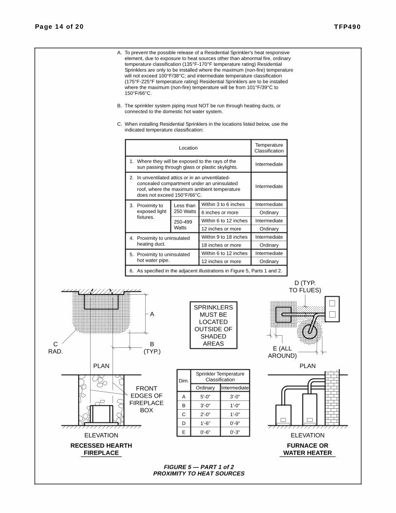
FIGURE 5 — PART 1 of 2PROXIMITY TO HEAT SOURCES
Page 14 of 20 TFP490
Where they will be exposed to the rays of thesun passing through glass or plastic skylights.
1.
In unventilated attics or in an unventilated-concealed compartment under an uninsulated
2.
roof, where the maximum ambient temperaturedoes not exceed 150°F/66°C.
3. Proximity toexposed lightfixtures.
Less than250 Watts
Within 3 to 6 inches
6 inches or more
Intermediate
Intermediate
Intermediate
Ordinary
250-499Watts
Within 6 to 12 inches
12 inches or more
Intermediate
Ordinary
4. Proximity to uninsulatedheating duct.
Within 9 to 18 inches
18 inches or more
Intermediate
Ordinary
5. Proximity to uninsulatedhot water pipe.
Within 6 to 12 inches
12 inches or more
Intermediate
Ordinary
6. As specified in the adjacent illustrations in Figure 5, Parts 1 and 2.
RECESSED HEARTHFIREPLACE
CRAD.
A
B(TYP.)
FRONTEDGES OFFIREPLACE
BOX
FURNACE ORWATER HEATER
E (ALLAROUND)
D (TYP.TO FLUES)
Ordinary Intermediate
5'-0" 3'-0"A
3'-0" 1'-0"B
2'-0" 1'-0"C
1'-6" 0'-9"D
0'-6" 0'-3"E
Sprinkler TemperatureClassification
ELEVATION ELEVATION
PLAN PLAN
LocationClassificationTemperature
To prevent the possible release of a Residential Sprinkler's heat responsiveelement, due to exposure to heat sources other than abnormal fire, ordinarytemperature classification (135°F-170°F temperature rating) ResidentialSprinklers are only to be installed where the maximum (non-fire) temperaturewill not exceed 100°F/38°C; and intermediate temperature classification(175°F-225°F temperature rating) Residential Sprinklers are to be installedwhere the maximum (non-fire) temperature will be from 101°F/39°C to
A.
150°F/66°C.
The sprinkler system piping must NOT be run through heating ducts, orconnected to the domestic hot water system.
B.
When installing Residential Sprinklers in the locations listed below, use theindicated temperature classification:
C.
SPRINKLERSMUST BELOCATED
OUTSIDE OFSHADEDAREAS
Dim.

FIGURE 5 — PART 2 of 2PROXIMITY TO HEAT SOURCES
TFP490 Page 15 of 20
COAL OR WOODBURNING STOVE
HRAD.
F
G(TYP.)
SIDES OFSTOVE
Ordinary Intermediate
3'-6" 1'-0"F
3'-6" 1'-0"G
3'-6" 1'-0"H
2'-0" 1'-0"J
2'-0" 1'-0"K
Sprinkler TemperatureClassification
ELEVATION
PLAN
WALL MOUNTEDHOT AIR DIFFUSER
PLAN
M(TYP.)
CEILING MOUNTEDHOT AIR DIFFUSER
PLAN
J(TYP.)
KRAD.
L
N(TYP.)
N(TYP.)
N(TYP.)
PRAD.
N(TYP.)
(TYP.) PRAD.(TYP.)
KITCHEN RANGE AND/OR OVEN
PLAN
3'-0" 1'-6"L
2'-0" 1'-0"M
1'-6" 0'-9"N
1'-6" 0'-9"P
SPRINKLERSMUST BELOCATED
OUTSIDE OFSHADEDAREAS
Dim.
PRAD.(TYP.) N
(TYP.)
N(TYP.)

Design —Beam CeilingsResidential occupancies with horizon-tal ceilings (i.e., slopes up to a 2 inchrise over a 12 inch run) with beamsmay be sprinklered as follows:
General Information. The basic con-cept of this protection scheme is tolocate the sprinklers on the undersideof the beams, Ref. Figure 6, (not in thebeam pockets); to identify the mainbeams that principally run in one direc-tion as “primary beams”; and, to iden-tify the beams that run principally per-pendicular to the main beams, as maybe present (or in some cases may benecessary for proper sprinkler protec-tion), as “secondary beams”.
Primary and Secondary BeamTypes. Solid surface, solid or hollowcore, combustible or non-combustible.
Primary and Secondary Beam Posi-tioning. Directly attached to the un-derside of a combustible or non-com-bustible smooth ceiling at anyelevation.
Primary Beam Cross-Section: Maxi-mum depth of 14 inches and the maxi-mum width is unlimited. The cross-sectional shape of the primary beammay be rectangular to circular.
Secondary Beam Cross-Section.Maximum depth to be no greater thanthe primary beam and the maximumwidth is unlimited. The cross-sectionalshape of the secondary beam may berectangular to circular.
Primary Beam Spacing. The primarybeams (Fig. 7A) are to be 3 ft. - 4 in. to6 ft. from the compartment wall tocenter of the nearest beam and fromcenter to center between beams.
Secondary Beam Spacing. The sec-ondary beams principally run perpen-dicular to the primary beams.
Secondary beams of a depth equal tothe primary beam must be placed sothat the beam pockets created by theprimary beams do not exceed 20 feetin length (Fig. 7B).
NOTEWhen the beam pockets created bythe primary beams exceed 20 feet inlength, the installation will require theuse of secondary beams as describedabove. Otherwise, secondary beamsneed not be present.
Secondary beams of a cross-sectionaldepth greater than one-quarter thedepth of the primary beams are to bea minimum of 3 ft. - 4 in. from thecompartment wall to center of the
nearest beam and from center to cen-ter between beams (Fig. 7C).
Secondary beams of a cross-sectionaldepth no greater than one-quarter thedepth of the primary beams may beplaced at any compartment wall tocenter of the nearest beam distanceand from any center to center distancebetween beams (Fig. 7C).
Lintels. Lintels over doorways exitingthe compartment must be present. Theminimum height for the lintels is 8inches or no less than the depth of thePrimary Beams, whichever is greater.
Sprinkler Types. Series LFII(TY2234), 155F and 175F, Pendentand Recessed Pendent ResidentialSprinklers; and, Series LFII (TY2284),162F, Flush Pendent ResidentialSprinklers.
Sprinkler Coverage Area and Hy-draulic Design. The sprinkler cover-age areas and hydraulic design criteriaas presented in Technical Data SheetsTF400 and TFP420 for “HorizontalCeilings” are to be applied.
Sprinkler Position. The deflector tobottom of primary beams for the SeriesLFII (TY2234) Pendent Sprinklers orSeries LFII (TY2234) Recessed Pen-dent Sprinklers is to be 1-1/4 to 1-3/4inches (Fig. 6A). The vertical center-line of the Series LFII (TY2234) Pen-dent Sprinklers is to be no greater thanhalf the primary beam cross-sectionalwidth plus 2 inches from the centerlineof the primary beam (Fig 6B).
The bottom of heat collector to bottomof primary beams for the Series LFII(TY2284) Flush Pendent Sprinklers isto be 23/32 to 1-3/32 inches (Fig. 6C).The vertical centerline of the SeriesLFII (TY2284) Flush Pendent Sprin-klers is to be no greater than half theprimary beam cross-sectional widthplus 2 inches from the centerline of theprimary beam (Fig. 6D).
NOTESCore drilling of beams to allow the in-stallation of sprinkler drops requiresconsulting with a structural engineer.
Where core drilling is not permitted,the previously stated sprinkler positioncriteria for the Series LFII (TY2234)Pendent Sprinklers allows for thesprinkler drop to be placed adjacent tothe primary beam.
Beam and Soffit Arrangements. Asoffit is permitted to be placed aroundthe perimeter of a compartment withthe beam arrangement within the sof-fited area (Fig.8).
The cross-section of the soffit may beany size as long as it does not createan obstruction to water distribution per
Page 16 of 20 TFP490
FIGURE 6SPRINKLER POSITIONING
UNDER BEAMS
C
ONE-HALF BEAMWIDTH PLUS2" (50,8 mm)
MAXIMUM
D
ONE-HALF BEAMWIDTH PLUS2" (50,8 mm)
MAXIMUM TY2234
TY2234
A
B
1-3/
4"(4
4,5
mm
)M
AX
.1-
1/4"
(31,
8m
m)
MIN
.1-
1/4"
(31,
8m
m)
MIN
.1-
3/4"
(44,
5m
m)
MA
X.
TY2284
23/3
2"(1
8,3
mm
)M
IN.
1-3/
32"
(27,
8m
m)
MA
X.
FLUSHPOSITIONTY2284
1-3/
32"
(27,
8m
m)
MA
X.
23/3
2"(1
8,3
mm
)M
IN.

FIGURE 7PERMITTED BEAM ARRANGEMENTS
TFP490 Page 17 of 20
SECONDARYBEAM
A AA
FIGURE 7APRIMARY BEAM SPANS UP TO 20'-0" (6,1 m)
FIGURE 7BPRIMARY BEAM SPANS GREATER THAN 20'-0" (6,1 m)
FIGURE 7CCOMBINATIONS OF PRIMARY AND SECONDARY BEAMS
B
A AA
A AA
B
C
C
FOR SECONDARY BEAMSTHAT ARE TO BE EQUAL INDEPTH TO PRIMARY BEAMSAND THAT MUST BE IN PLACESO THAT PRIMARY BEAMPOCKETS DO NOT EXCEED20'-0" (6,1 m)
SECONDARY BEAMS HAVINGDEPTHS GREATER THAN 25%OF PRIMARY BEAMS
B = 20'-0" (6,1 m) MAXIMUM
C = 3'-4" (1,0 m) MINIMUM FOR
or
A = 3'-4" to 6'-0" (1,0 to 1,8 m)FOR PRIMARY BEAMS HAV-
DEPTHING A 14" (356 mm) MAXIMUM
ONDARY BEAMS HAVINGDEPTHS UP TO 25% OFPRIMARY BEAMS
C = ANY DISTANCE FOR SEC-
A = 3'-4" to 6'-0" (1,0 to 1,8 m)FOR PRIMARY BEAMS HAV-
DEPTHING A 14" (356 mm) MAXIMUM
A = 3'-4" to 6'-0" (1,0 to 1,8 m)FOR PRIMARY BEAMS HAV-
DEPTHING A 14" (356 mm) MAXIMUM
MAXIMUM14" (356 mm)
20'-0" (6,1 m)MAXIMUM
COMPARTMENTREFER TO
FOR SPANSFIGURE 7B
*
20'-0" (6,1 m)EXCEEDING
PRIMARYBEAM
*
WALLS
DISTANCES ARE
COMPARTMENT
TO CENTERLINESOF BEAMS
WALL FACES AND
MEASURED TO
PRIMARYBEAM
SECONDARYBEAM
PRIMARYBEAM
ALL FIGURES:
COMPARTMENTWALLS
COMPARTMENTWALLS

the obstruction rules of NFPA 13 forresidential sprinklers.
When soffits are present, the pre-viously provided 3 ft.- 4 in. to 6 ft.“compartment wall to adjacent beam”distance for the primary and secon-dary beams is to be measured from theface of the soffit as opposed to thecompartment wall.
NOTEAlthough the distance to the beams ismeasured from the face of the soffit,the sprinkler coverage area is to bemeasured from the compartment wall.
InstallationThe Series LFII Residential Sprinklersmust be installed in accordance withthe applicable Technical Data Sheetreferenced in Table A.
Care andMaintenanceThe Series LFII Residential Sprinklersmust be maintained and serviced inaccordance with the applicable Tech-nical Data Sheet referenced in TableA.
Sprinklers which are found to be leak-ing or exhibiting visible signs of corro-sion must be replaced.
The owner is responsible for the in-spection, testing, and maintenance oftheir fire protection system and de-vices in compliance with this docu-ment, as well as with the applicablestandards of the National Fire Protec-tion Association (e.g., NFPA 25), inaddition to the standards of any otherauthorities having jurisdiction. The in-stalling contractor or sprinkler manu-facturer should be contacted relativeto any questions.
It is recommended that automaticsprinkler systems be inspected,tested, and maintained by a qualifiedInspection Service in accordance withlocal requirements and/or nationalcodes.
Page 18 of 20 TFP490
FIGURE 8BEAM AND SOFFIT ARRANGEMENTS
SOFFITFACE OF
*
*
COMPARTMENTWALLS
SECONDARYBEAM
PRIMARYBEAM
IN FIGURES 7A, 7B & 7C,EXCEPT MEASUREMENTSARE TAKEN FROM FACESOF SOFFITS INSTEAD OFFROM COMPARTMENTWALL SURFACES
USE DISTANCES SHOWN*

LimitedWarrantyProducts manufactured by Tyco Fire &Building Products (TFBP) are war-ranted solely to the original Buyer forten (10) years against defects in mate-rial and workmanship when paid forand properly installed and maintainedunder normal use and service. Thiswarranty will expire ten (10) yearsfrom date of shipment by TFBP. Nowarranty is given for products or com-ponents manufactured by companiesnot affiliated by ownership with TFBPor for products and components whichhave been subject to misuse, improperinstallation, corrosion, or which havenot been installed, maintained, modi-fied or repaired in accordance with ap-plicable Standards of the National FireProtection Association, and/or thestandards of any other AuthoritiesHaving Jurisdiction. Materials foundby TFBP to be defective shall be eitherrepaired or replaced, at TFBP’s soleoption. TFBP neither assumes, norauthorizes any person to assume for it,any other obligation in connection withthe sale of products or parts of prod-ucts. TFBP shall not be responsible forsprinkler system design errors or inac-curate or incomplete information sup-plied by Buyer or Buyer’s repre-sentatives.
In no event shall TFBP be liable, incontract, tort, strict liability or underany other legal theory, for incidental,indirect, special or consequential dam-ages, including but not limited to laborcharges, regardless of whether TFBPwas informed about the possibility ofsuch damages, and in no event shallTFBP’s liability exceed an amountequal to the sales price.
The foregoing warranty is made in lieuof any and all other warranties, ex-press or implied, including warrantiesof merchantability and fitness for a par-ticular purpose.
This limited warranty sets forth the ex-clusive remedy for claims based onfailure of or defect in products, materi-als or components, whether the claimis made in contract, tort, strict liabilityor any other legal theory.
This warranty will apply to the full ex-tent permitted by law. The invalidity, inwhole or part, of any portion of thiswarranty will not affect the remainder.
TFP490 Page 19 of 20

TYCO FIRE & BUILDING PRODUCTS, 451 North Cannon Avenue, Lansdale, Pennsylvania 19446
Page 20 of 20 TFP490