series m2 models m2-9r & 12r · the pack is the only one in which your series m2 model m2-9r or...
TRANSCRIPT

The best pick-up arm in the world
INSTRUCTIONS SERIES M2 MODELS M2-9R & M2-12R

2
Introduction
We have produced the Series M2-9R and M2-12R pick-up arms in response to many requests for an arm capable of handling a wider range of moving coil cartridges popular with enthusiasts. The arms offer meticulous build quality with all the most important features including lightweight stainless steel tone-arm, detachable aluminium S2-R headshell with double draw pins for extra rigidity and azimuth adjustment, tungsten balance weight, high quality ball race bearings in all planes and a level of stiffness to suit a wide range of cartridges.

3
Contents Page
2 Introduction
4 General Arrangement
5 Dimensions
6 Specifications
7 Packing List
8 Parts Identification
9 Preparing the arm mounting board
10 Fitting the arm
11 Audio Lead
12 Fitting the cartridge
13 Fitting the headshell
14 Longitudinal Balance
15 Vertical Tracking Force (VTF) adjustment
16 Arm height (VTA) adjustment
17 Azimuth adjustment
18 Horizontal tracking angle (HTA) adjustment
19 Positioning the armrest
20 Anti-skate adjustment
21 Operation
22 Adjusting and cleaning the arm lift
23 Appendix

General Arrangement
4

Dimensions
M2-9R M2-12R A - Pivot to stylus 233.20 308.81 B - Pivot to turntable centre 215.40 295.60 C - Cartridge fixing centres 12.70 12.70 D - Offset Angle 23.63º 17.62° E - Linear offset 93.47 93.47 F - Overhang 17.80 13.21 G - Height above mounting surface 87.00 max 87.00 max 63.00 min 63.00 min H - Mounting surface to underside of headshell 67.40 max 67.40 max 43.40 min 43.40 min J - Depth below mounting surface 46.00 46.00 K - Balance weight radial clearance 79.00 85.00
5

Specifications
M2-9R M2-12R Effective mass (g) 9.50 18.00 Cartridge balance range (g) In S2-R headshell: up to 38.0 38.0
Plug-heads: up to 46.0 46.0
Vertical tracking force (VTF) 5.0 5.0 Maximum tracking error (degree/mm) 0.013 0.010 Null points: Inner (mm radii) 66.04 66.04 Outer (mm radii) 120.90 120.90 Weight, net (g) 735.00 834.00 Audio lead: 1.2m long balanced hybrid cable with gold plated phono plug connections to amplifier and independent ground system. Internal wiring: Silver Litz. Output: RCA phono
6

Packing list The pack is the only one in which your Series M2 Model M2-9R or M2-12R precision pick-up arm can be safely transported. Please keep it for possible future use. It contains the following: Series M2-9R or M2-12R precision pick-up arm. S2-R Detachable headshell. Instruction book. Mounting template. Alignment protractor. Shell hardware. ………………… Set of fixing cartridge Screws and nuts (alloy). 2.0 A/F hexagon wrench. 0.89 A/F hexagon wrench. Mounting hardware. …………… Set of M3 x 20.0mm button head screws 4 nuts and 4 washers. 4 arm mounting washers. 2.50 A/F hexagon wrench. Audio lead. Bias weight. Bias guide. Warranty card. Sachet of silica gel.
7

Parts Identification
8
Anti-Skate Guide
Accessory Balance Weight
Balance Weight
Anti-Skate Weight
Anti-Skate Lever
Arm Lift
M3 Button Head Mounting Screw
& Arm Mounting Washer
Bedplate
Shield Can
Arm Rest Catch
Arm Rest
Tone-arm
Azimuth Locking Screw
underside tone-arm at this point
Arm Socket Nut
Detachable Headshell Ground Terminal
Control Lever
Base Clamp Nut & Washer
VTA Thumbwheel
Wayrod/Rider Weight
Pillar Clamp Screw

912/101 Preparing the arm mounting Board
Where the deck is not already cut to accept an SME arm, it will need to be prepared as follows: Pierce the centre point A of the mounting template to accept a pin or needle about 50mm long. Place the template on the record spindle and keeping it parallel with the surface on which the arm will be mounted pass the pin vertically through the centre point A and spike it into the pick-up arm mounting board.
912/102
Disengage the template from the spindle and maintaining the same alignment slide it down the pin and onto the mounting board. This will position the base for maximum effective movement when adjusting the horizontal tracking angle (HTA), see 125. Anti-clockwise rotation from this position up to approximately 40° can be made to meet individual needs but is not critical provided that the requirements of the alignment protractor can be satisfied. Note that the rear overhang requires a 51mm radial clearance from the point shown on the template.
912/103
Using a scriber or a compass point, spike through the centre points B and centres of the four fixing holes. Remove the template and mark two Ø28mm circles about the points B already centred. Join these together tangentially with two parallel lines to complete marking out. Drill four Ø4mm fixing holes and two Ø28mm holes. Cut away the remaining area to form a slot and finish the edges with a file and glasspaper. If a hole saw is not available chain drill a series of small holes around the inside of the line, saw and file out. With suitable tools and technique the procedure is similar for materials other than wood.
9

912/104 Fitting the arm Remove the inner base clamp nut and base clamp washer. Pass the loop at the lower end of the anti-skate guide over the base clamp bolt and fit the base clamp washer. Ensure that the loop on the anti-skate guide is fitted into the counterbore in the underside of the washer and the slot is aligned with the anti-skate guide. Replace the base clamp nut and tighten, lightly.
912/105 Fit a mounting washer to each of the four counterbores in the upper surface of the bedplate.
912/106 Position the arm on the mounting board and insert the M3 button head screws into the holes. If the holes are not tapped M3 to accept the screws directly, it will be necessary to fit the nuts and washers under the board. Tighten fully using the 2.0mm A/F wrench.
10

11
NOTE: Connection should be made between the ground terminals of the deck and pre-amp unless a path already exists.
GND
GND
MC HEAD AMPLIFIER /TRANSFORMER
PRE-AMPLIFIER /CONTROL UNIT
L PHONO R
L PHONO R
912/107 Audio Lead
The illustration shows use with and without a head amp/transformer and phono plug connections should be made accordingly. Connect the ground wire serving the arm to the pre-amp ground, and those from the rear of the phono plugs to the ground terminal on the piece of equipment to which these plugs are connected. If the turntable has a ground terminal, it too should be connected to the pre-amp ground, provided it is not already grounded by another path. The system has been designed for a high signal to noise ratio and if this is not achieved multiple ground paths or the over proximity of mains equipment will be likely causes. Some cartridges have an external foil tag connecting the right channel ground terminal to the cartridge body. For use in a metal shell it will be necessary to remove this with a small pair of tweezers or the point of a blade, lifting the tag off over the terminal pin. If this is not done a ground loop may be formed, causing hum on the right channel.
CONNECT TO PRE-AMPLIFIER GROUND

912/108 Fitting the cartridge See 912/113 - Removing the headshell. Before fitting the cartridge see that the stylus guard (not illustrated) is in position as a precaution against accidental damage. The cartridge leads have Ø1.2mm receptacles to suit the cartridge. These may require adjustment with pliers or a screwdriver blade for a snug fit on non-standard terminals. Connections to the cartridge must never be made by direct soldering. The coding is as follows:
Red - right channel signal Green - right channel signal ground White - Left channel signal Blue - Left channel signal ground
912/109 Most cartridges are supplied with their own screws. We provide one pair #3-48 UNC x 11mm with nuts and washers, other lengths are available direct.
912/110 Examine the top of the cartridge. It is important that it presents a good flat face to the underside of the headshell. Before final tightening check that the cartridge is lying parallel to the reference edge of the headshell, as shown. Tighten the fixing screws securely using a screwdriver, which must be a good fit in the screw slots to avoid damage. Hold the nut if necessary to prevent rotation. The screws are non-magnetic. Damage can be caused if a screw is snatched by magnetic attraction whilst being offered up to the cartridge. For the same reason do not lay down tools nearby.
12

912/111 Cartridge lead replacement The cartridge leads. Part No. 1806, can be replaced and may be obtained from your dealer or direct. They should be fitted according to the colour coding shown looking onto the shell from the front.
912/112 Fitting the headshell Insert the S2-R headshell into the arm socket and press firmly inwards until the draw pins contact the thread of the socket nut. Maintaining pressure, turn the socket nut anti-clockwise viewed from the front to draw the headshell home. It should be tightened firmly but not to the point of strain.
912/113 Removing the headshell Removal is the reverse of fitting. Holding the headshell firmly to prevent rotation turn the socket nut, clockwise when viewed from the front, until the headshell is completely released. Take care to avoid damaging the cartridge during this operation.
13
WHITE
BLUE GREEN
RED

912/114 Longitudinal balance With only the main balance weight fitted, cartridges up to 16g may be balanced. However by removing the balance weight end cap and coupling the accessory balance weight (as illustrated) cartridges up to 38g, mounted in the S2-R headshell or plug in heads up to 46g can be catered for. Slide the wayrod/rider weight into the rearmost zero position and balance the arm by rotating the balance weight in the required direction. Remove the accessory balance weight, when needed, by unscrewing anti-clockwise from the balance weight. Replace the balance weight end cap.
14
12/115 Adjust until the arm, with the cartridge fitted, is either level or slightly low at the front end.

912/116 Vertical tracking force (VTF) adjustment For safety the lever of the lowering control should now be moved in to the raised position.
912/117 VTF is set after longitudinal balancing has been completed, see 912/114 It is applied by moving the complete Wayrod assembly forward as indicated. The assembly is calibrated to provide a maximum of 5.0g VTF in 1.0g increments between the indent positions. Position shown is the setting for 3.0g VTF.
912/118 Half gram settings are indicated by the shallow grooves alternating with the indent positions.
.
15

912/119 Arm height (VTA) adjustment Release the pillar clamp screw, using the 2mm A/F wrench, by one turn only. Rotate the VTA thumbwheel clockwise to increase the height of the tonearm relative to the base To lower the tonearm turn the VTA thumbwheel anti-clockwise. Finger pressure may be required to move the arm downwards until it stops on the arm base, at which point further movement in either direction can be made as necessary.
912/120 Use an old but unwarped record for the following procedures in case of accidental damage. Place the arm about halfway across the record and move the control lever forward to lower it into the playing position. The top of the cartridge is normally the horizontal datum; correctly fitted it will be parallel with the tonearm. Measure the distance from the surface of the record to the top of the tonearm tube at the front end using a small non-metallic ruler.
912/121 Repeat the measurement towards the rear of the tonearm tube and compare it with first one. Adjust the arm height with the VTA thumbwheel until similar readings are obtained indicating that the arm is level with the surface of the record. Re-lock the pillar clamp screw, view the arm in the playing position and re-adjust as necessary.
16

912/122 Azimuth adjustment Place a small mirror on the turntable and rest the stylus on it. Viewed in this way any departure from vertical is accentuated and easily visible.
912/123 Release the azimuth locking screw underneath the tonearm, just to the rear of the arm socket nut. The stylus must be kept clear of the mirror whilst this is done. Hold the headshell firmly close to the tonearm with one hand and twist it in the required direction holding the tonearm firmly with the other. The stylus must remain clear of the mirror at all times during this operation. Movement of the socket in the end of the tonearm is limited by the locking screw.
912/124 Re-check with the mirror and when satisfied lightly re-lock the screw underneath the tonearm.
17

912/125 Horizontal tracking angle (HTA) adjustment Place the tonearm into the armrest and release the two base clamp nuts, using a snugly fitting screwdriver. Move the base on the bedplate as far forward as it will go.
912/126 With a record on the turntable and having pierced the alignment protractor for the stylus, place it on the turntable spindle. Check that the VTF has been set to suit the cartridge in use. Move the arm out of the armrest and place it so that the stylus enters the point where the alignment protractor has been pierced. The protractor provides two null points, the inner at 66.0mm and the outer at 121.0mm radius. Move the base on the bedplate until the cartridge and headshell appear symmetrical with the lines on the protractor at the inner point. Inaccuracy is shown and the arrow indicates the direction of movement required to correct it.
912/127 Similarly check the outer point and adjust the arm until the conditions shown in the illustration above are met. Firmly re-lock the outer base clamp nut only.
18

912/128 Positioning the armrest Release the pillar clamp screw, using the 2mm A/F wrench. Height adjustment will be maintained by the VTF thumbwheel.
19
912/129 Rotate the pillar to position the armrest conveniently in relation to the turntable. The dimension ‘X’ should not be more than 110mm or less than 50mm. Tighten the pillar clamp screw firmly, avoiding excessive force.
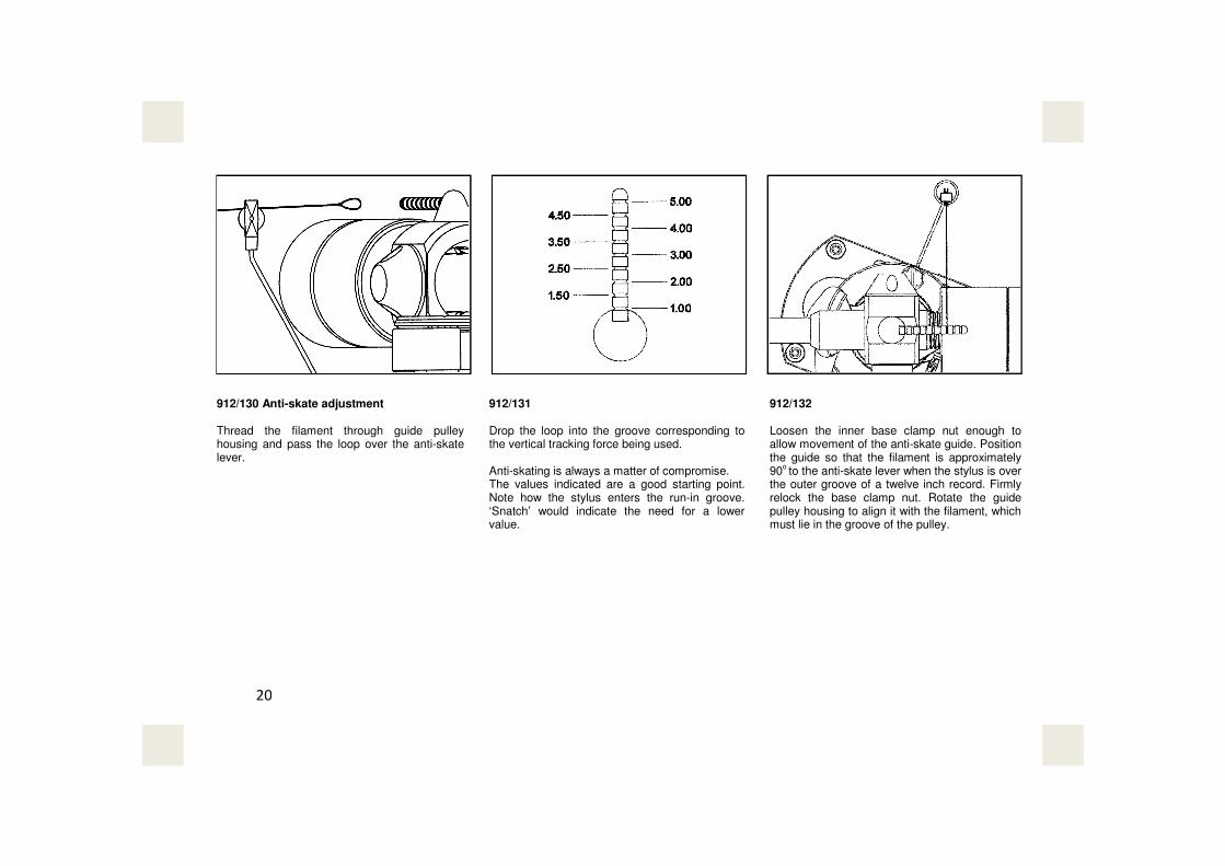
912/130 Anti-skate adjustment Thread the filament through guide pulley housing and pass the loop over the anti-skate lever.
912/131 Drop the loop into the groove corresponding to the vertical tracking force being used. Anti-skating is always a matter of compromise. The values indicated are a good starting point. Note how the stylus enters the run-in groove. ‘Snatch’ would indicate the need for a lower value.
912/132 Loosen the inner base clamp nut enough to allow movement of the anti-skate guide. Position the guide so that the filament is approximately 90
o to the anti-skate lever when the stylus is over
the outer groove of a twelve inch record. Firmly relock the base clamp nut. Rotate the guide pulley housing to align it with the filament, which must lie in the groove of the pulley.
20

912/133 Operation Rotate the control lever fully, in the direction of the arrow, and move the tonearm out from the armrest.
912/134 Position the arm so that the stylus is over the selected track of the record.
912/135 To lower the stylus onto the record move the control lever forwards, in direction of the arrow, just past top dead centre. This will set the control lever in motion, at which point it will take over the movement of the lever, giving a smooth controlled descent. Note: For the correct descent times the control lever must be operated exactly as above. The descent speed will be increased considerably if the lever is pushed down instead of being allowed to fall of its own accord.
21

912/136 Operation (continued) To raise the stylus from the record move the control lever back to its original position. When the arm is not in use it should always be returned to the armrest for safety.
912/137 Adjusting the height of lift The raising and lowering control is set to suit the majority of cartridges but the height raised above the record can be changed to meet individual needs. The small hole in the centre of the arm lift provides access to the adjustment screw. Insert the long leg of the 0.89mm A/F wrench to engage the screw. Clockwise rotation will decrease the height lifted; anti-clockwise rotation will increase it. The adjustment is sensitive so the wrench should only be turned a few degrees at a time. Apply firm downward pressure to the arm lift after each clockwise rotation of the adjustment screw.
912/138 Cleaning the arm lift If the arm drifts outwards during raising or lowering it indicates contaminant on the rubber pad. To restore positive working, wipe the pad with a damp cloth and repeat with a paper tissue until dry. Clean the underside of the tone arm in the same manner where it contacts the rubber pad.
22

23
Appendix
We hope these instructions have made the installation of your Series M2-9R/12R precision pick-up arm straightforward. Care for it as you would a camera. Do not apply oil or any other lubricant to any part of it. Do not attempt to take to pieces or interfere with any of the screws except as directed in the instructions; to do so will invalidate the warranty and may occasion costly repairs. If you have a problem concerning operation or service, contact us at the address overleaf in the first instance, quoting the unit’s model and serial number. Do notsend the arm to us unless requested to do so. We provide a quick, efficient service through our agents or direct from the factory to any part of the world.

Manufactured by:
SME LTD · STEYNING · SUSSEX · BN44 3GY · ENGLAND tel: +44 (0)1903 814321 · email: [email protected] · www.sme.ltd.uk