series mg369xb synthesized signal generators operation manual · sion components, do not remove the...
TRANSCRIPT

490 JARVIS DRIVEMORGAN HILL, CA 95037-2809
SERIES
MG369XB
SYNTHESIZED SIGNAL GENERATORS
OPERATION MANUAL
P/N: 10370-10365REVISION: D
PRINTED: MARCH 2007COPYRIGHT 2007 ANRITSU CO.

WARRANTYThe Anritsu product(s) listed on the title page is (are) warranted against defects in materials andworkmanship for three years from the date of shipment.
Anritsu's obligation covers repairing or replacing products which prove to be defective during thewarranty period. Buyers shall prepay transportation charges for equipment returned to Anritsu forwarranty repairs. Obligation is limited to the original purchaser. Anritsu is not liable for consequen-tial damages.
LIMITATION OF WARRANTYThe foregoing warranty does not apply to Anritsu connectors that have failed due to normal wear.Also, the warranty does not apply to defects resulting from improper or inadequate maintenance bythe Buyer, unauthorized modification or misuse, or operation outside of the environmental specifica-tions of the product. No other warranty is expressed or implied, and the remedies provided hereinare the Buyer's sole and exclusive remedies.
TRADEMARK ACKNOWLEDGMENTSAdobe Acrobat is a registered trademark of Adobe Systems Incorporated.
NOTICEAnritsu Company has prepared this manual for use by Anritsu Company personnel and customersas a guide for the proper installation, operation, and maintenance of Anritsu Company equipmentand computer programs. The drawings, specifications, and information contained herein are theproperty of Anritsu Company, and any unauthorized use or disclosure of these drawings, specifica-tions, and information is prohibited; they shall not be reproduced, copied, or used in whole or in partas the basis for manufacture or sale of the equipment or software programs without the prior writ-ten consent of Anritsu Company.
UPDATESUpdates to this manual, if any, may be downloaded from the Anritsu Internet site at:http://www.us.anritsu.com

Safety Symbols
To prevent the risk of personal injury or loss related to equipment malfunction, Anritsu Company uses thefollowing symbols to indicate safety-related information. For your own safety, please read the informationcarefully BEFORE operating the equipment.
WARNING WARNING indicates a hazard. It calls attention to a procedure thatcould result in personal injury or loss of life if not performed properly.Do not proceed beyond a WARNING notice until the indicated condi-tions are fully understood and met.
CAUTION CAUTION indicates a hazard. It calls attention to a procedure which,if not performed properly, could result in damage to or destruction of acomponent of the instrument. Do not proceed beyond a CAUTION noteuntil the indicated conditions are fully understood and met.
The instrument is marked with this symbol to indicate that it is neces-sary for the user to refer to the instructions in the operation manual.
Indicates ground.
MG369XB OM Safety-1

Safety-2 MG369XB OM
There are no operator serviceable components inside. Referservicing of the instrument to qualified service technicians.
To prevent the risk of electrical shock or damage to preci-sion components, do not remove the equipment covers.
WARNING
When supplying power to this equipment, always use athree-wire power cable connected to a three-wire power lineoutlet. If power is supplied without grounding the equip-ment in this manner, there is a risk of receiving a severe orfatal electric shock.
WARNING
For Safety
If the equipment is used in a manner not specified by themanufacturer, the protection provided by the equipmentmay be impaired.
WARNING
Before changing the fuse, always remove the power cordfrom the power outlet. There is the risk of receiving a fatalelectric shock if the fuse is replaced with the power cordconnected.
Always use a new fuse of the type and rating specified bythe fuse markings on the rear panel of the instrument.
WARNING
Table of Contents
Chapter 1 General Information1-1 Scope of Manual . . . . . . . . . . . . . . . . . . . . . . . . . . . . 1-3
1-2 Introduction . . . . . . . . . . . . . . . . . . . . . . . . . . . . . . 1-3
1-3 Description . . . . . . . . . . . . . . . . . . . . . . . . . . . . . . . 1-3
1-4 Identification Number . . . . . . . . . . . . . . . . . . . . . . . . . 1-3
1-5 Electronic Manual . . . . . . . . . . . . . . . . . . . . . . . . . . . 1-4
1-6 Related Manuals . . . . . . . . . . . . . . . . . . . . . . . . . . . . 1-4GPIB Programming Manual . . . . . . . . . . . . . . . . . 1-4Maintenance Manual . . . . . . . . . . . . . . . . . . . . . 1-4
1-7 Options . . . . . . . . . . . . . . . . . . . . . . . . . . . . . . . . . 1-4
1-8 Performance Specifications . . . . . . . . . . . . . . . . . . . . . . 1-7
1-9 Recommended Test Equipment . . . . . . . . . . . . . . . . . . . . 1-7
Chapter 2 Installation2-1 Introduction . . . . . . . . . . . . . . . . . . . . . . . . . . . . . . 2-3
2-2 Initial Inspection . . . . . . . . . . . . . . . . . . . . . . . . . . . . 2-3
2-3 Preparation For Use . . . . . . . . . . . . . . . . . . . . . . . . . . 2-3
2-4 Rack Mounting Kit Installation . . . . . . . . . . . . . . . . . . . . 2-5Preliminary . . . . . . . . . . . . . . . . . . . . . . . . . 2-5Procedure . . . . . . . . . . . . . . . . . . . . . . . . . . 2-5Power Requirements . . . . . . . . . . . . . . . . . . . . . 2-8Power Connection . . . . . . . . . . . . . . . . . . . . . . 2-8Standby Operation . . . . . . . . . . . . . . . . . . . . . . 2-9Warmup Time . . . . . . . . . . . . . . . . . . . . . . . . 2-9Operating Environment . . . . . . . . . . . . . . . . . . . 2-9
2-5 GPIB Setup and Interconnection. . . . . . . . . . . . . . . . . . . 2-10Interface Connector . . . . . . . . . . . . . . . . . . . . . 2-10Cable Length Restrictions . . . . . . . . . . . . . . . . . . 2-10GPIB Interconnection . . . . . . . . . . . . . . . . . . . . 2-10Setting the GPIB Address . . . . . . . . . . . . . . . . . . 2-11Selecting the Line Terminator . . . . . . . . . . . . . . . . 2-12Interface Language . . . . . . . . . . . . . . . . . . . . . 2-12
MG369XB OM i

2-6 Preparation for Storage/Shipment . . . . . . . . . . . . . . . . . . 2-13Preparation for Storage . . . . . . . . . . . . . . . . . . . 2-13Preparation for Shipment . . . . . . . . . . . . . . . . . . 2-13
2-7 Anritsu Service Centers . . . . . . . . . . . . . . . . . . . . . . . 2-14
Chapter 3 Local (Front Panel) Operation3-1 Introduction . . . . . . . . . . . . . . . . . . . . . . . . . . . . . . 3-5
Typographic Conventions . . . . . . . . . . . . . . . . . . . 3-5
3-2 Front Panel Layout. . . . . . . . . . . . . . . . . . . . . . . . . . . 3-6Line Key . . . . . . . . . . . . . . . . . . . . . . . . . . . 3-6Data Display Area . . . . . . . . . . . . . . . . . . . . . . 3-6Data Entry Area . . . . . . . . . . . . . . . . . . . . . . . 3-7RF Output Control Key. . . . . . . . . . . . . . . . . . . . 3-7RF Output Connector. . . . . . . . . . . . . . . . . . . . . 3-7
3-3 Data Display Area . . . . . . . . . . . . . . . . . . . . . . . . . . . 3-8Menu Display Format . . . . . . . . . . . . . . . . . . . . 3-9Menu Keys . . . . . . . . . . . . . . . . . . . . . . . . . 3-10
3-4 Data Entry Area . . . . . . . . . . . . . . . . . . . . . . . . . . . 3-12
3-5 Instrument Start-Up . . . . . . . . . . . . . . . . . . . . . . . . . 3-14Powering Up the MG369XB . . . . . . . . . . . . . . . . . 3-14Start-Up Display . . . . . . . . . . . . . . . . . . . . . . 3-14Standby Operation . . . . . . . . . . . . . . . . . . . . . 3-14Self-Testing the MG369XB . . . . . . . . . . . . . . . . . 3-15Resetting to Default Parameters . . . . . . . . . . . . . . . 3-15
3-6 Entering Data . . . . . . . . . . . . . . . . . . . . . . . . . . . . . 3-17Opening the Parameter . . . . . . . . . . . . . . . . . . . 3-17Editing the Current Value . . . . . . . . . . . . . . . . . . 3-18Entering a New Value . . . . . . . . . . . . . . . . . . . . 3-19
3-7 CW Frequency Operation. . . . . . . . . . . . . . . . . . . . . . . 3-20Selecting CW Mode . . . . . . . . . . . . . . . . . . . . . 3-20Selecting a CW Frequency . . . . . . . . . . . . . . . . . . 3-20Selecting a Power Level . . . . . . . . . . . . . . . . . . . 3-22CW Ramp . . . . . . . . . . . . . . . . . . . . . . . . . . 3-23Phase Offset . . . . . . . . . . . . . . . . . . . . . . . . 3-24Electronic Frequency Control . . . . . . . . . . . . . . . . 3-25
ii MG369XB OM
Table of Contents (Continued)

3-8 Sweep Frequency Operation . . . . . . . . . . . . . . . . . . . . . 3-26Analog Sweep Mode . . . . . . . . . . . . . . . . . . . . . 3-26Selecting Analog Sweep Mode . . . . . . . . . . . . . . . . 3-26Setting Sweep Time . . . . . . . . . . . . . . . . . . . . . 3-27Step Sweep Mode . . . . . . . . . . . . . . . . . . . . . . 3-28Selecting Step Sweep Mode . . . . . . . . . . . . . . . . . 3-28Setting Step Size, Dwell Time, and Sweep Time . . . . . . . 3-29Selecting a Sweep Trigger . . . . . . . . . . . . . . . . . . 3-31Manual Sweep Mode . . . . . . . . . . . . . . . . . . . . 3-32Selecting Manual Sweep Mode. . . . . . . . . . . . . . . . 3-33Selecting a Sweep Range . . . . . . . . . . . . . . . . . . 3-33Selecting a Power Level . . . . . . . . . . . . . . . . . . . 3-36Frequency Markers . . . . . . . . . . . . . . . . . . . . . 3-36Selecting Alternate Sweep Mode . . . . . . . . . . . . . . . 3-38List Sweep Mode . . . . . . . . . . . . . . . . . . . . . . 3-42Selecting List Sweep Mode . . . . . . . . . . . . . . . . . 3-43List Frequency Editing . . . . . . . . . . . . . . . . . . . 3-45List Power Editing . . . . . . . . . . . . . . . . . . . . . 3-46Selecting a List Sweep Range . . . . . . . . . . . . . . . . 3-48Selecting a List Sweep Trigger . . . . . . . . . . . . . . . 3-49
3-9 Fixed Power Level Operation. . . . . . . . . . . . . . . . . . . . . 3-51Selecting Fixed Power Level Mode . . . . . . . . . . . . . . 3-51Selecting a Power Level . . . . . . . . . . . . . . . . . . . 3-51Level Offset . . . . . . . . . . . . . . . . . . . . . . . . . 3-54
3-10 Power Level Sweep Operation . . . . . . . . . . . . . . . . . . . . 3-56Selecting CW Power Sweep Mode . . . . . . . . . . . . . . 3-56Setting CW Power Sweep Step Size and Dwell Time . . . . . 3-57Selecting a CW Power Sweep Trigger . . . . . . . . . . . . 3-57Selecting a Power Level Sweep Range . . . . . . . . . . . . 3-59Selecting a Sweep Frequency/Step Power Mode . . . . . . . 3-61Setting Power Level Step Size . . . . . . . . . . . . . . . . 3-62
3-11 Leveling Operations . . . . . . . . . . . . . . . . . . . . . . . . . 3-63Selecting a Leveling Mode . . . . . . . . . . . . . . . . . . 3-63Attenuator Decoupling . . . . . . . . . . . . . . . . . . . 3-67ALC Power Slope . . . . . . . . . . . . . . . . . . . . . . 3-68User Cal (User Power Level Flatness Calibration) . . . . . . 3-70
MG369XB OM iii
Table of Contents (Continued)

3-12 System Configuration. . . . . . . . . . . . . . . . . . . . . . . . . 3-76Accessing the System Configuration Menu . . . . . . . . . . 3-76Configuring the Front Panel . . . . . . . . . . . . . . . . 3-77Configuring the Rear Panel . . . . . . . . . . . . . . . . . 3-78Configuring the RF . . . . . . . . . . . . . . . . . . . . . 3-79Configuring the GPIB . . . . . . . . . . . . . . . . . . . . 3-81Setting Increment Sizes . . . . . . . . . . . . . . . . . . . 3-84
3-13 Saving/Recalling Instrument Setups. . . . . . . . . . . . . . . . . 3-85Saving Setups . . . . . . . . . . . . . . . . . . . . . . . . 3-85Recalling Setups . . . . . . . . . . . . . . . . . . . . . . 3-86Erasing Stored Setups. . . . . . . . . . . . . . . . . . . . 3-86
3-14 Secure Operation . . . . . . . . . . . . . . . . . . . . . . . . . . . 3-87Memory Profile and Security Issues . . . . . . . . . . . . . 3-87
3-15 Reference Loop Adjustments . . . . . . . . . . . . . . . . . . . . . 3-88Reference Oscillator Calibration . . . . . . . . . . . . . . . 3-88Reference Loop Bandwidth . . . . . . . . . . . . . . . . . 3-90
3-16 Signal Modulation . . . . . . . . . . . . . . . . . . . . . . . . . . 3-92Accessing Modulation Modes . . . . . . . . . . . . . . . . 3-92Amplitude Modulation Operating Modes . . . . . . . . . . . 3-93Providing Amplitude Modulation . . . . . . . . . . . . . . 3-93Frequency Modulation Operating Modes . . . . . . . . . . . 3-96Providing Frequency Modulation . . . . . . . . . . . . . . 3-97Phase Modulation Operating Modes . . . . . . . . . . . . 3-101Providing Phase Modulation . . . . . . . . . . . . . . . . 3-102Pulse Modulation Operating Modes. . . . . . . . . . . . . 3-106Providing Pulse Modulation . . . . . . . . . . . . . . . . 3-107
3-17 Internal Power Meter (Option 8) . . . . . . . . . . . . . . . . . . 3-116
3-18 Scan Modulation (Option 20) . . . . . . . . . . . . . . . . . . . . 3-119
Chapter 4 Local Operation—Menu Maps4-1 Introduction . . . . . . . . . . . . . . . . . . . . . . . . . . . . . . 4-3
4-2 Menu Map Description. . . . . . . . . . . . . . . . . . . . . . . . . 4-3
iv MG369XB OM
Table of Contents (Continued)

Chapter 5 Operation Verification5-1 Introduction . . . . . . . . . . . . . . . . . . . . . . . . . . . . . . 5-3
5-2 Test Equipment . . . . . . . . . . . . . . . . . . . . . . . . . . . . 5-3
5-3 Test Records . . . . . . . . . . . . . . . . . . . . . . . . . . . . . . 5-4
5-4 Initial MG369XB Checkout . . . . . . . . . . . . . . . . . . . . . . 5-4Power Up . . . . . . . . . . . . . . . . . . . . . . . . . . 5-4Self-Test . . . . . . . . . . . . . . . . . . . . . . . . . . . 5-4Resetting the MG369XB . . . . . . . . . . . . . . . . . . . 5-4Warmup Time . . . . . . . . . . . . . . . . . . . . . . . . 5-4
5-5 Frequency Synthesis Test . . . . . . . . . . . . . . . . . . . . . . . 5-5Test Setup . . . . . . . . . . . . . . . . . . . . . . . . . . 5-5Test Procedure . . . . . . . . . . . . . . . . . . . . . . . . 5-5
5-6 Level Accuracy and Flatness Tests. . . . . . . . . . . . . . . . . . 5-10Test Setup . . . . . . . . . . . . . . . . . . . . . . . . . 5-10Power Level Accuracy Test Procedure . . . . . . . . . . . . 5-11Power Level Flatness Test Procedure . . . . . . . . . . . . 5-12
Chapter 6 Operator Maintenance6-1 Introduction . . . . . . . . . . . . . . . . . . . . . . . . . . . . . . 6-3
6-2 Error and Warning/Status Messages . . . . . . . . . . . . . . . . . 6-3Self-Test Error Messages . . . . . . . . . . . . . . . . . . . 6-3Normal Operation Error and Warning/Status Messages . . . . 6-8
6-3 Troubleshooting . . . . . . . . . . . . . . . . . . . . . . . . . . . . 6-11
6-4 Routine Maintenance . . . . . . . . . . . . . . . . . . . . . . . . . 6-14Cleaning the Fan Filters. . . . . . . . . . . . . . . . . . . 6-14Cleaning the Data Display. . . . . . . . . . . . . . . . . . 6-14Replacing the Line Fuses . . . . . . . . . . . . . . . . . . 6-14
MG369XB OM v
Table of Contents (Continued)

Chapter 7 Use With Other Instruments7-1 Introduction . . . . . . . . . . . . . . . . . . . . . . . . . . . . . . 7-3
7-2 Master-Slave Operation . . . . . . . . . . . . . . . . . . . . . . . . 7-4Connecting the Instruments . . . . . . . . . . . . . . . . . 7-4Initiating Master-Slave Operation . . . . . . . . . . . . . . 7-5Master-Slave Operation. . . . . . . . . . . . . . . . . . . . 7-7Master-Slave Operation in VNA Mode . . . . . . . . . . . . 7-7Terminating Master-Slave Operation . . . . . . . . . . . . . 7-9
7-3 Use with a 56100A Scalar Network Analyzer . . . . . . . . . . . . 7-10Connecting the MG369XB to the 56100A . . . . . . . . . . 7-10
7-4 Use with a 8003 Scalar Network Analyzer . . . . . . . . . . . . . 7-11Connecting the MG369XB to the 8003 . . . . . . . . . . . . 7-11Setting Up the MG369XB . . . . . . . . . . . . . . . . . . 7-12Initiating 8003 SNA Operation . . . . . . . . . . . . . . . 7-13
7-5 Use with a HP8757D Scalar Network Analyzer. . . . . . . . . . . 7-15Connecting the MG369XB to a HP8757D . . . . . . . . . . 7-15Setting Up the MG369XB . . . . . . . . . . . . . . . . . . 7-16Initiating HP8757D SNA Operation . . . . . . . . . . . . . 7-18
7-6 IF Up-Conversion (Option 7) . . . . . . . . . . . . . . . . . . . . . 7-19MG369XB Mixer Setup . . . . . . . . . . . . . . . . . . . 7-20
7-7 mmWave Source Modules . . . . . . . . . . . . . . . . . . . . . . 7-21
Appendix A Rear Panel ConnectorsA-1 Introduction . . . . . . . . . . . . . . . . . . . . . . . . . . . . . . A-1
A-2 Rear Panel Connectors . . . . . . . . . . . . . . . . . . . . . . . . A-1
A-3 Connector Pin-out Diagrams . . . . . . . . . . . . . . . . . . . . . A-1
Appendix B Performance Specifications
Subject Index
vi MG369XB OM
Table of Contents (Continued)

Table of Contents
1-1 Scope of Manual . . . . . . . . . . . . . . . . . . . . . . . . . . . . 1-3
1-2 Introduction . . . . . . . . . . . . . . . . . . . . . . . . . . . . . . 1-3
1-3 Description . . . . . . . . . . . . . . . . . . . . . . . . . . . . . . . 1-3
1-4 Identification Number . . . . . . . . . . . . . . . . . . . . . . . . . 1-3
1-5 Electronic Manual . . . . . . . . . . . . . . . . . . . . . . . . . . . 1-4
1-6 Related Manuals . . . . . . . . . . . . . . . . . . . . . . . . . . . . 1-4GPIB Programming Manual . . . . . . . . . . . . . . . . . 1-4Maintenance Manual . . . . . . . . . . . . . . . . . . . . . 1-4
1-7 Options . . . . . . . . . . . . . . . . . . . . . . . . . . . . . . . . . 1-4
1-8 Performance Specifications . . . . . . . . . . . . . . . . . . . . . . 1-7
1-9 Recommended Test Equipment . . . . . . . . . . . . . . . . . . . . 1-7
Chapter 1General Information

1-2 MG369XB OM
Figure 1-1. Series MG369XB Synthesized Signal Generator

Chapter 1General Information
1-1 Scope of Manual This manual provides general information, installation, and operatinginformation for the Anritsu series MG369XB synthesized signal gener-ator. Throughout this manual, the terms MG369XB, signal generator,and synthesizer will be used interchangeably to refer to the instru-ment. Manual organization is shown in the table of contents.
1-2 Introduction This chapter contains general information about the series MG369XBsignal generators. It includes a general description of the instrumentand information on its identification number, related manuals, options,and performance specifications. A listing of recommended test equip-ment is also provided.
1-3 Description The series MG369XB synthesized signal generators are microproces-sor-based, synthesized signal sources with high resolution phase-lockcapability. They generate both discrete CW frequencies and broad (fullrange) and narrow band step sweeps across the frequency range of2 GHz to 67 GHz. Options are available to extend the low end of thefrequency range to 0.1 Hz. All functions of the signal generator arefully controllable locally from the front panel or remotely (except forpower on/standby) via the IEEE-488 General Purpose Interface Bus(GPIB). Table 1-1, page 1-5, lists models, frequency ranges, and maxi-mum leveled output.
1-4 IdentificationNumber
All Anritsu instruments are assigned a unique six-digit ID number,such as “020312”. The ID number is imprinted on a decal that is af-fixed to the rear panel of the unit. Special-order instrument configura-tions also have an additional specials number tag attached to the rearpanel of the unit, such as SM1234.
When ordering parts or corresponding with Anritsu Customer Service,please use the correct serial number with reference to the specific in-strument's model number (for example, model MG3693B synthesizedsignal generator, serial number: 020312).
MG369XB OM 1-3

1-5 Electronic Manual Updated manuals are available for download from the document areaof the Anritsu web site at: http://www.us.anritsu.com.
1-6 Related Manuals This is one of a three manual set that consists of an operation manual,a GPIB programming manual, and a maintenance manual.
GPIBProgrammingManual
The Series MG369XB Synthesized Signal GeneratorGPIB Programming Manual provides informationfor remote operation of the signal generator withproduct specific commands sent from an externalcontroller via the IEEE 488 General Purpose Inter-face Bus (GPIB). It contains a general description ofthe GPIB and bus data transfer and control func-tions, a complete listing and description of allMG369XB GPIB product specific commands, andseveral programming examples. The Anritsu partnumber for the GPIB programming manual is10370-10366.
MaintenanceManual
The Series MG369XB Synthesized Signal GeneratorMaintenance Manual supplies service informationfor all models in the MG369XB series. The serviceinformation includes functional circuit descriptions,block diagrams, performance verification tests, cali-bration procedures, troubleshooting data, and as-sembly and component removal/replacementprocedures. The Anritsu part number for the main-tenance manual is 10370-10367.
1-7 Options The series MG369XB synthesizer provides a wide array of instrumentconfigurations through a series of base model and option choices.Table 1-1, on page 1-5, lists the available models with frequencyranges. Refer to Appendix B, MG3690B RF/Microwave SignalGenerators Technical Datasheet, P/N: 11410-00344, for currentinformation.
1-4 MG369XB OM
Options General Information

General Information Options
MG369XB OM 1-5
ModelNumber
ConfigurationFrequency
Range
MG3691BWith Option 4 or 5
Standard�0.01 – �10.0 GHz�2.0 – �10.0 GHz
MG3692BWith Option 4 or 5
Standard�0.01 – �20.0 GHz�2.0 – �20.0 GHz
MG3693BWith Option 4 or 5
Standard�0.01 – �30.0 GHz�2.0 – �30.0 GHz
MG3694BWith Option 4 or 5
Standard�0.01 – �40.0 GHz�2.0 – �40.0 GHz
MG3695BWith Option 4 or 5
Standard�0.01 – �50.0 GHz�2.0 – �50.0 GHz
MG3696BWith Option 4 or 5
Standard�0.01 – �67.0 GHz*�2.0 – �67.0 GHz*
*Operational to 70.0 GHz
Options List
Option 1A:Rack Mounting with Slides—Rack mount kit containing a set of track slides (90� tilt capability), mountingears, and front panel handles for mounting the instrument in a standard 19-inch equipment rack.
Option 1B:Rack Mounting without Slides—Modifies rack mounting hardware to install unit in a console that hasmounting shelves. Includes mounting ears and front panel handles.
Option 2X:110 dB Mechanical Step Attenuator—Adds a 10 dB per step attenuator with a 110 dB range. Output poweris selected directly in dBm on the front panel (or via GPIB). Rated RF output power is reduced.
Option 2E:120 dB Electronic Step Attenuator—Adds a 10 dB per step attenuator with a 120 dB range for modelshaving a high-end frequency of �20 GHz. Output power is selected directly in dBm on the front panel (or viaGPIB). Rated RF output power is reduced.
Option 3:Ultra-Low Phase Noise—Adds new modules that significantly reduces single-sideband phase noise,�2 GHz.
Option 4:Digital Down Converter—Adds a digital down converter for ultra-low phase noise for 0.01 to 2.2 GHz RFcoverage.
Option 5: Analog Down Converter—Adds an analog down converter for 0.01 to 2.0 GHz RF coverage.
Option 6: Analog Sweep Capability—Adds analog sweep capability. (Limited to �500 MHz when used with Option 4.)
Option 7:IF Up-Conversion—Adds an internal 40 GHz mixer for up-converting an IF signal. Not available inMG3695B, MG3696B, or with Option 18.
Option 8: Power Monitor—Adds internal power measurement capability. (Not available with Option 9.)
Option 9X: Rear Panel RF Output—Moves the RF output connector to the rear panel.
Option 10:User-Defined Modulation Waveform Software—Adds a software package that provides the ability to seri-ally (or via GPIB) download user-defined waveforms into the memory of the internal waveform generator.Requires an external PC and an instrument with an internal low frequency generator (Option 23).
Table 1-1. Series MG369XB Model and Option List (1 of 2)

1-6 MG369XB OM
Options General Information
Option 12:External Frequency and Phase Modulation—Adds external FM/�M capabilities via a rear panel BNC con-nector. Requires an external modulating signal input or an internal low frequency generator (Option 23).
Option 13X*:External Pulse Modulation—Adds external pulse modulation capability via a rear panel BNC connector.Requires an external modulating signal input.
Option 14:Amplitude Modulation—Adds external AM capability via a rear panel BNC connector. Requires an externalmodulating signal input or an internal low frequency generator (Option 23).
Option 15X:High Power Output—Adds high-power RF components to the instrument providing increased RF outputpower.
Option 16:High-Stability Time Base—Adds an ovenized 10 MHz crystal oscillator with frequency stability of <5 x10⁻¹⁰/day.
Option 17:Delete Front Panel—Deletes the front panel for use in remote control applications where a front panel dis-play or keyboard control are not needed.
Option 18:mmW Bias Output—Adds a rear panel BNC Twinax connector to bias the 5400-xWRxx millimeter wavesource modules.
Option 20:Scan Modulation—Adds an internal Scan modulator for simulating high-depth amplitude modulated signals.Requires an external modulating signal input capability. (Not available on models MG3693B, MG3694B,MG3695B, MG3696B, or with Options 2E, 7, 15X, or 22.)
Option 22:0.1 Hz to 10.0 MHz Audio Frequency—Adds frequency coverage below 10 MHz. The frequency resolutionbelow 10 MHz is 0.02 Hz. Rated RF output power is reduced.
Option 23*:Low Frequency Generator—Provides modulation waveforms for internal AM, FM, or �M. Not availablewithout Option 12 or 14.
Option 24*:Internal Pulse Generator—Provides pulse waveforms for internal pulse modulation. Not available withoutOption 13.
Option 25X*:Analog Modulation Suite—The analog modulation suite bundles Options 12, 13, 14, 23 and 24, offering in-ternal and external AM, FM, �M, and pulse modulation.
Option 26X*:Pulse Modulation—Adds external pulse modulation via a rear panel BNC connector. For internalmodulation capability, requires additionally Pulse Generator, Option 27. (This option comes in differentversions based on instrument configuration.)
Option 27*:LF Generator—Provides modulation waveforms for internal AM, FM, FM, and Pulse. (Not available withoutOption 12, 14, or 26.)
Option 28X*:Analog Modulation Suite—For ease of ordering and package pricing, this option bundles Options 12, 14,26 and 27, offering internal and external AM, FM, FM, and Pulse Modulation. (This option comes in differentversions , based on instrument configuration.)
Option 30: Low Phase Noise
* May not be availlable for all instruments or may require additional upgrades. Contact Anritsu customer service for details.
Table 1-1. Series MG369XB Model and Option List (2 of 2)
1-8 PerformanceSpecifications
The series MG369XB synthesized signal generator performance speci-fications are provided in Appendix B.
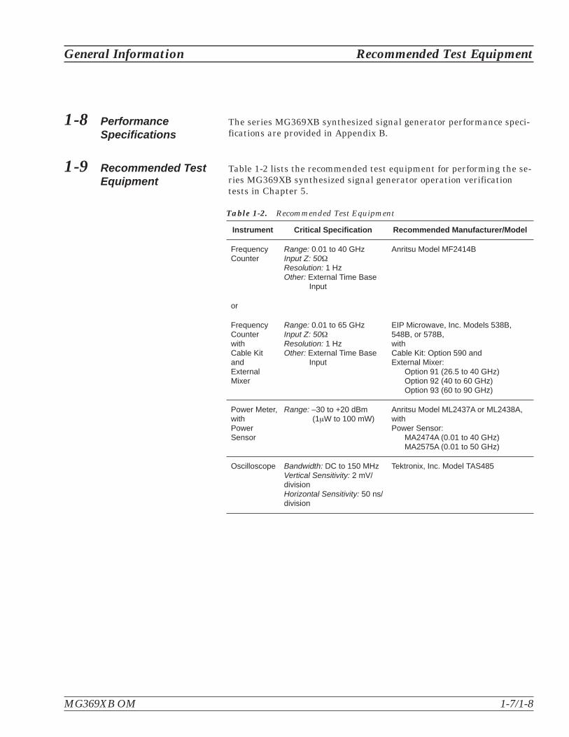
1-9 Recommended TestEquipment
Table 1-2 lists the recommended test equipment for performing the se-ries MG369XB synthesized signal generator operation verificationtests in Chapter 5.
General Information Recommended Test Equipment
MG369XB OM 1-7/1-8
Instrument Critical Specification Recommended Manufacturer/Model
FrequencyCounter
Range: 0.01 to 40 GHzInput Z: 50�
Resolution: 1 HzOther: External Time Base
Input
Anritsu Model MF2414B
or
FrequencyCounterwithCable KitandExternalMixer
Range: 0.01 to 65 GHzInput Z: 50�
Resolution: 1 HzOther: External Time Base
Input
EIP Microwave, Inc. Models 538B,548B, or 578B,withCable Kit: Option 590 andExternal Mixer:
Option 91 (26.5 to 40 GHz)Option 92 (40 to 60 GHz)Option 93 (60 to 90 GHz)
Power Meter,withPowerSensor
Range: –30 to +20 dBm(1�W to 100 mW)
Anritsu Model ML2437A or ML2438A,withPower Sensor:
MA2474A (0.01 to 40 GHz)MA2575A (0.01 to 50 GHz)
Oscilloscope Bandwidth: DC to 150 MHzVertical Sensitivity: 2 mV/divisionHorizontal Sensitivity: 50 ns/division
Tektronix, Inc. Model TAS485
Table 1-2. Recommended Test Equipment


Table of Contents
2-1 Introduction . . . . . . . . . . . . . . . . . . . . . . . . . . . . . . 2-3
2-2 Initial Inspection . . . . . . . . . . . . . . . . . . . . . . . . . . . . 2-3
2-3 Preparation For Use . . . . . . . . . . . . . . . . . . . . . . . . . . 2-3
2-4 Rack Mounting Kit Installation . . . . . . . . . . . . . . . . . . . . 2-5Preliminary . . . . . . . . . . . . . . . . . . . . . . . . . 2-5Procedure . . . . . . . . . . . . . . . . . . . . . . . . . . 2-5Power Requirements . . . . . . . . . . . . . . . . . . . . . 2-8Power Connection . . . . . . . . . . . . . . . . . . . . . . 2-8Standby Operation . . . . . . . . . . . . . . . . . . . . . . 2-9Warmup Time . . . . . . . . . . . . . . . . . . . . . . . . 2-9Operating Environment . . . . . . . . . . . . . . . . . . . 2-9
2-5 GPIB Setup and Interconnection. . . . . . . . . . . . . . . . . . . 2-10Interface Connector . . . . . . . . . . . . . . . . . . . . . 2-10Cable Length Restrictions . . . . . . . . . . . . . . . . . . 2-10GPIB Interconnection . . . . . . . . . . . . . . . . . . . . 2-10Setting the GPIB Address . . . . . . . . . . . . . . . . . . 2-11Selecting the Line Terminator . . . . . . . . . . . . . . . . 2-12Interface Language . . . . . . . . . . . . . . . . . . . . . 2-12
2-6 Preparation for Storage/Shipment . . . . . . . . . . . . . . . . . . 2-13Preparation for Storage . . . . . . . . . . . . . . . . . . . 2-13Preparation for Shipment . . . . . . . . . . . . . . . . . . 2-13
2-7 Anritsu Service Centers . . . . . . . . . . . . . . . . . . . . . . . 2-14
Chapter 2Installation


Chapter 2Installation
2-1 Introduction This chapter provides installation instructions for the seriesMG369XB synthesized signal generator. It includes information on ini-tial inspection, preparation for use, storage, reshipment, and GeneralPurpose Interface Bus (GPIB) setup and interconnections.
2-2 Initial Inspection Inspect the shipping container for damage. If the shipping container orcushioning material is damaged, retain until the contents of the ship-ment have been checked against the packing list and the signal gener-ator has been checked for mechanical and electrical operation.
If the shipment is incomplete or if the signal generator is damagedmechanically or electrically, notify your local sales representative orAnritsu Customer Service. If either the shipping container is damagedor the cushioning material shows signs of stress, notify the carrier aswell as Anritsu. Keep the shipping materials for the carrier's inspec-tion.
2-3 Preparation For Use Preparation for use consists of installing the instrument into asuitable operating location and connecting the signal generator to apower source. The following paragraphs provide these proceduresalong with information about power requirements, warmup times, andthe operating environment. Figure 2-1, on the following page,illustrates the basic outer dimensions of the instrument.
MG369XB OM 2-3

Preparation For Use Installation
2-4 MG369XB OM
Figure 2-1. MG369XB Outline Dimensions (in millimeters)

2-4 Rack Mounting KitInstallation
The rack mounting kit (Option 1A) contains a set of track slides (90�
tilt capability), mounting ears, and front panel handles for mountingthe signal generator in a standard equipment rack. The following pro-cedure provides instructions for installing the rack mounting hard-ware on to the instrument. The rack mounting kit (Option 1B) usesthe same inner assembly without the slide. This procedure may also beused for installing the Option 1B rack mount assembly. Refer to Fig-ures 2-3 and 2-4 during this procedure.
Preliminary Disconnect the power cord and any other cablesfrom the instrument.
Procedure Install the rack mounting hardware as follows:
Step 1. Using a Phillips screwdriver, remove thescrews and the front handle assembliesfrom the instrument. (For instrumentsnot having front handles, remove thescrews and the front top and bottom feetfrom the instrument.) Retain the screws.
Step 2. Remove the four feet from the rear of theinstrument. Retain the screws.
Installation Rack Mounting Kit Installation
MG369XB OM 2-5
Rear Feet(4)
Figure 2-3. Front Handle and Feet Removal

Step 3. Remove the inner slide assemblies fromthe outer slide assemblies.
Step 4. Place the left side inner slide assemblyonto the instrument case with the handletowards the front of the instrument (Fig-ure 2-4).
Step 5. Insert two green-headed screws throughthe holes in the slide assembly behind thehandle and into the metric tapped holesin the side of the instrument.
Step 6. Insert two green-headed screws throughthe holes near the rear of the slide assem-bly and into the metric tapped holes inthe side of the instrument.
Step 7. Insert the two SAE threaded screws (re-moved from the feet) through the 90� tabson the rear of the slide assembly and intothe rear panel of the instrument.
Step 8. Using the Phillips screwdriver, tighten allscrews holding the left side slide assem-bly to the instrument chassis.
Rack Mounting Kit Installation Installation
2-6 MG369XB OM
NOTEThe screws with green heads havemetric threads. When it becomesnecessary to replace any of thesescrews, always use the exact re-placement green-headed screws toavoid damage to the instrument.Anritsu P/N’s: 905-8 (long);Z-951102 (short).
Figure 2-4. Rack Mounting Hardware Installation

Step 9. Place the right side inner slide assemblyonto the instrument case with the handletowards the front of the instrument.
Step 10. Insert two green-headed screws throughthe holes in the slide assembly behind thehandle and into the metric tapped holesin the side of the instrument.
Step 11. Insert two green-headed screws throughthe holes near the rear of the slide assem-bly and into the metric tapped holes inthe side of the instrument.
Step 12. Insert the two SAE threaded screws (re-moved from the feet) through the 90� tabson the rear of the slide assembly and intothe rear panel of the instrument.
Step 13. Using the Phillips screwdriver, tighten allscrews holding the right side slide assem-bly to the instrument chassis.
Step 14. Using the appropriate hardware, installthe outer slide assemblies onto the equip-ment rack.
Step 15. Lift the signal generator into position.Align the inner and outer slide assem-blies and slide the instrument into therack. Realign the hardware as needed forsmooth operation.
Installation Rack Mounting Kit Installation
MG369XB OM 2-7

PowerRequirements
The signal generator accepts 90 to 264 Vac, 48 to440 Hz, single-phase power. Power consumption is300 VA maximum. The signal generator is intendedfor Installation Category (Over Voltage Category) II.
PowerConnection
To connect the MG369XB to the power source, plugthe female end of the power cable into the input linevoltage receptacle on the rear panel (Figure 2-2).Then plug the male end of the power cord into athree-wire power line outlet. Turn on the rear panelpower switch. This automatically places the signalgenerator in operation (front panel OPERATE LEDon).
Rack Mounting Kit Installation Installation
2-8 MG369XB OM
When supplying power to this equipment, always use athree-wire power cable connected to a three-wire power lineoutlet. If power is supplied without grounding the equip-ment in this manner, there is a risk of receiving a severe orfatal electric shock.
WARNING
Figure 2-2. Signal Generator Rear Panel Showing Power Connection

StandbyOperation
Whenever the signal generator is not being used itshould be left connected to the power source andplaced in standby. This keeps the internal time basefrequency reference at operating temperature.
On the front panel, press LINE to switch theMG369XB from OPERATE (green LED on) toSTANDBY (orange LED on). (Hold the LINE keydown for at least ½ second to prevent power-off ofthe unit.)
NOTEDuring standby operation, the fan runs con-tinuously.
Warmup Time From Standby–When placing the MG369XB in op-eration from standby, allow 30 minutes warmup toassure stable operation.
From a Cold Start (0�C)–The signal generator re-quires approximately 120 hours (5 days) of warm upto achieve specified frequency stability with aging.
NOTEInstruments disconnected from ac power formore than 72 hours require 30 days to return tospecified aging.
OperatingEnvironment
The MG369XB can be operated within the followingenvironmental limits.
� Temperature: 0�C to 50�C
� Humidity: 5 to 95% relative at 40�C
� Altitude: up to 4600 meters
� Cooling: Internal cooling is provided by forcedairflow from the fans mounted on the rearpanel
Installation Rack Mounting Kit Installation
MG369XB OM 2-9
Before installing the MG369XB in its operating environ-ment, ensure that all airflow passages at the sides and rearof the instrument are clear. This is of particular importancewhenever the unit is being rack-mounted.
Keep the cooling fan filters clean so that the ventilationholes are not obstructed. A blocked fan filter can cause theinstrument to overheat and shut down.
CAUTION
� � � � � � � � �
� � � �
� � � � � � � �

2-5 GPIB Setup andInterconnection
The MG369XB provides automated microwave signal generation viathe GPIB. The following paragraphs provide information about inter-face connections, cable requirements, setting the GPIB operating pa-rameters, and selecting the external interface language.
InterfaceConnector
Interface between the signal generator and other de-vices on the GPIB is via a 24-wire interface cable.This cable uses connector shells having two connec-tor faces. These double-faced connectors allow forthe parallel connection of two or more cables to asingle device.
Cable LengthRestrictions
The GPIB can accommodate up to 15 instruments atany one time. To achieve design performance on thebus, proper timing and voltage level relationshipsmust be maintained. If either the cable length be-tween separate instruments or the cumulative cablelength between all instruments is too long, the dataand control lines cannot be driven properly and thesystem may fail to perform. Cable length restric-tions are as follows:
� No more than 15 instruments may be installedon the bus
� Total cumulative cable length (in meters) maynot exceed two times the number of bus instru-ments or 20 meters—whichever is less
NOTEFor low EMI applications, the GPIB cableshould be a fully shielded type with well-grounded metal-shell connectors.
GPIBInterconnection
The only interconnection required for GPIB opera-tion is between the signal generator and the control-ler. This interconnection is via a standard GPIBcable. The Anritsu part number for such a cable is2100-1, -2, or -4 (1, 2, or 4 meters in length).
GPIB Setup and Interconnection Installation
2-10 MG369XB OM

Setting theGPIB Address
The default GPIB address is five. If a different GPIBaddress is desired, it can be set from the front panelusing the Configure GPIB menu.
To change the GPIB address, first press the frontpanel main menu key labeled System . The Systemmenu is displayed.
Now press the menu soft-key Config . The SystemConfiguration menu (shown below) is displayed.
To access the Configure GPIB menu from this menu,press the menu soft-key GPIB > . The ConfigureGPIB menu (shown below) is displayed.
Press the menu soft-key GPIB Address [ADD] tochange the current GPIB address of the signal gen-erator. Enter a new address using the cursor controlkeys or the data entry keypad and the terminatorsoft-key [ADR]. The new GPIB address will now ap-pear on the display. The entry must be between 1and 30 to be recognized as a valid GPIB address.
Installation GPIB Setup and Interconnection
MG369XB OM 2-11

Selecting theLineTerminator
Data is delimited on the GPIB by either the carriagereturn (CR) ASCII character or both the carriage re-turn and line feed (CR/LF) ASCII characters. Whichcharacter is used depends upon the requirements ofthe system controller. Most modern controllers canuse either CR or CR/LF, while many older control-lers require one or the other. Consult the controller'smanual for its particular requirements.
From the Configure GPIB menu display, you can se-lect which GPIB terminator to use by pressing themenu soft-key GPIB Terminator . This menu soft-keytoggles the GPIB terminator between CR andCR/LF. The current selection appears on the display.
InterfaceLanguage
The series MG369XB synthesized signal generatorscan be remotely operated via the GPIB using an ex-ternal interface language—Native. The Native in-terface language uses a set of MG369XB GPIBproduct specific commands to control the instru-ment. Detailed descriptions and a comprehensivelist of these commands can be found in theMG369XB programming manual, P/N: 10370-10366.
GPIB Setup and Interconnection Installation
2-12 MG369XB OM

2-6 Preparation forStorage/Shipment
The following paragraphs give instructions for preparing theMG369XB for storage or shipment.
Preparationfor Storage
Preparing the signal generator for storage consistsof cleaning the unit, packing the inside with mois-ture-absorbing desiccant crystals, and storing theunit in a temperature environment that is main-tained between –40�C and +75�C.
Preparationfor Shipment
To provide maximum protection against damage intransit, the signal generator should be repackagedin the original shipping container. If this containeris no longer available and the unit is being returnedto Anritsu for repair, advise Anritsu Customer Ser-vice; they will send a new shipping container free ofcharge. In the event neither of these two options ispossible, instructions for packaging and shipmentare given below.
Use a Suitable ContainerObtain a corrugated cardboard carton with a 125 kgtest strength. This carton should have inside dimen-sions of no less than 15 cm larger than the unit di-mensions to allow for cushioning (refer toFigure 2-1, page 2-4).
Protect the InstrumentSurround the unit with polyethylene sheeting toprotect the finish.
Cushion the InstrumentCushion the instrument on all sides by tightly pack-ing dunnage or urethane foam between the cartonand the unit. Provide at least three inches of dun-nage on all sides.
Seal the ContainerSeal the carton by using either shipping tape or anindustrial stapler.
Address the ContainerIf the instrument is being returned to Anritsu forservice, mark the address of the appropriate Anritsuservice center (Table 2-1, following page) and yourreturn address on the carton in one or more promi-nent locations.
Installation Preparation for Storage/Shipment
MG369XB OM 2-13

2-7 Anritsu ServiceCenters
Table 2-1, below, lists the contact information for Anritsu service cen-ters around the world.
Anritsu Service Centers Installation
2-14 MG369XB OM
UNITED STATES
ANRITSU COMPANY490 Jarvis DriveMorgan Hill, CA 95037-2809Telephone: 1-800-ANRITSUFAX: 408-776-1744
FRANCE
ANRITSU S.A9 Avenue du QuebecZone de Courtaboeuf91951 Les Ulis CedexTelephone: 016-09-21-550FAX: 016-44-61-065
JAPAN
ANRITSU CUSTOMER SERVICESLTD.5-1-1 Onna Atsugi-shiKanagawa-Prf. 243 JapanTelephone: 0462-96-6688FAX: 0462-25-8379
ANRITSU COMPANY10 New Maple Ave., Unit 305Pine Brook, NJ 07058Telephone: 1-800-ANRITSUFAX: 973-575-0092
GERMANY
ANRITSU GmbHKonrad-Zuse-Platz 181829 Muenchen, GermanyTelephone: +49 89 4423080FAX: +49 89 44230855
SINGAPORE
ANRITSU (SINGAPORE) PTE LTD.10, Hoe Chiang Road#07-01/02 Keppel TowersSingapore 089315Telephone: 6-282-2400FAX: 6-282-2533
ANRITSU COMPANY1155 E. Collins BlvdRichardson, TX 75081Telephone: 1-800-ANRITSUFAX: 972-671-1877
INDIA
MEERA AGENCIES PVT. LTD.23 Community CentreZamroodpur, Kailash Colony Extension,New Delhi, India 110 048Phone: 011-2-6442700/6442800FAX : 011-2-644250023
SOUTH AFRICA
ETECSA12 Surrey Square Office Park330 Surrey AvenueFerndale, Randburg, 2194South AfricaTelephone: 27-11-787-7200FAX: 27-11-787-0446
AUSTRALIA
ANRITSU PTY. LTD.Unit 21/270 Ferntree Gully RoadNotting Hill, Victoria 3168AustraliaTelephone: 03-9558-8177FAX: 03-9558-8255
ISRAEL
TECH-CENT, LTD.4 Raul Valenberg StTel-Aviv 69719Telephone: (03) 64-78-563FAX: (03) 64-78-334
SWEDEN
ANRITSU ABBorgafjordsgatan 13164 40 KISTA, SwedenTelephone: +46-8-53470700FAX: +46-8-53470730
BRAZIL
Anritsu Eletrônica Ltda.Praça Amadeu Amaral 27, 1º andarBela Vista, São Paulo, SP, BrasilCEP: 01327-010Telephone: 55-11-3283-2511Fax: 55-11-3288-6940
ITALY
ANRITSU Sp.ARoma OfficeVia E. Vittorini, 12900144 Roma EURTelephone: (06) 50-99-711FAX: (06) 50-22-425
TAIWAN
ANRITSU CO., INC.7F, No. 316, Section 1NeiHu RoadTaipei, Taiwan, R.O.C.Telephone: 886-2-8751-1816FAX: 886-2-8751-2126
CANADA
ANRITSU INSTRUMENTS LTD.700 Silver Seven Road, Suite 120Kanata, Ontario K2V 1C3Telephone: (613) 591-2003FAX: (613) 591-1006
KOREA
ANRITSU CORPORATION LTD.
8F Hyunjuk Building, 832-41Yeoksam Dong, Kangnam-KuSeoul, South Korea 135-080Telephone: 02-553-6603FAX: 02-553-6605
UNITED KINGDOM
ANRITSU LTD.200 Capability GreenLuton, BedfordshireLU1 3LU, EnglandTelephone: 015-82-433200FAX: 015-82-731303
CHINA
ANRITSU ELECTRONICS (SHANGHAI) CO.LTD.2F, Rm B, 52 Section Factory BuildingNo. 516 Fu Te Rd (N)Shanghai 200131 P.R. ChinaTelephone: 21-5868-0226FAX: 21-5868-0588
Table 2-1. Anritsu Service Centers
Table of Contents
3-1 Introduction . . . . . . . . . . . . . . . . . . . . . . . . . . . . . . 3-5Typographic Conventions . . . . . . . . . . . . . . . . . . . 3-5
3-2 Front Panel Layout. . . . . . . . . . . . . . . . . . . . . . . . . . . 3-6Line Key . . . . . . . . . . . . . . . . . . . . . . . . . . . 3-6Data Display Area . . . . . . . . . . . . . . . . . . . . . . 3-6Data Entry Area . . . . . . . . . . . . . . . . . . . . . . . 3-7RF Output Control Key. . . . . . . . . . . . . . . . . . . . 3-7RF Output Connector. . . . . . . . . . . . . . . . . . . . . 3-7
3-3 Data Display Area . . . . . . . . . . . . . . . . . . . . . . . . . . . 3-8Menu Display Format . . . . . . . . . . . . . . . . . . . . 3-9Menu Keys . . . . . . . . . . . . . . . . . . . . . . . . . 3-10
3-4 Data Entry Area . . . . . . . . . . . . . . . . . . . . . . . . . . . 3-12
3-5 Instrument Start-Up . . . . . . . . . . . . . . . . . . . . . . . . . 3-14Powering Up the MG369XB . . . . . . . . . . . . . . . . . 3-14Start-Up Display . . . . . . . . . . . . . . . . . . . . . . 3-14Standby Operation . . . . . . . . . . . . . . . . . . . . . 3-14Self-Testing the MG369XB . . . . . . . . . . . . . . . . . 3-15Resetting to Default Parameters . . . . . . . . . . . . . . . 3-15
3-6 Entering Data . . . . . . . . . . . . . . . . . . . . . . . . . . . . . 3-17Opening the Parameter . . . . . . . . . . . . . . . . . . . 3-17Editing the Current Value . . . . . . . . . . . . . . . . . . 3-18Entering a New Value . . . . . . . . . . . . . . . . . . . . 3-19
Chapter 3Local (Front Panel) Operation
3-7 CW Frequency Operation. . . . . . . . . . . . . . . . . . . . . . . 3-20Selecting CW Mode . . . . . . . . . . . . . . . . . . . . . 3-20Selecting a CW Frequency . . . . . . . . . . . . . . . . . . 3-20Selecting a Power Level . . . . . . . . . . . . . . . . . . . 3-22CW Ramp . . . . . . . . . . . . . . . . . . . . . . . . . . 3-23Phase Offset . . . . . . . . . . . . . . . . . . . . . . . . 3-24Electronic Frequency Control . . . . . . . . . . . . . . . . 3-25
3-8 Sweep Frequency Operation . . . . . . . . . . . . . . . . . . . . . 3-26Analog Sweep Mode . . . . . . . . . . . . . . . . . . . . . 3-26Selecting Analog Sweep Mode . . . . . . . . . . . . . . . . 3-26Setting Sweep Time . . . . . . . . . . . . . . . . . . . . . 3-27Step Sweep Mode . . . . . . . . . . . . . . . . . . . . . . 3-28Selecting Step Sweep Mode . . . . . . . . . . . . . . . . . 3-28Setting Step Size, Dwell Time, and Sweep Time . . . . . . . 3-29Selecting a Sweep Trigger . . . . . . . . . . . . . . . . . . 3-31Manual Sweep Mode . . . . . . . . . . . . . . . . . . . . 3-32Selecting Manual Sweep Mode. . . . . . . . . . . . . . . . 3-33Selecting a Sweep Range . . . . . . . . . . . . . . . . . . 3-33Selecting a Power Level . . . . . . . . . . . . . . . . . . . 3-36Frequency Markers . . . . . . . . . . . . . . . . . . . . . 3-36Selecting Alternate Sweep Mode . . . . . . . . . . . . . . . 3-38List Sweep Mode . . . . . . . . . . . . . . . . . . . . . . 3-42Selecting List Sweep Mode . . . . . . . . . . . . . . . . . 3-43List Frequency Editing . . . . . . . . . . . . . . . . . . . 3-45List Power Editing . . . . . . . . . . . . . . . . . . . . . 3-46Selecting a List Sweep Range . . . . . . . . . . . . . . . . 3-48Selecting a List Sweep Trigger . . . . . . . . . . . . . . . 3-49
3-9 Fixed Power Level Operation. . . . . . . . . . . . . . . . . . . . . 3-51Selecting Fixed Power Level Mode . . . . . . . . . . . . . . 3-51Selecting a Power Level . . . . . . . . . . . . . . . . . . . 3-51Level Offset . . . . . . . . . . . . . . . . . . . . . . . . . 3-54
3-10 Power Level Sweep Operation . . . . . . . . . . . . . . . . . . . . 3-56Selecting CW Power Sweep Mode . . . . . . . . . . . . . . 3-56Setting CW Power Sweep Step Size and Dwell Time . . . . . 3-57Selecting a CW Power Sweep Trigger . . . . . . . . . . . . 3-57Selecting a Power Level Sweep Range . . . . . . . . . . . . 3-59Selecting a Sweep Frequency/Step Power Mode . . . . . . . 3-61Setting Power Level Step Size . . . . . . . . . . . . . . . . 3-62
3-2 MG369XB OM
Table of Contents (Continued)

3-11 Leveling Operations . . . . . . . . . . . . . . . . . . . . . . . . . 3-63Selecting a Leveling Mode . . . . . . . . . . . . . . . . . . 3-63Attenuator Decoupling . . . . . . . . . . . . . . . . . . . 3-67ALC Power Slope . . . . . . . . . . . . . . . . . . . . . . 3-68User Cal (User Power Level Flatness Calibration) . . . . . . 3-70
3-12 System Configuration. . . . . . . . . . . . . . . . . . . . . . . . . 3-76Accessing the System Configuration Menu . . . . . . . . . . 3-76Configuring the Front Panel . . . . . . . . . . . . . . . . 3-77Configuring the Rear Panel . . . . . . . . . . . . . . . . . 3-78Configuring the RF . . . . . . . . . . . . . . . . . . . . . 3-79Configuring the GPIB . . . . . . . . . . . . . . . . . . . . 3-81Setting Increment Sizes . . . . . . . . . . . . . . . . . . . 3-84
3-13 Saving/Recalling Instrument Setups. . . . . . . . . . . . . . . . . 3-85Saving Setups . . . . . . . . . . . . . . . . . . . . . . . . 3-85Recalling Setups . . . . . . . . . . . . . . . . . . . . . . 3-86Erasing Stored Setups. . . . . . . . . . . . . . . . . . . . 3-86
3-14 Secure Operation . . . . . . . . . . . . . . . . . . . . . . . . . . . 3-87Memory Profile and Security Issues . . . . . . . . . . . . . 3-87
3-15 Reference Loop Adjustments . . . . . . . . . . . . . . . . . . . . . 3-88Reference Oscillator Calibration . . . . . . . . . . . . . . . 3-88Reference Loop Bandwidth . . . . . . . . . . . . . . . . . 3-90
3-16 Signal Modulation . . . . . . . . . . . . . . . . . . . . . . . . . . 3-92Accessing Modulation Modes . . . . . . . . . . . . . . . . 3-92Amplitude Modulation Operating Modes . . . . . . . . . . . 3-93Providing Amplitude Modulation . . . . . . . . . . . . . . 3-93Frequency Modulation Operating Modes . . . . . . . . . . . 3-96Providing Frequency Modulation . . . . . . . . . . . . . . 3-97Phase Modulation Operating Modes . . . . . . . . . . . . 3-101Providing Phase Modulation . . . . . . . . . . . . . . . . 3-102Pulse Modulation Operating Modes. . . . . . . . . . . . . 3-106Providing Pulse Modulation . . . . . . . . . . . . . . . . 3-107
3-17 Internal Power Meter (Option 8) . . . . . . . . . . . . . . . . . . 3-116
3-18 Scan Modulation (Option 20) . . . . . . . . . . . . . . . . . . . . 3-119
MG369XB OM 3-3/3-4
Table of Contents (Continued)


Chapter 3Local (Front Panel) Operation
3-1 Introduction This chapter provides information and instructions on operating theseries MG369XB synthesized signal generator using the front panelcontrols. It contains the following:
� Illustrations and diagrams of the front panel, data display area,and data entry area that identify and describe all front panelcontrols
� An annotated diagram of the menu display format showingwhere the current frequency and power level information is dis-played
� Instructions for performing signal generator operations; namely,frequency and frequency sweep, fixed power level and power levelsweep, leveling, system configuration, and saving and recallinginstrument setups
TypographicConventions
The typographic conventions used throughout thischapter are as follows:
� The main function keys (Frequency, Level,Modulation, and System) are identified byusing reverse text, for example: Frequency
� Menu soft-keys are identified by using a greybackground, for example: Edit F1
� Instrument status and warning messages areshown as they appear on the display, for exam-ple: CW Ramp and Cold
� Related GPIB commands are listed in bracketsimmediately following the menu soft-key, forexample, to turn on the CW Ramp:Press CW Ramp [CS1]
Refer to the MG369XB GPIB programmingmanual, P/N: 10370-10366, for information onusing GPIB commands
MG369XB OM 3-5

3-2 Front Panel Layout The MG369XB front panel is divided into two main areas—the datadisplay area and the data entry area. The following paragraphs pro-vide a brief description of the front panel controls and data displayand data entry areas as shown in Figure 3-1. Detailed descriptions ofthe data display and data entry areas are contained in Sections 3-3and 3-4.
Line Key The line key provides for turning the signal genera-tor on and off. STANDBY (off) is indicated by an or-ange LED; OPERATE (on) by a green LED.
Data DisplayArea
The data display area consists of the data displayand the surrounding menu keys.
Data DisplayThe data display provides information about thecurrent status of the MG369XB in a menu displayformat. This information includes the operatingmode of the instrument and the value of the activefrequency and power level parameters.
Menu KeysMenu keys provide for selecting the operating mode,parameters, and configuration of the signal genera-tor.
3-6 MG369XB OM
Front Panel Layout Local (Front Panel) Operation
� � � � � � � �
� � � � � � � � �
� � � �
� � � � �
� � � � � � � � �
� � � � �
� � � �
� � � � �
� � � � � � �
� � �
� � � �� � � �
� !� � � �
" # $
% � &
' ( )
� * + , -
� � � � � � � � � � � � �
� � � � � � � �� � � � � � � � �
� � � �� � � �
� � � �� � �
� � � � � � � �� � � � � � �� � �
Figure 3-1. Front Panel, MG369XB Synthesized Signal Generator

Data EntryArea
The data entry area consists of data entry keys andcontrols that provide for changing values for eachMG369XB parameter.
RF OutputControl Key
The RF output control key provides for turning theRF output power on and off. OUTPUT OFF is indi-cated by a red LED; OUTPUT ON by a yellow LED.
RF OutputConnector
The RF output connector provides RF output from a50� source.
NOTETo prevent power losses due to an impedancemismatch, the mating connector and cableshould also be rated at 50�.
MG369XB OM 3-7
Local (Front Panel) Operation Front Panel Layout
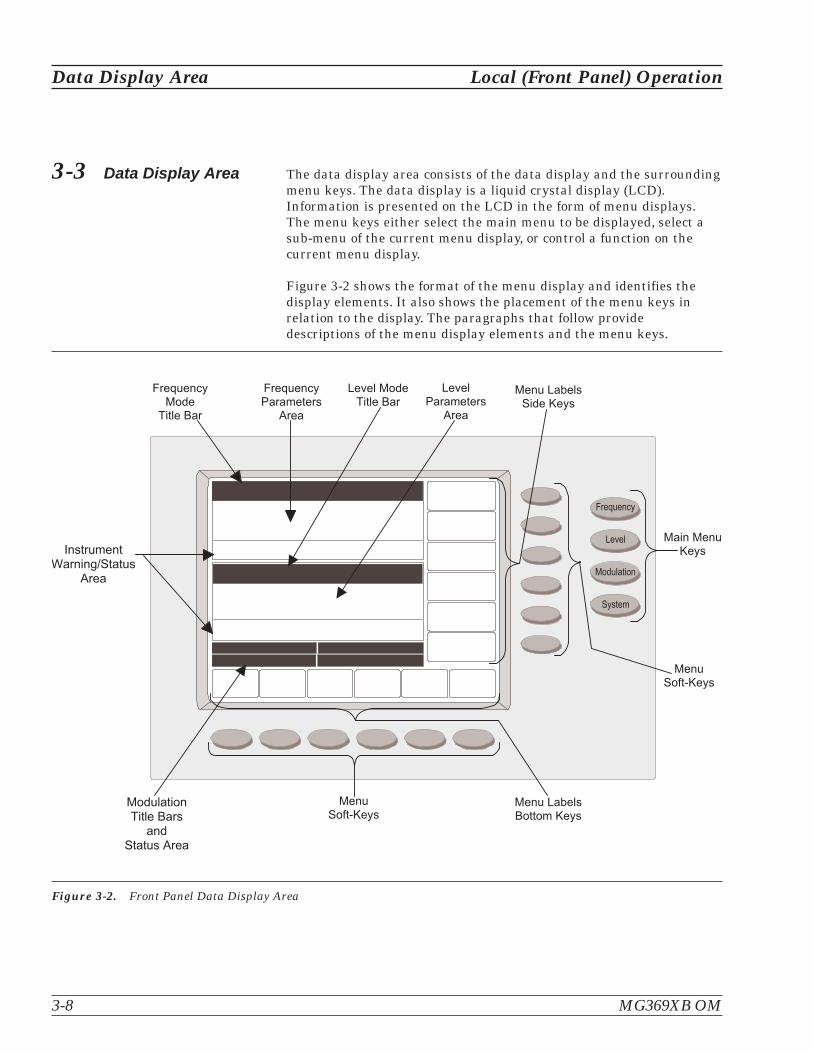
3-3 Data Display Area The data display area consists of the data display and the surroundingmenu keys. The data display is a liquid crystal display (LCD).Information is presented on the LCD in the form of menu displays.The menu keys either select the main menu to be displayed, select asub-menu of the current menu display, or control a function on thecurrent menu display.
Figure 3-2 shows the format of the menu display and identifies thedisplay elements. It also shows the placement of the menu keys inrelation to the display. The paragraphs that follow providedescriptions of the menu display elements and the menu keys.
3-8 MG369XB OM
Data Display Area Local (Front Panel) Operation
� � � � � � � � �
� � � � �
� � � � � � � �
� � � � �
� � � �! � � � � � � �
� � � � � � � �� � � �
� � � " � � � � �� � � �
# � � � � � $ �
� � � " � � � � �% � & � � � � �
' � �
� � ( � � � � � � �# � � � � � $ �
� � ( � �% � & � � � � � �
' � �
� � � � � � ) � � �$ � � � � & � � � � �
� � � � � � ) � � �! � � � � � � � �
� � � � � � � � �# � � � � � $ � �
� �! � � � � � ' � � �
� � � �! � � � � � � �
* � � � � � & � � �+ � � � � , - ! � � � �
' � � �
Figure 3-2. Front Panel Data Display Area

Menu DisplayFormat
The menu display is divided into specific areas thatshow the frequency and power level information forthe current signal generator setup. Menu labels forthe current menu's soft-keys appear along thebottom and right side of the display.
Title BarsA shaded title bar identifies each parameter area.Operation mode information is displayed on the titlebars.
� Frequency Mode Title Bar—The currentfrequency mode (CW, Step Sweep, ManualSweep, or List Sweep) appears on the left sideof the bar. In the step and list sweep mode, thetype of sweep trigger appears on the right side
� Level Mode Title Bar—The current powerlevel mode (Level or Level Sweep) appears onthe left side of the bar. In a level sweep mode,the type of sweep trigger appears on the rightside of the bar
� Modulation Title Bars—Each type of signalmodulation (AM, FM/�M, and Pulse) has aseparate title bar on the display
Parameter AreasThe parameter areas show the frequency and powerlevel information for the current MG369XB setup.
� Frequency Parameters Area—The currentCW frequency in GHz, the start and stop fre-quencies of the current frequency sweep rangein GHz, the current list index and frequency, orthe start and stop indexes for the list sweepare displayed in this area
� Power Level Parameters Area—The cur-rent power level in dBm or mV, or the startand stop levels of the current power levelsweep range in dBm or mV are displayed inthis area
� Modulation Status Areas—This area dis-plays the modulation status for the currentsetup
MG369XB OM 3-9
Local (Front Panel) Operation Data Display Area
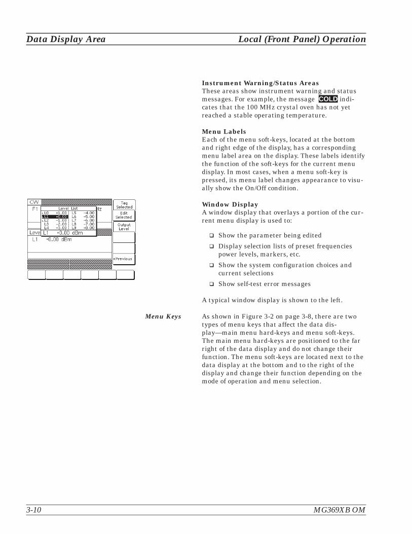
Instrument Warning/Status AreasThese areas show instrument warning and statusmessages. For example, the message COLD indi-cates that the 100 MHz crystal oven has not yetreached a stable operating temperature.
Menu LabelsEach of the menu soft-keys, located at the bottomand right edge of the display, has a correspondingmenu label area on the display. These labels identifythe function of the soft-keys for the current menudisplay. In most cases, when a menu soft-key ispressed, its menu label changes appearance to visu-ally show the On/Off condition.
Window DisplayA window display that overlays a portion of the cur-rent menu display is used to:
� Show the parameter being edited
� Display selection lists of preset frequenciespower levels, markers, etc.
� Show the system configuration choices andcurrent selections
� Show self-test error messages
A typical window display is shown to the left.
Menu Keys As shown in Figure 3-2 on page 3-8, there are twotypes of menu keys that affect the data dis-play—main menu hard-keys and menu soft-keys.The main menu hard-keys are positioned to the farright of the data display and do not change theirfunction. The menu soft-keys are located next to thedata display at the bottom and to the right of thedisplay and change their function depending on themode of operation and menu selection.
3-10 MG369XB OM
Data Display Area Local (Front Panel) Operation
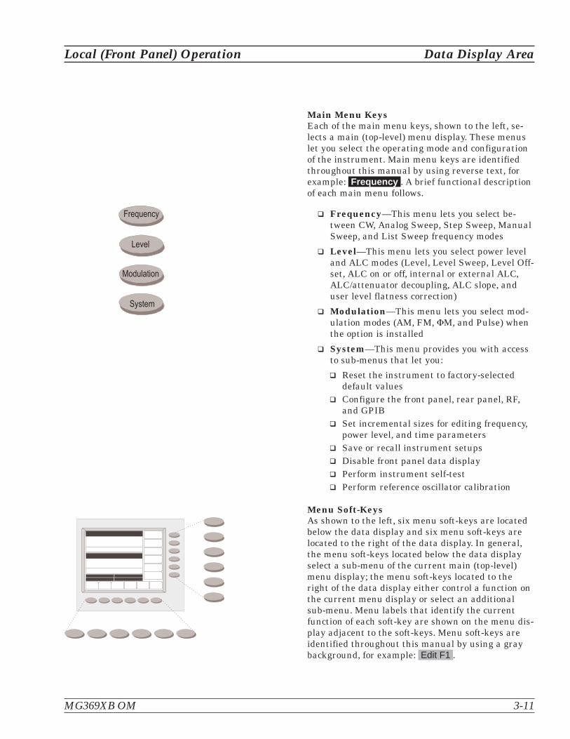
Main Menu KeysEach of the main menu keys, shown to the left, se-lects a main (top-level) menu display. These menuslet you select the operating mode and configurationof the instrument. Main menu keys are identifiedthroughout this manual by using reverse text, forexample: Frequency . A brief functional descriptionof each main menu follows.
� Frequency—This menu lets you select be-tween CW, Analog Sweep, Step Sweep, ManualSweep, and List Sweep frequency modes
� Level—This menu lets you select power leveland ALC modes (Level, Level Sweep, Level Off-set, ALC on or off, internal or external ALC,ALC/attenuator decoupling, ALC slope, anduser level flatness correction)
� Modulation—This menu lets you select mod-ulation modes (AM, FM, �M, and Pulse) whenthe option is installed
� System—This menu provides you with accessto sub-menus that let you:
� Reset the instrument to factory-selecteddefault values
� Configure the front panel, rear panel, RF,and GPIB
� Set incremental sizes for editing frequency,power level, and time parameters
� Save or recall instrument setups� Disable front panel data display� Perform instrument self-test� Perform reference oscillator calibration
Menu Soft-KeysAs shown to the left, six menu soft-keys are locatedbelow the data display and six menu soft-keys arelocated to the right of the data display. In general,the menu soft-keys located below the data displayselect a sub-menu of the current main (top-level)menu display; the menu soft-keys located to theright of the data display either control a function onthe current menu display or select an additionalsub-menu. Menu labels that identify the currentfunction of each soft-key are shown on the menu dis-play adjacent to the soft-keys. Menu soft-keys areidentified throughout this manual by using a graybackground, for example: Edit F1 .
MG369XB OM 3-11
Local (Front Panel) Operation Data Display Area
� � � � � � � � �
� � � � �
� � � � � � � �
� � � � �

3-4 Data Entry Area The value of a selected MG369XB parameter can be changed using therotary data knob, cursor control keys, or keys of the data entry area.Each element of the data entry area is identified in Figure 3-3 and de-scribed in the following paragraphs.
Cursor Control KeysIn general, this diamond-shaped key cluster controlsthe movement of the cursor on the display. When aparameter is opened for editing, a cursor appearsunder the open parameter. Each time the < or > padis pressed, the cursor moves left or right by onedigit. The � or pad can then be used to increase ordecrease the value of the parameter. The unit size ofthe increase or decrease that occurs each time the �
or pad is pressed is determined by the cursor posi-tion.
In addition, when editing frequency, power level,and time parameters, the incremental size can beset to a specific value using the systemconfiguration increment menu (page 3-84). Once setand activated, each time the � or pad is pressed,the parameter's value increases or decreases by theset amount.
3-12 MG369XB OM
Data Entry Area Local (Front Panel) Operation
� � � �� � � �
� !� � � �
" # $
% � &
' ( )
� * + , -
� � � � � �� � � � � � �� � � �
� � � �� � � � �� � �
$ � .! � �� � �
� � � � � � � � � )
� � � �
Figure 3-3. Front Panel Data Entry Area
NOTEThe cursor does not appear with the incrementmode toggled ON. The increment menu is selectedvia: System | Config | Increment > .

Rotary Data KnobThe rotary data knob can be used to change thevalue of a parameter that is open for editing. Thecursor is moved under the open parameter using the< and > cursor control keys. Then, by slowly turningthe knob clockwise or counterclockwise the value ofthe parameter is increased or decreased by the unitsize. The unit size is determined by the cursor place-ment. Turning the knob rapidly changes the value ofthe parameter in larger steps.
When editing frequency, power level, and time pa-rameters, the incremental size can be set to a spe-cific value using the system configuration incrementmenu (page 3-84). Once set and activated, each timethe knob is turned clockwise or counter-clockwise,the parameter's value increases or decreases by theset amount.
KeypadThe numeric keypad provides for entering frequency,power level, time, and number-of-steps parametersand GPIB address values. The “+/–” key functions asa “change sign” key during any keypad entry.
Clear Entry KeyWhen a parameter is open for editing, the clear en-try key is used to clear the parameter entry.
Back Space KeyThe back space key is used to correct keypad dataentry errors by deleting the last number, “–”, or deci-mal point entered.
Termination Soft-KeysTermination soft-keys are used to terminate keypaddata entries and change the parameter values inmemory. As shown on the left, termination soft-keysare located on the right side of the menu display. Ifthe entered value is outside the allowable range ofthe open parameter, an error message will be dis-played along with an audible “beep.” The frequency,time, and power level termination soft-keys are:
GHz / MHz / kHz / HzSec / ms / �s / nsdB / dBm / dB �V (in log power level mode)V / mV / �V (in linear power level mode)
MG369XB OM 3-13
Local (Front Panel) Operation Data Entry Area

3-5 Instrument Start-Up Now that you have familiarized yourself with the layout of the signalgenerator's front panel controls and data display, you are ready to be-gin operating the instrument. Begin by powering it up.
Powering Upthe MG369XB
Connect the MG369XB to an ac power source by fol-lowing the installation procedure in Chapter 2. Thisautomatically places the instrument in operation(front panel OPERATE LED on).
Start-UpDisplay
During power up, the message Please Wait...LOADING PROGRAMS appears on the data display.When all programs have been loaded, the start-upscreen (below) is displayed. It provides you with themodel number of the signal generator and the revi-sion level of the installed firmware.
The MG369XB then returns to the exact configura-tion it was in when last set to Standby.
StandbyOperation
Whenever the signal generator is not being used, itshould be left connected to the power source andplaced in standby. Standby operation provides powerto keep the internal time base at operating tempera-ture. This assures specified frequency accuracy andstability when the MG369XB is placed in operation.
NOTEDuring standby operation, the fans run contin-uously at low speed.
Press LINE (for ½ second minimum) to switch fromOPERATE (green LED) to STANDBY (orange LED).
NOTEWhen switching to operate from standby, allowat least a 30-minute warmup before beginningsignal generator operations.
3-14 MG369XB OM
Instrument Start-Up Local (Front Panel) Operation
MG3696B
RF/Microwave Signal Generator
Firmware Version 1.00
COPYRIGHT 2000 - 2004 Anritsu Co.
� � � � � � � � �
� � � �
� � � � � � � �

Self-Testingthe MG369XB
The MG369XB firmware includes internal diagnos-tics that self-test the instrument. These self-test di-agnostics perform a brief go/no-go test of most of thePCBs and other internal assemblies. If the signalgenerator fails self-test, an error message is dis-played on the data display. Error messages and de-scriptions are listed in Chapter 6—OperatorMaintenance.
You can perform a self-test of the signal generator atany time during normal operation. To perform aself-test from any menu, press System . Then, whenthe System menu (shown below) is displayed, pressSelftest .
Resetting toDefaultParameters
You can reset the MG369XB to the factory-selecteddefault parameter values at any time during normaloperation. Table 3-1, page 3-16, lists the default pa-rameters for all MG369XB models.
NOTEResetting the instrument clears the currentsetup parameters. If these parameter valuesare needed for future testing, save them as astored setup before resetting the signal genera-tor. (For information on saving/recalling instru-ment setups, refer to page 3-85.)
To reset the signal generator, press System . Whenthe System menu (above) is displayed, press Reset .
MG369XB OM 3-15
Local (Front Panel) Operation Instrument Start-Up
During self- test with RF OUTPUT set to ON, the outputpower level is set to 0 dBm. Always disconnect sensitiveequipment from the unit before performing self-test.
CAUTION

3-16 MG369XB OM
Instrument Start-Up Local (Front Panel) Operation
MODELNUMBER
FREQUENCY PARAMETERS (GHz)
F0 F1 F2 F3 F4 F5 F6 F7 F8 F9 M0 M1 M2 M3 M4 M5 M6 M7 M8 M9 �F
MG3691B 3.5 2.0* 8.4 2.0* 5.0 8.0 8.4 8.4 8.4 8.4 3.5 2.0* 8.4 2.0* 5.0 8.0 8.4 8.4 8.4 8.4 1.0
MG3692B 3.5 2.0* 20.0 2.0* 5.0 8.0 11.0 14.0 17.0 20.0 3.5 2.0* 20.0 2.0* 5.0 8.0 11.0 14.0 17.0 20.0 1.0
MG3693B 3.5 2.0* 30.0 2.0* 5.0 8.0 11.0 14.0 17.0 20.0 3.5 2.0* 30.0 2.0* 5.0 8.0 11.0 14.0 17.0 20.0 1.0
MG3694B 3.5 2.0* 40.0 2.0* 5.0 8.0 11.0 14.0 17.0 20.0 3.5 2.0* 40.0 2.0* 5.0 8.0 11.0 14.0 17.0 20.0 1.0
MG3695B 3.5 2.0* 50.0 2.0* 5.0 8.0 11.0 14.0 17.0 20.0 3.5 2.0* 50.0 2.0* 5.0 8.0 11.0 14.0 17.0 20.0 1.0
MG3696B 3.5 2.0* 67.0 2.0* 5.0 8.0 11.0 14.0 17.0 20.0 3.5 2.0* 67.0 2.0* 5.0 8.0 11.0 14.0 17.0 20.0 1.0
* 2.2 GHz for units with Option 4
Table 3-1. Reset (Default) Parameters
MODELNUMBER
POWER LEVEL PARAMETERS (dBm)
L0 L1 L2 L3 L4 L5 L6 L7 L8 L9
MG3691B +1.0 0.0 –1.0 –2.0 –3.0 –4.0 –5.0 –6.0 –7.0 –8.0
MG3692B +1.0 0.0 –1.0 –2.0 –3.0 –4.0 –5.0 –6.0 –7.0 –8.0
MG3693B +1.0 0.0 –1.0 –2.0 –3.0 –4.0 –5.0 –6.0 –7.0 –8.0
MG3694B +1.0 0.0 –1.0 –2.0 –3.0 –4.0 –5.0 –6.0 –7.0 –8.0
MG3695B +1.0 0.0 –1.0 –2.0 –3.0 –4.0 –5.0 –6.0 –7.0 –8.0
MG3696B +1.0 0.0 –1.0 –2.0 –3.0 –4.0 –5.0 –6.0 –7.0 –8.0
MODELNUMBER
SWEEPTIME
STEP SWEEP LEVEL SWEEPLEVEL
OFFSETDWELL TIME
NUMBER OFSTEPS
DWELL TIMENUMBER OF
STEPS
MG3691B 50 ms 1 ms 50 50 ms 50 0.0 dB
MG3692B 50 ms 1 ms 50 50 ms 50 0.0 dB
MG3693B 50 ms 1 ms 50 50 ms 50 0.0 dB
MG3694B 50 ms 1 ms 50 50 ms 50 0.0 dB
MG3695B 50 ms 1 ms 50 50 ms 50 0.0 dB
MG3696B 50 ms 1 ms 50 50 ms 50 0.0 dB

3-6 Entering Data Before proceeding to the various modes of signal generator operation,you need to know how to enter data from the front panel. Enteringdata refers to changing a parameter's value by editing its currentvalue or entering a new value to replace the current value. The follow-ing instructions describe how to (1) open a parameter, (2) edit its cur-rent value, and (3) enter a new value.
A typical MG369XB menu display (below) is used throughout the dataentry instructions. At this menu display, you can edit both the CW fre-quency and the output power level parameters.
If you wish to follow along on your MG369XB, you can obtain thissame menu display by resetting your instrument (press System , thenpress Reset ).
Opening theParameter
In order for the value of a parameter to be changed,the parameter must first be opened.
To open the frequency parameter from the abovemenu, press Edit F1 . The menu display changes(below) to show that the menu soft-key Edit F1 hasbeen pressed and that the frequency parameter hasbeen opened. An open parameter is indicated byplacing it in a window with a movable cursor underits digits. If the cursor is not displayed, you must de-activate increment mode (refer to page 3-84).
MG369XB OM 3-17
Local (Front Panel) Operation Entering Data
Only one parameter can be open at a time. If youpress Edit L1 , then the frequency parameter willclose and the power level parameter will open.
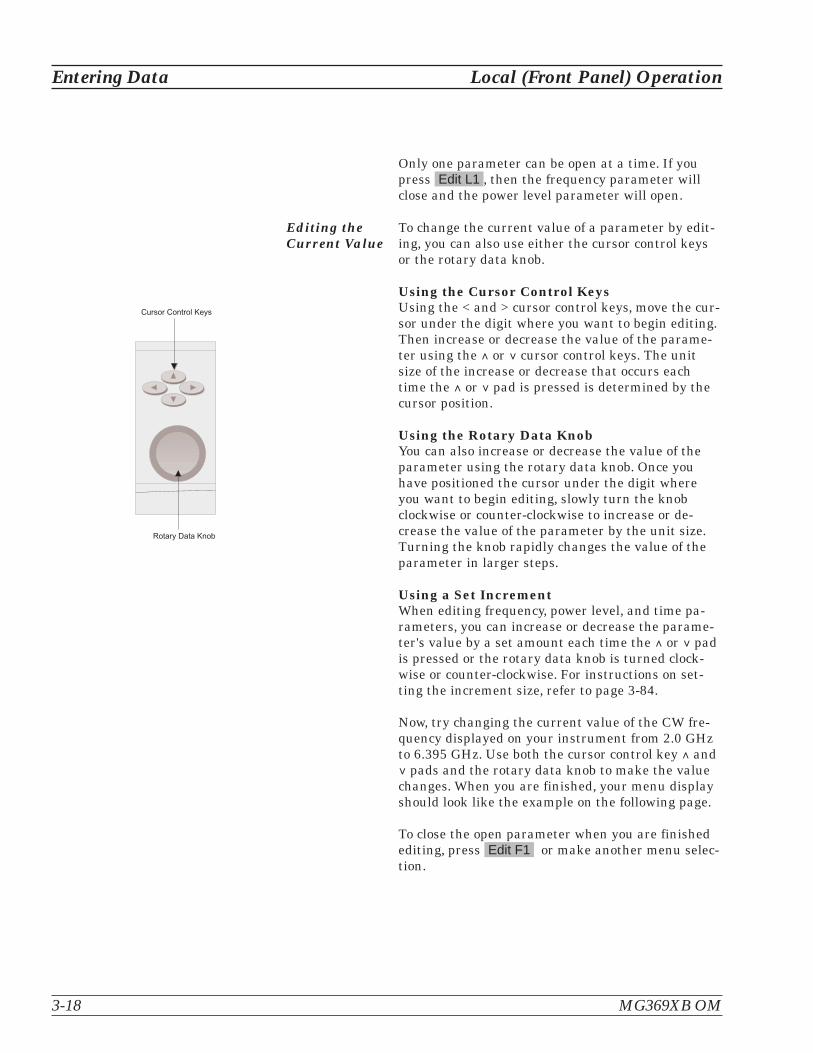
Editing theCurrent Value
To change the current value of a parameter by edit-ing, you can also use either the cursor control keysor the rotary data knob.
Using the Cursor Control KeysUsing the < and > cursor control keys, move the cur-sor under the digit where you want to begin editing.Then increase or decrease the value of the parame-ter using the � or cursor control keys. The unitsize of the increase or decrease that occurs eachtime the � or pad is pressed is determined by thecursor position.
Using the Rotary Data KnobYou can also increase or decrease the value of theparameter using the rotary data knob. Once youhave positioned the cursor under the digit whereyou want to begin editing, slowly turn the knobclockwise or counter-clockwise to increase or de-crease the value of the parameter by the unit size.Turning the knob rapidly changes the value of theparameter in larger steps.
Using a Set IncrementWhen editing frequency, power level, and time pa-rameters, you can increase or decrease the parame-ter's value by a set amount each time the � or padis pressed or the rotary data knob is turned clock-wise or counter-clockwise. For instructions on set-ting the increment size, refer to page 3-84.
Now, try changing the current value of the CW fre-quency displayed on your instrument from 2.0 GHzto 6.395 GHz. Use both the cursor control key � and pads and the rotary data knob to make the valuechanges. When you are finished, your menu displayshould look like the example on the following page.
To close the open parameter when you are finishedediting, press Edit F1 or make another menu selec-tion.
3-18 MG369XB OM
Entering Data Local (Front Panel) Operation
� � � � � � � � � � � )
� � � � � � � � � � � � � � � � � � �

Entering aNew Value
To change the current value of a parameter by en-tering a new value for the parameter, use the dataentry keypad and termination keys.
As soon as you press one of the keys on the data en-try keypad, the current parameter display clears forentry of a new value. Enter the new value for theparameter, then press the appropriate terminatorsoft-key to store it in memory. If the entered value isoutside the allowable range of the open parameter,the entry is not accepted and the previous value forthe parameter is displayed.
If you make an error during data entry, either (1)press Back Space to delete the entry one characterat a time starting from the last character entered, or(2) delete the entire entry by pressing Clear Entry .Then, re-enter the correct value.
Now, try entering a new value for the CW frequencydisplayed on your MG369XB using the data entrykeypad and termination soft-keys.
To close the open parameter when you are finishedentering data, press Edit F1 or make another menuselection.
MG369XB OM 3-19
Local (Front Panel) Operation Entering Data
� � � �� � � �
� !� � � �
" # $
% � &
' ( )
� * + , -
� � � �
� � � �� � � � �� � �
$ � .! � �� � �
NOTEA frequency entry may be termi-nated in GHz, MHz, kHz, or Hz;however, it is always displayed onthe data display in GHz. A time en-try may be terminated in Sec, ms,�s, or ns; however, it is always dis-played on the data display in Sec.

3-7 CW FrequencyOperation
One of the signal generator's major functions is to produce discreteCW frequencies across the frequency range of the instrument. The fol-lowing paragraphs describe how to place the MG369XB in the CW fre-quency mode, select a CW frequency and power level for output, andactivate the CW ramp and Phase Offset menus and functions. Use theCW Frequency Mode menu map (Chapter 4, Figure 4-2) to follow themenu sequences.
Selecting CWMode
To place the MG369XB in the CW frequency mode,press Frequency . At the resulting menu display,press CW . The CW menu (below) is displayed.
This menu lets you perform the following:
� Select a CW frequency for output
� Copy the current frequency and power level in-formation to the current list index. (Refer topage 3-42 for the list sweep frequency mode op-erating instructions)
� Access the master-slave menu. (Refer topage 7-4 for Master-Slave mode operating in-structions)
� Select an output power level for the CW fre-quency
� Select the Phase Offset menu
� Select the CW Ramp menu
Selecting aCW Frequency
There are several ways to select a CW frequency foroutput. You can (1) edit the current frequency, (2)enter a new frequency, or (3) select one of the 20 pre-set frequency parameters.
3-20 MG369XB OM
CW Frequency Operation Local (Front Panel) Operation
NOTEWhen the signal generator is reset,it automatically comes up operat-ing in the CW frequency mode.

Editing the Current FrequencyPress Edit F1 [F1] to open the frequency parameter,then edit the current CW frequency using the cursorcontrol keys or the rotary data knob. To close theopen frequency parameter, press Edit F1 or makeanother menu selection.
Entering a New FrequencyPress Edit F1 [F1] to open the frequency parameter,then enter the new CW frequency using the keypadand appropriate terminator key. To close the openfrequency parameter, press Edit F1 or make an-other menu selection.
Selecting a Preset FrequencyTo select one of the preset frequencies for output,press the soft-key Frequency Control > . The CWFrequency Control menu, shown below, is displayed.
This menu lets you perform the following:
� Select preset frequencies F0 [CF0], F1 [CF1], F2[CF2], M1 [CM1], or M2 [CM2] for output
� Edit each preset frequency
� Access the Frequency List menu (to tag, edit,or output a frequency from the list)
� Select a tagged frequency from the frequencylist (tagging is described below) for output us-ing the Scan Up or Scan Down keys
� Select an output power level for the CW fre-quency
Press < Previous to return to the CW menu display.
MG369XB OM 3-21
Local (Front Panel) Operation CW Frequency Operation

Frequency List—To access the Frequency Listmenu (below), press Frequency List... from the Fre-quency Control menu. This menu lets you tag, edit,or output a frequency from the list.
Use the cursor control keys to select a frequencyfrom the frequency list. The selected frequency ishighlighted in reverse video and displayed in full be-low the frequency list.
Press Tag Selected to tag a selected frequency(places an F in front of the tagged frequency). If thefrequency is already tagged, pressing Tag Selectedwill un-tag the frequency (remove the F). Taggingselected frequencies lets you quickly switch betweenthem using the scan soft-keys of the CW FrequencyControl menu.
Press Edit Selected to edit the selected frequency orenter a new frequency.
Press Output Frequency to output the selected fre-quency. On the frequency list, the output frequencyselection is marked by (a black square) or, iftagged, an F (highlighted in reverse video). Thisfrequency is output until you select another fre-quency from the list and press Output Frequency .
Return to the CW Frequency Control menu displayby pressing < Previous .
Selecting aPower Level
While in the CW frequency mode, you can edit thecurrent CW frequency output power level or enter anew output power level.
3-22 MG369XB OM
CW Frequency Operation Local (Front Panel) Operation

Editing the Current Power LevelPress Edit L1 [XL1] to open the power level parame-ter, then edit the current power level using the cur-sor control keys or rotary data knob. To close theopen power level parameter, press Edit L1 or makeanother menu selection.
Entering a New Power LevelPress Edit L1 [XL1] to open the power level parame-ter, then enter the new power level using the keypadand appropriate terminator key. To close the openpower level parameter, press Edit L1 or make an-other menu selection.
NOTEYou can also select any of the preset power lev-els or a power level sweep for a CW frequency.For instructions, refer to Section 3-9 (FixedPower Level Operation) and Section 3-10(Power Level Sweep Operation).
CW Ramp When active, the MG369XB's CW ramp provides arepetitive 0V to 10V ramp output to the rear panelHORIZ OUT BNC connector and AUX I/O connector,pin 1. The CW ramp is used to drive a scalar ana-lyzer display.
To turn on the CW ramp from the CW menu, pressCW Ramp> to access the CW Ramp menu (below)
and press CW Ramp [CS1].
While the CW ramp is on, the message CW Rampappears on the right side of the frequency title baron all CW menus.
Press CW Ramp [CS0] again to turn the CW rampoff.
MG369XB OM 3-23
Local (Front Panel) Operation CW Frequency Operation

Phase Offset When active, the MG369XB's RF output will bephase shifted by the specified amount displayed inthe phase offset parameter. The phase offset rangeis -360� to +360� with a resolution of 0.1�.
NOTEThe phase offset function is available in CW op-erating mode only.
To activate the phase offset from the CW menu,press Phase Offset> to access the Phase Offsetmenu (below) and press Phase Offset [PS1].
To turn off the phase offset, press Phase Offset .[PS0] from the phase offset menu.
To edit the phase offset value, press Edit Offset[PSO] button from the phase offset menu (below),then use the cursor keys or rotary knob to edit thephase offset or use the keypad to enter a new value.
Press Edit Offset to close the open parameter.
3-24 MG369XB OM
CW Frequency Operation Local (Front Panel) Operation

While the phase offset is on, the phase offset valueis displayed in the CW menu (below).
The phase offset value may be zeroed. This allowsyou to normalize the phase offset display as appro-priate.
To zero the phase offset display from the phase off-set menu, press Zero Display [PSZ] (below).
NOTEAdjusting the phase offset zero display does notaffect the phase shift of the RF output.
ElectronicFrequencyControl
Additional frequency control is provided by the Elec-tronic Frequency Control circuit via the EFC INBNC connector on the rear panel. This circuit pro-vides an external dc feedback point and the capabil-ity to frequency modulate the internal referencecrystal oscillator. This allows phase locking of thesignal generator’s RF output by means of an exter-nal phase locked loop. Refer to Appendix A, RearPanel Connectors, for more information.
MG369XB OM 3-25
Local (Front Panel) Operation CW Frequency Operation

3-8 Sweep FrequencyOperation
The signal generator can generate broad (full range) and narrow bandsweeps across the frequency range of the instrument. The MG369XBhas four sweep frequency modes—analog sweep, step sweep, manualsweep, and list sweep. Descriptions and operating instructions for theanalog sweep frequency mode begins on this page. Step sweep fre-quency mode descriptions and operating instructions begin onpage 3-28. Manual sweep frequency mode descriptions and operatinginstructions begin on page 3-32. List sweep frequency mode descrip-tions and operating instructions begin on page 3-42. Use the AnalogSweep, Step Sweep, Manual Sweep, and List Sweep frequency modemenu maps (Chapter 4, Figures 4-3, through 4-6) to follow the menusequences.
Analog SweepMode
In analog sweep frequency mode, the MG369XB'soutput frequency is swept between selected startand stop frequencies. Sweep width can be set from1 MHz to the full frequency range of the signal gen-erator. Sweep time can be set for any time in therange of 30 ms to 99 sec. The lower frequency limitfor analog sweeps is 10 MHz (500 MHz with Op-tion 4).
When the sweep width of the analog sweep is>100 MHz, the sweep is phase-lock corrected at boththe start and stop frequencies and at each bandswitch point. When the sweep width is �100 MHz,only the center frequency is phase-lock corrected.
SelectingAnalog SweepMode
To place the MG369XB in analog sweep frequencymode, press Frequency . At the resulting menu dis-play, press Analog Sweep [SWP]. The AnalogSweep menu (below) is then displayed.
3-26 MG369XB OM
Sweep Frequency Operation Local (Front Panel) Operation

This menu lets you perform the following:
� Select a sweep range
� Set the sweep time
� Access the Trigger menu
� Select an output power level for the sweep
� Access the Alternate Sweep menu
Setting SweepTime
To set the analog sweep time, from the AnalogSweep menu, press Sweep Time [SWT].
Edit the current sweep time using the cursor controlkeys, the rotary data knob, or enter a new sweeptime using the key pad and appropriate terminationkey. To close the open sweep time parameter onceyou have set the desired sweep time, pressSweep Time or make another menu selection.
To access the Analog Sweep Trigger menu from thismenu, press Trigger > . From the Trigger menu, youcan select one of three trigger modes:
� Auto
� External
� Single
The trigger modes are described on page 3-31.
To access the Alternate Sweep menu, pressAlternate Sweep > . The Alternate Sweep modes are
described on page 3-38.
Press < Previous to return to the Analog Sweepmenu display.
MG369XB OM 3-27
Local (Front Panel) Operation Sweep Frequency Operation

Step SweepMode
In step sweep frequency mode, the output frequencychanges in discrete, synthesized steps between theselected start and stop frequencies. Step sweeps canbe from a low frequency to a high frequency andfrom a high frequency to a low frequency. Stepsweeps can be selected to be linear or logarithmic.The sweep width can be set from 0.01 Hz to the fullfrequency range of the instrument.
The step size or number of steps between the sweepstart and stop frequencies, the dwell-time-per-step,the sweep time, the type of step sweep (linear or log-arithmic), and sweep trigger are controllable fromstep sweep menus.
Selecting StepSweep Mode
To place the MG369XB in step sweep frequencymode, press Frequency . At the resulting menu dis-play, press Step Sweep [SSP]. The Step Sweepmenu (below) is then displayed.
This menu lets you perform the following:
� Select a sweep range (edit the sweep start andstop frequency parameters)
� Set the dwell-time-per-step
� Set the step size
� Select an output power level for the sweep
� Access the additional step sweep menu (set thesweep time, set the number of steps, access theTrigger menu, select log or linear sweep, andaccess the alternate sweep menu)
3-28 MG369XB OM
Sweep Frequency Operation Local (Front Panel) Operation

Setting StepSize, DwellTime, andSweep Time
In linear step sweep, the sweep is linearly incre-mented (or decremented) by the step size from thestart frequency to the stop frequency. There are twoways to set the size of each step of the linear stepsweep—set the step size or set the number of steps.The step size range is 0.01 Hz to the full frequencyrange of the instrument; the number of steps rangeis 1 to 10,000. If the step size does not divide intothe frequency range, the last step is truncated.
In logarithmic step sweep, step size increases loga-rithmically with the frequency and is determined bya logarithmic curve between the sweep start andstop frequencies and the number of steps. Thenumber of steps can range from 1 to 10,000.
The dwell-time-per-step of the step sweep can be setfor any time in the range of 1 ms to 99 sec. Whendwell-time-per-step, step size or number of steps isset, the sweep time equals dwell-time-per-step timesthe number of steps plus the total phase-lockingtime for all the step frequencies. If sweep time is set,then dwell-time-per-step is the result of the sweeptime divided by the number of steps. In this case,the resultant minimum dwell time must be �10 msto allow for phase-locking of each step frequency.The sweep time of the step sweep can be set for anytime in the range of 20 ms to 99 sec.
Press Dwell Time [SDT] to open the dwell time-per-step parameter.
Press Step Size [SYZ] to open the step size parame-ter.
Open the parameter you wish to change, then editthe current value using the cursor control keys, therotary data knob or enter a new value using the keypad and appropriate termination soft-key. When youhave finished setting the open parameter, close it bypressing its menu soft-key or make another menuselection.
MG369XB OM 3-29
Local (Front Panel) Operation Sweep Frequency Operation

Press More > to access the Additional Step Sweepmenu (below).
This menu lets you perform the following:
� Set the sweep time
� Set the number of steps
� Access the Trigger menu
� Select log or linear sweep
� Access the Alternate Sweep menu
Press Sweep Time [SWT] to open the sweep timeparameter.
Press Num of Steps [SNS] to open the number ofsteps parameter.
Open the parameter you wish to change, then editthe current value using the cursor control keys, therotary data knob, or enter a new value using the keypad and appropriate termination soft-key. When youhave finished setting the open parameter, close it bypressing its menu soft-key or make another menuselection.
Press Trigger > to access the Step Sweep Triggermenu. The trigger menu lets you select the followingsweep trigger modes:
� Auto
� External
� Single
The trigger modes are described on page 3-31.
3-30 MG369XB OM
Sweep Frequency Operation Local (Front Panel) Operation
RANGE
This error message is displayedwhen (1) the step size value enteredis greater than the sweep range, (2)the number of steps entered resultsin a step size of less than 0.01 Hz, or(3) the sweep time entered dividedby the number of steps entered re-sults in a dwell time of <10 ms. En-tering valid values will clear the er-ror.

To access the Alternate Sweep menu, pressAlternate Sweep > . The Alternate Sweep modes are
described on page 3-38.
Press Log/Linear [LGS/LIS] to select logarithmic orlinear step sweep operation. The soft-key label ishighlighted (in reverse video) to reflect your selec-tion.
Press < Previous to return to the Step Sweep menudisplay.
Selecting aSweep Trigger
There are three modes of sweep triggering for ana-log and step frequency sweep—automatic, external,and single. The sweep trigger is selectable from thetrigger menu. The following is a description of eachmode:
� Auto (Automatic)–The sweep continuallysweeps from its start frequency to its stop fre-quency with optimal retrace time
� External–The sweep recurs when triggered byan external TTL-compatible clock pulse to therear panel AUX I/O connector
� Single–A single sweep starts when the triggerkey is pressed. If a sweep is in progress whenthe key is pressed, it aborts and resets
MG369XB OM 3-31
Local (Front Panel) Operation Sweep Frequency Operation
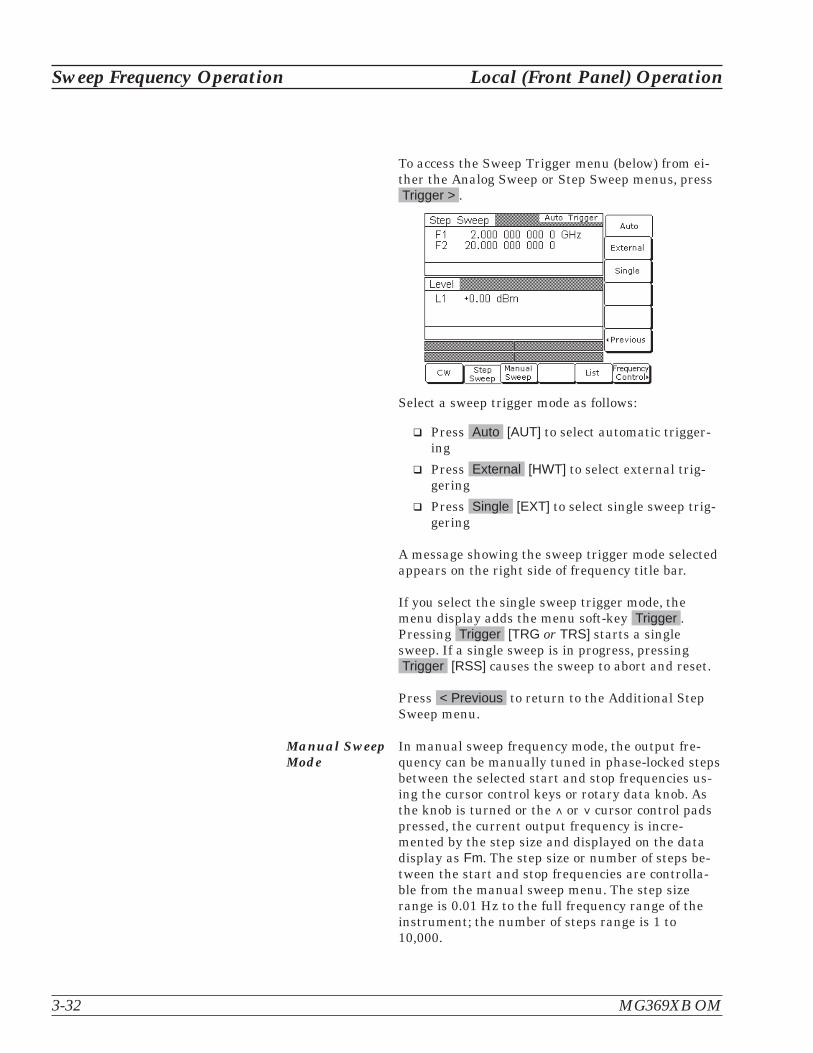
To access the Sweep Trigger menu (below) from ei-ther the Analog Sweep or Step Sweep menus, pressTrigger > .
Select a sweep trigger mode as follows:
� Press Auto [AUT] to select automatic trigger-ing
� Press External [HWT] to select external trig-gering
� Press Single [EXT] to select single sweep trig-gering
A message showing the sweep trigger mode selectedappears on the right side of frequency title bar.
If you select the single sweep trigger mode, themenu display adds the menu soft-key Trigger .Pressing Trigger [TRG or TRS] starts a singlesweep. If a single sweep is in progress, pressingTrigger [RSS] causes the sweep to abort and reset.
Press < Previous to return to the Additional StepSweep menu.
Manual SweepMode
In manual sweep frequency mode, the output fre-quency can be manually tuned in phase-locked stepsbetween the selected start and stop frequencies us-ing the cursor control keys or rotary data knob. Asthe knob is turned or the � or cursor control padspressed, the current output frequency is incre-mented by the step size and displayed on the datadisplay as Fm. The step size or number of steps be-tween the start and stop frequencies are controlla-ble from the manual sweep menu. The step sizerange is 0.01 Hz to the full frequency range of theinstrument; the number of steps range is 1 to10,000.
3-32 MG369XB OM
Sweep Frequency Operation Local (Front Panel) Operation

SelectingManual SweepMode
To place the MG369XB in manual sweep frequencymode, press Frequency . At the resulting menu dis-play, press Manual Sweep [MAN]. The ManualSweep menu (below) is then displayed.
This menu lets you perform the following:
� Select a sweep range (edit the start and stopfrequency parameters)
� Set the step size or number of steps (previouslydescribed on page 3-29)
Selecting aSweep Range
Selecting a sweep range involves choosing a startand a stop frequency for the frequency sweep. Thesweep range selection process is identical for thestep, analog and manual sweep frequency modes.There are several ways you can select a sweeprange, including:
� Editing the current start and stop frequencyparameter values
� Entering new start and stop frequency pa-rameter values
� Selecting one of the preset sweep range pa-rameters (F1-F2, F3-F4, F5-dF, or F6-dF)
MG369XB OM 3-33
Local (Front Panel) Operation Sweep Frequency Operation

Editing the Current Start / Stop FrequenciesTo edit the current frequency sweep range, open ei-ther the start or stop frequency parameter. In thedisplay above, Edit F1 [F1] opens the start fre-quency parameter; Edit F2 [F2] opens the stop fre-quency parameter.
Edit the open frequency parameter using the cursorcontrol keys or the rotary data knob. When you arefinished, close the open parameter by pressing itsmenu edit soft-key or by making another menu se-lection.
Entering New Start / Stop FrequenciesTo enter a new frequency sweep range, open eitherthe start or stop frequency parameter (press Edit F1[F1] or Edit F2 [F2]).
Enter a new frequency using the keypad and appro-priate termination soft-key. When you are finished,close the open parameter by pressing its menu editsoft-key or by making another menu selection.
Selecting a Preset Sweep RangeThere are four preset sweep range parameters, se-lectable in the analog sweep, step sweep, and man-ual sweep frequency modes. The following is adescription of each preset sweep range.
� F1-F2 [SF1] –provides a frequency sweep be-tween the start frequency, F1, and the stop fre-quency, F2
� F3-F4 [SF3]–provides a frequency sweep be-tween the start frequency, F3, and the stop fre-quency, F4
� F5-dF [DF5]–provides a symmetrical frequencysweep about the center frequency, F5. Thesweep width is determined by the dF frequencyparameter
� F6-dF [DF6]–provides a symmetrical frequencysweep about the center frequency, F6. Thesweep width is determined by the dF frequencyparameter
3-34 MG369XB OM
Sweep Frequency Operation Local (Front Panel) Operation
RANGE
This error message is displayedwhen the dF value entered resultsin a sweep outside the range of theMG369XB. Entering a valid valuewill clear the error.

To select one of the preset sweep ranges from anysweep frequency mode menu, press the soft-keyFrequency Control > . The Sweep Frequency Control
menu (below) is displayed.
This menu lets you perform the following:
� Select a full range sweep (Fmin to Fmax) [FUL]or one of the preset sweep ranges for the sweepfrequency mode
� Select the frequency parameters for each pre-set sweep range
� Access the marker list menu (described onpage 3-36)
� Select an output power level for the sweep
Setting a Preset Sweep RangeAt the Sweep Frequency Control menu, select thesweep range (F1-F2, F3-F4, F5-dF, or F6-dF) that youwish to set. The menu then displays the current fre-quency parameters for the selected sweep range.Now, use the menu edit soft-keys to open the fre-quency parameters for editing.
Edit the current frequency parameters or enter newfrequency parameter values for the sweep range. Toclose the open frequency parameter when you arefinished, press its menu edit soft-key or make an-other menu selection.
You can set all the preset sweep ranges in this man-ner.
MG369XB OM 3-35
Local (Front Panel) Operation Sweep Frequency Operation

Selecting aPower Level
While at the Sweep Frequency Control menu, youcan edit the current output power level or enter anew output power level for the frequency sweep.
Editing the Current Power LevelPress Edit L1 [XL1] to open the power level parame-ter, then edit the current power level using the cur-sor control keys or rotary data knob. To close theopen power level parameter, press Edit L1 or makeanother menu selection.
Entering a New Power LevelPress Edit L1 [XL1] to open the power level parame-ter, then enter the new power level using the keypadand appropriate termination soft-key. To close theopen power level parameter, press Edit L1 or makeanother menu selection.
NOTEYou can also select any of the preset power lev-els for a frequency sweep or a power level stepfor a step sweep. For instructions, refer topage 3-51 (Fixed Power Level Operation) andpage 3-56 (Power Level Sweep Operation).
FrequencyMarkers
The signal generator provides up to 20 independent,pre-settable markers, F0-F9 and M0-M9, that can beused in the step sweep frequency mode for precisefrequency identification. Marker frequency accuracyis the same as sweep frequency accuracy. The mark-ers are visible on a CRT display.
The MG369XB generates two types of markers:
� Video Marker–produces a pulse on a CRTdisplay at each marker frequency. The videomarker is either a +5V or a –5V pulse avail-able at the rear panel AUX I/O connector. Themarker’s pulse polarity is selectable from theSystem Configuration menu, page 3-78
� Intensity Marker–produces an intensifieddot on a CRT display at each marker fre-quency. They are obtained by a momentarydwell in the sweep at each marker frequency.Intensity markers are only available in the an-alog sweep frequency mode at sweep times of<1 second
3-36 MG369XB OM
Sweep Frequency Operation Local (Front Panel) Operation

To output markers during a sweep you must first se-lect (tag) the marker frequencies from the MarkerList menu, then turn on the marker output.
To access the Marker List menu from a sweep fre-quency menu, press Frequency Control > . TheSweep Frequency Control menu (below) is dis-played.
Now press the menu soft-key Marker List... . TheMarker List menu (below) is displayed.
This menu lets you tag or edit marker list frequen-cies and turn the markers on/off.
Use the cursor control keys to select a frequency pa-rameter from the marker list. The selected fre-quency parameter is highlighted in reverse videoand displayed in full below the marker list.
Editing a Marker List FrequencyIf you want to change a selected marker list fre-quency parameter's value, press Edit Selected toopen the frequency parameter, then edit the currentfrequency or enter a new frequency.
MG369XB OM 3-37
Local (Front Panel) Operation Sweep Frequency Operation

Tagging a Marker List FrequencyOnly frequencies on the marker list that have beentagged can be output as markers during a sweep.Press Tag to tag a selected frequency parameter(place an m in front of it). If a frequency parameteris already tagged, pressing Tag will un-tag the fre-quency parameter (remove the m).
Activating MarkersPress Video Markers [VM1] to output the taggedmarker frequencies as video markers during a stepsweep. Video markers will be displayed on the CRTfor all tagged marker frequencies that are withinthe sweep frequency range.
To turn the markers off, press Video Markers [MK0]again.
Press < Previous to return to the Sweep FrequencyControl menu display.
SelectingAlternateSweep Mode
In alternate sweep frequency mode, the signal gen-erator's output frequency sweeps alternately be-tween any two sweep ranges in step sweep.
NOTEThe following procedure applies for both stepsweep mode and analog sweep mode.
To select the alternate sweep mode from the StepSweep menu display, press More > to access the Ad-ditional Step Sweep menu display (below).
3-38 MG369XB OM
Sweep Frequency Operation Local (Front Panel) Operation

From here or from the Analog Sweep menu, pressAlternate Sweep > to access the Alternate Sweepmenu display (below).
This menu lets you perform the following:
� Turn the alternate sweep mode on/off
� Access the alternate range menu to select asweep range for the alternate sweep
� Access the alternate level menu to select apower level for the alternate sweep
Activating the Alternate SweepThe soft-key Alternate Sweep toggles the alternatesweep mode on and off.
Press Alternate Sweep to turn on the alternatesweep mode. Notice that the Alternate Sweep menu(below) changes to show that the alternate sweep isnow active.
MG369XB OM 3-39
Local (Front Panel) Operation Sweep Frequency Operation

Selecting an Alternate Sweep RangePress Alternate Range > to access the AlternateRange menu display (below).
Select the alternate sweep range (Full [AFU], F1-F2[AF1], F3-F4 [AF3], F5-dF [AD5], or F6-dF [AD6]). Themenu then displays the current frequency parame-ters for the selected sweep range. If you wish tochange a frequency parameter, use the menu editsoft-key to open the parameter, then edit it.
When you are done selecting the alternate sweeprange, press < Previous to return to the AlternateSweep menu display.
3-40 MG369XB OM
Sweep Frequency Operation Local (Front Panel) Operation

Selecting an Alternate Sweep Power LevelPress Alternate Level > to access the AlternateLevel menu display (below).
Select the power level for the alternate sweep range(L0 [AL0], L1 [AL1], L2 [AL2], L3 [AL3], or L4 [AL4]).The menu then displays the current level parameterfor the selected power level. If you wish to changethe level, press Edit L2 to open the parameter, thenedit it.
The Edit L1 soft-key is provided to let you changethe power level of the main sweep.
When you are done selecting the power level for thealternate sweep range and editing the power level ofthe main sweep, press < Previous to return to theAlternate Sweep menu display.
MG369XB OM 3-41
Local (Front Panel) Operation Sweep Frequency Operation
Performing alternate sweeps using power levels that crossstep attenuator switch points can cause excessive wear onthe switches and reduce the life expectancy of the stepattenuator.
CAUTION

List SweepMode
In list sweep frequency mode, the output is a stepsweep of up to 2000 phase-locked, non-sequentialfrequencies. Each frequency can have a differentpower level setting. The list index (0 through 1999)identifies each frequency/power level set in the list.The list sweep is defined by a list start index andlist stop index.
There are four modes of sweep triggering in listsweep—automatic, external, single, and manual.When automatic, external, or single trigger mode isselected, the output sweeps between the specifiedlist start and stop indexes, dwelling at each list in-dex for the specified dwell time. When manual trig-ger mode is selected, the list start index, list stopindex, and dwell time parameter are not used. In-stead, the list index is incremented or decrementedby using the front panel cursor control keys. In man-ual trigger mode, the list index can also be incre-mented by using an external trigger input. EachTTL trigger increments the list index by one.
After a reset, the list sweep defaults to manual trig-ger mode. The data display shows the trigger mode,list index, current frequency, and current powerlevel. The list index specifies the current locationwithin the list. The current frequency is preceded bythe text “Fr”. The current power level is preceded bythe text “Lv”. When automatic, external, or singletrigger mode is selected, the data display changes toshow the trigger mode and list sweep start and stopindex values only.
The list of up to 2000 frequency/power level sets isstored in non-volatile RAM to preserve any settingsafter the instrument is powered off. The list is notstored with the other setup information in the in-strument. After a master reset, the list is reset to itsdefault state of 2000 index entries of 5 GHz at0 dBm.
3-42 MG369XB OM
Sweep Frequency Operation Local (Front Panel) Operation

Selecting ListSweep Mode
To place the MG369XB in list sweep frequencymode, press Frequency . At the resulting menu dis-play, press List [LST]. The List Sweep menu (below)is displayed.
This menu lets you perform the following:
� Access the Frequency List menu (edit list in-dex frequency parameters and insert and de-lete list index entries)
� Access the Power List menu (edit list indexpower level parameters and insert and deletelist index entries)
� Edit the list index parameter
� Calculate all list index frequency and powerlevel settings
� Access the Sweep menu (set sweep start index,stop index, and dwell time and select a sweeptrigger)
� Edit the current list index frequency, Fr
Editing the List IndexPress Edit List Index [ELI(xxxx)] to open the list in-dex parameter for editing. Edit the current list in-dex value using the cursor control keys, rotary dataknob, or enter a new value using the key pad andtermination soft-key. When you have finished set-ting the open parameter, close it by pressingEdit List Index again or by making another menu
selection.
MG369XB OM 3-43
Local (Front Panel) Operation Sweep Frequency Operation

The Edit List Index soft-key is not the only way tochange the list index. In the list sweep mode withmanual trigger selected, each time the � or cursorcontrol key is pressed the list index increments ordecrements by one. The Edit List Index soft-key isused if a larger change in the list index is desired.The only time the cursor control keys will notchange the list index is when a different parameter,such as frequency, power level, etc., is open.
The cursor control keys will then change the valueof the open parameter. Once the open parameter isclosed, the cursor control keys will again change thelist index.
Performing List CalculationsThe Pre-Calc List soft-key [LEA] initiates a processthat examines every index in the list and performsall the calculations necessary to set the frequencyand power levels. The soft-key does not have to bepressed every time the list changes. The instrumentwill perform the calculations to set the frequencyand power levels as it performs the initial listsweep. This causes the initial list sweep to take lon-ger than each subsequent sweep. Using thePre-Calc List soft-key lets the initial list sweep be
as fast as each subsequent sweep. The calculationsare stored in volatile RAM and are lost at instru-ment power-off.
Press Pre-Calc List to perform list calculations. Thesoft-key image depresses to show that calculationsare in progress. When the calculations are com-pleted, the soft-key returns to normal appearance.
Editing the Current List Index FrequencyPress Edit Fr to open the current list index fre-quency parameter for editing. Edit the current fre-quency using the cursor control keys, rotary dataknob, or enter a new value using the key pad andtermination soft-key. When you have finished set-ting the open parameter, close it by pressingEdit Fr again or by making another menu selection.
3-44 MG369XB OM
Sweep Frequency Operation Local (Front Panel) Operation

List FrequencyEditing
List frequency editing consists of editing the list in-dex frequency parameters and inserting and delet-ing list index entries.
At the List Sweep menu, press Frequency List... .The List Frequency Edit menu is displayed (follow-ing page).
This menu lets you scroll through the list frequen-cies, edit selected frequencies, insert and delete en-tries from the list.
The menu displays a total of 20 frequencies. The in-dex range of the displayed frequencies is shown atthe top of the list. Use the cursor control keys to se-lect a frequency from the list. The selected fre-quency is highlighted in reverse video and displayedin full below the frequency list.
Press Edit Selected to edit the highlighted fre-quency or enter a new frequency.
Press Page Up to scroll the displayed frequenciesto the previous 20 in the list. Press Page Down toscroll the displayed frequencies to the next 20 in thelist.
Press Insert at Index to insert the default frequency(5 GHz) at the current list index.
NOTEBecause the list size is fixed, inserting a new in-dex will cause the last index to be lost. The fre-quency and power level at list index 1999 will bedeleted and cannot be recovered.
MG369XB OM 3-45
Local (Front Panel) Operation Sweep Frequency Operation
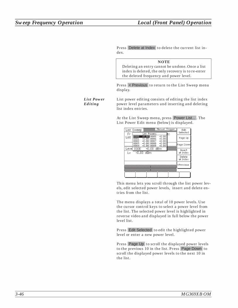
Press Delete at Index to delete the current list in-dex.
NOTEDeleting an entry cannot be undone. Once a listindex is deleted, the only recovery is to re-enterthe deleted frequency and power level.
Press < Previous to return to the List Sweep menudisplay.
List PowerEditing
List power editing consists of editing the list indexpower level parameters and inserting and deletinglist index entries.
At the List Sweep menu, press Power List... . TheList Power Edit menu (below) is displayed.
This menu lets you scroll through the list power lev-els, edit selected power levels, insert and delete en-tries from the list.
The menu displays a total of 10 power levels. Usethe cursor control keys to select a power level fromthe list. The selected power level is highlighted inreverse video and displayed in full below the powerlevel list.
Press Edit Selected to edit the highlighted powerlevel or enter a new power level.
Press Page Up to scroll the displayed power levelsto the previous 10 in the list. Press Page Down toscroll the displayed power levels to the next 10 inthe list.
3-46 MG369XB OM
Sweep Frequency Operation Local (Front Panel) Operation

Press Insert at Index to insert the default powerlevel (0 dBm) at the current list index.
NOTEBecause the list size is fixed, inserting a new in-dex will cause the last index to be lost. The fre-quency and power level at list index 1999 will bedeleted and cannot be recovered.
Press Delete at Index to delete the current list in-dex.
NOTEDelete entry cannot be undone. Once a list in-dex is deleted, the only recovery is to re-enterthe deleted frequency and power level.
Press < Previous to return to the List Sweep menudisplay.
Copying Data from the CW MenuAn easy method of entering frequency and powerlevel information into the current list index is tocopy the data from the CW menu.
First, access the main List Sweep menu and pressthe Edit List Index soft-key to open the list index pa-rameter. Then, select the list index that you wantthe data to be added to.
Next, press the CW soft-key at the bottom of thedisplay. The CW menu (below) is displayed.
Use the Edit F1 and Edit L1 soft-keys to set thefrequency and power level to the values you wish toenter into the current list index.
Press the Copy to List soft-key to copy the data tothe current list index.
MG369XB OM 3-47
Local (Front Panel) Operation Sweep Frequency Operation

Once the frequency and power level information hasbeen entered into the current list index, the list in-dex is incremented by one.
Selecting aList SweepRange
Selecting a sweep range involves choosing a start in-dex and a stop index for the list sweep.
To access the Sweep menu (below) from the mainList Sweep menu, press Sweep > .
This menu lets you select a list sweep range, setdwell-time-per-step, and access the trigger menu.
Press Start Index [LIB(xxxx)] to open the list sweepstart index parameter.
Press Stop Index [LIE(xxxx)] to open the list sweepstop index parameter.
Press Dwell Time [LDT] to open thedwell-time-per-step parameter.
Open the parameter you wish to change, then editthe current value using the cursor control keys, ro-tary data knob, or enter a new value using the keypad and appropriate termination soft-key. When youhave finished setting the open parameter, close it bypressing its menu soft-key or by making anothermenu selection.
To access the List Sweep Trigger menu from thismenu, press Trigger > . The trigger menu lets youselect a sweep trigger mode (described on the follow-ing page).
Press < Previous to return to the main List Sweepmenu display.
3-48 MG369XB OM
Sweep Frequency Operation Local (Front Panel) Operation

Selecting aList SweepTrigger
There are four modes of sweep triggering in listsweep frequency mode, each selectable from the trig-ger menu. The following is a description of eachmode.
� Auto (Automatic)—The output sweepsbetween the specified list start and stopindexes, dwelling at each list index for thespecified dwell time
� External—The output sweep recurs whentriggered by an external TTL-compatible clockpulse to the rear panel AUX I/O connector
� Single (Trig)—A single output sweep startswhen the trigger key is pressed. If a sweep isin progress when the key is pressed, it abortsand resets
� Manual—(list sweep default trigger mode) Thelist index is incremented or decremented byusing the front panel cursor control keys. Thelist index can also be incremented using an ex-ternal trigger input. Each trigger incrementsthe list index by one
To access the List Sweep Trigger menu (below) fromthe Sweep menu, press Trigger > .
To select a sweep trigger mode, press its menusoft-key.
� Press Auto [AUT] to select automatic trigger-ing
� Press External [HWT] to select external trig-gering
� Press Single [EXT] to select single sweep trig-gering
� Press Manual [MNT] to select manual trigger-ing
MG369XB OM 3-49
Local (Front Panel) Operation Sweep Frequency Operation

A message showing the sweep trigger mode selectedappears on the right side of frequency title bar.
If you select the single sweep trigger mode, themenu display adds the menu soft-key Trigger .Pressing Trigger [TRG] starts a single sweep. If asingle sweep is in progress, pressingTrigger [RSS] causes the sweep to abort and reset.
Press < Previous to return to the Sweep menu dis-play.
NOTEWith Auto trigger selected and the dwell-time-per-step set to a small value, display updatingslows down. This ensures that the sweep speedis not adversely affected. Because of this poten-tial display update slow down, when leavingList Sweep mode with Auto trigger selected foranother mode, Auto trigger is automaticallyturned off and Manual trigger is selected. Thus,when List Sweep mode is entered, the displayupdating will be back to normal speed.
3-50 MG369XB OM
Sweep Frequency Operation Local (Front Panel) Operation

3-9 Fixed Power LevelOperation
The MG3692B provides main band leveled output power over a maxi-mum range of up to 32 dB (up to 135 dB with Option 2) for CW andsweep frequency operations. Instruments with Option 15 provide lev-eled output power over a maximum range of up to 24 dB (up to 133 dBwith Option 2). The following paragraphs describe how to place thesignal generator in fixed (non-swept) power level mode, select a powerlevel for output, select logarithmic or linear units, and activate leveloffset. Use the Fixed (Non-Swept) Power Level Mode menu map(Chapter 4, Figure 4-7) to follow the menu sequences.
SelectingFixed PowerLevel Mode
To place the MG369XB in a fixed power level modefrom a CW or sweep frequency menu, press Level .At the resulting menu display, press Level . TheLevel menu (below) is displayed.
This menu lets you perform the following:
� Edit the power level parameter
� Set the power level to 1 dB below specifiedmaximum leveled output power (CW only)
� Edit the level offset parameter
� Turn level offset on/off
Selecting aPower Level
There are several ways to select a power level foroutput. You can edit the current power level, enter anew power level, or select one of the 10 preset powerlevel parameters.
Editing the Current Power LevelPress Edit L1 [XL1] to open the power level parame-ter, then edit the current power level using the cur-sor control keys or the rotary data knob. To close theopen power level parameter, press Edit L1 or makeanother menu selection.
MG369XB OM 3-51
Local (Front Panel) Operation Fixed Power Level Operation

Entering a New Power LevelPress Edit L1 [XL1] to open the power level parame-ter, then enter the new power level using the keypadand appropriate termination soft-key.
To close the open power level parameter, pressEdit L1 or make another menu selection.
Selecting a Preset Power LevelTo select one of the preset power levels for output,press Level Control > . The Level Control menu(below) is displayed.
This menu lets you perform the following:
� Select one of the preset power levels L0 [L0], L1[L1], L2 [L2], L3 [L3], or L4 [L4] for output
� Edit each preset power level
� Access the Level List menu (to tag, edit, or out-put a power level from the list)
� Select a tagged power level from the Level Listfor output using the Scan Up or Scan Downkeys
� Select Logarithmic or Linear units
Press Units> [LOG/LIN] to display the Units menu(left) and to select the power level units. When Logis selected, units are dBm or dB�V; when Linear isselected, units are mV. The units are displayed withthe indicated power level to reflect your selection.
Press < Previous to return to the Level menu dis-play.
3-52 MG369XB OM
Fixed Power Level Operation Local (Front Panel) Operation

Level ListTo access the Level List menu (below), press LevelList... . This menu lets you select a power level fromthe list to tag, edit, or output.
Use the cursor control keys to select a power levelfrom the level list. The selected power level is high-lighted in reverse video and displayed in full belowthe level list.
Press Tag Selected to tag the selected power level(place an L in front of it). If a power level is alreadytagged, pressing Tag Selected will un-tag the se-lected power level (remove the L). Tagging selectedpower levels lets you quickly switch between themusing the scan soft-keys of the Level Control menu.
Press Edit Selected to edit the selected power levelor enter a new power level.
Press Output Level to output the selected level. Onthe level list, the output power level selection ismarked by a black square or, if tagged, an L high-lighted in reverse video. This power level is outputuntil you select another level from the list and pressOutput Level .
When you are finished , press < Previous to returnto the Level Control menu display.
MG369XB OM 3-53
Local (Front Panel) Operation Fixed Power Level Operation

Level Offset Level offset lets you compensate for a device on thesignal generator's output that alters the RF outputpower level at the point of interest. For example, thepower level at the test device may be less or morethan the displayed power level because of the lossthrough an external transmission line or the gain ofan amplifier located between the MG369XB RF out-put and the test device. Using the level offset func-tion, you can apply a constant to the displayedpower level that compensates for this loss or gain.The displayed power level will then reflect the ac-tual power level at the test device.
To enter an offset value and apply it to the displayedpower level, access the Level menu. Then pressEdit Offset [LOS]. This opens the offset parameter
for editing (below).
Edit the current offset value using the cursor con-trol keys, rotary data knob, or enter a new offsetvalue using the keypad and appropriate terminationsoft-key. To close the open offset parameter whenyou are done, press Edit Offset or make anothermenu selection.
3-54 MG369XB OM
Fixed Power Level Operation Local (Front Panel) Operation

Press Offset [LO1] to apply the offset to the dis-played power level. In this example, a+2.00 dB offsetis applied to L1. L1 then displays a power level of+2.00 dBm.
When Offset is selected ON, the message OFFSETis displayed on all menu displays to remind you thata constant offset has been applied to the displayedpower level.
Press Offset [LO0] again to remove the offset fromthe displayed power level.
MG369XB OM 3-55
Local (Front Panel) Operation Fixed Power Level Operation

3-10 Power Level SweepOperation
The signal generator provides leveled output power sweeps at CW fre-quencies and in conjunction with frequency sweeps. Power levelsweeps can be from a high level to a low level or vice versa. Powerlevel sweeps can be selected to be linear or logarithmic. The followingparagraphs provide descriptions and operating instructions for theCW power sweep mode and the sweep frequency/step power modes.Use the CW Power Sweep Mode and Sweep Frequency/Step PowerMode menu maps (Chapter 4, Figures 4-8 and 4-9) to follow the menusequences.
Selecting CWPower SweepMode
In the CW power sweep mode, output power stepsbetween any two power levels at a single CW fre-quency. Available menus let you set or select thesweep range, the step size, the dwell time-per-step,and the type of power sweep (linear or logarithmic)and sweep trigger.
To place the MG369XB in a CW power sweep modefrom a CW frequency menu, press Level . At the re-sulting menu display, press Level Sweep . The CWLevel Sweep menu (below) is displayed.
This menu lets you perform the following:
� Select a power level sweep range (edit thesweep start and stop power level parameters)
� Set the dwell time-per-step
� Set the step size
� Set the number of steps
� Access the trigger menu (select a sweep trig-ger)
3-56 MG369XB OM
Power Level Sweep Operation Local (Front Panel) Operation
Performing power level sweeps that cross step attenuatorswitch points can cause excessive wear on the switches andreduce the life expectancy of the step attenuator.
CAUTION

Setting CWPower SweepStep Size andDwell Time
There are two ways to set the size of each step of theCW power sweep—set the step size or set the num-ber of steps. The step size range is 0.01 dB (Log) or0.001 mV (Linear) to the full power range of the sig-nal generator; the number of steps range is 1 to10,000. The dwell time-per-step of the CW powersweep can be set for any time in the range of 1 ms to99 sec. If the sweep crosses a step attenuator set-ting, there will be a sweep dwell of approximately20 ms to allow setting of the step attenuator.
Press Dwell Time [PDT] to open the dwell time-per-step parameter.
Press Step Size to open the step size parameter.
Press Num of Steps [PNS] to open the number ofsteps parameter.
Open the parameter you wish to change, then editthe current value using the cursor control keys, ro-tary data knob, or enter a new value using the keypad and appropriate termination soft-key. When youhave finished setting the open parameter, close it bypressing its menu soft-key or by making anothermenu selection.
To access the CW Level Sweep Trigger menu fromthis menu, press Trigger > .
Selecting aCW PowerSweep Trigger
There are three modes of triggering provided for theCW power sweep—automatic, external, and single.The sweep trigger is selectable from the CW LevelSweep Trigger menu. The following is a descriptionof each trigger mode.
� Auto (Automatic)–The CW power sweepcontinually sweeps from its start power level toits stop power level with optimal retrace time
� External–The CW power sweep recurs whentriggered by an external TTL-compatible clockpulse to the rear panel AUX I/O connector
� Single–A single CW power sweep starts whenthe trigger key is pressed. If a sweep is inprogress when the key is pressed, it aborts andresets
MG369XB OM 3-57
Local (Front Panel) Operation Power Level Sweep Operation
RANGE
This error message is displayedwhen (1) the step size value enteredis greater than the level sweeprange or (2) the number of steps en-tered results in a step size of lessthan 0.01 dB (Log) or 0.001 mV(Linear). Entering a valid step sizewill clear the error.

To access the CW Level Sweep Trigger menu fromthe CW Level Sweep menu, press Trigger > .
To select a CW power sweep trigger mode, press itsmenu soft-key.
� Press Auto [AUT] to select automatic trigger-ing
� Press External [HWT] to select external trig-gering
� Press Single [EXT] to select single sweep trig-gering
A message showing the CW power sweep triggermode selected appears on the right side of the levelmode title bar.
If you select the single sweep trigger mode, themenu display adds the menu soft-key Trigger .Pressing Trigger [TRG or TRS] starts a single CWpower sweep. If a single CW power sweep is in prog-ress, pressing Trigger [RSS] causes the sweep toabort and reset.
Press < Previous to return to the CW Level Sweepmenu display.
3-58 MG369XB OM
Power Level Sweep Operation Local (Front Panel) Operation

Selecting aPower LevelSweep Range
Selecting a power level sweep range consists ofchoosing a start and stop level for the power levelsweep. The power level sweep range selection pro-cess is identical for all power level sweepmodes—CW power sweep and sweep frequency/steppower. You can select a power level sweep range asfollows:
� Edit the current start and stop power level pa-rameter values
� Enter new start and stop power level parame-ter values
� Select one of the preset power level sweeprange parameters (L1-L2, L3-L4, L5-L6, L7-L8,or L9-L0)
Editing the Current Start / Stop Power LevelsTo edit the current power level sweep range, open ei-ther the start or stop power level parameter. In thedisplay above, Edit L1 [XL1] opens the start powerlevel parameter and Edit L2 [XL2] opens the stoppower level parameter.
Edit the open power level parameter using the cur-sor control keys or the rotary data knob. When youare finished, close the open parameter by pressingits menu edit soft-key or by making another menuselection.
Entering New Start / Stop Power LevelsTo enter a new power level sweep range start byopening either the start or stop power level parame-ters (press Edit L1 [XL1] or Edit L2 [XL2] ).
Enter a new power level using the keypad and ap-propriate terminator soft-key. When you are fin-ished, close the open parameter by pressing itsmenu edit soft-key or by making another menu se-lection.
MG369XB OM 3-59
Local (Front Panel) Operation Power Level Sweep Operation

Selecting a Preset Power Level Sweep RangeThere are five preset power level sweep range pa-rameters selectable in the power level sweep modes.These preset power level sweep range parametersare L1-L2, L3-L4, L5-L6, L7-L8, and L9-L0.
To select one of the preset power level sweep rangesfrom a Level Sweep menu, press the Level Control >soft-key. The Level Sweep Control menu (below) isdisplayed.
In addition to letting you select one of the presetsweep ranges for the power level sweep, this menulets you select logarithmic or linear power levelsweep and set the start and stop power level param-eters for each selected preset sweep range.
Setting a Preset Power Level Sweep RangeAt the Level Sweep Control menu, select the powerlevel sweep range (L1-L2, L3-L4, L5-L6, L7-L8, orL9-L0) that you wish to set. The menu then displaysthe current frequency parameters for the selectedpower level sweep range. Now, use the menu editsoft-keys to open the power level parameters for ed-iting.
Edit the current power level parameter values orenter new power level parameter values for thepower level sweep range. To close the open powerlevel parameter when you are finished, press itsmenu edit soft-key or make another menu selection.
Selecting Type of Power Level SweepPress Units> [LOG/LIN] to display the Units menu(left) and to select the power level units. When Logis selected, units are dBm or dB�V; when Linear isselected, units are mV. The units are displayed withthe indicated power level to reflect your selection
3-60 MG369XB OM
Power Level Sweep Operation Local (Front Panel) Operation

Selecting aSweepFrequency/StepPower Mode
In analog sweep frequency/step power mode or stepsweep frequency/step power mode, a power levelstep occurs after each frequency sweep. The powerlevel remains constant for the length of time re-quired to complete each frequency sweep. Availablemenus let you control the type of power level sweep(linear or logarithmic), the power level sweep range,and the step size.
To select an analog sweep frequency/step powermode, start with an analog sweep menu display; toselect a step sweep frequency/step power mode, startwith a step sweep menu display. Then pressLevel .
At the resulting menu display, press Level Sweep .The Level Sweep menu (below) is displayed.
This menu lets you perform the following:
� Select a power level sweep range (edit thesweep start and stop power level parameters)
� Set the step size
� Set the number of steps
� Access the Level Sweep Trigger menu
NOTETo select logarithmic or linear power levelsweep or to select a power level sweep range, re-fer to the procedures on pages 3-59 and 3-60.
MG369XB OM 3-61
Local (Front Panel) Operation Power Level Sweep Operation

Setting PowerLevel StepSize
There are two ways to set the step size of the powerlevel step that occurs after each frequencysweep—set the step size or set the number of steps.The step size range is 0.01 dB (Log) or 0.001 mV(Linear) to the full power range of the signal genera-tor; the number of steps range is 1 to 10,000. Thepower level step size is set from the Level SweepRamp menu.
Press Step Size to open the step size parameter.
Press Num of Steps [PNS] to open the number ofsteps parameter.
Open the parameter you wish to change, then editthe current value using the cursor control keys, ro-tary data knob, or enter a new value using the key-pad and appropriate termination soft-key. When youhave finished setting the open parameter, close it bypressing its menu soft-key or by making anothermenu selection.
3-62 MG369XB OM
Power Level Sweep Operation Local (Front Panel) Operation
RANGE
This error message is displayedwhen (1) the step size value enteredis greater than the level sweeprange or (2) the number of steps en-tered results in a step size of lessthan 0.01 dB (Log) or 0.001 mV(Linear). Entering a valid step sizewill clear the error.

3-11 LevelingOperations
The MG3692B provides main band leveled output power over a maxi-mum range of up to 32 dB (up to 135 dB with Option 2) for CW andsweep frequency operations. Instruments with Option 15 provide lev-eled output power over a maximum range of up to 24 dB (up to 133 dBwith Option 2). An automatic level control (ALC) system controls theamplitude and power level of the RF output. You can select the ALCmode of operation—internal, external (detector or power meter), orfixed gain (ALC off). In addition, the signal generator provides a de-couple function that allows decoupling of the step attenuator (ifequipped) from the ALC system and a user level (flatness correction)calibration function that provides compensation for path-varia-tions-with-frequency in a test setup.
The following paragraphs provide descriptions and operating instruc-tions for the leveling modes and functions. Use the Leveling Modesmenu map (Chapter 4, Figure 4-10) to follow the menu sequences.
Selecting aLeveling Mode
The ALC system is a feedback control system, inwhich the output power is measured at a detectorand compared with the expected power level. If theoutput and desired power levels do not equal, theALC adjusts the power output until they do. TheALC feedback signal can come from either the inter-nal detector or an external detector or power meter.Alternatively, the output power can be set to a fixedlevel without using the normal feedback (ALC off).The ALC mode menu lets you select a leveling mode.
To access the ALC Mode menu, first press Level .
At the Level/ALC Select menu display, pressALC Mode . The ALC Mode menu (below) is dis-
played.
MG369XB OM 3-63
Local (Front Panel) Operation Leveling Operations

The ALC Mode menu lets you perform the following:
� Access the Leveling menu (select the ALCmode of operation)
� Access the Attenuation menu (decouple the at-tenuator, if equipped, from the ALC systemand set the power level and attenuation)
To access the Leveling menu from the ALC Modemenu, press Leveling > . The Leveling menu (below)is displayed.
Internal LevelingThis is the normal (default) leveling mode. Outputpower is sensed by the MG369XB’s internal detector.The detector output signal is fed back to the ALCcircuitry to adjust the output power level. InternalALC is selected from the leveling menu.
To select internal ALC, press Internal [IL1].
Pressing one of the other leveling menu soft-keysExternal Detector [DL1], Power Meter [PL1], orFixed Gain [LV0] will turn off internal leveling.
Press < Previous to return to the ALC Mode menu.
3-64 MG369XB OM
Leveling Operations Local (Front Panel) Operation

External LevelingIn external leveling, the output power from theMG369XB is detected by an external detector orpower meter. The signal from the detector or powermeter is returned to the ALC circuitry via the rearpanel EXT ALC IN connector. The ALC adjusts theoutput power to keep the power level constant at thepoint of detection. The external ALC source input isselected from the leveling menu.
To select the external ALC input from an externaldetector, press External Detector [DL1].
To select the external ALC input from a power me-ter, press Power Meter [PL1].
After the sensor type is selected, the attenuator (ifinstalled) is decoupled and the RF Level DAC valueis displayed as shown below:
The level indicator will also show the unleveled con-dition. The RF Level DAC adjustable range is from 0to 16383.
Press < Previous to return to the ALC Mode menudisplay or press Internal to return to normal ALCoperation.
MG369XB OM 3-65
Local (Front Panel) Operation Leveling Operations

Fixed GainIn the fixed gain mode, the ALC is disabled. The RFLevel DAC and step attenuator (if installed) areused to control the relative power level. Power is notdetected at any point, and the absolute power levelis uncalibrated. Fixed gain mode is selected from theleveling menu.
To select fixed gain mode, access the Leveling menu,then press Fixed Gain [LV0]. After fixed gain modeselected, the attenuator (if installed) is decoupledand the RF Level DAC value is displayed as shownbelow:
The level indicator will also show the unleveled con-dition. The RF Level DAC adjustable range is from 0to 16383.
Press < Previous to return to the ALC Mode menudisplay or press Internal to return to normal ALCoperation.
Auto Fixed GainIn auto fixed gain mode, the ALC is enabled for theinitial power sweep, frequency sweep, or CWfrequency setting to obtain a sample of the RF LevelDAC voltages. After the DAC voltages are sampled,the ALC is disabled and the sampled RF Level DACvoltages are applied for all subsequent operation. Ifa frequency or level parameter is changed, the ALCwill again sample the RF Level DAC voltages andapply them to the new settings.
To select auto fixed gain mode, access the Levelingmenu, then press Auto Fixed Gain [LV1].
Press < Previous to return to the ALC Mode menudisplay or press Internal to return to normal ALCoperation.
3-66 MG369XB OM
Leveling Operations Local (Front Panel) Operation
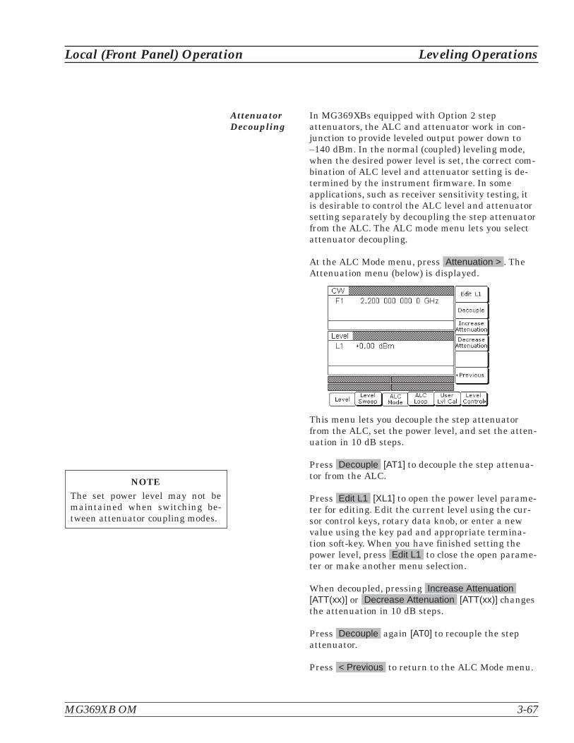
AttenuatorDecoupling
In MG369XBs equipped with Option 2 stepattenuators, the ALC and attenuator work in con-junction to provide leveled output power down to–140 dBm. In the normal (coupled) leveling mode,when the desired power level is set, the correct com-bination of ALC level and attenuator setting is de-termined by the instrument firmware. In someapplications, such as receiver sensitivity testing, itis desirable to control the ALC level and attenuatorsetting separately by decoupling the step attenuatorfrom the ALC. The ALC mode menu lets you selectattenuator decoupling.
At the ALC Mode menu, press Attenuation > . TheAttenuation menu (below) is displayed.
This menu lets you decouple the step attenuatorfrom the ALC, set the power level, and set the atten-uation in 10 dB steps.
Press Decouple [AT1] to decouple the step attenua-tor from the ALC.
Press Edit L1 [XL1] to open the power level parame-ter for editing. Edit the current level using the cur-sor control keys, rotary data knob, or enter a newvalue using the key pad and appropriate termina-tion soft-key. When you have finished setting thepower level, press Edit L1 to close the open parame-ter or make another menu selection.
When decoupled, pressing Increase Attenuation[ATT(xx)] or Decrease Attenuation [ATT(xx)] changesthe attenuation in 10 dB steps.
Press Decouple again [AT0] to recouple the stepattenuator.
Press < Previous to return to the ALC Mode menu.
MG369XB OM 3-67
Local (Front Panel) Operation Leveling Operations
NOTEThe set power level may not bemaintained when switching be-tween attenuator coupling modes.

ALC PowerSlope
The ALC power slope function lets you compensatefor system, cable, and waveguide variations due tochanges in frequency. This is accomplished by lin-early increasing or decreasing power output as thefrequency increases. As shown in the following illus-tration, the power slope function provides you withthe ability to set both the power slope and the pivotpoint. The ALC loop menu lets you activate the ALCpower slope function.
To access the ALC Loop menu from the Level ALCControl menu display, press ALC Loop . The ALCLoop menu (below) is displayed.
3-68 MG369XB OM
Leveling Operations Local (Front Panel) Operation
PowerSlope
Power at DUTWith Compensation
Power at DUTWithout Compensation
Power SlopePivot Point
Frequency
Po
wer
Lev
el

Press Slope On/Off [SL1] to activate the ALC powerslope function.
Press Edit Pivot [PVT] to open the pivot point fre-quency parameter for editing. Edit the current fre-quency using the cursor control keys, rotary dataknob, or enter a new value using the keypad and ap-propriate termination key. When you have finishedsetting the open parameter, close it by pressingEdit Pivot or by making another menu selection.
Press Edit Slope [SLP] to open the slope parameterfor editing. Edit the current slope value using thecursor control keys, rotary data knob, or enter a newvalue using the key pad. When you have finishedsetting the open parameter, close it by pressingEdit Slope or by making another menu selection.
While monitoring the power level at the device-un-der-test (DUT), adjust the power slope and pivotpoint to level the power at the DUT.
Press Slope On/Off [SL0] again to deactivate theALC power slope function.
MG369XB OM 3-69
Local (Front Panel) Operation Leveling Operations
SLOPE
When Power Slope is selected ON,this status message is displayed onall menu displays to remind youthat a power slope correction hasbeen applied to the ALC.

User Cal(User PowerLevel FlatnessCalibration)
The User Cal (user power level flatness calibration)function lets you compensate for path variationswith frequency that are caused by external switch-ing, amplifiers, couplers, mixers, multipliers, divid-ers, and cables in the test setup. This is done bymeans of an entered power-offset table from a GPIBpower meter or calculated data. When user levelflatness calibration is activated, the set power levelis delivered at the point in the test setup where thecalibration was performed. This “flattening” of thetest point power level is accomplished by summing apower-offset word (from the power-offset table) withthe signal generator's normal power level DAC wordat each frequency point.
Up to five user level flatness calibration power-off-set tables from 2 to 801 frequency points-per-tablecan be created and stored in the MG369XB memoryfor recall. The GPIB power meters supported are theAnritsu Models ML2437A, ML2438A, and ML4803Aand the Hewlett-Packard Models 437B, 438A, and70100A. The MG369XB’s internal power meter, pro-vided with Option 8, may also be used. Refer to Sec-tion 3-17 on page 3-116 for information on using theinternal power meter.
3-70 MG369XB OM
Leveling Operations Local (Front Panel) Operation
! / � � � 0 � � � � � 1 2' & � � � � � � 2
� � � � � � � 2 � � � � �
� � � � �� � � � �
� � � � � � � �
� ( � � �3 � � � �# � � � % � / � �
! � � � � �
� � � * � � �
� � � � � � �� � � � � � � � �� � � � �
� � � � � � � � � � � � � � � � � � � �
� % * $
� % * $
Figure 3-4. Setup for Creating a Power-Offset Table (User Level Flatness Calibration)

Equipment SetupTo create a power-offset table for user level flatnesscalibration, connect the equipment (shown inFigure 3-4) as follows:
Step 1. Using a GPIB cable, connect the powermeter to the MG369XB.
Step 2. Calibrate the power meter the powersensor.
Step 3. Connect the power sensor to the point inthe test setup where the corrected powerlevel is desired.
Power Meter Model and GPIB AddressIn order for the MG369XB to control the power me-ter, the GPIB address and power meter model mustbe selected from the Configure GPIB menu.
Press System to access the System menu display.At the System menu display, press Config . The Sys-tem Configuration menu (below) is displayed.
Next, press GPIB > . The Configure GPIB menu(below) is displayed.
MG369XB OM 3-71
Local (Front Panel) Operation Leveling Operations

At the Configure GPIB menu, press More > to ac-cess the Additional Configure GPIB menu (below).
Press Power Mtr Address to change the address ofthe power meter on the GPIB (the power meter's de-fault address is 13). Enter the new address, between1 and 30, using the cursor control keys or the dataentry key pad. The new GPIB address will appearon the display.
Press Power Mtr Select to select one of the followingpower meters:
� Anritsu ML2430A or ML4803
� Internal (Option 8)
� Hewlett-Packard 437, 438, or 70100A
Press < Previous to return to the main ConfigureGPIB menu display.
At the Configure GPIB menu, press < Previous toreturn to the System Configuration menu display.
Creating a Power-Offset TableThe MG369XB must be in CW frequency mode andfixed (non-swept) power level mode in order to cre-ate a power-offset table for user level flatness cor-rection.
Place the signal generator in CW frequency mode bypressing Frequency . At the resulting menu display,press CW . The MG369XB is now in CW frequencymode.
Place the signal generator in a fixed power levelmode by pressing Level . At the resulting menu dis-play, press Level . The MG369XB is now in fixed(non-swept) power level mode.
3-72 MG369XB OM
Leveling Operations Local (Front Panel) Operation
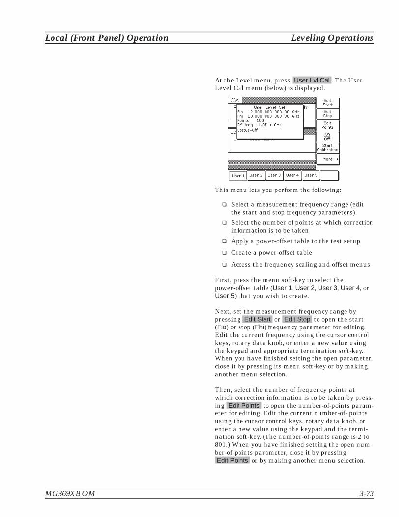
At the Level menu, press User Lvl Cal . The UserLevel Cal menu (below) is displayed.
This menu lets you perform the following:
� Select a measurement frequency range (editthe start and stop frequency parameters)
� Select the number of points at which correctioninformation is to be taken
� Apply a power-offset table to the test setup
� Create a power-offset table
� Access the frequency scaling and offset menus
First, press the menu soft-key to select thepower-offset table (User 1, User 2, User 3, User 4, orUser 5) that you wish to create.
Next, set the measurement frequency range bypressing Edit Start or Edit Stop to open the start(Flo) or stop (Fhi) frequency parameter for editing.Edit the current frequency using the cursor controlkeys, rotary data knob, or enter a new value usingthe keypad and appropriate termination soft-key.When you have finished setting the open parameter,close it by pressing its menu soft-key or by makinganother menu selection.
Then, select the number of frequency points atwhich correction information is to be taken by press-ing Edit Points to open the number-of-points param-eter for editing. Edit the current number-of- pointsusing the cursor control keys, rotary data knob, orenter a new value using the keypad and the termi-nation soft-key. (The number-of-points range is 2 to801.) When you have finished setting the open num-ber-of-points parameter, close it by pressingEdit Points or by making another menu selection.
MG369XB OM 3-73
Local (Front Panel) Operation Leveling Operations

If any frequency scaling or offset appears at the lev-eling point, press More > to access the power meterfrequency scaling and offset menu below.
Then press PM Freq Scale or PM Freq Offset andedit the frequency scaling or offset value using thecursor, keypad, or rotary knob. The scaling factorrange is - 10 to + 10 and the offset frequency rangeis -150 to +150 GHz. Press < Previous to return tothe user level cal menu.
Now, press Start Calibration to begin automaticallytaking power level correction information at eachfrequency point. During this process the menu dis-plays the status: Calibrating along with the currentmeasurement frequency point.
NOTETo terminate the measurement process at anytime before completion, press Abort .
Once the power-offset table has been created, it isstored in non-volatile memory. The power-offset ta-ble is now ready to be applied to the test setup. Dis-connect the powers sensor and power meter fromthe test setup.
Applying User Level Flatness CorrectionWhenever user level flatness correction is applied tothe test setup by activating the power-offset table,the set power level is delivered at the point wherethe calibration was performed.
To activate the selected power-offset table and applyuser level flatness correction to the test setup, pressOn/Off [LU1...5]. The User Level Cal menu will dis-
play: Status—On.
3-74 MG369XB OM
Leveling Operations Local (Front Panel) Operation

When a power-offset table is selected ON, the mes-sage USER 1...5 is displayed on all menu displaysto remind you that a user level flatness correctionhas been applied to the ALC.
To turn off the selected power-offset table and re-move user level flatness correction from the testsetup, press On/Off [LU0] again. The User LevelCal menu will display: Status—Off.
Entering a Power-Offset Table via GPIBUser level flatness correction can be applied to thetest setup using a power-offset table created fromcalculated data and entered via the GPIB. Refer tothe MG369XB GPIB Programming Manual(P/N: 10370-10366) for information and instructionson creating a power-offset table and entering it viathe GPIB.
Erasing the Power-Offset Tables from MemoryThe power-offset tables are stored in non-volatilememory. A master reset is required to erase the con-tents of the tables and reprogram them with defaultdata.
To perform a master reset, proceed as follows:
Step 1. With the MG369XB in standby, press andhold the RF OUTPUT ON/OFF key.
Step 2. Press the LINE OPERATE/STANDBY keyto turn the instrument on.
Step 3. When the first menu is displayed (afterthe start-up display), release the RF OUT-PUT ON/OFF key.
For instruments without a front panel, a master re-set can be performed at power on by groundingpin 21 of the rear panel AUX I/O connector.
The contents of non-volatile memory have now beenerased and reprogrammed with default data.
MG369XB OM 3-75
Local (Front Panel) Operation Leveling Operations
NOTEThe master reset functionoverwrites all information stored inthe non-volatile memory with de-fault values. This includes the ninestored front panel setups and thetable of 2000 frequency/power levelsets used for list sweep mode.

3-12 SystemConfiguration
The system configuration function provides menus that let you set orselect instrument configuration items; for example, display contrast,polarity of blanking and video marker outputs, RF on or off during re-trace or between steps, frequency scaling, GPIB operating parameters,external interface language, and increment sizes for frequency, powerlevel, and time parameters. Use the System Configuration menu map(Chapter 4, Figure 4-15) to follow the menu sequences.
Accessing theSystemConfigurationMenu
To access the System Configuration menu, firstpress System . At the System menu display, pressConfig . The System Configuration menu (below) isdisplayed.
This menu lets you access the following:
� Front Panel Configuration Menu
� Rear Panel Configuration Menu
� RF Configuration Menu
� GPIB Configuration Menu
� Increment Configuration Menu
3-76 MG369XB OM
System Configuration Local (Front Panel) Operation
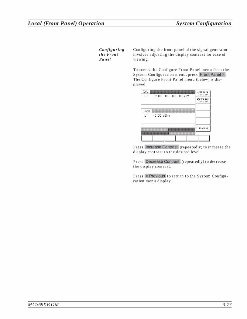
Configuringthe FrontPanel
Configuring the front panel of the signal generatorinvolves adjusting the display contrast for ease ofviewing.
To access the Configure Front Panel menu from theSystem Configuration menu, press Front Panel > .The Configure Front Panel menu (below) is dis-played.
Press Increase Contrast (repeatedly) to increase thedisplay contrast to the desired level.
Press Decrease Contrast (repeatedly) to decreasethe display contrast.
Press < Previous to return to the System Configu-ration menu display.
MG369XB OM 3-77
Local (Front Panel) Operation System Configuration

Configuringthe RearPanel
Configuring the rear panel of the signal generatorconsists of selecting the polarity of the retraceblanking, band switch blanking, retrace penlift, andvideo marker outputs.
To access the Configure Rear Panel menu from theSystem Configuration menu, press Rear Panel > .The Configure Rear Panel menu (below) is dis-played.
Press Blanking +/– [BPP/BPN] to select a +5V or–5V level for the retrace and band switch blankingoutputs. The retrace and band switch blanking sig-nal outputs are both available at the rear panelAUX I/O connector (retrace blanking at pin 6; bandswitch blanking at pin 20). The display will reflectyour selection.
Press Marker +/– to select a +5V or –5V level forthe video marker output when video markers are se-lected ON. The video marker signal output is avail-able at the rear panel AUX I/O connector pin 5. Thedisplay will reflect your selection.
Press Penlift to select Normally Open (N/O) [PPO]or Normally-Closed (N/C) [PPC] contacts on the in-ternal penlift relay. The penlift relay output, avail-able at pin 12 of the rear panel AUX I/O connector, isused to lift a plotter pen at band switch points, atfilter switch points, and during sweep retrace. Thedisplay will reflect your selection.
Press < Previous to return to the System Configu-ration menu display.
3-78 MG369XB OM
System Configuration Local (Front Panel) Operation

Configuringthe RF
Configuring the RF of the MG369XB involves thefollowing:
� Selecting RF on or off during retrace
� Selecting RF on or off during frequencyswitching in CW, step sweep, and list sweepmodes
� Selecting whether a sweep triggered by a sin-gle or external trigger should rest at the top orbottom of the sweep ramp
� Selecting RF on or off at reset
� Setting the reference multiplier value for fre-quency scaling
� Selecting 40 dB or 0 dB of attenuation whenRF is switched off (units with a step attenu-ator, Option 2, installed)
To access the Configure RF menu (below) from theSystem Configuration menu, press RF > .
Press Retrace RF to select RF on [RT1] or off [RT0]during retrace. The display will reflect your selec-tion.
Press Delta-F RF to select RF on [RC1] or off [RC0]during frequency switching in CW, step sweep, andlist sweep modes. The display will reflect your selec-tion.
Press Ramp Rest to select 0 or 10 for the ramp restpoint for sweeps that are triggered by a single trig-ger or external trigger. 0 indicates that the sweepwill rest at the bottom of the sweep ramp; 10 indi-cates that the sweep will rest at the top of the sweepramp. The display will reflect your selection.
Press Reset State to select RF on [RO0] or off [RO1]at reset. The display will reflect your selection.
MG369XB OM 3-79
Local (Front Panel) Operation System Configuration

Press More > to access the additional Configure RFmenu for more selections.
Additional Configure RF MenuWhen you press More > , the Additional ConfigureRF menu (below) is displayed.
Frequency ScalingLets you set a reference multiplier value and applyit to all frequency parameters. The reference multi-plier can be any value between 0.1 and 18.Changing the multiplier value changes the enteredand displayed frequencies, but does not affect theoutput of the signal generator. For example:
Frequency scaling set to 4CW frequency set to 20 GHzMG369XB output is 5 GHz (20 GHz 4)
Press Frequency Scaling [FRS] to open the refer-ence multiplier parameter, then edit the currentvalue using the cursor control keys, rotary dataknob, or enter a new value using the data entry keypad and the terminator soft-key. To close the openmultiplier parameter, press Frequency Scaling ormake another menu selection.
Press Terminate RF Off [TR1] to select 40 dB (mini-mum) of attenuation when RF is switched off inunits with a step attenuator (Option 2) installed.This provides a better output source match. The dis-play will reflect Yes to indicate the 40 dB of attenua-tion is applied. Press Terminate RF Off [TR0] againto select 0 dB of attenuation when RF is switchedoff. The display will reflect No to indicate 0 dB of at-tenuation is applied.
Press < Previous to return to the main ConfigureRF menu display.
3-80 MG369XB OM
System Configuration Local (Front Panel) Operation
NOTEResetting the MG369XB sets thefrequency scaling reference multi-plier value to 1.
NOTEThe Terminate RF Off selection isonly available in units withOption 2 (Step Attenuator).

Configuringthe GPIB
The GPIB configuration menus let you perform thefollowing:
� Set the GPIB address and select the GPIB lineterminator for the signal generator
� Select the model and set the GPIB address forthe power meter that is used to create a userlevel flatness correction power-offset table
� Select scalar mode of operation with a WiltronModel 562 or Anritsu Model 56100A ScalarNetwork Analyzer
� Select scalar mode of operation with aGiga-tronics Model 8003, a Hewlett PackardModel 8757D or a Hewlett Packard Model8757E Scalar Network Analyzer (Only avail-able in units with the Pulse Modulation optioninstalled)
To access the Configure GPIB menu from the Sys-tem Configuration menu, press GPIB > . The Con-figure GPIB menu (below) is displayed.
Press GPIB Address [ADD] to change the address ofthe MG369XB on the bus (the CW default GPIB ad-dress is five). Enter a new address, between one and30, using the cursor control keys or the data entrykeypad and the terminator key. The new GPIB ad-dress will appear on the display.
Press GPIB Terminator to select a carriage return(CR) or a carriage return and line feed (CR/LF) asthe GPIB data delimiter. Consult the GPIB control-ler's manual to determine which data delimiter isrequired.
Press More > to access the First Additional Config-ure GPIB menu for more selections.
MG369XB OM 3-81
Local (Front Panel) Operation System Configuration

First Additional Configure GPIB MenuWhen you press More >, the First Additional Config-ure GPIB menu (below) is displayed.
This menu lets you select the model and set theGPIB address for the power meter that is used tocreate a user level flatness correction power-offsettable. (Refer to page 3-70 for a description of thisfunction.
Press Power Meter Address to change the address ofthe power meter on the GPIB (the power meter's de-fault GPIB address is 13). Enter a new address, be-tween 1 and 30, using the cursor control keys or thedata entry keypad and the terminator soft-key. Thenew GPIB address will appear on the display.
Press Power Meter Select to select the power metermodel being used. (Supported power meters are theAnritsu ML2437A, ML2438A, and ML4803A andHewlett-Packard 437B, 438A, and 70100A.)
Press 68/69 ID to enable operations with a WiltronModel 562 or Anritsu Model 56100A Scalar NetworkAnalyzer. (Refer to page 7-4 for master-slave proce-dures.) Press 68/69 ID again to disable the opera-tion.
Press Emulation > to access the Second AdditionalConfigure GPIB menu for more scalar mode of oper-ation choices (described on the following page).
Press Display Updates to have the display updatedwith the current instrument settings when in theremote operation mode.
Press < Previous to return to the main ConfigureGPIB menu display.
3-82 MG369XB OM
System Configuration Local (Front Panel) Operation
NOTEThe Emulation > selection only ap-pears on this menu display in unitswith the Pulse Modulation optioninstalled.

Second Additional Configure GPIB MenuWhen you press Emulation > the Second AdditionalGPIB menu (below) is displayed.
Press 8003 Scalar to enable operations with aGiga-tronics Model 8003 Scalar Network Analyzer.Press 8003 Scalar again to disable the operation.
Press 8757D Scalar to enable operations with aHewlett Packard Model 8757D Scalar Network Ana-lyzer. Press 8757D Scalar again to disable the oper-ation.
Press 8757E Scalar to enable operations with aHewlett Packard Model 8757D Scalar Network Ana-lyzer. Press 8757E Scalar again to disable the opera-tion.
Press < Previous to return to the First AdditionalConfigure GPIB menu display.
MG369XB OM 3-83
Local (Front Panel) Operation System Configuration
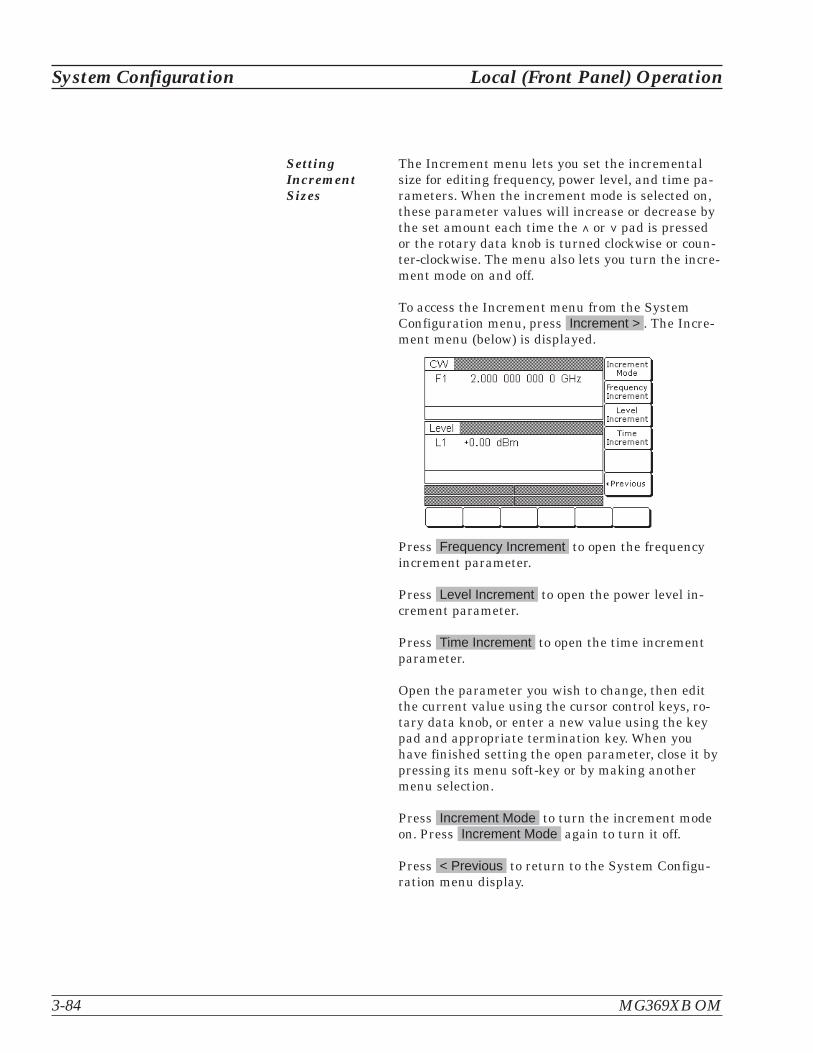
SettingIncrementSizes
The Increment menu lets you set the incrementalsize for editing frequency, power level, and time pa-rameters. When the increment mode is selected on,these parameter values will increase or decrease bythe set amount each time the � or pad is pressedor the rotary data knob is turned clockwise or coun-ter-clockwise. The menu also lets you turn the incre-ment mode on and off.
To access the Increment menu from the SystemConfiguration menu, press Increment > . The Incre-ment menu (below) is displayed.
Press Frequency Increment to open the frequencyincrement parameter.
Press Level Increment to open the power level in-crement parameter.
Press Time Increment to open the time incrementparameter.
Open the parameter you wish to change, then editthe current value using the cursor control keys, ro-tary data knob, or enter a new value using the keypad and appropriate termination key. When youhave finished setting the open parameter, close it bypressing its menu soft-key or by making anothermenu selection.
Press Increment Mode to turn the increment modeon. Press Increment Mode again to turn it off.
Press < Previous to return to the System Configu-ration menu display.
3-84 MG369XB OM
System Configuration Local (Front Panel) Operation

3-13 Saving/RecallingInstrument Setups
The MG369XB offers the capability to store up to ten complete frontpanel setups. The setups are numbered zero through nine. The follow-ing paragraphs describe how to save and recall front panel setups.
Saving Setups Once you have decided that an instrument setupshould be retained for future use, follow the proce-dure below to save the current setup:
Step 1. Press System to display the Systemmenu.
Step 2. Press Setups . The Setups menu (below)is displayed.
Step 3. Press Save [SSN(M1-9)], then enter thedesired setup number (between zero andnine) on the keypad. The setup is nowsaved.
NOTESThe current front panel settings are automati-cally saved to setup number zero when the in-strument is shutdown using the front panelLINE key. Therefore, it is recommended that youonly use setup numbers one through nine tosave front panel setups.
When an MG369XB shutdown occurs becauseof main power interruptions, the current frontpanel settings are not saved.
MG369XB OM 3-85
Local (Front Panel) Operation Saving/Recalling Instrument Setups

RecallingSetups
To recall a previously saved setup, first access theSetups menu as described below:
Step 1. Press System to display the Systemmenu.
Step 2. Press Setups to display the Setupsmenu.
Step 3. At the Setups menu, press Recall[RSN(M1-9)], then enter the setup numberon the keypad.
The MG369XB resets itself to the recalled configura-tion.
ErasingStored Setups
The front panel setups are stored in non-volatilememory. A master reset is required to erase the con-tents of the setups and reprogram them with defaultdata.
To perform a master reset, proceed as follows:
Step 1. With the MG369XB in standby mode,press and hold the RF OUTPUT ON/OFFkey.
Step 2. Press the LINE OPERATE/STANDBY keyto turn the instrument on.
Step 3. When the first menu is displayed (afterthe start-up display), release the RF OUT-PUT ON/OFF key.
The contents of non-volatile memory have now beenerased and reprogrammed with factory default data.
A master reset can also be performed by sending theGPIB command “MR” over the GPIB bus.
3-86 MG369XB OM
Saving/Recalling Instrument Setups Local (Front Panel) Operation
NOTEThe master reset function over-writes all information stored in thenon-volatile memory with defaultvalues. This includes the table of2000 frequency/power level setsused for the list sweep mode andthe five power-offset tables used forthe user level flatness correctionfunction.
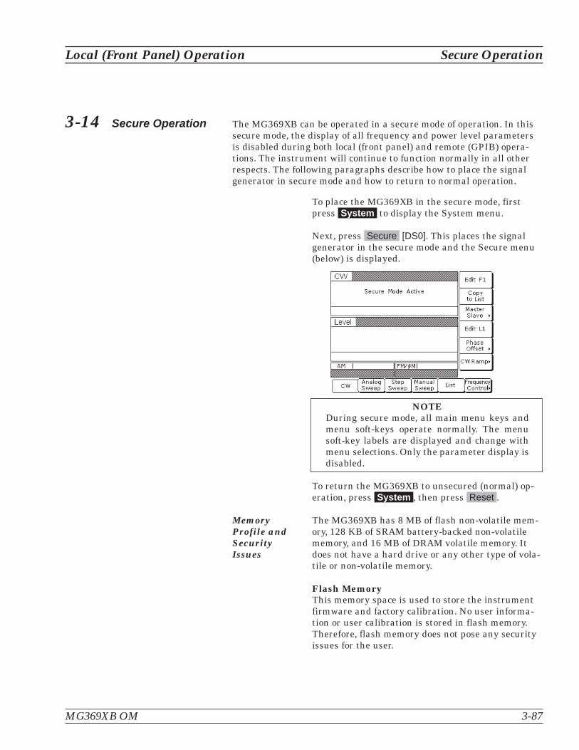
3-14 Secure Operation The MG369XB can be operated in a secure mode of operation. In thissecure mode, the display of all frequency and power level parametersis disabled during both local (front panel) and remote (GPIB) opera-tions. The instrument will continue to function normally in all otherrespects. The following paragraphs describe how to place the signalgenerator in secure mode and how to return to normal operation.
To place the MG369XB in the secure mode, firstpress System to display the System menu.
Next, press Secure [DS0]. This places the signalgenerator in the secure mode and the Secure menu(below) is displayed.
NOTEDuring secure mode, all main menu keys andmenu soft-keys operate normally. The menusoft-key labels are displayed and change withmenu selections. Only the parameter display isdisabled.
To return the MG369XB to unsecured (normal) op-eration, press System , then press Reset .
MemoryProfile andSecurityIssues
The MG369XB has 8 MB of flash non-volatile mem-ory, 128 KB of SRAM battery-backed non-volatilememory, and 16 MB of DRAM volatile memory. Itdoes not have a hard drive or any other type of vola-tile or non-volatile memory.
Flash MemoryThis memory space is used to store the instrumentfirmware and factory calibration. No user informa-tion or user calibration is stored in flash memory.Therefore, flash memory does not pose any securityissues for the user.
MG369XB OM 3-87
Local (Front Panel) Operation Secure Operation

SRAM Battery-backed MemoryThis memory space is used to store user setups anduser calibrations. This memory may contain projectsensitive or secure information.
NOTEWhen the MG369XB is removed from a secureenvironment a master reset should be executedto completely clear this memory and replacefactory default data. Master reset instructionsfor the MG369XB are given on page 3-86.
3-15 Reference LoopAdjustments
The signal source reference loop can be calibrated to an external refer-ence source and the loop bandwidth can be adjusted to accommodatevarious needs for an external reference input.
ReferenceOscillatorCalibration
The reference oscillator calibration function lets youcalibrate the internal 100 MHz crystal reference os-cillator of the MG369XB using an external 10 MHz,0 to +10 dBm reference signal.
NOTEBefore beginning calibration, always let theMG369XB warm up for a minimum of 120hours.
To perform a calibration of the internal reference os-cillator, first connect the external 10 MHz referencesignal to the MG369XB rear panel 10 MHz REF INconnector.
Next, press the System main menu key. At theSystem menu display, press Cal > to access the Cal-ibration menu (below).
Press Reference Calibration to begin calibration.
Press < Previous to return to the System menu dis-play.
3-88 MG369XB OM
Reference Loop Adjustments Local (Front Panel) Operation

When Reference Calibration is pressed, the Calibra-tion Status menu is displayed (below).
Press Proceed to start the calibration.
Press Abort to cancel the calibration and return tothe Calibration menu display.
When Proceed is pressed, the date parameteropens for data entry (below).
Using the key pad, enter the current date (in anydesired format). Then, press any terminator soft-key. The Calibration Status menu display changes toindicate calibration is in progress.
MG369XB OM 3-89
Local (Front Panel) Operation Reference Loop Adjustments

When the reference calibration is complete, the Cali-bration menu is displayed.
External Reference Not ConnectedIf a calibration is attempted without an external10 MHz reference signal connected to the rear panel10 MHz REF IN connector, the instrument will beepand the Calibration Status menu displays the fol-lowing message:
No External Reference is connected!!!
ReferenceLoopBandwidth
The MG369XB provides a user selectable externalreference loop bandwidth. Bandwidths of 10 Hz,30 Hz, 100 Hz, or 300 Hz can be selected from thefront panel system configuration menu. Selecting anarrower bandwidth provides greater immunityfrom reference related phase noise; however, refer-ence tracking will not be optimal. Selecting a widerbandwidth increases phase tracking of the externalreference; however, it also increases the susceptibil-ity to reference noise.
To select an external reference loop bandwidth, firstconnect the external 10 MHz reference signal to theMG369XB rear panel 10 MHz REF IN connector.
3-90 MG369XB OM
Reference Loop Adjustments Local (Front Panel) Operation
No External Reference is Connected!!!

Next, press the System main menu key. At theSystem menu display, press Config | Rear Panel >to access the rear panel Configuration menu (be-low).
Press the External Ref BW > soft key to access thebandwidth selections (below).
After selecting the external reference loop band-width, the setting is shown in the Configure RearPanel menu.
Press < Previous | < Previous to return to the Sys-tem menu display.
NOTEMG369XB phase noise specifications applyonly when an external reference is not con-nected.
MG369XB OM 3-91
Local (Front Panel) Operation Reference Loop Adjustments
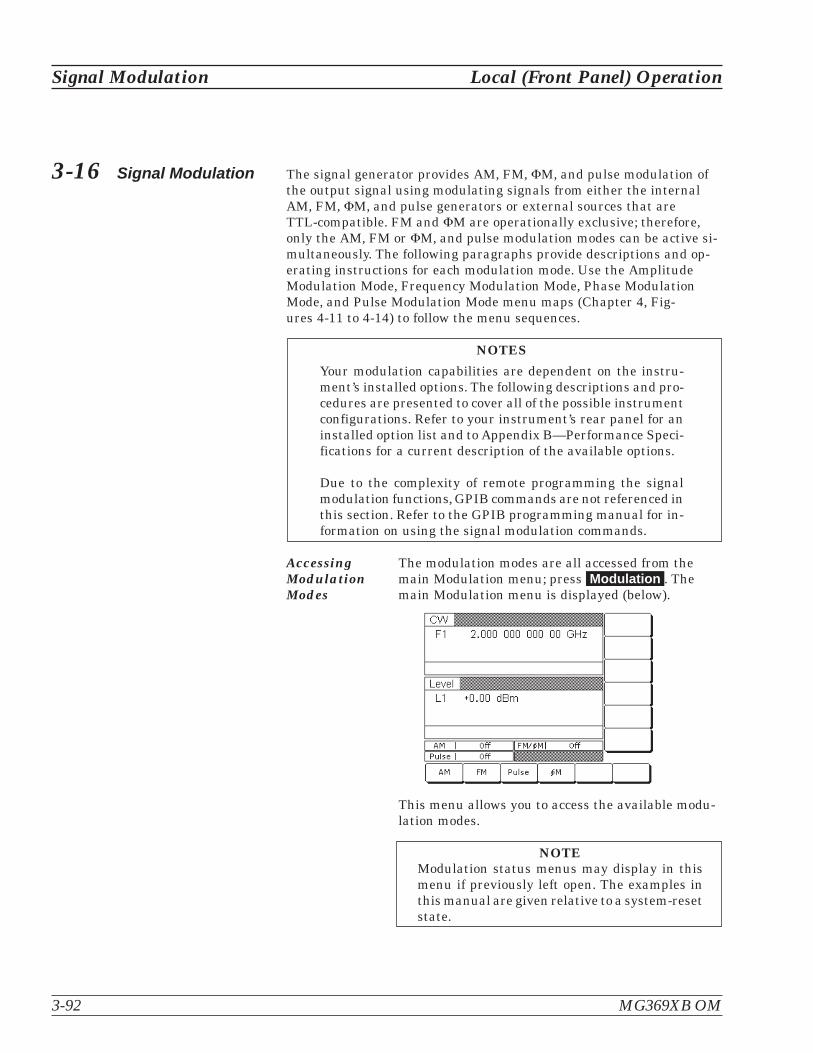
3-16 Signal Modulation The signal generator provides AM, FM, �M, and pulse modulation ofthe output signal using modulating signals from either the internalAM, FM, �M, and pulse generators or external sources that areTTL-compatible. FM and �M are operationally exclusive; therefore,only the AM, FM or �M, and pulse modulation modes can be active si-multaneously. The following paragraphs provide descriptions and op-erating instructions for each modulation mode. Use the AmplitudeModulation Mode, Frequency Modulation Mode, Phase ModulationMode, and Pulse Modulation Mode menu maps (Chapter 4, Fig-ures 4-11 to 4-14) to follow the menu sequences.
NOTES
Your modulation capabilities are dependent on the instru-ment’s installed options. The following descriptions and pro-cedures are presented to cover all of the possible instrumentconfigurations. Refer to your instrument’s rear panel for aninstalled option list and to Appendix B—Performance Speci-fications for a current description of the available options.
Due to the complexity of remote programming the signalmodulation functions, GPIB commands are not referenced inthis section. Refer to the GPIB programming manual for in-formation on using the signal modulation commands.
AccessingModulationModes
The modulation modes are all accessed from themain Modulation menu; press Modulation . Themain Modulation menu is displayed (below).
This menu allows you to access the available modu-lation modes.
NOTEModulation status menus may display in thismenu if previously left open. The examples inthis manual are given relative to a system-resetstate.
3-92 MG369XB OM
Signal Modulation Local (Front Panel) Operation
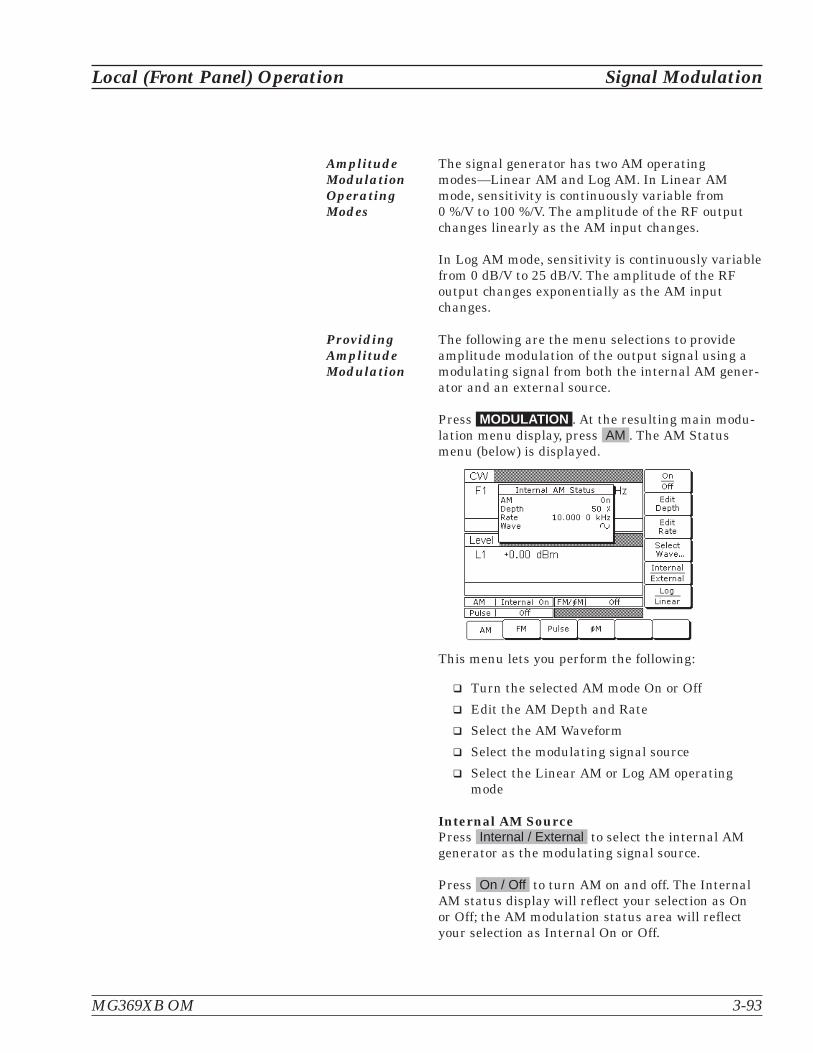
AmplitudeModulationOperatingModes
The signal generator has two AM operatingmodes—Linear AM and Log AM. In Linear AMmode, sensitivity is continuously variable from0 %/V to 100 %/V. The amplitude of the RF outputchanges linearly as the AM input changes.
In Log AM mode, sensitivity is continuously variablefrom 0 dB/V to 25 dB/V. The amplitude of the RFoutput changes exponentially as the AM inputchanges.
ProvidingAmplitudeModulation
The following are the menu selections to provideamplitude modulation of the output signal using amodulating signal from both the internal AM gener-ator and an external source.
Press MODULATION . At the resulting main modu-lation menu display, press AM . The AM Statusmenu (below) is displayed.
This menu lets you perform the following:
� Turn the selected AM mode On or Off
� Edit the AM Depth and Rate
� Select the AM Waveform
� Select the modulating signal source
� Select the Linear AM or Log AM operatingmode
Internal AM SourcePress Internal / External to select the internal AMgenerator as the modulating signal source.
Press On / Off to turn AM on and off. The InternalAM status display will reflect your selection as Onor Off; the AM modulation status area will reflectyour selection as Internal On or Off.
MG369XB OM 3-93
Local (Front Panel) Operation Signal Modulation

Press Edit Depth to open the AM Depth parameter,then edit the current value using the cursor controlkeys, rotary data knob, or enter a new value usingthe keypad and the appropriate terminator key(kHz/�s/STEPS for Linear; MHz/ms/dB for Log). TheAM Depth range is 0% to 100% in Linear and0 dB to 25 dB in Log. To close the open AM Depthparameter, press Edit Depth or make another menuselection.
Press Edit Rate to open the AM Rate parameter,then edit the current value using the cursor controlkeys, rotary data knob, or enter a new value usingthe keypad and the appropriate terminator key. TheAM rate range is 0.1 Hz to 1 MHz for sine wave and0.1 Hz to 100 kHz for square, triangle, and rampwaveforms. To close the open AM Rate parameter,press Edit Rate or make another menu selection.
Press Select Wave... to access the ModulationWaveform Selection menu (below)
This menu displays the modulation waveforms (de-scription to the left) that are available from the AMgenerator. Use the cursor control keys to highlightthe desired modulation waveform, then press Selectto select the highlighted waveform. The AM Statusdisplay will reflect your selection.
Press < Previous to return to the main AM Statusmenu display.
Press Internal / External to select the source of themodulating signal. Internal selects the modulatingsignal from the internal AM generator; external se-lects the modulating signal from an external source.The AM status display will reflect your selection.
3-94 MG369XB OM
Signal Modulation Local (Front Panel) Operation
Reduce Rate
This warning message is displayedwhen the AM Rate is set >100 kHzfor a non-sine wave modulatingwaveform. Amplitude modulationof the output signal will continuebut the modulating waveform maybe distorted.
sine wave
square wave
positive ramp
negative ramp
Gaussian noise
uniform noise
triangle wave
GN
UN

Press Log / Linear to select the AM operating mode.When Internal AM is active, the AM Depth displaywill reflect your selection as XX dB (Log) or XX %(Linear). When External AM is active, the AM Sen-sitivity display will reflect your selection as XX dB/V(Log) or XX %/V (Linear).
Press < Previous to return to the AM Status menudisplay.
External AM SourceTo provide amplitude modulation of the output sig-nal using a modulating signal from an externalsource, first set up the external signal generator andconnect it to the MG369XB rear panel AM IN con-nector.
Next, access the AM Status menu (page 3-93) andpress Internal / External to select the external sourcefor the modulating signal.
The External AM Status menu (below) is then dis-played.
This menu contains the external AM status windowthat shows the current menu selections and themeasured AM Depth (The AM depth measurementfunction measures the voltage of the external modu-lation signal and calculates the percentage modula-tion value). The menu lets you perform thefollowing:
� Turn the selected AM mode On or Off
� Edit the AM Sensitivity
� Select the modulating signal source
� Select the Linear AM or Log AM operatingmode
MG369XB OM 3-95
Local (Front Panel) Operation Signal Modulation

Press On / Off to turn AM on and off. The ExternalAM status display will reflect your selection as Onor Off; the AM modulation status area will reflectyour selection as External On or Off.
Press Edit Sensitivity to open the AM Sensitivity pa-rameter, then edit the current value using the cur-sor control keys, rotary data knob, or enter a newvalue using the keypad and the appropriate termi-nator key (kHz/ms/STEPS for Linear; MHz/ms/dBfor Log). The AM Sensitivity range is 0 %/V to100 %/V in Linear and 0 dB/V to 25 dB/V in Log. Toclose the open AM Sensitivity parameter, press EditSensitivity or make another menu selection.
Press Internal / External to select the source of themodulating signal. Internal selects the modulatingsignal from the internal AM generator; external se-lects the modulating signal from an external source.The AM status display will reflect your selection.
Press Log / Linear to select the AM operating mode.When Internal AM is active, the AM Depth displaywill reflect your selection as XX dB (Log) or XX %(Linear). When External AM is active, the AM Sen-sitivity display will reflect your selection as XX dB/V(Log) or XX %/V (Linear).
Press < Previous to return to the AM Status menudisplay.
FrequencyModulationOperatingModes
The signal generator has four FM operating modes:Locked, Locked Low-Noise, Unlocked Narrow, andUnlocked Wide. In the Locked and LockedLow-Noise FM modes, frequency modulation of theoutput signal is accomplished by summing the mod-ulating signal into the FM control path of the YIGphase-lock loop.
In Locked FM mode, the maximum FM deviation isthe lesser of �10 MHz or the rate times 300 for1 kHz to 8 MHz rates. In Locked Low-Noise FMmode, the maximum FM deviation is the lesser of�10 MHz or the rate times three for 50 kHz to8 MHz rates.
3-96 MG369XB OM
Signal Modulation Local (Front Panel) Operation
ERR
This error message is displayedwhen the external AM modulatingsignal exceeds the input voltagerange. The message “Reduce AM In-put Level” also appears at the bot-tom of the AM status display. AM isturned off until the modulating sig-nal is within the input voltagerange.

In Unlocked FM modes, the YIG phase-lock loop isdisabled to allow for peak FM deviations of up to100 MHz. In Unlocked Narrow mode, frequencymodulation is obtained by applying the modulatingsignal to the fine tuning coil of the YIG-tunedoscillator. Unlocked Narrow FM mode allowsmaximum deviations of �10 MHz for DC to 8 MHzrates.
In Unlocked Wide mode, frequency modulation is ac-complished by applying the modulating signal to themain tuning coil of the YIG-tuned oscillator. Un-locked Wide FM mode allows maximum deviationsof �100 MHz for DC to 100 Hz rates.
ProvidingFrequencyModulation
Press MODULATION . At the resulting main Modu-lation menu display, press FM . The FM Statusmenu (below) is displayed.
This menu lets you perform the following:
� Turn the selected FM mode On or Off
� Edit the FM Deviation and Rate
� Select the FM Waveform
� Select the modulating signal source
� Access the FM Mode menu
MG369XB OM 3-97
Local (Front Panel) Operation Signal Modulation

Internal FM SourceOnce you have pressed Internal / External to selectthe internal FM generator as the modulating signalsource, the Internal FM Status menu (above) is dis-played.
Press On / Off to turn FM on and off. The InternalFM status display will reflect your selection as Onor Off; the FM modulation status area will reflectyour selection as Internal On or Off.
Press Edit Deviation to open the FM Deviation pa-rameter, then edit the current value using the cur-sor control keys, rotary data knob, or enter a newvalue using the keypad and the appropriate termi-nator key. The FM Deviation range is 10 kHz to20 MHz for Locked, Locked Low-Noise, and Un-locked Narrow FM modes and 100 kHz to 100 MHzfor Unlocked Wide FM mode. To close the open FMDeviation parameter, press Edit Deviation or makeanother menu selection.
Press Edit Rate to open the FM Rate parameter,then edit the current value using the cursor controlkeys, rotary data knob, or enter a new value usingthe keypad and the appropriate terminator key. TheFM rate range is 0.1 Hz to 1 MHz for sine wave and0.1 Hz to 100 kHz for square, triangle, and rampwaveforms. To close the open FM Rate parameter,press Edit Rate or make another menu selection.
Press Select Wave... to access the ModulationWaveform Selection menu (below).
3-98 MG369XB OM
Signal Modulation Local (Front Panel) Operation

This menu displays the modulation waveforms (de-scription to the left) that are available from the FMgenerator. Use the cursor control keys to highlightthe desired modulation waveform, then press Selectto select the highlighted waveform. The FM Statusdisplay will reflect your selection.
Press < Previous to return to the main FM Statusmenu display.
Press Internal / External to select the source of themodulating signal. Internal selects the modulatingsignal from the internal FM generator; External se-lects the modulating signal from an external source.The FM status display will reflect your selection.
Press the menu soft-key Mode > . The FM Modemenu (below) is displayed.
This menu lets you select the FM operating mode.
Press Locked Low Noise to select the LockedLow-Noise FM operating mode; press Locked to se-lect the Locked FM operating mode; pressUnlocked Narrow to select the Unlocked Narrow
FM operating mode; press Unlocked Wide to selectthe Unlocked Wide FM operating mode. The FM sta-tus display will reflect your selection.
Press < Previous to return to the FM Status menudisplay.
MG369XB OM 3-99
Local (Front Panel) Operation Signal Modulation
UNLOCKED
When Unlocked Narrow FM or Un-locked Wide FM is selected ON, thiswarning message is displayed on allmenu displays to remind you thatthe carrier frequency is notphase-locked.
sine wave
square wave
positive ramp
negative ramp
Gaussian noise
uniform noise
triangle wave
GN
UN

External FM SourceTo provide frequency modulation of the output sig-nal using a modulating signal from an externalsource, first set up the external signal generator andconnect it to the MG369XB rear panel FM IN connec-tor.
Next, access the FM Status menu (page 3-97) andpress Internal / External to select the external sourcefor the modulating signal. The External FM Statusmenu (below) is then displayed.
This menu contains the external FM status windowthat shows the current menu selections and themeasured FM Deviation (The FM deviation mea-surement function measures the voltage of the ex-ternal modulation signal and calculates the peakfrequency deviation).
Press On / Off to turn FM on and off. The ExternalFM status display will reflect your selection as Onor Off; the FM modulation status area will reflectyour selection as External On or Off.
Press Edit Sensitivity to open the FM Sensitivity pa-rameter, then edit the current value using the cur-sor control keys, rotary data knob, or enter an newvalue using the keypad and the appropriate termi-nator key. The FM Sensitivity range is �10 kHz/V to�20 MHz/V for Locked, Locked Low-Noise, andUnlocked Narrow FM modes and �100 kHz/V to�100 MHz/V for Unlocked Wide FM mode. To closethe open FM Sensitivity parameter, pressEdit Sensitivity or make another menu selection.
3-100 MG369XB OM
Signal Modulation Local (Front Panel) Operation
ERR
This error message is displayedwhen the external FM modulatingsignal exceeds the input voltagerange. The message “Reduce FM In-put Level” also appears at the bot-tom of the FM status display. FM isturned off until the modulating sig-nal is within the input voltagerange.
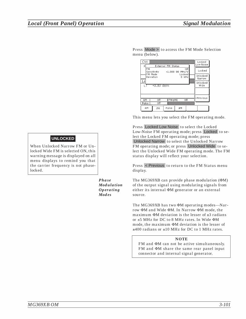
Press Mode > to access the FM Mode Selectionmenu (below).
This menu lets you select the FM operating mode.
Press Locked Low Noise to select the LockedLow-Noise FM operating mode; press Locked to se-lect the Locked FM operating mode; pressUnlocked Narrow to select the Unlocked Narrow
FM operating mode; or press Unlocked Wide to se-lect the Unlocked Wide FM operating mode. The FMstatus display will reflect your selection.
Press < Previous to return to the FM Status menudisplay.
PhaseModulationOperatingModes
The MG369XB can provide phase modulation (�M)of the output signal using modulating signals fromeither its internal �M generator or an externalsource.
The MG369XB has two �M operating modes—Nar-row �M and Wide �M. In Narrow �M mode, themaximum �M deviation is the lesser of �3 radiansor �5 MHz for DC to 8 MHz rates. In Wide �Mmode, the maximum �M deviation is the lesser of�400 radians or �10 MHz for DC to 1 MHz rates.
NOTEFM and �M can not be active simultaneously.FM and �M share the same rear panel inputconnector and internal signal generator.
MG369XB OM 3-101
Local (Front Panel) Operation Signal Modulation
UNLOCKED
When Unlocked Narrow FM or Un-locked Wide FM is selected ON, thiswarning message is displayed on allmenu displays to remind you thatthe carrier frequency is not phase-locked.
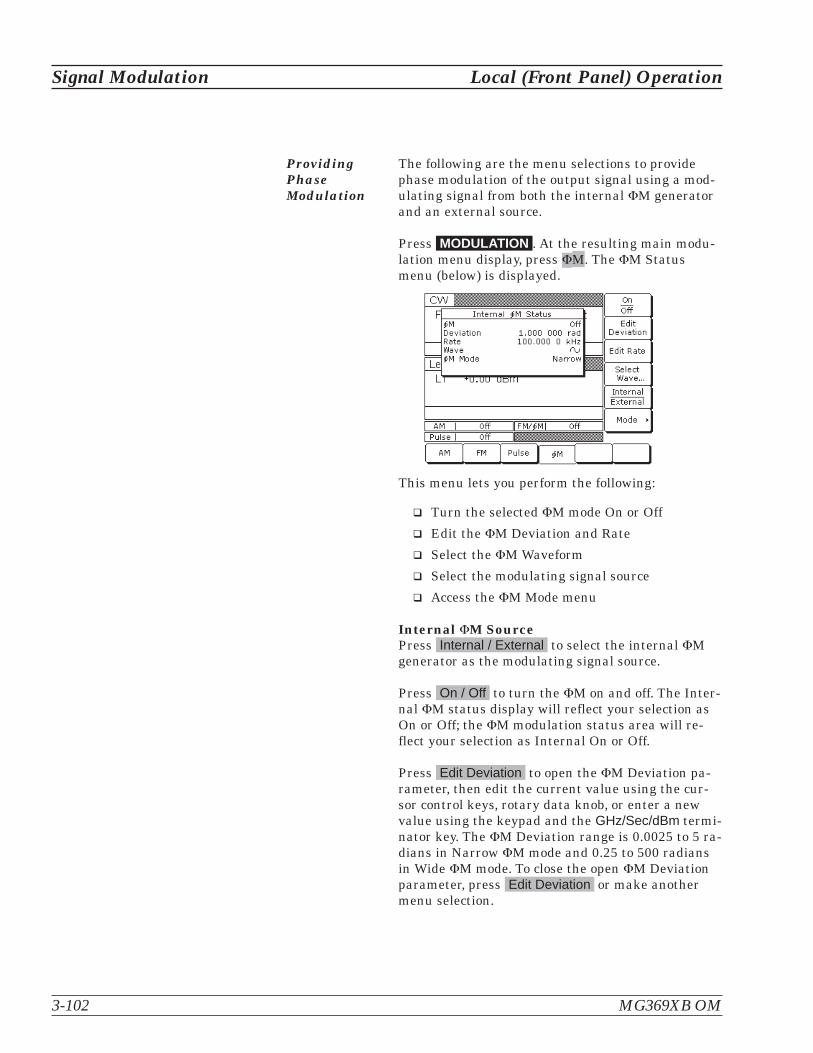
ProvidingPhaseModulation
The following are the menu selections to providephase modulation of the output signal using a mod-ulating signal from both the internal �M generatorand an external source.
Press MODULATION . At the resulting main modu-lation menu display, press �M. The �M Statusmenu (below) is displayed.
This menu lets you perform the following:
� Turn the selected �M mode On or Off
� Edit the �M Deviation and Rate
� Select the �M Waveform
� Select the modulating signal source
� Access the �M Mode menu
Internal �M SourcePress Internal / External to select the internal �Mgenerator as the modulating signal source.
Press On / Off to turn the �M on and off. The Inter-nal �M status display will reflect your selection asOn or Off; the �M modulation status area will re-flect your selection as Internal On or Off.
Press Edit Deviation to open the �M Deviation pa-rameter, then edit the current value using the cur-sor control keys, rotary data knob, or enter a newvalue using the keypad and the GHz/Sec/dBm termi-nator key. The �M Deviation range is 0.0025 to 5 ra-dians in Narrow �M mode and 0.25 to 500 radiansin Wide �M mode. To close the open �M Deviationparameter, press Edit Deviation or make anothermenu selection.
3-102 MG369XB OM
Signal Modulation Local (Front Panel) Operation

Press Edit Rate to open the �M Rate parameter,then edit the current value using the cursor controlkeys, rotary data knob, or enter a new value usingthe keypad and the appropriate terminator key. The�M Rate range is 0.1 Hz to 1 MHz for sine wave and0.1 Hz to 100 kHz for square, triangle, and rampwaveforms. To close the open �M Rate parameter,press Edit Rate or make another menu selection.
Press Select Wave... to access the ModulationWaveform Selection menu (below).
This menu displays the modulation waveforms (tothe left) that are available from the �M generator.Use the cursor control keys to highlight the desiredmodulation waveform, then press Select . The �MStatus display will reflect your selection.
Press < Previous to return to the �M Status menudisplay.
To select the �M operating mode, press Mode > .The �M Mode menu (below) is displayed.
Press Narrow to select the Narrow �M operatingmode; press Wide to select the Wide �M operatingmode. The �M status display will reflect your selec-tion.
MG369XB OM 3-103
Local (Front Panel) Operation Signal Modulation
sine wave
square wave
positive ramp
negative ramp
Gaussian noise
uniform noise
triangle wave
GN
UN
Reduce Rate
This warning message is displayedwhen the �M Rate is set >100 kHzfor a non-sine wave modulatingwaveform. Phase modulation of theoutput signal will continue but themodulating waveform may be dis-torted.

Press < Previous to return to the �M Status menudisplay.
External �M SourceTo provide phase modulation of the output signalusing a modulating signal from an external source,first set up the external signal generator and con-nect it to the MG369XB rear panel FM/�M IN con-nector.
Next, from the �M Status menu, press Internal / Ex-ternal to select the external source for the modulat-ing signal. The External �M Status menu (below) isthen displayed.
This menu contains the external �M status windowthat shows the current menu selections and themeasured �M deviation (The �M deviation mea-surement function measures the voltage of the ex-ternal modulation signal and calculates the peakfrequency deviation). This menu lets you performthe following:
� Turn the selected �M mode On or Off
� Edit the �M sensitivity
� Select the modulating signal source
� Access the �M Mode menu
3-104 MG369XB OM
Signal Modulation Local (Front Panel) Operation

Press On / Off to turn �M on and off. The external�M status display will reflect your selection as Onor Off; the �M modulation status area will reflectyour selection as External On or Off.
Press Edit Sensitivity to open the �M sensitivity pa-rameter, then edit the current value using the cur-sor control keys, rotary data knob, or enter a newvalue using the keypad and the appropriate termi-nator key. The �M Sensitivity range is �0.0025 radi-ans/V to �5 radians/V for Narrow �M mode and�0.25 radians/V to �500 radians/V for Wide �Mmode. To close the open �M Sensitivity parameter,press Edit Sensitivity or make another menu selec-tion.
To select the �M operating mode, press Mode > .The �M Mode menu (below) is displayed.
Press Narrow to select the Narrow �M operatingmode; press Wide to select the Wide �M operatingmode. The �M status display will reflect your selec-tion.
Press < Previous to return to the �M Status menudisplay.
MG369XB OM 3-105
Local (Front Panel) Operation Signal Modulation
ERR
This error message is displayedwhen the external �M modulatingsignal exceeds the input voltagerange.The message “Reduce �M In-put Level” also appears at the bot-tom of the �M status display. �M isturned off until the modulating sig-nal is within the input voltagerange.
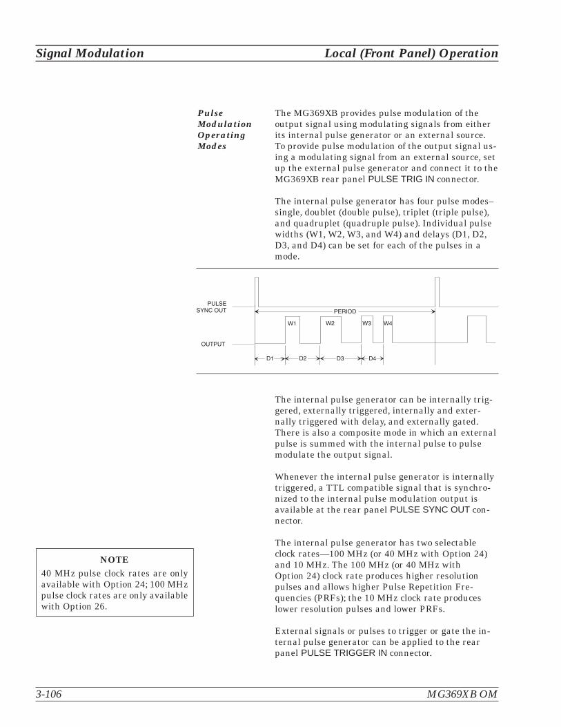
PulseModulationOperatingModes
The MG369XB provides pulse modulation of theoutput signal using modulating signals from eitherits internal pulse generator or an external source.To provide pulse modulation of the output signal us-ing a modulating signal from an external source, setup the external pulse generator and connect it to theMG369XB rear panel PULSE TRIG IN connector.
The internal pulse generator has four pulse modes–single, doublet (double pulse), triplet (triple pulse),and quadruplet (quadruple pulse). Individual pulsewidths (W1, W2, W3, and W4) and delays (D1, D2,D3, and D4) can be set for each of the pulses in amode.
The internal pulse generator can be internally trig-gered, externally triggered, internally and exter-nally triggered with delay, and externally gated.There is also a composite mode in which an externalpulse is summed with the internal pulse to pulsemodulate the output signal.
Whenever the internal pulse generator is internallytriggered, a TTL compatible signal that is synchro-nized to the internal pulse modulation output isavailable at the rear panel PULSE SYNC OUT con-nector.
The internal pulse generator has two selectableclock rates—100 MHz (or 40 MHz with Option 24)and 10 MHz. The 100 MHz (or 40 MHz withOption 24) clock rate produces higher resolutionpulses and allows higher Pulse Repetition Fre-quencies (PRFs); the 10 MHz clock rate produceslower resolution pulses and lower PRFs.
External signals or pulses to trigger or gate the in-ternal pulse generator can be applied to the rearpanel PULSE TRIGGER IN connector.
3-106 MG369XB OM
Signal Modulation Local (Front Panel) Operation
PERIOD
D1 D2 D3
OUTPUT
PULSESYNC OUT
W1 W2 W4 W3
D4
NOTE40 MHz pulse clock rates are onlyavailable with Option 24; 100 MHzpulse clock rates are only availablewith Option 26.
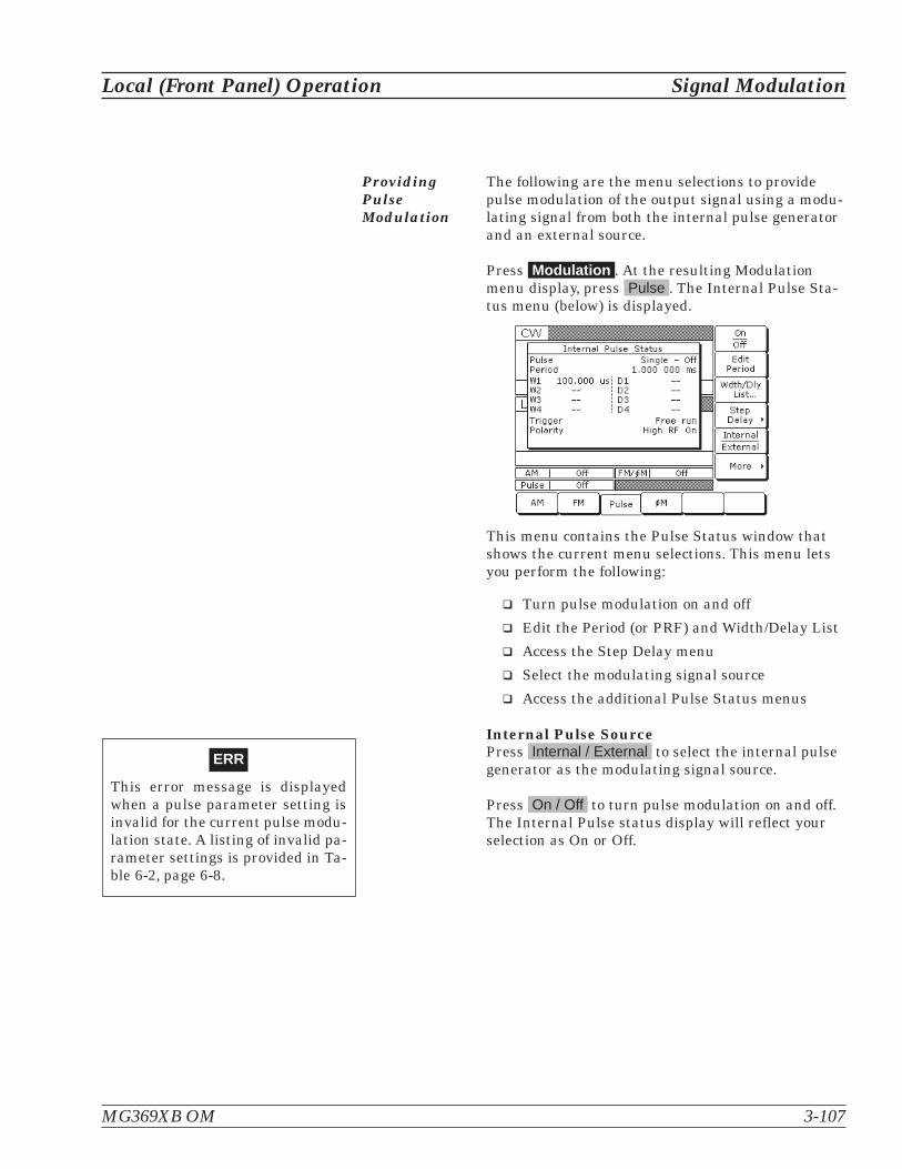
ProvidingPulseModulation
The following are the menu selections to providepulse modulation of the output signal using a modu-lating signal from both the internal pulse generatorand an external source.
Press Modulation . At the resulting Modulationmenu display, press Pulse . The Internal Pulse Sta-tus menu (below) is displayed.
This menu contains the Pulse Status window thatshows the current menu selections. This menu letsyou perform the following:
� Turn pulse modulation on and off
� Edit the Period (or PRF) and Width/Delay List
� Access the Step Delay menu
� Select the modulating signal source
� Access the additional Pulse Status menus
Internal Pulse SourcePress Internal / External to select the internal pulsegenerator as the modulating signal source.
Press On / Off to turn pulse modulation on and off.The Internal Pulse status display will reflect yourselection as On or Off.
MG369XB OM 3-107
Local (Front Panel) Operation Signal Modulation
ERR
This error message is displayedwhen a pulse parameter setting isinvalid for the current pulse modu-lation state. A listing of invalid pa-rameter settings is provided in Ta-ble 6-2, page 6-8.

Press Edit Period to open the Pulse Period parame-ter. (If you had selected PRF instead of Period at theInternal Pulse Configuration menu, the soft-keywould read Edit PRF and pressing it would openthe PRF parameter.) Edit the current value usingthe cursor control keys, rotary data knob, or enter anew value using the keypad and the appropriateterminator key. To close the Pulse Period parameter,press Edit Period (or Edit PRF ) or make anothermenu selection.
Press Wdth / Dly List... to display the PulseWidth/Delay List menu (below) of current PulseWidth (W1-W4) and Delay (D1-D4) parametersettings.
To change the current value of a parameter, use thecursor control keys to select the parameter, thenpress Edit Selected . Edit the current value usingthe cursor control keys, rotary data knob, or enter anew value using the keypad and the appropriateterminator key. To close the open parameter, pressEdit Selected or < Previous .
When the Delayed or Triggered w/delay triggermode is selected, the menu display adds the soft-keyStep Delay . This soft-key lets you access menus for
setting the step delay parameters and turning theStepped Delay Mode on and off. The Stepped DelayMode is described on page 3-113.
3-108 MG369XB OM
Signal Modulation Local (Front Panel) Operation
NOTEAt a 100 MHz pulse clock rate, thepulse period must be 50 ns longerthan the pulse widths + delays; at a40 MHz pulse clock rate, the pulseperiod must be 125 ns longer thanthe pulse widths + delays; at a10 MHz pulse clock rate, the pulseperiod must be 500 ns longer thanthe pulse widths + delays.
NOTEPulse Delay (D1) is only activewhen Delayed or Triggered w/delaytriggering mode is selected.

Press More > to access the additional InternalPulse Status menu display (with Option 26, belowleft; with Option 24, below right).
This menu allows you to perform the following:
� Access the Pulse Mode menu
� Access the Trigger Mode menu
� Configure the internal pulse display(Period or PRF)
� Select the polarity of the pulse input signal(Low or High) that turns on the RF
� Select the pulse generator’s clock rate
Press Mode... to access the Pulse Mode menu dis-play (below).
This menu displays the pulse modes (Single, Dou-blet, Triplet, and Quadruplet) that are availablefrom the pulse generator. Use the cursor controlkeys to highlight the desired pulse mode, then selectit by pressing Select . The Internal Pulse Statusdisplay will reflect your selection.
Press < Previous to return to the additional Inter-nal Pulse Status menu display.
MG369XB OM 3-109
Local (Front Panel) Operation Signal Modulation
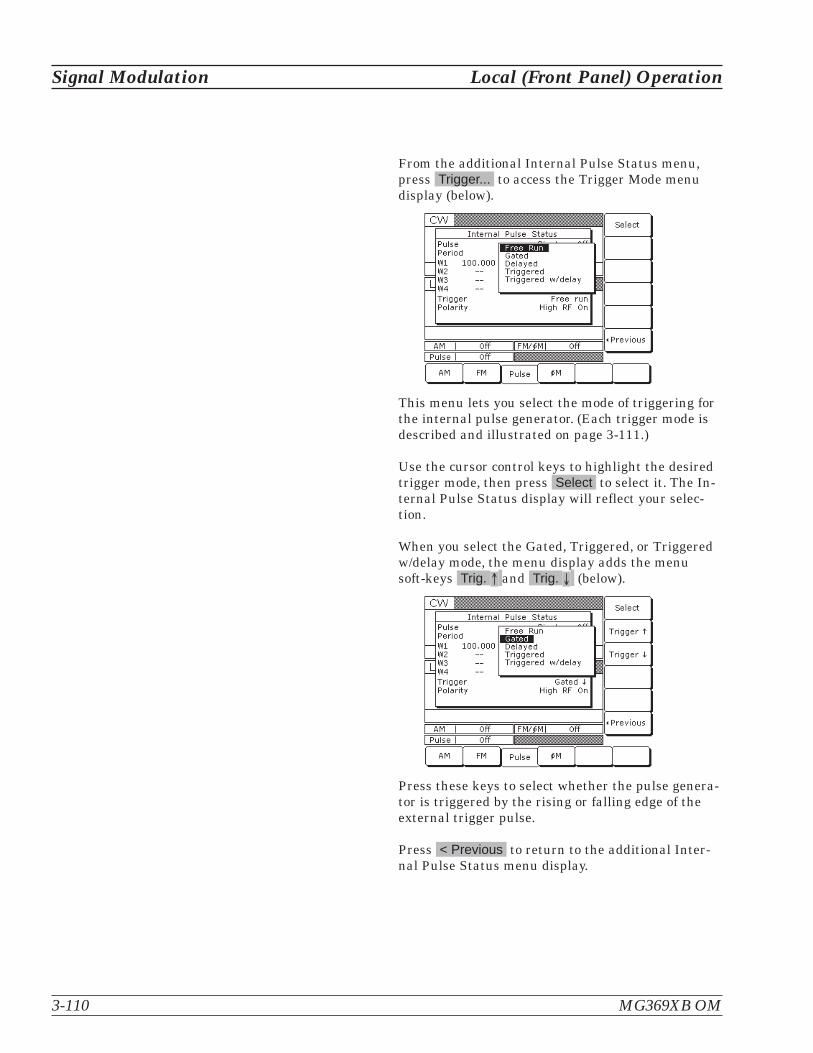
From the additional Internal Pulse Status menu,press Trigger... to access the Trigger Mode menudisplay (below).
This menu lets you select the mode of triggering forthe internal pulse generator. (Each trigger mode isdescribed and illustrated on page 3-111.)
Use the cursor control keys to highlight the desiredtrigger mode, then press Select to select it. The In-ternal Pulse Status display will reflect your selec-tion.
When you select the Gated, Triggered, or Triggeredw/delay mode, the menu display adds the menusoft-keys Trig. � and Trig. (below).
Press these keys to select whether the pulse genera-tor is triggered by the rising or falling edge of theexternal trigger pulse.
Press < Previous to return to the additional Inter-nal Pulse Status menu display.
3-110 MG369XB OM
Signal Modulation Local (Front Panel) Operation

� � � � � � �
� � � � �
� � � � � �
� � � � � � �
� � � � � �
� � � � � �
� � � � �
� � � � �
� � � � � � �
� � � � � �
� � � � �
� � � � � � �
� � � � � �
� � � � � �
� � � � � � �
� � � � � � �
� � � � � �
� � � � � �
� � � � � � � � � � � � � �
� � � � � � � � �
� � � � �
� � � � � �
Free Run–The pulse generator produces Single, Doublet, Triplet, or Quadrupletpulse modulation waveforms at the internal pulse repetition rate. Pulse delay(D1) is not available in this trigger mode.
Delayed–The pulse generator produces Single, Doublet, Triplet, or Quadrupletpulse modulation waveforms delayed by pulse delay (D1) at the internal pulserepetition rate.
Triggered–The pulse generator is triggered by an external trigger to produceSingle, Doublet, Triplet, or Quadruplet pulse modulation waveforms. Pulse de-lay (D1) is not available in this trigger mode.
Triggered w/delay–The pulse generator is triggered by an external trigger toproduce Single, Doublet, Triplet, or Quadruplet pulse modulation waveforms de-layed by pulse delay (D1).
Gated– An external pulse gates the internal pulse generator on and off. Whengated on, the pulse generator produces a Single pulse modulation waveform atthe internal pulse repetition rate. Doublet, Triplet, and Quadruplet pulse modesare not available in this trigger mode.
For proper operation, the period of the external pulse must be greater than thesum of the pulse repetition rate and pulse width of the internal pulse modula-tion waveform. To prevent relative timing jitter, the external gating pulsesource can be synchronized with the internal pulse generator by using the10 MHz REF OUT signal output (MG369XB rear panel) as a frequency referencefor the external generator.
Local (Front Panel) Operation Signal Modulation
MG369XB OM 3-111
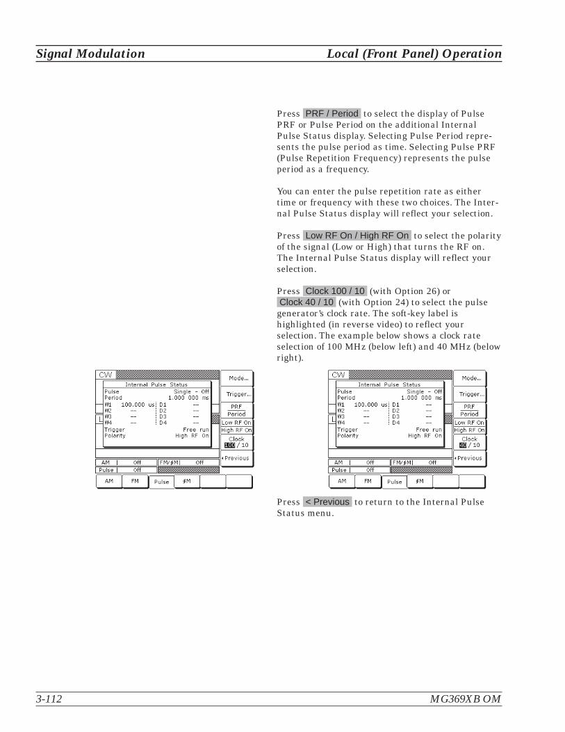
Press PRF / Period to select the display of PulsePRF or Pulse Period on the additional InternalPulse Status display. Selecting Pulse Period repre-sents the pulse period as time. Selecting Pulse PRF(Pulse Repetition Frequency) represents the pulseperiod as a frequency.
You can enter the pulse repetition rate as eithertime or frequency with these two choices. The Inter-nal Pulse Status display will reflect your selection.
Press Low RF On / High RF On to select the polarityof the signal (Low or High) that turns the RF on.The Internal Pulse Status display will reflect yourselection.
Press Clock 100 / 10 (with Option 26) orClock 40 / 10 (with Option 24) to select the pulse
generator’s clock rate. The soft-key label ishighlighted (in reverse video) to reflect yourselection. The example below shows a clock rateselection of 100 MHz (below left) and 40 MHz (belowright).
Press < Previous to return to the Internal PulseStatus menu.
3-112 MG369XB OM
Signal Modulation Local (Front Panel) Operation

Stepped Delay ModeThe Stepped Delay Mode lets you automatically in-crement or decrement the Pulse Delay 1 (D1) valueaccording to step delay parameters. The mode isonly available when the Delayed or Triggered w/de-lay triggering mode is selected. Selecting either trig-gering mode adds the soft-key Step Delay > to theInternal Pulse Status menu. Refer to page 3-110 forsetting the triggering options.
From the Internal Pulse menu, press Step Delay >to access the Step Delay Mode menu (below).
This menu allows you to perform the following:
� Turn step delay on/off
� Edit the step delay parameters
� Set the length of time a Delay 1 (D1) time isapplied before it is incremented or decrement-ed by the step size
Open the parameter you wish to change, then editthe current value using the cursor control keys orthe rotary data knob or enter a new value using thekey pad and appropriate termination key. When youhave finished setting the open parameter, close it bypressing its menu soft-key or make another menuselection.
Press On/Off to turn the Stepped Delay Mode onand off.
Press Start Delay to open the Delay 1 (D1) starttime parameter.
Press Stop Delay to open the Delay 1 (D1) end timeparameter.
MG369XB OM 3-113
Local (Front Panel) Operation Signal Modulation
NOTEIf the set Step Delay parameters re-sult in a fractional number of incre-ments, then the last (fractional) oneis not taken.
Press Step Size to open the step size time parame-ter.
Press Step Time to open the dwell-time-per-step pa-rameter, then edit the current value using the cur-sor control key, rotary data knob, or enter a newvalue using the keypad and appropriate terminationkey. To close the open parameter, press Step Timeor make another menu selection.
Press < Previous to return to the Internal PulseStatus menu display.
Start Delay and End Delay times may be from lowerto higher times or vice versa.
The Step Size time will be applied as an incrementor a decrement as appropriate.
During pulse modulation, when the step delay modeis on, both Start Delay and Stop Delay times are er-ror checked as Delay 1 (D1) times against otherpulse parameters. Step Size time is checked againstthe Start Delay and Stop Delay times and must beno greater than the difference between Start Delayand Stop Delay.
3-114 MG369XB OM
Signal Modulation Local (Front Panel) Operation

External Pulse SourceTo provide pulse modulation of the output signalusing a modulating signal from an external source,first set up the external pulse generator and connectit to the MG369XB rear panel PULSE TRIGGER INconnector.
Next, access the Internal Pulse Status menu(page 3-107) and press Internal / External to selectthe external source for the modulating signal. TheExternal Pulse Status menu (below) is then dis-played.
This menu contains the external pulse statuswindow that shows the current menu selections.This menu lets you perform the following:
� Turn the external pulse modulation on and off
� Select the modulating signal source
� Select the polarity of the pulse input signal(Low or High) that turns on the RF
Press On / Off to turn pulse modulation on and off.The External Pulse Status display will reflect yourselection as On or Off; the Pulse modulation statusarea will reflect your selection as External On orOff.
Press Internal / External to select the source of themodulating signal. The External Pulse Statusdisplay will reflect your selection.
Press Low RF On / High RF On to select the polarityof the signal (Low or High) that turns the RF on.The External Pulse Status display will reflect yourselection.
MG369XB OM 3-115
Local (Front Panel) Operation Signal Modulation

3-17 Internal PowerMeter (Option 8)
The internal power meter function, added by Option 8, lets you mea-sure the power from a test device and display its value in the lowerright corner of the level parameters area of the front panel LCD. Thepower measurement function has a range of +16 dBm to –35 dBm andis compatible with Anritsu 560-7, 5400-71, and 6400-71 series detec-tors.
To make a measurement of the power from a testdevice using the internal power measurement func-tion, first connect the detector to the test device andto the rear panel POWER METER connector.
Next, press the SYSTEM key. At the System menu(below), press Measure Power to enable the powermeasurement function.
During operation, the power level is displayed nearthe Level parameter in all main menu displays (be-low).
If the power level exceeds the operating limitationsof the instrument or RF detector, the word PwrUnderrange is displayed to indicate an under rangecondition; the word Pwr Overrange is displayed to in-dicate an over range condition.
3-116 MG369XB OM
Internal Power Meter (Option 8) Local (Front Panel) Operation

The internal power meter’s accuracy can be im-proved by enabling a power meter offset or by run-ning an internal power meter calibration routine.
Enable a power meter offset by selecting Pwr MeterOffset and entering a non-zero power level offsetvalue (below).
The word Offset is displayed when a non-zero offsetvalue is entered (below).
MG369XB OM 3-117
Local (Front Panel) Operation Internal Power Meter (Option 8)

To calibrate the internal power meter, connect theRF detector to the MG369XB’s RF Output connectorand select Detector Cal > to enter the Detector Cali-bration menu (below).
From the Detector Calibration menu, press Start Calto begin the calibration (below).
After the calibration completes, the correction canbe enabled by pressing the Enable key. The status isdisplayed in the Detector Calibration menu as On orOff.
To disable the calibration correction, press Enableagain.
Press <Previous to return to the System menu.
To disable the power measurement function, pressMeasure Power again.
3-118 MG369XB OM
Internal Power Meter (Option 8) Local (Front Panel) Operation

3-18 Scan Modulation(Option 20)
The internal scan modulator, added by Option 20, lets you amplitudemodulate output signals from 2 to 18 GHz at modulation depths up to60 dB. Scan modulation is accomplished using a modulating signalfrom an external source and is in addition to the normal amplitudemodulation described in Section 3-12.
To provide amplitude modulation of the output sig-nal using the internal scan modulator, first set upthe external modulating signal generator and con-nect it to the MG369XB’s rear panel SCAN MOD INconnector.
Next, press MODULATION, then Scan to go to theScan Status menu (below).
Press On/Off to turn scan modulation on and off. TheScan status display and the Scan modulation statusarea will reflect your selection as On or Off.
Control the scan modulation depth by varying thelevel of the external modulating signal. The scanmodulator has a fixed sensitivity of –10 dB/V. An ex-ternal modulating signal level of 6 volts producesthe maximum modulation depth of –60 dB.
MG369XB OM 3-119/3-122
Local (Front Panel) Operation Scan Modulation (Option 20)


Table of Contents
4-1 Introduction . . . . . . . . . . . . . . . . . . . . . . . . . . . . . . 4-3
4-2 Menu Map Description. . . . . . . . . . . . . . . . . . . . . . . . . 4-3
Chapter 4Local Operation—Menu Maps


Chapter 4Local Operation—Menu Maps
4-1 Introduction This chapter provides menu maps that support the MG369XB frontpanel operating instructions found in Chapter 3. It includes menumaps for all of the frequency and power level modes of operation. Inaddition, a menu map for system configuration is also provided.
4-2 Menu MapDescription
A menu map shows the menu key selections and instrument menu dis-plays for a particular mode of signal generator operation. The menudisplays are shown as they appear on the instrument and are linkedtogether to show the sequence of menu selection. A brief description ofthe function of each menu's soft-keys is provided. If a menu soft-keyselects another menu, then it is shown linked to that menu. Fig-ure 4-1, on page 4-5, is a sample menu map annotated to identify thekey elements.
The following is a list of the menu maps contained in this chapter.
Figure Title Page
4-1 Sample Menu Map . . . . . . . . . . . . . . . . . . . . 4-5
4-2 CW Frequency Mode Menu Map . . . . . . . . . . . . . 4-6
4-3 Analog Sweep Frequency Mode Menu Map . . . . . . . 4-7
4-4 Step Sweep Frequency Mode Menu Map. . . . . . . . . 4-8
4-5 Manual Sweep Frequency Mode Menu Map . . . . . . . 4-9
4-6 List Sweep Frequency Mode Menu Map . . . . . . . . 4-10
4-7 Fixed Power Level Mode Menu Map . . . . . . . . . . 4-11
4-8 CW Power Sweep Mode Menu Map . . . . . . . . . . . 4-12
4-9 Sweep Frequency/Step Power Mode Menu Map . . . . 4-13
4-10 Leveling Modes Menu Map . . . . . . . . . . . . . . . 4-14
4-11 Amplitude Modulation Modes Menu Map . . . . . . . 4-15
4-12 Frequency Modulation Mode Menu Map . . . . . . . . 4-16
4-13 Phase Modulation Mode Menu Map . . . . . . . . . . 4-17
4-14 Pulse Modulation Mode Menu Map . . . . . . . . . . . 4-18
4-15 System Configuration Menu Map . . . . . . . . . . . . 4-19
MG369XB OM 4-3/4-4


LOCAL OPERATION SAMPLE–MENU MAPS MENU MAP
MG369XB OM 4-5
Figure 4-1. Sample Menu Map (Annotated)
� � � � � � � � � � � � � � � �� � � � � � � � � � � � � � � � � � �
� � � � �
� � � � � � � � � � � � � �� � � � � � � � � � �
� � � � � � � � � � � � � � � �
� � � � � � � � � � � � �� � � � �
� � � � � � � � �� � � � �
� � � � � � � � � � �� � � � �
� � � � � � � ! � �� � � � � � � � � � �
� � � � � � � � � � � � � � � � � �
� � � � � � � � � � � � � � � �
� � � � � � � � � � � � � � � � � �
� � � � " � # � $ � � % �& � � � � ' � � (
� � � � � � � ) � � � � � � �
� � � � � � � % � � � � � � � � � �
% � � � � � � � � � � � � * *
� � � � � � � + � � � � � � � �� � � � � � �
� � � � � � � � � � � � � � � � �& � � � � ' � � (
� � � � ' � � � � * * � � � % �& � � � � ' � � (
� � � � � � � � � � � � � � � � �� � � � � � � � � � � � � � � � � � � �
� � � � � � � � � � � � � � � � � � � � � � � � � � � � � � �� � � � � � � � � � � � � � � � � � � � � � � � �
� � � � � � � � � � � �
� � � � � � � � � � � � � � � � � � � � � � � � � � � � � � � � � � � � � � � � � � � � � �� � � � � � � � � � � � � � � � � � � �� � � � � � � � � � � � � � � � � � � � � � � � �� � �
! � � � " # � � � � � � � � � � $ � � � � � � � � � � � � � � � � � � � � � � � � � � � � � � � � � � � � � � � � � � � � � � � � � � � � � � � � % ! & � � � � � � � � � � � � � � � � � � � � � � � � � � � � � � � � � � � � % � � ' � � � � � � � � � � � � � ( � � � � � � � � � � � � � � � � � � � � � � � � � � � % ! ) % � � � � � � � � � � � '
� � � � � � � � � � � �* � � � � � � � � � � � � � � � � � � � � � � � � � � � � � � � � � � � � � +
� � � � � � � � � � � � � � � � � � � � � � � �* � � � � � � � � � � � � � � � � � �� � � � � � � � � � � � � � � � � � � +
� � � � � � � �

CW LOCAL OPERATIONFREQUENCY MODE –MENU MAPS
4-6 MG369XB OM
� � � � � � � � � � � � � �� � � � � � � � � � �
� � � � � � � � � � � � � � � �
� � � � � � � � � � � � �� � � � �� � � � � � � � �� � � � �
� � � � � � � � � � �� � � � �
� � � � � � � ! � �� � � � � � � � � � �
� � � � � � � � � �� � � � � � �
� � � � � � � � � � � � � � � �
� � � � � � � � � � � � � � � � � �
� � � * *
� � � � � � � ) � � � � � � �
� � � � � � � % � � � � � � � � � �
% � � � � � � � � � � � � * *
� � � � � , � � ' � � ' � �� � � � �
� � � � � � � � � � � �� * * � � � � � - . / 0 � 1 ! + � % � �
� � � � � � � � � � � � � � � � - . / 0 � 1 ! + � % � �
� � � � � � � + � � � � � � � �� � � � � � �
� � � � � � � � � � � � � � � �� � � � � � � � � � � � � � � � � � �
� � � � �
� � � � � " � # � $ � � � � � * *
� � � � � � ' � � � � * * � �
2 � � � � ' � � � � * * � � � ) � � � � �
� � � � � � " � # � $ � � � � �� � $
Figure 4-2. CW Frequency Mode Menu Map
NOTESRefer to Chapter 3, page 3-20, for CW fre-quency mode operating instructions.
Refer to Chapter 7, page 7-4, for mas-ter-slave operating instructions.

MG369XB OM 4-7
LOCAL OPERATION ANALOG SWEEP–MENU MAPS FREQUENCY MODE
Frequency
Alternate Sweep On/Off
Select Auto Trigger
Select External Trigger
Select Single Trigger
Edit Current Start Frequency
Edit Current Stop Frequency
Edit Current Sweep Time
Edit Alternate Sweep Start Frequency
Edit Main Sweep Power Level
Edit Alternate Sweep Power Level
Edit Current Power Level
Edit Alternate Sweep Stop Frequency
Triggers a Single Sweep
Alternate Sweep ON
Figure 4-3. Analog Sweep Menu Map
NOTERefer to Chapter 3, page 3-26,for analog sweep frequencymode operating instructions.

4-8 MG369XB OM
� � � 0 � � � � �� � � $ � + � � � � �% � � ) � � � � �
� � � � �
� � � � � � � % � � 3 � � � � � � * *
� � � � � � � � � � � �
� � � � � � � � � � � $
� � � � � � � � � � � � � � � � � � �
� � � � � � � � � � � � � � � �
� � � � � � � � � � � � �
� � � � � ) � � � � $
� � � � � * *
� � � � � * *
� � � � � * *
� � � � � * *
� � � � � � � � � � � 4
� � � � � ! � $ 5 � � � * � � � � �
� � � � � � � � � � � � � � � �
� � � � � � � � � � � � �
� � � � � � � � � � � �
� � � � � � � � � � � � �% � � 3 � � � � � � �
� � � � � � � � �% � � 3 � � � � � � �
1 � � � � % � � 3 � � � � � � * *
� � � � � + � � � � �� � � � � � � � � � �
� � � � � + � � � � �� � � � � � � �
� � � � � % � � � � � �� � � � � � �
� � � � � + � � � � �� � � � � � �
NOTERefer to Chapter 3,page 3-26,for step sweep frequencymode operating instructions.
Figure 4-4. Step Sweep Frequency Mode Menu Map
STEP SWEEP LOCAL OPERATIONFREQUENCY MODE –MENU MAPS

MG369XB OM 4-9
� � � � �
� � � � � � � � � � � � � � � �
� � � � � � � � � � � � �
� � � � � � � � � � � � � � � �
� � � � � � � � � � � � �
� � � � � � � � � � � �
� � � � � � � � � � � 4
� � � � � ! � $ 5 � � � * � � � � �
NOTERefer to Chapter 3, page 3-32,for manual sweep frequencymode operating instructions.
Figure 4-5. Manual Sweep Frequency Mode Menu Map
LOCAL OPERATION MANUAL SWEEP–MENU MAPS FREQUENCY MODE

4-10 MG369XB OM
� � � � � � � � � � � � � � � � ' � � � � � � � � * � �
+ � � � � � � � � � � � � � � � � � � � � � � � � � � � �
� � � � � � � � � � � � �
� � � � � � � � � � � � �
� � � � � � � � � � � � � �
� � � � � ) � � � � $
� � � � � � � � � � � � � � � � �
� � � � � + � � � � � � � � � �
� � � � � � � � � � � � � � �
� � � � � % � � � � � � � � � �
� � � � � , � � ' � � ' � � � � � � � � � � � �
� � � � � � � � ) � � � � � � � � � � � � � � 6 / � � � � � � �
� � � � � � � � ) � � � � � � ! � � � 6 / � � � � � � �
� � � � �
� � � � � � � � � � � � �� � � � � � � � � � �
� � � � � ) * � � � � � � � � � � + �
� � � � � � � � � � � � � � � � � � � � � � � � �
) � � � � � � � � � � � � � � � �
� � � � � , � � ' � � ' � � � � � � � � � � � � � �
� � � � � � � � ) � � � � � � � � � � � � � � 7 / � � � � � � � � �
� � � � � � � � ) � � � � � � ! � � � 7 / � � � � � � � � �
� � � � � ) * � � � � � � � � � � + �
� � � � � � � � � � � � � � � � � � � � � � � � �
) � � � � � � � � � � � � � � � �
NOTERefer to Chapter 3,page 3-42,for list sweep frequency modeoperating instructions.
Figure 4-6. List Sweep Frequency Mode Menu Map
LIST SWEEP LOCAL OPERATIONFREQUENCY MODE –MENU MAPS

MG369XB OM 4-11
NOTERefer to Chapter 3, page 3-51 forfixed power level mode operatinginstructions.
Figure 4-7. Fixed Power Level Mode Menu Map
LOCAL OPERATION FIXED POWER–MENU MAPS LEVEL MODE

4-12 MG369XB OM
� �
� � � � � � � � � � � � � � � 0 $ � & � � (
� � � � � � � � � � � � � � � 0 � 1 � & � � (
� � � � � � � � � � � � � � $ 1 � & � � � (
� � � � � � � � � � � 4
� � � � � ) � � � � $
� � � � � ! � $ 5 � � � * � � � � �
� � � � � � � � � � � � � � �
� � � � � � � � � � � � � � � � � � � � � * *
� � � * *
� � � * *
� � � � � � � � � � � � � � �
� � � � � � � � � � � � � � � � � �
NOTERefer to Chapter 3, page 3-56, forCW power sweep mode operat-ing instructions.
Figure 4-8. CW Power Sweep Mode Menu Map
CW POWER LOCAL OPERATIONSWEEP MODE –MENU MAPS

MG369XB OM 4-13
NOTERefer to Chapter 3, page 3-61, forsweep frequency/step power modeoperating instructions.
Figure 4-9. Sweep Frequency/Step Power Mode Menu Map
LOCAL OPERATION SWEEP FREQUENCY/–MENU MAPS STEP POWER MODE

4-14 MG369XB OM
� � � � � � ' � � � � � � � � � � � � � � � � � � �
� � � � � � ' � � � � � � � � * * � � � 1 � �
� � � � � + � � � � � � � � � ; � � & + � � � � * * (
� �
� � � � � � � � + � < � � � � � � � * *
� � � � � � ' � � � � � � � � � � � � � � �
� � � � � � ' � � � � � + � < � � �
� � � � � � � � � � � � � � � � � �
) � � � � � � ' � + � � � � � � �� � � $ � � ' � + � �� � � � � � � � � � � � � + � � � � � � � � & 7 / � 0 � � � � � (
� � � � � � � � ) � � � � + � � � � � � � � & 7 / � 0 � � � � � (
� � � � � � � � � � + � �& ) * � � � � % � � (
� � � � � � � � � � � + � �� � � � � � ) � � � � � � � � � �
� � � � � � � � � � � + � �� � � � � % � � � � � � �
� � � � � � � � � � ; � � � & + � � � � * * (
� � � � � � ' � � � � � � � � � � � �
� � � � � � ' � � � � � � � � � � �
� � � � � � ' � ! � $ 5 � � � * � � � � � �
� � � � � � * * � � � � � 5 � � � � * *
� � � � � � � � � � 5 � � � � � � � � � � � � � � * * � � � � � 5
NOTERefer to Chapter 3, page 3-63, forleveling modes operating instruc-tions.Figure 4-10. Leveling Modes Menu Map
LEVELING LOCAL OPERATIONMODES –MENU MAPS

Modulation
AM On/Off
Edit AM Sensitivity
Select Internal AM SourceSelect Log AM (0 to 25 dB/V) or
Linear AM (0 to 100%/V)
Select Log AM (0 to 25 dB/V) orLinear AM (0 to 100%/V)
Select External AM Source
Edit AM RateEdit AM DepthAM On/Off Select Modulation Waveform
Note: Use the keypad cursorkeys to highlight thewaveforms.
Internal AM
External AM
Figure 4-11. Amplitude Modulation Menu Map
NOTERefer to Chapter 3, page 3-93,for amplitude modulation op-erating instructions.
LOCAL OPERATION AMPLITUDE MODULATION–MENU MAPS MODE
MG369XB OM 4-15

FREQUENCY MODULATION LOCAL OPERATIONMODE –MENU MAPS
4-16 MG369XB OM
Modulation
FM On/Off
Edit FM Sensitivity
Select Internal FM Source
Select External FM Source
Edit FM Rate
Edit FM Deviation
FM On/Off Select Modulation Waveform
Note: Use the keypad cursorkeys to highlight thewaveforms.
Internal FM
External FM
Select Locked Low-Noise FM Mode
Select Locked FM Mode
Select Unlocked Narrow FM Mode
Select Unlocked Wide FM Mode
Select Locked Low-Noise FM Mode
Select Locked FM Mode
Select Unlocked Narrow FM Mode
Select Unlocked Wide FM Mode
Figure 4-12. Frequency Modulation Menu Map
NOTERefer to Chapter 3, page 3-96,for frequency modulation op-erating instructions.

LOCAL OPERATION PHASE MODULATION–MENU MAPS MODE
MG369XB OM 4-17
Modulation
�M On/Off
Edit M Sensitivity�
Select Internal M Source�
Select External M Source�
Edit M Rate�
Edit M Deviation�
�M On/Off Select Modulation Waveform
Note: Use the keypad cursorkeys to highlight thewaveforms.
Internal M�
External M�
Select Narrow M Mode�
Select Wide M Mode�
Select Narrow M Mode�
Select Wide M Mode�
NOTERefer to Chapter 3, page 3-101,for phase modulation operat-ing instructions.
Figure 4-13. Phase Modulation Menu Map

PULSE MODULATION LOCAL OPERATIONMODE –MENU MAPS
4-18 MG369XB OM
Modulation
Pulse Modulation On/Off
Select Internal Pulse Source
Select Low Level Trigger orHigh Level Trigger
Turn Step Delay On/Off
Edit Selected PulseWidth or Delay
Internal Pulse Modulation
External Pulse Modulation
Select Pulse Modulation Trigger Mode
Select Pulse Modulation Mode
Select PRF or Period
Select Low Level Trigger orHigh Level Trigger
Select 100 MHz or 10 MHzPulse Generator Clock**
Note: Use the keypad cursorkeys to highlight thepulse mode.
Note: Use the keypad cursorkeys to highlight thetrigger mode.
Select External Pulse Source
Pulse Modulation On/Off
Edit PRF
Note: Use the keypad cursorkeys to highlight thefields.
*
* The Step Delay Menu is only availablewhen Delayed or Triggered with Delaytriggering modes are selected.
** 100 MHz pulse clock rates are availablewith Option 26; 40 MHz pulse clock ratesare available with Option 24.
Set Step Delay Start Time
Set Step Delay Stop Time
Set Step Delay Step Size
Set Step Delay Time
Set Negative Edge Trigger
Set Positive Edge Trigger
NOTERefer to Chapter 3, page 3-106,for pulse modulation operat-ing instructions.
Figure 4-14. Pulse Modulation Menu Map

= & � � � � � � 7 - � � � (� � � � ; � � 0 � � � � � � �
� � � # $ � � � � � � � � � � ) � � � � � � % � �
� � � # * � � � � � � � � 0 � � � � � � ' � � � � 7 / � , 4
� � � # * � � � � � � � � 0 � � � � � � ' � � � � - / � , 4
� � � # * � � � � � � � � 0 � � � � � � ' � � � � 7 / / � , 4
� � � # * � � � � � � � � 0 � � � � � � ' � � � � - / / � , 4
� � � � ! � � $ � � � � � � � � � � � � �� � � � * � � # � � � � � � � � � �
� � � � > ? 1 � � � � 8 ? 1 � � * � � � 1 � � � � % � � 3 � �
� � � � ; � � 0 � + � � � � �
� � � � � # � � � � � # � � � � � � � � � $ � � � � �
� � � � � � � ) � � � � � � � � � � � � �
) � � � � � � ) � � � � � � � � � � � � �
� � � � # � � � � � � � � * * � ) � � � � � # � � � �
� � � � # � � � � � � � � � � � � � � @ � / � � � � � 0 � � � � $� * � � � � � # � $ � @ � 7 / � � � � � � � � � � * � � � � � # � $ �
� � � � # � � � � � � � � * * � ) � � � � � � � � � �� � � � � ' � � � � � � " @ � � � � @ � � � � � � � � � % � � �
� � � � > ? 1 � � � � 8 ? 1 � � � � * � � � # � � � � � � � 0 � � � � � � � ' � 0 � 3 � �
� � � � � � � � � � � � $ �
� � � � � � � � � � � � � � $ �
� � � $ � � % � � � � � � * *
� � � � � $ � � � � $ �
� � � ; � � 0 � + � � � � �
� � � � � � � � � % � � � � � �
� � � � # � � � � � � � � * * � � � � # � �
� � � # * � � � % � � � � � �
� � � � A / � � 0 � � � � / � � 0 � + � � � � � � � " ' � # � � � � � � � ' � � � * * � & � � � �" � � ' � � � � � � � 6 � � � (
? . 6 � ? . 7 / / + � � � � � � �% � � � � � � * *
B / / - � � � � � � � % � � � � � � * *
, � B C ? C ) � � � � � � � % � � � � � � * *
, � B C ? C � � � � � � � � % � � � � � � * *
� � � � $
NOTERefer to Chapter 3, page 3-76,for system configuration oper-ating instructions.
Figure 4-15. System Configuration Menu Map
LOCAL OPERATION SYSTEM–MENU MAPS CONFIGURATION
MG369XB OM 4-19/4-20


Table of Contents
5-1 Introduction . . . . . . . . . . . . . . . . . . . . . . . . . . . . . . 5-3
5-2 Test Equipment . . . . . . . . . . . . . . . . . . . . . . . . . . . . 5-3
5-3 Test Records . . . . . . . . . . . . . . . . . . . . . . . . . . . . . . 5-4
5-4 Initial MG369XB Checkout . . . . . . . . . . . . . . . . . . . . . . 5-4Power Up . . . . . . . . . . . . . . . . . . . . . . . . . . 5-4Self-Test . . . . . . . . . . . . . . . . . . . . . . . . . . . 5-4Resetting the MG369XB . . . . . . . . . . . . . . . . . . . 5-4Warmup Time . . . . . . . . . . . . . . . . . . . . . . . . 5-4
5-5 Frequency Synthesis Test . . . . . . . . . . . . . . . . . . . . . . . 5-5Test Setup . . . . . . . . . . . . . . . . . . . . . . . . . . 5-5Test Procedure . . . . . . . . . . . . . . . . . . . . . . . . 5-5
5-6 Level Accuracy and Flatness Tests. . . . . . . . . . . . . . . . . . 5-10Test Setup . . . . . . . . . . . . . . . . . . . . . . . . . 5-10Power Level Accuracy Test Procedure . . . . . . . . . . . . 5-11Power Level Flatness Test Procedure . . . . . . . . . . . . 5-12
Chapter 5Operation Verification

NOTESpecifications shown in this chapter and in other chapters are for reference only.Refer to the performance specifications for the MG369XB in the technical datasheet, part number 11410-00344, located in the back of this manual.
5-2 MG369XB OM

Chapter 5Operation Verification
5-1 Introduction This chapter contains three operation verification tests that can beused to verify Series MG369XB Synthesized signal generator opera-tion.
Setup instructions and performance procedures are included for eachtest. The results can be compared with the specified limits that areshown on the test record forms that are provided for each test.
5-2 Test Equipment Table 5-1 lists the recommended test equipment for performing the op-eration verification tests in this chapter.
MG369XB OM 5-3
Instrument Critical SpecificationRecommended
Manufacturer/Model
FrequencyCounter
or
Range: 0.01 to 40 GHzInput Z: 50�
Resolution: 1 HzOther: External Time BaseInput
Anritsu Model MF2414B
FrequencyCounter,withCable KitandExternal Mixer
Range: 0.01 to 65 GHzInput Z: 50�
Resolution: 1 HzOther: External Time BaseInput
EIP Microwave, Inc. Models 538B,548B, or 578B,withCable Kit: Option 590 andExternal Mixer:
Option 91 (26.5 to 40 GHz)Option 92 (40 to 60 GHz)Option 93 (60 to 90 GHz)
Power Meter,withPowerSensor
Range: –30 to +20 dBm(1�W to 100 mW)
Anritsu Models ML2437A orML2438A,withPower Sensor:
MA2474A (0.01 to 40 GHz)MA2575A (0.01 to 50 GHz)
Oscilloscope Bandwidth: DC to 150 MHzVertical Sensitivity: 2 mV/divisionHorizontal Sensitivity: 50 ns/division
Tektronix, Inc. Model TAS485
Table 5-1. Recommended Test Equipment

5-3 Test Records Tables 5-2 and 5-3 contain test record forms that can be photocopiedand used to record the results of operational verification testing ofyour MG369XB. These tables are included as part of the operationalverification test procedures and contain test information for allMG369XB models.
5-4 Initial MG369XBCheckout
Before starting the operation verification tests in this chapter, performan initial checkout of the MG369XB to be tested. This initial checkoutconsists of applying power to the signal generator, verifying that itpasses self-test, and resetting it to the factory default parameters.
Power Up Connect the MG369XB to the power source and turnon the rear panel power switch. This automaticallyplaces the signal generator in operation (front panelOPERATE LED on).
During power up, the signal generator loads its op-erating program then returns to the exact setup itwas in when last turned off.
Self-Test Next, perform a self-test of the MG369XB to insureproper operation of the instrument PCBs and otherinternal assemblies.
To self-test the signal generator, press System .Then, press the System Menu soft-key Selftest .When the self-test is complete, the instrument dis-plays the main CW menu.
NOTEError conditions detected during self-test aredisplayed as error messages on the data display.They should be corrected before continuing.Refer to Chapter 6 for a listing of error mes-sages and descriptions.
Resetting theMG369XB
The signal generator should be reset to the fac-tory-selected default parameters before commencingoperation verification testing.
To reset the MG369XB, first press System , thenpress Reset . The signal generator resets to the CWfrequency mode and displays the CW Menu.
Warmup Time When the signal generator is turned on, allow onehour of warmup time before performing operationalverification testing. This will assure stable operationof the instrument.
5-4 MG369XB OM
Initial MG369XB Checkout Operation Verification

5-5 Frequency SynthesisTest
The following test verifies that the CW frequency output of theMG369XB is within tolerance. Table 5-2, pages 5-7 through 5-9, con-tains standard test records that you can copy and use to record test re-sults for this test.
Test Setup Connect the equipment, shown in Figure 5-1, as fol-lows:
Step 1. Connect the MG369XB rear panel 10 MHzREF OUT to the Frequency Counter10 MHz External Reference input.
Step 2. Connect the MG369XB RF OUTPUT tothe Frequency Counter RF Input 1.
TestProcedure
The following procedure tests both the coarse andfine loops to verify the tolerance of the CW fre-quency output.
Step 1. Set up the MG369XB as follows:
a. Reset the instrument by pressingSystem , then Reset . Upon reset, the
CW Menu is displayed (followingpage).
Operation Verification Frequency Synthesis Test
MG369XB OM 5-5
� � � � � � � � � � � � � � � � � � � � �
7 � � � : ?� 6 # � * 5
7 � � � : ?� � � � � 3 #
� � � � 3 #* � � � � 7
Figure 5-1. Equipment Setup for Frequency Synthesis Test

b. Press Edit F1 to open the current fre-quency parameter for editing.
c. Set F1 to the first test frequency forthe model being tested.
Step 2. Verify that the Frequency Counter read-ing meets specifications.
Step 3. Record the Frequency Counter reading onthe test record.
NOTEThe Frequency Counter reading istypically within �1 Hz. Differences ofa few Hertz can be caused by noise orcounter limitations. Differences of��10 Hz indicate a frequency synthe-sis problem.
Step 4. Set F1 to the next test frequency on thetest record and record the FrequencyCounter reading.
Step 5. Repeat Step 4 until all frequencies listedon the test record have been recorded.
5-6 MG369XB OM
Frequency Synthesis Test Operation Verification

Operation Verification Frequency Synthesis Test
MG369XB OM 5-7
Model MG369 _ B Serial No. ____________________ Date ___________
MG3691B MG3692B
2.000 000 000 00* _____________________ 2.000 000 000 00* _____________________
5.000 000 000 00 _____________________ 5.000 000 000 00 _____________________
8.000 000 000 00 _____________________ 8.000 000 000 00 _____________________
8.400 000 000 00 _____________________ 11.000 000 000 00 _____________________
14.000 000 000 00 _____________________
17.000 000 000 00 _____________________
20.000 000 000 00 _____________________
2.000 000 100 00 _____________________ 2.000 000 100 00 _____________________
2.000 000 200 00 _____________________ 2.000 000 200 00 _____________________
2.000 000 300 00 _____________________ 2.000 000 300 00 _____________________
2.000 000 400 00 _____________________ 2.000 000 400 00 _____________________
2.000 000 500 00 _____________________ 2.000 000 500 00 _____________________
2.000 000 600 00 _____________________ 2.000 000 600 00 _____________________
2.000 000 700 00 _____________________ 2.000 000 700 00 _____________________
2.000 000 800 00 _____________________ 2.000 000 800 00 _____________________
2.000 000 900 00 _____________________ 2.000 000 900 00 _____________________
2.000 001 000 00 _____________________ 2.000 001 000 00 _____________________
* Tolerance for all frequencies listed above is �10 Hz. All frequencies are in GHz.
Table 5-2. Frequency Synthesis Test Record (1 of 3)

5-8 MG369XB OM
Frequency Synthesis Test Operation Verification
Model MG369 _ B Serial No. ____________________ Date ___________
MG3693B MG3694B
2.000 000 000 00* _____________________ 2.000 000 000 00* _____________________
5.000 000 000 00 _____________________ 5.000 000 000 00 _____________________
8.000 000 000 00 _____________________ 8.000 000 000 00 _____________________
11.000 000 000 00 _____________________ 11.000 000 000 00 _____________________
14.000 000 000 00 _____________________ 14.000 000 000 00 _____________________
17.000 000 000 00 _____________________ 17.000 000 000 00 _____________________
20.000 000 000 00 _____________________ 20.000 000 000 00 _____________________
23.000 000 000 00 _____________________ 23.000 000 000 00 _____________________
26.000 000 000 00 _____________________ 26.000 000 000 00 _____________________
29.000 000 000 00 _____________________ 29.000 000 000 00 _____________________
30.000 000 000 00 _____________________ 32.000 000 000 00 _____________________
35.000 000 000 00 _____________________
38.000 000 000 00 _____________________
40.000 000 000 00 _____________________
2.000 000 100 00 _____________________ 2.000 000 100 00 _____________________
2.000 000 200 00 _____________________ 2.000 000 200 00 _____________________
2.000 000 300 00 _____________________ 2.000 000 300 00 _____________________
2.000 000 400 00 _____________________ 2.000 000 400 00 _____________________
2.000 000 500 00 _____________________ 2.000 000 500 00 _____________________
2.000 000 600 00 _____________________ 2.000 000 600 00 _____________________
2.000 000 700 00 _____________________ 2.000 000 700 00 _____________________
2.000 000 800 00 _____________________ 2.000 000 800 00 _____________________
2.000 000 900 00 _____________________ 2.000 000 900 00 _____________________
2.000 001 000 00 _____________________ 2.000 001 000 00 _____________________
* Tolerance for all frequencies listed above is �10 Hz. All frequencies are in GHz.
Table 5-2. Frequency Synthesis Test Record (2 of 3)

Operation Verification Frequency Synthesis Test
MG369XB OM 5-9
Model MG369 _ B Serial No. ____________________ Date ___________
MG3695B MG3696B
2.000 000 000 00* _____________________ 2.000 000 000 00* _____________________
5.000 000 000 00 _____________________ 5.000 000 000 00 _____________________
8.000 000 000 00 _____________________ 8.000 000 000 00 _____________________
11.000 000 000 00 _____________________ 11.000 000 000 00 _____________________
14.000 000 000 00 _____________________ 14.000 000 000 00 _____________________
17.000 000 000 00 _____________________ 17.000 000 000 00 _____________________
20.000 000 000 00 _____________________ 20.000 000 000 00 _____________________
23.000 000 000 00 _____________________ 23.000 000 000 00 _____________________
26.000 000 000 00 _____________________ 26.000 000 000 00 _____________________
29.000 000 000 00 _____________________ 29.000 000 000 00 _____________________
32.000 000 000 00 _____________________ 32.000 000 000 00 _____________________
35.000 000 000 00 _____________________ 35.000 000 000 00 _____________________
38.000 000 000 00 _____________________ 38.000 000 000 00 _____________________
40.000 000 000 00 _____________________ 40.000 000 000 00 _____________________
50.000 000 000 00 _____________________ 65.000 000 000 00 _____________________
2.000 000 100 00 _____________________ 2.000 000 100 00 _____________________
2.000 000 200 00 _____________________ 2.000 000 200 00 _____________________
2.000 000 300 00 _____________________ 2.000 000 300 00 _____________________
2.000 000 400 00 _____________________ 2.000 000 400 00 _____________________
2.000 000 500 00 _____________________ 2.000 000 500 00 _____________________
2.000 000 600 00 _____________________ 2.000 000 600 00 _____________________
2.000 000 700 00 _____________________ 2.000 000 700 00 _____________________
2.000 000 800 00 _____________________ 2.000 000 800 00 _____________________
2.000 000 900 00 _____________________ 2.000 000 900 00 _____________________
2.000 001 000 00 _____________________ 2.000 001 000 00 _____________________
* Tolerance for all frequencies listed above is �10 Hz. All frequencies are in GHz.
Table 5-2. Frequency Synthesis Test Record (3 of 3)

5-6 Level Accuracy andFlatness Tests
These tests verify that the power level accuracy and flatness of theMG369XB meet specifications. Table 5-3, pages through , contains testrecords that you can copy and use to record test results for these tests.Test records are provided for each MG369XB model configuration.
Test Setup Connect the equipment, shown in Figure 5-2, as fol-lows:
Step 1. Calibrate the power meter with the powersensor.
Step 2. Connect the power sensor to the RF Out-put of the MG369XB.
Step 3. Connect the MG369XB rear panel HORIZOUT to the oscilloscope channel one input(X input).
NOTEBefore starting these procedures, lo-cate the test record in Table 5-3 forthe particular MG369XB model con-figuration being tested.
5-10 MG369XB OM
Level Accuracy and Flatness Tests Operation Verification
� � � � � � � �
: � � * >� 3 #
� � � � � � � � � � � � � � � � � � � � � � � � � � � � � � � �
% � / � �! � � � � �
� � � � � � � � � � �
� : � 7 � � � � 6 � * � � �
Figure 5-2. Equipment Setup for Power Level Accuracy and Flatness Tests

Power LevelAccuracy TestProcedure
Power level accuracy is checked by stepping thepower down in one dB increments from its maxi-mum rated power level.
Step 1. Set up the MG369XB as follows:
a. Reset the instrument by pressingSystem , then Reset . The CW menu
is displayed.
b. Press Edit F1 to open the current fre-quency parameter for editing.
c. Set F1 to the CW frequency noted onthe test record for the model beingtested.
d. Press Edit L1 to open the currentpower level parameter for editing.
e. Set L1 to the maximumspecifiedpower level noted in the datasheet.
Step 2. Measure the output power level with thepower meter and record the reading onthe test record.
Step 3. Verify that the reading meets thespecifications listed on the test record.
Step 4. Set L1 to the next test power level. Re-cord the power meter reading on the testrecord and verify that it meetsspecification.
Step 5. Repeat Step 4 for the other power levelslisted on the test record for the currentCW frequency.
Step 6. Repeat Steps 1 through 5 for all CW fre-quencies listed on the test record.
Operation Verification Level Accuracy and Flatness Tests
MG369XB OM 5-11
NOTEThe power level accuracy testrecords are generic to all modelsand option configurations. Not allof the power level settings mayapply to your specific modelconfiguration. Start with thehighest specified power level asindicated in the technicaldatasheet from Appendix Blocated at the back of this manual.
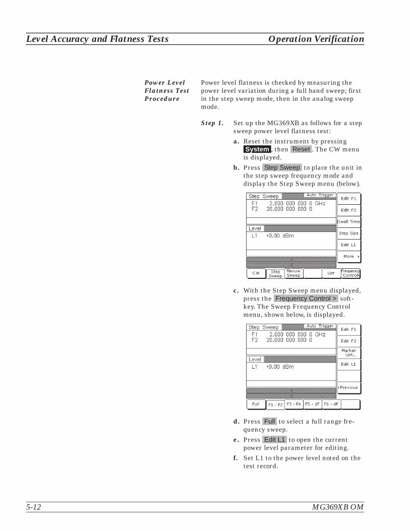
Power LevelFlatness TestProcedure
Power level flatness is checked by measuring thepower level variation during a full band sweep; firstin the step sweep mode, then in the analog sweepmode.
Step 1. Set up the MG369XB as follows for a stepsweep power level flatness test:
a. Reset the instrument by pressingSystem , then Reset . The CW menu
is displayed.
b. Press Step Sweep to place the unit inthe step sweep frequency mode anddisplay the Step Sweep menu (below).
c. With the Step Sweep menu displayed,press the Frequency Control > soft-key. The Sweep Frequency Controlmenu, shown below, is displayed.
d. Press Full to select a full range fre-quency sweep.
e. Press Edit L1 to open the currentpower level parameter for editing.
f. Set L1 to the power level noted on thetest record.
5-12 MG369XB OM
Level Accuracy and Flatness Tests Operation Verification

g. Now, return to the Step Sweep menuby pressing the < Previous soft-key.
h. At the Step Sweep menu, pressDwell Time to open the dwell-time-
per-step parameter for editing.
i. Set the dwell time to 1 second.
NOTEMonitor the MG369XB's horizontaloutput on the oscilloscope to deter-mine sweep start and stop.
Step 2. As the MG369XB steps through the fullfrequency range, measure the maximumand minimum power meter readings andrecord the values on the test record. Ver-ify that the variation (difference betweenthe maximum and minimum readings)does not exceed the value noted on thetest record.
Operation Verification Level Accuracy and Flatness Tests
MG369XB OM 5-13

Step 3. Set up the MG369XB as follows for an an-alog sweep power level flatness test:
a. Reset the instrument by pressingSYSTEM , then Reset . The CW menu
is displayed.
b. Press Analog Sweep to place theMG369XB in the analog sweep fre-quency mode and display the AnalogSweep menu (below).
c. With the Analog Sweep menu dis-played, press Frequency Control > .The Sweep Frequency Control menu(below) is displayed.
d. Press Full to select a full range fre-quency sweep.
e. Press Edit L1 to open the currentpower level parameter for editing.
f. Set L1 to the power level noted on thetest record.
g. Now, return to the Analog Sweepmenu by pressing < Previous .
h. At the Analog Sweep menu, press themenu soft-key Sweep Time to openthe sweep time parameter for editing.
5-14 MG369XB OM
Level Accuracy and Flatness Tests Operation Verification

i. Set the sweep time to 99 seconds.
NOTEMonitor the MG369XB’s horizontaloutput on the oscilloscope to deter-mine sweep start and stop.
Step 4. During the analog sweep, measure themaximum and minimum power meterreadings and record the values on the testrecord. Verify that the variation (differ-ence between the maximum and mini-mum readings) does not exceed the valuenoted on the test record.
Operation Verification Level Accuracy and Flatness Tests
MG369XB OM 5-15

5-16 MG369XB OM
Level Accuracy and Flatness Tests Operation Verification
Model MG3691B Serial No. ____________________ Date ___________
Standard Power Units with Options:__________________________________________________________________
Power Level Accuracy*(CW Frequency = 500 MHz)
Power Level Accuracy*(CW Frequency = 5.0 GHz)
SetPower
MeasuredPower
SetPower
MeasuredPower
+19 dBm
+18 dBm
+17 dBm
+16 dBm
+15 dBm
+14 dBm
+13 dBm
+12 dBm
+11 dBm
+10 dBm
+9 dBm
+8 dBm
+7 dBm
+6 dBm
+5 dBm
+4 dBm
+3 dBm
+2 dBm
+1 dBm
+0 dBm
–1 dBm
–2 dBm
–3 dBm
–4 dBm
–5 dBm
______dBm
______dBm
______dBm
______dBm
______dBm
______dBm
______dBm
______dBm
______dBm
______dBm
______dBm
______dBm
______dBm
______dBm
______dBm
______dBm
______dBm
______dBm
______dBm
______dBm
______dBm
______dBm
______dBm
______dBm
______dBm
* Specification: �1.0 dB * Specification: �1.0 dB
Table 5-3. Power Level Accuracy and Flatness Test Record (1 of 2)

Operation Verification Level Accuracy and Flatness Tests
MG369XB OM 5-17
Model MG3691B Serial No. ____________________ Date ___________
Standard Power Units with Options:__________________________________________________________________
Power Level Flatness (Step Sweep)
Set Power Max Power Min Power Variation **
+ 0 dBm _________dBm __________dBm _________dB
** Maximum variation is 2.2 dB
Power Level Flatness (Analog Sweep)
Set Power Max Power Min Power Variation ***
+ 0 dBm _________dBm __________dBm _________dB
*** Maximum variation is 5 dB (typical)
Table 5-3. Power Level Accuracy and Flatness Test Record (2 of 2)

5-18 MG369XB OM
Level Accuracy and Flatness Tests Operation Verification
Model MG3692B Serial No. ____________________ Date ___________
Standard Power Units with Options:__________________________________________________________________
Power Level Accuracy*(CW Frequency = 500 MHz)
Power Level Accuracy*(CW Frequency = 5.0 GHz)
Power Level Accuracy*(CW Frequency = 15.0 GHz)
SetPower
MeasuredPower
SetPower
MeasuredPower
SetPower
MeasuredPower
+19 dBm
+18 dBm
+17 dBm
+16 dBm
+15 dBm
+14 dBm
+13 dBm
+12 dBm
+11 dBm
+10 dBm
+9 dBm
+8 dBm
+7 dBm
+6 dBm
+5 dBm
+4 dBm
+3 dBm
+2 dBm
+1 dBm
+0 dBm
–1 dBm
–2 dBm
–3 dBm
–4 dBm
–5 dBm
______dBm
______dBm
______dBm
______dBm
______dBm
______dBm
______dBm
______dBm
______dBm
______dBm
______dBm
______dBm
______dBm
______dBm
______dBm
______dBm
______dBm
______dBm
______dBm
______dBm
______dBm
______dBm
______dBm
______dBm
______dBm
+17 dBm
+16 dBm
+15 dBm
+14 dBm
+13 dBm
+12 dBm
+11 dBm
+10 dBm
+9 dBm
+8 dBm
+7 dBm
+6 dBm
+5 dBm
+4 dBm
+3 dBm
+2 dBm
+1 dBm
+0 dBm
–1 dBm
–2 dBm
–3 dBm
–4 dBm
–5 dBm
______dBm
______dBm
______dBm
______dBm
______dBm
______dBm
______dBm
______dBm
______dBm
______dBm
______dBm
______dBm
______dBm
______dBm
______dBm
______dBm
______dBm
______dBm
______dBm
______dBm
______dBm
______dBm
______dBm
* Specification: �1.0 dB * Specification: �1.0 dB * Specification: �1.0 dB
Table 5-3. Power Level Accuracy and Flatness Test Record (1 of 2)
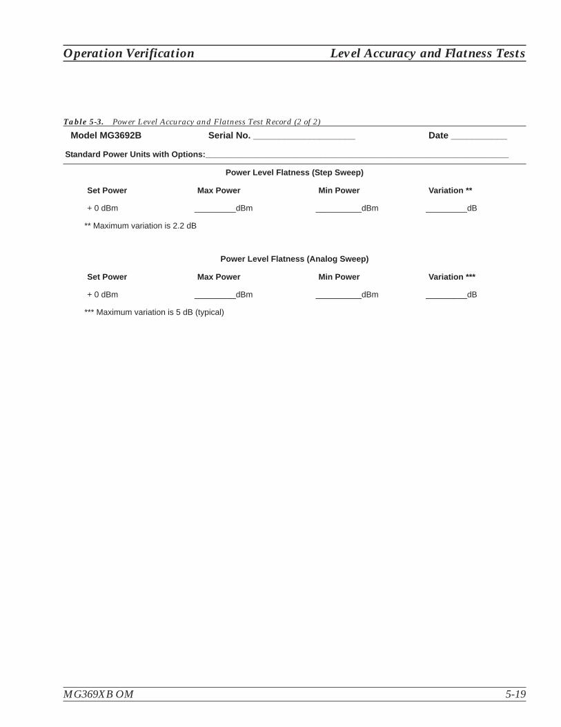
Operation Verification Level Accuracy and Flatness Tests
MG369XB OM 5-19
Model MG3692B Serial No. ____________________ Date ___________
Standard Power Units with Options:__________________________________________________________________
Power Level Flatness (Step Sweep)
Set Power Max Power Min Power Variation **
+ 0 dBm _________dBm __________dBm _________dB
** Maximum variation is 2.2 dB
Power Level Flatness (Analog Sweep)
Set Power Max Power Min Power Variation ***
+ 0 dBm _________dBm __________dBm _________dB
*** Maximum variation is 5 dB (typical)
Table 5-3. Power Level Accuracy and Flatness Test Record (2 of 2)

5-20 MG369XB OM
Level Accuracy and Flatness Tests Operation Verification
Model MG3693B Serial No. ____________________ Date ___________
Standard Power Units with Options:__________________________________________________________________
Power Level Accuracy*(CW Frequency = 500 MHz)
Power Level Accuracy*(CW Frequency = 5.0 GHz)
Power Level Accuracy*(CW Frequency = 15.0 GHz)
Power Level Accuracy*(CW Frequency = 25.0 GHz)
SetPower
MeasuredPower
SetPower
MeasuredPower
SetPower
MeasuredPower
SetPower
MeasuredPower
+15 dBm
+14 dBm
+13 dBm
+12 dBm
+11 dBm
+10 dBm
+9 dBm
+8 dBm
+7 dBm
+6 dBm
+5 dBm
+4 dBm
+3 dBm
+2 dBm
+1 dBm
+0 dBm
–1 dBm
–2 dBm
–3 dBm
–4 dBm
–5 dBm
______dBm
______dBm
______dBm
______dBm
______dBm
______dBm
______dBm
______dBm
______dBm
______dBm
______dBm
______dBm
______dBm
______dBm
______dBm
______dBm
______dBm
______dBm
______dBm
______dBm
______dBm
+12 dBm
+11 dBm
+10 dBm
+9 dBm
+8 dBm
+7 dBm
+6 dBm
+5 dBm
+4 dBm
+3 dBm
+2 dBm
+1 dBm
+0 dBm
–1 dBm
–2 dBm
–3 dBm
–4 dBm
–5 dBm
______dBm
______dBm
______dBm
______dBm
______dBm
______dBm
______dBm
______dBm
______dBm
______dBm
______dBm
______dBm
______dBm
______dBm
______dBm
______dBm
______dBm
______dBm
+6 dBm
+5 dBm
+4 dBm
+3 dBm
+2 dBm
+1 dBm
+0 dBm
–1 dBm
–2 dBm
–3 dBm
–4 dBm
–5 dBm
______dBm
______dBm
______dBm
______dBm
______dBm
______dBm
______dBm
______dBm
______dBm
______dBm
______dBm
______dBm
* Specification: �1.0 dB * Specification: �1.0 dB * Specification: �1.0 dB * Specification: �1.0 dB
Table 5-3. Power Level Accuracy and Flatness Test Record (1 of 2)

Operation Verification Level Accuracy and Flatness Tests
MG369XB OM 5-21
Model MG3693B Serial No. ____________________ Date ___________
Standard Power Units with Options:__________________________________________________________________
Power Level Flatness (Step Sweep)
Set Power Max Power Min Power Variation **
+ 0 dBm _________dBm __________dBm _________dB
** Maximum variation is 2.2 dB
Power Level Flatness (Analog Sweep)
Set Power Max Power Min Power Variation ***
+ 0 dBm _________dBm __________dBm _________dB
*** Maximum variation is 5 dB (typical)
Table 5-3. Power Level Accuracy and Flatness Test Record (2 of 2)

5-22 MG369XB OM
Level Accuracy and Flatness Tests Operation Verification
Model MG3694B Serial No. ____________________ Date ___________
Standard Power Units with Options:__________________________________________________________________
Power Level Accuracy*(CW Frequency = 500 MHz)
Power Level Accuracy*(CW Frequency = 5.0 GHz)
Power Level Accuracy*(CW Frequency = 15.0 GHz)
Power Level Accuracy*(CW Frequency = 25.0 GHz)
SetPower
MeasuredPower
SetPower
MeasuredPower
SetPower
MeasuredPower
SetPower
MeasuredPower
+15 dBm
+14 dBm
+13 dBm
+12 dBm
+11 dBm
+10 dBm
+9 dBm
+8 dBm
+7 dBm
+6 dBm
+5 dBm
+4 dBm
+3 dBm
+2 dBm
+1 dBm
+0 dBm
–1 dBm
–2 dBm
–3 dBm
–4 dBm
–5 dBm
______dBm
______dBm
______dBm
______dBm
______dBm
______dBm
______dBm
______dBm
______dBm
______dBm
______dBm
______dBm
______dBm
______dBm
______dBm
______dBm
______dBm
______dBm
______dBm
______dBm
______dBm
+15 dBm
+14 dBm
+13 dBm
+12 dBm
+11 dBm
+10 dBm
+9 dBm
+8 dBm
+7 dBm
+6 dBm
+5 dBm
+4 dBm
+3 dBm
+2 dBm
+1 dBm
+0 dBm
–1 dBm
–2 dBm
–3 dBm
–4 dBm
–5 dBm
______dBm
______dBm
______dBm
______dBm
______dBm
______dBm
______dBm
______dBm
______dBm
______dBm
______dBm
______dBm
______dBm
______dBm
______dBm
______dBm
______dBm
______dBm
______dBm
______dBm
______dBm
+12 dBm
+11 dBm
+10 dBm
+9 dBm
+8 dBm
+7 dBm
+6 dBm
+5 dBm
+4 dBm
+3 dBm
+2 dBm
+1 dBm
+0 dBm
–1 dBm
–2 dBm
–3 dBm
–4 dBm
–5 dBm
______dBm
______dBm
______dBm
______dBm
______dBm
______dBm
______dBm
______dBm
______dBm
______dBm
______dBm
______dBm
______dBm
______dBm
______dBm
______dBm
______dBm
______dBm
+6 dBm
+5 dBm
+4 dBm
+3 dBm
+2 dBm
+1 dBm
+0 dBm
–1 dBm
–2 dBm
–3 dBm
–4 dBm
–5 dBm
______dBm
______dBm
______dBm
______dBm
______dBm
______dBm
______dBm
______dBm
______dBm
______dBm
______dBm
______dBm
* Specification: �1.0 dB * Specification: �1.0 dB * Specification: �1.0 dB * Specification: �1.0 dB
Table 5-3. Power Level Accuracy and Flatness Test Record (1 of 2)

Operation Verification Level Accuracy and Flatness Tests
MG369XB OM 5-23
Model MG3694B Serial No. ____________________ Date ___________
Standard Power Units with Options:__________________________________________________________________
Power Level Flatness (Step Sweep)
Set Power Max Power Min Power Variation **
+ 0 dBm _________dBm __________dBm _________dB
** Maximum variation is 2.2 dB
Power Level Flatness (Analog Sweep)
Set Power Max Power Min Power Variation ***
+ 0 dBm _________dBm __________dBm _________dB
*** Maximum variation is 5 dB (typical)
Table 5-3. Power Level Accuracy and Flatness Test Record (2 of 2)
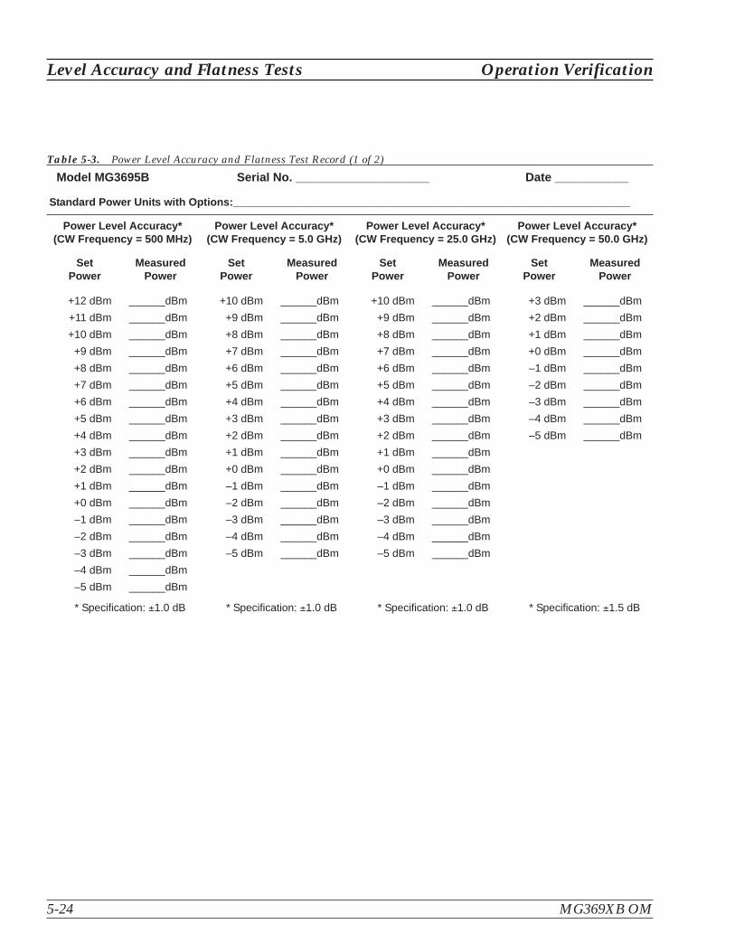
5-24 MG369XB OM
Level Accuracy and Flatness Tests Operation Verification
Model MG3695B Serial No. ____________________ Date ___________
Standard Power Units with Options:__________________________________________________________________
Power Level Accuracy*(CW Frequency = 500 MHz)
Power Level Accuracy*(CW Frequency = 5.0 GHz)
Power Level Accuracy*(CW Frequency = 25.0 GHz)
Power Level Accuracy*(CW Frequency = 50.0 GHz)
SetPower
MeasuredPower
SetPower
MeasuredPower
SetPower
MeasuredPower
SetPower
MeasuredPower
+12 dBm
+11 dBm
+10 dBm
+9 dBm
+8 dBm
+7 dBm
+6 dBm
+5 dBm
+4 dBm
+3 dBm
+2 dBm
+1 dBm
+0 dBm
–1 dBm
–2 dBm
–3 dBm
–4 dBm
–5 dBm
______dBm
______dBm
______dBm
______dBm
______dBm
______dBm
______dBm
______dBm
______dBm
______dBm
______dBm
______dBm
______dBm
______dBm
______dBm
______dBm
______dBm
______dBm
+10 dBm
+9 dBm
+8 dBm
+7 dBm
+6 dBm
+5 dBm
+4 dBm
+3 dBm
+2 dBm
+1 dBm
+0 dBm
–1 dBm
–2 dBm
–3 dBm
–4 dBm
–5 dBm
______dBm
______dBm
______dBm
______dBm
______dBm
______dBm
______dBm
______dBm
______dBm
______dBm
______dBm
______dBm
______dBm
______dBm
______dBm
______dBm
+10 dBm
+9 dBm
+8 dBm
+7 dBm
+6 dBm
+5 dBm
+4 dBm
+3 dBm
+2 dBm
+1 dBm
+0 dBm
–1 dBm
–2 dBm
–3 dBm
–4 dBm
–5 dBm
______dBm
______dBm
______dBm
______dBm
______dBm
______dBm
______dBm
______dBm
______dBm
______dBm
______dBm
______dBm
______dBm
______dBm
______dBm
______dBm
+3 dBm
+2 dBm
+1 dBm
+0 dBm
–1 dBm
–2 dBm
–3 dBm
–4 dBm
–5 dBm
______dBm
______dBm
______dBm
______dBm
______dBm
______dBm
______dBm
______dBm
______dBm
* Specification: �1.0 dB * Specification: �1.0 dB * Specification: �1.0 dB * Specification: �1.5 dB
Table 5-3. Power Level Accuracy and Flatness Test Record (1 of 2)

Operation Verification Level Accuracy and Flatness Tests
MG369XB OM 5-25
Model MG3695B Serial No. ____________________ Date ___________
Standard Power Units with Options:__________________________________________________________________
Power Level Flatness (Step Sweep)
Set Power Max Power Min Power Variation **
+ 0 dBm _________dBm __________dBm _________dB
** Maximum variation is 2.2 dB
Power Level Flatness (Analog Sweep)
Set Power Max Power Min Power Variation ***
+ 0 dBm _________dBm __________dBm _________dB
*** Maximum variation is 5 dB (typical)
Table 5-3. Power Level Accuracy and Flatness Test Record (2 of 2)

5-26 MG369XB OM
Level Accuracy and Flatness Tests Operation Verification
Model MG3696B Serial No. ____________________ Date ___________
Standard Power Units with Options:__________________________________________________________________
Power Level Accuracy*(CW Frequency = 500 MHz)
Power Level Accuracy*(CW Frequency = 5.0 GHz)
Power Level Accuracy*(CW Frequency = 25.0 GHz)
Power Level Accuracy*(CW Frequency = 50.0 GHz)
SetPower
MeasuredPower
SetPower
MeasuredPower
SetPower
MeasuredPower
SetPower
MeasuredPower
+12 dBm
+11 dBm
+10 dBm
+9 dBm
+8 dBm
+7 dBm
+6 dBm
+5 dBm
+4 dBm
+3 dBm
+2 dBm
+1 dBm
+0 dBm
–1 dBm
–2 dBm
–3 dBm
–4 dBm
–5 dBm
______dBm
______dBm
______dBm
______dBm
______dBm
______dBm
______dBm
______dBm
______dBm
______dBm
______dBm
______dBm
______dBm
______dBm
______dBm
______dBm
______dBm
______dBm
+10 dBm
+9 dBm
+8 dBm
+7 dBm
+6 dBm
+5 dBm
+4 dBm
+3 dBm
+2 dBm
+1 dBm
+0 dBm
–1 dBm
–2 dBm
–3 dBm
–4 dBm
–5 dBm
______dBm
______dBm
______dBm
______dBm
______dBm
______dBm
______dBm
______dBm
______dBm
______dBm
______dBm
______dBm
______dBm
______dBm
______dBm
______dBm
+10 dBm
+9 dBm
+8 dBm
+7 dBm
+6 dBm
+5 dBm
+4 dBm
+3 dBm
+2 dBm
+1 dBm
+0 dBm
–1 dBm
–2 dBm
–3 dBm
–4 dBm
–5 dBm
______dBm
______dBm
______dBm
______dBm
______dBm
______dBm
______dBm
______dBm
______dBm
______dBm
______dBm
______dBm
______dBm
______dBm
______dBm
______dBm
+3 dBm
+2 dBm
+1 dBm
+0 dBm
–1 dBm
–2 dBm
–3 dBm
–4 dBm
–5 dBm
______dBm
______dBm
______dBm
______dBm
______dBm
______dBm
______dBm
______dBm
______dBm
* Specification: �1.0 dB * Specification: �1.0 dB * Specification: �1.0 dB * Specification: �1.5 dB
Table 5-3. Power Level Accuracy and Flatness Test Record (1 of 2)

Operation Verification Level Accuracy and Flatness Tests
MG369XB OM 5-27
Model MG3696B Serial No. ____________________ Date ___________
Standard Power Units with Options:__________________________________________________________________
Power Level Flatness (Step Sweep)
Set Power Max Power Min Power Variation **
+ 0 dBm _________dBm __________dBm _________dB
** Maximum variation is 2.2 dB
Power Level Flatness (Analog Sweep)
Set Power Max Power Min Power Variation ***
+ 0 dBm _________dBm __________dBm _________dB
*** Maximum variation is 5 dB (typical)
Table 5-3. Power Level Accuracy and Flatness Test Record (2 of 2)

5-28 MG369XB OM
Level Accuracy and Flatness Tests Operation Verification
Model MG3691B Serial No. ____________________ Date ___________
High Power (Option 15) Units with Options:____________________________________________________________
Power Level Accuracy*(CW Frequency = 500 MHz)
Power Level Accuracy*(CW Frequency = 5.0 GHz)
SetPower
MeasuredPower
SetPower
MeasuredPower
+19 dBm
+18 dBm
+17 dBm
+16 dBm
+15 dBm
+14 dBm
+13 dBm
+12 dBm
+11 dBm
+10 dBm
+9 dBm
+8 dBm
+7 dBm
+6 dBm
+5 dBm
+4 dBm
+3 dBm
+2 dBm
+1 dBm
+0 dBm
–1 dBm
–2 dBm
–3 dBm
–4 dBm
–5 dBm
______dBm
______dBm
______dBm
______dBm
______dBm
______dBm
______dBm
______dBm
______dBm
______dBm
______dBm
______dBm
______dBm
______dBm
______dBm
______dBm
______dBm
______dBm
______dBm
______dBm
______dBm
______dBm
______dBm
______dBm
______dBm
+25 dBm
+24 dBm
+23 dBm
+22 dBm
+21 dBm
+20 dBm
+19 dBm
+18 dBm
+17 dBm
+16 dBm
+15 dBm
+14 dBm
+13 dBm
+12 dBm
+11 dBm
+10 dBm
+9 dBm
+8 dBm
+7 dBm
+6 dBm
+5 dBm
+4 dBm
+3 dBm
+2 dBm
+1 dBm
+0 dBm
–1 dBm
–2 dBm
–3 dBm
–4 dBm
–5 dBm
______dBm
______dBm
______dBm
______dBm
______dBm
______dBm
______dBm
______dBm
______dBm
______dBm
______dBm
______dBm
______dBm
______dBm
______dBm
______dBm
______dBm
______dBm
______dBm
______dBm
______dBm
______dBm
______dBm
______dBm
______dBm
______dBm
______dBm
______dBm
______dBm
______dBm
______dBm
* Specification: �1.0 dB * Specification: �1.0 dB
Table 5-3. Power Level Accuracy and Flatness Test Record (1 of 2)

Operation Verification Level Accuracy and Flatness Tests
MG369XB OM 5-29
Model MG3691B Serial No. ____________________ Date ___________
High Power (Option 15) Units with Options:____________________________________________________________
Power Level Flatness (Step Sweep)
Set Power Max Power Min Power Variation **
+ 0 dBm _________dBm __________dBm _________dB
** Maximum variation is 2.2 dB
Power Level Flatness (Analog Sweep)
Set Power Max Power Min Power Variation ***
+ 0 dBm _________dBm __________dBm _________dB
*** Maximum variation is 5 dB (typical)
Table 5-3. Power Level Accuracy and Flatness Test Record (2 of 2)
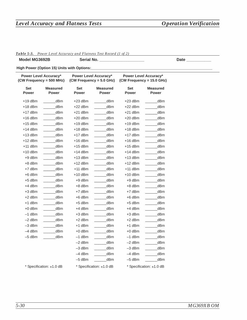
5-30 MG369XB OM
Level Accuracy and Flatness Tests Operation Verification
Model MG3692B Serial No. ____________________ Date ___________
High Power (Option 15) Units with Options:____________________________________________________________
Power Level Accuracy*(CW Frequency = 500 MHz)
Power Level Accuracy*(CW Frequency = 5.0 GHz)
Power Level Accuracy*(CW Frequency = 15.0 GHz)
SetPower
MeasuredPower
SetPower
MeasuredPower
SetPower
MeasuredPower
+19 dBm
+18 dBm
+17 dBm
+16 dBm
+15 dBm
+14 dBm
+13 dBm
+12 dBm
+11 dBm
+10 dBm
+9 dBm
+8 dBm
+7 dBm
+6 dBm
+5 dBm
+4 dBm
+3 dBm
+2 dBm
+1 dBm
+0 dBm
–1 dBm
–2 dBm
–3 dBm
–4 dBm
–5 dBm
______dBm
______dBm
______dBm
______dBm
______dBm
______dBm
______dBm
______dBm
______dBm
______dBm
______dBm
______dBm
______dBm
______dBm
______dBm
______dBm
______dBm
______dBm
______dBm
______dBm
______dBm
______dBm
______dBm
______dBm
______dBm
+23 dBm
+22 dBm
+21 dBm
+20 dBm
+19 dBm
+18 dBm
+17 dBm
+16 dBm
+15 dBm
+14 dBm
+13 dBm
+12 dBm
+11 dBm
+10 dBm
+9 dBm
+8 dBm
+7 dBm
+6 dBm
+5 dBm
+4 dBm
+3 dBm
+2 dBm
+1 dBm
+0 dBm
–1 dBm
–2 dBm
–3 dBm
–4 dBm
–5 dBm
______dBm
______dBm
______dBm
______dBm
______dBm
______dBm
______dBm
______dBm
______dBm
______dBm
______dBm
______dBm
______dBm
______dBm
______dBm
______dBm
______dBm
______dBm
______dBm
______dBm
______dBm
______dBm
______dBm
______dBm
______dBm
______dBm
______dBm
______dBm
______dBm
* Specification: �1.0 dB * Specification: �1.0 dB * Specification: �1.0 dB
Table 5-3. Power Level Accuracy and Flatness Test Record (1 of 2)

Operation Verification Level Accuracy and Flatness Tests
MG369XB OM 5-31
Model MG3692B Serial No. ____________________ Date ___________
High Power (Option 15) Units with Options:____________________________________________________________
Power Level Flatness (Step Sweep)
Set Power Max Power Min Power Variation **
+ 0 dBm _________dBm __________dBm _________dB
** Maximum variation is 2.2 dB
Power Level Flatness (Analog Sweep)
Set Power Max Power Min Power Variation ***
+ 0 dBm _________dBm __________dBm _________dB
*** Maximum variation is 5 dB (typical)
Table 5-3. Power Level Accuracy and Flatness Test Record (2 of 2)

5-32 MG369XB OM
Level Accuracy and Flatness Tests Operation Verification
Model MG3693B Serial No. ____________________ Date ___________
High Power (Option 15) Units with Options:____________________________________________________________
Power Level Accuracy*(CW Frequency = 500 MHz)
Power Level Accuracy*(CW Frequency = 5.0 GHz)
Power Level Accuracy*(CW Frequency = 15.0 GHz)
Power Level Accuracy*(CW Frequency = 25.0 GHz)
SetPower
MeasuredPower
SetPower
MeasuredPower
SetPower
MeasuredPower
SetPower
MeasuredPower
+17 dBm
+16 dBm
+15 dBm
+14 dBm
+13 dBm
+12 dBm
+11 dBm
+10 dBm
+9 dBm
+8 dBm
+7 dBm
+6 dBm
+5 dBm
+4 dBm
+3 dBm
+2 dBm
+1 dBm
+0 dBm
–1 dBm
–2 dBm
–3 dBm
–4 dBm
–5 dBm
______dBm
______dBm
______dBm
______dBm
______dBm
______dBm
______dBm
______dBm
______dBm
______dBm
______dBm
______dBm
______dBm
______dBm
______dBm
______dBm
______dBm
______dBm
______dBm
______dBm
______dBm
______dBm
______dBm
+23 dBm
+22 dBm
+21 dBm
+20 dBm
+19 dBm
+18 dBm
+17 dBm
+16 dBm
+15 dBm
+14 dBm
+13 dBm
+12 dBm
+11 dBm
+10 dBm
+9 dBm
+8 dBm
+7 dBm
+6 dBm
+5 dBm
+4 dBm
+3 dBm
+2 dBm
+1 dBm
+0 dBm
–1 dBm
–2 dBm
–3 dBm
–4 dBm
–5 dBm
______dBm
______dBm
______dBm
______dBm
______dBm
______dBm
______dBm
______dBm
______dBm
______dBm
______dBm
______dBm
______dBm
______dBm
______dBm
______dBm
______dBm
______dBm
______dBm
______dBm
______dBm
______dBm
______dBm
______dBm
______dBm
______dBm
______dBm
______dBm
______dBm
+19 dBm
+18 dBm
+17 dBm
+16 dBm
+15 dBm
+14 dBm
+13 dBm
+12 dBm
+11 dBm
+10 dBm
+9 dBm
+8 dBm
+7 dBm
+6 dBm
+5 dBm
+4 dBm
+3 dBm
+2 dBm
+1 dBm
+0 dBm
–1 dBm
–2 dBm
–3 dBm
–4 dBm
–5 dBm
______dBm
______dBm
______dBm
______dBm
______dBm
______dBm
______dBm
______dBm
______dBm
______dBm
______dBm
______dBm
______dBm
______dBm
______dBm
______dBm
______dBm
______dBm
______dBm
______dBm
______dBm
______dBm
______dBm
______dBm
______dBm
* Specification: �1.0 dB * Specification: �1.0 dB * Specification: �1.0 dB * Specification: �1.5 dB
Table 5-3. Power Level Accuracy and Flatness Test Record (1 of 2)

Operation Verification Level Accuracy and Flatness Tests
MG369XB OM 5-33
Model MG3693B Serial No. ____________________ Date ___________
High Power (Option 15) Units with Options:____________________________________________________________
Power Level Flatness (Step Sweep)
Set Power Max Power Min Power Variation **
+ 0 dBm _________dBm __________dBm _________dB
** Maximum variation is 2.2 dB
Power Level Flatness (Analog Sweep)
Set Power Max Power Min Power Variation ***
+ 0 dBm _________dBm __________dBm _________dB
*** Maximum variation is 5 dB (typical)
Table 5-3. Power Level Accuracy and Flatness Test Record (2 of 2)

5-34 MG369XB OM
Level Accuracy and Flatness Tests Operation Verification
Model MG3694B Serial No. ____________________ Date ___________
High Power (Option 15) Units with Options:____________________________________________________________
Power Level Accuracy*(CW Frequency = 500 MHz)
Power Level Accuracy*(CW Frequency = 5.0 GHz)
Power Level Accuracy*(CW Frequency = 15.0 GHz)
Power Level Accuracy*(CW Frequency = 25.0 GHz)
SetPower
MeasuredPower
SetPower
MeasuredPower
SetPower
MeasuredPower
SetPower
MeasuredPower
+17 dBm
+16 dBm
+15 dBm
+14 dBm
+13 dBm
+12 dBm
+11 dBm
+10 dBm
+9 dBm
+8 dBm
+7 dBm
+6 dBm
+5 dBm
+4 dBm
+3 dBm
+2 dBm
+1 dBm
+0 dBm
–1 dBm
–2 dBm
–3 dBm
–4 dBm
–5 dBm
______dBm
______dBm
______dBm
______dBm
______dBm
______dBm
______dBm
______dBm
______dBm
______dBm
______dBm
______dBm
______dBm
______dBm
______dBm
______dBm
______dBm
______dBm
______dBm
______dBm
______dBm
______dBm
______dBm
+23 dBm
+22 dBm
+21 dBm
+20 dBm
+19 dBm
+18 dBm
+17 dBm
+16 dBm
+15 dBm
+14 dBm
+13 dBm
+12 dBm
+11 dBm
+10 dBm
+9 dBm
+8 dBm
+7 dBm
+6 dBm
+5 dBm
+4 dBm
+3 dBm
+2 dBm
+1 dBm
+0 dBm
–1 dBm
–2 dBm
–3 dBm
–4 dBm
–5 dBm
______dBm
______dBm
______dBm
______dBm
______dBm
______dBm
______dBm
______dBm
______dBm
______dBm
______dBm
______dBm
______dBm
______dBm
______dBm
______dBm
______dBm
______dBm
______dBm
______dBm
______dBm
______dBm
______dBm
______dBm
______dBm
______dBm
______dBm
______dBm
______dBm
+23 dBm
+22 dBm
+21 dBm
+20 dBm
+19 dBm
+18 dBm
+17 dBm
+16 dBm
+15 dBm
+14 dBm
+13 dBm
+12 dBm
+11 dBm
+10 dBm
+9 dBm
+8 dBm
+7 dBm
+6 dBm
+5 dBm
+4 dBm
+3 dBm
+2 dBm
+1 dBm
+0 dBm
–1 dBm
–2 dBm
–3 dBm
–4 dBm
–5 dBm
______dBm
______dBm
______dBm
______dBm
______dBm
______dBm
______dBm
______dBm
______dBm
______dBm
______dBm
______dBm
______dBm
______dBm
______dBm
______dBm
______dBm
______dBm
______dBm
______dBm
______dBm
______dBm
______dBm
______dBm
______dBm
______dBm
______dBm
______dBm
______dBm
+19 dBm
+18 dBm
+17 dBm
+16 dBm
+15 dBm
+14 dBm
+13 dBm
+12 dBm
+11 dBm
+10 dBm
+9 dBm
+8 dBm
+7 dBm
+6 dBm
+5 dBm
+4 dBm
+3 dBm
+2 dBm
+1 dBm
+0 dBm
–1 dBm
–2 dBm
–3 dBm
–4 dBm
–5 dBm
______dBm
______dBm
______dBm
______dBm
______dBm
______dBm
______dBm
______dBm
______dBm
______dBm
______dBm
______dBm
______dBm
______dBm
______dBm
______dBm
______dBm
______dBm
______dBm
______dBm
______dBm
______dBm
______dBm
______dBm
______dBm
* Specification: �1.0 dB * Specification: �1.0 dB * Specification: �1.0 dB * Specification: �1.0 dB
Table 5-3. Power Level Accuracy and Flatness Test Record (1 of 2)

Operation Verification Level Accuracy and Flatness Tests
MG369XB OM 5-35
Model MG3694B Serial No. ____________________ Date ___________
High Power (Option 15) Units with Options:____________________________________________________________
Power Level Flatness (Step Sweep)
Set Power Max Power Min Power Variation **
+ 0 dBm _________dBm __________dBm _________dB
** Maximum variation is 2.2 dB
Power Level Flatness (Analog Sweep)
Set Power Max Power Min Power Variation ***
+ 0 dBm _________dBm __________dBm _________dB
*** Maximum variation is 5 dB (typical)
Table 5-3. Power Level Accuracy and Flatness Test Record (2 of 2)

5-36 MG369XB OM
Level Accuracy and Flatness Tests Operation Verification
Model MG3695B Serial No. ____________________ Date ___________
High Power (Option 15) Units with Options:____________________________________________________________
Power Level Accuracy*(CW Frequency = 500 MHz)
Power Level Accuracy*(CW Frequency = 5.0 GHz)
Power Level Accuracy*(CW Frequency = 25.0 GHz)
Power Level Accuracy*(CW Frequency = 50.0 GHz)
SetPower
MeasuredPower
SetPower
MeasuredPower
SetPower
MeasuredPower
SetPower
MeasuredPower
+16 dBm
+15 dBm
+14 dBm
+13 dBm
+12 dBm
+11 dBm
+10 dBm
+9 dBm
+8 dBm
+7 dBm
+6 dBm
+5 dBm
+4 dBm
+3 dBm
+2 dBm
+1 dBm
+0 dBm
–1 dBm
–2 dBm
–3 dBm
–4 dBm
–5 dBm
______dBm
______dBm
______dBm
______dBm
______dBm
______dBm
______dBm
______dBm
______dBm
______dBm
______dBm
______dBm
______dBm
______dBm
______dBm
______dBm
______dBm
______dBm
______dBm
______dBm
______dBm
______dBm
+23 dBm
+22 dBm
+21 dBm
+20 dBm
+19 dBm
+18 dBm
+17 dBm
+16 dBm
+15 dBm
+14 dBm
+13 dBm
+12 dBm
+11 dBm
+10 dBm
+9 dBm
+8 dBm
+7 dBm
+6 dBm
+5 dBm
+4 dBm
+3 dBm
+2 dBm
+1 dBm
+0 dBm
–1 dBm
–2 dBm
–3 dBm
–4 dBm
–5 dBm
______dBm
______dBm
______dBm
______dBm
______dBm
______dBm
______dBm
______dBm
______dBm
______dBm
______dBm
______dBm
______dBm
______dBm
______dBm
______dBm
______dBm
______dBm
______dBm
______dBm
______dBm
______dBm
______dBm
______dBm
______dBm
______dBm
______dBm
______dBm
______dBm
+19 dBm
+18 dBm
+17 dBm
+16 dBm
+15 dBm
+14 dBm
+13 dBm
+12 dBm
+11 dBm
+10 dBm
+9 dBm
+8 dBm
+7 dBm
+6 dBm
+5 dBm
+4 dBm
+3 dBm
+2 dBm
+1 dBm
+0 dBm
–1 dBm
–2 dBm
–3 dBm
–4 dBm
–5 dBm
______dBm
______dBm
______dBm
______dBm
______dBm
______dBm
______dBm
______dBm
______dBm
______dBm
______dBm
______dBm
______dBm
______dBm
______dBm
______dBm
______dBm
______dBm
______dBm
______dBm
______dBm
______dBm
______dBm
______dBm
______dBm
+13 dBm
+12 dBm
+11 dBm
+10 dBm
+9 dBm
+8 dBm
+7 dBm
+6 dBm
+5 dBm
+4 dBm
+3 dBm
+2 dBm
+1 dBm
+0 dBm
–1 dBm
–2 dBm
–3 dBm
–4 dBm
–5 dBm
______dBm
______dBm
______dBm
______dBm
______dBm
______dBm
______dBm
______dBm
______dBm
______dBm
______dBm
______dBm
______dBm
______dBm
______dBm
______dBm
______dBm
______dBm
______dBm
* Specification: �1.5 dB * Specification: �1.5 dB * Specification: �1.5 dB * Specification: �1.5 dB
Table 5-3. Power Level Accuracy and Flatness Test Record (1 of 2)

Operation Verification Level Accuracy and Flatness Tests
MG369XB OM 5-37
Model MG3695B Serial No. ____________________ Date ___________
High Power (Option 15) Units with Options:____________________________________________________________
Power Level Flatness (Step Sweep)
Set Power Max Power Min Power Variation **
+ 0 dBm _________dBm __________dBm _________dB
** Maximum variation is 2.2 dB
Power Level Flatness (Analog Sweep)
Set Power Max Power Min Power Variation ***
+ 0 dBm _________dBm __________dBm _________dB
*** Maximum variation is 5 dB (typical)
Table 5-3. Power Level Accuracy and Flatness Test Record (2 of 2)

5-38 MG369XB OM
Level Accuracy and Flatness Tests Operation Verification
Model MG3696B Serial No. ____________________ Date ___________
High Power (Option 15) Units with Options:____________________________________________________________
Power Level Accuracy*(CW Frequency = 500 MHz)
Power Level Accuracy*(CW Frequency = 5.0 GHz)
Power Level Accuracy*(CW Frequency = 25.0 GHz)
Power Level Accuracy*(CW Frequency = 50.0 GHz)
SetPower
MeasuredPower
SetPower
MeasuredPower
SetPower
MeasuredPower
SetPower
MeasuredPower
+16 dBm
+15 dBm
+14 dBm
+13 dBm
+12 dBm
+11 dBm
+10 dBm
+9 dBm
+8 dBm
+7 dBm
+6 dBm
+5 dBm
+4 dBm
+3 dBm
+2 dBm
+1 dBm
+0 dBm
–1 dBm
–2 dBm
–3 dBm
–4 dBm
–5 dBm
______dBm
______dBm
______dBm
______dBm
______dBm
______dBm
______dBm
______dBm
______dBm
______dBm
______dBm
______dBm
______dBm
______dBm
______dBm
______dBm
______dBm
______dBm
______dBm
______dBm
______dBm
______dBm
+21 dBm
+20 dBm
+19 dBm
+18 dBm
+17 dBm
+16 dBm
+15 dBm
+14 dBm
+13 dBm
+12 dBm
+11 dBm
+10 dBm
+9 dBm
+8 dBm
+7 dBm
+6 dBm
+5 dBm
+4 dBm
+3 dBm
+2 dBm
+1 dBm
+0 dBm
–1 dBm
–2 dBm
–3 dBm
–4 dBm
–5 dBm
______dBm
______dBm
______dBm
______dBm
______dBm
______dBm
______dBm
______dBm
______dBm
______dBm
______dBm
______dBm
______dBm
______dBm
______dBm
______dBm
______dBm
______dBm
______dBm
______dBm
______dBm
______dBm
______dBm
______dBm
______dBm
______dBm
______dBm
+19 dBm
+18 dBm
+17 dBm
+16 dBm
+15 dBm
+14 dBm
+13 dBm
+12 dBm
+11 dBm
+10 dBm
+9 dBm
+8 dBm
+7 dBm
+6 dBm
+5 dBm
+4 dBm
+3 dBm
+2 dBm
+1 dBm
+0 dBm
–1 dBm
–2 dBm
–3 dBm
–4 dBm
–5 dBm
______dBm
______dBm
______dBm
______dBm
______dBm
______dBm
______dBm
______dBm
______dBm
______dBm
______dBm
______dBm
______dBm
______dBm
______dBm
______dBm
______dBm
______dBm
______dBm
______dBm
______dBm
______dBm
______dBm
______dBm
______dBm
+9 dBm
+8 dBm
+7 dBm
+6 dBm
+5 dBm
+4 dBm
+3 dBm
+2 dBm
+1 dBm
+0 dBm
–1 dBm
–2 dBm
–3 dBm
–4 dBm
–5 dBm
______dBm
______dBm
______dBm
______dBm
______dBm
______dBm
______dBm
______dBm
______dBm
______dBm
______dBm
______dBm
______dBm
______dBm
______dBm
* Specification: �1.5 dB * Specification: �1.5 dB * Specification: �1.5 dB * Specification: �1.5 dB
Table 5-3. Power Level Accuracy and Flatness Test Record (1 of 2)

Operation Verification Level Accuracy and Flatness Tests
MG369XB OM 5-39/5-40
Model MG3696B Serial No. ____________________ Date ___________
High Power (Option 15) Units with Options:____________________________________________________________
Power Level Flatness (Step Sweep)
Set Power Max Power Min Power Variation **
+ 0 dBm _________dBm __________dBm _________dB
** Maximum variation is 2.2 dB
Power Level Flatness (Analog Sweep)
Set Power Max Power Min Power Variation ***
+ 0 dBm _________dBm __________dBm _________dB
*** Maximum variation is 5 dB (typical)
Table 5-3. Power Level Accuracy and Flatness Test Record (2 of 2)


Table of Contents
6-1 Introduction . . . . . . . . . . . . . . . . . . . . . . . . . . . . . . 6-3
6-2 Error and Warning/Status Messages . . . . . . . . . . . . . . . . . 6-3Self-Test Error Messages . . . . . . . . . . . . . . . . . . . 6-3Normal Operation Error and Warning/Status Messages . . . . 6-8
6-3 Troubleshooting . . . . . . . . . . . . . . . . . . . . . . . . . . . . 6-11
6-4 Routine Maintenance . . . . . . . . . . . . . . . . . . . . . . . . . 6-14Cleaning the Fan Filters. . . . . . . . . . . . . . . . . . . 6-14Cleaning the Data Display. . . . . . . . . . . . . . . . . . 6-14Replacing the Line Fuses . . . . . . . . . . . . . . . . . . 6-14
Chapter 6Operator Maintenance


Chapter 6Operator Maintenance
6-1 Introduction This chapter provides the information necessary for operator mainte-nance of the signal generator. Operator maintenance is limited to trou-bleshooting and repairs that can be made without removing theinstrument covers.
6-2 Error andWarning/StatusMessages
During normal operation, the MG369XB generates error messages toindicate internal malfunctions, abnormal signal generator operations,or invalid signal inputs or data entries. It also displays warning mes-sages to alert you of conditions that could result in inaccurate signalgenerator output. In addition, status messages are displayed to remindyou of current menu selections or settings.
Self-Test ErrorMessages
The MG369XB firmware includes internal diagnos-tics that self-test the instrument. These self-test di-agnostics perform a brief go/no-go test of most of theinstrument PCBs and other internal assemblies.
You can perform a signal generator self-test at anytime during normal operation by pressing Systemand then the System Menu soft-key Selftest .
If the signal generator fails self-test, an error mes-sage(s) is displayed on the front panel data display.These error messages describe the malfunction and,in most cases, provide an indication of what hasfailed. Table 6-1, pages 6-4 through 6-6, is a sum-mary listing of the self-test error messages. Includedfor each is a description of the probable cause(s),whether or not the MG369XB is still operable, and ifoperable, what operational degradation can be ex-pected.
MG369XB OM 6-3
During self-test with RF OUTPUT set to ON, the outputpower level is set to 0 dBm. Always disconnect sensitiveequipment from the unit before performing self-test.
CAUTION
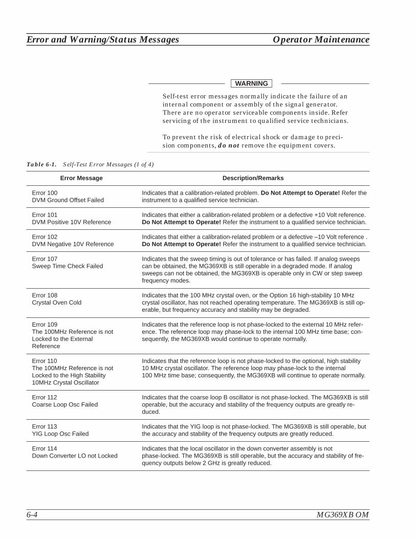
6-4 MG369XB OM
Error and Warning/Status Messages Operator Maintenance
Self-test error messages normally indicate the failure of aninternal component or assembly of the signal generator.There are no operator serviceable components inside. Referservicing of the instrument to qualified service technicians.
To prevent the risk of electrical shock or damage to preci-sion components, do not remove the equipment covers.
WARNING
Error Message Description/Remarks
Error 100DVM Ground Offset Failed
Indicates that a calibration-related problem. Do Not Attempt to Operate! Refer theinstrument to a qualified service technician.
Error 101DVM Positive 10V Reference
Indicates that either a calibration-related problem or a defective +10 Volt reference.Do Not Attempt to Operate! Refer the instrument to a qualified service technician.
Error 102DVM Negative 10V Reference
Indicates that either a calibration-related problem or a defective –10 Volt reference .Do Not Attempt to Operate! Refer the instrument to a qualified service technician.
Error 107Sweep Time Check Failed
Indicates that the sweep timing is out of tolerance or has failed. If analog sweepscan be obtained, the MG369XB is still operable in a degraded mode. If analogsweeps can not be obtained, the MG369XB is operable only in CW or step sweepfrequency modes.
Error 108Crystal Oven Cold
Indicates that the 100 MHz crystal oven, or the Option 16 high-stability 10 MHzcrystal oscillator, has not reached operating temperature. The MG369XB is still op-erable, but frequency accuracy and stability may be degraded.
Error 109The 100MHz Reference is notLocked to the ExternalReference
Indicates that the reference loop is not phase-locked to the external 10 MHz refer-ence. The reference loop may phase-lock to the internal 100 MHz time base; con-sequently, the MG369XB would continue to operate normally.
Error 110The 100MHz Reference is notLocked to the High Stability10MHz Crystal Oscillator
Indicates that the reference loop is not phase-locked to the optional, high stability10 MHz crystal oscillator. The reference loop may phase-lock to the internal100 MHz time base; consequently, the MG369XB will continue to operate normally.
Error 112Coarse Loop Osc Failed
Indicates that the coarse loop B oscillator is not phase-locked. The MG369XB is stilloperable, but the accuracy and stability of the frequency outputs are greatly re-duced.
Error 113YIG Loop Osc Failed
Indicates that the YIG loop is not phase-locked. The MG369XB is still operable, butthe accuracy and stability of the frequency outputs are greatly reduced.
Error 114Down Converter LO not Locked
Indicates that the local oscillator in the down converter assembly is notphase-locked. The MG369XB is still operable, but the accuracy and stability of fre-quency outputs below 2 GHz is greatly reduced.
Table 6-1. Self-Test Error Messages (1 of 4)

Operator Maintenance Error and Warning/Status Messages
MG369XB OM 6-5
Error Message Description/Remarks
Error 115Not Locked Indicator Failed
Indicates a failure of the phase-locked indicator circuit. The MG369XB is still opera-ble, but an error message will not appear on the data display when the output fre-quency is not phase-locked.
Error 116FM Loop Gain Check Failed
Indicates that the FM loop has failed or the loop gain is out of tolerance. TheMG369XB is still operable, but the frequency accuracy and stability are degraded.
Error 117Linearizer Check Failed
Indicates a failure of the linearizer DAC on the A5 PCB. The MG369XB is still oper-able, but the frequency accuracy of the RF output is degraded.
Error 118Switch point DAC Failed
Indicates a failure of the switch point DAC. The MG369XB is still operable, but willnot generate a CW Ramp.
Error 119Center Frequency CircuitsFailed
Indicates a failure of the center frequency circuitry. Do Not Attempt to Operate!Refer the instrument to a qualified service technician.
Error 120Delta-F Circuits Failed
Indicates a failure of the �F width DAC on the A5 PCB. The MG369XB will not gen-erate �F analog sweeps, but should produce �F step sweeps.
Error 121Unleveled Indicator Failed
Indicates a failure of the leveled detector circuitry. The MG369XB is still operable,but a warning message will not appear when the RF output is unleveled.
Error 122Level Reference Failed
Indicates a failure of the level reference circuitry. Use caution and always determinethe output power level when operating the MG369XB in this condition.
Error 123Detector Log Amp Failed
Indicates a failure of the level detector log amplifier circuitry. Use caution and al-ways determine the output power level when operating the MG369XB in this condi-tion.
Error 124Full Band Unlocked and Unleveled
Indicates a failure of both YIG-tuned oscillators. Do Not Attempt to Operate! Referthe instrument to a qualified service technician.
Error 1258.4 – 20 GHz Unlocked andUnleveled
Indicates a failure of the 8.4 to 20 GHz YIG-tuned oscillator. Do Not Attempt toOperate! Refer the instrument to a qualified service technician.
Error 1262 – 8.4 GHz Unlocked andUnleveled
Indicates a failure of the 2 to 8.4 GHz YIG-tuned oscillator. Do Not Attempt to Op-erate! Refer the instrument to a qualified service technician.
Error 127Detector Input CircuitFailed
Indicates a failure of the level detector input circuitry. Use caution and always deter-mine the output power level when operating the MG369XB in this condition.
Error 128.01 – 2 GHz Unleveled
Indicates a failure of the down converter leveling circuitry. The MG369XB operatesnormally but will have unleveled RF output in the 0.01 to 2 GHz frequency range.
Error 129Switched Filter or LevelDetector Failed
Indicates a failure of either the switched filter or level detector circuitry. TheMG369XB may not produce an RF output. Use caution and always determine theoutput power level when operating the MG369XB in this condition.
Table 6-1. Self-Test Error Messages (2 of 4)

6-6 MG369XB OM
Error and Warning/Status Messages Operator Maintenance
Error Message Description/Remarks
Error 1302 – 3.3 GH Switched Filter
Indicates a failure in the 2 to 3.3 GHz switched filter path within the switched filterassembly. The MG369XB may not produce an RF output in this frequency range.Use caution and always determine the output power level when operating theMG369XB in this condition.
Error 1313.3 – 5.5 GH Switched Filter
Indicates a failure in the 3.3 to 5.5 GHz switched filter path within the switched filterassembly. The MG369XB may not produce an RF output in this frequency range.Use caution and always determine the output power level when operating theMG369XB in this condition.
Error 1325.5 – 8.4 GH Switched Filter
Indicates a failure in the 5.5 to 8.4 GHz switched filter path within the switched filterassembly. The MG369XB may not produce an RF output in this frequency range.Use caution and always determine the output power level when operating theMG369XB in this condition.
Error 1338.4 – 13.25 GH Switched Filter
Indicates a failure in the 8.4 to 13.25 GHz switched filter path within the switched fil-ter assembly. The MG369XB may not produce an RF output in this frequencyrange. Use caution and always determine the output power level when operatingthe MG369XB in this condition.
Error 13413.25 – 20 GH Switched Filter
Indicates a failure in the 13.25 to 20 GHz switched filter path within the switched fil-ter assembly. The MG369XB may not produce an RF output in this frequencyrange. Use caution and always determine the output power level when operatingthe MG369XB in this condition.
Error 135Modulator or Driver Failed
Indicates a failure of the modulator in the switched filter assembly or the modulatordriver circuitry. The MG369XB may not produce an RF output. Use caution and al-ways determine the output power level when operating the MG369XB in this condi-tion.
Error 136SQM Unit or Driver Failed
Indicates a failure of the source quadrupler module (SQM) or SQM bias regulatorcircuitry. The MG369XB is still operable, but it may not produce an RF output in thefrequency range above 40 GHz.
Error 138SDM Unit or Driver Failed
Indicates a failure of the switched doubler module (SDM) or SDM bias regulator cir-cuitry. The MG369XB is still operable, but it may not produce an RF output in the 20to 40 GHz frequency range.
Error 13932 – 40 GHz SDM Section Failed
Indicates a failure in the 32 to 40 GHz switched doubler filter path within the SDM.The MG369XB is still operable, but it will not produce an RF output in the 32 to40 GHz frequency range.
Error 14025 – 32 GHz SDM Section Failed
Indicates a failure in the 25 to 32 GHz switched doubler filter path within the SDM.The MG369XB is still operable, but it will not produce an RF output in the 25 to32 GHz frequency range.
Error 14120 – 25 GHz SDM Section Failed
Indicates a failure in the 20 to 25 GHz switched doubler filter path within the SDM.The MG369XB is still operable, but it will not produce an RF output in the 20 to25 GHz frequency range.
Table 6-1. Self-Test Error Messages (3 of 4)

Operator Maintenance Error and Warning/Status Messages
MG369XB OM 6-7
Error Message Description/Remarks
Error 142Sample and Hold CircuitFailed
Indicates a failure of the sample and hold circuitry on the A6 PCB`. The MG369XBstill operates normally, but the RF output may be unleveled during pulse modula-tion.
Error 143Slope DAC Failed
Indicates a failure of the level slope DAC on the A6 PCB. The MG369XB still oper-ates normally, but RF output level flatness may be affected during frequencysweeps.
Error 144RF was Off when Self-teststarted. Some tests werenot performed.
Indicates that some self-tests were not performed because RF output was selectedOFF on the MG369XB front panel. Press the OUTPUT key to turn RF Output ONand run the instrument self-test again.
Error 145AM meter or associatedcircuitry failed
Indicates a failure of the internal AM circuitry and loss of the capability to provideamplitude modulation of the RF output signal using modulating signals from the in-ternal AM generator. The MG369XB may not provide amplitude modulation of theoutput signal using modulating signals from an external source.
Error 147Internal FM circuitry failed
Indicates a failure of the internal FM circuitry and loss of the capability to providefrequency modulation of the RF output signal using modulating signals from the in-ternal FM generator. The MG369XB may not provide frequency modulation of theoutput signal using modulating signals from an external source.
Error 148Pulse 100 MHz referencecircuitry failed
or
Error 148Pulse 40 MHz referencecircuitry failed
Indicates a failure of the pulse generator 100 MHz oscillator circuitry. The pulsegenerator may still function; however, the 100 MHz oscillator is not phase locked tothe 10 MHz reference time base. The pulse modulation function may not operate.
Indicates a failure of the pulse generator 40 MHz oscillator circuitry. The pulsegenerator may still function; however, the 40 MHz oscillator is not phase locked tothe 10 MHz reference time base. The pulse modulation function may not operate.
Table 6-1. Self-Test Error Messages (4 of 4)
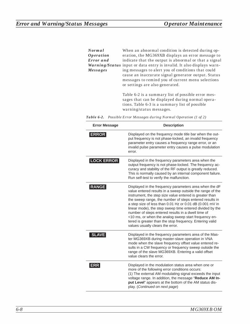
NormalOperationError andWarning/StatusMessages
When an abnormal condition is detected during op-eration, the MG369XB displays an error message toindicate that the output is abnormal or that a signalinput or data entry is invalid. It also displays warn-ing messages to alert you of conditions that couldcause an inaccurate signal generator output. Statusmessages to remind you of current menu selectionsor settings are also generated.
Table 6-2 is a summary list of possible error mes-sages that can be displayed during normal opera-tions. Table 6-3 is a summary list of possiblewarning/status messages.
6-8 MG369XB OM
Error and Warning/Status Messages Operator Maintenance
Error Message Description
ERROR Displayed on the frequency mode title bar when the out-put frequency is not phase-locked, an invalid frequencyparameter entry causes a frequency range error, or aninvalid pulse parameter entry causes a pulse modulationerror.
LOCK ERROR Displayed in the frequency parameters area when theoutput frequency is not phase-locked. The frequency ac-curacy and stability of the RF output is greatly reduced.This is normally caused by an internal component failure.Run self-test to verify the malfunction.
RANGE Displayed in the frequency parameters area when the dFvalue entered results in a sweep outside the range of theinstrument, the step size value entered is greater thanthe sweep range, the number of steps entered results ina step size of less than 0.01 Hz or 0.01 dB (0.001 mV inlinear mode), the step sweep time entered divided by thenumber of steps entered results in a dwell time of<10 ms, or when the analog sweep start frequency en-tered is greater than the stop frequency. Entering validvalues usually clears the error.
SLAVE Displayed in the frequency parameters area of the Mas-ter MG369XB during master-slave operation in VNAmode when the slave frequency offset value entered re-sults in a CW frequency or frequency sweep outside therange of the slave MG369XB. Entering a valid offsetvalue clears the error.
ERR Displayed in the modulation status area when one ormore of the following error conditions occurs:(1) The external AM modulating signal exceeds the inputvoltage range. In addition, the message “Reduce AM In-put Level” appears at the bottom of the AM status dis-play. (Continued on next page)
Table 6-2. Possible Error Messages during Normal Operation (1 of 2)

Operator Maintenance Error and Warning/Status Messages
MG369XB OM 6-9
Error Message Description
ERR Continued:(2) The external FM (or �M) modulating signal exceeds theinput voltage range. In addition, the message“Reduce FM (or �M) Input Level” appears at the bottom ofthe FM (or �M) status display.(3) A pulse parameter setting is invalid for the current pulsemodulation state, as follows:Pulse Period: <50 ns (100 MHz clock), <125 ns (40 MHz
clock), or <500 ns (10 MHz clock) longer than pulse widths+ delaysSingle Pulse Mode:Free Run or Gated Trigger:
Width1 > PRIDelayed Trigger:
Delay1 + Width1 > PRIDoublet Pulse Mode:Free Run Trigger:
Width1 > Delay2 orWidth1 + (Delay2 – Width1) + Width2 > PRI
Delayed Trigger:Width1 > Delay2 orDelay1 + Width1 + (Delay2 – Width1) +Width2 > PRI
External Trigger with or without Delay:Width1 > Delay2
Triplet Pulse Mode:Free Run Trigger:
Width1 > Delay2 or Width2 > Delay3 orWidth1 + (Delay2 – Width1) + Width2 +(Delay3 – Width2) + Width 3 > PRI
Delayed Trigger:Width1 > Delay2 or Width2 > Delay3 orDelay1 + Width1 + (Delay2 – Width1) + Width2 +(Delay3 – Width2) + Width 3 > PRI
External Trigger with or without Delay:Width1 > Delay2 or Width2 > Delay3
Quadruplet Pulse Mode:Free Run Trigger:
Width1 > Delay2 or Width2 > Delay3 orWidth3 > Delay4 orWidth1 + (Delay2 – Width1) + Width2 + (Delay3 –
Width2) + Width3 + (Delay4 – Width3) + Width4> PRI
Delayed Trigger:Width1 > Delay2 or Width2 > Delay3 orWidth3 > Delay4 orDelay1 + Width1 + (Delay2 – Width1) + Width2 +(Delay3 – Width2) + Width3 + (Delay4 – Width3) +Width4 > PRI
External Trigger with or without Delay:Width1 > Delay2 or Width2 > Delay3 orWidth3 > Delay4
Table 6-2. Possible Error Messages during Normal Operation (2 of 2)

6-10 MG369XB OM
Error and Warning/Status Messages Operator Maintenance
Warning/StatusMessage
Description
COLD This warning message indicates that the 100 MHzCrystal oven (or the 10 MHz Crystal oven if Option 16 isinstalled) has not reached operating temperature.Normally displayed during a cold start of the MG369XB.If the message is displayed during normal operation, itcould indicate a malfunction. Run self-test to verify.
UNLEVELED Displayed when the RF output goes unleveled.Normally caused by exceeding the specified lev-eled-power rating. Reducing the power level usuallyclears the warning message. If the warning message isdisplayed only when AM is selected ON, the modulatingsignal may be driving the RF output unleveled. Re-ducing the modulating signal or adjusting the powerlevel usually clears the warning.
UNLOCKED When Unlocked/Narrow FM or Unlocked/Wide FM isselected ON, this warning message appears indicatingthat the instrument is not phase-locked during this FMmode of operation.
REDUCE RATE This warning message is displayed when the AM rate,FM rate, or �M rate is set >100 kHz for a non-sinewave modulating waveform. Amplitude, frequency, orphase modulation of the output signal will continue butthe modulating waveform may be distorted.
SLOPE This status message indicates that a power slope cor-rection has been applied to the ALC.
EXTL REF This status message indicates that an external 10 MHzsignal is being used as the reference signal for theMG369XB.
OFFSET This status message indicates that a constant (offset)has been applied to the displayed power level.
CW RAMP This status message appears on all CW menu displaysto indicate that the CW ramp has been turned on.
USER 1...5 This status message indicates that a user level flatnesscorrection power-offset table has been applied to theALC.
Table 6-3. Possible Warning/Status Messages during Normal Operations

6-3 Troubleshooting Table 6-4 provides procedures for troubleshooting common malfunc-tions encountered during operation of the signal generator. Includedare procedures for troubleshooting faults that do not produce errormessages, such as, failure to power up and unexpected shutdown.
Operator Maintenance Troubleshooting
MG369XB OM 6-11
Signal Generator will not turn on(OPERATE light is OFF)
Normal Operation: When the MG369XB is connected to the powersource and the rear panel power switch turned on, the OPERATE lightshould illuminate and the instrument should power up.
Step 1. Disconnect the MG369XB from the power source, then checkthe line fuses on the rear panel.
� If a fuse is defective, replace (see page 6-15)
� If the fuses are good, go to the next step
Step 2. Check to see if power is available at the power receptacle.
� If not, move to a working receptacle
� If power is available, go to the next step
Step 3. Check the power cable
� If defective, replace
� If good, call a service technician
Signal Generator will not turn on(OPERATE light is ON)
Normal Operation: When the MG369XB is connected to the powersource and the rear panel power switch turned on, the OPERATE lightshould illuminate and the instrument should power up.
� If the OPERATE light illuminates but the unit fails topower up, the MG369XB has an internal component fail-ure. Call a service technician.
Table 6-4. Troubleshooting (1 of 3)

6-12 MG369XB OM
Troubleshooting Operator Maintenance
Signal Generator Quits During Operation(OPERATE light remains on)
Trouble Description: The signal generator operates for some time,then shuts down (OPERATE light remains on). After a short period, thesignal generator resumes normal operation. This is an indication thatthe MG369XB has reached an excessive operating temperature.
Step 1. Check that the fan is still operating during the time that theinstrument is shut down.
� If the fan is still operating, clean the air filter (seepage 6-14)
� If the fan is not operating, call a service technician
LOCK ERROR is Displayed
Trouble Description: This message is displayed in the frequency pa-rameters area to indicate that the output frequency is notphase-locked. It is normally caused by an internal component failure.
Step 1. Perform a self-test of the signal generator by pressing theSystem Menu soft-key Selftest.
� If self-test does not result in an error message(s), resumenormal operation
� If an error message(s) is displayed, call a service techni-cian
Table 6-4. Troubleshooting (2 of 3)

Operator Maintenance Troubleshooting
MG369XB OM 6-13
UNLEVELED is Displayed
Trouble Description: This message is displayed to indicate that theRF output is unleveled.
Step 1. Check that the output power does not exceed the specifiedleveled-power rating and that the RF OUTPUT connector isterminated into a 50� load.
� Reduce the power level to not exceed the specifiedleveled-power rating or terminate the RF OUTPUT con-nector with a 50� load
� If error message remains displayed, call a service techni-cian
RANGE is Displayed
Trouble Description: This message is displayed in the frequency pa-rameters area to indicate that (1) the analog sweep start frequency en-tered is greater than the stop frequency, (2) the dF value entered re-sults in a sweep outside the range of the instrument, (3) the step sizevalue entered is greater than the sweep range, (4) the number of stepsentered results in a step size of less than 0.1 Hz or 0.1 dB (0.001 mV),or (5) the step sweep time entered divided by the number of steps en-tered results in a dwell time of <10 ms.
Step 1. Check that (1) the analog sweep start frequency entered isnot greater than the stop frequency, (2) the dF value entereddoes not try to set the frequency sweep outside the range ofthe signal generator, (3) the step size entered is not greaterthan F2 minus F1, (4) the number of steps entered does notresult in a step size that is smaller than the resolution of theinstrument, or (5) the step sweep time and number of stepsdoes not result in a dwell time of <10 ms.
� Enter a valid sweep start frequency, dF value, step size,step sweep time, or number of steps
� If the error message remains displayed, call a servicetechnician
Table 6-4. Troubleshooting (3 of 3)

6-4 Routine Maintenance Routine maintenance that you can perform consists of cleaning the fanfilters, cleaning the data display, and replacing a defective line fuse(s).
Cleaning theFan Filters
The signal generator must always receive adequateventilation. A blocked fan filter can cause the in-strument to overheat and shut down. Check andclean the rear panel fan filters periodically. Cleanthe fan filters more frequently in dusty environ-ments. Clean the filters as follows:
Step 1. Disconnect the MG369XB from the powersource.
Step 2. Carefully vacuum the fan filters from theoutside to clean them.
Cleaning theData Display
The data display of the signal generator is protectedby a plastic display filter. To clean the display filter,use mild soap or detergent and water, or a commer-cial window cleaner. Do not use abrasive cleaners,tissues, or paper towels which can scratch the plas-tic surface.
Replacing theLine Fuses
The line fuses used in the MG369XB are 5A, type Tfuses. The line fuse value is printed on the rearpanel next to the power connector.
6-14 MG369XB OM
Routine Maintenance Operator Maintenance
Before changing the fuse, always remove the power cordfrom the power outlet. There is the risk of receiving a fatalelectric shock if the fuse is replaced with the power cordconnected.
Always use a new fuse of the type and rating specified bythe fuse markings on the rear panel of the instrument.
WARNING

To replace the line fuse, proceed as follows:
Step 1. Turn off the rear panel power switch anddisconnect the MG369XB from the powersource.
Step 2. Using a small flat-blade screwdriver,carefully pry under the tab next to therear panel power switch to open the coverand gain access to the fuse holders (referto Figure 6-1, below).
Step 3. Slide out the fuse holders.
Step 4. Replace the fuses in the fuse holders.
Step 5. Install the fuse holders in the rear panel.
Step 6. Close the cover to secure the fuse holdersin place. It will close with an audiblesnap.
Step 7. Reconnect the signal generator to thepower source and turn on the rear panelpower switch.
Operator Maintenance Routine Maintenance
MG369XB OM 6-15/6-16
Figure 6-1. Replacing the Line Fuse


Table of Contents
7-1 Introduction . . . . . . . . . . . . . . . . . . . . . . . . . . . . . . 7-3
7-2 Master-Slave Operation . . . . . . . . . . . . . . . . . . . . . . . . 7-4Connecting the Instruments . . . . . . . . . . . . . . . . . 7-4Initiating Master-Slave Operation . . . . . . . . . . . . . . 7-5Master-Slave Operation. . . . . . . . . . . . . . . . . . . . 7-7Master-Slave Operation in VNA Mode . . . . . . . . . . . . 7-7Terminating Master-Slave Operation . . . . . . . . . . . . . 7-9
7-3 Use with a 56100A Scalar Network Analyzer . . . . . . . . . . . . 7-10Connecting the MG369XB to the 56100A . . . . . . . . . . 7-10
7-4 Use with a 8003 Scalar Network Analyzer . . . . . . . . . . . . . 7-11Connecting the MG369XB to the 8003 . . . . . . . . . . . . 7-11Setting Up the MG369XB . . . . . . . . . . . . . . . . . . 7-12Initiating 8003 SNA Operation . . . . . . . . . . . . . . . 7-13
7-5 Use with a HP8757D Scalar Network Analyzer. . . . . . . . . . . 7-15Connecting the MG369XB to a HP8757D . . . . . . . . . . 7-15Setting Up the MG369XB . . . . . . . . . . . . . . . . . . 7-16Initiating HP8757D SNA Operation . . . . . . . . . . . . . 7-18
7-6 IF Up-Conversion (Option 7) . . . . . . . . . . . . . . . . . . . . . 7-19MG369XB Mixer Setup . . . . . . . . . . . . . . . . . . . 7-20
7-7 mmWave Source Modules . . . . . . . . . . . . . . . . . . . . . . 7-21
Chapter 7Use With Other Instruments

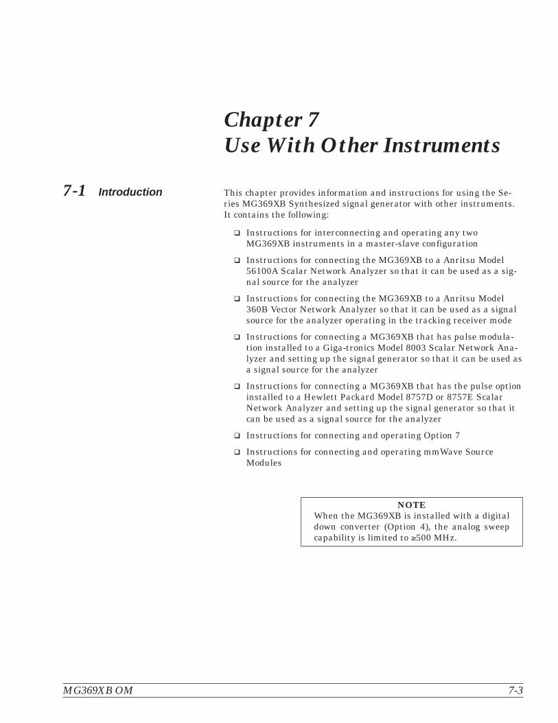
Chapter 7Use With Other Instruments
7-1 Introduction This chapter provides information and instructions for using the Se-ries MG369XB Synthesized signal generator with other instruments.It contains the following:
� Instructions for interconnecting and operating any twoMG369XB instruments in a master-slave configuration
� Instructions for connecting the MG369XB to a Anritsu Model56100A Scalar Network Analyzer so that it can be used as a sig-nal source for the analyzer
� Instructions for connecting the MG369XB to a Anritsu Model360B Vector Network Analyzer so that it can be used as a signalsource for the analyzer operating in the tracking receiver mode
� Instructions for connecting a MG369XB that has pulse modula-tion installed to a Giga-tronics Model 8003 Scalar Network Ana-lyzer and setting up the signal generator so that it can be used asa signal source for the analyzer
� Instructions for connecting a MG369XB that has the pulse optioninstalled to a Hewlett Packard Model 8757D or 8757E ScalarNetwork Analyzer and setting up the signal generator so that itcan be used as a signal source for the analyzer
� Instructions for connecting and operating Option 7
� Instructions for connecting and operating mmWave SourceModules
NOTEWhen the MG369XB is installed with a digitaldown converter (Option 4), the analog sweepcapability is limited to �500 MHz.
MG369XB OM 7-3

7-2 Master-SlaveOperation
Master-slave operation consists of connecting any two MG369XB in-struments together and configuring them so that they produce CWand synchronized, swept output signals at an operator-selectable fre-quency offset. One instrument (the Master) controls the other (theSlave) via interface cables between their rear panel AUX I/O and SE-RIAL I/O connectors. The two units are phase-locked together by con-necting them to the same 10 MHz reference time base.
ConnectingtheInstruments
Connect the two instruments, shown in Figure 7-1,as follows:
Step 1. Connect the 3-port AUX I/O cable end la-beled “MASTER” to the rear panel AUXI/O connector on the Master instrument.Connect the AUX I/O cable labeled“SLAVE” to the rear panel AUX I/O con-nector on the Slave instrument.
Step 2. Connect the ends of the flat interface ca-ble to the rear panel Serial I/O connectorson the Master and Slave instruments.
Step 3. Connect one end of a coaxial cable to therear panel 10 MHz REF OUT connector onthe Master instrument. Connect the otherend to the rear panel 10 MHz REF IN con-nector on the Slave instrument.
7-4 MG369XB OM
Master-Slave Operation Use With Other Instruments
� � � � � � � �
� � � � � � � � � � � � � � � � � � � � � ! �
# � � 3 # # � � 3 #
7 � � � : ?� � � � � 3 #
7 � � � : ?� � � � * 5
' 3 6* - �
' 3 6* - �
� � � � � � � �
! � � * ' �* - �
! � � * ' �* - �
# �� < 7 � � '! 5 '
Figure 7-1. MG369XB Configuration for Master-Slave Operation
NOTESWhen connecting two instrumentstogether for Master-Slave opera-tions, always use an Anritsu Mas-ter-Slave interface cable set, PartNo. ND36329.
If a Model 56100A Scalar NetworkAnalyzer is being used with themaster-slave configuration, (1) con-nect the AUX I/O cable end labeled“SNA” to the rear panel AUX I/Oconnector on the 56100A SNA and(2) connect a dedicated system buscable (P/N 2100-1) between theMaster instrument rear panelIEEE-488 GPIB connector and the56100A SNA rear panel DEDI-CATED GPIB connector.

Step 4. Connect the Master unit RF OUTPUT andthe Slave unit RF OUTPUT to the appro-priate connections on the DUT.
InitiatingMaster-SlaveOperation
The following paragraphs describe how to set upboth instruments to perform master-slave opera-tions. Use the CW Frequency Mode menu map (Fig-ure 4-2, page 4-6) to follow the menu sequences.
To initiate master-slave operation, turn on both in-struments and place them in CW mode. The CWmenu (below) is displayed.
On the Master unit, press Master Slave > to accessthe Master-Slave menu display (below).
This menu lets you perform the following:
� Access the Slave Frequencies List menu
� Set the delta frequency for the Slave unit
� Set the Slave unit's main power level (L1)
� Set the alternate sweep power level (L2) forthe Slave unit
� Turn master-slave operation on and off
Press Slave Freqs... to access the Slave FrequenciesList menu (following page).
Use With Other Instruments Master-Slave Operation
MG369XB OM 7-5
NOTEMaster-slave operations are alwaysinitiated in the CW frequencymode. Once initiated, you then canchange to a sweep frequency modeof operation by selecting the de-sired frequency mode on the Masterinstrument.

This menu lets you edit the listed frequencies forthe Slave instrument [SLF0-SLF, SLM0-SLM9].
Use the cursor control keys to select a frequency pa-rameter from the list, then press Edit Selected toedit its value. Edit the current frequency parametervalue using the cursor control keys, rotary dataknob, or enter a new value using the key pad andappropriate termination soft-key. Press Edit Se-lected again to close the open frequency parameter.
When you are finished editing the slave frequencies,press < Previous to return to the Master-Slavemenu (below).
The Master-Slave menu lets you set the delta fre-quency and L1 and L2 power level parameters forthe Slave unit.
Press Slave Delta Freq [SLDF] to open the dF fre-quency parameter.
Press Slave L1 [SLL1] to open the main power levelparameter.
Press Slave L2 [SLL2] to open the alternate sweeppower level parameter.
7-6 MG369XB OM
Master-Slave Operation Use With Other Instruments
NOTEUpon reset, the slave frequencies(F0 - F9 and M0 - M9) return to thedefault values.

Open the parameter you wish to change, then editthe current value using the cursor control keys, ro-tary data knob, or enter a new value using the keypad and appropriate termination soft-key. When youhave finished setting the open parameter, close it bypressing its menu soft-key or by making anothermenu selection.
Press Enable [S1] to begin master-slave operation.
Press < Previous to return to the CW menu.
Master-SlaveOperation
During master-slave operation, the Slave unit is inremote mode under the direct control of the Masterunit. The Slave unit displays the following:
� Its output CW frequency or sweep frequencyrange
� Its output power level
� The messages Remote and Local Lockout
The CW/sweep frequency settings on the Masterunit define the master sweep, and the correspondingfrequency settings on the Slave unit define the slavesweep. For example, if slave frequency F1 is set to4 GHz and slave frequency F2 is set to 12 GHz, thenthe Slave unit will sweep from 4 to 12 GHz when-ever the F1-F2 sweep range is selected on the Mas-ter unit. The Master unit will sweep from F1-F2with the values of F1 and F2 defined in the Masterunit's frequency list.
Master-SlaveOperation inVNA Mode
In the VNA mode of master-slave operation, a Slaveunit is coupled to a Master instrument that is con-nected to a Vector Network Analyzer in a source ordual source configuration. (Operating instructionsfor the vector network analyzer can be found in theVNA Operation Manual, P/N 10410-00110.) The fol-lowing paragraphs describe how to set up theMG369XB to perform master-slave operations in theVNA mode.
Use With Other Instruments Master-Slave Operation
MG369XB OM 7-7
NOTEThe 56100A SNA, when being usedwith the master-slave configura-tion, will not display markers.

Place both instruments in CW mode. Then, on theMaster unit, press Master Slave > to access theMaster Slave menu display.
At the Master Slave menu, press Slave Freqs... toaccess the Slave Frequencies List menu display (be-low).
Press VNA > to access the VNA menu display (be-low).
This menu lets you set the frequency offset and out-put power level for the Slave instrument in the VNAmode.
Press VNA Offset to open the slave frequency offsetparameter.
Press VNA Level to open the slave output powerlevel parameter.
Open the parameter you wish to change, then editthe current value using the cursor control keys, ro-tary data knob, or enter a new value using the keypad and appropriate termination key. When youhave finished setting the open parameter, close it bypressing its menu soft-key or by making anothermenu selection.
7-8 MG369XB OM
Master-Slave Operation Use With Other Instruments
Press < Previous to return to the Slave FrequenciesList menu.
Return to the Master-Slave menu and press Enableto begin master-slave operation.
TerminatingMaster-SlaveOperation
The following describes how to terminate mas-ter-slave operation and return the Slave instrumentto local (front panel) control.
On the Master instrument, select CW mode.
At the CW menu, press Master Slave > to accessthe Master-Slave menu display.
At the Master-Slave menu display, press Enable .This terminates master-slave operation and returnsthe Slave instrument to local (front panel) control.
Use With Other Instruments Master-Slave Operation
MG369XB OM 7-9
SLAVE
During master-slave operations inVNA mode, this error message isdisplayed on the Masterinstrument whenever the slave off-set value entered results in a CWfrequency or frequency sweep out-side the range of the Slave unit. En-tering a valid offset value clears theerror.

7-3 Use with a 56100AScalar NetworkAnalyzer
The MG369XB is directly compatible with the Anritsu Model 56100AScalar Network Analyzer (SNA). The following paragraphs provide in-structions for connecting the signal generator to the 56100A SNA sothat is can be used as a signal source for the analyzer. Operating in-structions for the network analyzer can be found in the Model 56100AScalar Network Analyzer Operation Manual, P/N 10410-00193.
Connectingthe MG369XBto the 56100A
Connect the MG369XB signal generator to the56100A SNA as shown in Figure 7-2.
Step 1. Connect one end of the Auxiliary I/O ca-ble (P/N 806-7) to the 56100A rear panelAUX I/O connector. Connect the other endof the cable to the MG369XB rear panelAUX I/O connector.
Step 2. Connect one end of the dedicated systembus cable (P/N 2100-1) to the 56100A rearpanel DEDICATED GPIB connector. Con-nect the other end of the cable to theMG369XB rear panel IEEE-488 GPIB con-nector.
Step 3. Turn on the instrument and the 56100A.The system is now ready to operate.
7-10 MG369XB OM
Use with a 56100A Scalar Network Analyzer Use With Other Instruments
� < 7 � � ' � ! � � � � 5 � � / � � . � ' � � � ? � �
� � ; < G 6 $ � ! � , � � � � � � � � � � �
' 3 6 � * - �
' 3 6 � * - �
* � � � � E � � � % * $
3 #
� � � � � � �
� � � � � � � � � % * $
! + �' 3 # � # � ! # � �
H
H
' $
Figure 7-2. MG369XB to 56100A SNA Connections
NOTESThe MG369XB’s GPIB addressshould be set to 5 (the default ad-dress setting) for operation with a56100A SNA. To verify or changethe GPIB address setting refer toConfiguring the GPIB on page 3-81.
The 56100A SNA will only acceptand display nine video markers, F1thru F9, from the MG369XB.
When performing amplifier testingonly use the MG369XB powerlevel, L1.

7-4 Use with a 8003Scalar NetworkAnalyzer
The MG369XB signal generator is compatible with the Giga-tronicsModel 8003 Scalar Network Analyzer (SNA). The following para-graphs provide instructions for connecting the MG369XB to the 8003SNA and setting up the signal generator so that it can operate as asignal source for the analyzer. Operating instructions for the scalarnetwork analyzer can be found in the Giga-tronics Model 8003 ScalarNetwork Analyzer Operation Manual.
Connectingthe MG369XBto the 8003
Connect the MG369XB signal generator to the 8003scalar network analyzer as shown in Figure 7-3.
Step 1. Connect one end of a GPIB cable to theMG369XB rear panel IEEE-488 GPIB con-nector. Connect the other end of the cableto the 8003 rear panel GPIB/ PRIVATEconnector.
Step 2. Connect the special AUX I/O interface ca-ble (Anritsu Part No. 806-90) to theMG369XB rear panel AUX I/O connector.Connect the cable end having BNC con-nectors as follows:
a. Connect the cable end labeled “SEQSYNC” to the 8003 rear panelBLANKING INPUT connector.
Use With Other Instruments Use with a 8003 Scalar Network Analyzer
MG369XB OM 7-11
� � � �� � � � � � � � � � � � � � �
" # # � � � � � � �$ � � � � � % � & � � � � ' � �
! � � � � �
� % * $ -% � * = ' # �
$ � ' 5 � * 5 � � * 5 % 3 #
' � � � � � � 3 #
! + � � % � * 5: � � * > � � 3 #
% 3 � ! � � # � * � � � � � * 5
! � I � ! 4 5 �
* � � � � E � �� % * $
�' $
# � � 3 #
# � � 3 #
' 3 6* - �
Figure 7-3. MG369XB to 8003 SNA Connections

b. Connect the cable end labeled “HORIZOUT” to the 8003 rear panel SWEEPIN connector.
Step 3. Connect one end of a coaxial cable havingBNC connectors to the MG369XB rearpanel PULSE TRIGGER IN connector.Connect the other end of the cable to the8003 rear panel AC MOD OUT connector.
Setting Up theMG369XB
The MG369XB must be in the 8003 Scalar GPIBmode of operation in order to operate as a signalsource for the SNA. The following paragraphs de-scribe how to set up the MG369XB to enable the8003 Scalar GPIB mode.
On the MG369XB front panel, press Line to placethe signal generator in operation.
Allow the signal generator to warm up, then pressthe System main menu key. At the System menudisplay, press Config . The System Configurationmenu (shown below) is displayed.
At the System Configuration menu, press GPIB > .The Configure GPIB menu (shown below) is dis-played.
7-12 MG369XB OM
Use with a 8003 Scalar Network Analyzer Use With Other Instruments

At the Configure GPIB menu, press More > to ac-cess the First Additional Configure GPIB menu (be-low).
At this menu, press Emulation > to access the Sec-ond Additional Configure GPIB menu (below).
Press 8003 Scalar to enable the 8003 Scalar GPIBmode. The display will reflect your selection.
The MG369XB signal generator is now ready to op-erate as a signal source for the 8003 SNA.
Initiating8003 SNAOperation
To initiate SNA operation, turn ON the Model 8003and calibrate a 8003 sensor(s). (Refer to the Model8003 Scalar Network Analyzer Operation Manualfor the calibration procedure.)
Use the following procedure to set the 8003 SourceAddress to “5”. (The default address is “6”.)
Step 1. On the 8003 front panel, press theCONFIG key.
Step 2. Select GPIB DEVICES from the menu dis-played on the CRT screen.
Use With Other Instruments Use with a 8003 Scalar Network Analyzer
MG369XB OM 7-13

Step 3. Select SOURCE, then SOURCE AD-DRESS.
Step 4. Enter 5 on the keypad, then press thedB/GHz termination key.
The 8003 will search for a source at address five(The default GPIB address of the series MG369XBsignal generators is five). When the 8003 has prop-erly identified the MG369XB, the message “Initial-izing W6700” will be displayed on the 8003 CRTscreen. (The MG369XB emulates the Anritsu 6700BSwept Frequency Synthesizer GPIB commandcodes.)
7-14 MG369XB OM
Use with a 8003 Scalar Network Analyzer Use With Other Instruments

7-5 Use with a HP8757DScalar NetworkAnalyzer
The MG369XB signal generator is compatible with the HewlettPackard Model 8757D Scalar Network Analyzer (SNA). The followingparagraphs provide instructions for connecting the MG369XB to theHP8757D SNA and setting up the signal generator so that it can oper-ate as a signal source for the analyzer. Operating instructions for thescalar network analyzer can be found in the Hewlett Packard 8757DScalar Network Analyzer Operation Manual.
Connectingthe MG369XBto a HP8757D
Connect the MG369XB signal generator to theHP8757D scalar network analyzer as shown in Fig-ure 7-4.
Step 1. Connect one end of a GPIB cable to theMG369XB rear panel IEEE-488 GPIB con-nector. Connect the other end to theHP8757D rear panel 8757 SYSTEM IN-TERFACE connector.
Step 2. Connect one end of a coaxial cable havingBNC connectors to the MG369XB rearpanel PULSE TRIGGER IN connector.Connect the other end of the cable to theHP8757D rear panel MODULATOR DRIVEconnector. (Required for ac mode detec-tion)
Use With Other Instruments Use with a HP8757D Scalar Network Analyzer
MG369XB OM 7-15
! + � � % � * 5 � � � � � 7 � =
' 3 6* - �
! � I � ! 4 5 �
! + % � + � � � � * 5 ! # � % � ! + � � %
�' $ �
� � � �� � � � � � � � � � � � � � �
( � " ) * ) + � � � � � � �$ � � � � � % � & � � � � ' � �
! � � � � �
� F � F! � � � � & � * � � � � � �
� � 3 � ' # � � � � * = �
% � ! � > � $ � ' 5 �
: � � * > � � 3 #
% 3 � ! � � # � * � � � � � * 5
* � � � � E � � �� % * $
# � � 3 #
# � � 3 #
Figure 7-4. MG369XB to HP8757D SNA Connections

Step 3. Connect the special AUX I/O interface ca-ble (Anritsu Part No. 806-97) to theMG369XB rear panel AUX I/O connector.Connect the cable end having BNC con-nectors as follows:
a. Connect the cable end labeled “SEQSYNC” to the HP8757D rear panelPOS Z BLANK connector.
b. Connect the cable end labeled “SWPDWELL IN” to the HP8757D rearpanel STOP SWEEP connector.
c. Connect the cable end labeled “HORIZOUT” to the HP8757D rear panelSWEEP IN 0 - 10V connector.
Setting Up theMG369XB
The MG369XB must be set to GPIB address 19 andin the 8757D Scalar mode of operation to operate asa signal source for the SNA. The following para-graphs describe how to set up the MG369XB to en-able the 8757D Scalar GPIB mode.
On the MG369XB front panel, press Line to placethe signal generator in operation.
Allow the signal generator to warm up, then pressthe System main menu key. At the System menudisplay, press Config . The System Configurationmenu (below) is displayed.
At the System Configuration menu, press GPIB .
7-16 MG369XB OM
Use with a HP8757D Scalar Network Analyzer Use With Other Instruments

The Configure GPIB menu (below) is displayed.
Press GPIB Address to change the address of theMG369XB on the bus. Enter 19 using the cursorcontrol keys or the data entry keypad and the termi-nator key
Hzns
ADRS
The new GPIB address (19) will appear on the dis-play.
Press More > to access the First Additional Config-ure GPIB menu (below).
At this menu, toggle the Display Updates betweenOn or Off depending upon your preference. Fastestmeasurement results are obtained when DisplayUpdates are Off.
Use With Other Instruments Use with a HP8757D Scalar Network Analyzer
MG369XB OM 7-17
NOTEFor the MG369XB, DisplayUpdates must be On when usingthe HP8757D emulation mode.
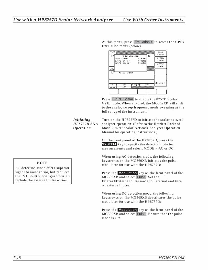
At this menu, press Emulation > to access the GPIBEmulation menu (below).
Press 8757D Scalar to enable the 8757D ScalarGPIB mode. When enabled, the MG369XB will shiftto the analog sweep frequency mode sweeping at thefull range of the instrument.
InitiatingHP8757D SNAOperation
Turn on the HP8757D to initiate the scalar networkanalyzer operation. (Refer to the Hewlett PackardModel 8757D Scalar Network Analyzer OperationManual for operating instructions.)
On the front panel of the HP8757D, press theSYSTEM key to specify the detector mode formeasurements and select: MODE = AC or DC.
When using AC detection mode, the followingkeystrokes on the MG369XB initiates the pulsemodulator for use with the HP8757D:
Press the Modulation key on the front panel of theMG369XB and select Pulse . Set theInternal/External pulse mode to External and turnon external pulse.
When using DC detection mode, the followingkeystrokes on the MG369XB deactivates the pulsemodulator for use with the HP8757D:
Press the Modulation key on the front panel of theMG369XB and select Pulse . Ensure that the pulsemode is Off.
7-18 MG369XB OM
Use with a HP8757D Scalar Network Analyzer Use With Other Instruments
NOTEAC detection mode offers superiorsignal to noise ratios, but requiresthe MG369XB configuration toinclude the external pulse option.

7-6 IF Up-Conversion(Option 7)
Option 7 adds an internal mixer that can be used for the genericup-conversion of an IF signal. The mixer’s RF, LO, and IF ports aremade available at the rear panel of the MG369XB via three femaleK-Connectors. The typical application will feed the MG369XB micro-wave output, which can be moved to the rear panel via Option 9K, tothe mixer’s LO port. The user’s external IF signal will be fed to themixer’s IF port. The new up-converted signal will be available at themixer’s RF port. Figure 7-5 shows a block diagram of a QPSK up-con-version using the MG369XB with an MG3681A QPSK source.
Use With Other Instruments IF Up-Conversion (Option 7)
MG369XB OM 7-19
MG3681A
QPSK Source
IF
LO RF
2-40 GHz
Up-converted QPSK
signal in transmission
channel.
MG369XB
RF Output
Figure 7-5. QPSK Up-conversion

MG369XBMixer Setup
Set up the MG369XB as follows:
Step 1. Connect the MG369XB RF output to theMG369XB rear panel LO input.
Step 2. Connect an IF source output to theMG369XB rear panel IF input.
Step 3. Set the MG369XB power level to+13 dBm.
Step 4. Set the desired up-conversion frequencyon the MG369XB.
Step 5. Connect the MG369XB rear panel mixerRF output to your transmission channel.
The MG369XB is now configured to up-convert theIF input to the microwave frequency set on the in-struments front panel display.
7-20 MG369XB OM
IF Up-Conversion (Option 7) Use With Other Instruments
AUX I/O10 MhzREF IN
HORIZOUT
PULSETRIG
IN
10 MhzREFOUT
EXTALCIN
SERIALI/O
IEEE-488 GPIB
IF
RF
LO
RF Output
AUX I/O
IEEE-488 GPIB
IF
RF
LO
RF Output
Figure 7-6. MG369XB Rear Panel IF Up-conversion Connectors.

7-7 mmWave SourceModules
When the MG369XB is configured with Option 18, mmW Bias Output,the synthesizer can power a mmWave source module to extend the RFfrequency output to 325 GHz.
Set up the mmWave source module and the MG369XB as shown inFigure 7-7 below:
When using mmWave source modules, the MG369XB should be set toa +10 dBm RF power level output. It is also recommended to configurea frequency scaling factor as indicated below:
Use With Other Instruments mmWave Source Modules
MG369XB OM 7-21
MG369XB
mmWaveSource Module
LO Input (+10 dBm)
DC Supply
MultipliedRF Output
Figure 7-7. MG369XB mmWave Source Module Setup.
mmWave Module Input Frequency Output Frequency Frequency Scaling Factor
WR-15 12.5 GHz to 18.8 GHz 50 GHz to 75 GHz 4
WR-12 10 GHz to 15 GHz 60 GHz to 90 GHz 6
WR-10 12.5 GHz to 18.4 GHz 75 GHz to 110 GHz 6
WR-8 7.5 GHz to 11.7 GHz 90 GHz to 140 GHz 8
WR-6 9.1 GHz to 14.2 GHz 110 GHz to 170 GHz 12
WR-5 11.6 GHz to 18.4 GHz 140 GHz to 220 GHz 12
WR-3 12.2 GHz to 18.1 GHz 220 GHz to 325 GHz 18
Table 7-1. MG369XB mmWave Source Module Setup.

To set the frequency scaling on the MG369XB, press:
System | Config RF > | More >
The Frequency Scaling factor can then be accessed by pressing theFrequency Scaling soft key.
NOTEFrequency scaling does not affect the actual fre-quency output of the MG369XB. It scales thedisplayed frequency on the MG369XB to matchthe output frequency of the mmWave sourcemodule.
7-22 MG369XB OM
mmWave Source Modules Use With Other Instruments

Appendix ARear Panel Connectors
A-1 Introduction This appendix provides descriptions for the rear panel connectors on atypical Series MG369XB Synthesized signal generator.
A-2 Rear PanelConnectors
Figure A-1 provides an illustration of the rear panel and describes therear panel connectors.
A-3 Connector Pin-outDiagrams
Figures A-2 and A-3 provide pin-out diagrams and descriptions for theAUX I/O and IEEE-488 GPIB multi-pin connectors on the rear panel.
MG369XB OM A-1

A-2 MG369XB OM
Rear Panel Index Rear Panel Connectors
AUX I/O 10 MHzREFIN
HORIZOUT
PULSETRIG
IN
10 MHzREFOUT
EXTALCIN
SERIALI/O
IEEE-488 GPIB
7 8 91 2 3 4 5 6
AUX I/O
IEEE-488 GPIB
IF
RF
LO
RF Output
PULSEVIDEOOUT
PULSESYNCOUT
FM/ M
OUT
�
AMOUT
AMIN
FM/ M
IN
�
10
1312
11
1514
20191817
IF
RF
LO
RF Output
AUX I/O 10 MHzREFIN
HORIZOUT
PULSETRIG
IN
10 MHzREFOUT
EXTALCIN
SERIALI/O
IEEE-488 GPIB
PULSEVIDEOOUT
PULSESYNCOUT
FM/ M
OUT
�
AMOUT
AMIN
FM/ M
IN
�
IF
RF
LO
RF Output
AUX I/O 10 MHzREFIN
HORIZOUT
PULSETRIG
IN
10 MHzREFOUT
EXTALCIN
SERIALI/O
IEEE-488 GPIB
PULSEVIDEOOUT
PULSESYNCOUT
FM/ M
OUT
�
AMOUT
AMIN
FM/ M
IN
�
Note: Connectors are Option Dependent
16
EFCIN
Figure A-1. Rear Panel, Series MG369XB Synthesized Signal Generator (1 of 3)

Rear Panel Connectors Rear Panel Index
MG369XB OM A-3
AUX I/O: 25-pin connector that provides for single cable interface with another MG369XB (master-slave
operation) or with other Anritsu instruments such as the Anritsu 56100A Scalar Network Analyzer. A
pin-out diagram for this connector is shown in Figure A-2.
AM OUT: Provides a video modulating signal from the internal AM generator. BNC connector.
HORIZ OUT: Provides a 0V to 10V ramp during all sweep modes, regardless of sweep width. In the CW
mode, provides a voltage between 0V and 10V proportional to the full frequency range of the instrument.
When the CW Ramp is enabled, connector provides a repetitive 0V to 10V ramp. BNC connector, 50�
impedance.
10 MHz REF IN: Accepts an external 10 MHz �100 Hz, 0 to 10 dBm time-base signal. Automatically dis-
connects the internal high-stability, time-base option, if installed. BNC connector, 50� impedance.
PULSE VIDEO OUT: Provides a video modulating signal from the internal pulse generator or external
pulse input. BNC connector.
PULSE TRIG IN: Accepts an external TTL level signal to pulse modulate the RF output. BNC connector.
10 MHz REF OUT: Provides a 0.5 Vp-p, AC coupled, 10 MHz signal derived from the internal frequency
standard of the signal generator. BNC connector, 50� impedance.
FM/�M IN: Accepts an external modulating signal (50�) to produce FM/�M on the RF output. FM/�M
sensitivity and FM/�M mode are selectable via the front panel menu or GPIB. BNC connector.
AM IN: Accepts an external modulating signal (50�) to produce AM on the RF output. AM sensitivity (Lin-
ear or Log) are selectable via the front panel menu or GPIB. BNC connector.
EXT ALC IN: Provides for leveling the RF output signal externally with either a remote detector or a
power meter. The rear panel BNC connector accepts a 0 to +1V or a 0 to –1V signal.
Input Line Voltage Module: Contains an input receptacle for connecting line voltage to the MG369XB,
two 5A, type T line fuses that provide over-voltage/current protection for the signal generator’s circuits
during operation and standby, and an On/Off power switch for applying line power to the MG369XB.
IEEE-488 GPIB: 24-pin connector that provides for remotely controlling the signal generator from an ex-
ternal controller via the IEEE488 bus (GPIB). A pin-out diagram for this connector is shown in Figure A-3.
FM/�M OUT: Provides a video modulating signal (50�) from the internal FM generator. BNC connector.
EFC: Electronic Frequency Control input accepts an external dc signal (–5V to +5V) to modulate the RF
output. Sensitivity: 10/n kHz/V where n is the reference multiplier (see page 3-80) and the modulation
bandwidth is �250 Hz. BNC connector.
PULSE SYNC OUT: Provides a TTL compatible signal synchronized to the internal pulse modulation out-
put. BNC connector.
Figure A-1. Rear Panel, Series MG369XB Synthesized Signal Generator (2 of 3)
8
9
7
6
5
1
2
3
4
10
11
12
13
14
15

A-4 MG369XB OM
Rear Panel Index Rear Panel Connectors
SERIAL I/O: Provides access to two RS-232 terminal ports to support service and calibration functions and
master-slave operations. RJ45 connector.
RF Output Connector (Option 9): Provides RF output at the rear panel of the instrument.
Mixer IF Input (Option 7): Accepts an external IF input from DC to 500 MHz or
Scan Modulator Input (Option 20): Accepts 0 to 6 Vdc modulating input.
Mixer RF Output (Option 7): Provides an up-converted IF signal from 1 to 40 GHz.
Mixer LO Input (Option 7): Accepts an external RF input from 1 to 40 GHz or
mmW Bias Output (Option 18): Provides a 12 Vdc supply for an external millimeter wave module.
Figure A-1. Rear Panel, Series MG369XB Synthesized Signal Generator (3 of 3)
17
18
19
20
16
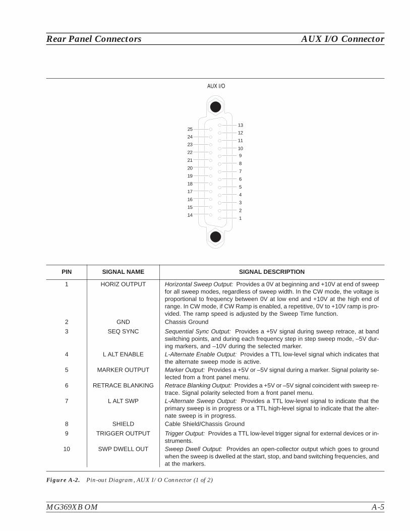
Rear Panel Connectors AUX I/O Connector
MG369XB OM A-5
PIN SIGNAL NAME SIGNAL DESCRIPTION
1 HORIZ OUTPUT Horizontal Sweep Output: Provides a 0V at beginning and +10V at end of sweepfor all sweep modes, regardless of sweep width. In the CW mode, the voltage isproportional to frequency between 0V at low end and +10V at the high end ofrange. In CW mode, if CW Ramp is enabled, a repetitive, 0V to +10V ramp is pro-vided. The ramp speed is adjusted by the Sweep Time function.
2 GND Chassis Ground
3 SEQ SYNC Sequential Sync Output: Provides a +5V signal during sweep retrace, at bandswitching points, and during each frequency step in step sweep mode, –5V dur-ing markers, and –10V during the selected marker.
4 L ALT ENABLE L-Alternate Enable Output: Provides a TTL low-level signal which indicates thatthe alternate sweep mode is active.
5 MARKER OUTPUT Marker Output: Provides a +5V or –5V signal during a marker. Signal polarity se-lected from a front panel menu.
6 RETRACE BLANKING Retrace Blanking Output: Provides a +5V or –5V signal coincident with sweep re-trace. Signal polarity selected from a front panel menu.
7 L ALT SWP L-Alternate Sweep Output: Provides a TTL low-level signal to indicate that theprimary sweep is in progress or a TTL high-level signal to indicate that the alter-nate sweep is in progress.
8 SHIELD Cable Shield/Chassis Ground
9 TRIGGER OUTPUT Trigger Output: Provides a TTL low-level trigger signal for external devices or in-struments.
10 SWP DWELL OUT Sweep Dwell Output: Provides an open-collector output which goes to groundwhen the sweep is dwelled at the start, stop, and band switching frequencies, andat the markers.
Figure A-2. Pin-out Diagram, AUX I/O Connector (1 of 2)
AUX I/O
14
15
16
17
18
19
20
21
22
23
24
1
2
3
4
5
6
7
8
9
10
11
12
1325

A-6 MG369XB OM
AUX I/O Connector Rear Panel Connectors
PIN SIGNAL NAME SIGNAL DESCRIPTION
11 LOCK STATUS Lock Status Output: Provides a TTL high-level signal when the frequency isphase-locked.
12 PENLIFT Penlift: Toggles to ground for plotter penlift control.
13 EXT TRIGGER External Trigger: Accepts a TTL low-level signal of 1 �s width to trigger a sweep.
14 V/GHz V/GHz Output: Provides a reference voltage relative to the RF output frequency(1.0 V/GHz for Model MG3692B; 0.5 V/GHz for Model MG3694B).
15 EOS INPUT End-of-Sweep Input: Accepts a TTL high-level signal to tell the signal generatorto begin the end of sweep dwell.
16 EOS OUTPUT End-of-Sweep Output: Provides a TTL high-level signal when the signal genera-tor has begun the end of sweep dwell.
17 AUX 1 Aux 1: Auxiliary input/output to the processor (PB6).
18 SWP DWELL IN Sweep Dwell Input: Permits a TTL low-level signal to pause the sweep. Thesweep resumes when the signal is removed.
19 AUX 2 Aux 2: Auxiliary input/output to the processor (PC3).
20 BAND SWITCH BLANK Band Switch Blanking Output: Provides a +5V or –5V signal coincident with bandswitching points. Signal polarity is selected from a front panel menu.
21 SPARE
22 HORIZ IN Horizontal Sweep Input: Accepts a 0V to 10V external sweep ramp from a MasterMG369XB. This input is automatically selected when the signal generator is in theSlave Mode.
23 RETURN Horizontal Sweep Input return.
24 GND Chassis Ground
25 MEMORY SEQ Memory Sequencing Input: Accepts a TTL low-level signal to sequence throughten stored, front panel setups.
Figure A-2. Pin-out Diagram, AUX I/O Connector (2 of 2)
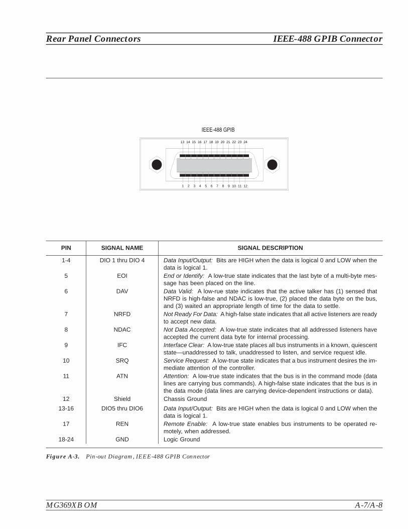
Rear Panel Connectors IEEE-488 GPIB Connector
MG369XB OM A-7/A-8
PIN SIGNAL NAME SIGNAL DESCRIPTION
1-4 DIO 1 thru DIO 4 Data Input/Output: Bits are HIGH when the data is logical 0 and LOW when thedata is logical 1.
5 EOI End or Identify: A low-true state indicates that the last byte of a multi-byte mes-sage has been placed on the line.
6 DAV Data Valid: A low-rue state indicates that the active talker has (1) sensed thatNRFD is high-false and NDAC is low-true, (2) placed the data byte on the bus,and (3) waited an appropriate length of time for the data to settle.
7 NRFD Not Ready For Data: A high-false state indicates that all active listeners are readyto accept new data.
8 NDAC Not Data Accepted: A low-true state indicates that all addressed listeners haveaccepted the current data byte for internal processing.
9 IFC Interface Clear: A low-true state places all bus instruments in a known, quiescentstate—unaddressed to talk, unaddressed to listen, and service request idle.
10 SRQ Service Request: A low-true state indicates that a bus instrument desires the im-mediate attention of the controller.
11 ATN Attention: A low-true state indicates that the bus is in the command mode (datalines are carrying bus commands). A high-false state indicates that the bus is inthe data mode (data lines are carrying device-dependent instructions or data).
12 Shield Chassis Ground
13-16 DIO5 thru DIO6 Data Input/Output: Bits are HIGH when the data is logical 0 and LOW when thedata is logical 1.
17 REN Remote Enable: A low-true state enables bus instruments to be operated re-motely, when addressed.
18-24 GND Logic Ground
Figure A-3. Pin-out Diagram, IEEE-488 GPIB Connector
IEEE-488 GPIB
13 14 15 16 17 18 19 20 21 22 23 24
1 2 3 4 5 6 7 8 9 10 11 12


Appendix BPerformance Specifications
This appendix includes the technical data sheet for the seriesMG3690B RF/Microwave Signal Generator, part number:11410-00344.
The latest copy of this data sheet may be downloaded from the AnritsuInternet site at: http://www.us.anritsu.com

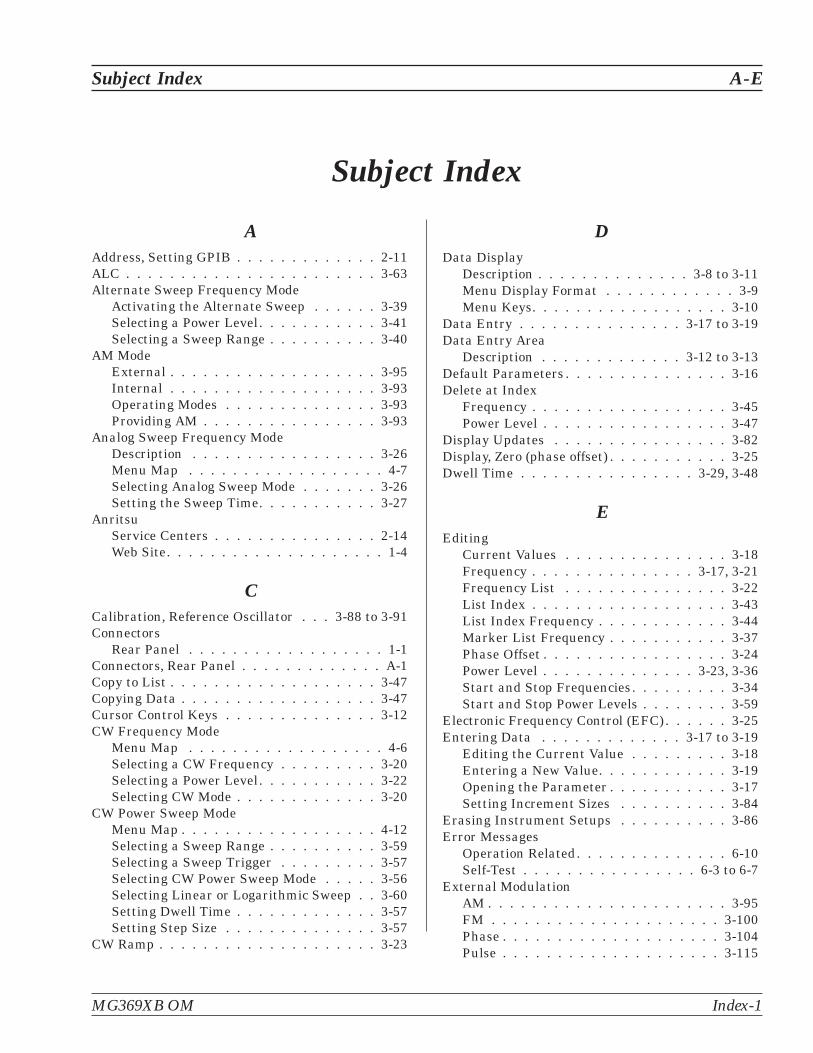
Subject Index
AAddress, Setting GPIB . . . . . . . . . . . . . 2-11ALC . . . . . . . . . . . . . . . . . . . . . . . 3-63Alternate Sweep Frequency Mode
Activating the Alternate Sweep . . . . . . 3-39Selecting a Power Level. . . . . . . . . . . 3-41Selecting a Sweep Range . . . . . . . . . . 3-40
AM ModeExternal . . . . . . . . . . . . . . . . . . . 3-95Internal . . . . . . . . . . . . . . . . . . . 3-93Operating Modes . . . . . . . . . . . . . . 3-93Providing AM . . . . . . . . . . . . . . . . 3-93
Analog Sweep Frequency ModeDescription . . . . . . . . . . . . . . . . . 3-26Menu Map . . . . . . . . . . . . . . . . . . 4-7Selecting Analog Sweep Mode . . . . . . . 3-26Setting the Sweep Time. . . . . . . . . . . 3-27
AnritsuService Centers . . . . . . . . . . . . . . . 2-14Web Site. . . . . . . . . . . . . . . . . . . . 1-4
CCalibration, Reference Oscillator . . . 3-88 to 3-91Connectors
Rear Panel . . . . . . . . . . . . . . . . . . 1-1Connectors, Rear Panel . . . . . . . . . . . . . A-1Copy to List . . . . . . . . . . . . . . . . . . . 3-47Copying Data . . . . . . . . . . . . . . . . . . 3-47Cursor Control Keys . . . . . . . . . . . . . . 3-12CW Frequency Mode
Menu Map . . . . . . . . . . . . . . . . . . 4-6Selecting a CW Frequency . . . . . . . . . 3-20Selecting a Power Level. . . . . . . . . . . 3-22Selecting CW Mode . . . . . . . . . . . . . 3-20
CW Power Sweep ModeMenu Map . . . . . . . . . . . . . . . . . . 4-12Selecting a Sweep Range . . . . . . . . . . 3-59Selecting a Sweep Trigger . . . . . . . . . 3-57Selecting CW Power Sweep Mode . . . . . 3-56Selecting Linear or Logarithmic Sweep . . 3-60Setting Dwell Time . . . . . . . . . . . . . 3-57Setting Step Size . . . . . . . . . . . . . . 3-57
CW Ramp . . . . . . . . . . . . . . . . . . . . 3-23
DData Display
Description . . . . . . . . . . . . . . 3-8 to 3-11Menu Display Format . . . . . . . . . . . . 3-9Menu Keys. . . . . . . . . . . . . . . . . . 3-10
Data Entry . . . . . . . . . . . . . . . 3-17 to 3-19Data Entry Area
Description . . . . . . . . . . . . . 3-12 to 3-13Default Parameters . . . . . . . . . . . . . . . 3-16Delete at Index
Frequency . . . . . . . . . . . . . . . . . . 3-45Power Level . . . . . . . . . . . . . . . . . 3-47
Display Updates . . . . . . . . . . . . . . . . 3-82Display, Zero (phase offset) . . . . . . . . . . . 3-25Dwell Time . . . . . . . . . . . . . . . . 3-29, 3-48
EEditing
Current Values . . . . . . . . . . . . . . . 3-18Frequency . . . . . . . . . . . . . . . 3-17, 3-21Frequency List . . . . . . . . . . . . . . . 3-22List Index . . . . . . . . . . . . . . . . . . 3-43List Index Frequency . . . . . . . . . . . . 3-44Marker List Frequency . . . . . . . . . . . 3-37Phase Offset . . . . . . . . . . . . . . . . . 3-24Power Level . . . . . . . . . . . . . . 3-23, 3-36Start and Stop Frequencies. . . . . . . . . 3-34Start and Stop Power Levels . . . . . . . . 3-59
Electronic Frequency Control (EFC) . . . . . . 3-25Entering Data . . . . . . . . . . . . . 3-17 to 3-19
Editing the Current Value . . . . . . . . . 3-18Entering a New Value. . . . . . . . . . . . 3-19Opening the Parameter . . . . . . . . . . . 3-17Setting Increment Sizes . . . . . . . . . . 3-84
Erasing Instrument Setups . . . . . . . . . . 3-86Error Messages
Operation Related. . . . . . . . . . . . . . 6-10Self-Test . . . . . . . . . . . . . . . . 6-3 to 6-7
External ModulationAM . . . . . . . . . . . . . . . . . . . . . . 3-95FM . . . . . . . . . . . . . . . . . . . . . 3-100Phase . . . . . . . . . . . . . . . . . . . . 3-104Pulse . . . . . . . . . . . . . . . . . . . . 3-115
Subject Index A-E
MG369XB OM Index-1

FFixed Power Level Mode
Menu Map . . . . . . . . . . . . . . . . . . 4-11Selecting a Power Level. . . . . . . . . . . 3-51Selecting Fixed Power Level Mode . . . . . 3-51Selecting Linear or Logarithmic Units. . . 3-52
Flatness Calibration . . . . . . . . . . . . . . 3-70FM Mode
External . . . . . . . . . . . . . . . . . . 3-100Internal . . . . . . . . . . . . . . . . . . . 3-98Operating Modes . . . . . . . . . . . . . . 3-96Providing FM . . . . . . . . . . . . . . . . 3-97
Frequency ControlFrequency List . . . . . . . . . . . . . . . 3-22Selecting a Preset Frequency . . . . . . . . 3-21Selecting a Preset Sweep Range . . . . . . 3-34Setting a Preset Sweep Range . . . . . . . 3-35
Frequency MarkersIntensity Markers . . . . . . . . . . . . . . 3-36Marker List . . . . . . . . . . . . . . . . . 3-37Video Markers. . . . . . . . . . . . . . . . 3-36
Frequency ModesAnalog Sweep Frequency Mode . . . . . . 3-26CW Frequency Mode . . . . . . . . . . . . 3-20List Sweep Frequency Mode . . . . . . . . 3-42Step Sweep Frequency Mode . . . . . . . . 3-28
Frequency Scaling . . . . . . . . . . . . . . . 3-80Frequency Synthesis Test
Test Procedure . . . . . . . . . . . . . . . . 5-5Test Setup. . . . . . . . . . . . . . . . . . . 5-5
Front PanelData Display Area . . . . . . . . 3-6, 3-8 to 3-11Data Entry Area . . . . . . . . 3-7, 3-12 to 3-13Layout . . . . . . . . . . . . . . . . . 3-6 to 3-7
Fuse, Replacing . . . . . . . . . . . . . . . . . 6-14
GGeneral Description . . . . . . . . . . . . . . . 1-3General Purpose Interface Bus (GPIB)
Address . . . . . . . . . . . . . . . . . . . 2-11Cable Length Restrictions . . . . . . . . . 2-10Interface Connector . . . . . . . . . . . . . 2-10Line Terminator . . . . . . . . . . . . . . . 2-12Native Interface Language . . . . . . . . . 2-12Setup and Interconnection . . . . . 2-10 to 2-12
IIdentification Number . . . . . . . . . . . . . . 1-3
IF Up-Conversion . . . . . . . . . . . . . . . . 7-19Index
Start . . . . . . . . . . . . . . . . . . . . . 3-48Stop . . . . . . . . . . . . . . . . . . . . . 3-48
Initial Inspection . . . . . . . . . . . . . . . . . 2-3Insert at Index
Frequency . . . . . . . . . . . . . . . . . . 3-45Power Level . . . . . . . . . . . . . . . . . 3-47
Inspection . . . . . . . . . . . . . . . . . . . . 2-3Intensity Markers . . . . . . . . . . . . . . . 3-36Internal Modulation
AM . . . . . . . . . . . . . . . . . . . . . . 3-93FM . . . . . . . . . . . . . . . . . . . . . . 3-98Phase . . . . . . . . . . . . . . . . . . . . 3-102Pulse . . . . . . . . . . . . . . . . . . . . 3-107
KKeypad . . . . . . . . . . . . . . . . . . . . . 3-13Knob, Rotary . . . . . . . . . . . . . . . . . . 3-13
LLanguage, GPIB . . . . . . . . . . . . . . . . 2-12Level Control . . . . . . . . . . . . . . . . . . 3-52Level Offset . . . . . . . . . . . . . . . . . . . 3-54Leveling Operations
ALC Power Slope . . . . . . . . . . . . . . 3-68Attenuator Decoupling . . . . . . . . . . . 3-67Auto Fixed Gain . . . . . . . . . . . . . . . 3-66External Leveling . . . . . . . . . . . . . . 3-65Fixed Gain . . . . . . . . . . . . . . . . . . 3-66Internal Leveling . . . . . . . . . . . . . . 3-64Menu Map . . . . . . . . . . . . . . . . . . 4-14Selecting a Leveling Mode . . . . . . . . . 3-63User Cal (User Power Level FlatnessCalibration) . . . . . . . . . . . . . . . . . 3-70
List Calculations . . . . . . . . . . . . . . . . 3-44List Sweep Frequency Mode
Description . . . . . . . . . . . . . . . . . 3-42List Frequency Editing . . . . . . . . . . . 3-45List Power Editing . . . . . . . . . . . . . 3-46Menu Map . . . . . . . . . . . . . . . . . . 4-10Selecting a Sweep Range . . . . . . . . . . 3-48Selecting a Sweep Trigger . . . . . . . . . 3-49Selecting List Sweep Mode . . . . . . . . . 3-43
Index-2 MG369XB OM
F-L Subject Index

List Sweep TriggerAuto . . . . . . . . . . . . . . . . . . . . . 3-49External . . . . . . . . . . . . . . . . 3-49, 3-57Manual . . . . . . . . . . . . . . . . . . . 3-49Single . . . . . . . . . . . . . . . . . 3-49, 3-57
Lock Error. . . . . . . . . . . . . . . . . . . . 6-12Log/Linear. . . . . . . . . . . . . . . . . . . . 3-31
MMain Menu Keys . . . . . . . . . . . . . . . . 3-11Maintenance, Routine
Display Cleaning . . . . . . . . . . . . . . 6-14Fan Filter Cleaning . . . . . . . . . . . . . 6-14
ManualElectronic . . . . . . . . . . . . . . . . . . . 1-4GPIB Programming . . . . . . . . . . . . . 1-4Maintenance . . . . . . . . . . . . . . . . . 1-4Related . . . . . . . . . . . . . . . . . . . . 1-4
Manual Sweep Frequency ModeDescription . . . . . . . . . . . . . . . . . 3-32Menu Map . . . . . . . . . . . . . . . . . . 4-9Selecting a Power Level. . . . . . . . . . . 3-36Selecting a Sweep Range . . . . . . . . . . 3-33Selecting Manual Sweep Mode . . . . . . . 3-33
Manual Sweep Mode . . . . . . . . . . . . . . 3-32Marker
Activating . . . . . . . . . . . . . . . . . . 3-38Editing List Frequency . . . . . . . . . . . 3-37Frequency . . . . . . . . . . . . . . . . . . 3-36Tagging List Frequency . . . . . . . . . . . 3-38
Master Reset . . . . . . . . . . . . . . . 3-75, 3-86Master-Slave Operation. . . . . . . . . . 7-4 to 7-9Menu Labels . . . . . . . . . . . . . . . . . . 3-10Menu Maps
Analog Sweep Frequency Mode . . . . . . . 4-7CW Frequency Mode . . . . . . . . . . . . . 4-6CW Power Sweep Mode . . . . . . . . . . . 4-12Description . . . . . . . . . . . . . . . . . . 4-3Fixed Power Level Mode . . . . . . . . . . 4-11Leveling Modes . . . . . . . . . . . . . . . 4-14List Sweep Frequency Mode . . . . . . . . 4-10Manual Sweep Frequency Mode . . . . . . . 4-9Sample Menu Map . . . . . . . . . . . . . . 4-5Step Sweep Frequency Mode. . . . . . . . . 4-8Sweep Frequency/Step Power Mode . . . . 4-13System Configuration . . . . . . . . . . . . 4-19
Menu Soft-Keys . . . . . . . . . . . . . . . . . 3-11
MessagesError . . . . . . . . . . . . . . . . . . 6-3 to 6-8Status . . . . . . . . . . . . . . . . . . . . . 6-8Warning . . . . . . . . . . . . . . . . . . . 6-10
Mixer, Internal . . . . . . . . . . . . . . . . . 7-20Mode
Frequency. . . . . . . . . . . . . . . . . . . 3-9Level . . . . . . . . . . . . . . . . . . . . . 3-9Modulation . . . . . . . . . . . . . . . . . . 3-9
Modulation Modes. . . . . . . . . . . 3-92 to 3-115Accessing . . . . . . . . . . . . . . . . . . 3-92Amplitude . . . . . . . . . . . . . . . . . . 3-93Frequency . . . . . . . . . . . . . . . . . . 3-96Phase . . . . . . . . . . . . . . . . . . . . 3-101Pulse . . . . . . . . . . . . . . . . . . . . 3-106Scan Modulation (Option 20) . . . . . . . 3-119
NNumber of Steps . . . . . . . . . . . . . . . . 3-30
OOperating Environment . . . . . . . . . . . . . 2-9Operational Verification Tests. . . . . . . . . . 5-3Operator Maintenance
Error and Warning/Status Messages 6-3 to 6-10Routine Maintenance . . . . . . . . 6-14 to 6-15Troubleshooting . . . . . . . . . . . 6-11 to 6-13
Options, List of . . . . . . . . . . . . . . 1-4 to 1-6
PParameter
Frequency. . . . . . . . . . . . . . . . . . . 3-9Modulation . . . . . . . . . . . . . . . . . . 3-9Power Level . . . . . . . . . . . . . . . . . . 3-9
Performance Specifications . . . . . . . . . 1-7, 1-1Phase Modulation Mode
External . . . . . . . . . . . . . . . . . . 3-104Internal. . . . . . . . . . . . . . . . . . . 3-102Operating Modes. . . . . . . . . . . . . . 3-101Providing Phase Modulation . . . . . . . 3-102
Phase Offset. . . . . . . . . . . . . . . . . . . 3-24Power Level Accuracy and Flatness Tests
Accuracy Test Procedure . . . . . . . . . . 5-11Flatness Test Procedure . . . . . . . . . . 5-12Test Records. . . . . . . . . . . . . 5-16 to 5-39Test Setup . . . . . . . . . . . . . . . . . . 5-10
Subject Index M-P
MG369XB OM Index-3

Power Level ControlAlternate Sweep. . . . . . . . . . . . . . . 3-41Level List . . . . . . . . . . . . . . . . . . 3-53Selecting a Preset Power Level . . . . . . . 3-52Selecting a Preset Sweep Range . . . . . . 3-60Setting a Preset Sweep Range . . . . . . . 3-60
Power Level ModesCW Power Sweep Mode . . . . . . . . . . . 3-56Fixed Power Level Mode . . . . . . 3-51 to 3-55Sweep Frequency/Step Power Mode . . . . 3-56
Power Level Offset . . . . . . . . . . . . . . . 3-54Power List . . . . . . . . . . . . . . . . . . . . 3-46Power Measurement, Internal (Option 8) . 3-116 to3-118Power Meter
Offset . . . . . . . . . . . . . . . . . . . . 3-74Scaling . . . . . . . . . . . . . . . . . . . . 3-74
Power Requirements . . . . . . . . . . . . . . . 2-8Power Sweep Mode . . . . . . . . . . . . . . . 3-56Power Sweep Trigger
Auto . . . . . . . . . . . . . . . . . . . . . 3-57Pre-Calc List . . . . . . . . . . . . . . . . . . 3-44Preparation for Storage/Shipment . . . . . . . 2-13Preparation for Use . . . . . . . . . . . . 2-3 to 2-4
Operating Environment . . . . . . . . . . . 2-9Power Requirements . . . . . . . . . . . . . 2-8Standby Operation . . . . . . . . . . . . . . 2-9Warmup Time. . . . . . . . . . . . . . . . . 2-9
Preset Frequencies . . . . . . . . . . . . . . . 3-21Preset Sweep Ranges . . . . . . . . . . . . . . 3-34Pulse Modulation Mode
External . . . . . . . . . . . . . . . . . . 3-115Internal. . . . . . . . . . . . . . . . . . . 3-107Operating Modes. . . . . . . . . . . . . . 3-106Providing Pulse Modulation. . . . . . . . 3-107Stepped Delay . . . . . . . . . . . . . . . 3-113
RRack Mounting Kit (Option 1)
Installation Procedures . . . . . . . . 2-5 to 2-9Range, Error . . . . . . . . . . . . . . . . . . 6-13Rear Panel Connectors . . . . . . . . . . . . . A-1Rear Panel Layout . . . . . . . . . . . . . . . . A-2Recalling Instrument Setups. . . . . . . . . . 3-86Recommended Test Equipment . . . . . . . . . 1-7Reference Oscillator Calibration. . . . 3-88 to 3-91Reset, Master . . . . . . . . . . . . . . . . . . 3-86Reset, to Default Parameters. . . . . . . . . . 3-15
SSafety
Caution . . . . . . . . . . . . . . . . . . . . 1-1Symbols . . . . . . . . . . . . . . . . . . . . 1-1Warning . . . . . . . . . . . . . . . . . . . . 1-1
Saving Instrument Setups . . . . . . . . . . . 3-85Scan Modulation (Option 20) . . . . . . . . . 3-119Scope of Manual . . . . . . . . . . . . . . . . . 1-3Secure Operation . . . . . . . . . . . . . . . . 3-87Self Test
From System Menu . . . . . . . . . . . . . 3-15Self-Test
Error Messages . . . . . . . . . . . . 6-3 to 6-7Shipment . . . . . . . . . . . . . . . . . . . . 2-13Specifications, Performance . . . . . . . . . . . 1-7Standby Operation . . . . . . . . . . . . . 2-9, 3-14Start Index . . . . . . . . . . . . . . . . . . . 3-48Start Up. . . . . . . . . . . . . . . . . 3-14 to 3-16Start-Up Display . . . . . . . . . . . . . . . . 3-14Step Size . . . . . . . . . . . . . . . . . . . . 3-29Step Sweep Frequency Mode
Description . . . . . . . . . . . . . . . . . 3-28Menu Map . . . . . . . . . . . . . . . . . . 4-8Selecting a Power Level. . . . . . . . . . . 3-36Selecting a Sweep Range . . . . . . . . . . 3-33Selecting a Sweep Trigger . . . . . . . . . 3-31Selecting Alternate Sweep . . . . . . . . . 3-38Selecting Log/Linear Sweep . . . . . . . . 3-31Selecting Step Sweep Mode. . . . . . . . . 3-28Setting Dwell Time . . . . . . . . . . . . . 3-29Setting Step Size . . . . . . . . . . . . . . 3-29Setting Sweep Time . . . . . . . . . . . . . 3-29Using Frequency Markers . . . . . . . . . 3-36
Stop Index. . . . . . . . . . . . . . . . . . . . 3-48Storage . . . . . . . . . . . . . . . . . . . . . 2-13Sweep Frequency Modes
List Sweep Frequency Mode . . . . . . . . 3-42Manual Sweep Frequency Mode . . . . . . 3-32Step Sweep Frequency Mode . . . . . . . . 3-28
Sweep Frequency Operation . . . . . . 3-26 to 3-50Sweep Frequency/Step Power Mode
Menu Map . . . . . . . . . . . . . . . . . . 4-13Selecting a Sweep Frequency/Step Power Mode. . . . . . . . . . . . . . . . . . . . . . . . 3-61Selecting a Sweep Range . . . . . . . . . . 3-59Selecting Linear or Logarithmic Sweep . . 3-60Setting Step Size . . . . . . . . . . . . . . 3-62
Sweep Time . . . . . . . . . . . . . . . . 3-27, 3-30
Index-4 MG369XB OM
R-S Subject Index

Sweep TriggerAuto . . . . . . . . . . . . . . . . . . . . . 3-31External . . . . . . . . . . . . . . . . . . . 3-31Single . . . . . . . . . . . . . . . . . . . . 3-31
System ConfigurationConfiguring the Front Panel . . . . . . . . 3-77Configuring the GPIB. . . . . . . . . . . . 3-81Configuring the Rear Panel. . . . . . . . . 3-78Configuring the RF . . . . . . . . . . . . . 3-79Frequency Scaling. . . . . . . . . . . . . . 3-80Menu Map . . . . . . . . . . . . . . . . . . 4-19Setting Increment Sizes . . . . . . . . . . 3-84
TTermination Soft-Keys . . . . . . . . . . . . . 3-13Termination, GPIB . . . . . . . . . . . . . . . 2-12Test Equipment . . . . . . . . . . . . . . . 1-7, 5-3Test Record
Frequency Synthesis . . . . . . . . . . . . . 5-7Testing, Operational Verification
Frequency Synthesis . . . . . . . . . 5-5 to 5-9Initial MG369XB Checkout . . . . . . . . . 5-4Power Level Accuracy and Flatness 5-10 to 5-39Test Equipment. . . . . . . . . . . . . . . . 5-3Test Records . . . . . . . . 5-4, 5-7, 5-16 to 5-39
Testing, Performance VerificationMaximum Leveled Power Listing. . . 1-5 to 1-6
Title Bar . . . . . . . . . . . . . . . . . . . . . 3-9
TriggerList Sweep . . . . . . . . . . . . . . . . . . 3-49Power Sweep . . . . . . . . . . . . . . . . 3-57Sweep . . . . . . . . . . . . . . . . . . . . 3-31
Troubleshooting Tables. . . . . . . . . 6-11 to 6-13
UUnits . . . . . . . . . . . . . . . . . . . 3-52, 3-60Unleveled . . . . . . . . . . . . . . . . . . . . 6-13Updates, Display . . . . . . . . . . . . . . . . 3-82Use With Other Instruments
56100A Scalar Network Analyzer . . . . . 7-108003 Scalar Network Analyzer . . 7-11 to 7-14HP8757D Scalar Network Analyzer 7-15 to 7-18IF Up-Conversion . . . . . . . . . . 7-19 to 7-20Master-Slave Operation . . . . . . . . 7-4 to 7-9Option 7 . . . . . . . . . . . . . . . . . . . 7-19
VVideo Markers . . . . . . . . . . . . . . . . . 3-36
WWarmup Time . . . . . . . . . . . . . . . . . . 2-9
ZZero Display (phase offset) . . . . . . . . . . . 3-25
Subject Index T-Z
MG369XB OM Index-5/Index-6
