series030r 750-1-0004 rev 5
TRANSCRIPT

SURVEYING INSTRUMENTS
Tplljb! Series030R
SDR® SOFTWARE REFERENCE MANUAL
PART NUMBER 750-1-0004 REV 5
ELECTRONIC TOTAL STATIONS
SET1030R/R3
SET2030R/R3
SET3030R/R3

©POINT, Inc., October 1, 2004 750-1-0004 Rev 5
We welcome written communications regarding our products at: POINT, Inc. 16900 West 118th Terrace, Olathe, Kansas 66061 U.S.A.
We strive to give you the highest quality documentation and welcome your feedback. If you have comments or suggestions about our online or printed documentation, e-mail us at [email protected]. This e-mail is only for documentation feedback. For technical questions, please contact Technical Support (see Section 1.1, How to Get Technical Support, Page 1-2).
Copyright Acknowledgment
Sokkia is a trademark of Sokkia Co. Ltd. SDR® and Electronic Field Book® are registered trademarks of POINT, Inc.
All other product names are trademarks of their respective holders.
All other product names are trademarks or registered trademarks of their respective holders.
The software in this product is copyright protected, and Sokkia reserves all rights. Each licensed copy of the software allows the licensed user to solely execute the programs. Failure to comply with the provisions of this product's license agreement is a violation of copyright law.
This manual is copyright protected and all rights are reserved. You can purchase additional copies of the Series030R Reference Manual, Sokkia product number 750-1-0004 Rev 5, from the authorized dealer where you purchased this software.
While much effort has gone into the preparation of this manual, we do not accept liability for any omissions or errors contained herein. Sokkia makes no representations or warranties with respect to the contents hereof and specifically disclaims any implied warranties of merchantability or fitness for any particular purpose.

Series030R i
Contents
Chapter 1 Welcome 1-1
1.1 How to Get Technical Support............................................................................... 1-21.2 Documentation Conventions.................................................................................. 1-21.3 Terms ......................................................................................................................... 1-4
Chapter 2 Series030R Hardware 2-1
2.1 Taking Precautions................................................................................................... 2-22.2 Turn On and Turn Off the Series030R .................................................................. 2-32.3 Performing a Warm Boot ........................................................................................ 2-32.4 Performing a Cold Boot........................................................................................... 2-42.5 Accessing the Batteries ............................................................................................ 2-42.6 Accessing the Memory Card .................................................................................. 2-5
2.6.1 Taking Precautions .................................................................................... 2-52.7 Inserting/removing the CompactFlash card ....................................................... 2-62.8 Storing the Series030R ............................................................................................. 2-72.9 Servicing the Series030R.......................................................................................... 2-72.10 Performing within Environment ........................................................................... 2-7
Chapter 3 Basic Operations 3-1
3.1 Understanding the Operating Modes ................................................................... 3-13.1.1 MEAS mode................................................................................................ 3-13.1.2 REC mode ................................................................................................... 3-3
3.2 Using the Keyboard ................................................................................................. 3-43.2.1 Power switch key....................................................................................... 3-43.2.2 Backlight key .............................................................................................. 3-53.2.3 Operating keys ........................................................................................... 3-53.2.4 Softkeys ....................................................................................................... 3-6

ii Series030R
3.3 Entering Data ............................................................................................................3-73.3.1 Field types ...................................................................................................3-83.3.2 Point numbers and names ......................................................................3-113.3.3 Angles ........................................................................................................3-113.3.4 Notes ..........................................................................................................3-123.3.5 Feature codes within notes .....................................................................3-13
3.4 Understanding System Messages.........................................................................3-14
Chapter 4 Understanding the Series030R Menu Structure 4-1
4.1 Access a Menu Option .............................................................................................4-24.2 Functions Menu ........................................................................................................4-3
4.2.1 Job .................................................................................................................4-44.2.2 Instrument ...................................................................................................4-44.2.3 Job settings ..................................................................................................4-54.2.4 Configure reading ......................................................................................4-64.2.5 Tolerances..................................................................................................4-134.2.6 Units ...........................................................................................................4-144.2.7 Setting the time and date ........................................................................4-164.2.8 Job deletion................................................................................................4-184.2.9 Feature code list........................................................................................4-184.2.10 Hardware ..................................................................................................4-184.2.11 Upgrade .....................................................................................................4-204.2.12 Communications ......................................................................................4-214.2.13 Dial-up .......................................................................................................4-214.2.14 Card menu.................................................................................................4-354.2.15 Setting the password ...............................................................................4-414.2.16 Selecting the language .............................................................................4-42
4.3 Survey menu ...........................................................................................................4-434.4 COGO menu............................................................................................................4-444.5 Road menu...............................................................................................................4-45
Chapter 5 Survey Jobs 5-1
5.1 Creating a New Job ..................................................................................................5-15.2 Opening an Existing Job ..........................................................................................5-45.3 Accessing Job Statistics ............................................................................................5-55.4 Renaming a Job .........................................................................................................5-65.5 Specifying a Control Job ..........................................................................................5-65.6 Verifying the Current Job ........................................................................................5-75.7 Deleting a Job ............................................................................................................5-85.8 Modifying Job Settings ............................................................................................5-9

Series030R iii
5.9 Determining Job Sizes ............................................................................................5-10
Chapter 6 Viewing Survey Data 6-1
6.1 Reviewing the Database ..........................................................................................6-26.2 Performing a Survey Data Search ..........................................................................6-36.3 Opening a Record for Viewing...............................................................................6-46.4 Editing Notes and Codes.........................................................................................6-46.5 Reviewing Observation Records ............................................................................6-5
Chapter 7 Coordinate Search Logic 7-1
7.1 Understanding the Search Rules ............................................................................7-27.2 Applying Coordinate Search Rules........................................................................7-3
Chapter 8 Feature Codes and Attributes 8-1
8.1 Managing Feature Code Lists .................................................................................8-28.1.1 Selecting a feature code list.......................................................................8-38.1.2 Adding a feature code list.........................................................................8-38.1.3 Deleting a feature code list .......................................................................8-48.1.4 Renaming a feature code list ....................................................................8-58.1.5 Reviewing the statistics for a feature code list.......................................8-6
8.2 Managing Feature Codes in a List .........................................................................8-68.2.1 Adding feature codes ................................................................................8-78.2.2 Editing feature codes .................................................................................8-88.2.3 Deleting feature codes ...............................................................................8-9
8.3 Using Feature Codes ................................................................................................8-98.4 Defining Attributes.................................................................................................8-118.5 Entering Attributes.................................................................................................8-12
Chapter 9 Station Setup and Backsight 9-1
9.1 Setting up a Station...................................................................................................9-19.2 Observing a Backsight .............................................................................................9-2
9.2.1 Avoiding backsight....................................................................................9-49.2.2 Averaging multiple backsights ................................................................9-4
9.3 Using a Backsight to Derive Station Elevation.....................................................9-6
Chapter 10 Topography Observations 10-1
10.1 Initiating the Observation .....................................................................................10-1
iv Series030R
10.2 Taking Offset Observations ..................................................................................10-310.2.1 Angle offset observations........................................................................10-310.2.2 Single-distance offset ...............................................................................10-510.2.3 Two-distance offset observation ............................................................10-8
10.3 Averaging Multiple Observations .....................................................................10-1010.3.1 Store POS.................................................................................................10-1110.3.2 Store OBS.................................................................................................10-1110.3.3 Check only...............................................................................................10-1210.3.4 Rename ....................................................................................................10-1210.3.5 Average....................................................................................................10-1210.3.6 Average BS ..............................................................................................10-14
Chapter 11 Set Collection 11-1
11.1 Defining the Set Collection Method.....................................................................11-111.1.1 Number of H sets .....................................................................................11-311.1.2 Face order ..................................................................................................11-311.1.3 Obs order...................................................................................................11-411.1.4 Pre-enter points ........................................................................................11-511.1.5 Recip Calc ..................................................................................................11-5
11.2 Observing Sets.........................................................................................................11-611.2.1 Pre-entering points...................................................................................11-611.2.2 Making the observations.........................................................................11-7
11.3 Viewing Collected Sets ..........................................................................................11-911.3.1 Example of viewing collected sets .........................................................11-911.3.2 SETS level ................................................................................................11-1111.3.3 ALL level .................................................................................................11-1311.3.4 POINTS level ..........................................................................................11-1411.3.5 SETS-POINTS level ................................................................................11-1811.3.6 SETS-POINTS-FACES level ..................................................................11-2111.3.7 Special cases ............................................................................................11-22
Chapter 12 Traverse Adjustment 12-1
12.1 Calculating the Traverse........................................................................................12-112.1.1 Starting point ............................................................................................12-212.1.2 Route ..........................................................................................................12-312.1.3 Backsight and foresight azimuths..........................................................12-312.1.4 Traverse calculation .................................................................................12-4
12.2 Storing and Viewing Traverse Data.....................................................................12-5

Series030R v
12.3 Adjusting the Traverse...........................................................................................12-512.3.1 Adjustment options .................................................................................12-612.3.2 Starting the adjustment ...........................................................................12-8
Chapter 13 Building Face Survey 13-1
13.1 Defining the Building Face....................................................................................13-113.2 Selecting a Coordinate System .............................................................................13-313.3 Surveying a Vertical Plane ....................................................................................13-413.4 Surveying Nonvertical Planes ..............................................................................13-5
Chapter 14 Resection/Positioning 14-1
14.1 Using Resection.......................................................................................................14-114.1.1 Performing a resection.............................................................................14-214.1.2 Understanding resection calculations ...................................................14-414.1.3 Using an eccentric station setup.............................................................14-5
14.2 Using Professional Positioning.............................................................................14-514.2.1 Quick use instructions .............................................................................14-614.2.2 Detailed use instructions.........................................................................14-714.2.3 Professional positioning input .............................................................14-1514.2.4 Professional positioning error/warning messages ...........................14-1714.2.5 Understanding professional positioning results ...............................14-1814.2.6 Professional positioning calculations..................................................14-19
Chapter 15 Tilt and Collimation Errors 15-1
15.1 Measuring the Tilt Zero Point Error ....................................................................15-115.2 Measuring Collimation Error................................................................................15-2
Chapter 16 Remote Elevation 16-1
Chapter 17 Keyboard Input 17-1
17.1 Entering Known Coordinates ...............................................................................17-217.2 Entering Known Azimuths ...................................................................................17-217.3 Entering Known Azimuths with Distance..........................................................17-317.4 Entering Known Observations .............................................................................17-4
Chapter 18 Set Out Design Coordinates 18-1
18.1 Adding Points to a Set Out List ............................................................................18-2

vi Series030R
18.2 Deleting Points from a Set Out List .....................................................................18-318.3 Sorting a Set Out List by Azimuth .......................................................................18-418.4 Setting Out a Point .................................................................................................18-5
Chapter 19 Set Out Line 19-1
19.1 Defining the Baseline .............................................................................................19-219.2 Setting Out a Defined Line....................................................................................19-319.3 Setting Out Points Relative to an Established Line ...........................................19-6
Chapter 20 Set Out Arc 20-1
20.1 Defining Arcs ..........................................................................................................20-220.2 Defining Points to Set Out.....................................................................................20-3
Chapter 21 Inverse 21-1
Chapter 22 Area Calculation and Subdivision 22-1
22.1 Calculating Area .....................................................................................................22-122.2 Subdividing by Rotating from a Fixed Point......................................................22-4
22.2.1 Illegal shape error.....................................................................................22-522.3 Subdividing with a Line Parallel to an Existing Line........................................22-6
22.3.1 Specify end point error checks ...............................................................22-6
Chapter 23 Intersections 23-1
Chapter 24 Taping from Baseline 24-1
24.1 Setting Out Points from a Baseline.......................................................................24-224.2 Establishing Coordinates from Taped Measurements......................................24-3
Chapter 25 Point Projections 25-1
25.1 Defining Baseline/Arc ...........................................................................................25-225.2 Projecting Points .....................................................................................................25-2
Chapter 26 Transformations 26-1
26.1 Using Helmert Transformation ............................................................................26-226.2 Using Linear Transformation ...............................................................................26-3

Series030R vii
Chapter 27 Cross-Section Survey 27-1
Chapter 28 Roading 28-1
28.1 Transferring Road Design to the Series030R ......................................................28-228.1.1 Alignment roads and string roads.........................................................28-3
28.2 Selecting/Creating a Road ....................................................................................28-728.3 Accessing Road Statistics/Renaming a Road.....................................................28-928.4 Deleting a Road/Template..................................................................................28-1128.5 Selecting a Road Definition Type.......................................................................28-1228.6 Defining a String Road.........................................................................................28-1328.7 Working with Alignment Roads ........................................................................28-1328.8 Defining a Horizontal Road Alignment............................................................28-14
28.8.1 Adding and deleting horizontal elements..........................................28-1628.9 Defining a Vertical Alignment Road .................................................................28-21
28.9.1 Vertical alignment start point...............................................................28-2228.9.2 Parabolic vertical curves .......................................................................28-2328.9.3 Circular vertical curves .........................................................................28-2428.9.4 Straight grades........................................................................................28-2528.9.5 Vertical alignment end point................................................................28-25
28.10 Applying Superelevation and Widening ..........................................................28-2528.10.1 Deleting superelevation and widening...............................................28-28
28.11 Defining Templates ..............................................................................................28-2928.11.1 Template point by offset and height difference.................................28-3128.11.2 Template point by grade and distance................................................28-3228.11.3 Template point by distance and vertical distance .............................28-3428.11.4 Template sideslope definition ..............................................................28-34
28.12 Defining Road Cross-Section ..............................................................................28-3528.13 Roading Calculations ...........................................................................................28-37
28.13.1 Superelevation calculation....................................................................28-3728.13.2 Widening calculation.............................................................................28-3728.13.3 Template calculation..............................................................................28-3828.13.4 Pivot calculation .....................................................................................28-3928.13.5 Cross-section calculation.......................................................................28-39
28.14 Roading Example..................................................................................................28-4028.15 Setting Up Road Station.......................................................................................28-4428.16 Setting Out Roads.................................................................................................28-46
28.16.1 Setting out cross-section........................................................................28-5028.16.2 Setting out sideslopes ............................................................................28-5428.16.3 Staking notes/storing results ...............................................................28-57
28.17 Using Road Topography .....................................................................................28-6128.18 Setting Out Road Surface ....................................................................................28-62

viii Series030R
Chapter 29 Communications 29-1
29.1 Setting Communication Parameters ....................................................................29-129.2 Specifying the output format of observations....................................................29-429.3 Specifying CSV file formats ..................................................................................29-629.4 Converting Files......................................................................................................29-729.5 Direct Communications - Transferring Data Files.............................................29-7
29.5.1 Sending data to a PC................................................................................29-729.5.2 Receiving data from a PC........................................................................29-929.5.3 Assessing transmission problems........................................................29-10
29.6 Printing Data .........................................................................................................29-11
Chapter 30 SDR Database 30-1
30.1 Searching During Calculation...............................................................................30-130.2 Understanding SDR Database Records...............................................................30-230.3 Understanding Database Messages ...................................................................30-16
Chapter 31 Observational Calculations 31-1
31.1 Correction Categories and Order of Application ..............................................31-131.2 Instruments, Environmental and Job-Related Corrections ..............................31-4
31.2.1 Prism constant correction........................................................................31-431.2.2 Pressure and temperature correction ....................................................31-431.2.3 Face 1/Face 2 corrections........................................................................31-531.2.4 Instrument and target height reduction ...............................................31-531.2.5 Collimation correction.............................................................................31-631.2.6 Orientation correction .............................................................................31-6
31.3 Geometric Reductions............................................................................................31-731.3.1 Curvature and refraction correction......................................................31-831.3.2 Sea level correction ..................................................................................31-831.3.3 Projection correction ................................................................................31-931.3.4 Slope reduction.........................................................................................31-9
31.4 Other Formulas .......................................................................................................31-931.4.1 Coordinate calculation ............................................................................31-931.4.2 Inverse calculation .................................................................................31-10
Appendix A System Messages A-1
Index B-1

Series030R ix
Figures
1 Series030R keyboard layout ........................................................................................ 3-42 Series030R SDR menu structure ................................................................................. 4-23 Various observation views .......................................................................................... 6-74 Direction to the prism from the target point........................................................... 10-75 Horizontal/vertical angles and slope distance calculation .................................. 10-76 Two-distance offset..................................................................................................... 10-87 Comparing previous data and current observation ............................................ 10-108 Set review..................................................................................................................... 11-99 Example survey......................................................................................................... 11-1110 Set review SETS view ............................................................................................... 11-1311 Set review ALL view ................................................................................................ 11-1412 Set review POINTS view.......................................................................................... 11-1613 Set review SETS-POINTS view ............................................................................... 11-1914 Set review SETS-POINTS-FACES view ................................................................. 11-2115 Building face survey ................................................................................................... 13-316 Backsight point ............................................................................................................ 17-417 Setting out a line.......................................................................................................... 19-118 Arc details .................................................................................................................... 20-119 Chord-to-arc separation ............................................................................................. 20-420 Measurements from a baseline ................................................................................. 24-121 Point projection ........................................................................................................... 25-122 Survey cross-sections by walking the minimum distances .................................. 27-123 Survey cross-sections from the centerline out ........................................................ 27-224 Direction specified left to right ................................................................................. 27-525 Direction specified right to left ................................................................................. 27-526 Direction specified right............................................................................................. 27-627 Direction specified left ............................................................................................... 27-628 The roading process (options)................................................................................... 28-229 Road centerline design ............................................................................................... 28-4

x Series030R
30 Road vertical design....................................................................................................28-531 Cross-sectional template ............................................................................................28-532 Horizontal overview ...................................................................................................28-633 Template elements ....................................................................................................28-3134 Calculation process decision chart..........................................................................28-3835 Cross-section calculation example..........................................................................28-4036 Example road horizontal alignment .......................................................................28-4137 Staking out the template...........................................................................................28-5038 Corrections sequence ..................................................................................................31-239 An instrument configuration.....................................................................................31-340 A reference figure for some of the reductions.........................................................31-7

Series030R xi
Tables
1 Observation Record Views .......................................................................................... 4-72 Configure Reading Screen Symbols ........................................................................... 4-93 Coordinate Unit Display............................................................................................ 4-164 Point ID Field Length ................................................................................................... 5-25 NOTE JS Sequence ........................................................................................................ 5-96 User-Sorted List vs. Alpha-Sorted List .................................................................... 8-107 Read Screen Fields ...................................................................................................... 10-28 Arrows for Direction to Prism .................................................................................. 10-69 Set Collection Methods .............................................................................................. 11-210 Obs Order Description ............................................................................................... 11-811 Plane Types .................................................................................................................. 13-212 Steps to Store the Setout Position ............................................................................. 18-813 Actions Available After Setout ................................................................................. 19-514 Define Arc Screen Fields ............................................................................................ 20-215 Steps to Store the Setout Position ............................................................................. 20-616 Observation Formats .................................................................................................. 27-417 Communication Parameters...................................................................................... 29-2

Series030R 1-1
Chapter 1 Welcome
The Series030R is an advanced electronic total station from Sokkia that offers an integrated solution by providing SDR functionality within the electronic total station.
The SDR functionality increases the efficiency of your total station for:
• Traversing• Topographic surveys• Setting out
The Series030R is also a convenient link to Sokkia’s office-based plotting and design software.
With Series030R instruments, you can define horizontal and vertical road alignments, or load the alignments from your computer. You can then set out the road by station and offset, including catch points. Sort out your points by azimuth to minimize set out time.
The Series030R supports tangents, circular arcs, and spiral curves in the horizontal definition, and straight grades and parabolic curves in the vertical. The Series030R also supports building faces in non-vertical planes.
In this chapter
• A brief introduction to the Sokkia Series030R
• How to get support for your Series030R
• Manual conventions

Chapter 1 Welcome
1-2 Series030R
1.1 How to Get Technical Support
When contacting customer support, please make sure you have the following information: your software version number and an accurate description of the problem.
Refer to the list below to contact your Sokkia subsidiary. For a complete list of addresses, telephone numbers, and fax numbers, refer to the addresses in the back of this manual.
1.2 Documentation Conventions
This manual explains functions of the Series030R instruments (SET1030R/R3, SET2030R/R3, SET3030R/R3). In this manual, "Series030R" means all these instruments, except where otherwise stated:
The following conventions, typefaces and icons are used in this manual:
Main Menu .................Indicates field identifiers, menu options, unit names, variables, and functions.
| ...................................A menu bar separation. Follows a menu selection, and is shown in boldface in the format Menu bar item/Menu item, like this example, Edit |Insert.
Prompt...........................Represents screen prompts and other information displayed on the screen.
Japan, Head Office North America
http://www.sokkia.co.jp/english/sokkia.htm http://www.sokkia.com
Europe/Russia
http://www.sokkia.net/ (for UK, http://www.sokkia.co.uk)
Mexico, Central and South America AustraliA/New Zealand
http://www.sokkia.com/worldwide.htm http://www.sokkia.com.au
Singapore/Africa/Middle East/India S. Korea
http://www.sokkia.com.sg/ http://www.sokkia.co.kr/

Welcome Chapter 1
Series030R 1-3
<KEY>.........................Indicates a keyboard key that causes an immediate action. Examples: <1>, <F1>, <ESC>, <Y>, <N>. If you must press multiple keys to initiate an action, the combination will be shown with a plus sign between the keystrokes; for example, <Alt> + <↓>.
TEXT .............................Represents user-typed text, numeric or special character input (always followed by one of the action keys above).
Print..........................Represents reports or output to a printer.
NOTE A note indicates that adjoining text explains previous text.
TIP A tip gives shortcuts and useful advice for working with your product.
Warning: Indicates important information or warning information concerning adjoining text.
Indicates that adjoining information is displayed on the computer screen.
Chapter 1 Welcome
1-4 Series030R
1.3 Terms
In this manual, the following terms are used:
Field ...............................................The units of data that make up a record in a data file.
Edit field .......................................A special type of field where you are to type text. The cursor will begin to blink when it is located in an edit field. An edit field looks like this: Filename: [ ]
Control...........................................The first level of choices in a dialog box.
Indicates that adjoining text is either a printed report or text from a disk file.

Series030R 2-1
Chapter 2 Series030R Hardware
The Series030R combines SET Electronic Total Station technology with SDR® Electronic Field Book software. It contains:
• Dual 43-key, full-alphabet keyboard and two eight-line, 20-character LCD screens.
• An NEC V25 microprocessor and 1 MB of on-board memory for data stor-age.
• An operating system, which is ROM resident Digital Research DR-DOS.
You can transfer survey data via email by using a cellphone with the instrument’s Dial-up feature, or you can transfer data via a 128MB CompactFlash card. Additionally, direct access between the Series030R’s internal memory and a PC is available via an external RS232-compatible serial connector.
In this chapter
• Hardware
• Precautions
• Turn on and turn off the Series030R
• Performing warm and cold boots
• Accessing batteries
• Accessing the CF card
• Storing the Series030R
• Servicing the Series030R
• Performing within the Environment

Chapter 2 Series030R Hardware
2-2 Series030R
2.1 Taking Precautions
The following precautions should be adhered to when working with the Series 030R.
1. Never place the Series030R directly on the ground. Avoid damaging the tripod head and centering screw with sand or dust.
2. Do not aim the telescope at the sun to avoid damaging your eyes and the LED of the EDM.
3. Protect the Series030R with an umbrella against direct sunlight, rain and humidity.
4. Never carry the Series030R on the tripod to another site.
5. Handle the Series030R with care. Avoid heavy shocks or vibration.
6. When the operator leaves the Series030R, the vinyl cover should be placed on the instrument.
7. Always switch the power off before removing the main battery.
8. Remove the main battery from the Series030R before putting it in the case.
9. When the Series030R is placed in the carrying case, follow the layout plan.
10. Make sure that the Series030R and protective lining of the carrying case are dry before closing the case. The case is hermetically sealed; if moisture is trapped inside, damage to the instrument could occur.
Series030R Hardware Chapter 2
Series030R 2-3
2.2 Turn On and Turn Off the Series030R
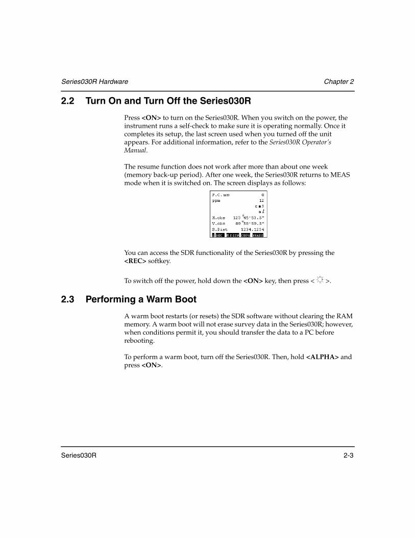
Press <ON> to turn on the Series030R. When you switch on the power, the instrument runs a self-check to make sure it is operating normally. Once it completes its setup, the last screen used when you turned off the unit appears. For additional information, refer to the Series030R Operator’s Manual.
The resume function does not work after more than about one week (memory back-up period). After one week, the Series030R returns to MEAS mode when it is switched on. The screen displays as follows:
You can access the SDR functionality of the Series030R by pressing the <REC> softkey.
To switch off the power, hold down the <ON> key, then press < >.
2.3 Performing a Warm Boot
A warm boot restarts (or resets) the SDR software without clearing the RAM memory. A warm boot will not erase survey data in the Series030R; however, when conditions permit it, you should transfer the data to a PC before rebooting.
To perform a warm boot, turn off the Series030R. Then, hold <ALPHA> and press <ON>.
Chapter 2 Series030R Hardware
2-4 Series030R
2.4 Performing a Cold Boot
A cold boot clears the RAM memory in the Series030R; in this case, you will lose all survey data. Only perform a cold boot when you cannot correct a fault in the system by performing a warm boot.
To perform a cold boot, hold the <F4>, <ALPHA>, <I> and <L> keys down, and press <ON>.
2.5 Accessing the Batteries
The Series030R uses a BDC35A battery (Ni-MH rechargeable, 6VDC) as its standard power source. Optionally, you can use the BDC12 (6VDC) as an external battery. In normal conditions at 25°C, the BDC35A battery can operate for approximately 5.5 hours.
The standard chargers for this instrument are the CDC39/40/48.
NOTE The BDC35A battery is not charged at the factory. You should fully charge the battery before you use it.
To care for the BDC35A battery, follow these general rules:
• Always switch the power off before removing the battery.• Store the battery in its case if when you are not using the instrument.
NOTE For more information about the BDC35A battery, refer to the Series030R Operator's Manual.
WARNING: Since all surveying data in the Series030R’s internal memory WILL BE LOST after a cold boot, remember to transfer your data to a personal computer before performing a cold boot.

Series030R Hardware Chapter 2
Series030R 2-5
Lithium battery
A lithium battery is used to power the Series030R memory. It ensures continuous memory so that all data is safe. The lithium battery contains enough power to back up the memory for approximately five years.
If the lithium battery becomes low, an error message — Backup lithium dead — will be displayed in REC mode.
If the lithium battery is completely discharged, all data will be cleared. Check periodically for this message.
WARNING! If you see this message, download the data to a personal computer or a memory card as soon as possible. If the lithium battery is completely discharged or removed, all data is cleared.
NOTE To replace the lithium battery, please contact your Sokkia distributor.
2.6 Accessing the Memory Card
The Series030R uses a CompactFlash (CF) memory card, which enables you to store data and transfer data between the instrument and a PC.
NOTE For details on how the Series030R communicates with memory cards, see Section 4.2.14, Card menu, Page 4-35.
2.6.1 Taking Precautions
Follow these precautions when you use memory cards so you do not lose the data stored on the card and instrument:
• Do not remove the CF card when the instrument is reading or writing data.
• Do not remove the battery or turn off the power when the instrument is reading or writing data.

Chapter 2 Series030R Hardware
2-6 Series030R
2.7 Inserting/removing the CompactFlash card
1. Slide in the button on the card cover and open the cover.
2. Insert the card until you hear a click.
3. Close the card cover. Press the card eject button to remove the card.
Series030R Hardware Chapter 2
Series030R 2-7
2.8 Storing the Series030R
If you plan to store the Series030R for an extended time, first transfer important data from the Series030R, then remove the battery pack and lithium cells.
NOTE Always switch the power off before removing the main battery.
When placing the Series030R in the carrying case, follow the layout plan. Make sure that the Series030R and protective lining of the carrying case are dry before closing the case. The case is hermetically sealed; if moisture is trapped inside, damage to the instrument could occur.
2.9 Servicing the Series030R
No servicing is required beyond battery service. If your Series030R develops a fault, transmit any data to your office computer and reset the Series030R with a cold boot as described in Section 2.4, Performing a Cold Boot, Page 2-4.
If you cannot transmit data, DO NOT perform a cold boot. Contact an authorized Sokkia distributor for advice.
2.10 Performing within Environment
The Series030R is designed to operate in temperatures in the range -4° F to +122° F (-20° C to +50° C). Humidity must be noncondensing.


Series030R 3-1
Chapter 3 Basic Operations
Familiarity with this chapter is essential to obtain high performance from your Series030R. This chapter introduces the basic keystrokes used with the Series 030R, the menu structure, and the format of data entry.
3.1 Understanding the Operating Modes
The Series030R operates in two modes, which you can quickly and easily transfer between as needed:
MEAS mode ................................. Accesses total station functionality. To switch to this mode, press <FNC> + <MEAS>. See Section 3.1.1, MEAS mode, Page 3-1.
REC mode ..................................... Accesses the SDR functionality. To switch to this mode, press the <REC> softkey. See Section 3.1.2, REC mode, Page 3-3.
3.1.1 MEAS mode
The MEAS mode give you access to the total station functions. That functionality is described in the Series030R Basic Operation Manual.
In this chapter
• Operating modes
• Keyboard layout and softkeys
• Data entry
• System messages and warnings
• Set password

Chapter 3 Basic Operations
3-2 Series030R
To access MEAS mode at any time, press <FNC> + <MEAS>. The following screen will display:
The following fields display in the MEAS mode:
P.C.mm........................Prism constant
ppm .............................Atmospheric correction
H.obs ...........................Horizontal angle right
HAL .............................Horizontal angle left
V.obs............................Zenith angle
VA ................................Vertical angle (horizontal = 0)
S.Dist ..........................Slope distance
H.Dist..........................Horizontal distance
V.Dist ..........................Height difference
N ..................................Numeral input
A...................................Alphabetical input
⊥+ .................................Tilt angle compensation on
..................................Remaining battery power (BDC35, temperature = 25°C, EDM on)
...............................Laser point is selected and ON
.................................Guidelight (optional function) is selected and ON
!.....................................Laser for measurement is emitted
3 90 to 100% 2 50 to 90%
1 10 to 50% 0 0 to 10%

Basic Operations Chapter 3
Series030R 3-3
.................................Prism
................................Reflective sheet
..................................Reflectorless
NOTE For more information, refer to the Series030R Operator's Manual.
3.1.1.1 MEAS mode and reading screens
If you press the MEAS softkey when you are in a Reading screen, you will see the message The observation must first be saved or discarded. Press any key. Press a key to return to the Reading screen without entering MEAS mode.
3.1.2 REC mode
This REC mode gives you access to the Series030R’s SDR functionality. Press the <REC> softkey to switch to REC mode. You will see this screen:

Chapter 3 Basic Operations
3-4 Series030R
3.2 Using the Keyboard
The Series030R has a 43-key keyboard (Figure 1).
Figure 1: Series030R keyboard layout
3.2.1 Power switch key
Use this key to turn on and turn off the Series030R.
Turn on ..........................................Press <ON> to turn on the power.
Turn off ..........................................Hold down the <ON> key and press
< >To turn off the power.
4 Softkeys 26 Alphanumeric keys
Backlight keyPower switch key
11 Operating keys
Basic Operations Chapter 3
Series030R 3-5
3.2.2 Backlight key
Use this key to control the following illumination:
Display/Reticle ............................Press < > to turn on and off the illumination for the display and reticle.
Laser Pointer/Guide Light .........You can press this key when you are in any SDR Reading or Take Reading screen to turn on and turn off the laser pointer or guide light.
NOTE To select between using the laser pointer or the guide light, you must be in MEAS mode (see Section 3.1.1, MEAS mode, Page 3-1).
3.2.3 Operating keys
The operating keys are as follows:
<ESC> .........................Exits mode (transfers to previous display); sets the data to 0; displays the instrument data in MEAS mode
<FNC> ........................Displays additional functions
<SFT> ..........................Changes letter from lower to uppercase
<BS> ............................Deletes a character
<SP> ............................Inputs a space
<↑> ...............................Moves to the top of the list, form or menu
<↓> ...............................Moves to the bottom of the list, form or menu
<↑> and <↓> ...............Move around and highlight the fields
<←> and <→> ...........Selects other options
< > ...................Generally accepts and stores data on the same line as the cursor, and then moves the cursor to the next line
<ALPHA>/<Num> ...Switches between alpha and numeric input
<Meas> .......................Transfers from REC mode to MEAS mode

Chapter 3 Basic Operations
3-6 Series030R
<View> .......................Displays data in the current job
<Note> ........................Enters a note
3.2.4 Softkeys
The bottom line of the Series030R screen presents available softkeys. A softkey is a software task that displays as a button on the bottom of the screen. Only the softkeys relevant to your current task appear.
You can press a softkey using the function keys <F1> through <F4> (located underneath the screen).
<F1>............................. Functions menu
<F2>............................. Survey menu
<F3>............................. Coordinate Geometry menu
<F4>............................. Road menu
In certain situations, more softkeys are available on additional pages. To access these pages, press <FNC>. A page indicator in the lower left corner of the display shows which page of the softkeys are being displayed. When no indicator displays, only one page of softkeys is available.
The <READ> softkey gives you a reading from the Series030R. It usually acts with the <F1> key.
Softkeys
Page indicator

Basic Operations Chapter 3
Series030R 3-7
3.2.4.1 Flashing indicators
At times, the softkeys will flash to indicate a mode or activity.
Guide light Active.......................When the guide light is active, the last position of the softkey row will flash between the alpha/numeric indicator and the guide light symbol.
Reading Laser...............................When the reading laser is active, the first position of the softkey row in the SDR Reading screen will continue to flash an exclamation point.
Laser Pointer.................................When the laser pointer is active, the last position of the softkey row will flash between the alpha/numeric indicator and the laser symbol.
3.3 Entering Data
This section describes how to enter values. All data entry is done using a screen “form.” A form is one or more data values (fields) that display on the screen together. For example, the Create job screen displays the following:
The screen shown in the above example constitutes a form. The fields are to the right and represent values for the job name, scale factor, point ID format, record elevation, curvature and refraction correction, and sea level correction.
Additional fields indicator

Chapter 3 Basic Operations
3-8 Series030R
If the number of fields in a form exceeds the space limitation on the first page, a second page is used to display the extra fields. The additional fields indicator (up or down arrow) in the right corner of the first and/or last fields signifies that more fields are accessible for that form. To view the additional pages, use the <↓> key on the last field or the <↑> key on the first field.
Steps to enter data
1. Use the <↑> and <↓> keys to move from field to field.
2. Enter data into the appropriate fields. The fields can be accessed in any order. For information on field types (numeric, alphanumeric, and option), see Section 3.3.1, Field types, Page 3-8.
3. Press <Enter> when all the fields contain acceptable values. The Series030R will continue processing. If you do not want to continue, press <ESC> twice.
NOTE The first time you press <ESC>, the field displays its original value. The second time you press <ESC>, the Series030R displays a message asking whether you want to discard all changes.
4. To edit data, highlight the field and press either <→> or <SP> to position the cursor on the first position in field or press either <←> or <BS> to position the cursor on the first position in field. Then make your editing changes or type a new value.
3.3.1 Field types
Three types of fields are available in screen forms:
• Numeric• Alphanumeric• Option

Basic Operations Chapter 3
Series030R 3-9
3.3.1.1 Numeric fields
Numeric fields include serial numbers and distance values. Numeric fields accept only the digits 0 through 9, decimal points, or a leading minus sign. When you enter in numeric fields, you will see a character indicator display an “N” on the bottom right of the display.
3.3.1.2 Alphanumeric fields
Alphanumeric fields include notes and observation codes. They can contain alphabetic (uppercase and lowercase), numeric characters and special characters such as +, -, and so on.
When you enter data in an alphanumeric field, you quickly can identify which character type will be entered by observing the character indicator in the bottom right corner of the screen.
The indicator displays as one of the following:
A...................................Upper-case alpha characters
a....................................Lower-case alpha characters
N ..................................Numbers and special characters
To toggle between upper- and lower-case alpha characters, press <SFT>. To toggle between alpha and numeric entries, press <ALPHA>.
Character indicator

Chapter 3 Basic Operations
3-10 Series030R
Special characters
The following characters can be used in alphanumeric fields. They are accessed as numeric entries (use <ALPHA> to toggle; an “N” should display in the bottom right-hand corner).
3.3.1.3 Option Fields
Option fields provide a list of possible selections, such as Yes/No options. The selections will toggle in the field when the <←> or <→> keys are pressed. The option that is displayed when you move to another field is the entry for that field. When you are in an option field, you cannot enter any alpha or numeric characters from the keypad. You must choose a selection from the choices provided.
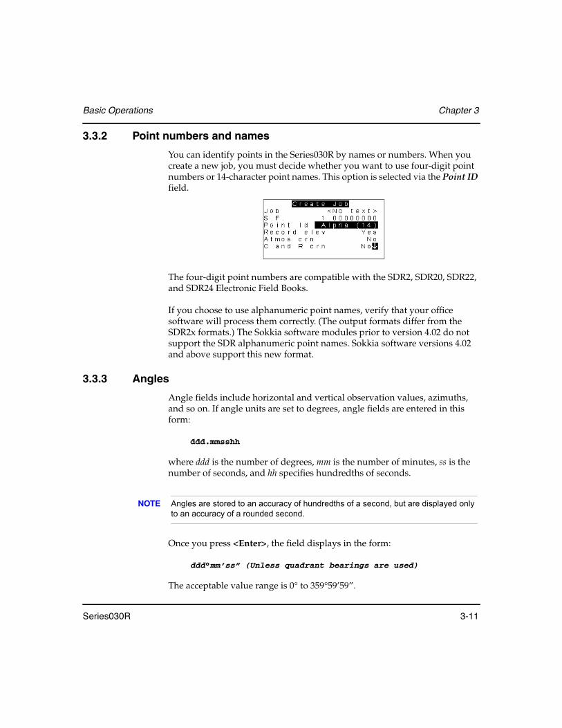
For example, the Point ID field can be changed from Alpha (14) to Numeric (4), by pressing <←> or <→>.
Numeric mode Numeric mode plus <SFT>
<A>.............................. :
<E> .............................. \
<I> ............................... >
<M>............................. <
<P> .............................. +
<R>.............................. (
<S> .............................. )
<T> .............................. -
<U>.............................. ?
<V>.............................. /
<W>............................. *
<A> ............................. @
<E> .............................. $
<M> ............................ #
<P> .............................. +
<Q> ............................. !
<R> ............................. [
<S> .............................. ]
<T>.............................. -
<U> ............................. ^
<V> ............................. %
<W> ............................ &
Basic Operations Chapter 3
Series030R 3-11
3.3.2 Point numbers and names
You can identify points in the Series030R by names or numbers. When you create a new job, you must decide whether you want to use four-digit point numbers or 14-character point names. This option is selected via the Point ID field.
The four-digit point numbers are compatible with the SDR2, SDR20, SDR22, and SDR24 Electronic Field Books.
If you choose to use alphanumeric point names, verify that your office software will process them correctly. (The output formats differ from the SDR2x formats.) The Sokkia software modules prior to version 4.02 do not support the SDR alphanumeric point names. Sokkia software versions 4.02 and above support this new format.
3.3.3 Angles
Angle fields include horizontal and vertical observation values, azimuths, and so on. If angle units are set to degrees, angle fields are entered in this form:
ddd.mmsshh
where ddd is the number of degrees, mm is the number of minutes, ss is the number of seconds, and hh specifies hundredths of seconds.
NOTE Angles are stored to an accuracy of hundredths of a second, but are displayed only to an accuracy of a rounded second.
Once you press <Enter>, the field displays in the form:
ddd°mm’ss” (Unless quadrant bearings are used)
The acceptable value range is 0° to 359°59’59”.

Chapter 3 Basic Operations
3-12 Series030R
If the angle units are set to gons (or mils), an angle field is entered and displayed as a decimal number of gons (or mils), for example 101.52.
3.3.4 Notes
Notes are used to enter additional information about an observation. A note can consist of three lines of 20 characters or a 60-character maximum. The note record is stored, printed, and transmitted as a continuous 60-character string, but is split on 20-character boundaries on the screen.
Notes can be entered into the database at any time by pressing <FNC> + <Note>. Notes also can be inserted into the database during database review (accessed by <FNC> + <View>). The note is inserted before the currently highlighted database record.
An example of a note in screen display is shown below:
The <TIME> softkey may be pressed to store the current time and date. The <FC ON>/<FC OFF> softkey is used to turn on or off feature codes.
Steps to enter a note
1. Enter descriptive notes into the database at any time by pressing <FNC> + <Note>. You will see this screen:
2. Enter the information.

Basic Operations Chapter 3
Series030R 3-13
3. To turn on or off the Feature Code Insert option, press the <FC ON> softkey or the <FC OFF> softkey. For more information, see Section 3.3.5, Feature codes within notes, Page 3-13, and Chapter 8, Feature Codes and Attributes.
You will not see the <FC ON> or <FC OFF> softkeys if the Code list active option is set to No on the Configure Reading screen.
NOTE When the <FC OFF> softkey is visible, the feature code insert option is On; pressing the <FC OFF> softkey turns this option Off. The same logic is true for the <FC ON> softkey. When this softkey is visible, the feature code insert option is Off.
4. Press <Enter> to store the note in the database, press <ESC> to discard it.
3.3.5 Feature codes within notes
Feature coding is the method of describing each point observed with an alphanumeric code. This feature is convenient if you are using lengthy, repetitive descriptions.
If you want to insert a feature code into a note, press the <FC ON> softkey. When you enter a note, the Series030R will open the feature code library (or stack) if it recognizes a word in the currently selected stack. If your word is in the feature code stack, select it by scrolling to it rather than manually entering it. For additional information on feature codes, see Chapter 8, Feature Codes and Attributes.
If you do not want a word from the feature code stack, press the <FC OFF> softkey. For example, if you want to enter the letters ST, and your list has an entry STCV, turn off the Feature code insert option and type in the letters.

Chapter 3 Basic Operations
3-14 Series030R
3.4 Understanding System Messages
Whenever the Series030R cannot continue its normal operation, it displays a warning message.
Two types of system messages exist. The first type displays a message on one line of the screen (just above the softkeys or on the top line), while the rest of the screen remains intact. The message remains until you press any key. For example:
The second type or error message clears the screen, displays the message, and instructs you to press any key to continue:
See Appendix A, System Messages, for a full list of system messages and explanations.

Series030R 4-1
Chapter 4 Understanding the Series030R Menu Structure
A menu provides a list of Series030R actions or selections. You access the menus with softkeys located at the bottom of the start-up screen or on the opening screen of any menu. Press <ESC> repeatedly to get to the start-up screen.
The Series030R has four main menus:
FUNC.......................... (Functions) Used to set up or start survey jobs; also controls all communications between the Series030R and any other devices like a PC (see Page 4-3).
SURV .......................... (Survey) Accesses programs frequently used in the field for data collection (see Page 4-43).
COGO ........................ (Coordinate Geometry) Performs coordinate geometry calculations and setting out field work (see Page 4-44).
ROAD......................... (Roading) Contains programs for road survey, definition, and set out (see Page 4-45).
In this chapter
• Menu structure and options
• Field details
• Options for the Functions and Configuration menus

Chapter 4 Understanding the Series030R Menu Structure
4-2 Series030R
Each menu lists several options that are organized according to specific tasks. The options available on a Series030R are shown in Figure 2.
Figure 2: Series030R SDR menu structure
4.1 Access a Menu Option
To perform a task with the Series030R, such as determining unit settings or setting out a line, you must access a menu option.
1. View the appropriate menu.
2. Highlight an option by moving the highlight bar with the <↑> and <↓> keys or by pressing the letter key that corresponds to the option’s first letter. If two or more options start with the same letter, press the letter key more than once.
3. Press <Enter> to select a highlighted option.
4. Press <ESC> to leave a menu without selecting any option.
Func Surv Cogo Road
JobInstrumentJob settingsConfigure readingTolerancesUnitsDate and timeJob deletionFeature code listHardwareCommunicationsDial-UpCard menuPasswordLanguage
TopographyTraverse adjustmentResectionSet collectionSet reviewBuilding face surveyCollimationTilt offsetRemote elevationKeyboard input
Set out coordsSet out lineSet out arcResectionInverseAreasIntersectionsPoint projectionTaping from baselineTransformationKeyboard input
Select roadSet out roadSet out road surfaceRoad topoCross-Section SurveyDefine roadReview roadDefine templateReview template
Understanding the Series030R Menu Structure Chapter 4
Series030R 4-3
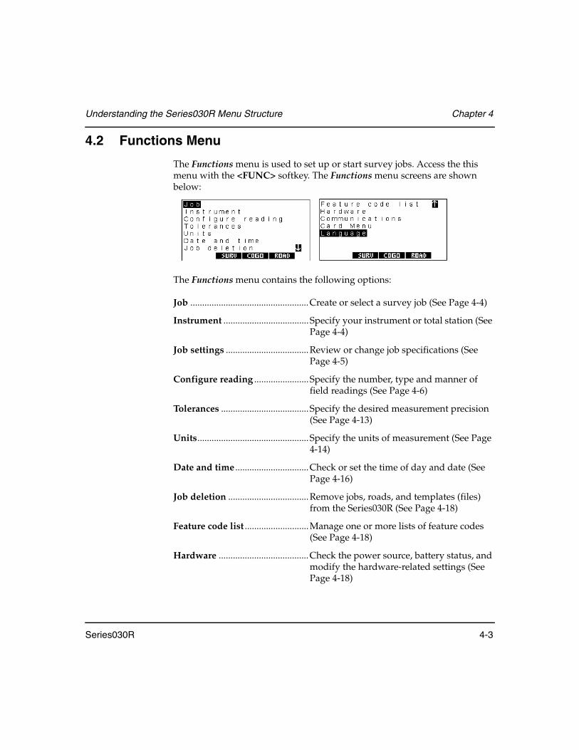
4.2 Functions Menu
The Functions menu is used to set up or start survey jobs. Access the this menu with the <FUNC> softkey. The Functions menu screens are shown below:
The Functions menu contains the following options:
Job ..................................................Create or select a survey job (See Page 4-4)
Instrument .................................... Specify your instrument or total station (See Page 4-4)
Job settings ...................................Review or change job specifications (See Page 4-5)
Configure reading ....................... Specify the number, type and manner of field readings (See Page 4-6)
Tolerances ..................................... Specify the desired measurement precision (See Page 4-13)
Units............................................... Specify the units of measurement (See Page 4-14)
Date and time ...............................Check or set the time of day and date (See Page 4-16)
Job deletion ..................................Remove jobs, roads, and templates (files) from the Series030R (See Page 4-18)
Feature code list ...........................Manage one or more lists of feature codes (See Page 4-18)
Hardware ......................................Check the power source, battery status, and modify the hardware-related settings (See Page 4-18)

Chapter 4 Understanding the Series030R Menu Structure
4-4 Series030R
Communications .........................Transfer data between the Series030R memory and a PC (See Page 4-21)
Dial-up ..........................................Transfer data to or from the instrument using a cellphone (See Page 4-21)
Card menu ....................................Transfer data to or from a memory card, format a card, and display and delete files from the card (See Page 4-35)
Password .......................................Enter or modify a password to protect settings (See Page 4-41)
Language .......................................Select the prompt language on the Series030R (See Page 4-42)
4.2.1 Job
The Job option is used to perform the following, which are further discussed in Chapter 5, Survey Jobs:
• Select an unfinished job from a list• Start a new job• Rename a job• Display the statistics of a job• Mark a job as a control job
4.2.2 Instrument
The instrument screen displays information about the instrument and give you access to various parameters.

Understanding the Series030R Menu Structure Chapter 4
Series030R 4-5
The Instrument Setup fields display the following information:
Instrument .................................... (information only) The type of instrument.
EDM desc ...................................... (information only) The type of EDM, which transmits in the instrument record.
EDM S/N ....................................... (information only) The six-digit numeric field for the EDM serial number, which transmits in the instrument record.
V.obs...............................................The vertical observation selector field displays if the instrument has more than one way of measuring its vertical angle. Zenith - angles are measured with the upward vertical representing 0°, and Horiz - angles are measure upwards from horizontal representing 0°.
Orient.............................................Controls the setting of the horizontal circle at the time of a backsight reading. Zero automatically sets the horizontal to zero; averaged F1/F2 values are not allowed, Azimuth automatically sets the computed azimuth; averaged F1/F2 values are not allowed, and None makes no change.
4.2.3 Job settings
The Job Setting option is discussed in Chapter 5, Survey Jobs.
Chapter 4 Understanding the Series030R Menu Structure
4-6 Series030R
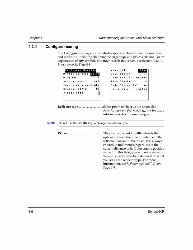
4.2.4 Configure reading
The Configure reading screen controls aspects of observation measurement and recording, including changing the target type and prism constant. For an explanation of any symbols you might see in this screen, see Section 4.2.4.1, Screen symbols, Page 4-9.
Reflector type ............................... Select prism or sheet as the target. See Reflector type and P.C. mm, Page 4-9 for more information about these changes.
NOTE Do not use the <Shift> key to change the reflector type.
P.C. mm..........................................The prism constant in millimetres is the optical distance from the plumb line to the reflective surface of the prism. It is always entered in millimetres, regardless of the current distance unit. If you enter a positive value into this field, you will see a warning. What displays in this field depends on what you set as the reflector type. For more information, see Reflector type and P.C. mm, Page 4-9.

Understanding the Series030R Menu Structure Chapter 4
Series030R 4-7
Auto pt num ................................. If you do not enter a point designator, this is the next designator that Series030R automatically suggests. Once a point designator has been suggested and accepted, the Series030R automatically adds an increment to determine the next value. For example, point 1000 is followed by 1001, and PIPE8 is followed by PIPE9 and then PIPF0. HELLO is followed by HELLP. The sequence continues until HELLZ, which is followed by HELMA.
Topo view stored .........................Stored observation records can be viewed in several forms. This field controls in which view observations are initially displayed using the topography program. Options are as follows:
NOTE Data is always stored internally in raw form. You can change the current view any time using the data view as described in Chapter 6, Viewing Survey Data. Topo view stored defines the initial view when the record is stored in the database. Also see Chapter 7, Coordinate Search Logic. For information on the options for outputting data, see Section 29.2, Specifying the output format of observations, Page 29-4.
Combine F1/F2 .............................When this field is set to Yes, the Topography program prompts you for two observations, one from each face of the instrument. The two readings are then combined to produce an averaged observation record.
Table 1: Observation Record Views
View Description
OBS Raw observation view
MC Measured and corrected view
RED Reduced view
POS Position view

Chapter 4 Understanding the Series030R Menu Structure
4-8 Series030R
# dis rdgs .......................................This field specifies the number of distance readings you will take for each point. Values from 1 to 9 are allowed. If 0 is used, an angles-only reading is taken.
Meas mode....................................This field controls the measurement mode between Fine, Rapid, and Track.
Meas mode repeat .......................When this field is set to Yes, the Series030R will measure the distance repeatedly. When set to No, a single measurement is taken. If you set Meas Mode to Rapid, this field is set to No and becomes non-editable. If you set Meas Mode to Track, this field is not available.
Code list active.............................When this field is set to Yes, any code field will use the feature code list for quick entry of codes as described in Chapter 8, Feature Codes and Attributes. When this field is set to No, use normal entry of alphanumeric data in the code field. See Code fields, Page 4-11 for variations.
Info blocks ....................................This field will split your note records into specific fields that contain different types of data. For more information, see Info blocks, Page 4-10.
Code fields....................................This field determines whether codes (on observations or point records) are split into sub-fields. For more information, see Code fields, Page 4-11.
Recip Calc .....................................This field specifies how the Series030R performs reciprocal vertical calculations. For more information, see Recip calc, Page 4-12.

Understanding the Series030R Menu Structure Chapter 4
Series030R 4-9
4.2.4.1 Screen symbols
The following symbols may appear on the Configure Reading screen.
4.2.4.2 Reflector type and P.C. mm
You can edit the Reflector or PC mm fields at any time except for two instances:
• The instrument is in the process of taking the reading.• The instrument has completed taking the reading but you have not yet
confirmed the reading.
The value that displays automatically in the PC mm field depends on what you set as the reflector type:
If you change the reflector type or the prism constant, and you previously saved an instrument record for this job, the Series030R will add an applicable note (reflector type or prism constant) to the job when you close this screen. Otherwise, the Series030R will add the note at the same time it writes the instrument record.
Table 2: Configure Reading Screen Symbols
Symbol Description Symbol Description
Battery Level Indicator Tilt On Indicator
Guide light Mark Series030R Prism Mark (reflector type = prism)
Laser Mark Series030R Sheet Mark (reflector type = sheet)
Reflectorless Mark (reflector type = none)
Reflector Set To Prism Displays Automatically
Prism The last prism constant used for prism
Sheet The last prism constant used for sheet
None 0

Chapter 4 Understanding the Series030R Menu Structure
4-10 Series030R
You can change the reflector type without having to set up a new instrument or new station. As well, changes you make to the reflector type only affect future observations and have no effect on observations you have already stored.
If you change the reflector type or prism constant while you are in MEAS mode (see Section 3.1.1, MEAS mode, Page 3-1), the Series030R will prompt you to decide if you want to discard the changes when you return to REC mode (see Section 3.1.2, REC mode, Page 3-3). If you answer Yes, the Series030R will restore the reflector type and the prism constant settings when you switch back to REC mode.
4.2.4.3 Info blocks
This feature provides compatibility with Wild’s Info Block style of data entry. It should not be confused with the Attribute definition capability of the Series030R’s feature code list, which is more powerful. Use this field to split your note records into specific fields that contain different types of data (information blocks).
Specify the number of extra fields that you want to fill in. If this number is zero, then a note is one continuous alphanumeric string up to 60 characters long. If the number of info blocks is more than zero, then entry of notes is done as a number of fields. The first field is called the codes, and subsequent fields are called “Info 1,” “Info 2” etc., up to the specified number of information blocks. The maximum number of blocks is five.
When you enter a non-zero number of information blocks, the following type of screen appears. Select whether the field should be numerical or alphanumeric by using the <←> or <→> key.
Press <Enter> when you have chosen Alpha or Numeric for each field.
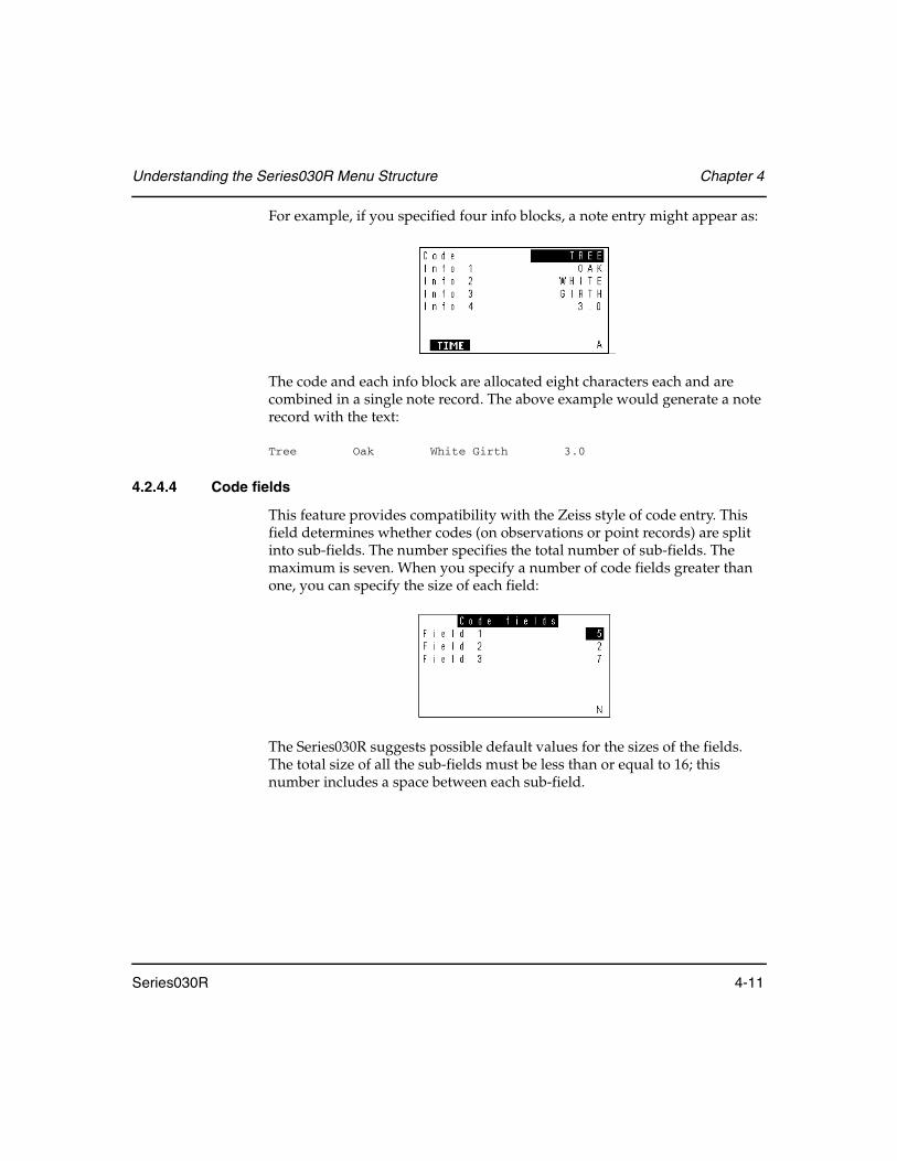
Understanding the Series030R Menu Structure Chapter 4
Series030R 4-11
For example, if you specified four info blocks, a note entry might appear as:
The code and each info block are allocated eight characters each and are combined in a single note record. The above example would generate a note record with the text:
Tree Oak White Girth 3.0
4.2.4.4 Code fields
This feature provides compatibility with the Zeiss style of code entry. This field determines whether codes (on observations or point records) are split into sub-fields. The number specifies the total number of sub-fields. The maximum is seven. When you specify a number of code fields greater than one, you can specify the size of each field:
The Series030R suggests possible default values for the sizes of the fields. The total size of all the sub-fields must be less than or equal to 16; this number includes a space between each sub-field.
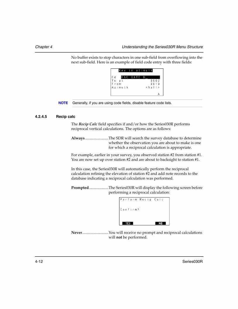
Chapter 4 Understanding the Series030R Menu Structure
4-12 Series030R
No buffer exists to stop characters in one sub-field from overflowing into the next sub-field. Here is an example of field code entry with three fields:
NOTE Generally, if you are using code fields, disable feature code lists.
4.2.4.5 Recip calc
The Recip Calc field specifies if and/or how the Series030R performs reciprocal vertical calculations. The options are as follows:
Always ........................The SDR will search the survey database to determine whether the observation you are about to make is one for which a reciprocal calculation is appropriate.
For example, earlier in your survey, you observed station #2 from station #1. You are now set up over station #2 and are about to backsight to station #1.
In this case, the Series030R will automatically perform the reciprocal calculation refining the elevation of station #2 and add note records to the database indicating a reciprocal calculation was performed.
Prompted....................The Series030R will display the following screen before performing a reciprocal calculation:
Never...........................You will receive no prompt and reciprocal calculations will not be performed.

Understanding the Series030R Menu Structure Chapter 4
Series030R 4-13
4.2.5 Tolerances
The Series030R checks observations for consistency within specified tolerances. These tolerances are used at several places in the software:
• When observations are made to a point using both faces of the instrument, the two readings are compared after the collimation correction is applied. This comparison happens in topography when the Combine F1/F2 configuration option is On. It also occurs during set collection if observations are being made on both faces. If the observations differ from the average by more than the specified tolerance, in the distances, vertical or horizontal angles, the Series030R will notify you.
• During set collection, each observation to a point is compared with the other observations to the same point. If the observation differs from the average by more than the specified tolerance, in distances or in vertical or horizontal angles, the Series030R will notify you.
• When reviewing sets of data, any observations that are out of tolerance will be marked with an asterisk.
• When you observe an existing point in topography, the Series030R will show you the difference between the expected observation and your actual observation. If this difference is out of tolerance, it will be indicated with an asterisk.
• When the Series030R performs a resection using a least squares adjust-ment, the weighting of the observations is derived from the tolerances. For this purpose, the tolerance is assumed to be the value of three stan-dard deviations (3σ).
4.2.5.1 Tolerance fields
The tolerance screens are used to specify the tolerances applied to observations. The tolerance screen is shown below.
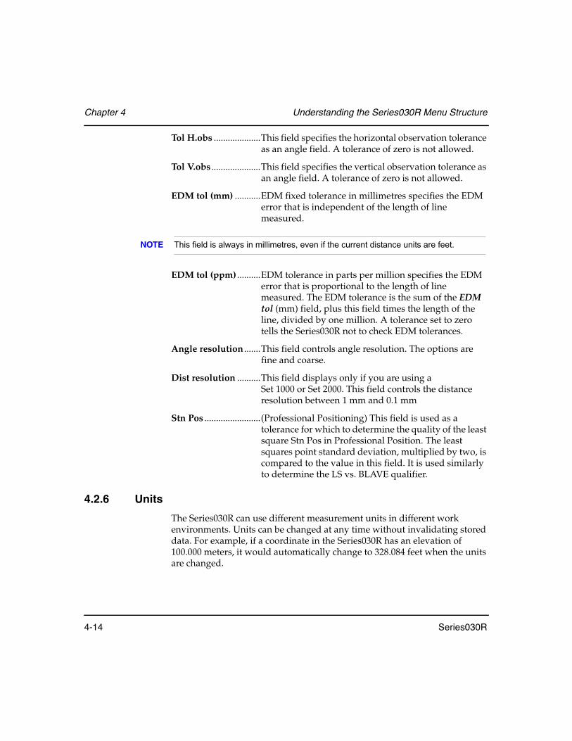
Chapter 4 Understanding the Series030R Menu Structure
4-14 Series030R
Tol H.obs ....................This field specifies the horizontal observation tolerance as an angle field. A tolerance of zero is not allowed.
Tol V.obs .....................This field specifies the vertical observation tolerance as an angle field. A tolerance of zero is not allowed.
EDM tol (mm) ...........EDM fixed tolerance in millimetres specifies the EDM error that is independent of the length of line measured.
NOTE This field is always in millimetres, even if the current distance units are feet.
EDM tol (ppm) ..........EDM tolerance in parts per million specifies the EDM error that is proportional to the length of line measured. The EDM tolerance is the sum of the EDM tol (mm) field, plus this field times the length of the line, divided by one million. A tolerance set to zero tells the Series030R not to check EDM tolerances.
Angle resolution .......This field controls angle resolution. The options are fine and coarse.
Dist resolution ..........This field displays only if you are using a Set 1000 or Set 2000. This field controls the distance resolution between 1 mm and 0.1 mm
Stn Pos ........................(Professional Positioning) This field is used as a tolerance for which to determine the quality of the least square Stn Pos in Professional Position. The least squares point standard deviation, multiplied by two, is compared to the value in this field. It is used similarly to determine the LS vs. BLAVE qualifier.
4.2.6 Units
The Series030R can use different measurement units in different work environments. Units can be changed at any time without invalidating stored data. For example, if a coordinate in the Series030R has an elevation of 100.000 meters, it would automatically change to 328.084 feet when the units are changed.

Understanding the Series030R Menu Structure Chapter 4
Series030R 4-15
After selecting Units from the Functions menu, the following settings are available:
Angle...........................Angle units apply to all horizontal and vertical angle measurements and azimuths. Units can be degrees, quadrant bearings, gons, or mils.
The Series030R assumes horizontal angles and azimuths are always measured turning to the right. Selecting quadrant bearing units only affects the display of bearings (30° displays as N30°E); the underlying units are still degrees.
The conversion factors are 90° = 100 gons and 90° = 1,600 mils.
Dist ..............................Distance units can be meters, International feet, or US feet. The unit chosen applies to all distances, lengths, and coordinates.
The conversion factor used is 1 International foot = 1.000002 US feet = 0.3048 meters.
For distances in land surveying, the difference between the International foot and the U.S. Survey foot is less significant than the error inherent in EDM instruments. However, this factor should be taken into account in certain situations, such as using state plane coordinate system values.
Pressure ......................Pressure units apply to the atmospheric pressure values. Units can be millimetres of mercury (mm Hg), inches of mercury (Inch Hg), or millibars (mbar). Conversion factors used are 1 Inch Hg = 25.4 mm Hg and 1,000 mbar = 750 mm Hg.
Temp ...........................Temperature units apply to the atmospheric temperature values. Units can be degrees Fahrenheit or degrees Celsius (Centigrade). The conversion formula used is °C = (°F - 32)/1.8.
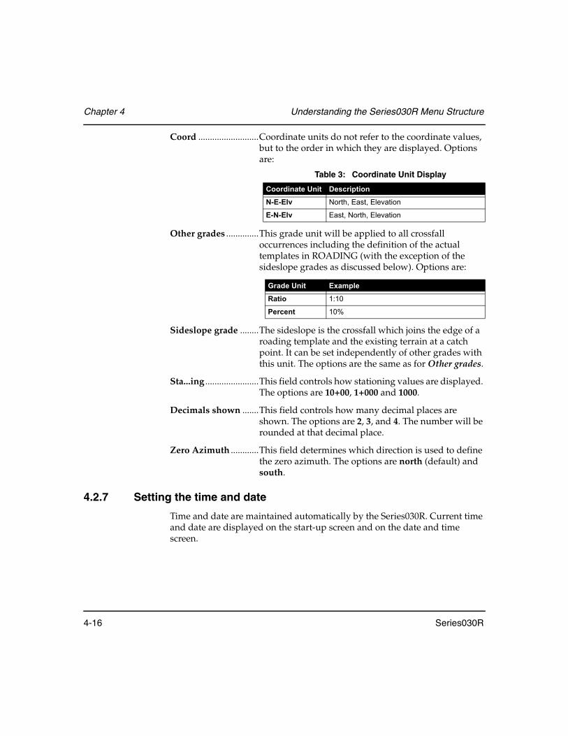
Chapter 4 Understanding the Series030R Menu Structure
4-16 Series030R
Coord ..........................Coordinate units do not refer to the coordinate values, but to the order in which they are displayed. Options are:
Other grades ..............This grade unit will be applied to all crossfall occurrences including the definition of the actual templates in ROADING (with the exception of the sideslope grades as discussed below). Options are:
Sideslope grade ........The sideslope is the crossfall which joins the edge of a roading template and the existing terrain at a catch point. It can be set independently of other grades with this unit. The options are the same as for Other grades.
Sta...ing .......................This field controls how stationing values are displayed. The options are 10+00, 1+000 and 1000.
Decimals shown .......This field controls how many decimal places are shown. The options are 2, 3, and 4. The number will be rounded at that decimal place.
Zero Azimuth ............This field determines which direction is used to define the zero azimuth. The options are north (default) and south.
4.2.7 Setting the time and date
Time and date are maintained automatically by the Series030R. Current time and date are displayed on the start-up screen and on the date and time screen.
Table 3: Coordinate Unit Display
Coordinate Unit Description
N-E-Elv North, East, Elevation
E-N-Elv East, North, Elevation
Grade Unit Example
Ratio 1:10
Percent 10%

Understanding the Series030R Menu Structure Chapter 4
Series030R 4-17
After selecting Date and time from the Functions menu, this screen appears:
Date format................This field controls date entry in the Date field. The options are DDMMYY and MMDDYY.
Date .............................The Date field shows the current date. Change it by entering a new date, in the form ddmmyy or mmddyy, depending on the Date format field setting.
Time ............................The Time field shows the current time. You can change it by entering a new time in the form hhmmss where hh is hours (in 24-hour form), mm is minutes, and ss is seconds. The Series030R generates automatic timestamp records as described below.
Time out .....................This field specifies the number of minutes that the Series030R will sit idle before it turns itself off.
For example, if this field is set to 5, and you do not touch the keyboard for 5 minutes, the Series030R will turn itself off. You cannot enter zero (0) as a setting. The minimum setting allowed is one minute.
Timestamp .................Timestamp is an automatic record of the time stored with data.
This field specifies the number of minutes between automatic timestamps. Whenever data is stored, the Series030R checks to see whether the specified length of time has elapsed since the last timestamp record. If it has, a new timestamp record is entered automatically.
If the timestamp interval is set to zero, the Series030R will not generate timestamps.
Timestamps can be inserted into the database using the <TIME> softkey when entering a note (see Section 3.3.5, Feature codes within notes, Page 3-13).

Chapter 4 Understanding the Series030R Menu Structure
4-18 Series030R
4.2.8 Job deletion
Use the Job deletion item to delete jobs, roads, templates, or all data from the Series030R. The following screen is displayed when Job deletion is selected.
For more information, see Section 5.7, Deleting a Job, Page 5-8.
4.2.9 Feature code list
See Chapter 8, Feature Codes and Attributes for details on the specification and use of feature codes and attributes.
4.2.10 Hardware
Hardware-related settings may be viewed and/or modified from this menu. You also can access system, set and SDR software information.
The main hardware screen displays hardware-related items.
Battery.........................Displays whether the main battery is producing sufficient voltage.
Backup ........................Displays whether the backup battery is producing sufficient voltage.
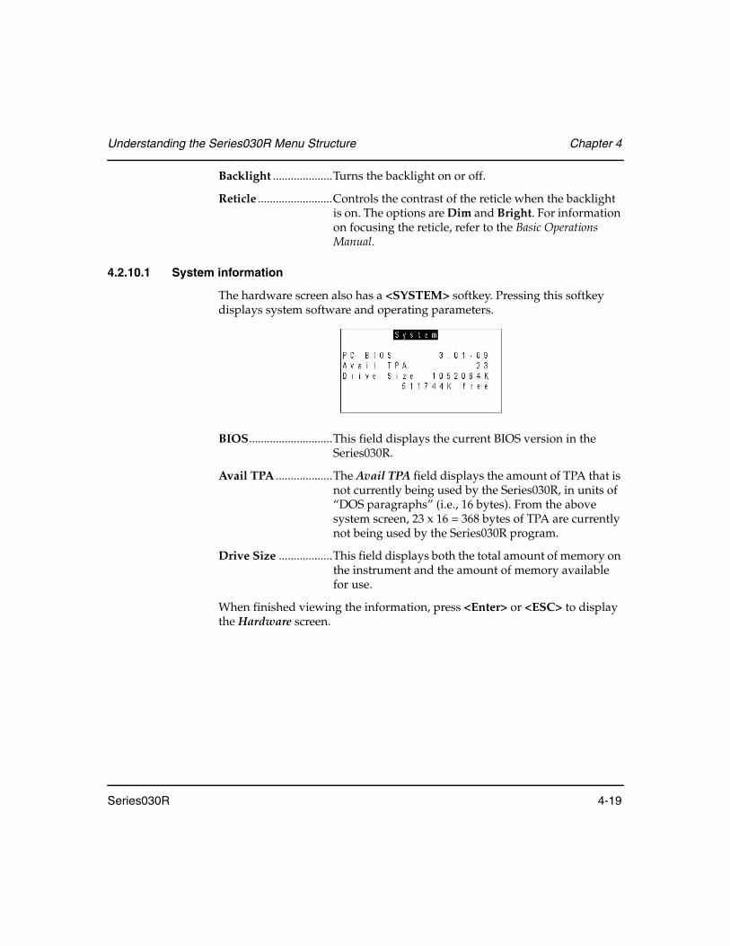
Understanding the Series030R Menu Structure Chapter 4
Series030R 4-19
Backlight ....................Turns the backlight on or off.
Reticle .........................Controls the contrast of the reticle when the backlight is on. The options are Dim and Bright. For information on focusing the reticle, refer to the Basic Operations Manual.
4.2.10.1 System information
The hardware screen also has a <SYSTEM> softkey. Pressing this softkey displays system software and operating parameters.
BIOS............................This field displays the current BIOS version in the Series030R.
Avail TPA ...................The Avail TPA field displays the amount of TPA that is not currently being used by the Series030R, in units of “DOS paragraphs” (i.e., 16 bytes). From the above system screen, 23 x 16 = 368 bytes of TPA are currently not being used by the Series030R program.
Drive Size ..................This field displays both the total amount of memory on the instrument and the amount of memory available for use.
When finished viewing the information, press <Enter> or <ESC> to display the Hardware screen.

Chapter 4 Understanding the Series030R Menu Structure
4-20 Series030R
4.2.10.2 SET information
The <SET> softkey displays information about your Series030R
EDM S/N ....................Serial number of your Series030R
SET ..............................Type of Series030R instrument
EDT BIOS ..................Current BIOS version of the EDT CPU.
When finished viewing the information, press <Enter> or <ESC> to display the Hardware screen.
4.2.10.3 SDR software information
The <VERSION> softkey displays information on the current version of SDR software running on your Series030R
When finished viewing the information, press <Enter> or <ESC> to display the Hardware screen.
4.2.11 Upgrade
Detailed instructions on how to upgrade are supplied with the upgrade software.
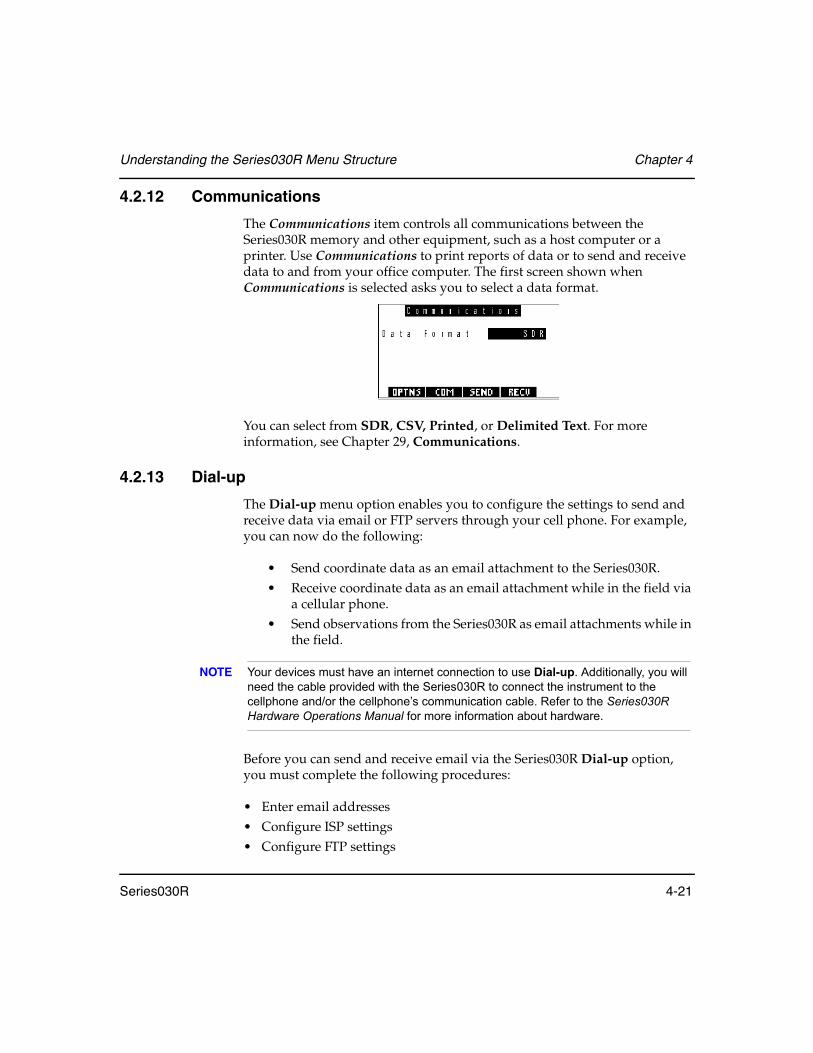
Understanding the Series030R Menu Structure Chapter 4
Series030R 4-21
4.2.12 Communications
The Communications item controls all communications between the Series030R memory and other equipment, such as a host computer or a printer. Use Communications to print reports of data or to send and receive data to and from your office computer. The first screen shown when Communications is selected asks you to select a data format.
You can select from SDR, CSV, Printed, or Delimited Text. For more information, see Chapter 29, Communications.
4.2.13 Dial-up
The Dial-up menu option enables you to configure the settings to send and receive data via email or FTP servers through your cell phone. For example, you can now do the following:
• Send coordinate data as an email attachment to the Series030R. • Receive coordinate data as an email attachment while in the field via
a cellular phone. • Send observations from the Series030R as email attachments while in
the field.
NOTE Your devices must have an internet connection to use Dial-up. Additionally, you will need the cable provided with the Series030R to connect the instrument to the cellphone and/or the cellphone’s communication cable. Refer to the Series030R Hardware Operations Manual for more information about hardware.
Before you can send and receive email via the Series030R Dial-up option, you must complete the following procedures:
• Enter email addresses• Configure ISP settings• Configure FTP settings
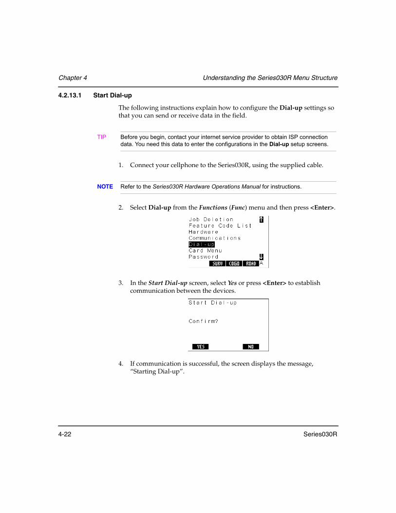
Chapter 4 Understanding the Series030R Menu Structure
4-22 Series030R
4.2.13.1 Start Dial-up
The following instructions explain how to configure the Dial-up settings so that you can send or receive data in the field.
TIP Before you begin, contact your internet service provider to obtain ISP connection data. You need this data to enter the configurations in the Dial-up setup screens.
1. Connect your cellphone to the Series030R, using the supplied cable.
NOTE Refer to the Series030R Hardware Operations Manual for instructions.
2. Select Dial-up from the Functions (Func) menu and then press <Enter>.
3. In the Start Dial-up screen, select Yes or press <Enter> to establish communication between the devices.
4. If communication is successful, the screen displays the message, “Starting Dial-up”.

Understanding the Series030R Menu Structure Chapter 4
Series030R 4-23
5. (optional) Enter your password and press <OK> or <Enter>.
NOTE If you forget your Dial-up password, you can reset it by cold booting the unit (see Section 2.4, Performing a Cold Boot, Page 2-4). However, cold booting will delete all job data as well as your Dial-up settings, so remember to first back up your data on the internal memory.
6. To continue without entering a password, press <Enter>. You see the Dial-up main menu screen.
7. Press <Exit> to return to the MEAS mode top screen.
4.2.13.2 Set up addresses
The following instructions explain how to enter the email addresses you need to send or receive emails.
1. Select <ADDR> in the Dial-up screen. The <Setup Mail Address> screen appears.
Dial-upPassword
NEW EXITAOK
Dial-upSend mailReceive mailFTP connect
FTP EXIT
Setup Mail [email protected]@[email protected]
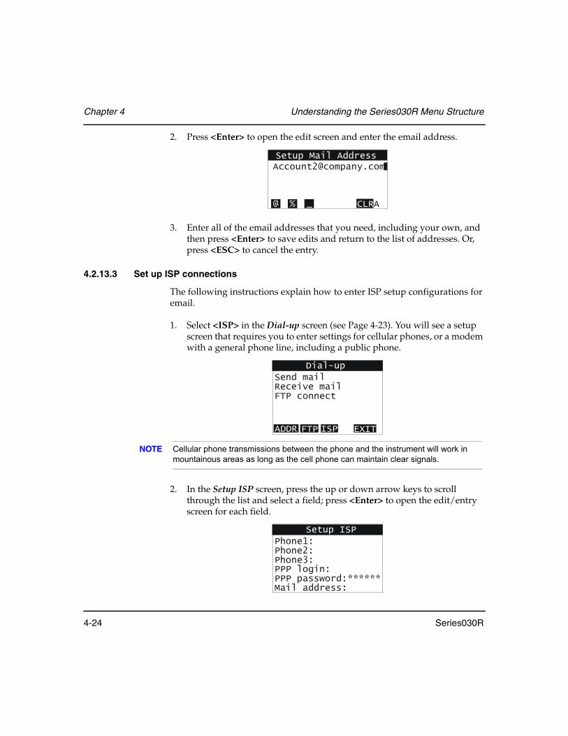
Chapter 4 Understanding the Series030R Menu Structure
4-24 Series030R
2. Press <Enter> to open the edit screen and enter the email address.
3. Enter all of the email addresses that you need, including your own, and then press <Enter> to save edits and return to the list of addresses. Or, press <ESC> to cancel the entry.
4.2.13.3 Set up ISP connections
The following instructions explain how to enter ISP setup configurations for email.
1. Select <ISP> in the Dial-up screen (see Page 4-23). You will see a setup screen that requires you to enter settings for cellular phones, or a modem with a general phone line, including a public phone.
NOTE Cellular phone transmissions between the phone and the instrument will work in mountainous areas as long as the cell phone can maintain clear signals.
2. In the Setup ISP screen, press the up or down arrow keys to scroll through the list and select a field; press <Enter> to open the edit/entry screen for each field.
Setup Mail [email protected]
A@ % _ CLR
Dial-upSend mailReceive mailFTP connect
FTP EXIT
Setup ISPPhone1:Phone2:Phone3:PPP login:PPP password:****** Mail address:

Understanding the Series030R Menu Structure Chapter 4
Series030R 4-25
NOTE Your internet service provider will give you the required settings for these fields. You will be able to edit them at any time.
3. When you complete the entry, press <Enter> to save the entry and continue to the next field.
4. To save the ISP setup configurations, press <ESC>. You return to the Dial-up screen.
4.2.13.4 Set up FTP connections
The following instructions explain how to configure the settings to connect to an ftp server via the internet.
NOTE Make sure you obtain the ftp settings from your ftp service provider before you continue.
1. Select <FTP> in the Dial-up screen (see Page 4-23). The Setup FTP Server screen appears.
Setup ISPTimeout (sec): 60
N CLR
Setup FTP ServerFtp.domain.comFtp.company.com

Chapter 4 Understanding the Series030R Menu Structure
4-26 Series030R
2. Use the up and down arrow keys to find the ftp server you want to set up and then press <Enter> to select the server and display its configuration screen.
3. Use the up and down arrow keys to scroll to and select a field for which you want to enter data, and then press <Enter> to open the field’s edit screen.
4. Enter the data, then press <Enter> to return to the Setup FTP Server Configuration screen.
5. Press <ESC> until you return to the main Dial-up menu screen.
If you have trouble receiving large files by ftp or email with your internet connection, try increasing the timeout (see Step 3., Section 4.2.13.3, Set up ISP connections, Page 4-24).
You can also try breaking the data into separate files; you can receive multiple files one at a time into the same job.
To break up an SDR job
• Open the file in a text editor and save the sections to additional files.
• Copy the 00NM header record from the top of the original file.
• Insert it as the first record in each additional file. The SDR software will merge the files back into one job as they are received.
Setup FTP ServerName:Phone:PPP login:PPP password:IP address: 0.0.0.0
Setup FTP ServerName:
@ % _ CLRA
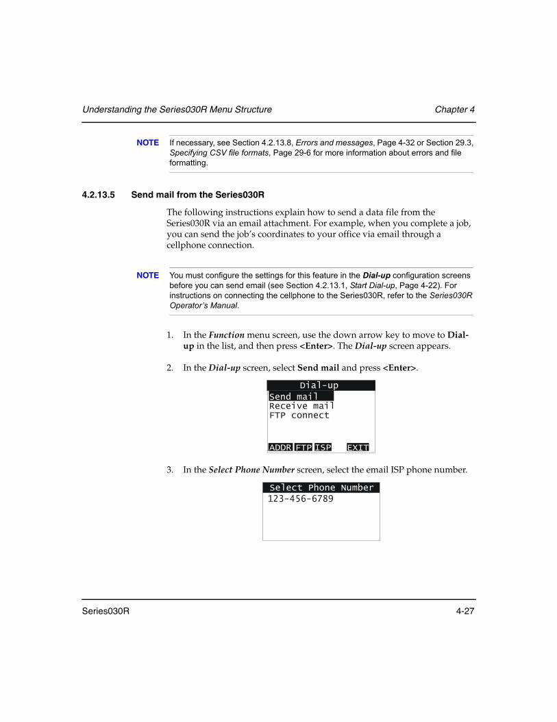
Understanding the Series030R Menu Structure Chapter 4
Series030R 4-27
NOTE If necessary, see Section 4.2.13.8, Errors and messages, Page 4-32 or Section 29.3, Specifying CSV file formats, Page 29-6 for more information about errors and file formatting.
4.2.13.5 Send mail from the Series030R
The following instructions explain how to send a data file from the Series030R via an email attachment. For example, when you complete a job, you can send the job’s coordinates to your office via email through a cellphone connection.
NOTE You must configure the settings for this feature in the Dial-up configuration screens before you can send email (see Section 4.2.13.1, Start Dial-up, Page 4-22). For instructions on connecting the cellphone to the Series030R, refer to the Series030R Operator’s Manual.
1. In the Function menu screen, use the down arrow key to move to Dial-up in the list, and then press <Enter>. The Dial-up screen appears.
2. In the Dial-up screen, select Send mail and press <Enter>.
3. In the Select Phone Number screen, select the email ISP phone number.
Dial-upSend mailReceive mailFTP connect
FTP EXIT
Select Phone Number123-456-6789
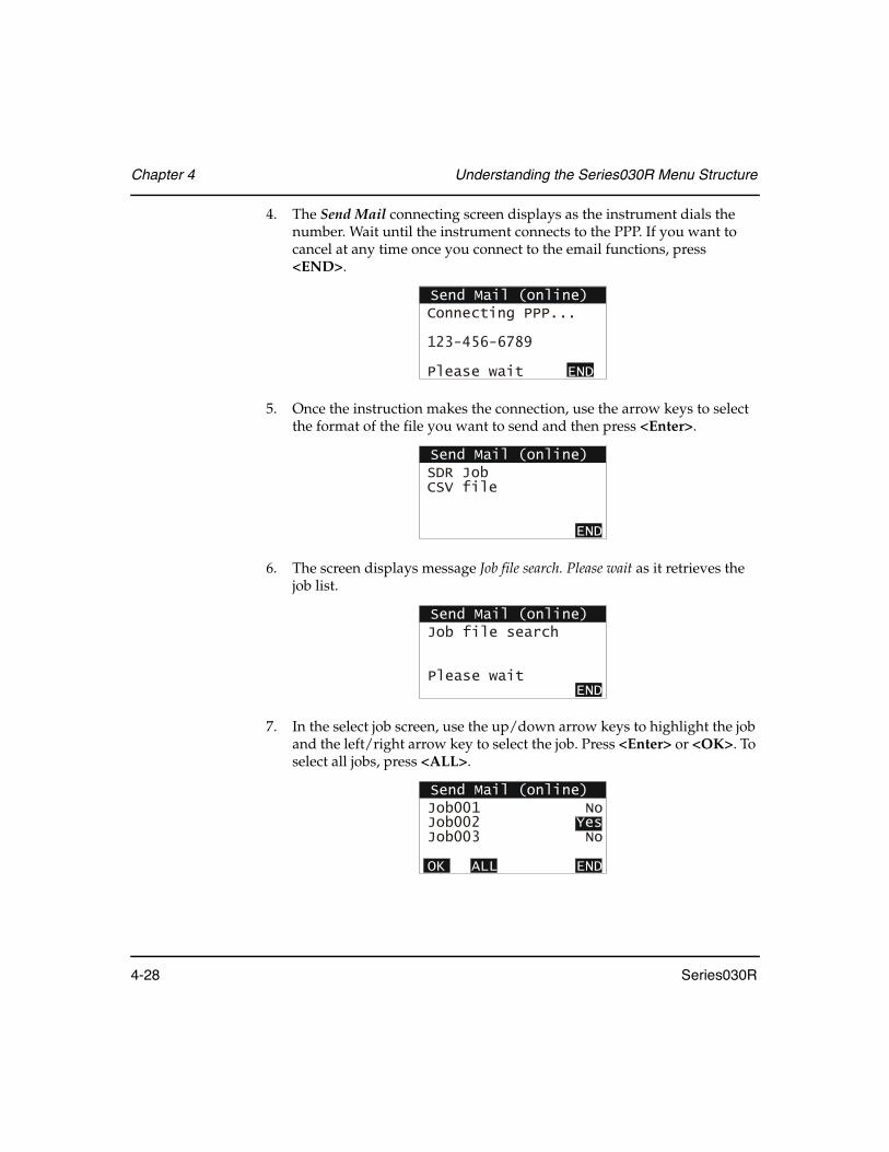
Chapter 4 Understanding the Series030R Menu Structure
4-28 Series030R
4. The Send Mail connecting screen displays as the instrument dials the number. Wait until the instrument connects to the PPP. If you want to cancel at any time once you connect to the email functions, press <END>.
5. Once the instruction makes the connection, use the arrow keys to select the format of the file you want to send and then press <Enter>.
6. The screen displays message Job file search. Please wait as it retrieves the job list.
7. In the select job screen, use the up/down arrow keys to highlight the job and the left/right arrow key to select the job. Press <Enter> or <OK>. To select all jobs, press <ALL>.
Send Mail (online)Connecting PPP...
123-456-6789
Please wait END
Send Mail (online)SDR JobCSV file
END
Send Mail (online)Job file search
Please wait END
Send Mail (online)Job001 NoJob002 Job003 No
Yes
OK ALL END
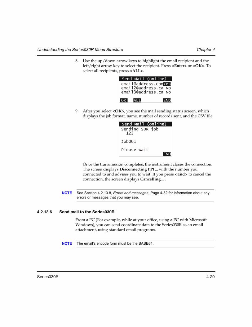
Understanding the Series030R Menu Structure Chapter 4
Series030R 4-29
8. Use the up/down arrow keys to highlight the email recipient and the left/right arrow key to select the recipient. Press <Enter> or <OK>. To select all recipients, press <ALL>.
9. After you select <OK>, you see the mail sending status screen, which displays the job format, name, number of records sent, and the CSV file.
Once the transmission completes, the instrument closes the connection. The screen displays Disconnecting PPP... with the number you connected to and advises you to wait. If you press <End> to cancel the connection, the screen displays Cancelling... .
NOTE See Section 4.2.13.8, Errors and messages, Page 4-32 for information about any errors or messages that you may see.
4.2.13.6 Send mail to the Series030R
From a PC (For example, while at your office, using a PC with Microsoft Windows), you can send coordinate data to the Series030R as an email attachment, using standard email programs.
NOTE The email’s encode form must be the BASE64.
Send Mail (online)[email protected]@address.ca No
No
Yes
OK ALL END
Send Mail (online)Send Mail (online)Sending SDR job 123
Job001
Please wait END

Chapter 4 Understanding the Series030R Menu Structure
4-30 Series030R
Send email
1. Start your email program and create a new email.
2. Enter the recipient’s address in the Address field.
3. In the Subject line, enter a file format tag followed by the job name, such as SDR> Job1. The file format tag must be SDR> for an SDR job file or CSV> for a delimited text file. When receiving email, the Series030R will only recognize emails with a valid file format tag and have an attachment. Subject prefixes such as RE: are ignored.
NOTE To avoid confusion about jobs from duplicated job names, it is recommended that you use different job file names when sending attachments to the Series030R.
4. Attach the data file. You can only attach one file per email; the Series030R will only read the attachment. You cannot carbon copy (cc:) these emails.
4.2.13.7 Receive mail
The following instructions explain how to receive email based on the configurations you set up in the Dial-up screens (see Section 4.2.13.1, Start Dial-up, Page 4-22; for example, you must configure dial-up settings before you can receive email).
1. In the Function menu screen, use the down arrow key to move to Dial-up in the list, and then press <Enter>. The Dial-up screen appears.
2. Select Receive mail.
Dial-upSend mail
FTP connectReceive mail
FTP EXIT
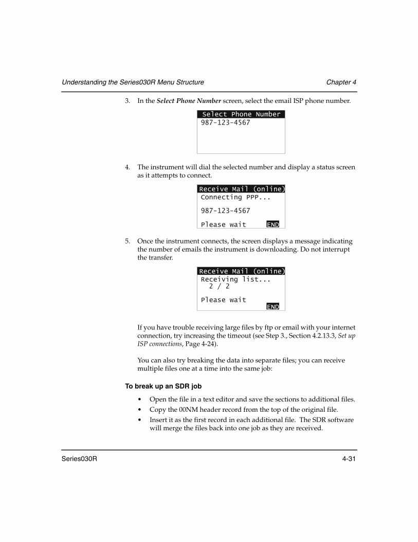
Understanding the Series030R Menu Structure Chapter 4
Series030R 4-31
3. In the Select Phone Number screen, select the email ISP phone number.
4. The instrument will dial the selected number and display a status screen as it attempts to connect.
5. Once the instrument connects, the screen displays a message indicating the number of emails the instrument is downloading. Do not interrupt the transfer.
If you have trouble receiving large files by ftp or email with your internet connection, try increasing the timeout (see Step 3., Section 4.2.13.3, Set up ISP connections, Page 4-24).
You can also try breaking the data into separate files; you can receive multiple files one at a time into the same job:
To break up an SDR job
• Open the file in a text editor and save the sections to additional files. • Copy the 00NM header record from the top of the original file.• Insert it as the first record in each additional file. The SDR software
will merge the files back into one job as they are received.
Select Phone Number987-123-4567
Receive Mail (online)Connecting PPP...
Please wait
987-123-4567
END
Receive Mail (online)Receiving list... 2 / 2
Please wait END

Chapter 4 Understanding the Series030R Menu Structure
4-32 Series030R
NOTE If necessary, see Section 4.2.13.8, Errors and messages, Page 4-32 or Section 29.3, Specifying CSV file formats, Page 29-6 for more information about errors and file formatting.
6. Once the instrument completes the download, the screen displays a list of emails prefaced by the file format tag. Use the up/down arrow keys to highlight the file you want to open. Press <RECV> to select the file.
7. Once you select the email, you will see a message indicating the number of records per file being downloaded. Do not interrupt the transfer.
NOTE If the instrument rejects points in a CSV file because they already exist in the current SDR job, the screen will display the number of records successfully imported, followed by a slash and the total number of records downloaded. See Section 4.2.13.8, Errors and messages, Page 4-32 for more information about errors.
The Dial-up feature will automatically disconnect once the file is downloaded. You will see Disconnecting POP... pop.server.com Please wait, followed by Disconnecting PPP... and the phone number as the instrument closes the connections.
4.2.13.8 Errors and messages
Remember to check your settings, connections, and entries, as well as to make sure your files are valid before you transfer data. Refer to the following table for information about errors or messages that you may see while sending or receiving files.
Receive Mail (online)SDR>Job001CSV>Stakeout
RECV END
Receive Mail (online)Receiving CSV file 123 / 134CSV>StakeOutPlease wait
RECV END
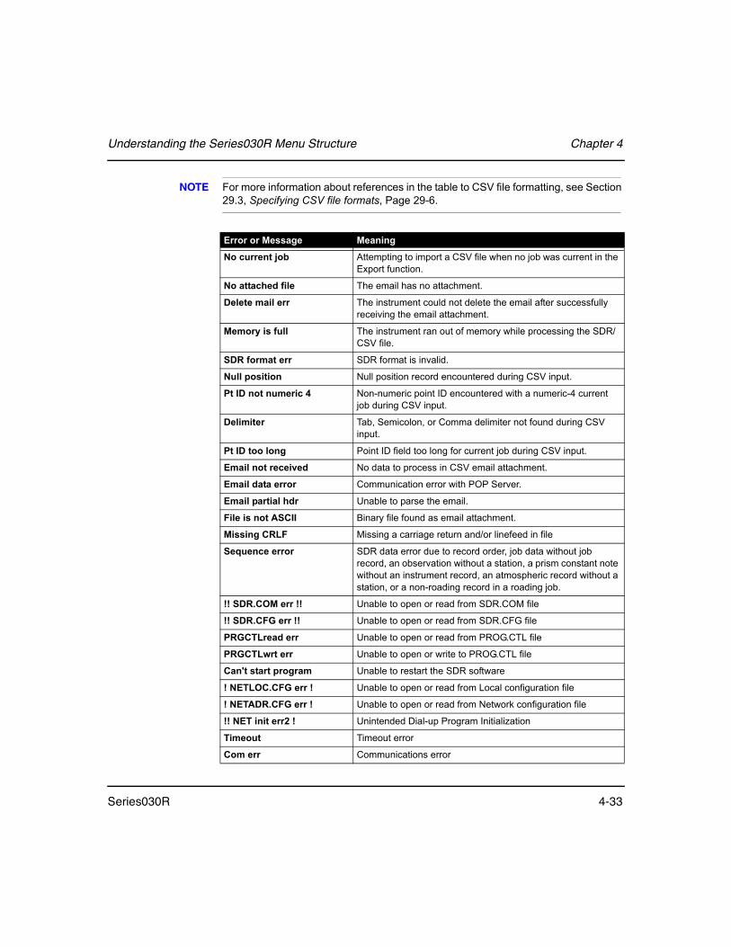
Understanding the Series030R Menu Structure Chapter 4
Series030R 4-33
NOTE For more information about references in the table to CSV file formatting, see Section 29.3, Specifying CSV file formats, Page 29-6.
Error or Message Meaning
No current job Attempting to import a CSV file when no job was current in the Export function.
No attached file The email has no attachment.
Delete mail err The instrument could not delete the email after successfully receiving the email attachment.
Memory is full The instrument ran out of memory while processing the SDR/CSV file.
SDR format err SDR format is invalid.
Null position Null position record encountered during CSV input.
Pt ID not numeric 4 Non-numeric point ID encountered with a numeric-4 current job during CSV input.
Delimiter Tab, Semicolon, or Comma delimiter not found during CSV input.
Pt ID too long Point ID field too long for current job during CSV input.
Email not received No data to process in CSV email attachment.
Email data error Communication error with POP Server.
Email partial hdr Unable to parse the email.
File is not ASCII Binary file found as email attachment.
Missing CRLF Missing a carriage return and/or linefeed in file
Sequence error SDR data error due to record order, job data without job record, an observation without a station, a prism constant note without an instrument record, an atmospheric record without a station, or a non-roading record in a roading job.
!! SDR.COM err !! Unable to open or read from SDR.COM file
!! SDR.CFG err !! Unable to open or read from SDR.CFG file
PRGCTLread err Unable to open or read from PROG.CTL file
PRGCTLwrt err Unable to open or write to PROG.CTL file
Can't start program Unable to restart the SDR software
! NETLOC.CFG err ! Unable to open or read from Local configuration file
! NETADR.CFG err ! Unable to open or read from Network configuration file
!! NET init err2 ! Unintended Dial-up Program Initialization
Timeout Timeout error
Com err Communications error
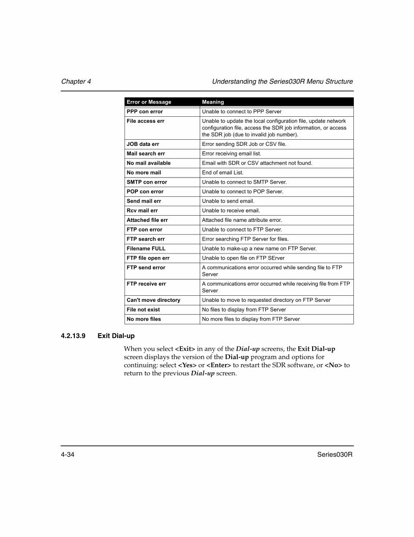
Chapter 4 Understanding the Series030R Menu Structure
4-34 Series030R
4.2.13.9 Exit Dial-up
When you select <Exit> in any of the Dial-up screens, the Exit Dial-up screen displays the version of the Dial-up program and options for continuing: select <Yes> or <Enter> to restart the SDR software, or <No> to return to the previous Dial-up screen.
PPP con error Unable to connect to PPP Server
File access err Unable to update the local configuration file, update network configuration file, access the SDR job information, or access the SDR job (due to invalid job number).
JOB data err Error sending SDR Job or CSV file.
Mail search err Error receiving email list.
No mail available Email with SDR or CSV attachment not found.
No more mail End of email List.
SMTP con error Unable to connect to SMTP Server.
POP con error Unable to connect to POP Server.
Send mail err Unable to send email.
Rcv mail err Unable to receive email.
Attached file err Attached file name attribute error.
FTP con error Unable to connect to FTP Server.
FTP search err Error searching FTP Server for files.
Filename FULL Unable to make-up a new name on FTP Server.
FTP file open err Unable to open file on FTP SErver
FTP send error A communications error occurred while sending file to FTP Server
FTP receive err A communications error occurred while receiving file from FTP Server
Can't move directory Unable to move to requested directory on FTP Server
File not exist No files to display from FTP Server
No more files No more files to display from FTP Server
Error or Message Meaning

Understanding the Series030R Menu Structure Chapter 4
Series030R 4-35
4.2.14 Card menu
The Series030R can perform the following card management functions:
4.2.14.1 Formatting a memory card
The Flash card must be formatted to work properly with the Series 030R.
1. Select Card menu from the Functions menu.
2. Select the Format card option to format the card.
3. Follow the remaining instructions on the screen to complete formatting the card.
Warning: Formatting the memory card deletes all previously stored data on the card.
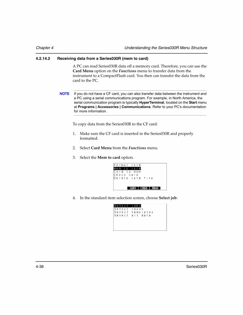
Chapter 4 Understanding the Series030R Menu Structure
4-36 Series030R
4.2.14.2 Receiving data from a Series030R (mem to card)
A PC can read Series030R data off a memory card. Therefore, you can use the Card Menu option on the Functions menu to transfer data from the instrument to a CompactFlash card. You then can transfer the data from the card to the PC.
NOTE If you do not have a CF card, you can also transfer data between the instrument and a PC using a serial communications program. For example, in North America, the serial communication program is typically HyperTerminal, located on the Start menu at Programs | Accessories | Communications. Refer to your PC’s documentation for more information.
To copy data from the Series030R to the CF card:
1. Make sure the CF card is inserted in the Series030R and properly formatted.
2. Select Card Menu from the Functions menu.
3. Select the Mem to card option.
4. In the standard item selection screen, choose Select job:

Understanding the Series030R Menu Structure Chapter 4
Series030R 4-37
5. When you see a list of available jobs, use the <↑> and <↓> keys to highlight the name of the job you want to copy to the card.
NOTE If no jobs are available, a warning message displays.
6. Press <Enter>. You see the following screen:
7. Enter the file name for copying and press <Enter>, or use the softkeys to perform the following actions:
<OPTIONS> ..............Specifies the view to be copied. The details on this option are described in Section 29.2, Specifying the output format of observations, Page 29-4.
<LISTS> .....................Displays a list of the files in the card.
The Series030R will copy the selected jobs to individual files on the memory card. If a job file with the same name already exists, you will be asked to confirm whether or not to overwrite the file.
8. Remove the CF card from the Series030R and insert it in the PC’s memory card drive.
9. Use the PC’s copy files function to copy files from the card to the PC. For more information, refer to your PC's system documentation.
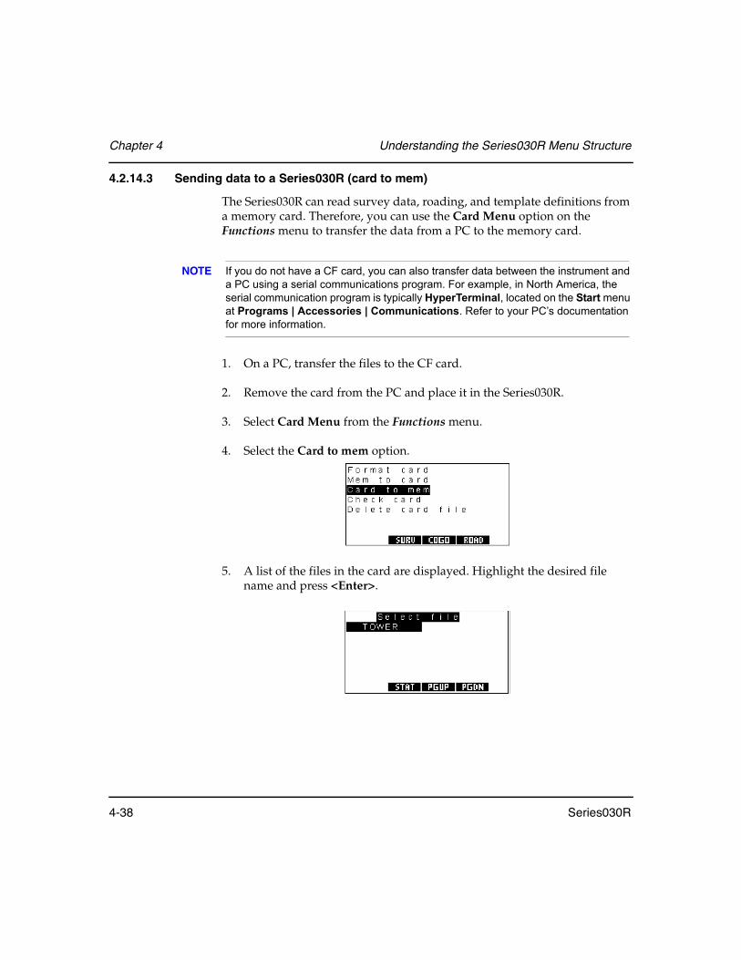
Chapter 4 Understanding the Series030R Menu Structure
4-38 Series030R
4.2.14.3 Sending data to a Series030R (card to mem)
The Series030R can read survey data, roading, and template definitions from a memory card. Therefore, you can use the Card Menu option on the Functions menu to transfer the data from a PC to the memory card.
NOTE If you do not have a CF card, you can also transfer data between the instrument and a PC using a serial communications program. For example, in North America, the serial communication program is typically HyperTerminal, located on the Start menu at Programs | Accessories | Communications. Refer to your PC’s documentation for more information.
1. On a PC, transfer the files to the CF card.
2. Remove the card from the PC and place it in the Series030R.
3. Select Card Menu from the Functions menu.
4. Select the Card to mem option.
5. A list of the files in the card are displayed. Highlight the desired file name and press <Enter>.

Understanding the Series030R Menu Structure Chapter 4
Series030R 4-39
6. The Series030R reads the selected files from the memory card. A screen displays to show the transfer status. When the transfer is complete, press any key to continue.
4.2.14.4 Checking the memory card statistics
1. Select Card menu from the Functions menu.
2. Select the Check card option to check the status of the card.
3. The following screen displays the card information.
Data ................................................ (information only) Displays the type of card - Data or Program - currently retained in the Series030R
Size ................................................. (information only) Displays the card’s total capacity
Format............................................ (information only) Displays the card’s format type

Chapter 4 Understanding the Series030R Menu Structure
4-40 Series030R
Battery............................................ (information only) Displays the card’s battery condition
Free memory................................. (information only) Displays the remaining card capacity
Write protect ................................Determines the write protect status of the card
4. Press <Enter> to accept changes or <ESC> to return to the Card menu.
4.2.14.5 Deleting memory card files
1. Select Card menu from the Functions menu.
2. Select the Delete card file option:
3. The list of files on the card will be displayed:
4. Set the value of each file you want to delete to Yes and press the <Enter>. To delete all files in the memory card, press the <ALL> softkey.
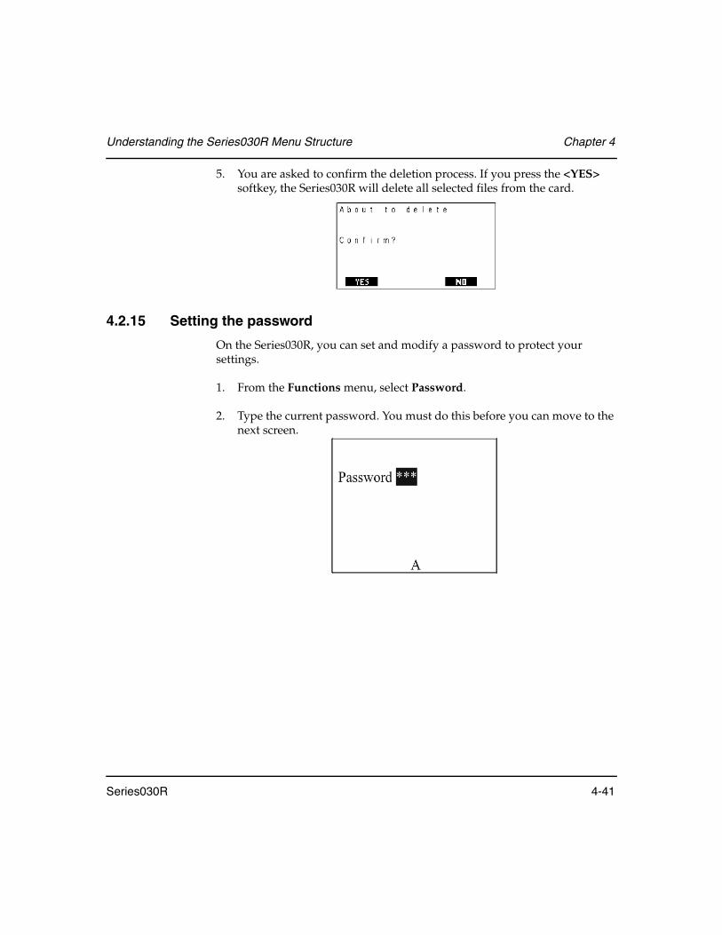
Understanding the Series030R Menu Structure Chapter 4
Series030R 4-41
5. You are asked to confirm the deletion process. If you press the <YES> softkey, the Series030R will delete all selected files from the card.
4.2.15 Setting the password
On the Series030R, you can set and modify a password to protect your settings.
1. From the Functions menu, select Password.
2. Type the current password. You must do this before you can move to the next screen.
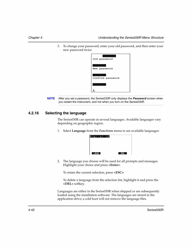
Chapter 4 Understanding the Series030R Menu Structure
4-42 Series030R
3. To change your password, enter your old password, and then enter your new password twice.
NOTE After you set a password, the Series030R only displays the Password screen when you restart the instrument, and not when you turn on the Series030R.
4.2.16 Selecting the language
The Series030R can operate in several languages. Available languages vary depending on geographic region.
1. Select Language from the Functions menu to see available languages:
2. The language you choose will be used for all prompts and messages. Highlight your choice and press <Enter>.
To retain the current selection, press <ESC>.
To delete a language from the selection list, highlight it and press the <DEL> softkey.
Languages are either in the Series030R when shipped or are subsequently loaded using the installation software. The languages are stored in the application drive; a cold boot will not remove the language files.
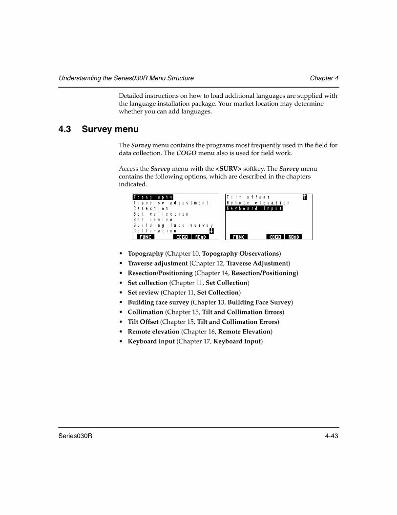
Understanding the Series030R Menu Structure Chapter 4
Series030R 4-43
Detailed instructions on how to load additional languages are supplied with the language installation package. Your market location may determine whether you can add languages.
4.3 Survey menu
The Survey menu contains the programs most frequently used in the field for data collection. The COGO menu also is used for field work.
Access the Survey menu with the <SURV> softkey. The Survey menu contains the following options, which are described in the chapters indicated.
• Topography (Chapter 10, Topography Observations)• Traverse adjustment (Chapter 12, Traverse Adjustment)• Resection/Positioning (Chapter 14, Resection/Positioning)• Set collection (Chapter 11, Set Collection)• Set review (Chapter 11, Set Collection)• Building face survey (Chapter 13, Building Face Survey)• Collimation (Chapter 15, Tilt and Collimation Errors)• Tilt Offset (Chapter 15, Tilt and Collimation Errors)• Remote elevation (Chapter 16, Remote Elevation)• Keyboard input (Chapter 17, Keyboard Input)

Chapter 4 Understanding the Series030R Menu Structure
4-44 Series030R
4.4 COGO menu
The COGO menu contains programs used frequently in the field for coordinate geometry calculations and setting out field work. The Survey menu can also be used for field work.
Access the COGO menu with the <COGO> softkey. It contains the following options, which are described in the chapters indicated.
• Set out coordinates (Chapter 18, Set Out Design Coordinates)• Set out line (Chapter 19, Set Out Line)• Set out arc (Chapter 20, Set Out Arc)• Resection/Positioning (Chapter 14, Resection/Positioning)• Inverse (Chapter 21, Inverse)• Areas (Chapter 22, Area Calculation and Subdivision)• Intersections (Chapter 23, Intersections)• Point projection (Chapter 25, Point Projections)• Taping from the Baseline (Chapter 24, Taping from Baseline)• Transformations (Chapter 26, Transformations)• Keyboard input (Chapter 17, Keyboard Input)
Resection and Keyboard input are in this menu, as well as in the Survey menu, since these options are useful in both.
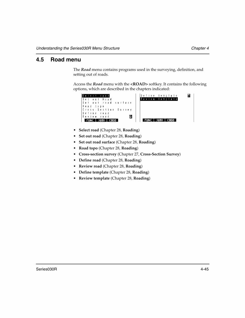
Understanding the Series030R Menu Structure Chapter 4
Series030R 4-45
4.5 Road menu
The Road menu contains programs used in the surveying, definition, and setting out of roads.
Access the Road menu with the <ROAD> softkey. It contains the following options, which are described in the chapters indicated:
• Select road (Chapter 28, Roading)• Set out road (Chapter 28, Roading)• Set out road surface (Chapter 28, Roading)• Road topo (Chapter 28, Roading)• Cross-section survey (Chapter 27, Cross-Section Survey)• Define road (Chapter 28, Roading)• Review road (Chapter 28, Roading)• Define template (Chapter 28, Roading)• Review template (Chapter 28, Roading)

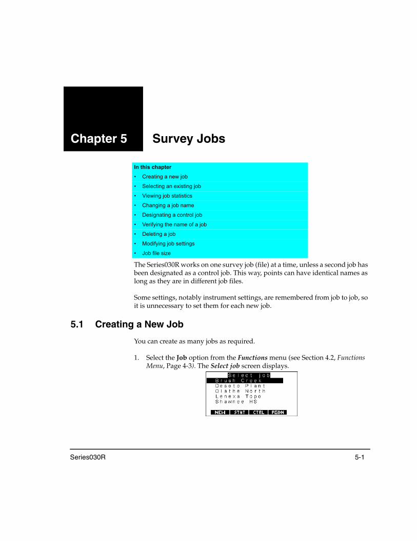
Series030R 5-1
Chapter 5 Survey Jobs
The Series030R works on one survey job (file) at a time, unless a second job has been designated as a control job. This way, points can have identical names as long as they are in different job files.
Some settings, notably instrument settings, are remembered from job to job, so it is unnecessary to set them for each new job.
5.1 Creating a New Job
You can create as many jobs as required.
1. Select the Job option from the Functions menu (see Section 4.2, Functions Menu, Page 4-3). The Select job screen displays.
In this chapter
• Creating a new job
• Selecting an existing job
• Viewing job statistics
• Changing a job name
• Designating a control job
• Verifying the name of a job
• Deleting a job
• Modifying job settings
• Job file size

Chapter 5 Survey Jobs
5-2 Series030R
NOTE If no jobs are available in the Series030R, the Create Job screen appears when you select Job from the Functions menu.
2. Press the <NEW> softkey to display the Create Job screen.
3. Enter information in the following fields
NOTE Most values may be changed with Job settings on the Functions menu. For more information, see Section 4.7, Job settings.
Job ...............................This field holds the name of a new job. Enter a name with any combination of letters and numbers, up to 16 characters long. Do not use a period (.) within a job name.
S.F. ...............................(Cannot be changed later) This field holds the Scale Factor of the job. This is a plane scale factor, so if your job is using a transverse mercator projection you will need to calculate a suitable scale factor for your work area.
The scale factor is applied whenever observations are reduced to generate coordinates. It is also applied in reverse to generate set out measurements.
Point ID ......................(Cannot be changed later) This field specifies the length and type of point names in the job. The two options are as follows:
Table 4: Point ID Field Length
Field Length Description
Numeric 4 Point names contain four digits; compatible with the SDR20 series of data collectors.
Alpha 14 Point names may contain 14 characters, both letters and digits.

Survey Jobs Chapter 5
Series030R 5-3
NOTE If you choose to use alphanumeric point names, verify that your office software will process them correctly. (The output formats differ from the SDR2x formats.) The Sokkia software modules prior to version 4.02 do not support the alphanumeric point names. Sokkia software versions 4.02 and above support this new format.
Record elev ................(Cannot be changed later) The Series030R generally expects that points are in three-dimensional space. However, if you want to assume that all or some points lie in a plane, set the Record elev to No. Points will be assigned the same (indeterminate) elevation.
NOTE When Record elev is set to No, corrected records are given a vertical angle of 90°. This forces all subsequent calculations to take place in two-dimensional (horizontal) space.
Atmos crn ...................If atmospheric correction is set to Yes, the Series030R applies an atmospheric correction to observations based on the current temperature, pressure and humidity values. Calculation details are given in Section 31.2.2, Pressure and temperature correction, Page 31-4.
ppm setup ..................(Available only when Atmos crn is set to Yes) PPM setup allows you to determine which atmospheric values to use in determining the atmospheric correction. The options are Press/Temp, Press/Temp/Humid and ppm input. The first two settings ask for appropriate data upon station setup. Ppm input uses the value directly input in MEAS mode ppm input.
C and R crn ................If curvature and refraction correction are set to Yes, the Series030R applies a correction to allow for the curvature of the earth and refraction of the EDM beam through the atmosphere. Calculation details are given in Section 31.3.1, Curvature and refraction correction, Page 31-8.

Chapter 5 Survey Jobs
5-4 Series030R
Refract const ..............(Available only when C and R crn is set to Yes) The refraction constant is the coefficient of refraction used in the calculation of curvature and refraction correction. It is a selector field with the options 0.14 and 0.20.
Sea level crn...............If sea level correction is set to Yes, the Series030R reduces a horizontal distance at the elevation of the instrument station to the corresponding (shorter) sea level chord when generating coordinates. Calculation details are given in Section 31.3.2, Sea level correction, Page 31-8.
4. Once you have set these job parameters, press <Enter>.
5. The Note screen displays. You can then enter an unlimited number of job notes. Press <Enter> when finish entering notes.
5.2 Opening an Existing Job
You can access an existing survey job with the following steps.
1. Select Job from the Functions menu. The Select job screen displays.
2. Use <↑> and <↓> to highlight the name of the job you want.

Survey Jobs Chapter 5
Series030R 5-5
3. When a job name is highlighted, press <View> to review the data in the job and verify that this is the job you want.
4. Press <ESC> or <Enter> to return to job selection.
5. Press <Enter>. The selected job will become the current job.
5.3 Accessing Job Statistics
The <STAT> softkey displays the job statistics for the job selected on the Select job screen. A typical statistics screen is shown below:
ID.................................Displays and allows modification of the job name
Job size (k) .................Displays the size of the job, in kilobytes, that the job currently occupies in memory.
Recs used....................Displays the approximate number of records (point positions, observations, notes, etc.) currently stored in the job.
Date and Time ...........Displays the date and time that the job was last accessed. The date and time will not necessarily relate to the last time data was saved in the job. For example, selecting a job as the current job accesses the job files and updates the date and time.
Point count.................Displays the number of points currently stored. A new job will have a point count of 0.
Press <Enter> or <ESC> to return the Select job screen.

Chapter 5 Survey Jobs
5-6 Series030R
5.4 Renaming a Job
You can change the name of an existing job with the following steps.
1. Highlight the name of the job on the Select job screen and press the <STAT> softkey. This will present you with a screen similar to the following.
2. The ID field displays the current name for the job. You can edit this field to enter the new name for the job.
3. Press <Enter> to complete the entry and change the job name. You will then be returned to the Select job screen with the new job name displayed.
5.5 Specifying a Control Job
Often, when you are working within a job, you want to use points that already are present in another job. The <CTRL> softkey allows you to “tag” a job to act as the “control” job. Once you have done this, if you specify a point name that does not exist in the job you are currently working on, the Series030R also will search through the control job to see if a point with the specified name exists within it. If the point exists in the control job, the point details will automatically be copied into the current job ready for use within the job. If the specified point does not exist in either the current or control job, the standard Search failed message will be displayed, and you will be given the opportunity to enter the point details.
Only one job can be tagged as a control job at any one time.
Control jobs will usually work even if the current job and control job have different point ID types. The Series030R searches for the best point name match. For example, “12” in an alphanumeric point job matches “0012” in a numeric point job and vice versa.
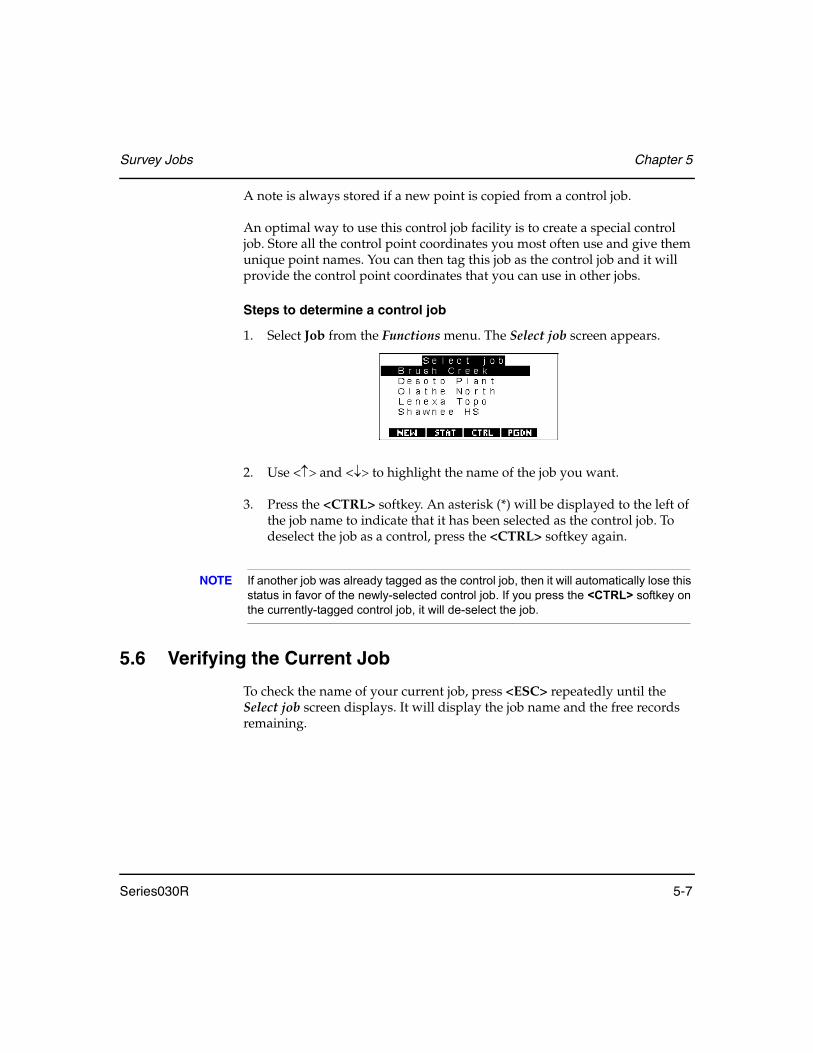
Survey Jobs Chapter 5
Series030R 5-7
A note is always stored if a new point is copied from a control job.
An optimal way to use this control job facility is to create a special control job. Store all the control point coordinates you most often use and give them unique point names. You can then tag this job as the control job and it will provide the control point coordinates that you can use in other jobs.
Steps to determine a control job
1. Select Job from the Functions menu. The Select job screen appears.
2. Use <↑> and <↓> to highlight the name of the job you want.
3. Press the <CTRL> softkey. An asterisk (*) will be displayed to the left of the job name to indicate that it has been selected as the control job. To deselect the job as a control, press the <CTRL> softkey again.
NOTE If another job was already tagged as the control job, then it will automatically lose this status in favor of the newly-selected control job. If you press the <CTRL> softkey on the currently-tagged control job, it will de-select the job.
5.6 Verifying the Current Job
To check the name of your current job, press <ESC> repeatedly until the Select job screen displays. It will display the job name and the free records remaining.
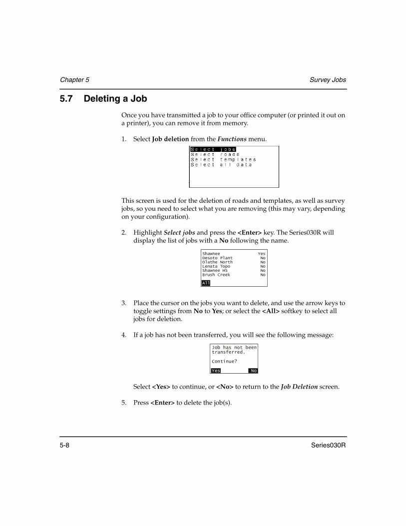
Chapter 5 Survey Jobs
5-8 Series030R
5.7 Deleting a Job
Once you have transmitted a job to your office computer (or printed it out on a printer), you can remove it from memory.
1. Select Job deletion from the Functions menu.
This screen is used for the deletion of roads and templates, as well as survey jobs, so you need to select what you are removing (this may vary, depending on your configuration).
2. Highlight Select jobs and press the <Enter> key. The Series030R will display the list of jobs with a No following the name.
3. Place the cursor on the jobs you want to delete, and use the arrow keys to toggle settings from No to Yes; or select the <All> softkey to select all jobs for deletion.
4. If a job has not been transferred, you will see the following message:
Select <Yes> to continue, or <No> to return to the Job Deletion screen.
5. Press <Enter> to delete the job(s).
Shawnee YesDesoto Plant NoOlathe North NoLenata Topo NoShawnee HS NoBrush Creek No
All
Job has not beentransferred.
Continue?
Yes No

Survey Jobs Chapter 5
Series030R 5-9
5.8 Modifying Job Settings
You can review the choices you made when you created a job. Select Job setting from the Functions menu to display the Job settings screen:
The Job settings screen lets you change some of the options on the Create job screen. You cannot change the point ID type, scale factor or records elevation choices that you selected at creation time. Changes made on the Job settings screen do not affect data that has already been collected. These changes affect only subsequent data points.
If anything on this screen is changed, a NOTE JS will be saved on the database. This note contains a four-digit sequence.
This note record is primarily used by a software package (For example, Sokkia software). It will not indicate to you anything other than when job settings were changed.
Table 5: NOTE JS Sequence
Digit in Sequence Represents Entry options
First Atmospheric Corrections 0 = Off1 = On
Second Curvature and Refraction Correction
0 = Off1 = On
Third Refraction Constant 0 = 0.14 refraction constant1 = 0.20 refraction constant
Fourth Sea Level Corrections 0 = Off0 = On

Chapter 5 Survey Jobs
5-10 Series030R
5.9 Determining Job Sizes
The job size in the Series030R is limited only by the available memory. However, for practical reasons, you should split your work into smaller blocks. Using the control job helps makes this easier because you can easily access control coordinates, even from a new job.
The Series030R will indicate when the memory is becoming full and when it is completely full. Once full, transfer one or more jobs to a PC or CF card, and then delete them.
The memory capacity of the Series030R is 1 MB. You can also use CompactFlash cards, which are available in a range of sizes, from 32 MB to 128 MB. It is recommended that you use a CF card with large storage capacity.

Series030R 6-1
Chapter 6 Viewing Survey Data
View stored Series030R data at any time by pressing <VIEW>. You see the following screen:
Each line corresponds to one record in the Series030R SDR database. New records are added to the end of the database so record order is chronological. The only exception is NOTE records, which can be added anywhere in the database when viewing recorded data. The note is entered immediately before the record currently highlighted (see Section 3.3.4, Notes, Page 3-12).
Information displayed for each record includes record type, the derivation code (indicates which part of the program generated the record), and the first data field of the record.
In this chapter
• Viewing stored data
• Searching for data
• Editing notes and codes
• Observation views

Chapter 6 Viewing Survey Data
6-2 Series030R
6.1 Reviewing the Database
From the initial database review screen, you can view a list of the records corresponding to the current job.
When this screen is first accessed, the highlight bar is on the last record. The <↑> and <↓> move the highlight bar forward or backward one record at a time. Several softkeys also are available to help you navigate in review mode:
<SRCH> .....................Allows you to search backward or forward for a particular point name or code.
<SHFT> ......................Toggles the last two softkeys from <PREV> and <NEXT> to <PGUP> and <PGDN>
<PREV> ......................Moves you to the previous occurrence of the record type you have currently highlighted. For example, if a station (STN) record is highlighted, pressing <PREV> moves the highlight bar to the next station in the database.
<NEXT>......................Moves you to the previous (or next) occurrence of the record type you have currently highlighted.
<PGUP> .....................Move up a full screen
<PGDN> ....................Move down a full screen
To exit from the database, press <ESC>. The last screen accessed before entering the database will display.
<SHFT>

Viewing Survey Data Chapter 6
Series030R 6-3
6.2 Performing a Survey Data Search
You can search the database for records containing a particular point or code or both. Press the <SRCH> softkey and this screen displays:
Enter the point name in the Pt field and/or the code in the Code field. Press <Enter> or the <PREV> softkey to search backward or the <NEXT> softkey to search forward. The first matching record is highlighted. You now can open that record or repeat the steps to continue your search.
If both a point name and a code are entered, Series030R first looks for point names matches. If none are found, then it searches for code matches.
If no matches are found, the following message displays:
Searching for coordinates
If you want to find out what coordinates the Series030R will use for a particular point name, specify the point name for a new station setup. You can do this by entering the Topography program, (see Chapter 10, Topography Observations for more information).
Enter the point name in the Stn field. The Series030R then displays the point coordinates if it knows them or can calculate them.

Chapter 6 Viewing Survey Data
6-4 Series030R
6.3 Opening a Record for Viewing
You can open any record displayed in the database list.
1. Select the record whose fields you want to view.
2. Press <→> to open it.
3. If more fields are available for this record, a double arrow will display in the last field. To view these fields, press <→>.
4. Use the <EDIT> softkey to edit notes and codes.
5. The <↑> and <↓> keys open the next adjacent record in the indicated direction.
6. To return to the database list, press <ESC>, <Enter> or <←>. Exit out of review mode by pressing <ESC> or <Enter> from the database list.
6.4 Editing Notes and Codes
Most of the information stored in the database records cannot be edited. However, you can modify codes or notes, with the exception of program-generated notes, such as Traverse closure information.
Steps for editing records
1. Open the record to be edited.

Viewing Survey Data Chapter 6
Series030R 6-5
2. If the <EDIT> softkey is not initially displayed in the record screen, press <FNC> to view a second page of softkeys.
3. Press the <EDIT> softkey.
4. Make your modifications to the code or note.
5. Press <Enter> when you are finished or <ESC> to exit edit mode. Press <Enter>, <ESC> or <←> to return to the database list.
6.5 Reviewing Observation Records
When you open an observation record (OBS), this screen displays:
The data shown in an OBS screen has the prism constant and atmospheric corrections applied (if applicable). No other corrections, such as instrument/target height, curvature and refraction are applied.
The three softkeys at the bottom of the screen, refer to different views you can see of this observation. The initial view measurement is the view specified in the Topo view stored field in the Configure reading option under the Functions menu. So when you take an observation and then review it, you will not necessarily see the raw data.
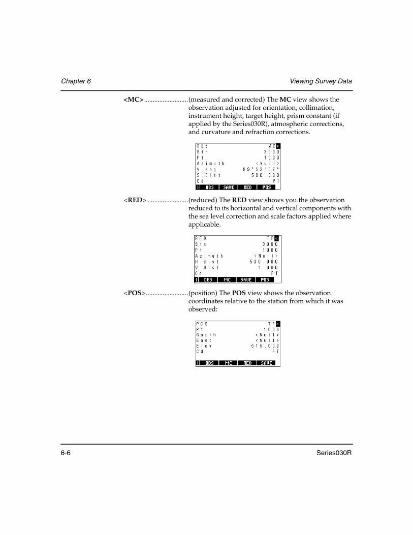
Chapter 6 Viewing Survey Data
6-6 Series030R
<MC> ..........................(measured and corrected) The MC view shows the observation adjusted for orientation, collimation, instrument height, target height, prism constant (if applied by the Series030R), atmospheric corrections, and curvature and refraction corrections.
<RED> ........................(reduced) The RED view shows you the observation reduced to its horizontal and vertical components with the sea level correction and scale factors applied where applicable.
<POS>.........................(position) The POS view shows the observation coordinates relative to the station from which it was observed:
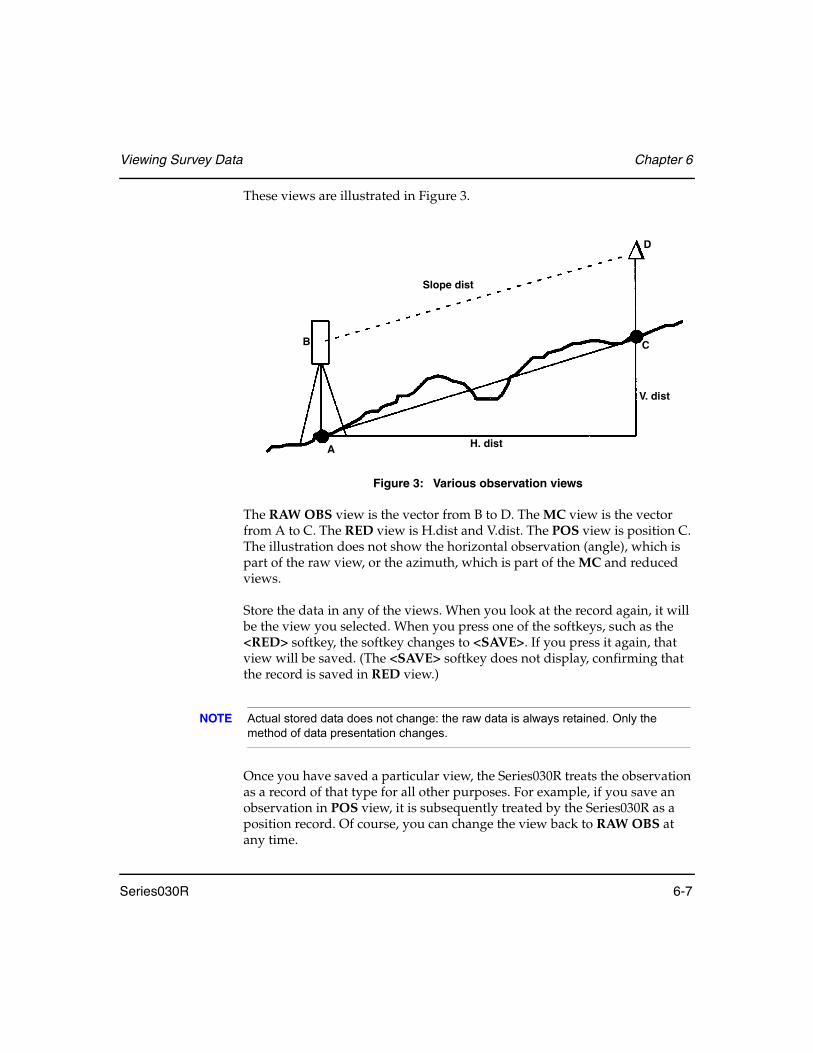
Viewing Survey Data Chapter 6
Series030R 6-7
These views are illustrated in Figure 3.
Figure 3: Various observation views
The RAW OBS view is the vector from B to D. The MC view is the vector from A to C. The RED view is H.dist and V.dist. The POS view is position C. The illustration does not show the horizontal observation (angle), which is part of the raw view, or the azimuth, which is part of the MC and reduced views.
Store the data in any of the views. When you look at the record again, it will be the view you selected. When you press one of the softkeys, such as the <RED> softkey, the softkey changes to <SAVE>. If you press it again, that view will be saved. (The <SAVE> softkey does not display, confirming that the record is saved in RED view.)
NOTE Actual stored data does not change: the raw data is always retained. Only the method of data presentation changes.
Once you have saved a particular view, the Series030R treats the observation as a record of that type for all other purposes. For example, if you save an observation in POS view, it is subsequently treated by the Series030R as a position record. Of course, you can change the view back to RAW OBS at any time.
A
B C
D
Slope dist
V. dist
H. dist

Chapter 6 Viewing Survey Data
6-8 Series030R
NOTE The Series030R does not permit you to view a backsight observation as anything other than an OBS. This avoids problems caused by recoordinating a backsight point.
When you transfer job data, you can transfer observation records in more than one view. The default action is to transmit in the current view. Use the <OPTNS> softkey on the Data Format screen to select views before transmission. The Data Format screen is displayed by selecting Communications in the Functions menu.
For example, you can choose to output your observations in both RAW OBS and POS view. Your printout or transmission contains two lines for each record, one showing the raw data and one showing the coordinated data. Because this calculation is done at transmission time, it requires no memory for storage. For more information, see Chapter 29, Communications.
NOTE The ability to store observations in RAW OBS view or POS view has useful implications when combined with the Series030R's search rules for calculating coordinates. For example, you can store your observation to override or ignore particular observations after they have been sorted (see Chapter 7, Coordinate Search Logic, for details). If you feel an observation is especially accurate, store it in POS view. The Series030R uses this observation view to calculate coordinates.

Series030R 7-1
Chapter 7 Coordinate Search Logic
A POS view record is, most typically, an observation (OBS) in position (POS) view. However, MC and RED records can also be stored in POS view. These three types of POS view records (OBS in POS view, MC in POS view, and RED in POS view) are equal in precedence to true POS (or STN) records in the coordinate search rules.
When the Series030R program searches for the coordinates of a point, it always uses the latest information, except that POS and POS view records are used before more recent OBS records.
The Series030R searches for the latest coordinates of the station point to calculate the target's coordinates from the observation.
Coordinates are one of the following:
• Station record (STN)• Position record (POS)
Coordinates can be calculated from one of the following:
• An observation record (OBS) stored in POS view• An observation record stored in raw or reduced view• A reduced record (RED)
See Chapter 30, SDR Database, for information on the records stored in the Series030R SDR database.
In this chapter
• Coordinate search rules for total station instruments
• Application of total station coordinate search rules

Chapter 7 Coordinate Search Logic
7-2 Series030R
7.1 Understanding the Search Rules
When searching for the coordinates of a point, the Series030R uses the following rules.
Rule 1 - Observations in POS view are treated as a POS record.
For search purposes, any OBS, MC, or RED record in POS view is treated the same as a true POS record.
Rule 2 - The Series030R uses POS, STN, and POS view records before using OBS records even if the OBS record is more recent.
The Series030R will look for any POS records, STN records, or POS view records, starting at the end of the current job (most recent records), and going backward in time. The first POS, STN, or POS view record found is used to determine the coordinates.
If the Series030R finds a POS or STN record, the coordinates are immediately available from that record. If however, the Series030R finds a POS view record, it must reduce that record to coordinates. For more information, see Chapter 30, SDR Database.
Rule 3 - If there are no applicable POS, STN, or POS view records, the Series030R will use the most recent OBS, MC or RED record. The record's view is no longer significant.
The Series030R will look for any OBS, MC or RED records, starting at the end of the current job and going backwards in chronological order. If the Series030R finds an OBS, MC, or RED record in its search, it will reduce it to coordinates (see Chapter 30, SDR Database).
Rule 4:If no such record can be found, the search fails.
If the Series030R cannot find any POS, STN, POS view, OBS, MC, or RED records for the point in question, the search fails and the Series030R assigns <Null> coordinates. An aborted set may leave OBS records on the database, but these OBS records are ignored in database searching.

Coordinate Search Logic Chapter 7
Series030R 7-3
Rule 5:Coordinate searching is iterative.
Finding the coordinates of the point may necessitate finding the coordinates of several other points. This process will continue until a fixed position for some point (a POS or STN records, not a POS view record) is found.
The number of iterations that the Series030R can perform are limited. The search fails if the Series030R has no coordinate more than 25 points before it can coordinate the original point in question.
7.2 Applying Coordinate Search Rules
The intelligent Series030R search rules will give you some useful results. Once you understand the search rules, you will probably think of even more ways to use the Series030R to solve surveying problems:
Example 1
When setting up on a new station, just enter the point name. The Series030R finds the coordinates automatically and calculates them if there is just an observation to the point.
Example 2
When a traverse is adjusted, all the sideshots are automatically adjusted (assuming they were stored in POS view). This is true because the traverse program stores updated coordinates for each station on the route. When the sideshots are output, the search for the station point finds the adjusted coordinates, and the calculation produces adjusted sideshot coordinates.
Example 3
Cadastral surveyors may key in one starting coordinate and then a sequence of azimuths and distances as marked on a plan. In the field, any one of those points may be used as a station or reference point. The Series030R's iterative search (Rule 5) automatically calculates the desired coordinates.
Example 4
If topography is done from a station, and the coordinates of that station are subsequently improved (perhaps by averaging or keyboard input of a new position records), then the coordinates of the topo points will be updated appropriately during comms output or when displayed in review.

Chapter 7 Coordinate Search Logic
7-4 Series030R
Example 5
When observing an existing point, the Store POS option stores the observation in POS view, whereas the Store OBS option stores it in OBS view. The searching rules ensure that a previous POS record (or observation in POS view) will be ignored or used as desired.
Example 6
If you change a POS view observation back to OBS view, an earlier POS view observation to that point will be used in preference for calculating the coordinates. This gives you some control over what data is used, which is useful if a mistake occurs.
It is possible that sometimes the Series030R will output coordinates different from those you expected. After checking for obvious survey errors, check that the coordinate search rules have not had an unexpected effect. If you did some topography from a resected station, and later re-entered the station point with a corrected elevation, the Series030R will use the later station information to calculate the corrected coordinates of all the topo points during comms output. The observations don't have to be edited in the office.
STN and POS records provide fixed coordinates, which do not change like observations in POS view. In the above example, if you set up a new station on one of the topographical points, the new station coordinates would not be updated when the old station coordinates are re-entered.
TIP If you use <View> to search for a point, you see the most recent record defining it. To see the coordinates of a point that the Series030R will use for calculation, go to Keyboard Input and enter the desired point's number and name. The coordinate value appear as defaults. You can then press <ESC> to exit without storing a new record.
Series030R 8-1
Chapter 8 Feature Codes and Attributes
Feature coding is the method of describing each point observed with an alphanumeric code. These codes are then processed to generate a site plan. With the Series030R, you can quickly select feature codes from a list. You can add, modify, or delete codes from the list and maintain multiple lists of feature codes.
Use the Feature Code List option in the Functions menu to define your feature codes. Then, whenever you are entering a code field, just type the first letter or two of the feature code you want. The feature code selection screen will pop up. Select the code you want, then press <Enter>.
Each feature code may also have user-defined attributes. The attributes can be used to collect several pieces of information about each point. Attributes are output as Notes and as AutoCAD attributes in DXF plotted output when a file is converted using your PC’s serial communications program (refer to the documentation for your computer’s serial communications for information on how to use program).
The definition of each feature code also determines whether plotted output will draw linework between points with that code.
In this chapter
Defining a feature code list
Adding feature codes to a feature code list
Selecting feature codes
Attribute definition and entry

Chapter 8 Feature Codes and Attributes
8-2 Series030R
8.1 Managing Feature Code Lists
The Series030R can access multiple lists of feature codes. Each list can be user-defined to provide a specialized set of features codes in a specific order, or the feature code list can be alpha-sorted. Initially, the Series030R accesses a Default List, which is empty — allowing you to designate the feature codes you would need most.
To access the lists, select Feature code list from the Functions menu. The currently selected list and its designated feature codes will display (initially, the Default List).
Press <FNC> to access the second page of softkeys and press the <LISTS> softkey to access the management functions for lists. All the feature code lists available in the Series030R are displayed.
The management functions include the following:
• Selecting a list • Adding a new feature code list (<ADD> softkey)• Deleting the highlighted feature code list (<DEL> softkey)• Changing the name of the feature code list (<EDIT> softkey)• Checking the statistics of the feature code list (<STAT> softkey)

Feature Codes and Attributes Chapter 8
Series030R 8-3
8.1.1 Selecting a feature code list
You can select the feature code list to be used in the current job by highlighting the appropriate list and pressing <Enter>. Once the list is selected, you can modify its contents (see Section 8.2, Managing Feature Codes in a List, Page 8-6).
1. Choose Feature code list from the Functions menu.
2. Press <FNC> to access the second page of softkeys and press the <LISTS> softkey to access the management functions for lists.
3. In the Lists screen, highlight the appropriate feature code list.
4. Press <Enter> to select.
8.1.2 Adding a feature code list
You can add several feature codes lists (limited only by available memory).
1. Choose Feature code list from the Functions menu.
2. Press <FNC> to access the second page of softkeys and press the <LISTS> softkey to access the management functions for lists. See Section 8.1.1, Selecting a feature code list, Page 8-3.
3. In the Lists screen, press the <ADD> softkey.

Chapter 8 Feature Codes and Attributes
8-4 Series030R
4. Enter the name of the new feature code list in the List name field and press <Enter>.
5. Select a sorting option for feature codes in the list in the Sort Type field. The Sort Type field provides two sorting options:
Alpha ..........................As feature codes are entered in the list, they are automatically sorted alphanumerically. The Default List is sorted alphanumerically.
User .............................The user-defined sorting option should be used if you repeatedly will use particular feature codes in the same order, for example a road cross-section with user-sorted feature codes of curb, gutter, center line and curb. As you enter points, the feature code list will always be one code away from the next observation. Additionally, the feature code lists starts from the beginning when it gets to the end.
NOTE The sort option cannot be changed after a feature code list has been created.
6. Press <Enter> to accept the list.
8.1.3 Deleting a feature code list
You can delete a feature code list.
1. Choose Feature code list from the Functions menu.
2. Press <FNC> to access the second page of softkeys and press the <LISTS> softkey to access the management functions for lists. See Section 8.1.1, Selecting a feature code list, Page 8-3.
3. In the Lists screen, highlight the feature code list to be deleted.

Feature Codes and Attributes Chapter 8
Series030R 8-5
4. Press the <DEL> softkey.
5. A confirmation message displays:
6. Select the <Yes> softkey to delete or the <No> softkey to cancel the operation.
8.1.4 Renaming a feature code list
You can rename any feature code list.
1. Choose Feature code list from the Functions menu.
2. Press <FNC> to access the second page of softkeys and press the <LISTS> softkey to access the management functions for lists. See Section 8.1.1, Selecting a feature code list, Page 8-3.
3. In the Lists screen, highlight the feature codes list whose name will change.
4. Press the <EDIT> softkey.
5. Enter a new name and press <Enter>.

Chapter 8 Feature Codes and Attributes
8-6 Series030R
8.1.5 Reviewing the statistics for a feature code list
You can view the statistics of a feature code list to review the file size, the number of associated records and the creation date and time.
1. Choose Feature code list from the Functions menu.
2. Press <FNC> to access the second page of softkeys and press the <LISTS> softkey to access the management functions for lists. See Section 8.1.1, Selecting a feature code list, Page 8-3.
3. In the Lists screen, highlight the appropriate list.
4. Press the <STAT> softkey.
5. Press <ESC> to exit the Stat screen.
8.2 Managing Feature Codes in a List
A newly created Feature code list contains no feature codes. You must add them one at a time. When you finish defining a feature code list, your Series030R screen will appear with the list name displayed at the top:
Feature code management functions are accessed with the following softkeys:
<ADD> .......................Adds feature codes to the end of the list
<DEL>.........................Deletes the feature code currently highlighted

Feature Codes and Attributes Chapter 8
Series030R 8-7
<EDIT> .......................Accesses a screen in which the feature code properties can be edited
<INS> .........................(available on user-sorted lists only) Inserts a feature code before the currently highlighted code
<LISTS> .....................(second page of softkeys) Displays a list of all feature code lists residing in the Series030R (see Section 8.1, Managing Feature Code Lists, Page 8-2)
8.2.1 Adding feature codes
You can add several feature codes to any list (limited only by available memory).
1. Choose Feature code list from the Functions menu.
2. Press the <ADD> softkey to add a code to the end of the list, or press the <INS> softkey to add a code to the list before the currently highlighted feature code (user-defined lists only):
3. Enter the information in the following fields:
Cd ................................Assigns the feature code name
Join ..............................Determines whether points with this code are joined together as linework. Select Yes or No.
Attributes ...................Determines user-defined attributes. For more information, see Section 8.4, Defining Attributes, Page 8-11.

Chapter 8 Feature Codes and Attributes
8-8 Series030R
4. Press <Enter> when the feature code definition is correct. The Series030R will display a screen similar to the following:
8.2.2 Editing feature codes
Individual feature codes can be edited.
1. Choose Feature code list from the Functions menu.
2. Highlight the feature code to be edited.
3. Press the <EDIT> softkey to display the Edit feature code screen.
4. Modify the necessary fields.
5. Press <Enter> when the feature code definition is correct.
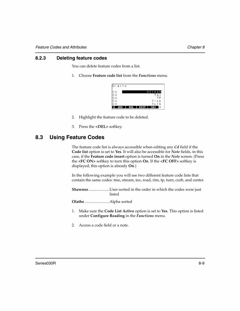
Feature Codes and Attributes Chapter 8
Series030R 8-9
8.2.3 Deleting feature codes
You can delete feature codes from a list.
1. Choose Feature code list from the Functions menu.
2. Highlight the feature code to be deleted.
3. Press the <DEL> softkey.
8.3 Using Feature Codes
The feature code list is always accessible when editing any Cd field if the Code list option is set to Yes. It will also be accessible for Note fields, in this case, if the Feature code insert option is turned On in the Note screen. (Press the <FC ON> softkey to turn this option On. If the <FC OFF> softkey is displayed, this option is already On.)
In the following example you will see two different feature code lists that contain the same codes: tree, stream, tax, road, rim, tp, turn, curb, and center.
Shawnee .....................User-sorted in the order in which the codes were just listed
Olathe .........................Alpha sorted
1. Make sure the Code List Active option is set to Yes. This option is listed under Configure Reading in the Functions menu.
2. Access a code field or a note.

Chapter 8 Feature Codes and Attributes
8-10 Series030R
3. When typing in a code field or a note, the Series030R searches for feature codes in the current list in the following manners. User-sorted lists access feature codes one letter at a time; while alpha-sorted lists can access letter combinations.
4. When the appropriate feature code is highlighted, press <Enter> and the code will be entered into the code field or note in which you are working.
Table 6: User-Sorted List vs. Alpha-Sorted List
Enter User-sorted list Alpha-sorted list
T(one letter)
The first feature code beginning with that letter is highlighted. The first feature code beginning with
that letter is highlighted.
TT(two identical letters)
Series030R searches for the next feature code in the list which begins with that letter.
Series030R searches for the next feature code that begin with those two letters. If no matches are found, the input screen from which the feature code list was accessed appears.
TR(two different letters)
Series030R searches for the first feature code in the list that begins with the second letter (“r” in this example).
Series030R searches for the next feature code that has those two letters at the beginning.

Feature Codes and Attributes Chapter 8
Series030R 8-11
8.4 Defining Attributes
Attributes are optionally defined as part of the feature code definition. Each feature code can have up to five attributes, each of which can have a user-defined name and a type of Alpha or Numeric.
1. When you add or edit a feature code, the following screen is displayed:
2. Enter in the Attributes field the number of attributes required for this code. Setting the number to 0 means you will not be prompted for attributes when the feature code is used. The screen changes to display the same number of Info fields as the number of attributes specified.
3. Select each Info field and change the name to the attribute required — the names entered here are the prompts that will display on the screen when a point is assigned this feature code.
4. Assign each attribute a type (Alpha or Numeric) using the <←> or <→> keys in the Type field. Alpha type attributes may be up to 16 characters long. Numeric type attributes up to 10 digits long, limited to ±9999999, and display up to three decimal places.
5. Press <Enter> to accept this definition, and then define any other feature codes desired.

Chapter 8 Feature Codes and Attributes
8-12 Series030R
8.5 Entering Attributes
Attributes values are entered when taking observations with applicable feature codes. Enter the feature code name in the usual way, by typing the first and second letter of the feature code, and then pressing <Enter>.
When the instrument reading is completed, press <Enter> or the <READ> softkey as usual to store the reading. The following screen is shown to allow entry of the attributes for the TREE feature code:
Once the appropriate attributes have been entered for the point, press <Enter> and all the attributes are stored in separate Note records after the observation. These Note records have a derivation code of AT (Attribute).
These notes can be printed, or the comms output format file can be modified using an appropriate program to produce a file suitable for direct input into a GIS or other asset management system.
Alternatively, your PC’s serial communications program can be used to create a DXF file that contains the attribute information for each point. This DXF file can be used for direct input into AutoCAD or GIS systems that read DXF format files, or it can again be modified by an appropriate conversion program.
NOTE For more information, refer to the documentation for the PC’s serial communication’s program.

Series030R 9-1
Chapter 9 Station Setup and Backsight
When you perform surveying tasks (such as, using Topography from the Survey menu), your Series030R needs information about your instrument location and backsight. You provide this information by establishing a station and performing a backsight observation.
9.1 Setting up a Station
If you have not previously set up an instrument station and attempted to take a reading, the following screen displays:
Enter instrument setup and station coordinate information in the following fields:
Stn ............................... Specifies the station point name. If you enter a name known to the Series030R, it fills in the coordinate fields with the point's coordinates; otherwise it sets the coordinate fields to Null (unknown).
North, East, Elev ....... Show the point's coordinates. You may change any or all of these values.
In this chapter
• Station setup
• Backsight observation
• Deriving station elevation

Chapter 9 Station Setup and Backsight
9-2 Series030R
Theo Ht.......................The theodolite height - the instrument's height above the ground point. Refer to the Basic Operation Manual to determine the instrument height mark.
Pressure ......................(available only if Atmos crn field is Yes when the job was setup) Should be set to the current barometric pressure. If the pressure is unknown, set the value to Null by pressing <SP>, then <Enter>.
Temperature...............(available only if Atmos crn field is Yes when the job was setup) Should be set to the current atmospheric temperature. If the temperature is unknown, set the value to Null by pressing <SP>, then <Enter>.
Cd ................................(for descriptive purposes only) A 16-character alphanumeric field. It may be left blank.
Press <Enter> to accept and store the station setup.
9.2 Observing a Backsight
Once you have entered station details, you should enter a backsight.
1. Enter the backsight point name in the BS pt field:
2. If the point is unknown, the Series030R displays this menu.
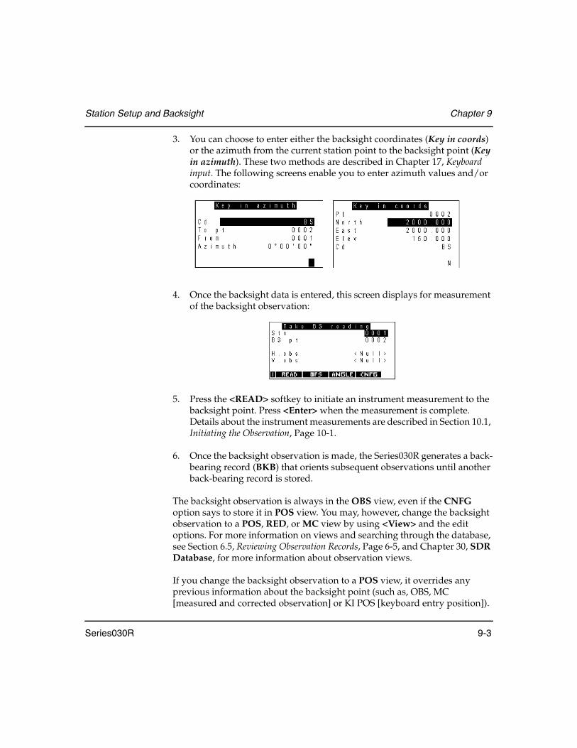
Station Setup and Backsight Chapter 9
Series030R 9-3
3. You can choose to enter either the backsight coordinates (Key in coords) or the azimuth from the current station point to the backsight point (Key in azimuth). These two methods are described in Chapter 17, Keyboard input. The following screens enable you to enter azimuth values and/or coordinates:
4. Once the backsight data is entered, this screen displays for measurement of the backsight observation:
5. Press the <READ> softkey to initiate an instrument measurement to the backsight point. Press <Enter> when the measurement is complete. Details about the instrument measurements are described in Section 10.1, Initiating the Observation, Page 10-1.
6. Once the backsight observation is made, the Series030R generates a back-bearing record (BKB) that orients subsequent observations until another back-bearing record is stored.
The backsight observation is always in the OBS view, even if the CNFG option says to store it in POS view. You may, however, change the backsight observation to a POS, RED, or MC view by using <View> and the edit options. For more information on views and searching through the database, see Section 6.5, Reviewing Observation Records, Page 6-5, and Chapter 30, SDR Database, for more information about observation views.
If you change the backsight observation to a POS view, it overrides any previous information about the backsight point (such as, OBS, MC [measured and corrected observation] or KI POS [keyboard entry position]).

Chapter 9 Station Setup and Backsight
9-4 Series030R
Any subsequent calculations using backsight coordinates will find the backsight observation and calculate the coordinates of the backsight point. Every observation has some error; this error will be reflected in the coordinates and will continue to grow in subsequent calculations.
9.2.1 Avoiding backsight
Backsight setup can be avoided, which is useful for testing or training. Press <Enter> when the Backsight point field is blank to eliminate backsight setup. A configuration prompt follows:
Press the <YES> softkey and then continue taking topographical observations. Horizontal angles stored are treated as azimuths with no orientation correction applied. This option is in effect until the next station is entered.
9.2.2 Averaging multiple backsights
Multiple backsights are supported by the topography program. When more than one known point or azimuth is observed, the resultant back-bearing corrections for each observation are averaged to generate a single back-bearing record. This back-bearing record orients subsequent observations.
The method for observing multiple backsights is described in Section 10.3, Averaging Multiple Observations, Page 10-10.
To use multiple backsights other than in topography (for example, when setting out), first use topography to measure the multiple backsights and generate the averaged back-bearing record. Exit topography and start the setting out program, confirming the existing orientation.

Station Setup and Backsight Chapter 9
Series030R 9-5
Technical note
The back-bearing record contains two fields: the calculated azimuth to a known point and the corresponding horizontal observation from the instrument to that point. The difference between these two values is used as the correction for subsequent horizontal observations to convert them to azimuths when reduced.
In the case of multiple backsights, the Series030R generates a back-bearing record with the point number of the most recently observed backsight and calculates a horizontal observation to go in the record.
NOTE This horizontal observation is not a value that has originated from the Series030R. It is a calculated value derived from averaging the back-bearing records. A correction reflecting the average correction derived from the individual backsights results.
If the Orient field in the Instrument option of the Functions menu is set to azimuth or zero, this information is transmitted to the instrument after the first backsight observation only.
A new back-bearing record is generated for each backsight observed. These records are internally weighted, so that observations to a third backsight point will be correctly averaged with the previous two backsight observations.
Chapter 9 Station Setup and Backsight
9-6 Series030R
9.3 Using a Backsight to Derive Station Elevation
If you set up the Series030R on a station point with an unknown (null) elevation, it calculates an elevation for your station when you observe a backsight point with a known elevation.
The backsight observation requires a slope distance measurement so that the elevation difference between the instrument and backsight target can be calculated.
The elevation field in the station record is automatically calculated and changed.
NOTE The derivation of station elevation is done only for the first backsight observation of a given station setup; subsequent backsight points' elevations are not used for station elevation determination.
The new station elevation is used for all subsequent calculations involving that station point's coordinates.
NOTE See Section 28.15, Setting Up Road Station, Page 28-44 for setting up a station and backsight for roading programs.
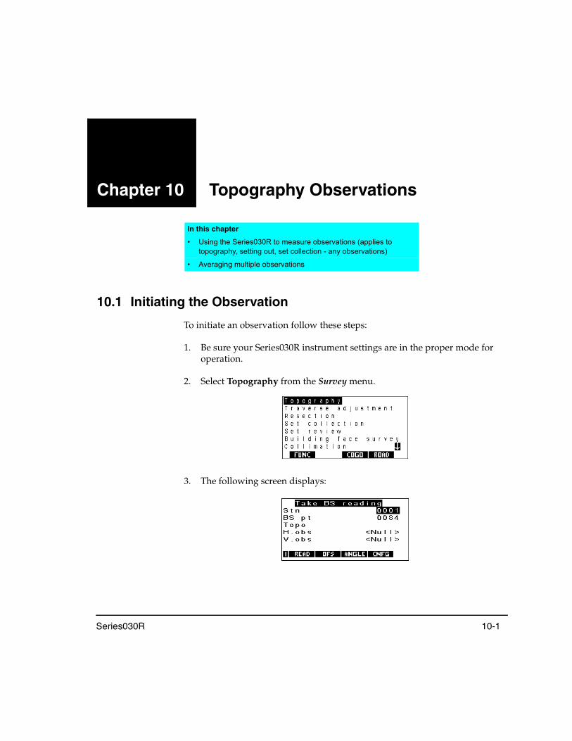
Series030R 10-1
Chapter 10 Topography Observations
10.1 Initiating the Observation
To initiate an observation follow these steps:
1. Be sure your Series030R instrument settings are in the proper mode for operation.
2. Select Topography from the Survey menu.
3. The following screen displays:
In this chapter
• Using the Series030R to measure observations (applies to topography, setting out, set collection - any observations)
• Averaging multiple observations

Chapter 10 Topography Observations
10-2 Series030R
4. Initiate a reading by pressing the <READ> softkey. The Series030R starts measuring and displays the following screen:
5. Enter values for the first three fields while the Series030R is measuring distance. The Series030R enters data for H.obs, V.obs, and S.Dist fields.
6. Store the observation by pressing <Enter>. The Series030R displays Input accepted and returns to the Take BS reading screen.
TIP As a shortcut, press the <READ> softkey to store the observation and initiate another reading.
Alternative actions can be performed with the following softkeys.
• Use the <OFS> softkey to access offset measurements (see the following section).
• Use the <ANGLE> softkey to initiate an angles-only (theodolite mode) reading.
• Use the <CNFG> softkey to access the Configure Reading screen (see Section 4.2.4, Configure reading, Page 4-6.)
Table 7: Read Screen Fields
Field Description
Cell The Code field is a 16-character field that describes the point being observed. If the Code lists active option in the Configuration menu is set to Yes, feature codes can be selected from this field. (See Feature codes and attributes, Chapter 8.) This is a quick and efficient method of entering feature codes from a pre-defined list.
Target Ht Enter the target height
Pt The Point name field is the name of the point being observed. Initially, this contains the next automatic point name allocated by the Series030R.

Topography Observations Chapter 10
Series030R 10-3
10.2 Taking Offset Observations
Three types of offset are available for topographical (and other) observations. These types are accessed by pressing the OFS softkey. The following screen will display:
<OFS> .........................Angle offset, where the horizontal angle is measured separately from the vertical angle and the distance.
<OFS-D> ....................Single-distance offset with direction.
<OFS-2D> ..................Two-distance offset, where two prisms are mounted on a rod and observed.
Pressing the appropriate softkey will initiate the offset reading. These offset types are explained in the following sections.
10.2.1 Angle offset observations
The angle offset observation is made with two readings. The first reading observes the vertical angle and distance and is observed on the prism. To take the second reading, the surveyor rotates the instrument until the target is in sight. The surveyor then observes the horizontal offset angle. The Series030R combines both readings into a single angle offset observation record.
1. From the Take reading screen, press the <OFS> softkey to view the offset softkeys.
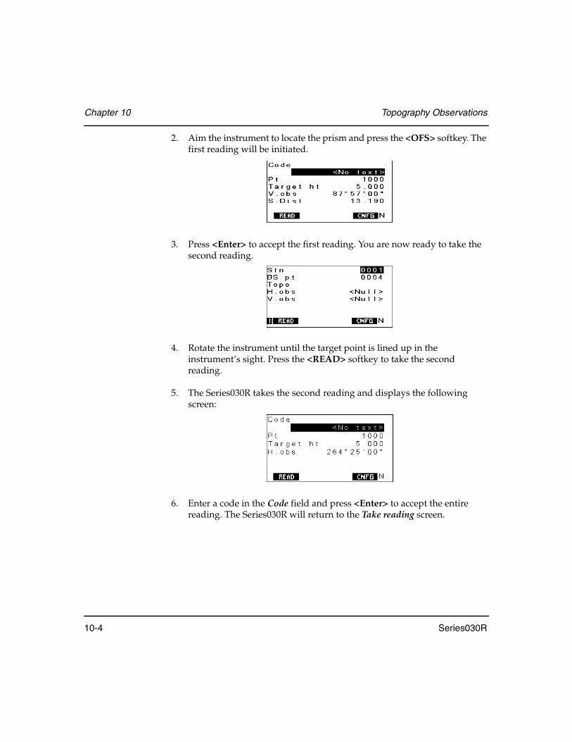
Chapter 10 Topography Observations
10-4 Series030R
2. Aim the instrument to locate the prism and press the <OFS> softkey. The first reading will be initiated.
3. Press <Enter> to accept the first reading. You are now ready to take the second reading.
4. Rotate the instrument until the target point is lined up in the instrument’s sight. Press the <READ> softkey to take the second reading.
5. The Series030R takes the second reading and displays the following screen:
6. Enter a code in the Code field and press <Enter> to accept the entire reading. The Series030R will return to the Take reading screen.
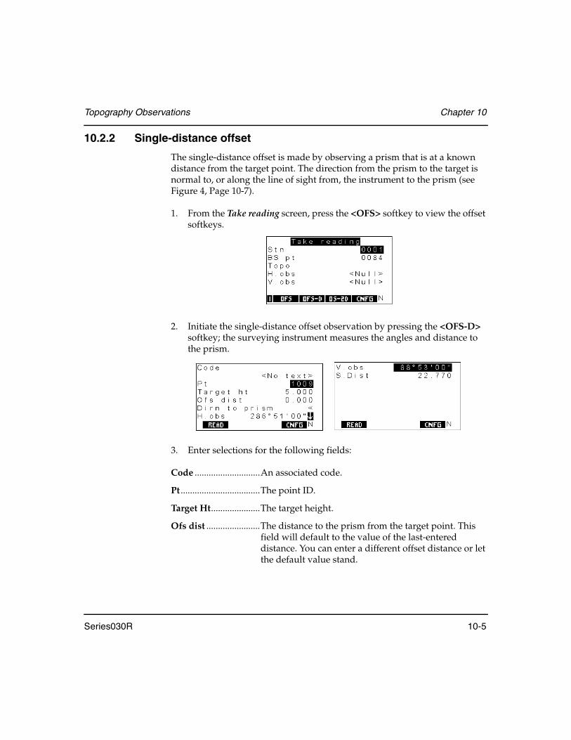
Topography Observations Chapter 10
Series030R 10-5
10.2.2 Single-distance offset
The single-distance offset is made by observing a prism that is at a known distance from the target point. The direction from the prism to the target is normal to, or along the line of sight from, the instrument to the prism (see Figure 4, Page 10-7).
1. From the Take reading screen, press the <OFS> softkey to view the offset softkeys.
2. Initiate the single-distance offset observation by pressing the <OFS-D> softkey; the surveying instrument measures the angles and distance to the prism.
3. Enter selections for the following fields:
Code ............................An associated code.
Pt ..................................The point ID.
Target Ht.....................The target height.
Ofs dist .......................The distance to the prism from the target point. This field will default to the value of the last-entered distance. You can enter a different offset distance or let the default value stand.

Chapter 10 Topography Observations
10-6 Series030R
Dirn to prism.............The direction to the prism from the target point as viewed by the instrument operator. Assign direction to the prism by using <←> or <→> to scroll through possible directions. Interpret the arrow direction from the perspective of the instrument operator as follows:
H.Obs..........................(information only) The horizontal observation angle.
V.obs............................(information only) The vertical observation angle.
S.Dist ..........................(information only) The slope distance.
4. Once the fields and the measurement are complete, press <Enter>.
5. The Series030R calculates the horizontal and vertical angles and slope distance to the target point, then it stores them in an observation record. The offset from the prism to the target point is assumed to be horizontal. A NOTE OS record (example shown below) is generated that shows the original measurements and the offset distance and direction used in the calculation. See Figure 5, Page 10-7.
Table 8: Arrows for Direction to Prism
Arrow Description
Right Prism is to the right of the target point
Down Prism is in front of the target point
Up Prism is behind the target point
Left Prism is to the left of the target point
NOTE OS100.00 90-00’00”23-00’00” OS 3.000Dirn <OBS F1 0005-1002S.Dist 100.045V.obs 90-00’00”H.obs24-43’06”POS TPNorth 90.878East41.835Elev 0.000Code 0

Topography Observations Chapter 10
Series030R 10-7
Figure 4: Direction to the prism from the target point
Figure 5: Horizontal/vertical angles and slope distance calculation
Point to be coordinated
Prism point
Instrument station
Behind
Target point
RightLeft
Instrument station

Chapter 10 Topography Observations
10-8 Series030R
10.2.3 Two-distance offset observation
The two-distance offset observation is made by using a rod that has two prisms attached. The rod extends a known distance past the end of each prism. Both prisms are observed, and the Series030R calculates the vector between them. The vector is then extrapolated the specified distance to find the target point’s coordinates.
Figure 6: Two-distance offset
1. Sight on the first prism (furthest from the target point).
2. From the Take reading screen, press <OFS> to view the offset softkeys.
3. Press <OSF-2D> to initiate the two-distance offset observation.
Prism 1
Prism 2
Offset distance
Target point
First
Second
Instrument
observation
observation
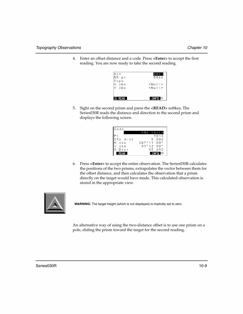
Topography Observations Chapter 10
Series030R 10-9
4. Enter an offset distance and a code. Press <Enter> to accept the first reading. You are now ready to take the second reading.
5. Sight on the second prism and press the <READ> softkey. The Series030R reads the distance and direction to the second prism and displays the following screen.
6. Press <Enter> to accept the entire observation. The Series030R calculates the positions of the two prisms, extrapolates the vector between them for the offset distance, and then calculates the observation that a prism directly on the target would have made. This calculated observation is stored in the appropriate view.
An alternative way of using the two-distance offset is to use one prism on a pole, sliding the prism toward the target for the second reading.
WARNING: The target height (which is not displayed) is implicitly set to zero.

Chapter 10 Topography Observations
10-10 Series030R
10.3 Averaging Multiple Observations
When you use the topography program to observe a previously observed point or a point already known to the Series030R, you are shown the difference between the observation and the observation expected by Series030R based on its data. For example, you may see a screen like the following, where an asterisk (*) indicates a value that exceeds the tolerances specified in the Tolerance menu.
Please refer to Figure 7 for more information about the values listed on the screen. The ∆SDist field shows the difference in slope distance AB and the distance AB'. The ∆Azmth field shows the difference between the azimuth from A to B and the azimuth to the observed point B'. The ∆Vang field (not illustrated) shows the difference between the expected and observed vertical angles. The Pt-Pt SDist field (not illustrated) displays the slope distance between B and B'.
Figure 7: Comparing previous data and current observation
A
B
B'
Coordinate the Series030Ralready knows
Actualobservedposition
Observation thatSeries030R expects
∆SDist
∆Azmth
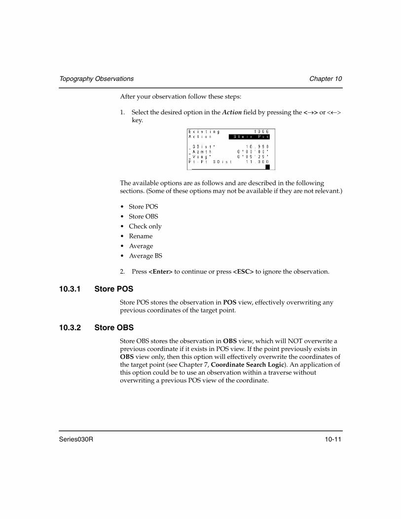
Topography Observations Chapter 10
Series030R 10-11
After your observation follow these steps:
1. Select the desired option in the Action field by pressing the <→> or <←> key.
The available options are as follows and are described in the following sections. (Some of these options may not be available if they are not relevant.)
• Store POS• Store OBS• Check only• Rename• Average• Average BS
2. Press <Enter> to continue or press <ESC> to ignore the observation.
10.3.1 Store POS
Store POS stores the observation in POS view, effectively overwriting any previous coordinates of the target point.
10.3.2 Store OBS
Store OBS stores the observation in OBS view, which will NOT overwrite a previous coordinate if it exists in POS view. If the point previously exists in OBS view only, then this option will effectively overwrite the coordinates of the target point (see Chapter 7, Coordinate Search Logic). An application of this option could be to use an observation within a traverse without overwriting a previous POS view of the coordinate.
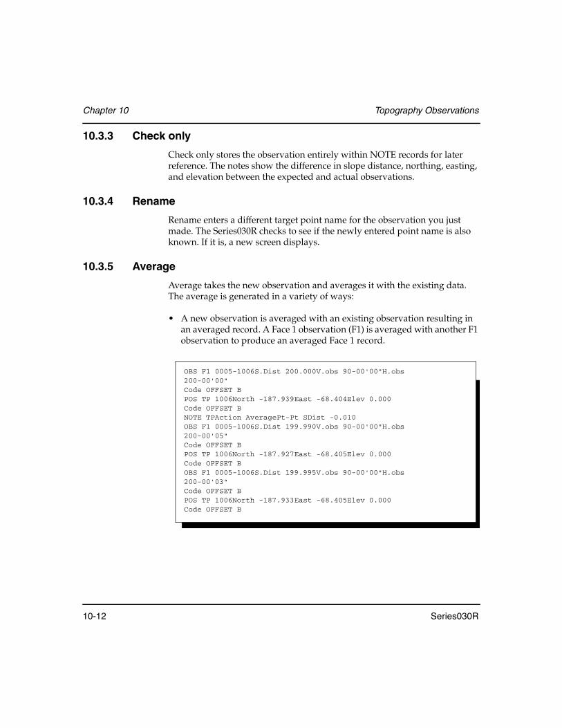
Chapter 10 Topography Observations
10-12 Series030R
10.3.3 Check only
Check only stores the observation entirely within NOTE records for later reference. The notes show the difference in slope distance, northing, easting, and elevation between the expected and actual observations.
10.3.4 Rename
Rename enters a different target point name for the observation you just made. The Series030R checks to see if the newly entered point name is also known. If it is, a new screen displays.
10.3.5 Average
Average takes the new observation and averages it with the existing data. The average is generated in a variety of ways:
• A new observation is averaged with an existing observation resulting in an averaged record. A Face 1 observation (F1) is averaged with another F1 observation to produce an averaged Face 1 record.
OBS F1 0005-1006S.Dist 200.000V.obs 90-00'00"H.obs200-00'00"Code OFFSET BPOS TP 1006North -187.939East -68.404Elev 0.000Code OFFSET BNOTE TPAction AveragePt-Pt SDist -0.010OBS F1 0005-1006S.Dist 199.990V.obs 90-00'00"H.obs 200-00'05"Code OFFSET BPOS TP 1006North -187.927East -68.405Elev 0.000Code OFFSET BOBS F1 0005-1006S.Dist 199.995V.obs 90-00'00"H.obs 200-00'03"Code OFFSET BPOS TP 1006North -187.933East -68.405Elev 0.000Code OFFSET B
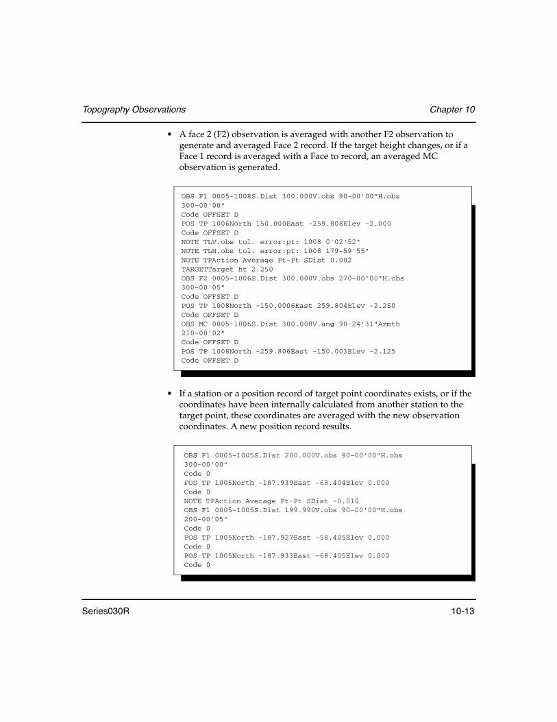
Topography Observations Chapter 10
Series030R 10-13
• A face 2 (F2) observation is averaged with another F2 observation to generate and averaged Face 2 record. If the target height changes, or if a Face 1 record is averaged with a Face to record, an averaged MC observation is generated.
• If a station or a position record of target point coordinates exists, or if the coordinates have been internally calculated from another station to the target point, these coordinates are averaged with the new observation coordinates. A new position record results.
OBS F1 0005-1008S.Dist 300.000V.obs 90-00'00"H.obs300-00'00"Code OFFSET DPOS TP 1006North 150.000East -259.808Elev -2.000Code OFFSET DNOTE TLV.obs tol. error:pt: 1008 0'02'52"NOTE TLH.obs tol. error:pt: 1008 179-59'55"NOTE TPAction Average Pt-Pt SDist 0.002TARGETTarget ht 2.250OBS F2 0005-1006S.Dist 300.000V.obs 270-00'00"H.obs 300-00'05"Code OFFSET DPOS TP 1008North -150.0006East 259.804Elev -2.250Code OFFSET DOBS MC 0005-1006S.Dist 300.008V.ang 90-24'31"Azmth210-00'02"Code OFFSET DPOS TP 1008North -259.806East -150.003Elev -2.125Code OFFSET D
OBS F1 0005-1005S.Dist 200.000V.obs 90-00'00"H.obs300-00'00"Code 0POS TP 1005North -187.939East -68.404Elev 0.000Code 0NOTE TPAction Average Pt-Pt SDist -0.010OBS F1 0005-1005S.Dist 199.990V.obs 90-00'00"H.obs 200-00'05"Code 0POS TP 1005North -187.927East -58.405Elev 0.000Code 0POS TP 1005North -187.933East -68.405Elev 0.000Code 0

Chapter 10 Topography Observations
10-14 Series030R
If the existing data for the target point is the result of an average calculation, the Series030R correctly weighs the values for subsequent averaging.
10.3.6 Average BS
Average BS creates a more accurate back-bearing record for orientation adjustments. To use this option, follow these steps:
1. Sight on a point with known coordinates in the SDR database. (This point may be the same point as the first backsight you observed, or it can be a different known point.)
2. Select Average BS and the Series030R calculates a new orientation correction based on the newly observed point. This correction is averaged with the existing correction. (A BKB record is generated with the first-observed backsight.)
This procedure can be repeated for any number of backsights (or multiple observation to the same backsight point or multiple observation to multiple backsight points). The Series030R handles the weighting for average calculations automatically where more than two orientation corrections are averaged.
NOTE If you are taking Face 2 observations and you average an observation as a backsight, you will not be prompted for a second face reading.

Series030R 11-1
Chapter 11 Set Collection
The Series030R provides a structured method for collecting multiple sets of observations from a station. The Series030R averages observations collected on Face 1 and Face 2 of the instrument and also averages multiple sets of observations. The resulting observations can be used either for traverse calculations or resection calculations.
11.1 Defining the Set Collection Method
The Series030R provides a mechanism for the structured collection of sets via a series of parameters. Set collection may be entirely “free-form” or may be completely driven through a pre-entered set of parameters and points.
When you select the Set collection option from the Survey menu, you are first asked to confirm the backsight orientation.
In this chapter
• Set collection options
• Observing sets
• Reviewing sets at the SETS, ALL, POINTS, SETS-POINTS and SETS-POINTS-FACES levels

Chapter 11 Set Collection
11-2 Series030R
Select the <OPTIONS> softkey in Set Collection to display the following screens.
The eight field settings on these screens determine how the Series030R does set collection. Each field is described briefly below, followed by a detailed description of each field.
Method .......................Controls the set collection method. The options are:
Number of H sets .....Controls how many sets of horizontal angles are collected. See Section 11.1.1, Number of H sets, Page 11-3
# dist rdgs...................Controls how many distance observations are made during each observational sighting. It can have any value from 0 to 9
Face order ...................Controls the switching between F1 and F2 during the collection of single as well as multiple sets. See Section 11.1.2, Face order, Page 11-3
Obs order ...................Specifies the order in which the Series030R prompts you to observe points when collecting individual sets. See Section 11.1.3, Obs order, Page 11-4
Return sight ...............(Direction method only) Specifies whether you wish to sight again on the first observed point in a set when the end of the set is reached
Table 9: Set Collection Methods
Method Description
Direction Several points are observed using the same instrument orientation.
Repetition A single angle is observed between two points several times using different instrument orientations.

Set Collection Chapter 11
Series030R 11-3
Pre-enter points ........Determines if you enter a list of points that you will observe, prior to observing any points in the set. See Section 11.1.4, Pre-enter points, Page 11-5
Recip Calc ..................Determines whether to perform reciprocal calculation. The options are Prompted, Always, or Never. See Section 11.1.5, Recip Calc, Page 11-5
11.1.1 Number of H sets
This field controls how many sets of horizontal angles are collected. This number is independent of whether both faces are being observed. For example, if the number of H sets is 3, and only F1 is being observed, three physical rounds of observations are required. If both F1 and F2 are observed, then six physical rounds of observations are required (one for each face for each set).
11.1.2 Face order
This field controls the switching between F1 and F2 during the collection of single as well as multiple sets. The selections on the Options screen assume you are interested in multiple sets.
The choices are as follows:
• F1 only• F2 only• F1F2/F1F2• F1F2/F2F1• F2F1/F2F1• F2F1/F1F2
Some selections show two sets, separated by a slash, indicating that both faces will be used. For example, F1F2/F2F1 specifies that, in the first set, observations will be made to points in the set beginning with Face 1 and then Face 2 of your instrument, and in the second set, you will reobserve the same points beginning with Face 2 and then Face 1 of the instrument. This pattern is repeated for subsequent sets (the third set will be collected in the same manner as the first, while the fourth set will be collected in the same manner as the second).

Chapter 11 Set Collection
11-4 Series030R
If you wish to observe only one set, taking first Face 1 then Face 2, you should choose either F1F2/F1F2 or F1F2/F2F1. (Since you are only collecting one set, ignore the second set specification)
11.1.3 Obs order
This field specifies the way the Series030R prompts you to observe points when collecting individual sets. The options are as follows:
Unprompted ..............Series030R will not prompt you at all and observations may be made in any order.You are not allowed to select pre-enter points if Unprompted is the Obs order option.
123...123.......................Series030R prompts for the second face of a set in exactly the same order as it prompted the first face. For example, if you select 123...123... and preenter points A, B, C, and D, you are prompted to observe points in the following order:
In this example, the face order was F1F2/F1F2 (or F1F2/F2F1).
123...321.......................Series030R prompts for the second face of a set be prompted in reverse order:
A,F1→B,F1→C,F1→D,F1→A,F2→B,F2→C,F2→D,F2
A,F1→B,F1→C,F1→D,F1→D,F2→C,F2→B,F2→A,F2

Set Collection Chapter 11
Series030R 11-5
11.1.4 Pre-enter points
When this field is Yes, the Series030R allows you to enter a list of points that you will observe, prior to observing any points in the set. The Series030R will use the list's order, in conjunction with the Obs order field, to prompt you for the next point to observe.
If this field is set to No, you will not be asked for the point names prior to observing the points. The Series030R will, however, intelligently guess which point you are observing based on the observations taken, and assist you by supplying the point name, code and target height, if required. This feature is active only for sets collected by direction.
11.1.5 Recip Calc
The Series030R can perform reciprocal calculations between a station and its backsight. These calculations can be performed in both normal topography and in set collection. The method to set for reciprocal calculation is slightly different for topography and set collection. Reciprocal calculation for set collection is discussed below. For information on reciprocal calculation for topography, see Section 4.2.4, Configure reading, Page 4-6.
NOTE The Recip Calc field shown by pressing the <CONFG> softkey on the read screen pertains to topography and does NOT affect set collection.
The options for reciprocal calculations in set collection are as follows:
Prompted....................You will receive a prompt every time a reading is taken to a point which could be used in a reciprocal calculation
Always ........................Performance of all possible reciprocal calculation is automatic; the user does not receive a prompt
Never...........................Series030R will not perform reciprocal calculations, even if one is possible, and the user receives no prompt

Chapter 11 Set Collection
11-6 Series030R
Notes are placed in the database when reciprocal calculations are performed. The first note is placed above the Stn and states Vert Recip Calc refined Stn ### Elev. The second note is placed above the BKB record and states Recip Calc used Stns #### & ####.
11.2 Observing Sets
After you define your set collection method, you can begin set collection.
11.2.1 Pre-entering points
If the Pre-enter points field was set to Yes, the initial screen is for entering the names of the points that will be observed during each set.
1. Enter the point names. The first point displayed is the station's backsight (B in this example).
2. Enter as many point names as you like; the list scrolls when you reach the bottom of the screen. If you make a mistake during entry, use the <↑> and <↓> keys to move to the incorrect entry, and then edit it in the usual manner.
3. To edit the list of entries use the following softkeys:
<INS> .........................Adds an extra point name in the list before the currently highlighted point.
<DEL>.........................Removes the currently highlighted point name.
<DEL ALL>................Deletes all point names.

Set Collection Chapter 11
Series030R 11-7
4. Once the list is complete, press the <Enter> key to start observations.
NOTE If at any time you want to leave the set collection procedure completely, press the <ESC> key. A prompt asks whether you want to leave set collection.
11.2.2 Making the observations
1. If you pressed <Enter> to continue with the collection of sets, the following screen displays. This screen's layout varies slightly depending on which collection method has been defined, but is similar to the following:
The set number in the top right of the screen is the count of sets observed so far from the station you are set up on. If you have requested point prompting, the To pt field shows you the point name to observe.
2. When the instrument is sighted correctly, press the <READ> softkey to initiate a reading. The standard observation screen will appear:
Set number
Point to observe

Chapter 11 Set Collection
11-8 Series030R
3. To change the Pt, Code, or Target ht fields, highlight the appropriate field and enter the new value. The Series030R fills in the data fields (H.obs, V.obs, and Dist) when the values are available. The information on this screen depends on what you set as the Obs Order:
4. If the Pre-enter points field is set to Yes, the Series030R will display the following screen once a set is complete.
If the Pre-enter points field is set to No, a face or a set is completed by pressing <Enter> at the Take reading screen.
Table 10: Obs Order Description
Obs Order Description
Unprompted If the Obs order field is Unprompted and you have observed this point before, the code, point name and target height are filled automatically. The Series030R determines whether the points are the same by checking to see if the new OBS distance is within 15 cm (<6") of the previous OBS distance. If this test passes, the Series030R compares the horizontal angle of the two observations to see whether they are within a certain tolerance. This tolerance is calculated based upon the distance of the observation; the longer the distance, the smaller the allowed tolerance. The angular tolerance is calculated to yield approximately 15 cm arc distance. If the horizontal test also passes, a similar angular test is performed on the vertical angle.
123...123 or 123...321
When the Obs order is 123...123 or 123...321, you are prompted for the next appropriate point name. The code and target height will be filled in if this point has been observed previously. To change these values, enter new ones.
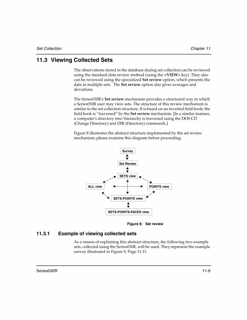
Set Collection Chapter 11
Series030R 11-9
11.3 Viewing Collected Sets
The observations stored in the database during set collection can be reviewed using the standard data review method (using the <VIEW> key). They also can be reviewed using the specialized Set review option, which presents the data in multiple sets. The Set review option also gives averages and deviations.
The Series030R's Set review mechanism provides a structured way in which a Series030R user may view sets. The structure of this review mechanism is similar to the set collection structure. It is based on an inverted field book; the field book is “traversed” by the Set review mechanism. [In a similar manner, a computer's directory tree/hierarchy is traversed using the DOS CD (Change Directory) and DIR (Directory) commands.]
Figure 8 illustrates the abstract structure implemented by the set review mechanism; please examine this diagram before proceeding.
Figure 8: Set review
11.3.1 Example of viewing collected sets
As a means of explaining this abstract structure, the following two example sets, collected using the Series030R, will be used. They represent the example survey illustrated in Figure 9, Page 11-11.
Survey
Set Review
SETS view
ALL view POINTS view
SETS-POINTS view
SETS-POINTS-FACES view

Chapter 11 Set Collection
11-10 Series030R
Example Set 1
After you have collected Face 1, the Series030R displays this prompt:
Example Set 2
Upon completion of this set, the following screen displays:
Set Face H.ang V.ang S.Dist
Set 1Face 1STNA0°0'00"90°00'00"100.000STNB45°00'00"90°00'00"141.420STNC90°00'00"90°00'00"100.000
Set Face H.ang V.ang S.Dist
Set 1,Face 2STNC270°00'00"270°00'00"100.000STNB225°00'00"270°00'00"141.420STNA180°00'00"270°00'00"100.000

Set Collection Chapter 11
Series030R 11-11
Using <OPTIONS>, change Face order to F1 only.
The azimuth from A to STN is 10°00'00".
Figure 9: Example survey
The first set is a “perfect” representation of the layout of the points A, B, C with respect to STN, while the second set contains inaccuracies for the purposes of illustrating the Set review mechanism to its fullest.
11.3.2 SETS level
The entire Set review structure is explained below using the two sets defined earlier.
There are two ways of reviewing sets:
• Review when you collect sets.• Use the Set review option in the Survey menu.
Set Face H.ang V.ang S.Dist
Set 2, Face 1(Only)STNA60°00'30"90°00'30"100.020STNB105°00'20"90°00'20"141.410
98.4808, 17.3648
A
B
C
STN
81.116, 115.8456
-17.3648, 98.4808
0, 0
N
Az 10°00’00”

Chapter 11 Set Collection
11-12 Series030R
The initial Set review display is illustrated below:
This display indicates all of the points observed during the collection of Set 1 from the STN station; it represents the SETS level (see Figure 8, Page 11-9 and Figure 9, Page 11-11).
Points observed in other sets obtained from STN are displayed by pressing the <→> and <←> arrow keys (see Figure 10, Page 11-13). For example, pressing the <→> key shows the points observed in Set 2.
NOTE Point C was not observed in Set 2.
Pressing the <←> key when the first collected set is displayed, or pressing the <→> key when the most recently collected set is displayed, results in this message:
From the SETS level, it is possible to travel in four directions:
<ALL> .........................Softkey takes you to the higher ALL level.

Set Collection Chapter 11
Series030R 11-13
<PTS> ........................Softkey takes you across to the equivalent POINTS level.
<Enter> .......................Key takes you down to the lower SETS-POINTS level.
<ESC> .........................Key exits Set review.
These levels are illustrated in Figure 10 and are described in the following sections.
Figure 10: Set review SETS view
11.3.3 ALL level
Press the <ALL> softkey on the SETS level to enter the ALL level -- the top of the set hierarchy. For the two example sets, this level looks like:
It indicates that two sets have been collected from the station (STN), and observations have been made to the points labeled A, B, and C within these sets.
From the ALL level you can proceed as shown in Figure 11, Page 11-14.
Surv
Set Review
<Enter>
SETS-POINTS View
Other SetsALL View
POINTS View
Other Sets
<ESC>
Leftarrow
Rightarrow
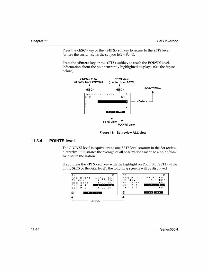
Chapter 11 Set Collection
11-14 Series030R
Press the <ESC> key or the <SETS> softkey to return to the SETS level (where the current set is the set you left -- Set 1).
Press the <Enter> key or the <PTS> softkey to reach the POINTS level. Information about the point currently highlighted displays. (See the figure below.)
Figure 11: Set review ALL view
11.3.4 POINTS level
The POINTS level is equivalent to one SETS level stratum in the Set review hierarchy. It illustrates the average of all observations made to a point from each set in the station.
If you press the <PTS> softkey with the highlight on Point B in SET1 (while in the SETS or the ALL level), the following screens will be displayed:
<Enter>
POINTS View
POINTS ViewSETS View
<ESC><ESC>
POINTS View(if enter from POINTS)
SETS View(if enter from SETS)
<FNC>
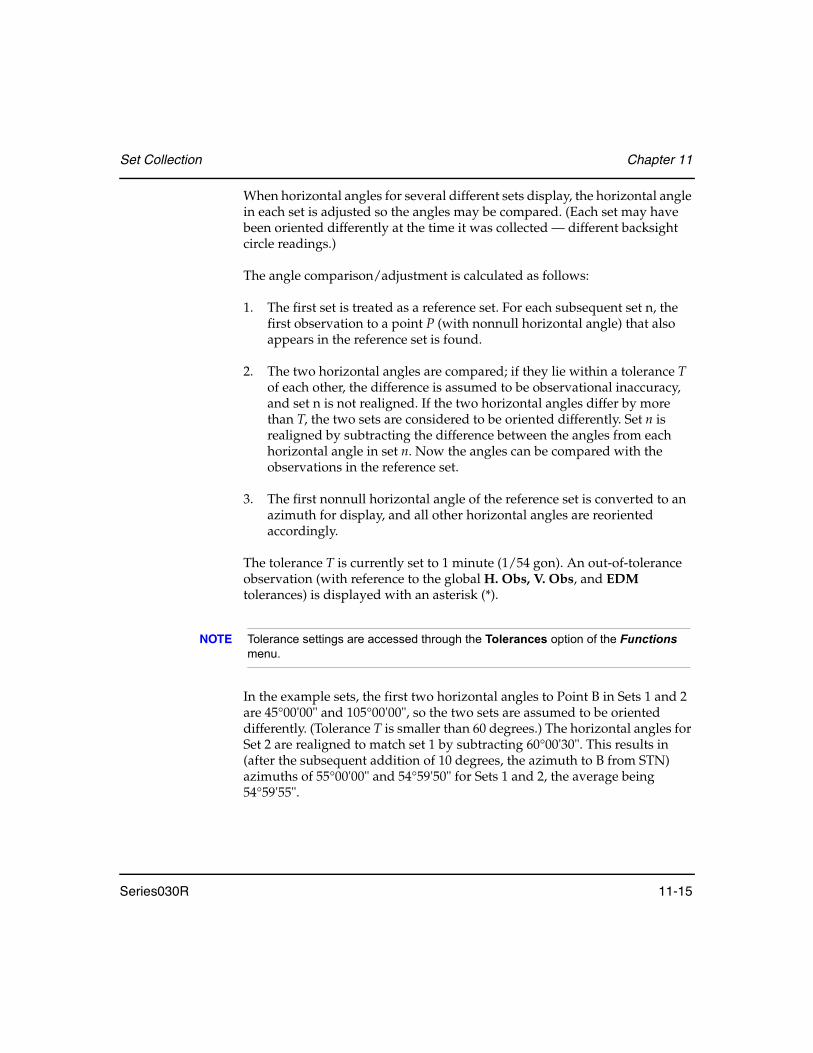
Set Collection Chapter 11
Series030R 11-15
When horizontal angles for several different sets display, the horizontal angle in each set is adjusted so the angles may be compared. (Each set may have been oriented differently at the time it was collected — different backsight circle readings.)
The angle comparison/adjustment is calculated as follows:
1. The first set is treated as a reference set. For each subsequent set n, the first observation to a point P (with nonnull horizontal angle) that also appears in the reference set is found.
2. The two horizontal angles are compared; if they lie within a tolerance T of each other, the difference is assumed to be observational inaccuracy, and set n is not realigned. If the two horizontal angles differ by more than T, the two sets are considered to be oriented differently. Set n is realigned by subtracting the difference between the angles from each horizontal angle in set n. Now the angles can be compared with the observations in the reference set.
3. The first nonnull horizontal angle of the reference set is converted to an azimuth for display, and all other horizontal angles are reoriented accordingly.
The tolerance T is currently set to 1 minute (1/54 gon). An out-of-tolerance observation (with reference to the global H. Obs, V. Obs, and EDM tolerances) is displayed with an asterisk (*).
NOTE Tolerance settings are accessed through the Tolerances option of the Functions menu.
In the example sets, the first two horizontal angles to Point B in Sets 1 and 2 are 45°00'00" and 105°00'00", so the two sets are assumed to be oriented differently. (Tolerance T is smaller than 60 degrees.) The horizontal angles for Set 2 are realigned to match set 1 by subtracting 60°00'30". This results in (after the subsequent addition of 10 degrees, the azimuth to B from STN) azimuths of 55°00'00" and 54°59'50" for Sets 1 and 2, the average being 54°59'55".

Chapter 11 Set Collection
11-16 Series030R
NOTE Angles are averaged within their sets before averages between sets are computed; observations are not weighted individually.
From this POINTS level you may proceed as indicated in Figure 12:
Figure 12: Set review POINTS view
1. Press the <ESC> key to exit Set review.
2. Press the <ALL> softkey to view the ALL level.
3. Press the <SETS> softkey to enter the SETS display. The current set depends on which set is highlighted when you press the <SETS> softkey. The cursor in the SETS level is placed over the current point (B).
Exit
<ESC>
SETS View
ALL ViewSETS-POINTS View
Other pointsin POINTS View
Highlight setpress <Enter>
Other pointsin POINTS View
Left arrow key Right arrow key
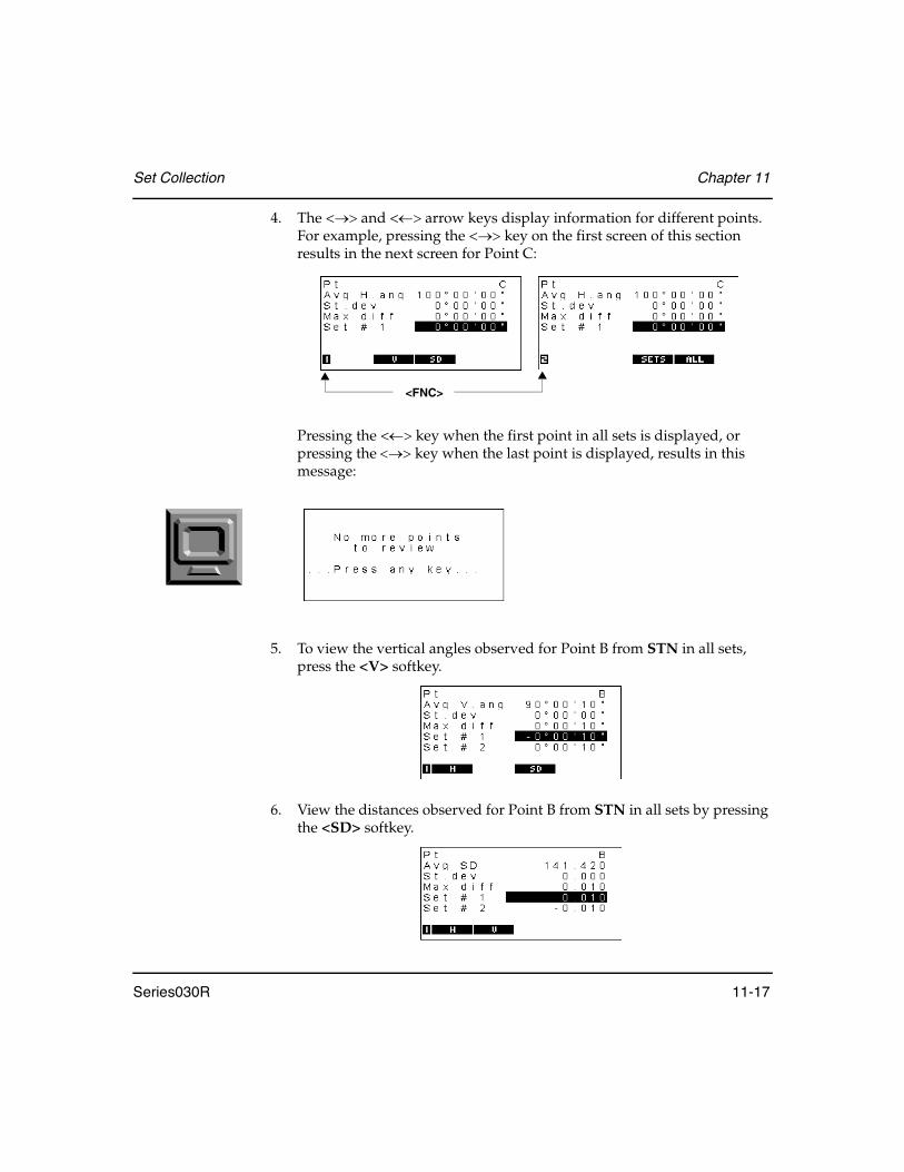
Set Collection Chapter 11
Series030R 11-17
4. The <→> and <←> arrow keys display information for different points. For example, pressing the <→> key on the first screen of this section results in the next screen for Point C:
Pressing the <←> key when the first point in all sets is displayed, or pressing the <→> key when the last point is displayed, results in this message:
5. To view the vertical angles observed for Point B from STN in all sets, press the <V> softkey.
6. View the distances observed for Point B from STN in all sets by pressing the <SD> softkey.
<FNC>

Chapter 11 Set Collection
11-18 Series030R
Press the <Enter> key to view the SET-POINTS level. The current point is B, and the current set is determined by the cursor position at the time you press the <Enter> key.
11.3.5 SETS-POINTS level
Use SETS-POINTS level to view the various observations to a point in a specific set. (Typically, but not necessarily, these observations are one F1 and one F2.) If you are in Set 1, Point B, at the SETS review level, the SETS-POINTS level is accessed by pressing <Enter> The following screens display at this level:
• The third and fourth lines list the horizontal angles of each observation made to Point B in Set 1.
• The fifth line gives the average (represented as an F1 observation) of the horizontal observations made to the Point B in Set 1.
• The sixth line gives the maximum difference between the average and the individual horizontal observations.
• The seventh line gives the difference between the average from the fifth line and the average over all sets (Sets 1 and 2).
If more than two observations to a point occur within a set, the fields will scroll.
Return sights are displayed independently of initial sights to the reference point. The way in which return sights are isolated is described in Section 11.3.7, Special cases, Page 11-22.
<FNC>

Set Collection Chapter 11
Series030R 11-19
In the SETS-POINTS level, you may proceed as indicated in Figure 13:
Figure 13: Set review SETS-POINTS view
• The <ESC> key takes you up the hierarchy to either the SETS level or the POINTS level, depending on from which of these you came.
• The <V> and <SD> softkeys show information equivalent to the above display, but for vertical angles and slope distances respectively.
• The <→> and <←> arrows give data on points within the current set.
SETS View
<ESC>
Prior Sets
Subsequent SetsSETS-POINTS-FACES View
Other pointsin SETS-POINTS View
Highlight a face
press <Enter>
Left arrow key Right arrow key
if entered from SETSPOINTS View
<ESC>
if entered from POINTS
observation and
Other pointsin SETS-POINTS View

Chapter 11 Set Collection
11-20 Series030R
• The <← SET> and <SET→> softkeys display previously and subsequently collected sets. If the current point appears in the set you move to, that point will be highlighted. Otherwise, the first point in the set is highlighted. If the <← SET> key is pressed when the first set collected is displayed, or the <SET→ > key is pressed when the last set collected is displayed, the following message appears:
• Press <Enter> to invoke the Set review hierarchy’s lowest level, which gives a SETS-POINTS-FACES display (a complete raw observation).

Set Collection Chapter 11
Series030R 11-21
11.3.6 SETS-POINTS-FACES level
Highlight the F1 observation in the previous display and press <Enter>:
From this level you can proceed as shown in Figure 14.
Figure 14: Set review SETS-POINTS-FACES view
• Press the <← PTS> and <PTS→> softkey to display raw observations of previous and subsequent points within the current set:
SETS-POINTS View
<ESC>
Other faces inSETS-POINTS-FACES View
Left arrow key Right arrow key
Prior Sets
Subsequent Sets
Prior Points
Subsequent Points
Other faces inSETS-POINTS-FACES View
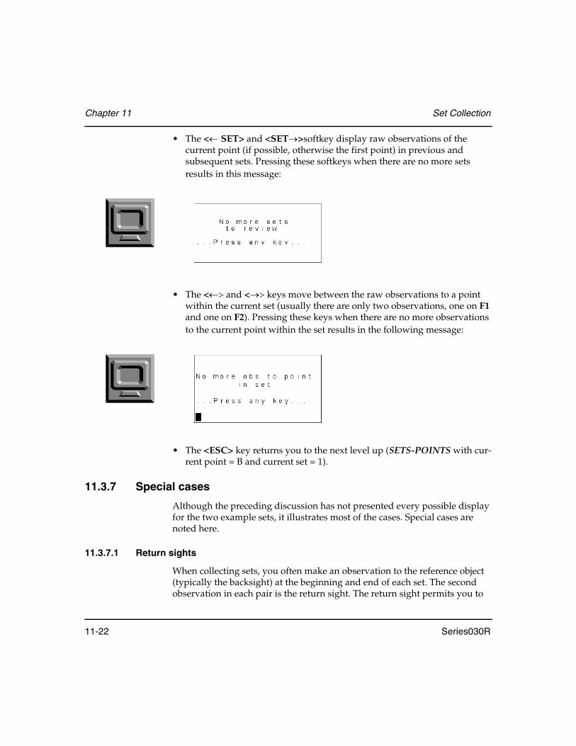
Chapter 11 Set Collection
11-22 Series030R
• The <← SET> and <SET→>softkey display raw observations of the current point (if possible, otherwise the first point) in previous and subsequent sets. Pressing these softkeys when there are no more sets results in this message:
• The <←> and <→> keys move between the raw observations to a point within the current set (usually there are only two observations, one on F1 and one on F2). Pressing these keys when there are no more observations to the current point within the set results in the following message:
• The <ESC> key returns you to the next level up (SETS-POINTS with cur-rent point = B and current set = 1).
11.3.7 Special cases
Although the preceding discussion has not presented every possible display for the two example sets, it illustrates most of the cases. Special cases are noted here.
11.3.7.1 Return sights
When collecting sets, you often make an observation to the reference object (typically the backsight) at the beginning and end of each set. The second observation in each pair is the return sight. The return sight permits you to

Set Collection Chapter 11
Series030R 11-23
distribute any return error (the difference in horizontal angle between the two reference observations) over the entire set, thus removing errors due to inaccuracies in the circle.
When you review a set containing a return sight, the horizontal angles have been adjusted for return error (before any other adjustment of the set takes place). The return sight appears as a separate entry in the hierarchy. For example, a set containing observations to points A, B, C and D, followed by a return sight to A, displays the POINTS level like this:
All levels of the Set review hierarchy have return error distributed, with the exception of the lowest raw observation level.
11.3.7.2 GOOD and BAD Sets
The Series030R permits you to mark a set as BAD if it contains inaccurate data or incorrect point identifier(s). Whenever an averaged set (MC records) is produced, BAD sets are omitted from the averaging process. An averaged set is produced:
• Each time a set collection session is completed• Each time a set is marked BAD• Each time a BAD set is remarked GOOD
The Set review mechanism permits the general reviewing of collected sets, with particular emphasis on the identification of sets that contain erroneous or out-of-tolerance observations. Sets that ought to be marked BAD are identified so you may evaluate whether they will corrupt subsequent calculations (such as a traverse).
Use the <BAD> softkey to mark a set BAD at the SETS level. A BAD set is displayed with an asterisk (*).
A← → B← → C← → D← → A1A1 denotes the return sight
Chapter 11 Set Collection
11-24 Series030R
Once a set is marked BAD, it is no longer included in any averaging calculations. Averages, standard deviations, and so on, that appears in the POINTS and SETS-POINTS levels of the Set review hierarchy do not take BAD sets into account. Basic information for BAD sets still appears, including the differences between BAD sets and the new averages.
You can mark a set that you suspect of interfering with the averages as BAD and then examine how the averages change. If you determine that the suspected set does not change the averages by an inordinate amount (if at all), change it back to GOOD by using the <GOOD> softkey.
NOTE If you change the marking of any sets, a new series of averaged MCs is output to the database at the end of the Set review session.
NOTE A set that has been obtained from comms input is available for further set collection, set review, or resection.
11.3.7.3 Collimation Correction
Collimation correction is applied to every level above the lowest (“raw observation”) level in the Set review hierarchy. Therefore, all angles displayed in Set review have collimation correction applied except in the SETS-POINTS-FACES level.
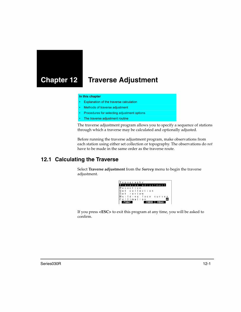
Series030R 12-1
Chapter 12 Traverse Adjustment
The traverse adjustment program allows you to specify a sequence of stations through which a traverse may be calculated and optionally adjusted.
Before running the traverse adjustment program, make observations from each station using either set collection or topography. The observations do not have to be made in the same order as the traverse route.
12.1 Calculating the Traverse
Select Traverse adjustment from the Survey menu to begin the traverse adjustment.
If you press <ESC> to exit this program at any time, you will be asked to confirm.
In this chapter
• Explanation of the traverse calculation
• Methods of traverse adjustment
• Procedures for selecting adjustment options
• The traverse adjustment routine

Chapter 12 Traverse Adjustment
12-2 Series030R
12.1.1 Starting point
The Series030R first asks for the point name of the first station in the traverse:
Enter the point name of the first station. The Series030R looks at the observations from that station and presents the route of the traverse as far as it can determine:
The Series030R presents you with a complete list of stations on your traverse route, until one of the following conditions is present:
• No further stations observed• More than one foresight station observed (for example, a branch was in
the route)• A station with known coordinates (for example, a POS KI keyboard input
position record exists for the point); such a station closes the traverse• An observation to a point that has a POS record with known coordinates
closes the traverse• A loop back to the first station of the traverse• The maximum number of traverse stations that the Series030R can handle
(200) has been exceeded

Traverse Adjustment Chapter 12
Series030R 12-3
12.1.2 Route
Press <Enter> if the route is complete. Otherwise, enter the next station's point name in the traverse route. The Series030R will find more stations to add to the route if applicable.
Use <↑> and <↓> to move around the list. If you change a point name, the Series030R discards the subsequent route and searches for a new one starting from the newly entered point.
12.1.3 Backsight and foresight azimuths
Once you accept the route, the Series030R asks you for details about the backsight and foresight azimuths to give angular control in the traverse calculation:
The Series030R presents suitable defaults for BS (backsight) and FS (foresight) points and azimuths.
The following rules apply to the specification of BS and FS azimuths:
• Neither a BS or FS azimuth is compulsory. However, if you do not have both, an angular close is not done (the subsequent ∆Ang result field in the Precision screen will be null). An angular adjustment cannot be done.
• Enter the azimuths directly or enter point names (see Section 17.2, Enter-ing Known Azimuths, Page 17-2). The Series030R calculates azimuths for you.
• A FS azimuth may not be specified unless there is a BS azimuth.
Press <Enter> to accept these default values or enter new values.

Chapter 12 Traverse Adjustment
12-4 Series030R
12.1.4 Traverse calculation
If you press the <Enter> key from the Traverse Orientation screen, the Series030R will calculate the precision of the traverse and display the results:
NOTE In the computation of the traverse closure, and in any subsequent traverse adjustment, the observations in both directions for any traverse leg are averaged to give the best values for that traverse leg. This also applies to observed vertical angles where a slope distance has not actually been measured in one direction; the average of the vertical angles in both directions are used in the computations.
Ang ..............................Angular closure error
Dist ..............................Horizontal closure distance
Precision .....................Precision of the traverse as a ratio of the total horizontal distance traversed to the closure distance
North...........................Closure distance in Northing coordinates
East ..............................Closure distance in Easting coordinates
Elev..............................Closure distance in elevation
NOTE If insufficient data was available to calculate the distance closure (for example, any leg of the traverse without distance information), the Series030R reports only an angular closure.

Traverse Adjustment Chapter 12
Series030R 12-5
12.2 Storing and Viewing Traverse Data
If you press the <STORE> softkey from the Results screen, the precision results, closure notes, traverse route, and BS and FS details are stored in the database as note records. Once the <STORE> softkey is pressed, an Input accepted message appears and the <STORE> softkey disappears.
You can press <FNC> + <VIEW> to review records in the traverse. The following screen displays:
Press <ESC> to return to the previous screen, the Traverse precision screen.
12.3 Adjusting the Traverse
When a traverse adjustment is initiated, the following screen displays:
Ang .................................................Angular closure error
Dist .................................................Horizontal closure distance

Chapter 12 Traverse Adjustment
12-6 Series030R
Precision ........................................Precision of the traverse as a ratio of the total horizontal distance traversed to the closure distance
North..............................................Closure distance in Northing coordinates
East .................................................Closure distance in Easting coordinates
Elev.................................................Closure distance in elevation
Adjustment options should be set before initiating the traverse adjust.
12.3.1 Adjustment options
Before starting the coordinate adjustment, press the <OPTIONS> softkey to specify the methods of coordinate, angular, and elevation adjustment.
Use the <←> or <→> keys to select the following options and then press <Enter> to accept your selection.
Method .......................................... Select the Compass or Transit coordinate adjustment method (see Section 12.3.1.1, Coordinate adjustment, Page 12-7).
Angular.......................................... Select Weighted, Linear, or None (see Section 12.3.1.2, Angular adjustment, Page 12-8).
Elev................................................. Select Weighted, Linear, or None (see Section 12.3.1.3, Elevation adjustment, Page 12-8)
Report angle adjust ..................... Select Yes or No to specify whether or not to display the updated closure and traverse precision details after the angular adjustment, but before the coordinate adjustment. The displayed angular closure after the angular adjustment is always zero.

Traverse Adjustment Chapter 12
Series030R 12-7
12.3.1.1 Coordinate adjustment
Two coordinate adjustment methods are available: Compass (or Bowditch) rule and Transit rule.
Compass rule formula
The Compass rule distributes the coordinate error in proportion to the length of the traverse lines.
Where: L = length of the traverse line to the pointTL = sum of the traverse line lengths
Transit rule formula
The Transit rule distributes the coordinate error in proportion to the northing and easting ordinates of each traverse line.
Where: ∆N =change in northing for the traverse line∆E =change in easting for the traverse lineΣ∆N =sum of the absolute value of all the changes in northings of all the traverse linesΣ∆E =sum of the absolute value of all the changes in eastings of all the traverse lines
Northing adjustment LTL------- closure×= north
Easting adjustment LTL------- closure×= east
Northing adjustment ∆N∆N∑
------------------ closure×= north
Easting adjustment ∆N∆N∑
------------------ closure×= east

Chapter 12 Traverse Adjustment
12-8 Series030R
12.3.1.2 Angular adjustment
Three angular adjustment options are available:
Weighted ....................Any angular closure is distributed among the angles of the traverse route based on the sum of the inverses of the forward and back traverse line lengths at each angle. The backsight and foresight lines are considered to have infinite lengths for the purposes of this weighting computation.
Linear ..........................Any angular closure is distributed evenly among the angles of the traverse route.
None............................No angular adjustment is carried out.
12.3.1.3 Elevation adjustment
Three elevation adjustment options are available:
Weighted ....................Any closure in the elevations is distributed in proportion to the length of the traverse line leading to the point (like the Compass rule used in the coordinate adjustment).
Linear ..........................Any closure in the elevations is distributed evenly in each leg of the traverse route.
None............................No elevation adjustment is carried out.
12.3.2 Starting the adjustment
To start the traverse adjustment, select the <ADJUST> softkey or press <Enter>. This softkey appears only if the coordinate closure is not null.
adjustment∠
1todist--------------- 1
fromdist----------------------+
1todist--------------- 1
fromdist----------------------+
∑--------------------------------------------------------- closure∠×=

Traverse Adjustment Chapter 12
Series030R 12-9
Angular adjustments are carried out first. If the Report angle adjust field was set to Yes in the Options screen, a report of the updated closure and traverse precision details displays. This display is the same as the initial traverse calculation display except that the angular closure is always zero.
The <STORE> softkey will store the displayed information in a NOTE record.
To continue with the coordinate adjustment (and elevation adjustment if selected), select the <ADJUST> softkey again or press <Enter>. When the traverse adjustment is complete the adjusted coordinates are stored as position records with an AJ (Adjusted by Traverse) derivation code. After coordinates are stored, the Series030R returns to the Survey menu.
As the Series030R uses the latest point coordinates in its calculations, the adjusted traverse points will be used for calculations.
Coordinates for sideshots from an adjusted traverse station are updated automatically by the coordinate shift applied to the traverse station coordinates.
NOTE While the sideshot point coordinates are updated automatically by the coordinate shift applied to the adjusted traverse station, any slight change in orientation at the traverse station due to an angular adjustment is not applied.


Series030R 13-1
Chapter 13 Building Face Survey
The building face program allows points on both vertical and nonvertical planes to be coordinated by angle-only observations. The primary use of the building face program is to pick up details of a building where the prism cannot be placed.
The building face is defined by observing three accessible points on the building or by entering their known coordinates. Angle-only observations are then made and the Series030R calculates and stores the coordinates of the intersection of the angle observation with the plane.
13.1 Defining the Building Face
1. Select the Building face survey option from the Survey menu to begin.
2. The Series030R will display the following screen:
In this chapter
• Coordination of points in a vertical plane using single angle-only observations
• Building face surveys in nonvertical planes
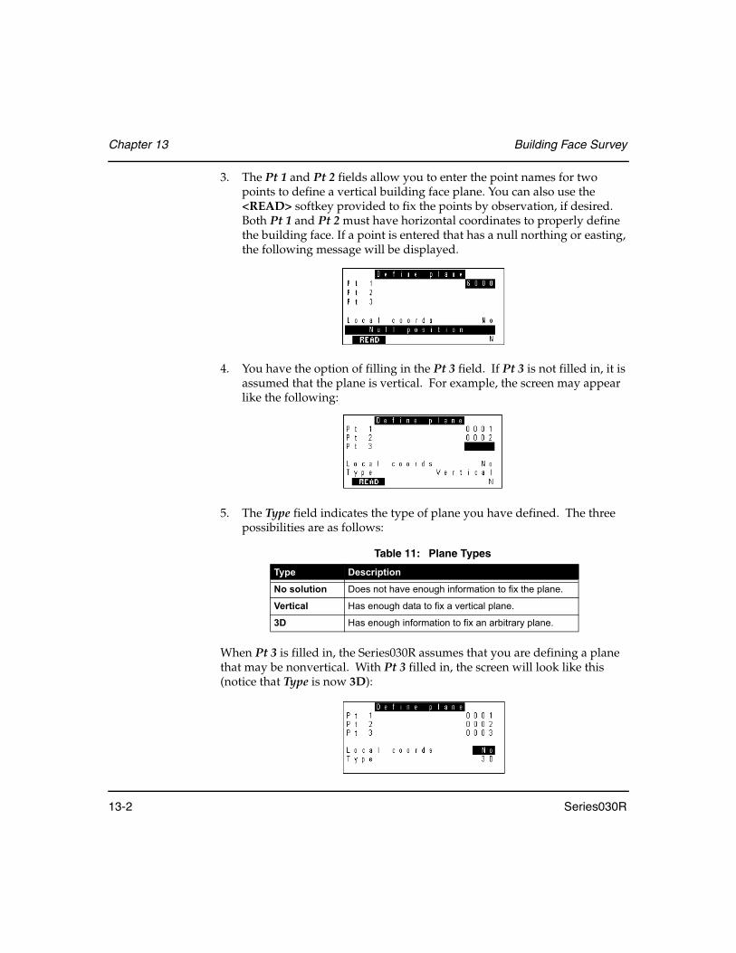
Chapter 13 Building Face Survey
13-2 Series030R
3. The Pt 1 and Pt 2 fields allow you to enter the point names for two points to define a vertical building face plane. You can also use the <READ> softkey provided to fix the points by observation, if desired. Both Pt 1 and Pt 2 must have horizontal coordinates to properly define the building face. If a point is entered that has a null northing or easting, the following message will be displayed.
4. You have the option of filling in the Pt 3 field. If Pt 3 is not filled in, it is assumed that the plane is vertical. For example, the screen may appear like the following:
5. The Type field indicates the type of plane you have defined. The three possibilities are as follows:
When Pt 3 is filled in, the Series030R assumes that you are defining a plane that may be nonvertical. With Pt 3 filled in, the screen will look like this (notice that Type is now 3D):
Table 11: Plane Types
Type Description
No solution Does not have enough information to fix the plane.
Vertical Has enough data to fix a vertical plane.
3D Has enough information to fix an arbitrary plane.
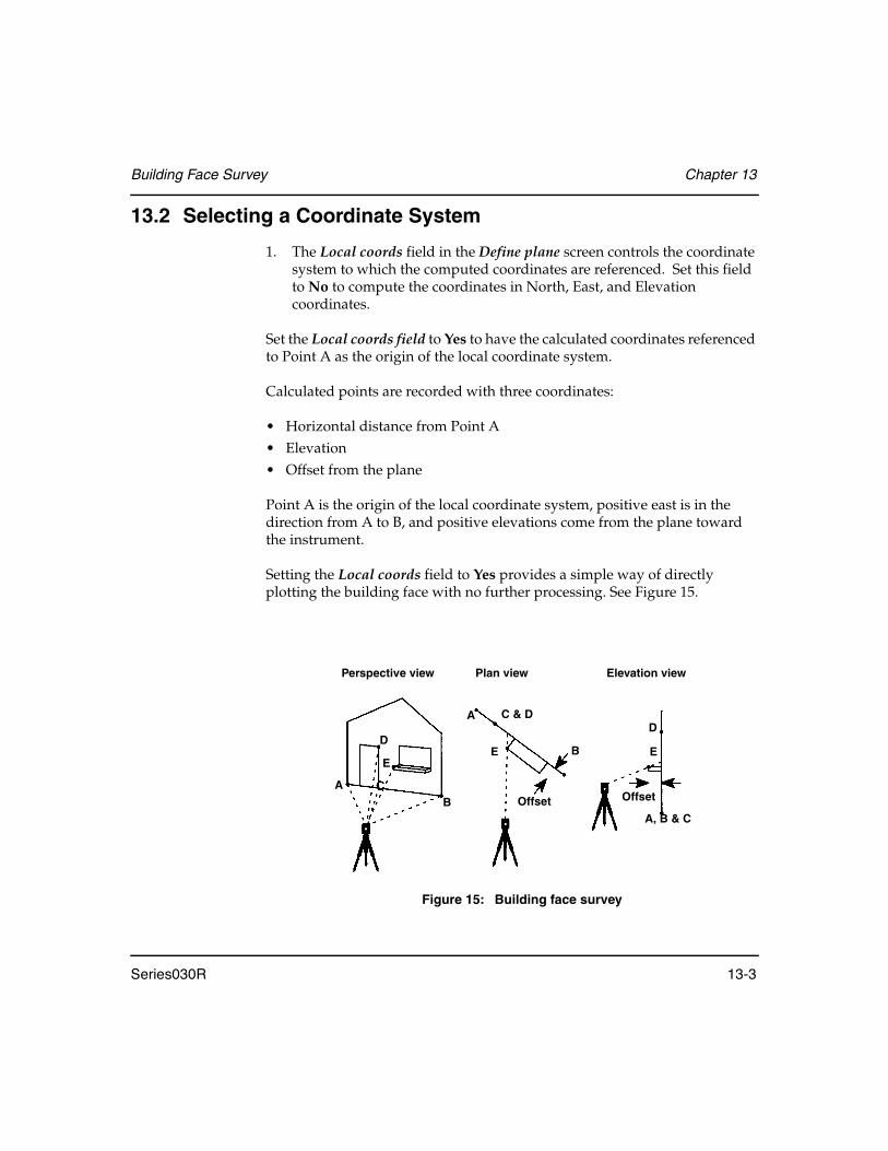
Building Face Survey Chapter 13
Series030R 13-3
13.2 Selecting a Coordinate System
1. The Local coords field in the Define plane screen controls the coordinate system to which the computed coordinates are referenced. Set this field to No to compute the coordinates in North, East, and Elevation coordinates.
Set the Local coords field to Yes to have the calculated coordinates referenced to Point A as the origin of the local coordinate system.
Calculated points are recorded with three coordinates:
• Horizontal distance from Point A• Elevation• Offset from the plane
Point A is the origin of the local coordinate system, positive east is in the direction from A to B, and positive elevations come from the plane toward the instrument.
Setting the Local coords field to Yes provides a simple way of directly plotting the building face with no further processing. See Figure 15.
Figure 15: Building face survey
Perspective view Plan view Elevation view
A C & D
E
Offset
B
A
B
D
E
A, B & C
D
E
Offset
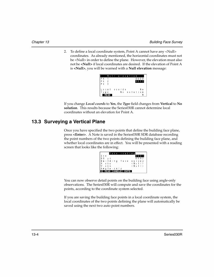
Chapter 13 Building Face Survey
13-4 Series030R
2. To define a local coordinate system, Point A cannot have any <Null> coordinates. As already mentioned, the horizontal coordinates must not be <Null> in order to define the plane. However, the elevation must also not be <Null> if local coordinates are desired. If the elevation of Point A is <Null>, you will be warned with a Null elevation message:
If you change Local coords to Yes, the Type field changes from Vertical to No solution. This results because the Series030R cannot determine local coordinates without an elevation for Point A.
13.3 Surveying a Vertical Plane
Once you have specified the two points that define the building face plane, press <Enter>. A Note is saved in the Series030R SDR database recording the point numbers of the two points defining the building face plane, and whether local coordinates are in effect. You will be presented with a reading screen that looks like the following:
You can now observe detail points on the building face using angle-only observations. The Series030R will compute and save the coordinates for the points, according to the coordinate system selected.
If you are saving the building face points in a local coordinate system, the local coordinates of the two points defining the plane will automatically be saved using the next two auto point numbers.
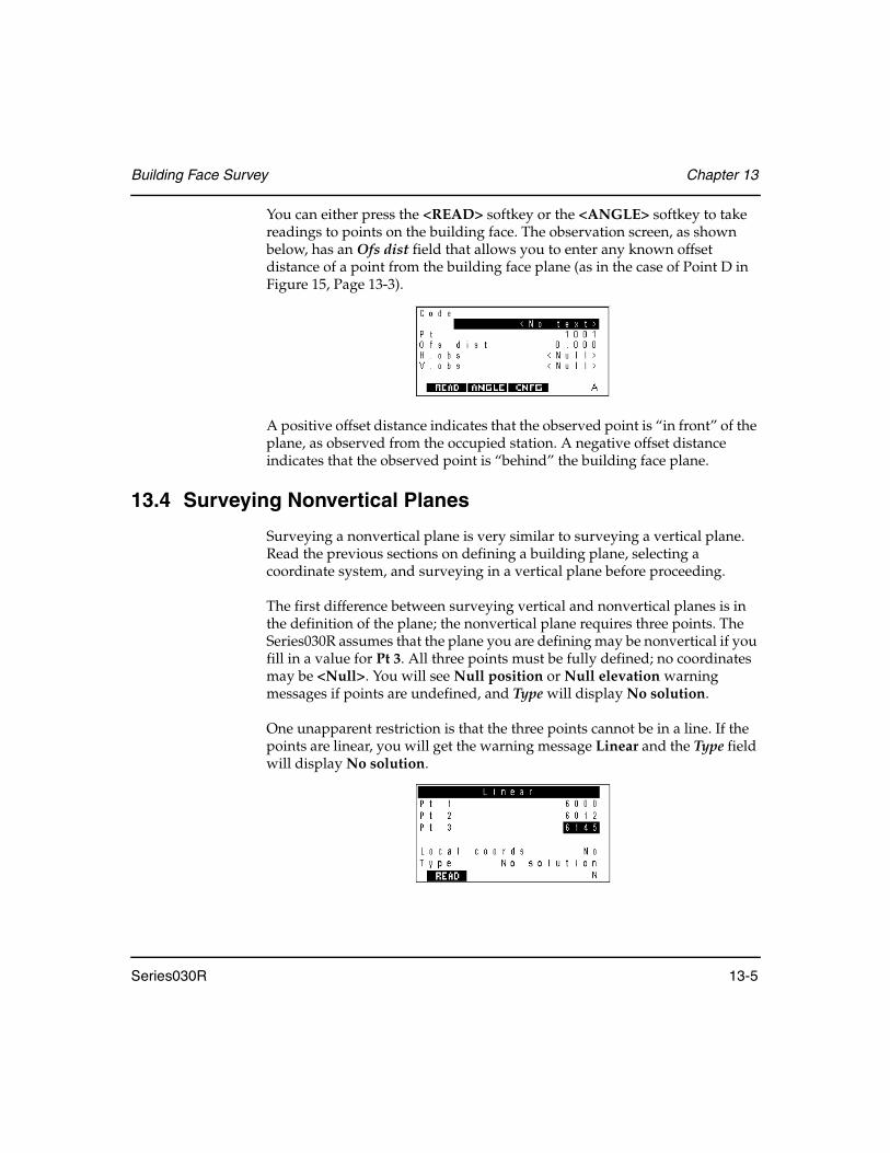
Building Face Survey Chapter 13
Series030R 13-5
You can either press the <READ> softkey or the <ANGLE> softkey to take readings to points on the building face. The observation screen, as shown below, has an Ofs dist field that allows you to enter any known offset distance of a point from the building face plane (as in the case of Point D in Figure 15, Page 13-3).
A positive offset distance indicates that the observed point is “in front” of the plane, as observed from the occupied station. A negative offset distance indicates that the observed point is “behind” the building face plane.
13.4 Surveying Nonvertical Planes
Surveying a nonvertical plane is very similar to surveying a vertical plane. Read the previous sections on defining a building plane, selecting a coordinate system, and surveying in a vertical plane before proceeding.
The first difference between surveying vertical and nonvertical planes is in the definition of the plane; the nonvertical plane requires three points. The Series030R assumes that the plane you are defining may be nonvertical if you fill in a value for Pt 3. All three points must be fully defined; no coordinates may be <Null>. You will see Null position or Null elevation warning messages if points are undefined, and Type will display No solution.
One unapparent restriction is that the three points cannot be in a line. If the points are linear, you will get the warning message Linear and the Type field will display No solution.
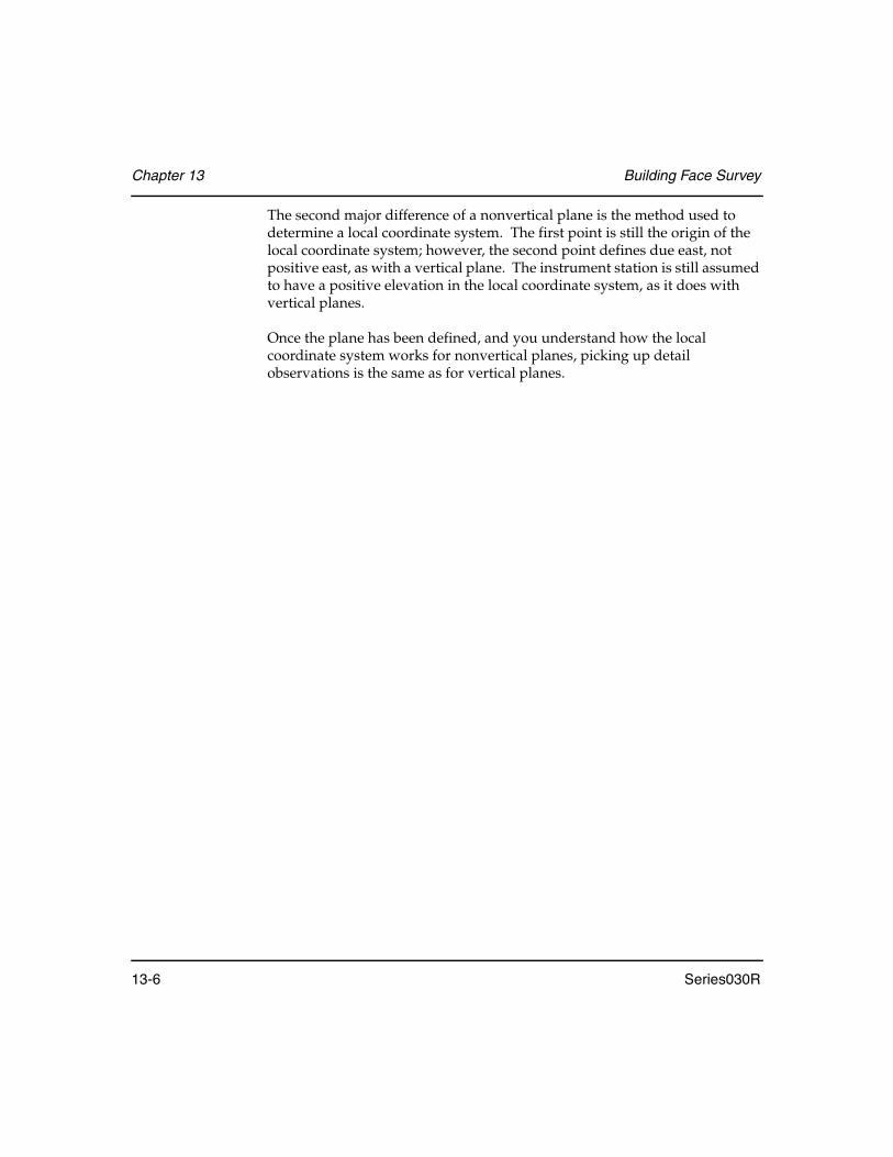
Chapter 13 Building Face Survey
13-6 Series030R
The second major difference of a nonvertical plane is the method used to determine a local coordinate system. The first point is still the origin of the local coordinate system; however, the second point defines due east, not positive east, as with a vertical plane. The instrument station is still assumed to have a positive elevation in the local coordinate system, as it does with vertical planes.
Once the plane has been defined, and you understand how the local coordinate system works for nonvertical planes, picking up detail observations is the same as for vertical planes.

Series030R 14-1
Chapter 14 Resection/Positioning
Based on the SDR software version installed, Series030R provides one of the two methods described below for calculating the coordinates of an unknown or free station.
Resection ................... Uses least squares adjustment techniques to determine the coordinates of an unknown point.
Positioning ................ Uses a balanced last absolute value estimation and mathematical techniques to determine the coordinates of an unknown point and any observational errors.
Observations are made using the Set Collection program in the Survey menu; sets may be collected prior to using the resection or positioning program.
14.1 Using Resection
The Resection program calculates the coordinates of an unknown station by observing a number of known positions from the unknown point. The Series030R performs a least squares reduction so that all data is used; redundant data generates better statistical results.
In this chapter
• Steps for completing a resection
• Series030R's calculation of a resection
• Steps for eccentric station setup as a normal resection
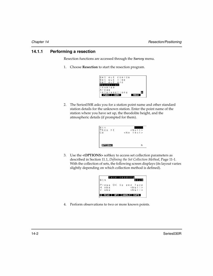
Chapter 14 Resection/Positioning
14-2 Series030R
14.1.1 Performing a resection
Resection functions are accessed through the Survey menu.
1. Choose Resection to start the resection program.
2. The Series030R asks you for a station point name and other standard station details for the unknown station. Enter the point name of the station where you have set up, the theodolite height, and the atmospheric details (if prompted for them).
3. Use the <OPTIONS> softkey to access set collection parameters as described in Section 11.1, Defining the Set Collection Method, Page 11-1. With the collection of sets, the following screen displays (its layout varies slightly depending on which collection method is defined).
4. Perform observations to two or more known points.

Resection/Positioning Chapter 14
Series030R 14-3
5. After you are finished with observations, choose from three options, which are described in the following sections.
14.1.1.1 Calculate resection
When you select this option, the Series030R calculates the coordinates of the station point. If redundant data exists, a least squares calculation is performed. The screen displays Processing data and the number of the current iteration.
When calculations are complete, the Series030R displays a station record containing the calculated coordinates:
Use the <EDIT> softkey if you want to change the code. Otherwise, press <Enter> to store the record. If you press <Enter>, the Series030R stores a series of notes that show the differences between the expected and actual observation values for each point. For example, if the Series030R calculates station coordinates of 100, 300, the Series030R calculates the inverse from the station to each observed point. The notes show the difference between the calculated inverse and the actual observations:
To cancel this process, press <ESC>.

Chapter 14 Resection/Positioning
14-4 Series030R
14.1.1.2 Collect more sets
If you are not satisfied with the resection coordinates produced, you can collect more sets to recalculate coordinates.
14.1.1.3 Review existing sets
Before you select Calculate resection, you can use this option to view the data collected. If you find a set with errors, mark it “BAD” so it will not be used in calculations. An asterisk denotes a bad set as shown below:
(For information on reviewing sets and marking a set as BAD, see Section 11.3.7.2, GOOD and BAD Sets, Page 11-23.)
You can repeatedly review the observations and perform the resection calculation to see the effect of excluding a set.
14.1.2 Understanding resection calculations
Resection requires a minimum of either of the following:
• Two observations with horizontal and vertical angles, including at least one slope distance
• Three observations with horizontal angles
The Series030R calculates a preliminary X-Y position from the minimum required data. It uses this result as the basis of a least squares reduction involving all the data. This iterative process terminates when the change in both the X and Y coordinates is less than 0.001 meters from one iteration to the next. The iterative process also terminates if convergence does not occur within nine iterations because the reduction is not stable.
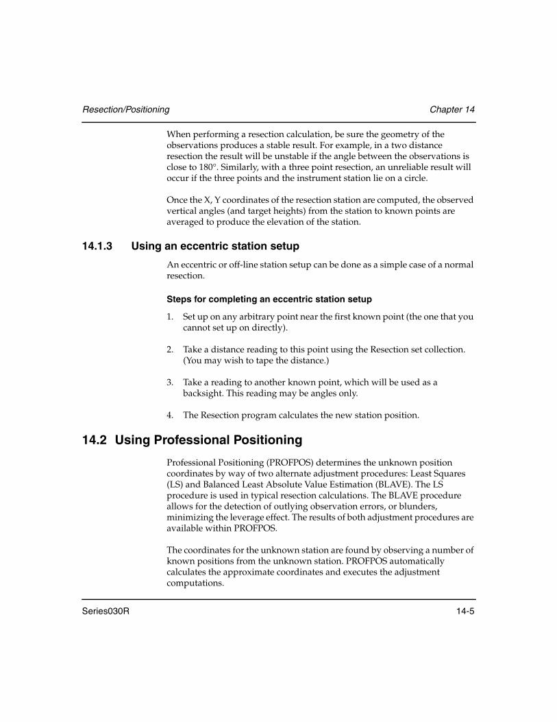
Resection/Positioning Chapter 14
Series030R 14-5
When performing a resection calculation, be sure the geometry of the observations produces a stable result. For example, in a two distance resection the result will be unstable if the angle between the observations is close to 180°. Similarly, with a three point resection, an unreliable result will occur if the three points and the instrument station lie on a circle.
Once the X, Y coordinates of the resection station are computed, the observed vertical angles (and target heights) from the station to known points are averaged to produce the elevation of the station.
14.1.3 Using an eccentric station setup
An eccentric or off-line station setup can be done as a simple case of a normal resection.
Steps for completing an eccentric station setup
1. Set up on any arbitrary point near the first known point (the one that you cannot set up on directly).
2. Take a distance reading to this point using the Resection set collection. (You may wish to tape the distance.)
3. Take a reading to another known point, which will be used as a backsight. This reading may be angles only.
4. The Resection program calculates the new station position.
14.2 Using Professional Positioning
Professional Positioning (PROFPOS) determines the unknown position coordinates by way of two alternate adjustment procedures: Least Squares (LS) and Balanced Least Absolute Value Estimation (BLAVE). The LS procedure is used in typical resection calculations. The BLAVE procedure allows for the detection of outlying observation errors, or blunders, minimizing the leverage effect. The results of both adjustment procedures are available within PROFPOS.
The coordinates for the unknown station are found by observing a number of known positions from the unknown station. PROFPOS automatically calculates the approximate coordinates and executes the adjustment computations.
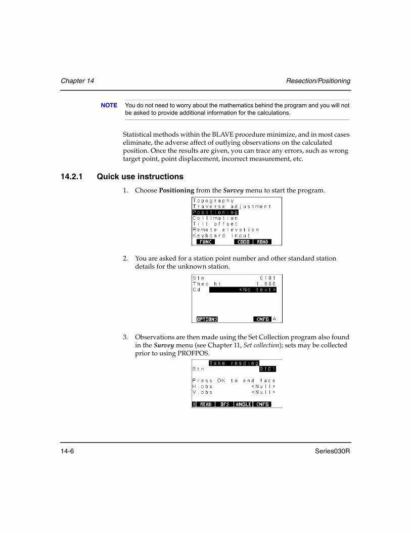
Chapter 14 Resection/Positioning
14-6 Series030R
NOTE You do not need to worry about the mathematics behind the program and you will not be asked to provide additional information for the calculations.
Statistical methods within the BLAVE procedure minimize, and in most cases eliminate, the adverse affect of outlying observations on the calculated position. Once the results are given, you can trace any errors, such as wrong target point, point displacement, incorrect measurement, etc.
14.2.1 Quick use instructions
1. Choose Positioning from the Survey menu to start the program.
2. You are asked for a station point number and other standard station details for the unknown station.
3. Observations are then made using the Set Collection program also found in the Survey menu (see Chapter 11, Set collection); sets may be collected prior to using PROFPOS.

Resection/Positioning Chapter 14
Series030R 14-7
4. After you are finished with observations, PROFPOS displays:
5. The Calculate Position option will provide the results for the selected method as shown in the screens below:
6. Either screen can be alternately displayed by changing the configured procedure via the <CFNG> softkey. Pressing <Enter> stores the configured position; <ESC> discards it.
14.2.2 Detailed use instructions
1. Choose Survey | Positioning to start the program.
2. You are asked for a station point number and other standard station details for the unknown station.
or

Chapter 14 Resection/Positioning
14-8 Series030R
3. Enter the point name of the station you have set up on, the theodolite height, and atmospheric details if you are prompted for them. The <OPTIONS> softkey can be used to change the parameters of set collection.
4. The <CNFG> softkey allows you to change which adjustment procedure’s calculated position is displayed on the initial results screen. The options are BLAVE and Least Squares.
5. Press <Enter> to continue. Depending on your set collection parameters, PROFPOS returns a screen similar to the following:
6. Standard set collection is used to take observations to known points (see Chapter 11, Set Collection).

Resection/Positioning Chapter 14
Series030R 14-9
7. Complete the observations and end set collection. Observations on Face 1 and Face 2 of the instrument are averaged as are multiple sets of observations. Observational errors can be minimized by distribution through the average.
However the BLAVE procedure statistically detects these errors, a more important property is real redundancy within a set of observations. By introducing more observations to unique points than necessary, thus redundancy, determination of the unknown position is achieved with more accuracy and better error detection. Redundant data generates better statistical results.
8. Once you complete the observations, PROFPOS shows you the three options displayed below:
Select one of the options. Descriptions of the options are explained in the following sections.
14.2.2.1 Calculate position
When you select this option, PROFPOS calculates the coordinates of the station point. The screen displays “Processing data” as seen below.
Calculations are performed for both adjustment procedures. When warranted, applicable error and/or warning messages will be displayed at this time. A discussion of each error/warning message can be found in Section 14.2.4, Professional positioning error/warning messages, Page 14-17.
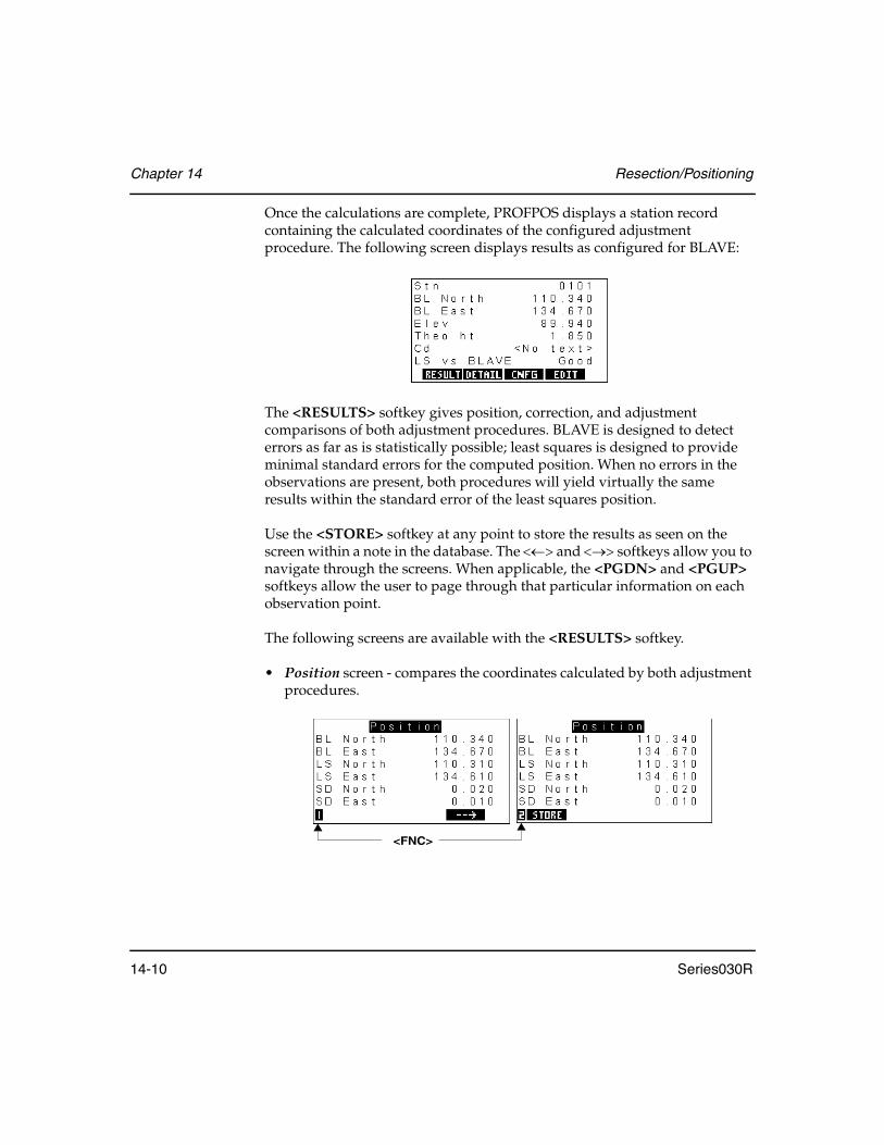
Chapter 14 Resection/Positioning
14-10 Series030R
Once the calculations are complete, PROFPOS displays a station record containing the calculated coordinates of the configured adjustment procedure. The following screen displays results as configured for BLAVE:
The <RESULTS> softkey gives position, correction, and adjustment comparisons of both adjustment procedures. BLAVE is designed to detect errors as far as is statistically possible; least squares is designed to provide minimal standard errors for the computed position. When no errors in the observations are present, both procedures will yield virtually the same results within the standard error of the least squares position.
Use the <STORE> softkey at any point to store the results as seen on the screen within a note in the database. The <←> and <→> softkeys allow you to navigate through the screens. When applicable, the <PGDN> and <PGUP> softkeys allow the user to page through that particular information on each observation point.
The following screens are available with the <RESULTS> softkey.
• Position screen - compares the coordinates calculated by both adjustment procedures.
<FNC>
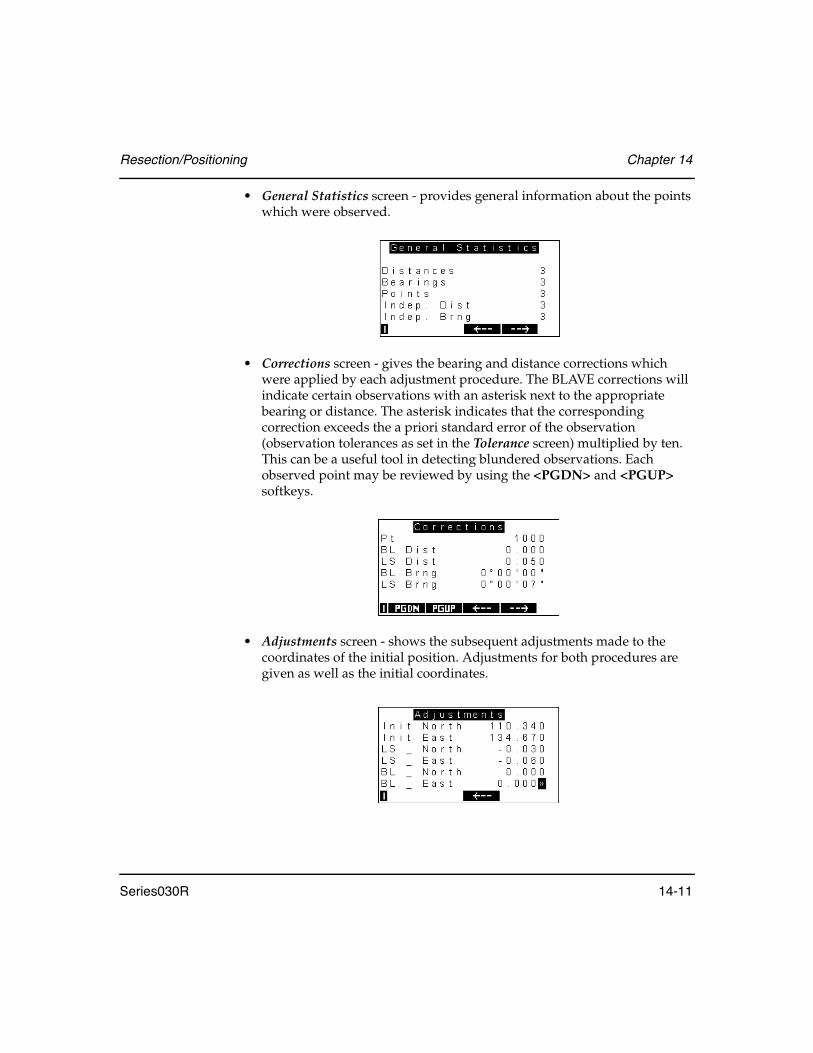
Resection/Positioning Chapter 14
Series030R 14-11
• General Statistics screen - provides general information about the points which were observed.
• Corrections screen - gives the bearing and distance corrections which were applied by each adjustment procedure. The BLAVE corrections will indicate certain observations with an asterisk next to the appropriate bearing or distance. The asterisk indicates that the corresponding correction exceeds the a priori standard error of the observation (observation tolerances as set in the Tolerance screen) multiplied by ten. This can be a useful tool in detecting blundered observations. Each observed point may be reviewed by using the <PGDN> and <PGUP> softkeys.
• Adjustments screen - shows the subsequent adjustments made to the coordinates of the initial position. Adjustments for both procedures are given as well as the initial coordinates.

Chapter 14 Resection/Positioning
14-12 Series030R
The <DETAILS> softkey shows advanced least squares statistical data. Three screens are displayed:
• Numerical Accuracy• Advanced LS Stats• Advanced LS Results
You may use the softkeys as described above.
• The Ansermet data, as seen in the Numerical Accuracy screen above, reveals information about the observations. An Ansermet of zero indicates that there is no real redundancy in the adjustment. A separate warning screen is displayed prior to the display of the calculated position coordinates to warn the user of this situation.
In the case of no redundancy (Ansermet = 0.0), error detection is not possible and all corrections become zero.
A typical Ansermet will be an integer value greater than zero. If an Ansermet is equal to 1, corrections are given but error detection is not theoretically possible. The same redundancy warning is displayed. If the Ansermet is not an integer value, it is an indication that computing problems were encountered in the adjustment.
The next two screens, the Advanced LS Stats screen and the Advanced LS Results screen, are intended to give an understanding of the least squares results. Since the BLAVE procedure statistically detects errors and distributes the partial redundancies (see Section 14.2.5, Understanding professional positioning results, Page 14-18), these screens are intended as additional tools to interpret results.
<FNC>

Resection/Positioning Chapter 14
Series030R 14-13
• The Advanced LS Stats screen gives the reduced bearing and distance as well as the standard error bearing and distance for the observed points. Each point can be shown by paging up and down.
The Advanced LS Stats screen gives the partial redundancies, RED Brng and RED Dist, which range in value from 0.0 to 1.0. A large value (close to 1.0) has a minimal impact on the LS adjustment while a small value has a greater affect. Summing of these values leads to the degree of freedom. Equal numerical values for RED indicates equal distribution of the partial redundancies and therefore an ideal LS target point constellation. The Std Err Brng and Dist are a test for errors within a single point adjustment derived from LS statistics.
• An error ellipse, as shown in Advanced LS Results, can be calculated to indicate the major and minor axis (A and B) of the ellipse related to the target point coordinate system. The azimuth T indicates the bearing of the major axis. The information is useful for location accuracy properties. Ideally, the error ellipse becomes a circle, when the major and minor axis are equal (A = B).

Chapter 14 Resection/Positioning
14-14 Series030R
While in RESULTS or DETAILS, pressing the <ESC> or <Enter> will return you to the station record screen.
If you press <Enter>, PROFPOS stores the station record as well as a note stating which adjustment method was used to determine the coordinates. If you press <ESC>, a confirmation prompt verifies that the station record will be discarded.
The <CNFG> softkey allows you to change which adjustment method’s results will be displayed in the station record screen.
To change the configured adjustment procedure, use the left and right arrow buttons to toggle between BLAVE and Least Squares. The following screen displays results as configured for least squares:
The coordinate qualifier of LS is used for least squares and BL for BLAVE. The Stn Pos field is used for least squares as seen above. The least squares point standard deviation, multiplied by two, is compared to a user-supplied tolerance in the Functions menu under Tolerances.

Resection/Positioning Chapter 14
Series030R 14-15
If it exceeds it, the Stn pos is determined as “Bad.” This means you may need to further continue checking your results.
The BLAVE results uses LS vs. BLAVE as seen on previous screens. The user-supplied tolerance is applied to the horizontal distance between the determined station position of both adjustment procedures (multiplied by two). If it is exceeded, LS vs. BLAVE is marked “Bad”, indicating the results of the two procedures deviate from each other.
Use the <EDIT> softkey if you want to change the station’s feature code.
14.2.2.2 Collect more sets
If you are not satisfied with the positioning coordinates produced, you can collect more sets with which to recalculate coordinates.
14.2.2.3 Review existing sets
Before you select Calculate position, you can use this option to view the data collected. (For information on reviewing sets, see Chapter 11, Set collection) If you find a set with errors, mark it “BAD” so it will not be used in calculations. An asterisk denotes a bad set as shown below:
You can repeatedly review the observations and perform the position calculation to see the effect of excluding a set.
14.2.3 Professional positioning input
Two separate adjustment procedures are available within professional positioning: Least Squares (LS) and Balanced Least Absolute Value Estimation (BLAVE). The LS and BLAVE procedures differ in their initial estimation technique. The BLAVE estimation technique allows for detection of errors.
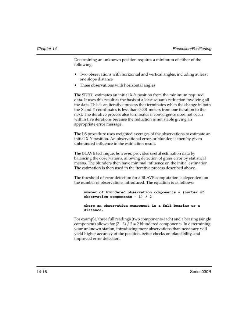
Chapter 14 Resection/Positioning
14-16 Series030R
Determining an unknown position requires a minimum of either of the following:
• Two observations with horizontal and vertical angles, including at least one slope distance
• Three observations with horizontal angles
The SDR31 estimates an initial X-Y position from the minimum required data. It uses this result as the basis of a least squares reduction involving all the data. This is an iterative process that terminates when the change in both the X and Y coordinates is less than 0.001 meters from one iteration to the next. The iterative process also terminates if convergence does not occur within five iterations because the reduction is not stable giving an appropriate error message.
The LS procedure uses weighted averages of the observations to estimate an initial X-Y position. An observational error, or blunder, is thereby given unbounded influence to the estimation result.
The BLAVE technique, however, provides useful estimation data by balancing the observations, allowing detection of gross error by statistical means. The blunders then have minimal influence on the initial estimation. The estimation is then used in the iterative process described above.
The threshold of error detection for a BLAVE computation is dependent on the number of observations introduced. The equation is as follows:
number of blundered observation components = (number of observation components - 3) / 2
where an observation component is a full bearing or a distance.
For example, three full readings (two components each) and a bearing (single component) allows for (7 - 3) / 2 = 2 blundered components. In determining your unknown station, introducing more observations than necessary will yield higher accuracy of the position, better checks on plausibility, and improved error detection.
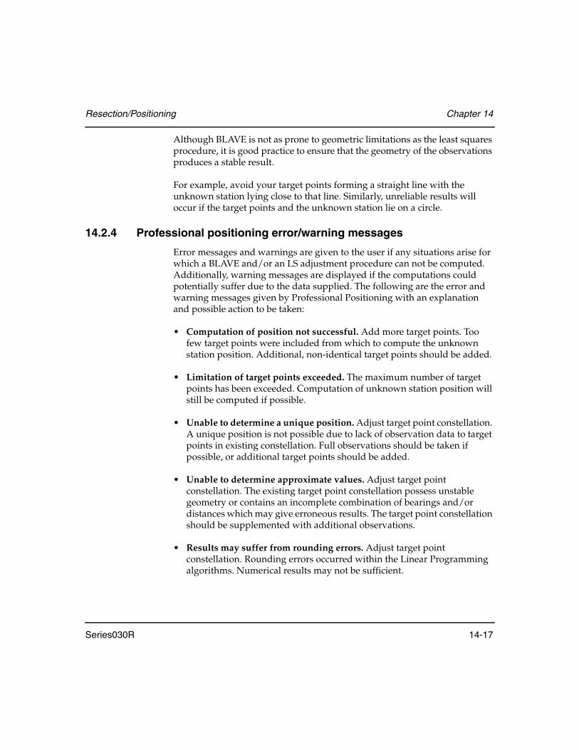
Resection/Positioning Chapter 14
Series030R 14-17
Although BLAVE is not as prone to geometric limitations as the least squares procedure, it is good practice to ensure that the geometry of the observations produces a stable result.
For example, avoid your target points forming a straight line with the unknown station lying close to that line. Similarly, unreliable results will occur if the target points and the unknown station lie on a circle.
14.2.4 Professional positioning error/warning messages
Error messages and warnings are given to the user if any situations arise for which a BLAVE and/or an LS adjustment procedure can not be computed. Additionally, warning messages are displayed if the computations could potentially suffer due to the data supplied. The following are the error and warning messages given by Professional Positioning with an explanation and possible action to be taken:
• Computation of position not successful. Add more target points. Too few target points were included from which to compute the unknown station position. Additional, non-identical target points should be added.
• Limitation of target points exceeded. The maximum number of target points has been exceeded. Computation of unknown station position will still be computed if possible.
• Unable to determine a unique position. Adjust target point constellation. A unique position is not possible due to lack of observation data to target points in existing constellation. Full observations should be taken if possible, or additional target points should be added.
• Unable to determine approximate values. Adjust target point constellation. The existing target point constellation possess unstable geometry or contains an incomplete combination of bearings and/or distances which may give erroneous results. The target point constellation should be supplemented with additional observations.
• Results may suffer from rounding errors. Adjust target point constellation. Rounding errors occurred within the Linear Programming algorithms. Numerical results may not be sufficient.
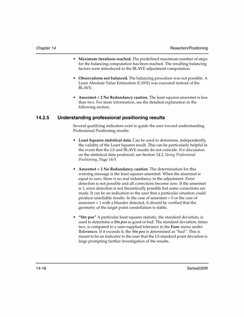
Chapter 14 Resection/Positioning
14-18 Series030R
• Maximum iterations reached. The predefined maximum number of steps for the balancing computation has been reached. The resulting balancing factors were introduced to the BLAVE adjustment computation.
• Observations not balanced. The balancing procedure was not possible. A Least Absolute Value Estimation (LAVE) was executed instead of the BLAVE.
• Ansermet < 2 No Redundancy caution. The least squares ansermet is less than two. For more information, see the detailed explanation in the following section.
14.2.5 Understanding professional positioning results
Several qualifying indicators exist to guide the user toward understanding Professional Positioning results:
• Least Squares statistical data. Can be used to determine, independently, the validity of the Least Squares result. This can be particularly helpful in the event that the LS and BLAVE results do not coincide. For discussion on the statistical data produced, see Section 14.2, Using Professional Positioning, Page 14-5.
• Ansermet < 2 No Redundancy caution. The determination for this warning message is the least squares ansermet. When the ansermet is equal to zero, there is no real redundancy in the adjustment. Error detection is not possible and all corrections become zero. If the ansermet is 1, error detection is not theoretically possible but some corrections are made. It can be an indication to the user that a particular situation could produce unreliable results. In the case of ansermet = 0 or the case of ansermet = 1 with a blunder detected, it should be verified that the geometry of the target point constellation is stable.
• “Stn pos” A particular least squares statistic, the standard deviation, is used to determine a Stn pos as good or bad. The standard deviation, times two, is compared to a user-supplied tolerance in the Func menu under Tolerances. If it exceeds it, the Stn pos is determined as “bad”. This is meant to be an indicator to the user that the LS standard point deviation is large prompting further investigation of the results.

Resection/Positioning Chapter 14
Series030R 14-19
• “LS vs. BLAVE” That same tolerance is applied to the horizontal distance between the determined unknown station position of both adjustment procedures (times two). It informs the user when the results of the two procedures deviate from each other. This would be expected in the presence of blunders which typically, and incorrectly, alter a Least Squares position.
• Blunder detection. Because blunders have an adverse affect on Least Squares adjustments and are helpful in explaining the status of other indicators, it is important for the user to be made aware of their presence. A target point observation, bearing or distance, is marked as a blunder if the corresponding correction exceeds the a priori standard error of the observation multiplied by ten. The a priori standard error of the observation are the observation tolerances set in the Tolerance screen in the Func menu.
14.2.6 Professional positioning calculations
The method of Least Squares minimizes the sum of the squared residuals. The Least Absolute Value Estimation (LAVE) minimizes the sum of the absolute residuals. To demonstrate, consider the data set below:
The fifth observation is an obvious outlying observation. The arithmetic mean is determined by summing all observations and dividing by the total number of observations (42/5 = 8.4). The median is found by ordering the observations by their size and taking the middle one. The following table shows the residuals of the data set to the arithmetic mean and to the median:
No. 1 2 3 4 5
Size 3.0 3.0 3.0 3.0 30.0
Arithmetic Mean 8.4
Median 3.0
No. 1 2 3 4 5
Arithmetic Mean(Least Squares)
5.4 5.4 5.4 5.4 21.6
Median (LAVE) 0.0 0.0 0.0 0.0 -27.0

Chapter 14 Resection/Positioning
14-20 Series030R
As seen in the table above LAVE, by using the median, is able to determine the outlying observation by the size of the residual. However, it is not effective in cases of more than one unknown parameter.
In contrast to LAVE, the Least Squares adjustment procedure is subject to “smearing effects” due to its utilization of the arithmetic mean as shown above. An outlying target point observation, or blunder, may therefore totally spoil an ordinary least squares adjustment. The outlying observations occur at a distance from the bulk of observations, from its center of gravity, thereby holding the character of “leverage”. The data set shown below illustrates this point.
It can be seen that the bias of these leverage points would adversely affect the formulation of the initial X,Y position, or estimation. A more comprehensive adjustment procedure must determine this estimation by considering all observations without any preliminary selection, or bias. To achieve this result, robust statistical techniques have been developed which are minimally affected by these outlying observations, or blunders. These techniques have been incorporated into the Balanced Least Absolute Value Estimation (BLAVE) adjustment procedure which, in turn, is the essence of Professional Positioning. To better understand the BLAVE technique, further explanation of least squares is needed.
An ordinary least squares procedure begins with the linear model:
A x = l + v with D(l) = σ2 P-1
Let n = number of observations and u = number of unknowns. A = (n,u) matrix of coefficients, x = (u,1) vector of unknowns, l = (n,1) vector of observations, and v = (n,1) vector of corrections, or residuals.
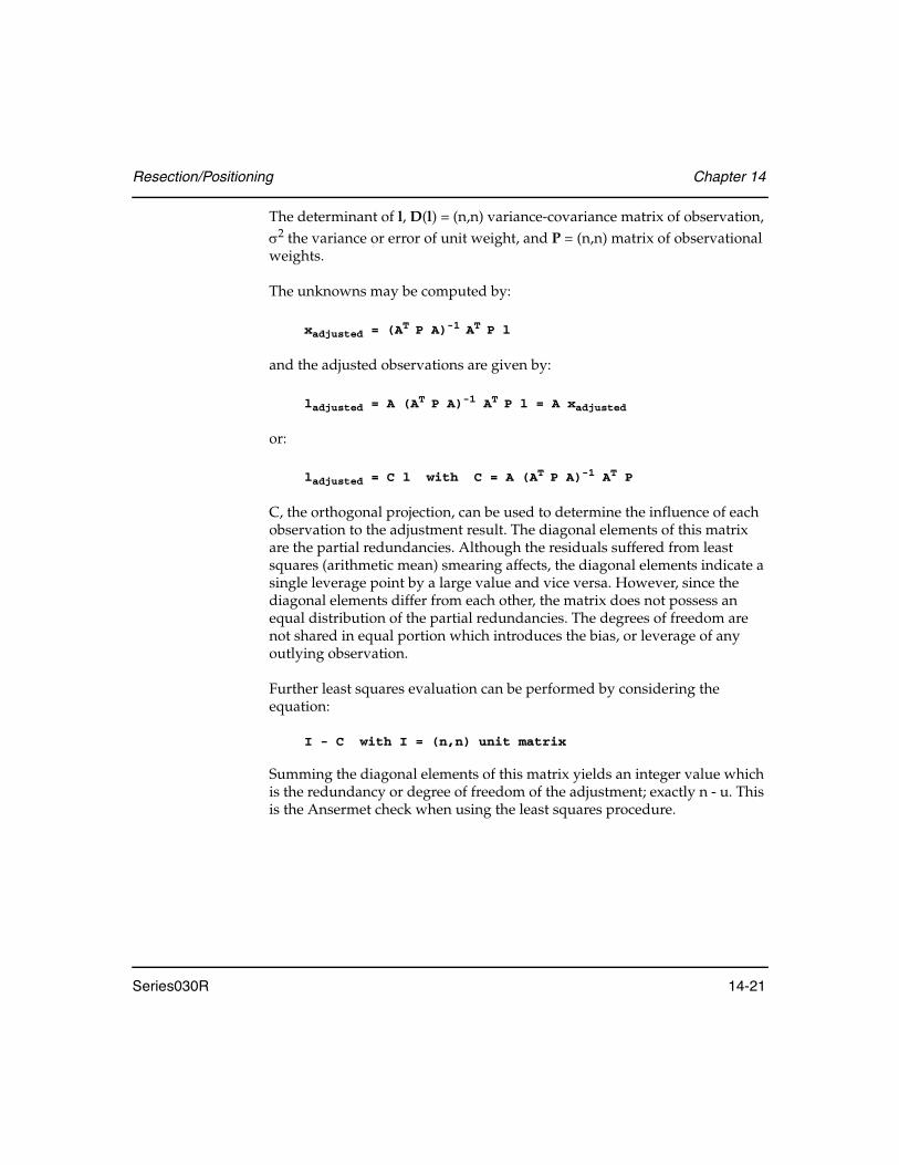
Resection/Positioning Chapter 14
Series030R 14-21
The determinant of l, D(l) = (n,n) variance-covariance matrix of observation, σ2 the variance or error of unit weight, and P = (n,n) matrix of observational weights.
The unknowns may be computed by:
xadjusted = (AT P A)-1 AT P l
and the adjusted observations are given by:
ladjusted = A (AT P A)-1 AT P l = A xadjusted
or:
ladjusted = C l with C = A (AT P A)-1 AT P
C, the orthogonal projection, can be used to determine the influence of each observation to the adjustment result. The diagonal elements of this matrix are the partial redundancies. Although the residuals suffered from least squares (arithmetic mean) smearing affects, the diagonal elements indicate a single leverage point by a large value and vice versa. However, since the diagonal elements differ from each other, the matrix does not possess an equal distribution of the partial redundancies. The degrees of freedom are not shared in equal portion which introduces the bias, or leverage of any outlying observation.
Further least squares evaluation can be performed by considering the equation:
I - C with I = (n,n) unit matrix
Summing the diagonal elements of this matrix yields an integer value which is the redundancy or degree of freedom of the adjustment; exactly n - u. This is the Ansermet check when using the least squares procedure.

Chapter 14 Resection/Positioning
14-22 Series030R
The BLAVE procedure differs in two fundamental areas. First, the initial linear model (A x = l + v) is developed by utilizing LAVE (median) to determine v, the vector of residuals. Second, a matrix PG that enables the same numerical values to the diagonal elements of the orthogonal projection is determined by
(A (AT PG A)-1 AT PG) = Constant
The matrix PG, which now represents the matrix of balanced observation weights, is introduced to the LAVE creating a BLAVE (Balanced Least Absolute Value Estimation).
The aforementioned differences between the least squares and BLAVE procedures minimize the smearing effect by using the principle of the median and minimize the leverage effects of outlying observations by equally distributing the partial redundancies respectfully. These are the characteristics which give BLAVE, and subsequently Professional Positioning, its robust error detection capabilities.
Once the X, Y coordinates of the unknown station are computed, the observed vertical angles (and target heights) to the known points are averaged to produce the elevation of the station.
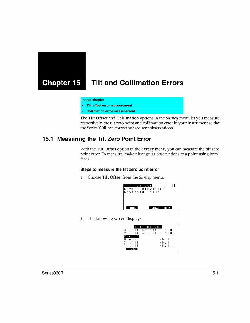
Series030R 15-1
Chapter 15 Tilt and Collimation Errors
The Tilt Offset and Collimation options in the Survey menu let you measure, respectively, the tilt zero point and collimation error in your instrument so that the Series030R can correct subsequent observations.
15.1 Measuring the Tilt Zero Point Error
With the Tilt Offset option in the Survey menu, you can measure the tilt zero point error. To measure, make tilt angular observations to a point using both faces.
Steps to measure the tilt zero point error
1. Choose Tilt Offset from the Survey menu.
2. The following screen displays:
In this chapter
• Tilt offset error measurement
• Collimation error measurement

Chapter 15 Tilt and Collimation Errors
15-2 Series030R
3. Press the <READ> softkey to observe the point using Face 1, and the following screen displays:
4. Press the <READ> softkey again to observe the point using Face 2, and the following screen appears, which displays the new tilt offset data:
5. Press <Enter> if you want to accept the results and store a tilt offset value to the Series030R. Pressing <ESC> results in a confirmation prompt to discard data:
Once a tilt offset value is stored to the Series030R, corrections are applied to all subsequent observations until a new tilt offset value is stored
15.2 Measuring Collimation Error
The Collimation option in the Survey menu allows you to measure the collimation error in your instrument so that the Series030R can correct subsequent single face observations. The errors are measured by making angular observations using both faces of the instrument to one or many points. The minimum required data is a Face 1 (F1) observation and a Face 2 (F2) observation to a single point.

Tilt and Collimation Errors Chapter 15
Series030R 15-3
Steps for completing collimation error measurement
1. Choose Collimation from the Survey menu.
2. Begin with the standard station and backsight setup as described in Chapter 9, Station Setup and Backsight.
3. The Series030R prompts you to sight the first point using Face 1 of your instrument:
4. Press the <READ> softkey for regular observations or the <ANGLE> softkey for angles-only observations to the point using Face 1.
The <CNFG> softkey accesses the Configure reading screen. For more information, see Section 4.2.4, Configure reading, Page 4-6.
5. The Series030R prompts you to sight the same point using Face 2:
6. Press the <READ> softkey or the <ANGLE> softkey to observe the point using Face 2. This completes the minimum set of readings necessary to calculate collimation error.
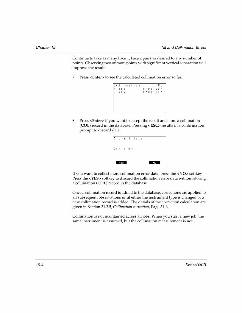
Chapter 15 Tilt and Collimation Errors
15-4 Series030R
Continue to take as many Face 1, Face 2 pairs as desired to any number of points. Observing two or more points with significant vertical separation will improve the result.
7. Press <Enter> to see the calculated collimation error so far.
8. Press <Enter> if you want to accept the result and store a collimation (COL) record in the database. Pressing <ESC> results in a confirmation prompt to discard data.
If you want to collect more collimation error data, press the <NO> softkey. Press the <YES> softkey to discard the collimation error data without storing a collimation (COL) record in the database.
Once a collimation record is added to the database, corrections are applied to all subsequent observations until either the instrument type is changed or a new collimation record is added. The details of the correction calculation are given in Section 31.2.5, Collimation correction, Page 31-6.
Collimation is not maintained across all jobs. When you start a new job, the same instrument is assumed, but the collimation measurement is not.

Series030R 16-1
Chapter 16 Remote Elevation
Use the Remote Elevation program to coordinate points when you are unable to place a prism at the required point, but can place the prism either directly above or below the point. You observe (with a prism) a base point directly underneath or above the target point and then observe a vertical angle to the target point. The Series030R calculates the intersection of the extended vertical angle with a vertical line from the base point.
Steps to take a remote elevation reading
1. Select Remote elevation from the Survey menu.
2. Begin with the standard station and backsight setup as described in Chapter 9, Station Setup and Backsight.
3. Then the Series030R displays the following screen.
In this chapter
• Remote Elevation program

Chapter 16 Remote Elevation
16-2 Series030R
4. Direct the rodman to place the prism rod directly under the desired point. Point the survey instrument to the prism and press the <READ> softkey to observe the base point. The Series030R displays a screen similar to the following:
5. Press <Enter> to accept the base point observation. The Series030R will display the following screen.
6. As the scope moves up or down, the elevation value changes. Once sighted on the point, press the <STORE> softkey to record the values.
NOTE Height is the difference in height from the base point of the prism point to the observed target point.
7. You have three options.
• Press the <READ> softkey again to observe the point• Press the <STORE> softkey to accept the result and store it as a POS
(position) record.• Press <ESC> to exit.

Series030R 17-1
Chapter 17 Keyboard Input
You can enter data directly into the Series030R using the keyboard. Select Keyboard input from the Survey or COGO menus.
The Series030R displays four record types that are input from the keyboard.
In this chapter
• Entering coordinates
• Entering azimuths
• Entering azimuths with distances
• Entering observations
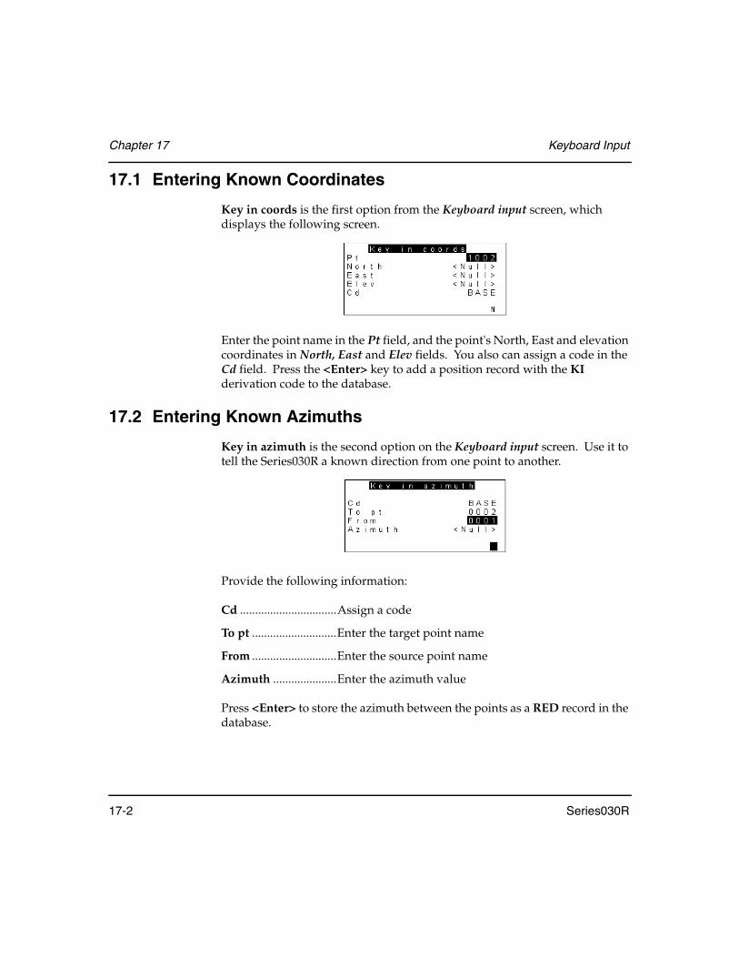
Chapter 17 Keyboard Input
17-2 Series030R
17.1 Entering Known Coordinates
Key in coords is the first option from the Keyboard input screen, which displays the following screen.
Enter the point name in the Pt field, and the point's North, East and elevation coordinates in North, East and Elev fields. You also can assign a code in the Cd field. Press the <Enter> key to add a position record with the KI derivation code to the database.
17.2 Entering Known Azimuths
Key in azimuth is the second option on the Keyboard input screen. Use it to tell the Series030R a known direction from one point to another.
Provide the following information:
Cd ................................Assign a code
To pt ............................Enter the target point name
From ............................Enter the source point name
Azimuth .....................Enter the azimuth value
Press <Enter> to store the azimuth between the points as a RED record in the database.
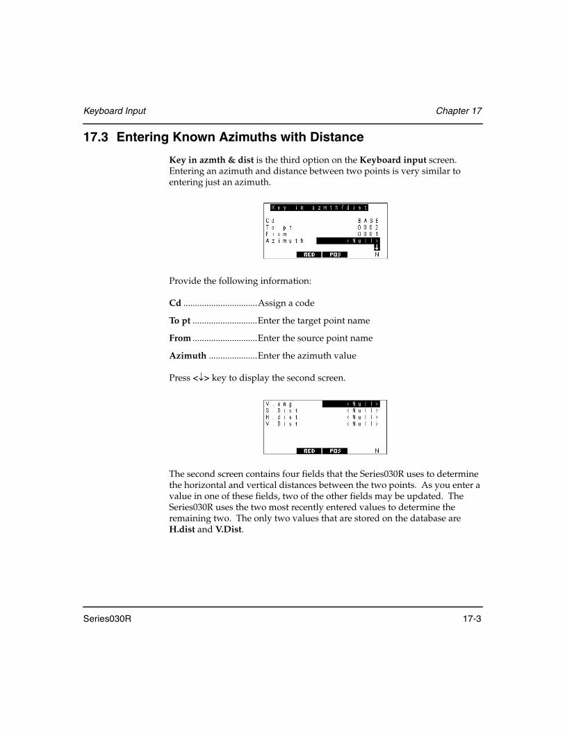
Keyboard Input Chapter 17
Series030R 17-3
17.3 Entering Known Azimuths with Distance
Key in azmth & dist is the third option on the Keyboard input screen. Entering an azimuth and distance between two points is very similar to entering just an azimuth.
Provide the following information:
Cd ................................Assign a code
To pt ............................Enter the target point name
From ............................Enter the source point name
Azimuth .....................Enter the azimuth value
Press <↓> key to display the second screen.
The second screen contains four fields that the Series030R uses to determine the horizontal and vertical distances between the two points. As you enter a value in one of these fields, two of the other fields may be updated. The Series030R uses the two most recently entered values to determine the remaining two. The only two values that are stored on the database are H.dist and V.Dist.

Chapter 17 Keyboard Input
17-4 Series030R
When you have the correct azimuth and distance values entered, use the following methods to store the information:
<RED> softkey or <Enter> .........The azimuth and distance data are stored in the database as a RED record in RED view
<POS> softkey..............................The RED record will be stored in POS view (thereby overriding any previous information about the point, see Chapter 7, Coordinate Search Logic for details on database searching)
17.4 Entering Known Observations
Use the Key in Obsvn option to enter a known vector from one point to another into the Series030R SDR database.
Keying in known observations requires a backsight point (BS pt). The following diagram illustrates the backsight point and its relation to other points.
Figure 16: Backsight point
N
To
HObs
AzBs
From
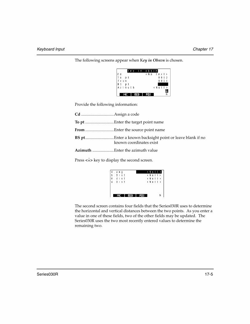
Keyboard Input Chapter 17
Series030R 17-5
The following screens appear when Key in Obsvn is chosen.
Provide the following information:
Cd ................................Assign a code
To pt ............................Enter the target point name
From ............................Enter the source point name
BS pt............................Enter a known backsight point or leave blank if no known coordinates exist
Azimuth .....................Enter the azimuth value
Press <↓> key to display the second screen.
The second screen contains four fields that the Series030R uses to determine the horizontal and vertical distances between the two points. As you enter a value in one of these fields, two of the other fields may be updated. The Series030R uses the two most recently entered values to determine the remaining two.

Chapter 17 Keyboard Input
17-6 Series030R
If you have a known backsight point, enter its point name in the BS pt field and press <Enter>. The Series030R displays the following screens.
The H. obs field has replaced the Azimuth field. Enter the horizontal angle in the H.obs field. Go to the second screen and enter values for V. ang, S. dist, H. dist, and V. dist as before.
When all distances and azimuths are correctly entered, use the following methods to store the information:
<MC> softkey or <Enter>........... Stores an MC record in MC view in the database
<RED> softkey ............................. Stores an MC record in RED view in the database
<POS> softkey.............................. Stores an MC record in POS view in the database

Series030R 18-1
Chapter 18 Set Out Design Coordinates
Use the Set out coords option in the COGO menu for positioning design coordinates in the field. It is necessary to set up your instrument on a known location. (The Resection/Positioning program allows you to conveniently set up on any suitable point.)
Begin with the standard station and backsight setup as described in Chapter 9, Station Setup and Backsight.
Once a station and backsigtht are set up, the Series030R checks for an existing list of points to set out for the job. If it finds a list, the Series030R displays it; if not the Series030R displays an empty list. From this screen you can enter, modify, insert, or delete point names in the set out list. You can also add all
In this chapter
• Adding points to the setout list
• Deleting points from the setout list
• Setting out a point
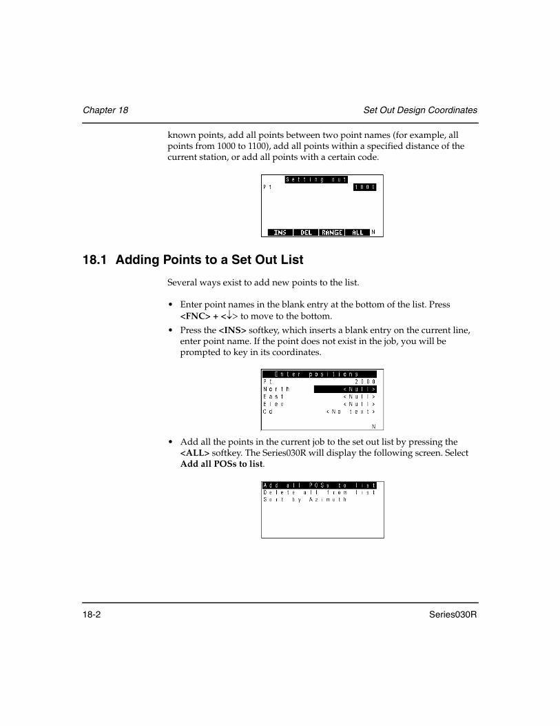
Chapter 18 Set Out Design Coordinates
18-2 Series030R
known points, add all points between two point names (for example, all points from 1000 to 1100), add all points within a specified distance of the current station, or add all points with a certain code.
18.1 Adding Points to a Set Out List
Several ways exist to add new points to the list.
• Enter point names in the blank entry at the bottom of the list. Press <FNC> + <↓> to move to the bottom.
• Press the <INS> softkey, which inserts a blank entry on the current line, enter point name. If the point does not exist in the job, you will be prompted to key in its coordinates.
• Add all the points in the current job to the set out list by pressing the <ALL> softkey. The Series030R will display the following screen. Select Add all POSs to list.
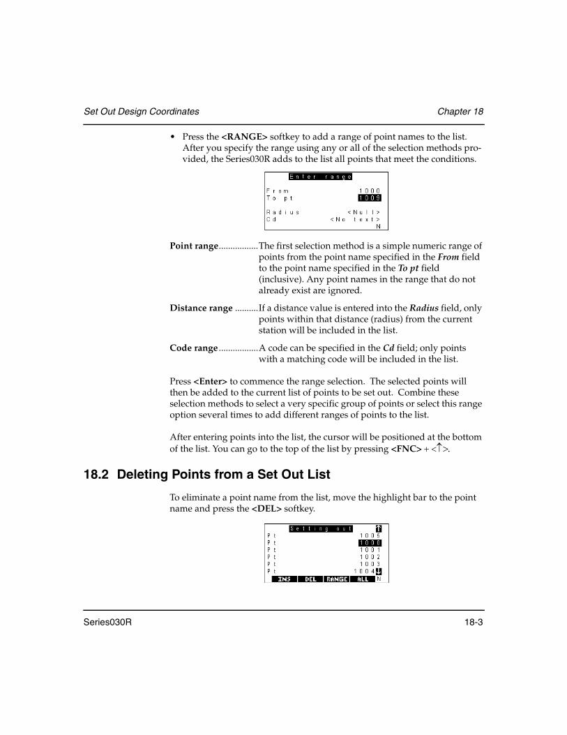
Set Out Design Coordinates Chapter 18
Series030R 18-3
• Press the <RANGE> softkey to add a range of point names to the list. After you specify the range using any or all of the selection methods pro-vided, the Series030R adds to the list all points that meet the conditions.
Point range.................The first selection method is a simple numeric range of points from the point name specified in the From field to the point name specified in the To pt field (inclusive). Any point names in the range that do not already exist are ignored.
Distance range ..........If a distance value is entered into the Radius field, only points within that distance (radius) from the current station will be included in the list.
Code range .................A code can be specified in the Cd field; only points with a matching code will be included in the list.
Press <Enter> to commence the range selection. The selected points will then be added to the current list of points to be set out. Combine these selection methods to select a very specific group of points or select this range option several times to add different ranges of points to the list.
After entering points into the list, the cursor will be positioned at the bottom of the list. You can go to the top of the list by pressing <FNC> + <↑>.
18.2 Deleting Points from a Set Out List
To eliminate a point name from the list, move the highlight bar to the point name and press the <DEL> softkey.

Chapter 18 Set Out Design Coordinates
18-4 Series030R
To remove all the point names from the list, press the <ALL> softkey. The Series030R will display the following screen. Select Delete all from list.
The Series030R will then display the screen for adding set out points.
18.3 Sorting a Set Out List by Azimuth
The Series030R can sort the set out list by azimuth as referenced from the current station to each point. Press the <ALL> softkey, and select Sort by Azimuth.
The Series030R will display a Working... message that will move up and down the screen as the Series030R sorts the list. A long list may take a couple of minutes to sort. When the sort is complete, the point entry list will be displayed. The point names will be in order of increasing azimuth, using the current station as the from point.

Set Out Design Coordinates Chapter 18
Series030R 18-5
18.4 Setting Out a Point
Guidelines for setting out a point are described below.
1. Choose a particular point from the list of points on the screen to set out by highlighting it and pressing <Enter>.
2. The Series030R shows you all the information required to set out the point: the necessary horizontal and vertical angles to observe, the desired slope distance to the point, the reduced horizontal and vertical distances, and the azimuth.
3. Align your instrument to the horizontal angle shown. The Series030R is put into countdown mode automatically to help you. Rotate the instrument until the countdown reaches zero, then direct the prism pole in line.
4. Sight on the prism and press the <READ> softkey on the Series030R. The following screen displays:
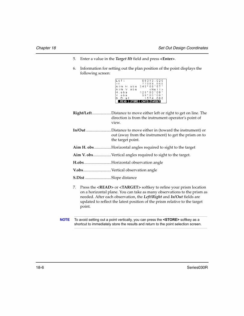
Chapter 18 Set Out Design Coordinates
18-6 Series030R
5. Enter a value in the Target Ht field and press <Enter>.
6. Information for setting out the plan position of the point displays the following screen:
Right/Left ...................Distance to move either left or right to get on line. The direction is from the instrument operator's point of view.
In/Out .........................Distance to move either in (toward the instrument) or out (away from the instrument) to get the prism on to the target point.
Aim H. obs .................Horizontal angles required to sight to the target
Aim V. obs..................Vertical angles required to sight to the target.
H.obs ...........................Horizontal observation angle
V.obs............................Vertical observation angle
S.Dist ..........................Slope distance
7. Press the <READ> or <TARGET> softkey to refine your prism location on a horizontal plane. You can take as many observations to the prism as needed. After each observation, the Left/Right and In/Out fields are updated to reflect the latest position of the prism relative to the target point.
NOTE To avoid setting out a point vertically, you can press the <STORE> softkey as a shortcut to immediately store the results and return to the point selection screen.

Set Out Design Coordinates Chapter 18
Series030R 18-7
8. Press <Enter> to continue to the setting out point vertically. The vertical setting out display is similar to this screen:
Cut/Fill........................Amount of cut or fill that the currently observed position represents relative to the design point. Remember that the currently observed point is the physical point at the bottom of the prism pole.
Cut o/s .........................Is normally zero. However, if the design point is underground, you may want to enter a Cut o/s value of 1.000, for example, to accurately stake an above ground mark. (To set out a fill offset, enter a negative value in the Cut o/s field.) The vertical angle in the V.obs field changes to reflect the new desired position. If you observe this vertical angle, the actual Cut value in the first field changes to 1.000.
Aim V.obs...................Vertical angle that should be observed to obtain the design height plus the cut offset.
H.obs ...........................Horizontal observation angle
V.obs............................Vertical observation angle
S.Dist ..........................Slope distance
The Series030R automatically starts a vertical countdown mode. When the countdown is zero, you will be sighting on the design elevation plus the value of the Cut offset.
9. Choose one of the following actions when the procedure is completed.
<ESC> .........................To return to setting out the plan position of the current point. This action might be necessary if the prism pole is inadvertently moved during the setting out of the elevation.

Chapter 18 Set Out Design Coordinates
18-8 Series030R
<STORE> ...................Press this softkey to store the current setout position.The Series030R then prepares to store the results, and will show you the default point name and code that it will use.
<Enter> .......................Press this key once a satisfactory elevation has been set out.
Table 12: Steps to Store the Setout Position
Step Description
1 Change the point name, the code or both. The default code includes a reference to the name of the point that was set out.
2 When the point name and code are acceptable, press <Enter>. A position record and note showing differences between design and actual position will be stored.
3 Press <ESC> to return to the setting out of points.
4 Once the position record is generated, the Series030R returns to the list of point names to be set out so that you can choose another point to set out. If the list is now empty, it will prompt you to add points to the list.

Series030R 19-1
Chapter 19 Set Out Line
This function can be used for setting out and checking alignment of curblines, construction boards, and grades of pipes.
A baseline or an offset from that baseline can be defined and its points set out in the field. Alternatively, a baseline can be established from which observations are described, allowing points to be set along the line of an offset.
Figure 17: Setting out a line
In this chapter
• Setting out points along a line, in either the horizontal or vertical plane
• Checking that points are on a defined alignment
Plan view
Profile view
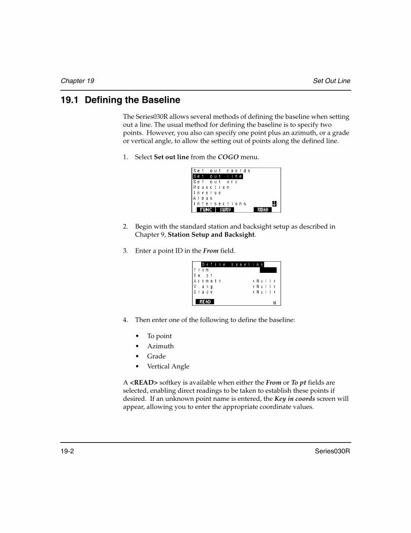
Chapter 19 Set Out Line
19-2 Series030R
19.1 Defining the Baseline
The Series030R allows several methods of defining the baseline when setting out a line. The usual method for defining the baseline is to specify two points. However, you also can specify one point plus an azimuth, or a grade or vertical angle, to allow the setting out of points along the defined line.
1. Select Set out line from the COGO menu.
2. Begin with the standard station and backsight setup as described in Chapter 9, Station Setup and Backsight.
3. Enter a point ID in the From field.
4. Then enter one of the following to define the baseline:
• To point• Azimuth• Grade• Vertical Angle
A <READ> softkey is available when either the From or To pt fields are selected, enabling direct readings to be taken to establish these points if desired. If an unknown point name is entered, the Key in coords screen will appear, allowing you to enter the appropriate coordinate values.

Set Out Line Chapter 19
Series030R 19-3
When the Grade field is selected, <HORIZ>, <1:>, and <%> softkeys are presented. The <HORIZ> softkey will set the Grade field to horizontal. The <1:> and <%> softkeys control the display and entry of grade values. If desired, up or down vertical grades can also be defined by entering the appropriate vertical angle values to suit the current instrument's V.obs setting. For example, if the current instrument setting is for Zenith vertical angles then entering a vertical angle of 0° or 0 gons will result in the Grade field displaying Up (Vert).
5. Press <Enter> to accept the entries.
19.2 Setting Out a Defined Line
Once the baseline is defined, you can set out the points which define the line.
1. The following Set out line screen displays (after the <Enter> key is pressed):
Offset ..........................Sets out points along a line parallel to the actual design line at the specified offset distance. This facility can be used to avoid the possibility of heavy machinery disturbing the stakes. A negative offset value indicates an offset to the left of the defined line.
Len incr.......................Specifies distance increments along the set out line at which you want to set out points. For example, if you wish to set out points every 20 feet (or meters) along the set out line, enter 20 into this field.
The < ← > and <→ > softkeys decrease and increase the current distance in the Line len field, for the point to be set out, by the value in the Len incr field.
Segments ....................Is displayed only if both the From and To points were specified for the baseline.
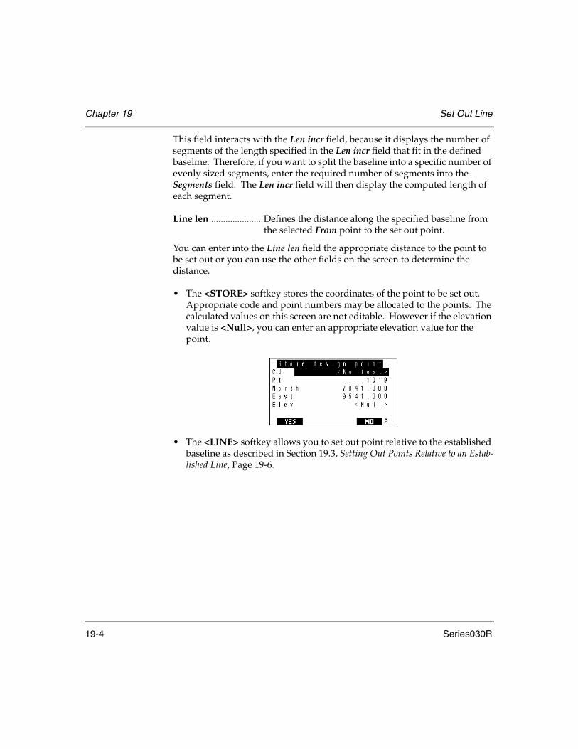
Chapter 19 Set Out Line
19-4 Series030R
This field interacts with the Len incr field, because it displays the number of segments of the length specified in the Len incr field that fit in the defined baseline. Therefore, if you want to split the baseline into a specific number of evenly sized segments, enter the required number of segments into the Segments field. The Len incr field will then display the computed length of each segment.
Line len.......................Defines the distance along the specified baseline from the selected From point to the set out point.
You can enter into the Line len field the appropriate distance to the point to be set out or you can use the other fields on the screen to determine the distance.
• The <STORE> softkey stores the coordinates of the point to be set out. Appropriate code and point numbers may be allocated to the points. The calculated values on this screen are not editable. However if the elevation value is <Null>, you can enter an appropriate elevation value for the point.
• The <LINE> softkey allows you to set out point relative to the established baseline as described in Section 19.3, Setting Out Points Relative to an Estab-lished Line, Page 19-6.

Set Out Line Chapter 19
Series030R 19-5
2. Pressing <Enter> on the Set out line screen accepts the current point on the baseline to be set out. The Series030R shows you all the information required to set out the point: the necessary horizontal and vertical angles to observe, the desired slope distance to the point, the reduced horizontal and vertical angles, and the azimuth.
3. Return to Section 18.4, Setting Out a Point, Page 18-5, for further details relating to setting out procedures.
4. Choose one of the following actions when the procedure is completed.
Table 13: Actions Available After Setout
Action Description
ESC Press <ESC> to return to setting out the plan position of the current point. This action might be necessary if the prism pole is inadvertently moved during the setting out of the elevation.
Store Press the <STORE> softkey to store the current setout position. The Series030R then prepares to store the results and shows you the point name, the code, or both. The default code includes a reference to the name of the point that was set out. When the point name and code are acceptable, press <Enter> to store a position record and a NOTE record that indicates how far offline the set out point was from the required line. A negative offline value indicates that the measure point was to the left of the required line. Press <ESC> to return to the setting out of points. Once the position record is generated, the Series030R returns to the Set out line screen so that you can choose another point to set out.
Enter Press <Enter> once a satisfactory elevation has been set out.

Chapter 19 Set Out Line
19-6 Series030R
19.3 Setting Out Points Relative to an Established Line
Once the baseline is defined, you can set out points relative to the line or offset from that line. The line is extrapolated such that any observation is described relative to the line and can be directed in order to set out along the line.
1. The following Set out line screen displays after the baseline definition is accepted:
2. Press the <LINE> softkey to set out points relative to the baseline.
3. The following screen displays:
Offset ..........................For setting out points relative to a line parallel to the defined line at the specified offset distance. A negative offset value indicates an offset to the left of the defined line.
H.obs ...........................Horizontal observation angle
V.obs............................Vertical observation angle
<POINTS> .................This softkey allows you to set out the points of the defined baseline as described in Section 19.2, Setting Out a Defined Line, Page 19-3.

Set Out Line Chapter 19
Series030R 19-7
<Enter>/<READ> .....Displays a Take reading screen:
4. Sight on the prism and initiate the appropriate reading. The following screen displays:
5. Enter value in the Target Ht field and press <Enter>.
6. Information about the observed point relative to the defined baseline is displayed.
Offline ........................Perpendicular distance from the observed point to the baseline
In/Out .........................Distance to move either in (toward the instrument) or out (away from the instrument to set the prism on the defined line
Cut/Fill........................Vertical distance from the observed point to the perpendicular intersection of the line
H.obs ...........................Horizontal observation angle
V.obs............................Vertical observation angle
S.Dist ..........................Slope distance

Chapter 19 Set Out Line
19-8 Series030R
7. Press the <READ> or <TARGET> softkey to refine your prism location. You can take as many observations to the prism as needed. After each observation, the Offline, In/Out and Cut/Fill fields are updated to reflect the latest position of the prism relative to the defined line.
8. Choose one of the following actions when the procedure is completed.
• Press <ESC> to return to setting out the plan position of the current point. This action might be necessary if the prism pole is inadvert-ently moved during the setting out of the elevation.
• Press the <STORE> softkey to store the current setout position.• Press <Enter> to store results and return to the Set out line screen.
The Series030R then prepares to store the results. It will show you a default point name and code that it will use.
Change the point name, the code or both. The default code includes a reference to the name of the point that was set out. When the point name and code are acceptable, press <Enter>. A position record will be stored. A NOTE record, indicating how far off line the set out point was from the required line, also is stored. A negative off line value indicates that the measure point was to the left of the required line.
Press <ESC> to return to the setting out of points. Once the position record is generated, the Series030R returns to the Set out line screen so that you can choose another point to set out.
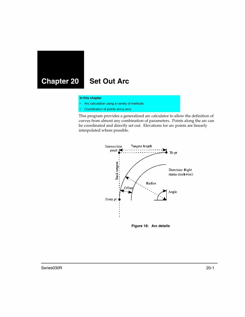
Series030R 20-1
Chapter 20 Set Out Arc
This program provides a generalized arc calculator to allow the definition of curves from almost any combination of parameters. Points along the arc can be coordinated and directly set out. Elevations for arc points are linearly interpolated where possible.
Figure 18: Arc details
In this chapter
• Arc calculation using a variety of methods
• Coordination of points along arcs

Chapter 20 Set Out Arc
20-2 Series030R
20.1 Defining Arcs
The first step in setting out arc points is to define the arc.
1. Select the Set out arc option from the COGO menu.
2. Begin with the standard station and backsight setup as described in Chapter 9, Station Setup and Backsight.
3. The Define arc screen displays. Enter the appropriate information:
Table 14: Define Arc Screen Fields
Field Description
Direction Specifies whether the arc turns right (clockwise) or left (counter clockwise) when viewed from the From point. This field toggles between Right and Left when you press the <¨> or <Æ> keys.
From (required) Enter a point from which the arc initiates in the direction defined. Note: You must enter the From field plus one of the other point fields (To pt, Center or Intersect pt). If points are specified for three of the four possible point fields, the arc details will be computed from the relationship of these points. Otherwise you can enter one of the arc definition fields (Radius, Angle, Arc len, Chord ln, Tan len or Back tan) to fully define the arc. See Figure 18, Page 20-1 for an illustration of which arc definition values you can specify. The values for the rest of the fields are calculated and displayed (except for the point fields).
To pt (optional) Describe the point upon which the arc terminates.
Center (optional) Define the center of the arc.
Radius (optional) Define the radius of the arc.
Angle (optional) Define the subtended angle.

Set Out Arc Chapter 20
Series030R 20-3
NOTE Elevations are linearly interpolated along the arc. The assumption is made that the elevations of the Center and Intersection points are equal to the elevation halfway along the arc between the To and From points, for the purposes of determining elevations. This assumption is not always true, but is a reasonable approximation.
4. Once the arc has been defined, the <CREATE> softkey will appear when the cursor is placed on any blank point field. If this softkey is selected, the computed coordinates for that point will be stored. You are given the opportunity to view the calculated coordinates and assign an appropriate code and point name to the point. If the elevation value is <Null> you are able to enter an appropriate elevation into the field. For Example, this option is useful for calculating the IP or center point of an arc.
20.2 Defining Points to Set Out
Once the arc is defined, you can set out the points which define the arc. The Set out arc screen displays after the arc is defined and the <Enter> key is pressed.
Arc len (optional) Define the distance along the arc.
Chord ln (optional) Define the straight line distance between the From and To points.
Tan len (optional) Define the tangent length.
Back tan (optional) Define the back tangent length.
Intersect pt (optional) Define the intersection of the tangents.
<READ> This softkey displays when the cursor is on any of the point name fields, to enable direct readings to be taken to establish these points if desired. If an unknown point name is entered, the Key in coords screen will appear, allowing you to enter the appropriate coordinate values.
Table 14: Define Arc Screen Fields
Field Description

Chapter 20 Set Out Arc
20-4 Series030R
The following is found on the Set out arc screen:
Offset ..........................Can be used to define a parallel offset from the originally defined curve. A negative value indicates an offset to the left; a positive value illustrates an offset arc to the right (Figure 18, Page 20-1).
Len incr.......................(Length increment) Enables you to specify the arc length (or chord length) increments around the arc at which points will be set out. For example, if you wish to set out points every 50 feet around the arc, enter 50 into this field. The <←> and <→> softkeys decrease/increase the current arc length (or chord length) to be set out by the value in the Len incr field.
∆Chordarc ..................Displays the maximum chord-to-arc separation that applies for the specified Len incr. This is useful for checking that the points to be set out around the arc will be spaced closely enough. Entering a required maximum chord-to-arc separation will result in the appropriate length increment being computed, such that this separation is achieved.
Figure 19: Chord-to-arc separation
Segments ....................The Segments field displays the number of segments, between the From and To points, into which the total arc length is split. If you set this field to 1, the total arc length (or chord length) will be displayed in the Len incr field. If you want to set out an arc that is split evenly into five sections, enter 5 into this field, and the appropriate length increment to achieve this will be displayed in the Len incr field.
Arc
Chord
Maximum chord to arc separation

Set Out Arc Chapter 20
Series030R 20-5
Arc len ........................Displays the arc length from the From point to the point to be set out. You can enter into the Arc len field the appropriate arc length to the point to be set out or you can use the other fields on the screen to determine the arc length.
<RNDUP>..................This softkey, when selected, will round the value in the Segments field up to the next whole number. This is useful where you want to set out points at even increments around an arc while ensuring that a specific maximum chord-to-arc separation is maintained. In this situation you can enter the required chord-to-arc separation into the ∆Chordarc field and then select the <RNDUP> softkey to ensure that a whole number of segments will be set out.
<CHORD> .................This softkey is pressed, the last prompt changes to Chord ln rather than Arc len and the softkey changes to <ARC>. This enables the points along the arc to be set out to achieve defined chord lengths rather than arc lengths. For example, if you want to set out points around an arc so that the chord length between the points is 50 feet, select the <CHORD> softkey and enter 50 into the Len incr field. Select the <ARC> softkey to return to defining the set out points in terms of arc lengths.
<STORE> ...................This softkey allows you to store the coordinates of calculated points along the arc. Appropriate code and point numbers may be allocated to the points. The calculated values on this screen are not editable. However, if the elevation value is <Null>, you can enter an appropriate elevation value for the point.
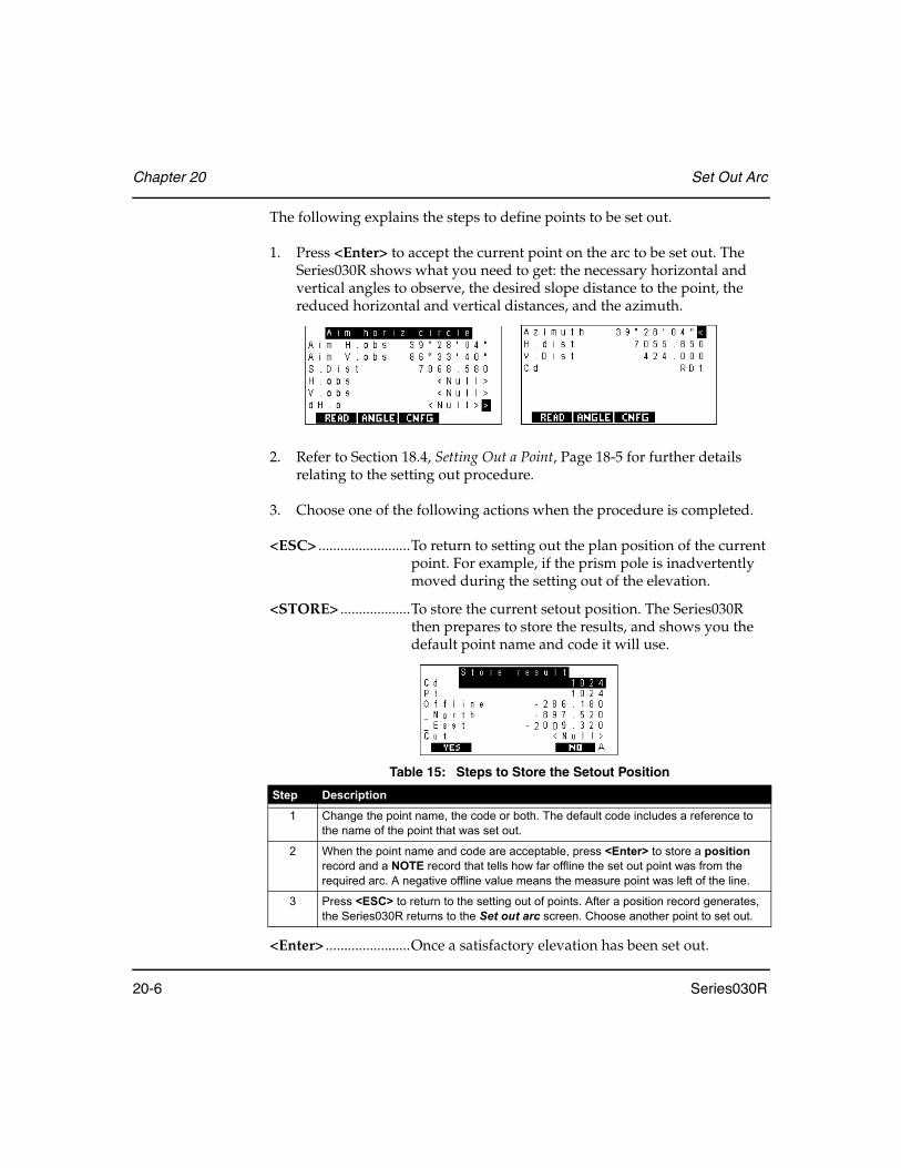
Chapter 20 Set Out Arc
20-6 Series030R
The following explains the steps to define points to be set out.
1. Press <Enter> to accept the current point on the arc to be set out. The Series030R shows what you need to get: the necessary horizontal and vertical angles to observe, the desired slope distance to the point, the reduced horizontal and vertical distances, and the azimuth.
2. Refer to Section 18.4, Setting Out a Point, Page 18-5 for further details relating to the setting out procedure.
3. Choose one of the following actions when the procedure is completed.
<ESC> .........................To return to setting out the plan position of the current point. For example, if the prism pole is inadvertently moved during the setting out of the elevation.
<STORE> ...................To store the current setout position. The Series030R then prepares to store the results, and shows you the default point name and code it will use.
<Enter> .......................Once a satisfactory elevation has been set out.
Table 15: Steps to Store the Setout Position
Step Description
1 Change the point name, the code or both. The default code includes a reference to the name of the point that was set out.
2 When the point name and code are acceptable, press <Enter> to store a position record and a NOTE record that tells how far offline the set out point was from the required arc. A negative offline value means the measure point was left of the line.
3 Press <ESC> to return to the setting out of points. After a position record generates, the Series030R returns to the Set out arc screen. Choose another point to set out.
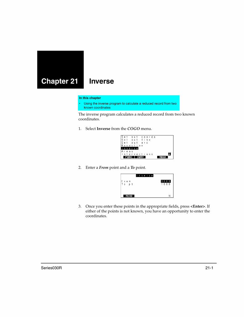
Series030R 21-1
Chapter 21 Inverse
The inverse program calculates a reduced record from two known coordinates.
1. Select Inverse from the COGO menu.
2. Enter a From point and a To point.
3. Once you enter these points in the appropriate fields, press <Enter>. If either of the points is not known, you have an opportunity to enter the coordinates.
In this chapter
• Using the inverse program to calculate a reduced record from two known coordinates

Chapter 21 Inverse
21-2 Series030R
4. Once the coordinates of both points are known, the vector between them is calculated and displayed:
5. If you press <Enter>, the data is stored in the database as a reduced (RED) record. If you do not wish to save the result, press <ESC> to exit to the menu.
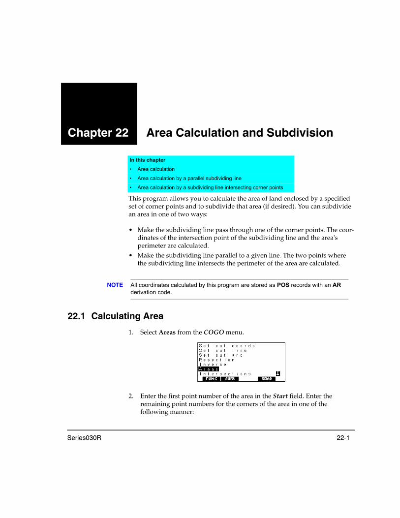
Series030R 22-1
Chapter 22 Area Calculation and Subdivision
This program allows you to calculate the area of land enclosed by a specified set of corner points and to subdivide that area (if desired). You can subdivide an area in one of two ways:
• Make the subdividing line pass through one of the corner points. The coor-dinates of the intersection point of the subdividing line and the area's perimeter are calculated.
• Make the subdividing line parallel to a given line. The two points where the subdividing line intersects the perimeter of the area are calculated.
NOTE All coordinates calculated by this program are stored as POS records with an AR derivation code.
22.1 Calculating Area
1. Select Areas from the COGO menu.
2. Enter the first point number of the area in the Start field. Enter the remaining point numbers for the corners of the area in one of the following manner:
In this chapter
• Area calculation
• Area calculation by a parallel subdividing line
• Area calculation by a subdividing line intersecting corner points
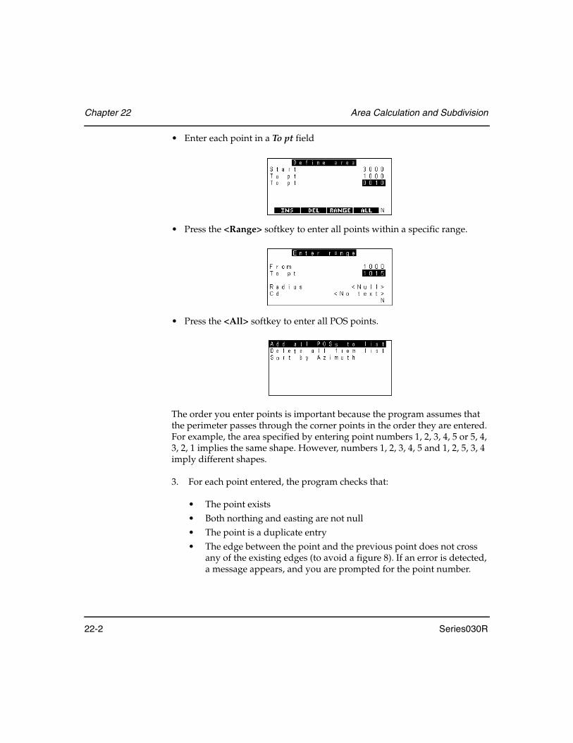
Chapter 22 Area Calculation and Subdivision
22-2 Series030R
• Enter each point in a To pt field
• Press the <Range> softkey to enter all points within a specific range.
• Press the <All> softkey to enter all POS points.
The order you enter points is important because the program assumes that the perimeter passes through the corner points in the order they are entered. For example, the area specified by entering point numbers 1, 2, 3, 4, 5 or 5, 4, 3, 2, 1 implies the same shape. However, numbers 1, 2, 3, 4, 5 and 1, 2, 5, 3, 4 imply different shapes.
3. For each point entered, the program checks that:
• The point exists• Both northing and easting are not null• The point is a duplicate entry• The edge between the point and the previous point does not cross
any of the existing edges (to avoid a figure 8). If an error is detected, a message appears, and you are prompted for the point number.

Area Calculation and Subdivision Chapter 22
Series030R 22-3
NOTE Do not enter the initial point number at the end of the list of point numbers or a duplicate point error occurs. The Areas program includes this edge implicitly.
4. Press <Enter> at the To point prompt to end point entry.
The program performs two error checks before it starts calculation:
• At least three points must be specified• The edge from the last point entered to the first point entered cannot
cross any other edges
If an error is detected, an error message displays and the To point prompt returns.
After you correct any errors, the calculation begins. When it is complete, a note record containing the area calculated and the units of the area displays. To change the units of the area, press the <Units> softkey.

Chapter 22 Area Calculation and Subdivision
22-4 Series030R
5. Press <Enter> if you want to store the record and continue with the subdivision. Extra notes are stored with the point numbers that outline the area. Press <ESC> if you want to discard the calculation. If the area is stored, a menu with the two methods of subdividing displays (for more information, see the following section).
6. Press <ESC> to exit from the program. (No note will be made.)
22.2 Subdividing by Rotating from a Fixed Point
The following screen illustrates the required field information for subdividing the area just calculated. The area is subdivided by specifying a corner point and rotating a line around the perimeter in a specified direction.
Steps for completing subdivision
1. After the area is calculated, select Fixed point subdiv and press <Enter>.
2. Enter one of the corner points in the From field.
The program enters the area from the previous calculation. The area must be greater than 0 and less than the previously calculated area of the entire polygon, if you enter a value.

Area Calculation and Subdivision Chapter 22
Series030R 22-5
3. Select Direction by toggling between Clockwise and Anticlock. After this input is complete, the point number for the point to be calculated is assigned. The calculation of its coordinates begins. A line from the given point is rotated in the given direction until the given area has been enclosed. If you see an illegal shape error, see Section 22.2.1, Illegal shape error, Page 22-5.
4. Press <Enter> to store a POS record for the calculated position or <ESC> to discard it.
22.2.1 Illegal shape error
An Illegal shape error may occur as illustrated in this example.
Two types of Illegal shape errors for the fixed point subdivision are shown here.
• If the subdivision is performed by swinging a line from Point 4 and the direction is clockwise, problems occur at Point 1. The subdividing line goes outside the perimeter.
• The second type of problem occurs if you start from Point 4 and go anti-clockwise. If the solution is between 5 and 1, part of the subdividing line lies outside the perimeter. (Similar problems occur in parallel area calcula-tions.)
If the Illegal shape error occurs, the program returns to the Subdivision menu. Otherwise the coordinates of the required point are calculated and displayed:
1 2
34
5

Chapter 22 Area Calculation and Subdivision
22-6 Series030R
22.3 Subdividing with a Line Parallel to an Existing Line
The following screen shows the information required for subdividing the area just calculated using a line parallel to an existing line.
Steps for completing the subdivision
1. After the area is calculated, select Parallel line sub and press <Enter>.
2. Specify the end points of the parallel line by entering values in the From and To pt fields. Points do not need to be corner points. Error checks are performed (see Section 22.3.1, Specify end point error checks, Page 22-6)
3. Press <Enter> to store the subdivision POS records or <ESC> to discard them.
22.3.1 Specify end point error checks
Error checks are performed on end points to see whether they exist, or that their northing and easting coordinates are nonnull. If an error is detected, a message is displayed, and the point number is prompted for again.
The program asks for the required area of the subdivision. The program will not accept it unless it is greater than 0 and less than the previously calculated area of the entire polygon. The point numbers for the points to be calculated are assigned.
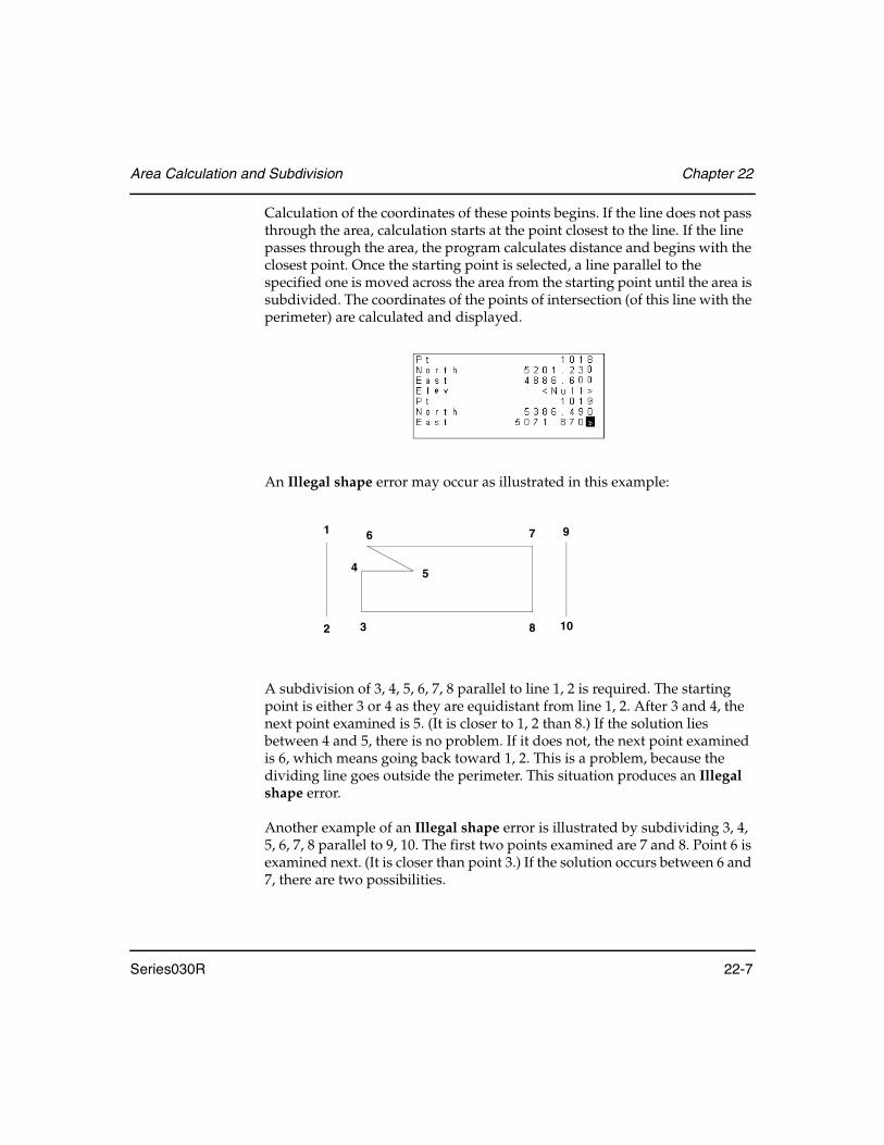
Area Calculation and Subdivision Chapter 22
Series030R 22-7
Calculation of the coordinates of these points begins. If the line does not pass through the area, calculation starts at the point closest to the line. If the line passes through the area, the program calculates distance and begins with the closest point. Once the starting point is selected, a line parallel to the specified one is moved across the area from the starting point until the area is subdivided. The coordinates of the points of intersection (of this line with the perimeter) are calculated and displayed.
An Illegal shape error may occur as illustrated in this example:
A subdivision of 3, 4, 5, 6, 7, 8 parallel to line 1, 2 is required. The starting point is either 3 or 4 as they are equidistant from line 1, 2. After 3 and 4, the next point examined is 5. (It is closer to 1, 2 than 8.) If the solution lies between 4 and 5, there is no problem. If it does not, the next point examined is 6, which means going back toward 1, 2. This is a problem, because the dividing line goes outside the perimeter. This situation produces an Illegal shape error.
Another example of an Illegal shape error is illustrated by subdividing 3, 4, 5, 6, 7, 8 parallel to 9, 10. The first two points examined are 7 and 8. Point 6 is examined next. (It is closer than point 3.) If the solution occurs between 6 and 7, there are two possibilities.
1 7
83
4
2
6 9
10
5

Chapter 22 Area Calculation and Subdivision
22-8 Series030R
The solution may be between 5 and 7; this situation presents no problem. If the solution is between 6 and 5, however, the subdividing line crosses the perimeter and an Illegal shape error results.
Although a particular area may prove to be illegal for certain subdivisions, every area can be subdivided in some way.
If an illegal shape occurs, the program returns to the Subdivision menu. Otherwise the coordinates of the required points are calculated and displayed.

Series030R 23-1
Chapter 23 Intersections
The Intersections option allows you to compute the following intersection calculations:
• Two azimuths• Azimuth and distance• Two distances
1. Select the Intersections option from the COGO menu, and the following screen is displayed:
2. Enter the first point in the Pt 1 field.
3. Select either the intersection azimuth or horizontal distance under Pt 1 by highlighting one. You can specify either an azimuth or a horizontal distance, but not both.
In this chapter
• Computing the following intersection calculations

Chapter 23 Intersections
23-2 Series030R
4. Press the <POINTS> softkey to calculate the azimuth or horizontal distance (alternatively, you can enter the value yourself). <POINTS> computes an inverse between two existing points to derive this value. One of two screens appears, either Azimuth from points or Distance from points, depending on the currently selected field. Each of these screens has From and To pt fields.
5. Enter the From and To pt values or press the <READ> softkey to read points directly. The azimuth or distance is computed. The computed value is automatically entered in the selected field on the redisplayed Intersections screen.
6. Enter the second point for the intersection calculation in the Pt 2 field. Follow Steps above to enter the intersection azimuth or distance.
NOTE As you can see from the previous steps, you can choose the type of intersection calculation by the fields you select. For example, if the azimuth fields are selected and filled in for both points, a two-azimuth intersection is computed.
7. Press <Enter> to initiate the intersection computation. The computed intersection coordinates display on a screen similar to this one:
8. If two possible intersection solutions exist (often the case with azimuth and distance and two distances), then the <OTHER> softkey appears. Select the <OTHER> softkey to display between the two solutions.

Intersections Chapter 23
Series030R 23-3
9. Complete any or none of these steps before saving:
• Set the point out by pressing the <S-O> softkey.• Assign a suitable code• Accept the auto point number in the point field or alter it• Enter an elevation for the intersected point
10. Press the <STORE> softkey or <Enter> to save the intersected point, or discard the result by pressing <ESC>. If you enter values in the Code, Pt, or Elev fields, then choose to discard the calculation result, a confirmation prompt will display. After saving or discarding the intersection point calculation, the main intersection calculation screen appears.
11. Exit from the Intersection calculations option by pressing <ESC>. The program returns to the COGO menu.
NOTE Note: In the azimuth and distance method, you cannot use the same point for the starting point for both the azimuth and the entered distance. This specification is the same as entering an azimuth and distance from the selected point. If you want to do this method, use the Key in azmth & dist function in the Keyboard input option.

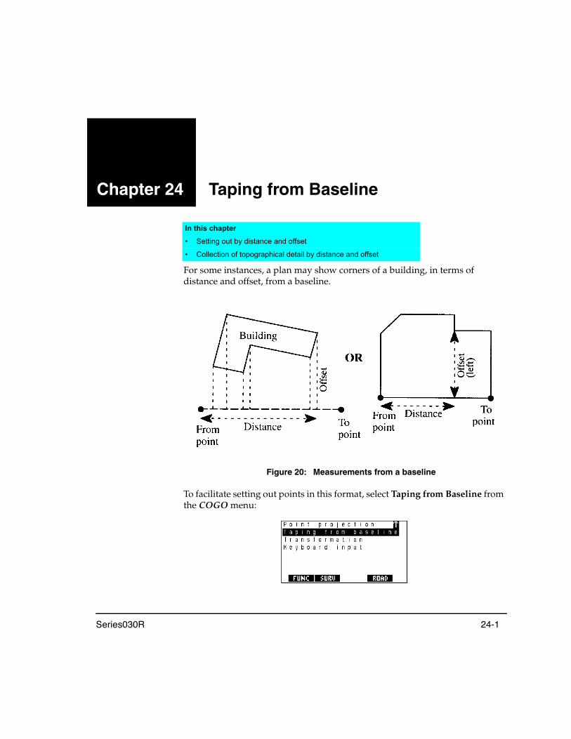
Series030R 24-1
Chapter 24 Taping from Baseline
For some instances, a plan may show corners of a building, in terms of distance and offset, from a baseline.
Figure 20: Measurements from a baseline
To facilitate setting out points in this format, select Taping from Baseline from the COGO menu:
In this chapter
• Setting out by distance and offset
• Collection of topographical detail by distance and offset

Chapter 24 Taping from Baseline
24-2 Series030R
The baseline may be defined by survey or boundary points, or two corners of the building itself. Once the two baseline points are specified, distance and offset data can be entered. The entry of the baseline definition is done in exactly the same manner as the definition of the baseline in the Set out line option. See Section 19.1, Defining the Baseline, Page 19-2, for details on the definition of the baseline.
24.1 Setting Out Points from a Baseline
When you press <Enter> after the baseline definition has been completed, you will be presented with a screen similar to the following:
Enter the appropriate set out distance along the baseline and offset from it for the point to be set out into the Dist and Offset fields, respectively. A negative offset value indicates that the point to be set out is to the left of the baseline, when viewed from the From point toward the To point. A negative distance value indicates that the point to be set out is in the opposite direction to that of the baseline (the point is “behind" the From point).
The d.Elev field can be used for specifying a known difference in elevation, from the interpolated height along the baseline to the point being set out. A negative difference in elevation value indicates the point to be set out is below the interpolated elevation along the baseline.

Taping from Baseline Chapter 24
Series030R 24-3
Select the <S-O> softkey once the distance, offset and, if desired, difference in elevation values have been entered. Initially, you will be given the opportunity to save the computed point in the Series030R SDR database (with an associated Note recording the entered distance, offset and difference in elevation values). Next, you will be presented with the standard setting out options. Refer to Section 18.4, Setting Out a Point, Page 18-5, for details relating to the setting out operation.
24.2 Establishing Coordinates from Taped Measurements
In addition to setting out points based on the specified baseline, this program also can be used for computing the coordinates of points fixed by measurement from the baseline.
In this case, the measured distance along the baseline and offset from it are entered into the Dist and Offset fields, respectively. The d.Elev field can be used for specifying the measured difference in elevation between the baseline and the fixed point. The program assumes that the difference in elevation relates to the interpolated elevation along the baseline.
Once you have entered the measured values in relation to the baseline press the <STORE> softkey. This displays the calculated coordinates for the fixed point, and allows the point name, code, and elevation (if <Null>) to be entered if desired. You can then confirm that you want to store the computed point in the Series030R SDR database (with an associated Note recording the measured distance, offset and difference in elevation values).


Series030R 25-1
Chapter 25 Point Projections
This program projects a point onto a line or arc. It calculates the distance and offset of the point relative to the specified baseline (or arc), and it computes the coordinates of the intersection point, which can then be directly set out. Elevations are interpolated where possible.
Figure 21: Point projection
In this chapter
• Projecting points onto a line or arc
• Calculating offsets to a baseline
XIntersection point
Point to project
OffsetTo pointFrom point
Distance
XIntersection point
Point to project
Offset
To pointFrom point
Distance
LINE
ARC

Chapter 25 Point Projections
25-2 Series030R
25.1 Defining Baseline/Arc
The definition of the baseline (or arc) is done using the same screens as provided in the Set out line and Set out arc options. See Section 19.1, Defining the Baseline, Page 19-2 and Section 20.1, Defining Arcs, Page 20-2 for details. An <ARC>/<LINE> softkey is provided to allow you to change between defining a baseline or arc, as appropriate, for the point projection you want to carry out.
25.2 Projecting Points
Once you have specified the baseline or arc onto which you want to project points, press <Enter> and you are presented with the Point projection screen, which allows you to specify the first point you want to project onto the defined baseline or arc.
The following is displayed on the screen:
Dist, Offset, d.Elev .......................These calculated fields are only displayed once a point number has been specified in the Pt field.
The d.Elev value is calculated using the elevation interpolated along the baseline or arc compared with the elevation of the specified point. If it is not possible to compute the d.Elev value, it will be displayed as <Null> and you will be able to enter the appropriate value if known.

Point Projections Chapter 25
Series030R 25-3
Pt .....................................................Displays the point number. If you enter a different point number into this field, a message displays asking if you wish to discard the data.
If you press the <NO> softkey, the Point projection screen appears with the point number unchanged so you can save the results. If you discard the data, the Point projection screen will be redisplayed with the projection values calculated for the new point.
<Enter> or <STORE>..................Press either to save details of the point projection carried out as Notes in the Series030R SDR database.
The point number of the projected point, along with the Dist and Offset values, are recorded in a single Note with the d.Elev value being recorded in a second Note if the value was not <Null>.
<READ> ........................................This softkey is displayed when the Pt field is selected, allowing an instrument reading to a new point to be taken directly.
If this softkey is selected, the result of the previous calculation will be saved, if applicable.
<NEXT>......................................... If you are projecting onto an arc, this softkey will appear on the Point projection screen.
If this softkey is selected, the next solution will be displayed. A second possible solution occurs when the defined arc is greater than 180° and the projection azimuth crosses it twice.
<INTERSEC> ...............................This softkey enables you to compute and save the perpendicular intersection point on the baseline or arc.
If you press the <INTERSEC> softkey, a screen similar to that shown following is displayed, which shows the computed coordinates for the intersection point.

Chapter 25 Point Projections
25-4 Series030R
You can enter an appropriate code for the point if desired and also change the point number. If the elevation for the intersection point cannot be interpolated, it is displayed as <Null> and you may enter the appropriate value if known.
Pressing <Enter> or the <STORE> softkey will save the computed intersection point in the Series030R SDR database.
<S-O>.............................................This softkey enables you to directly set out the computed intersection point. You are presented with the standard setting out options once the <S-O> softkey has been pressed. Refer to Section 18.4, Setting Out a Point, Page 18-5, for details relating to the setting out operation.

Series030R 26-1
Chapter 26 Transformations
The Series030R provides linear and Helmert transformations of survey points from one coordinate system to another. The most common application for transformation is converting a survey from site coordinates to a local projection.
The parameters for Helmert transformation are calculated using a least squares method to deal with redundant data. The northing and easting coordinate values are transformed using the computed transformation parameters; however, the elevation values are adjusted by the average elevation difference between the elevation of the control points in the proper coordinate system and the elevation of the equivalent points in the actual survey job.
The Series030R's Helmert transformation uses a separate job for each of the two coordinate systems. This reduces the chance of getting them confused. The Series030R prompts you to select a job containing points in the old coordinate system. The currently selected job acts as the destination for the newly transformed points. The easy way to remember this is that the new points are stored in the current job (as usual).
The Series030R uses a combination of translation, rotation and scaling to effect the linear transformation.
In this chapter
• Helmert transformations of job coordinates to a different coordinate system
• Linear transformations of job coordinates to a different coordinate system
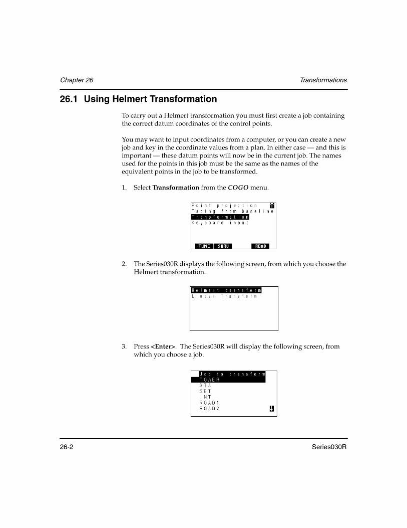
Chapter 26 Transformations
26-2 Series030R
26.1 Using Helmert Transformation
To carry out a Helmert transformation you must first create a job containing the correct datum coordinates of the control points.
You may want to input coordinates from a computer, or you can create a new job and key in the coordinate values from a plan. In either case — and this is important — these datum points will now be in the current job. The names used for the points in this job must be the same as the names of the equivalent points in the job to be transformed.
1. Select Transformation from the COGO menu.
2. The Series030R displays the following screen, from which you choose the Helmert transformation.
3. Press <Enter>. The Series030R will display the following screen, from which you choose a job.

Transformations Chapter 26
Series030R 26-3
4. Highlight the name of the job to be transformed and press <Enter>. The Series030R will search for any point names that are common to both jobs, and compare the coordinates in both jobs. It uses the coordinates of the equivalent points in the two jobs to calculate the best transformation Helmert parameters using least squares methods. Once this process is complete, the average deviation error is shown. This is a result of the least squares calculation from the redundant data supplied.
5. If the error is unacceptably large, press <ESC> to escape. Otherwise, press <Enter> to start the transformation. Each uncommon point in the old coordinate system job will be transformed and stored in the current (new coordinate system) job. This process may take some time for large jobs. Each point number is shown as it is transformed. The control points common to both jobs are not transformed, as they already exist in both jobs. This also preserves the accuracy of the control points.
26.2 Using Linear Transformation
The linear transformation also can be used to perform a translation or rotation.
1. Select Transformation from the COGO menu.

Chapter 26 Transformations
26-4 Series030R
2. The Series030R displays the following screen, from which you choose Linear transformation.
3. Press <Enter>. The Series030R will display the following screen, from which you choose a job for transformation.
4. Highlight a job and press <Enter>. The Series030R will display the following screen.
5. You can enter ∆North, ∆East, ∆Elev, and Scale values from this screen to perform a translation. You also can enter in the RotPt field a point around which to rotate. If you enter a point name in the RotPt field, the screen will change to the following:

Transformations Chapter 26
Series030R 26-5
Enter an angle value in the rotation field and press <Enter> to perform a rotation.
NOTE You can also use combinations of translations and rotations to perform linear transformations.
6. The <OPTNS> softkey will display two screens that provide other ways to enter the Delta values and the rotation. Press this softkey to display the Options Translate screen.
7. When using the Options Translate screen, you can select a point already in the destination job by entering its point name in the Pt field. If you enter a point name, the coordinates (both original and destination) will be display only and the Delta values on the main linear transformation screen will also be display only. These values can be edited if you reenter the Options Translate screen and change the point that was selected.
8. Change to the Options Rotate screen by pressing <→> and <←>. The Series030R will display the following:

Chapter 26 Transformations
26-6 Series030R
9. Enter a point around which to rotate in the RotPt field and press <Enter>. The Series030R will display the following screen, showing old and new azimuth fields.
10. If you know the old and new azimuth values enter them and press <Enter>. If you do not know the azimuths, enter From and To points and the Series030R will calculate the azimuths and enter them on the screen.
NOTE Obtaining the azimuths can be done by entering both azimuths, entering all four points, or by entering one of the azimuths and then entering the two points for the other azimuth.
11. Press <Enter> a final time to initiate the linear transformation.

Series030R 27-1
Chapter 27 Cross-Section Survey
The purpose of the Cross-Section Survey program is to survey cross-sections of roads or other linear features. The Series030R automatically calculates the offsets from an observation designated as the center line point.
This program enables you to survey the cross-sections in one of two ways:
• Walk the minimum distances (see Figure 22) • Survey from the centerline outward (see Figure 23, Page 27-2)
Figure 22: Survey cross-sections by walking the minimum distances
In this chapter
• Using the cross-section survey program to survey cross-sections of roads or existing ground details
Sta 1 + 00Left to Right
Sta 0 + 50Right to Left
Sta 0 + 00Left to Right
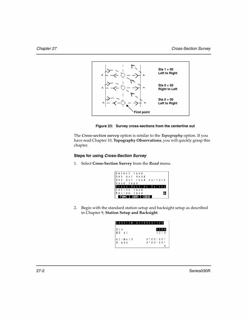
Chapter 27 Cross-Section Survey
27-2 Series030R
Figure 23: Survey cross-sections from the centerline out
The Cross-section survey option is similar to the Topography option. If you have read Chapter 10, Topography Observations, you will quickly grasp this chapter.
Steps for using Cross-Section Survey
1. Select Cross-Section Survey from the Road menu.
2. Begin with the standard station setup and backsight setup as described in Chapter 9, Station Setup and Backsight.
Sta 1 + 00Left to Right
Sta 0 + 50Right to Left
Sta 0 + 00Left to Right
First point

Cross-Section Survey Chapter 27
Series030R 27-3
3. Once you complete station and backsight details, the Series030R displays this screen:
Enter the name of the road where you are taking cross-sections in the Road field. The road name can be up to 16 characters long. Specifying a different road name in the Road field after observing some sections allows you to take cross-sections of subsequent roads.
4. Enter the station (chainage) value in the Stationing field for the first cross-section. Use the format XXXX.XXX, and the number will be displayed in the selected roading format in the Units screen accessed from the Functions menu. For example, 1000.000 displays as 10+00.000.
The Sta incr field and the <STA-> and <STA+> softkeys offer a quick means to increase or decrease the station value. This is useful if you are surveying cross-sections at even intervals. Pressing the <STA+> softkey adds the value in Sta incr to the station value to get a new station value.
Once you have completed at least one cross-section, you may chose not to specify the station value for subsequent cross-sections. If you do not specify the station value, the Series030R uses the horizontal distance between the new cross-section's centerline point and that of the last section as the station increment (This has the implicit assumption that the centerline is a straight line between the two points).
5. Use the Direction field to specify the survey direction of the cross-section. Choose from Left->Right, Right->Left, Left, or Right using the left and right arrow keys. When set to Right or Left, the direction does not toggle with each reading set.
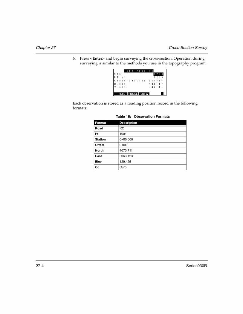
Chapter 27 Cross-Section Survey
27-4 Series030R
6. Press <Enter> and begin surveying the cross-section. Operation during surveying is similar to the methods you use in the topography program.
Each observation is stored as a roading position record in the following formats:
Table 16: Observation Formats
Format Description
Road RO
Pt 1001
Station 0+00.000
Offset 0.000
North 4070.711
East 5063.123
Elev 129.425
Cd Curb
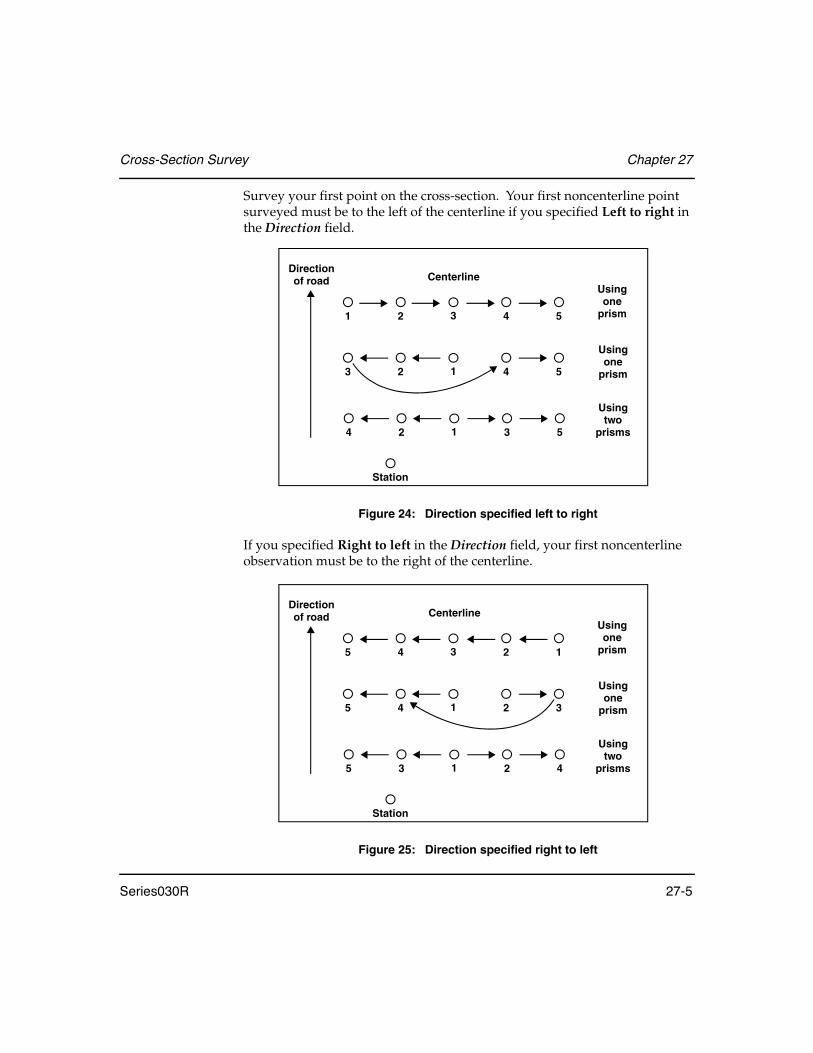
Cross-Section Survey Chapter 27
Series030R 27-5
Survey your first point on the cross-section. Your first noncenterline point surveyed must be to the left of the centerline if you specified Left to right in the Direction field.
Figure 24: Direction specified left to right
If you specified Right to left in the Direction field, your first noncenterline observation must be to the right of the centerline.
Figure 25: Direction specified right to left
1 2 3 4 5
3 2 1 4 5
4 2 1 3 5
Usingone
prism
Usingone
prism
Usingtwo
prisms
Directionof road
Station
Centerline
12345
32145
42135
Usingone
prism
Usingone
prism
Usingtwo
prisms
Directionof road
Station
Centerline
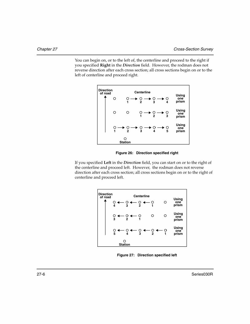
Chapter 27 Cross-Section Survey
27-6 Series030R
You can begin on, or to the left of, the centerline and proceed to the right if you specified Right in the Direction field. However, the rodman does not reverse direction after each cross section; all cross sections begin on or to the left of centerline and proceed right.
Figure 26: Direction specified right
If you specified Left in the Direction field, you can start on or to the right of the centerline and proceed left. However, the rodman does not reverse direction after each cross section; all cross sections begin on or to the right of centerline and proceed left.
Figure 27: Direction specified left
1 2 3 4
1 2 3
1 2 3 4 5
Usingone
prism
Usingone
prism
Usingone
prism
Directionof road
Station
Centerline
1234
123
12345
Usingone
prism
Usingone
prism
Usingone
prism
Directionof road
Station
Centerline

Cross-Section Survey Chapter 27
Series030R 27-7
When taking observations to the cross-section points, the Series030R needs some way of deciding whether the last point surveyed was significant (a centerline point, or the last point to be surveyed in the cross-section). After each measurement you must either press <Enter> or <READ> to continue. If you press <Enter>, the Series030R “knows” the last measurement was significant, and the following screen appears. Pressing <READ> instructs the Series030R to use the last measurement as a cross-section point and carry on to take the next reading.
If you press <Enter> by mistake, you can press <ESC> to continue taking readings.
If you have not already defined the centerline point, the Series030R decides that this is why you have pressed <Enter> and sets the centerline point to be the last surveyed point. Pressing <Enter> confirms this to be the case, and you are returned to taking cross-section measurements.
If you have already specified the centerline point, the Series030R decides that you want to leave this cross-section by pressing <Enter>. Accordingly, it sets the Finished Section field to be Yes. Pressing <Enter> now confirms that you want to finish this cross-section survey and returns to the initial screen where you can specify the new station value.
NOTE You may override the Series030R's assumptions by specifying the desired values in place of those furnished by the Series030R.
This methodology allows you the flexibility of starting at the centerline point or from one side. It also ensures identification of the centerline point.
7. When observations are saved, they initially have a <Null> offset. Press <Enter> or <ESC> to exit from the current section. At this time the Series030R calculates the offsets for each surveyed cross-section and updates the database records.
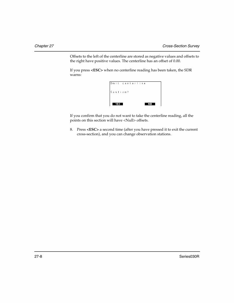
Chapter 27 Cross-Section Survey
27-8 Series030R
Offsets to the left of the centerline are stored as negative values and offsets to the right have positive values. The centerline has an offset of 0.00.
If you press <ESC> when no centerline reading has been taken, the SDR warns:
If you confirm that you do not want to take the centerline reading, all the points on this section will have <Null> offsets.
8. Press <ESC> a second time (after you have pressed it to exit the current cross-section), and you can change observation stations.

Series030R 28-1
Chapter 28 Roading
The Series030R roading program is designed for setting out urban roads and highways. It allows you to define the centerline of a road in both the horizontal and vertical planes and to attach cross-sectional templates to the centerline with superelevation (and widening) applied if desired. You can then set out any point along the road by specifying its station (chainage) and offset.
The Roading menu is available from the <ROAD> softkey:
The available options are as follows:
Select road .................................... Select an existing road with which to work
Set out road .................................. Set out points with desired stations and offsets
Set out road surface .................... Set out points relative to the computed surface of a defined road
Road topo ..................................... Perform topographical survey relative to a defined road
In this chapter
• Transferring road design to the Series030R
• Defining horizontal alignment, vertical alignment, templates, sideslopes, road cross-sections, superelevation, and widening
• Steps for setting out roads, cross-sections, and sideslopes

Chapter 28 Roading
28-2 Series030R
Cross-Section Survey.................. Survey cross-sections of roads or other linear features (see Chapter 27, Cross-Section Survey)
Define road...................................Define the horizontal and vertical alignments of the road, and its cross-section definition (which templates to use)
Review road..................................Review a road definition
Define template ...........................Create a new template or replace an existing template
Review template ..........................Review an existing template definition
28.1 Transferring Road Design to the Series030R
The roading program is not intended for road design, although this can be done. Road design typically originates from one of two sources: an office-based computer design system or a plotted design already on paper.
• If the design is in a computer, transmit it to the Series030R using a PC’s serial communications program (see Section 29.5, Direct Communications - Transferring Data Files, Page 29-7).
• If it is on paper, enter the design elements in the Series030R using the Define road option discussed in this chapter.
Figure 28: The roading process (options)
Officecomputer
Load roaddefinition
Plans
Set outroad
Key in roaddefinition byhand

Roading Chapter 28
Series030R 28-3
28.1.1 Alignment roads and string roads
The Series030R can handle two types of road definition.
• A string road is composed solely of RPOS records, each containing the position of a discrete point, described as both coordinates and station (chainage) and offset.
• An alignment road is composed of the horizontal and vertical element definitions, cross-sections, templates, super elevation and widening. These elements can be entered manually or uploaded from a computer system.
28.1.1.1 String road overview
The string road type is specifically intended to make it easy to use the output of many computerized road design packages. Because they allow roads to be defined in terms of strings that do not necessarily have a mathematical relationship to the centerline, templates cannot be used to describe the design. Instead, points at intervals along each string in the design are written as RPOS records to an SDR road file. The string name can be written to the RPOS code field.
When this string road is sent to the Series030R, you can then set out the design in terms of stationing (chainage) and offset and string name, in a similar manner to an alignment road. The main difference is that you can only set out those discrete points in the road definition. You cannot interpolate between them. You can set out a horizontal offset to the centerline if desired.
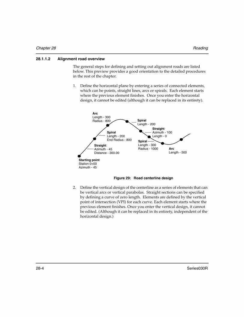
Chapter 28 Roading
28-4 Series030R
28.1.1.2 Alignment road overview
The general steps for defining and setting out alignment roads are listed below. This preview provides a good orientation to the detailed procedures in the rest of the chapter.
1. Define the horizontal plane by entering a series of connected elements, which can be points, straight lines, arcs or spirals. Each element starts where the previous element finishes. Once you enter the horizontal design, it cannot be edited (although it can be replaced in its entirety).
Figure 29: Road centerline design
2. Define the vertical design of the centerline as a series of elements that can be vertical arcs or vertical parabolas. Straight sections can be specified by defining a curve of zero length. Elements are defined by the vertical point of intersection (VPI) for each curve. Each element starts where the previous element finishes. Once you enter the vertical design, it cannot be edited. (Although it can be replaced in its entirety, independent of the horizontal design.)
ArcLength - 300Radius - 800
Starting pointStation 0+00Azimuth - 45
StraightAzimuth - 45Distance - 300.00
SpiralLength - 200End Radius - 800 Spiral
Length - 300Radius - 1000
StraightAzimuth - 100Length - 0
SpiralLength - 200
ArcLength - 500

Roading Chapter 28
Series030R 28-5
The vertical design does not have to start or finish at the same station as the horizontal design. For example, the horizontal alignment might start at a station of 100 and the VPI at a station of 90.
Figure 30: Road vertical design
3. Define templates as a series of connected points, each point relative to the previous point or relative to the centerline. A point can be vertically above or below the previous point.
4. Define cross-sections by specifying which templates are attached to specified portions of the centerline. The Series030R will interpolate between templates.
5. The superelevation definition allows you to apply superelevation and widening to the road.
Figure 31: Cross-sectional template
VIPElevation - 30Station - 100
Starting pointElevation - 25Station - (-10)
Curve Length - 30
StraightGrade
StraightGrade
VerticalCurve Vertical
Curve
End pointElevation - 20Station - 350
IPElevation - 16Station - 200Curve Length - 30

Chapter 28 Roading
28-6 Series030R
Templates are defined independently of the road so you can use a single template to define the cross-section of more than one road.
The road cross-section definition specifies which template to use on the left of the centerline and which to use on the right. The template can be changed at different stations (chainage) along the road.
Figure 32: Horizontal overview
Once a road has been defined, the road and template definitions are independent of your survey jobs, and can be deleted, loaded and transmitted without reference to any survey job. However, setting out occurs within a particular survey job (or jobs), so the road and template definitions are copied into the job to provide a record of the road definition. (If the road definition has already been copied into the job, the Series030R verifies that it is the most recent version.)
When you key in a road definition, the Series030R searches the current job to find the coordinates of any point entered.
NOTE Roads can be independent of the coordinate system you are using. If the starting point of the horizontal alignment has coordinates, the road is considered coordinated. However, you can leave the coordinates null, and the road is uncoordinated.

Roading Chapter 28
Series030R 28-7
6. Set up your instrument station in one of two ways:
• For a coordinated road, specify either the coordinates or the station and offset of the station point.
• For an uncoordinated road, you must specify a station and offset for the station point. (The road geometry cannot be related to a coordinate.) Simi-larly, the backsight point must have a known station and offset (or azi-muth).
7. Set out by selecting a road and specifying a desired station and offset. The Series030R analyzes the horizontal and vertical alignments and calculates a plan (North, East) position for the centerline at the desired station. The current template at the station is then applied normal to the centerline, and the elevation is calculated.
In addition to station and offset, you also can specify a horizontal and vertical offset. They are applied to the calculated coordinates. The vertical offset affects the elevation. The horizontal offset is applied horizontally in a direction normal to the centerline.
8. Use the same procedure for setting out design coordinates as described in Chapter 18, Set Out Design Coordinates.
28.2 Selecting/Creating a Road
To work with the roading features, you need to identify an existing road or create a new one.
Creating a new road
1. Choose Select road from the Roading menu.

Chapter 28 Roading
28-8 Series030R
2. Access the Create Road screen by pressing the <NEW> softkey.
If no roads exist within your current project, the Create Road screen displays first.
3. Enter a name, up to 16 characters. For example, you could call your road “Highway one.”
4. Confirm a projection scale factor for the road. The scale factor is for internal Series030R use, and must be the same as any job scale factor you use to set out the road or for road topo.
5. Press <Enter>.
6. Enter information in the Note screen (or leave blank), then press <Enter>.
WARNING: Roads are independent of survey jobs. They can have the same names as jobs, but this is not recommended.

Roading Chapter 28
Series030R 28-9
NOTE Once a road has been created, it is considered the “selected” road. All road programs will use it as the definition until a different road is selected.
Selecting an existing road
1. Choose Select road from the Roading menu.
2. Use the <↑> and <↓> keys to highlight the desired road and press <Enter>.
The <PGUP> and <PGDN> softkeys allow you to page through numerous roads. The <STAT> softkey is described in the following two sections.
NOTE Once a road has been selected, all road programs will use it as the definition until a different road is selected.
28.3 Accessing Road Statistics/Renaming a Road
You can display the job statistics for a road, and in the Job Statistics screen, you can rename the road.
1. Choose Select road from the Road menu.
2. Highlight the road to be accessed.

Chapter 28 Roading
28-10 Series030R
3. Select the <STAT> softkey.
4. The following fields display the following information, and only the name of the road can be modified.
ID.................................Name of the current road
Job size (k) .................(information only) Size of the job, in kilobytes, that the job currently occupies in memory.
Recs used....................(information only) Approximate number of records (point positions, observations, notes, etc.) currently stored in the job.
Date and Time...........(information only) Date and time that the job was last accessed; therefore, the date and time displayed will not necessarily relate to the last time data was saved in the job. For example, the process of selecting a job as the current job will access the job files and therefore update the date and time.
Point count.................(information only) Number of points currently stored. A new job will have a point count of 0.
5. Press <Enter> to accept changes or <ESC> to return the Select road screen.

Roading Chapter 28
Series030R 28-11
28.4 Deleting a Road/Template
After you transmit a job to a PC or printer, you can remove it from memory.
1. Select Job deletion from the Functions menu. This screen is used for the deletion of roads and templates as well as survey jobs, so you need to select what you are removing. (This selection may vary depending on what configuration you have).
2. Highlight Select roads and press <Enter>. The Series030R checks to see if there are any roads that have been transmitted and are available for deletion. If there are none, it advises you to send or print the jobs first with the following screen.
3. If roads or templates are available for deletion, a list displays. Available roads/templates are marked No; unavailable ones are marked N/A.
4. Place the cursor on the road/template you are deleting, then use the <←> or <→> keys to toggle settings from No to Yes.
5. Press <Enter> to delete the road/template.
NOTE The <ALL> softkey allows all available roads/templates to be selected for deletion.
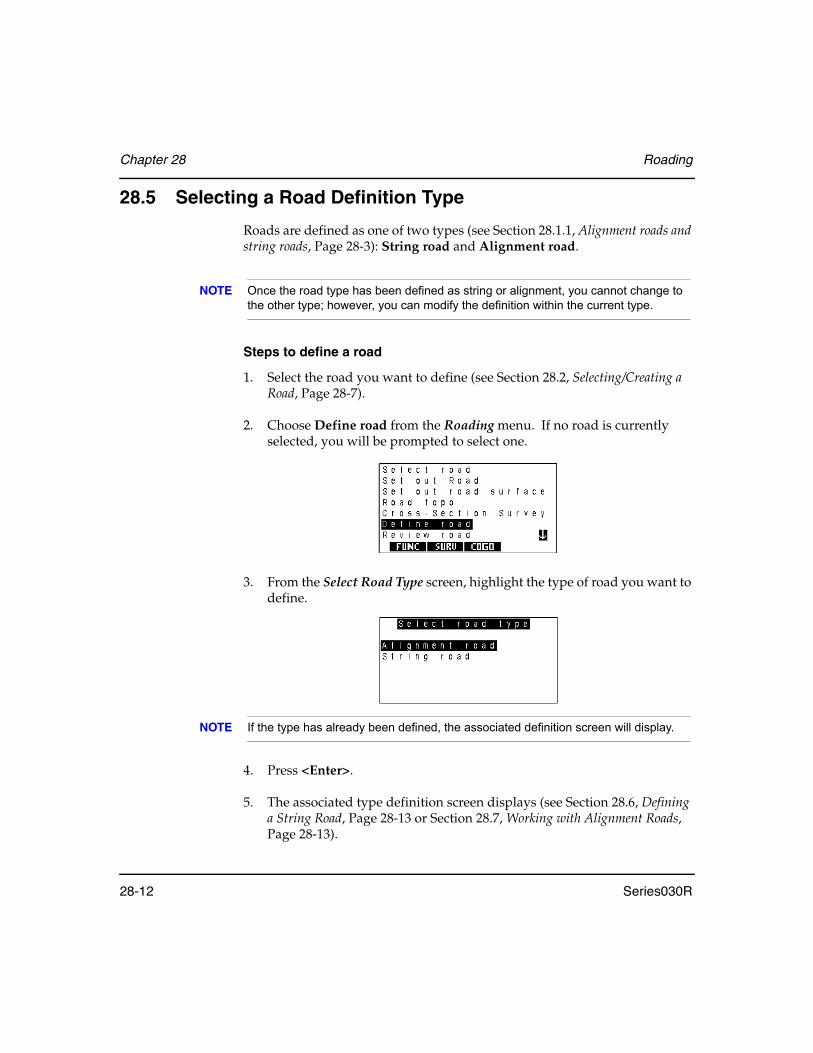
Chapter 28 Roading
28-12 Series030R
28.5 Selecting a Road Definition Type
Roads are defined as one of two types (see Section 28.1.1, Alignment roads and string roads, Page 28-3): String road and Alignment road.
NOTE Once the road type has been defined as string or alignment, you cannot change to the other type; however, you can modify the definition within the current type.
Steps to define a road
1. Select the road you want to define (see Section 28.2, Selecting/Creating a Road, Page 28-7).
2. Choose Define road from the Roading menu. If no road is currently selected, you will be prompted to select one.
3. From the Select Road Type screen, highlight the type of road you want to define.
NOTE If the type has already been defined, the associated definition screen will display.
4. Press <Enter>.
5. The associated type definition screen displays (see Section 28.6, Defining a String Road, Page 28-13 or Section 28.7, Working with Alignment Roads, Page 28-13).
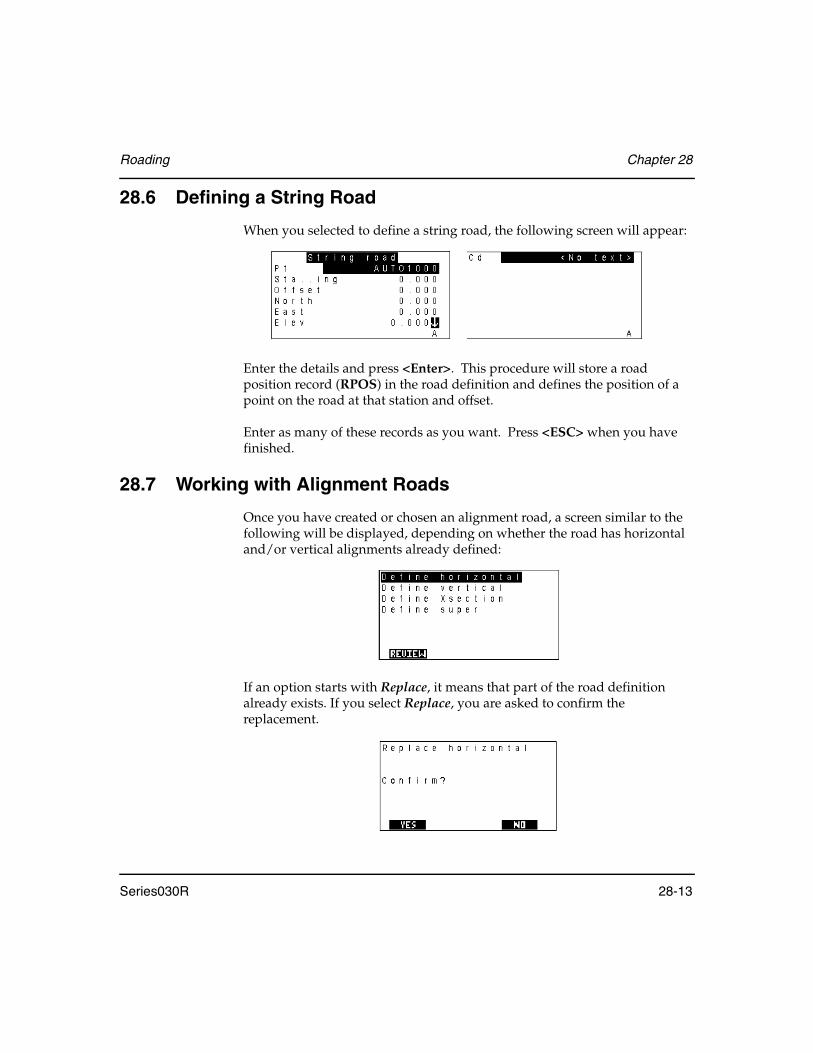
Roading Chapter 28
Series030R 28-13
28.6 Defining a String Road
When you selected to define a string road, the following screen will appear:
Enter the details and press <Enter>. This procedure will store a road position record (RPOS) in the road definition and defines the position of a point on the road at that station and offset.
Enter as many of these records as you want. Press <ESC> when you have finished.
28.7 Working with Alignment Roads
Once you have created or chosen an alignment road, a screen similar to the following will be displayed, depending on whether the road has horizontal and/or vertical alignments already defined:
If an option starts with Replace, it means that part of the road definition already exists. If you select Replace, you are asked to confirm the replacement.

Chapter 28 Roading
28-14 Series030R
Press the <REVIEW> softkey to display the road name, scale factor and any notes entered when the road was created. The road review is similar to data base review. For more information on the reviewing technique, see Chapter 6, Viewing Survey Data.
The following four sections explain how to create an alignment road. Section 28.13, Roading Calculations, Page 28-37 describes the calculations used in the above processes.
28.8 Defining a Horizontal Road Alignment
Steps for defining horizontal alignment are as follows:
1. Choose Define horizontal or Replace horizontal.
2. Enter the start point for the horizontal alignment:
The only essential information on this screen is the Stationing (chainage) field.
3. Define the station at the start of the road in the Stationing field. The value may be negative.

Roading Chapter 28
Series030R 28-15
4. Be sure the Azimuth field is a nonnull value. Although the azimuth is not essential for all calculations, if a spiral or an arc is defined next, this azimuth is used.
5. (Optional) Enter point coordinates in one of three ways: (If you do not enter coordinates, the road is uncoordinated).
• Enter a point name for the start of the centerline in the Start field and the point's coordinates are displayed in the North and East fields.
NOTE The point name is not stored in the road definition. Only the coordinates are stored because the road is independent of all survey jobs; it cannot contain any job-specific point names.)
• Enter coordinates directly into the North and East fields.• Key in coordinates to create a position (POS) record if you enter an
unknown point name in the Start or To pt fields (see Chapter 18, Set Out Design Coordinates).
6. (Optional) Enter the starting azimuth for the road centerline directly into the Azimuth field or enter a point name in the To pt field. The Series030R calculates an azimuth from the start coordinates to the point.
7. Press <Enter>to accept the screen.
If you enter a To pt, the Series030R assumes that you want to use the To pt as part of your alignment; it takes you directly to the entry of a horizontal point element (Section 28.8.1.4, Horizontal point, Page 28-20). If you do not want to include the point as part of the alignment, press <ESC>, and the Series030R displays the menu of horizontal elements (described in the next section).

Chapter 28 Roading
28-16 Series030R
28.8.1 Adding and deleting horizontal elements
Once the start point of the horizontal alignment has been defined, you will see a menu listing the four possible horizontal elements and the station (chainage) and coordinates of the end of the last element defined. (If the road is uncoordinated, then the Horz Point option is not available, and the coordinates are not displayed.)
Also displayed for your information are the coordinates, if known, and the station at the end point of the last element defined. Each element is described in the following sections. A horizontal alignment consists of any number of these elements linked together in order.
Steps for defining horizontal elements
1. Define as many elements as you want by highlighting an element in this list and pressing <Enter>. Each element is added to the end of the horizontal alignment. The definition of the four horizontal elements is covered in Section 28.8.1.1, Horizontal straight, Page 28-17 through Section 28.8.1.4, Horizontal point, Page 28-20.
2. Press the <REVIEW> softkey to review the horizontal elements in the road definition. This procedure is almost identical in layout and operation to the review of survey data using the <View> key, (see Chapter 6, Viewing Survey Data). The only difference is that it shows the road definition rather than the job data.
3. Press <UNDO> to delete the last horizontal element defined.

Roading Chapter 28
Series030R 28-17
4. Press <ESC> on the Elements menu when you have entered all the elements in your horizontal alignment. The Series030R asks you to confirm completing the alignment:
When you confirm the completion, your horizontal alignment is finalized. The four different horizontal elements are described in the next four sections.
28.8.1.1 Horizontal straight
When you choose Horz straight from the Horizontal elements menu, the following screen displays:
Stationing...................(information only) Shows you the station (chainage) at the start of the straight section.
Azimuth .....................Determines the direction of the straight. It defaults to the azimuth at the end of the previous element. If the straight is the first element in the alignment, it defaults to the starting azimuth of the centerline. Generally, you will not need to change this value. It is acceptable to do so, but the alignment will not be smooth; a sudden change of direction will occur.
Distance......................Specifies the length of the straight section.
Press <Enter> to accept the screen.
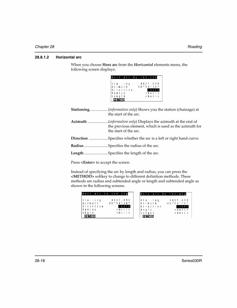
Chapter 28 Roading
28-18 Series030R
28.8.1.2 Horizontal arc
When you choose Horz arc from the Horizontal elements menu, the following screen displays:
Stationing...................(information only) Shows you the station (chainage) at the start of the arc.
Azimuth .....................(information only) Displays the azimuth at the end of the previous element, which is used as the azimuth for the start of the arc.
Direction ....................Specifies whether the arc is a left or right hand curve.
Radius .........................Specifies the radius of the arc.
Length.........................Specifies the length of the arc.
Press <Enter> to accept the screen.
Instead of specifying the arc by length and radius, you can press the <METHOD> softkey to change to different definition methods. These methods are radius and subtended angle or length and subtended angle as shown in the following screens.
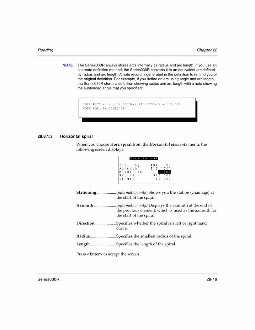
Roading Chapter 28
Series030R 28-19
NOTE The Series030R always stores arcs internally as radius and arc length. If you use an alternate definition method, the Series030R converts it to an equivalent arc defined by radius and arc length. A note record is generated in the definition to remind you of the original definition. For example, if you define an arc using angle and arc length, the Series030R stores a definition showing radius and arc length with a note showing the subtended angle that you specified:
28.8.1.3 Horizontal spiral
When you choose Horz spiral from the Horizontal elements menu, the following screen displays:
Stationing...................(information only) Shows you the station (chainage) at the start of the spiral.
Azimuth .....................(information only) Displays the azimuth at the end of the previous element, which is used as the azimuth for the start of the spiral.
Direction ....................Specifies whether the spiral is a left or right hand curve.
Radius .........................Specifies the smallest radius of the spiral.
Length.........................Specifies the length of the spiral.
Press <Enter> to accept the screen.
HORZ ARCSta..ing 82.000Dist 210.760Radius 300.000NOTE ROAngle 40515'08"

Chapter 28 Roading
28-20 Series030R
If a spiral element follows a horizontal straight or point, it is assumed to be an entry spiral, with an initial infinite radius that gradually decreases. If the spiral follows an arc, it is assumed to be an exit spiral, with its radius starting at the specified value and gradually increasing.
A spiral following another spiral is opposite that of the spiral it follows (a spiral following an entry spiral is an exit spiral, and vice versa).
28.8.1.4 Horizontal point
A horizontal point element is similar to a horizontal straight, except that it is defined by the coordinate where the element ends rather than as a continuation of the previous element. Horizontal point records are meaningful only in a coordinated road definition.
When you choose Horz point from the Horizontal elements menu, the following screen displays:
Stationing...................(information only) Shows you the station (chainage) at the end of the previous element.
Azimuth .....................(information only) Displays the azimuth at the end of the previous element.
Three ways exist to enter a point's coordinates:
• Enter the point's coordinate values in the North and East fields. A point name is not stored with the definition since the road definition is indepen-dent of any survey job.
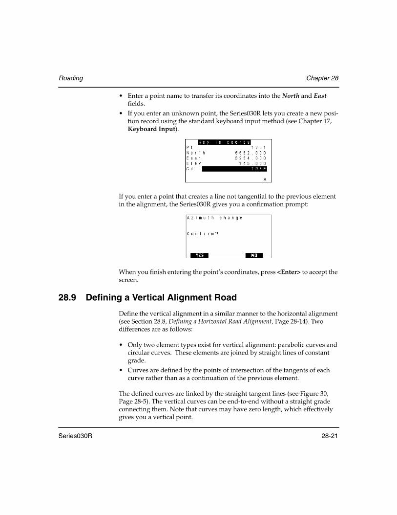
Roading Chapter 28
Series030R 28-21
• Enter a point name to transfer its coordinates into the North and East fields.
• If you enter an unknown point, the Series030R lets you create a new posi-tion record using the standard keyboard input method (see Chapter 17, Keyboard Input).
If you enter a point that creates a line not tangential to the previous element in the alignment, the Series030R gives you a confirmation prompt:
When you finish entering the point’s coordinates, press <Enter> to accept the screen.
28.9 Defining a Vertical Alignment Road
Define the vertical alignment in a similar manner to the horizontal alignment (see Section 28.8, Defining a Horizontal Road Alignment, Page 28-14). Two differences are as follows:
• Only two element types exist for vertical alignment: parabolic curves and circular curves. These elements are joined by straight lines of constant grade.
• Curves are defined by the points of intersection of the tangents of each curve rather than as a continuation of the previous element.
The defined curves are linked by the straight tangent lines (see Figure 30, Page 28-5). The vertical curves can be end-to-end without a straight grade connecting them. Note that curves may have zero length, which effectively gives you a vertical point.

Chapter 28 Roading
28-22 Series030R
28.9.1 Vertical alignment start point
Once you have chosen Define road from the Roading menu, define the vertical alignment start point.
Steps for defining the start point
1. Choose one of the Define vertical options:
If the option displays as Replace vertical, it indicates a part of the definition exists. If you choose the Replace option, you receive a prompt confirming the replacement.
2. The following screen displays:
3. Define the point by specifying the station (chainage) in the Stationing field so that the vertical alignment can be related to the horizontal alignment.
NOTE The horizontal and vertical alignments do not have to start at the same station.
4. Enter the point elevation in the Elev field. You also can enter a point name in the Start field, and the elevation appears in the Elev field. (The point name itself is not actually stored in the vertical definition since the information and survey job are independent.)

Roading Chapter 28
Series030R 28-23
5. Press <Enter> to accept the screen.The following screen then displays the element choices:
The softkeys perform the following functions:
<REVIEW> ................Displays the elements in the vertical definition for review purposes
<UNDO>....................Deletes the last vertical element defined
6. Highlight one of the element choices, then press <Enter>.
28.9.2 Parabolic vertical curves
When you select the Parabolic VC option from the Vertical alignment menu, this screen displays:
Define the intersection point (IP) and length for a parabolic curve in this screen. The direction of the curve is determined by the relative position of the previous and following IPs.
Three ways exist to define the intersection point:
• Enter values in the Stationing and Elev fields.• Enter a point in the Pt field, and the elevation appears in the Elev field.• If you enter an unknown point name, create a position (POS) record using
the standard keyboard input method (see Section 17.1, Entering Known Coordinates, Page 17-2).
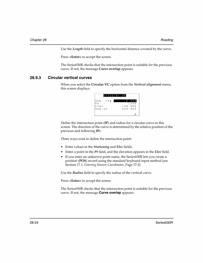
Chapter 28 Roading
28-24 Series030R
Use the Length field to specify the horizontal distance covered by the curve.
Press <Enter> to accept the screen.
The Series030R checks that the intersection point is suitable for the previous curve. If not, the message Curve overlap appears.
28.9.3 Circular vertical curves
When you select the Circular VC option from the Vertical alignment menu, this screen displays:
Define the intersection point (IP) and radius for a circular curve in this screen. The direction of the curve is determined by the relative position of the previous and following IPs.
Three ways exist to define the intersection point:
• Enter values in the Stationing and Elev fields.• Enter a point in the Pt field, and the elevation appears in the Elev field.• If you enter an unknown point name, the Series030R lets you create a
position (POS) record using the standard keyboard input method (see Section 17.1, Entering Known Coordinates, Page 17-2).
Use the Radius field to specify the radius of the vertical curve.
Press <Enter> to accept the screen.
The Series030R checks that the intersection point is suitable for the previous curve. If not, the message Curve overlap appears.
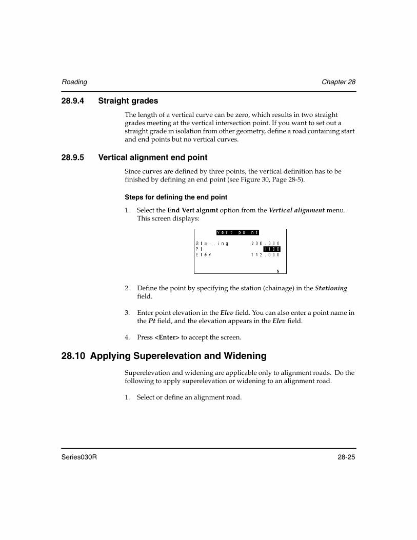
Roading Chapter 28
Series030R 28-25
28.9.4 Straight grades
The length of a vertical curve can be zero, which results in two straight grades meeting at the vertical intersection point. If you want to set out a straight grade in isolation from other geometry, define a road containing start and end points but no vertical curves.
28.9.5 Vertical alignment end point
Since curves are defined by three points, the vertical definition has to be finished by defining an end point (see Figure 30, Page 28-5).
Steps for defining the end point
1. Select the End Vert algnmt option from the Vertical alignment menu. This screen displays:
2. Define the point by specifying the station (chainage) in the Stationing field.
3. Enter point elevation in the Elev field. You can also enter a point name in the Pt field, and the elevation appears in the Elev field.
4. Press <Enter> to accept the screen.
28.10 Applying Superelevation and Widening
Superelevation and widening are applicable only to alignment roads. Do the following to apply superelevation or widening to an alignment road.
1. Select or define an alignment road.
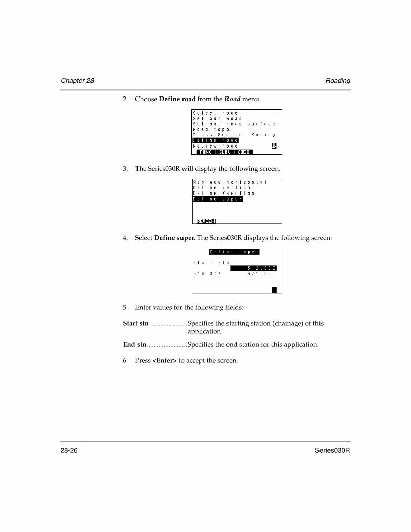
Chapter 28 Roading
28-26 Series030R
2. Choose Define road from the Road menu.
3. The Series030R will display the following screen.
4. Select Define super. The Series030R displays the following screen:
5. Enter values for the following fields:
Start stn ......................Specifies the starting station (chainage) of this application.
End stn ........................Specifies the end station for this application.
6. Press <Enter> to accept the screen.

Roading Chapter 28
Series030R 28-27
7. You can now specify the actual values of superelevation and widening to be applied at as many stations within the application as needed using the following screen:
Stationing...................Specifies the station to which these values are applied
L super ........................Specifies the superelevation to apply to the template on the left side of the road. Highlighting the L super field will display three softkeys:
• <HORIZONT> - applies horizontal superelevation to the left side of the road
• <|:> - converts a superelevation value to a ratio format (1:300)• <%> - converts the superelevation value to a percentage.
R super........................Specifies the superelevation to apply to the template on the right side of the road. Highlighting the R super field displays the same three softkeys presented for the L super field:
• <HORIZONT> - applies horizontal superelevation to the right side of the road.
• <|:> - converts a superelevation value to a ratio format (1:300)• <%> - converts the superelevation value to a percentage.
L widen.......................Specifies the amount of widening to add on to the elements of the template on the left hand side of the road
R widen ......................Specifies the amount of widening to add on to the elements of the template on the right hand side of the road
Pivot ............................Specifies whether the center, left or right part on the cross-section is to be held at constant elevation during the application of superelevation and widening
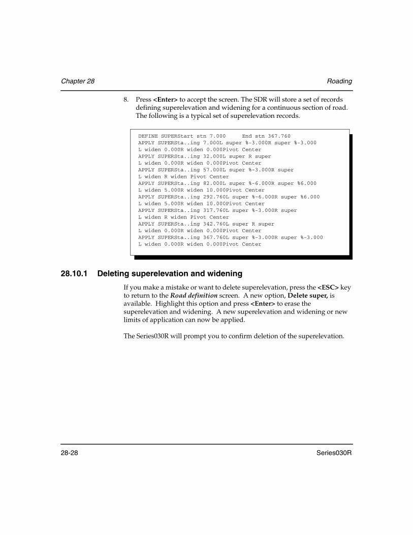
Chapter 28 Roading
28-28 Series030R
8. Press <Enter> to accept the screen. The SDR will store a set of records defining superelevation and widening for a continuous section of road. The following is a typical set of superelevation records.
28.10.1 Deleting superelevation and widening
If you make a mistake or want to delete superelevation, press the <ESC> key to return to the Road definition screen. A new option, Delete super, is available. Highlight this option and press <Enter> to erase the superelevation and widening. A new superelevation and widening or new limits of application can now be applied.
The Series030R will prompt you to confirm deletion of the superelevation.
DEFINE SUPERStart stn 7.000 End stn 367.760APPLY SUPERSta..ing 7.000L super %-3.000R super %-3.000L widen 0.000R widen 0.000Pivot CenterAPPLY SUPERSta..ing 32.000L super R super L widen 0.000R widen 0.000Pivot CenterAPPLY SUPERSta..ing 57.000L super %-3.000R super L widen R widen Pivot CenterAPPLY SUPERSta..ing 82.000L super %-6.000R super %6.000L widen 5.000R widen 10.000Pivot CenterAPPLY SUPERSta..ing 292.760L super %-6.000R super %6.000L widen 5.000R widen 10.000Pivot CenterAPPLY SUPERSta..ing 317.760L super %-3.000R super L widen R widen Pivot CenterAPPLY SUPERSta..ing 342.760L super R super L widen 0.000R widen 0.000Pivot CenterAPPLY SUPERSta..ing 367.760L super %-3.000R super %-3.000L widen 0.000R widen 0.000Pivot Center
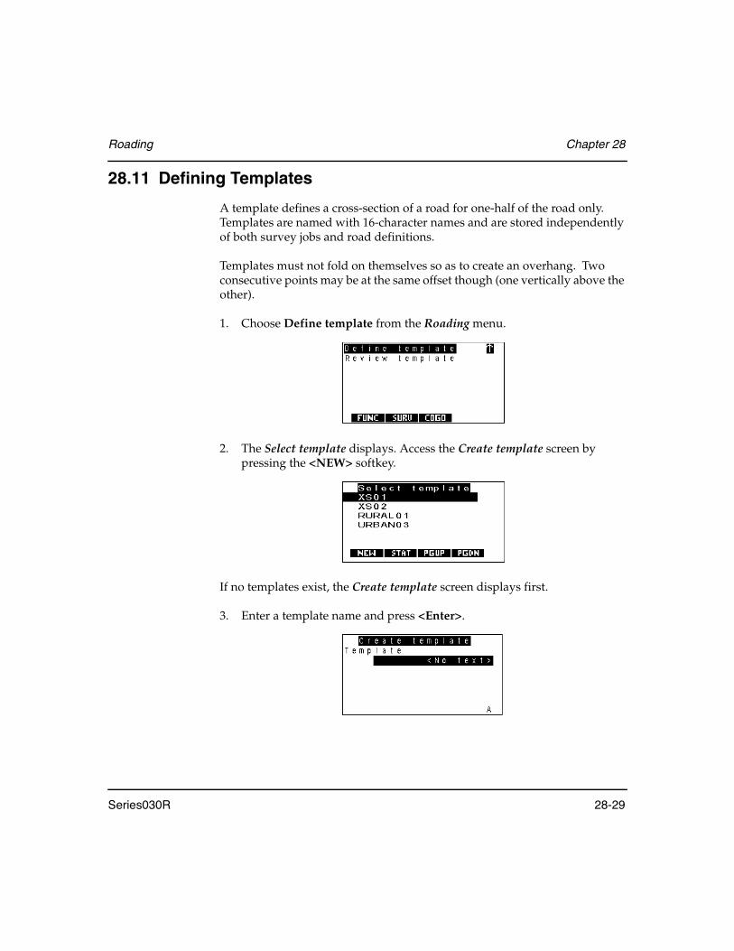
Roading Chapter 28
Series030R 28-29
28.11 Defining Templates
A template defines a cross-section of a road for one-half of the road only. Templates are named with 16-character names and are stored independently of both survey jobs and road definitions.
Templates must not fold on themselves so as to create an overhang. Two consecutive points may be at the same offset though (one vertically above the other).
1. Choose Define template from the Roading menu.
2. The Select template displays. Access the Create template screen by pressing the <NEW> softkey.
If no templates exist, the Create template screen displays first.
3. Enter a template name and press <Enter>.
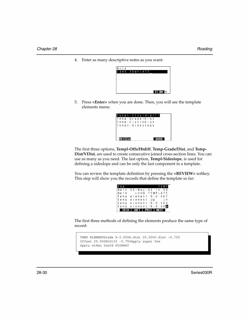
Chapter 28 Roading
28-30 Series030R
4. Enter as many descriptive notes as you want:
5. Press <Enter> when you are done. Then, you will see the template elements menu:
The first three options, Templ-Offs/Htdiff, Temp-Grade/Dist, and Temp-Dist/VDist, are used to create consecutive joined cross-section lines. You can use as many as you need. The last option, Templ-Sideslope, is used for defining a sideslope and can be only the last component in a template.
You can review the template definition by pressing the <REVIEW> softkey. This step will show you the records that define the template so far:
The first three methods of defining the elements produce the same type of record:
TEMP ELEMENTGrade %-3.000H.dist 25.000V.dist -0.750Offset 25.000HtDiff -0.750Apply super YesApply widen YesCd HIGHWAY

Roading Chapter 28
Series030R 28-31
Note also that these first three methods allow different methods of definition. The Series030R will also calculate the values not entered, all of which can be seen in review:
The grade may be specified as either a percentage “%” or as a ratio “1:” and will be displayed in printed output and review in the same format as it is entered.
Figure 33: Template elements
28.11.1 Template point by offset and height difference
When you select the Temp-Offs/Htdiff option, this screen displays:
Use this screen to define a template point by specifying the offset and the height difference relative to the centerline.

Chapter 28 Roading
28-32 Series030R
Enter appropriate values for the following fields:
Offset ..........................Specifies the distance of the point from the centerline. This offset must not be less than the offsets of any previous points in the template. (A template may not fold back on itself with an overhang.)
You can enter an offset the same as the previous point; this results in a vertical portion of the template. However, only two consecutive template points may have the same offset; you may not have three points one above the other.
HtDiff .........................Specifies the vertical height difference of the point from the centerline. A positive height difference means the point is above the centerline.
Apply Super ..............Can be set to Yes if superelevation should be applied.
Apply Widen .............Should be set to Yes if widening should be applied.
Cd ................................Is the code to be used for points set out at this point.
Press <Enter> to accept the screen.
The defined point is joined to the previous template point to form the shape of the template.
28.11.2 Template point by grade and distance
When you select the Temp-Grade/Dist option, you will see this screen:

Roading Chapter 28
Series030R 28-33
This screen defines a template point by a grade and horizontal distance from the previous template point.
Grade ..........................Specifies the grade of the element; it can be specified as Horizontal by pressing the <HORIZ> softkey, or to be a vertical up or down by pressing the <VERT> softkey and selecting the <UP> or <DWN> softkey.
The <%> and <1:> softkeys can be used to specify whether the grade is entered and displayed as a percentage or a ratio. If the format is percentage, the grade value specifies the slope to the next template point as a percentage. For example, 3% means that the template will rise 0.300 over a distance of 10.0. If the format is ratio, the grade value specifies the slope as a ratio. For example, 1:30 means that the template will rise 0.333 over a distance of 10.0.
Distance......................Specifies the horizontal distance of the new template point from the previous template point. It may not be negative; the template shape may not double back on itself. If the grade is specified as either Up or Dwn then the distance is taken to be vertical with the horizontal distance being zero.
Apply Super ..............Specifies whether or not the element will be affected by the application of superelevation.
Apply Widen .............Specifies whether or not the element will be affected by the application of widening.
Cd ................................Enables a code to be attached to the point that this element defines.
The screen is accepted automatically when you press <Enter>.
The defined point can be considered to be joined to the previous template point in order to form the shape of the template.

Chapter 28 Roading
28-34 Series030R
28.11.3 Template point by distance and vertical distance
When you select the Temp-Dist/VDist option you will see this screen:
This screen defines a template point by distance and height difference relative to the previous template point.
Enter appropriate values for the following fields:
Dist ..............................Specifies the horizontal distance of the point from the previous template point. This distance must not be negative.
VDist...........................Specifies the vertical height difference of the point from the previous template point. A positive value means the point is above the previous point, a negative value means it is below.
Apply Super ..............Can be set to Yes if superelevation should be applied.
Apply Widen .............Should be set to Yes if widening should be applied.
Cd ................................Is the code to be used for points set out at this point.
The screen will be accepted automatically when you press <Enter>.
The defined point can be considered to be joined to the previous template point in order to form the shape of the template.
28.11.4 Template sideslope definition
Define as many template points as necessary to form the shape of the template. When you have finished, define sideslopes to join the edge of the template and the existing terrain at a catch point.

Roading Chapter 28
Series030R 28-35
When you choose Templ-Sideslope, this screen displays:
Define a cut grade and a fill grade in this screen. When you are setting out the road, the Series030R determines whether you are in cut or fill and uses the appropriate grade to set out the sideslope.
Define grades like you did in the Temp-Grade/Dist template point definition (Section 28.11.2, Template point by grade and distance, Page 28-32). However, the numbers are always positive. Cut grades are assumed to rise as they get further from the centerline, and fill grades are assumed to fall.
Cut ...............................This grade will be applied to meet existing terrain when the template is in a cut situation
Fill ...............................This grade will be applied to meet existing terrain when the template is in a fill situation
Press <Enter> to accept the screen.
28.12 Defining Road Cross-Section
The cross-section of a road is defined by specifying templates to be applied along the horizontal and vertical alignments.
Templates are defined independently of any survey job or road definition. The road cross-section definition allows you to associate one or more templates with a road's horizontal and vertical alignment.
NOTE As roads are interpolated between defined cross-sections, you must have a cross-section defined at both the start and the end of a road.

Chapter 28 Roading
28-36 Series030R
Steps to define cross-sections
1. Choose Define road from the Road menu.
2. Choose Define Xsection from the Define road menu. Use this screen to define the templates that will be used for a portion of the road:
3. Specify the station (chainage) that the templates will be applied from in the Stationing field.
4. Specify the name of the template for this cross-section of the road in the left and right template fields. Type the name in the fields or press the <SEL> softkey to see a list of templates to select from. If you enter the name of a template that does not exist, you are given the option of creating it. You can enter the same name in both fields, which produces a symmetrical cross-section.
5. Press <Enter> to accept the screen.
Roading Chapter 28
Series030R 28-37
Once you have defined a cross-section for a road, the Define road menu has two options, Add Xsection and Replace Xsection.
Specify as many cross-section screens as you wish, using the Add Xsection option from the Define road menu. Cross-sections do not have to be defined in order of station (although it is more logical to do so); the Series030R sorts them so that they appear in correct sequence. The simplest procedure is to define one cross-section screen with a station equal to the start station of the road and the same at the end; this applies the same templates all the way down the road.
If you choose the Replace Xsection option from the Define road menu, all your existing cross-section definitions (but not your templates) are discarded, allowing you to define new ones.
28.13 Roading Calculations
This section describes the calculations performed to calculate positions on the road.
28.13.1 Superelevation calculation
The default superelevation applied at any station is null. Values other than the default can only be achieved between the values specified by the DEFINE SUPER record. The values of superelevation between the Start and End stations specified in the DEFINE SUPER record are calculated by referring to the APPLY SUPER records, and using linear interpolation to calculate the values of superelevation for stationing whose values do not appear explicitly in any APPLY SUPER record.
For example, using the values in the printout, Station 57.000 will have values of 3.000% and -3.000% for the left and right superelevation respectively. Interpolation will only occur between specified values. If this cannot be done then the default is given.
The calculations for the left and right hand sides of the road are completely independent of each other.
28.13.2 Widening calculation
Calculations for widening are similar to those for superelevation, the main difference being that zero is the default value for widening.

Chapter 28 Roading
28-38 Series030R
28.13.3 Template calculation
Templates are calculated outward from the centerline. They are always calculated at a particular station (chainage) and have applied to them the values of superelevation and widening defined at that station.
Each element of the template is evaluated individually, applying the values of superelevation and widening.
The normal crossfall of an element on a template is the grade that is specified in the Temp-Grade/Dist definition, or the grade derived form one of the distance based definitions. Similarly, the normal distance of an element is the distance specified in any of these definitions and is the horizontal distance of the element.
The way that superelevation is applied to the elements of a template is dependent on where in the template the element is. The first element in a template that can have superelevation applied to it will have its grade altered to be the same as the value of superelevation. Subsequent elements on the template that can have superelevation applied have their grades calculated by adding on to them the difference in grade that the first element undergoes.
The calculation process of the grade is shown by the following decision chart:
Figure 34: Calculation process decision chart
Is the super NULL?
No
Is this element subjectto super?
Yes
Is this the first element of the template?
No
Normal crossfall + super difference
Yes
No
Normal crossfall
Yes
Super

Roading Chapter 28
Series030R 28-39
Once the grade of the element is determined, the horizontal distance is calculated. The horizontal distance is the normal distance plus widening if the element is subject to widening. If the element is widened then the widening occurs by extending the element at its calculated grade. All grade calculations are carried out using grades expressed as percentages, even though these values may be entered and displayed as ratios.
NOTE Calculating a template using the default values of superelevation and widening will give the same results as would be given if all elements of the template were defined to have neither applied.
28.13.4 Pivot calculation
The pivot point is the fixed point in terms of which the cross-sections are calculated when superelevation is applied. If the pivot point is defined as “center," the centerline is held. Should the pivot point be defined as “left" or “right," the pivot calculation will find the last element of the template on that side of the road which can be subject to superelevation and uses the end of that element as the pivot point.
The position of the pivot point relative to the centerline is calculated without superelevation being applied and held fixed. After superelevation has been applied to the cross-section, the whole superelevated cross-section is raised or lowered until it is anchored on the pivot point.
28.13.5 Cross-section calculation
The cross-section at a given station (chainage) is calculated by reference to the cross-section definition and to the templates to which it refers. Interpolation between the templates in adjacent cross-section records occurs. Interpolation is based on the end of each corresponding element of the two templates concerned.
For the cross-section to be calculated, there must be a XSEC record defined both before and after the station being calculated. The cross-section can then be made up one element at a time by evaluating the same element in both templates and interpolating between them.
This interpolation is based on the differences in horizontal and vertical distances of the ends of the individual elements.
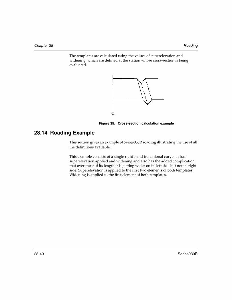
Chapter 28 Roading
28-40 Series030R
The templates are calculated using the values of superelevation and widening, which are defined at the station whose cross-section is being evaluated.
Figure 35: Cross-section calculation example
28.14 Roading Example
This section gives an example of Series030R roading illustrating the use of all the definitions available.
This example consists of a single right-hand transitional curve. It has superelevation applied and widening and also has the added complication that over most of its length it is getting wider on its left side but not its right side. Superelevation is applied to the first two elements of both templates. Widening is applied to the first element of both templates.

Roading Chapter 28
Series030R 28-41
The superelevation and widening diagrams used are shown, as are the two templates used.
Figure 36: Example road horizontal alignment
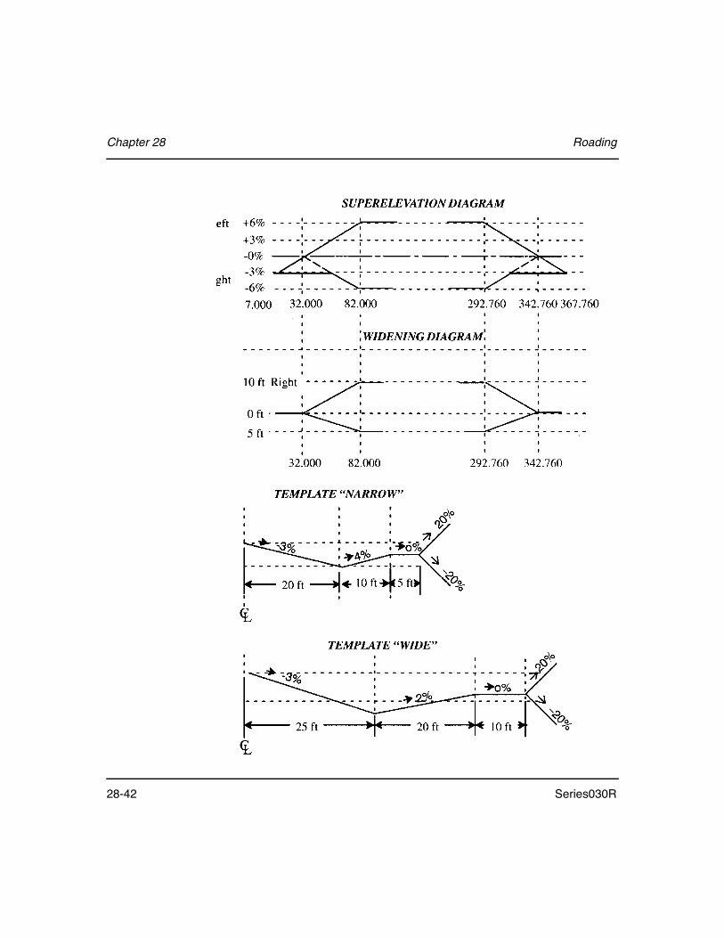
Chapter 28 Roading
28-42 Series030R

Roading Chapter 28
Series030R 28-43
SDR33 V04-04.20 10-Apr-96 08:48Angle DegreesDist FeetPress Inch HgTemp FarenhtCoord N-E-ElevROAD KIID MANUAL ROADSCALES.F. 1.00000000NOTE TS09-Apr-92 10:11HORZ ALIGNStart stn 0.000End stn 422.760Azimuth 342-43'00"North 10324.430East 84342.540HORZ STRAIGHTSta..ing 0.000Azimuth 342-43'00"Dist 32.000HORZ SPIRALSta..ing 32.000Dist 50.000Radius 300.000HORZ ARCSta..ing 82.000Dist 210.760Radius 300.000HORZ SPIRALSta..ing 292.760Dist 50.000Radius 300.000HORZ STRAIGHTSta..ing 342.760Azimuth 32-31'05"Dist 80.000VERT ALIGNSta..ing 0.000Elev 33.000VERT POINTSta..ing 500.000Elev 33.000X SECTIONSta..ing 0.000Left temp NARROWRight temp NARROWX SECTIONSta..ing 82.000Left temp NARROWRight temp NARROWX SECTIONSta..ing 292.760Left temp WIDERight temp NARROWX SECTIONSta..ing 500.000Left temp WIDERight temp NARROWDEFINE SUPERStart stn 7.000End stn 367.760APPLY SUPERSta..ing 7.000L super %-3.000R super %-3.000L widen 0.000R widen 0.000Pivot CenterAPPLY SUPERSta..ing 32.000L super R super L widen 0.000R widen 0.000Pivot CenterAPPLY SUPERSta..ing 57.000L super R super %-3.000L widen R widen Pivot CenterAPPLY SUPERSta..ing 82.000L super %6.000R super %-6.000L widen 5.000R widen 10.000Pivot CenterAPPLY SUPERSta..ing 292.760L super %6.000R super %6.000L widen 5.000R widen 10.000Pivot CenterAPPLY SUPERSta..ing 317.760L super R super %-3.000L widen R widen Pivot CenterAPPLY SUPERSta..ing 342.760L super R super L widen 0.000R widen 0.000Pivot CenterAPPLY SUPERSta..ing 367.760L super %-3.000R super %-3.000L widen 0.000R widen 0.000Pivot CenterTEMPLATE KIID NARROWNOTE TS09-Apr-92 10:15TEMP ELEMENTGrade %-3.000H.dist 20.000V.dist -0.600Offset 20.000HtDiff -0.600Apply super YesApply widen YesCd HIGHWAYTEMP ELEMENTGrade %4.000H.dist 10.000V.dist 0.400Offset 30.000HtDiff -0.200Apply super YesApply widen NoCd EDGE OF ROADTEMP ELEMENTGrade HorizontalH.dist 5.000V.dist 0.000Offset 35.000HtDiff -0.200Apply super NoApply widen NoCd SIDEWALK

Chapter 28 Roading
28-44 Series030R
28.15 Setting Up Road Station
Whenever Road topo, Set out road, or Set out road surface are selected, a road station must be set up:
The station setup is similar to standard topography; however, you can specify the station point or the backsight point relative to the road definition. The Set up on coords field is toggled between the following:
Yes................................Enters the station details in exactly the same way as described in Chapter 9, Setting up station and backsight
No ................................Sets your instrument on a point relative to the road definition with unknown coordinates
TEMP-SIDESLOPECut %20.000 Fill %20.000TEMPLATE KIID WIDENOTE TS09-Apr-92 10:17TEMP ELEMENTGrade %-3.000H.dist 25.000V.dist -0.750Offset 25.000HtDiff -0.750Apply super YesApply widen YesCd HIGHWAYTEMP ELEMENTGrade %2.000H.dist 20.000V.dist 0.400Offset 45.000HtDiff -0.350Apply super YesApply widen NoCd EDGE OF ROADTEMP ELEMENTGrade HorizontalH.dist 10.000V.dist 0.000Offset 55.000HtDiff -0.350Apply super NoApply widen NoCd SIDEWALKTEMP-SIDESLOPECut %20.000Fill %20.000

Roading Chapter 28
Series030R 28-45
When you enter a point ID into the Stn field, the following displays:
The fields on this screen are the same as those described in Chapter 9, Setting up station and backsight, except for the Sta..ing and Offset fields. These two fields will reflect the Set Up On Coords settings by displaying Northing and Easting or Stat..ing and Offset. Pressing <Enter> will store a road station record (RSTN) and return to the Confirm orientation screen.
If a backsight point is entered for which an azimuth is not found, you are asked to supply a backsight as displayed below:
The Key in azimuth and Key in coords options are the same as for normal station setup. The Key in Stn & Offset option allows you to specify a point relative to the road definition as displayed below:
ROAD STN RO 8001Sta..ing 57.000Offset -61.340North 10361.907East 84266.834Elev 35.640Road MANUAL ROADTheo ht 5.650Cd End of existing

Chapter 28 Roading
28-46 Series030R
Press <Enter> to accept this screen; a road position record is stored and the backsight reading is taken in the normal way.
NOTE For uncoordinated roads, the station position must be specified by station and offset. The backsight may not be specified by coordinates.
28.16 Setting Out Roads
The Series030R roading program is designed for setting out a road once it has been defined. You can set out any point along the road by specifying its station and offset. The following diagram shows the available options and the processes of setting out specific points:
ROAD POS KI 8002Sta..ing 32.000Offset 0.000North 10354.985East 84333.033Elev 36.130 Cd CL
Road Setting Out (28.16)
Select roadBacksight Select point to set out
Setting out Cross-Section (28.16.1)Sight instrumentTake readingAdjust prism/apply horiz offsetAccept plan point
Store record Apply vertical offset
Setting out Sideslope (28.16.2)Sight instrumentTake readingAdjust prismApply horizontal offsetApply vertical offsetAccept catch point
Sight instrumentTake readingAdjust prism locationAccept position
Return Store record Results
Results Store record Return
Staking Notes/Storing Results (28.16.3)Observing staking notesStore results

Roading Chapter 28
Series030R 28-47
1. Select road. Select the Set out road option from the Road menu. If a road has not yet been selected a list of roads available for setting out is displayed:
Highlight the road you want to select, then press <Enter>.
2. Backsight. Take backsight reading or confirm orientation.
3. Identify and select point to set out. The Set out Road screen is displayed.
Move along stationing Move between stationing
Move between
control pointsincrementally
cross-section nodes
Use the first and last softkeys to access the following navigation modes
Set out road
<INCR>/<CPT>
<STA>/<Node>
Chapter 28 Roading
28-48 Series030R
This screen allows you to select a point to set out. You may navigate to the desired point by using the softkeys. Three methods of navigating are available:
• Moving along the stationing incrementally by a set amount (<INCR> softkey at right) using the <STA+> and <STA-> softkeys
• Moving along the stationing between control points (<CPT> softkey at right) using the <NEXT> and <PREV> softkeys.
• Moving between nodes on the cross-section (<NODE> softkey at left) using the <←> and <→> softkeys.
The softkeys perform the following functions:
<STA>/<NODE> ......Toggles between the modes of moving along stationing or of moving between nodes on the cross-section. This softkey reflects the current mode. To change mode, press this softkey.
<INCR>/<CPT> ........Toggles between the modes of moving along stationing. This softkey reflects the current mode. To change modes, press this softkey.
<STA+>/<STA-> ......(in INCR mode) Increases or decreases the stationing by a set amount, determined by the Sta incr field.
<NEXT>/<PREV>....(in CPT mode) Increases or decreases the stationing between control points.
A control point is the start or end of any straight, arc, spiral, vertical curve, or the high or low point of a vertical curve. The intersection points of the vertical curves also are control points.
<→> .............................(in NODE mode) Increases the offset to the next point in the template. An increase is a move to the right (viewed looking down the road in the direction of increasing stationing).
<←> .............................(in NODE mode) Decreases the offset to the previous point in the template.

Roading Chapter 28
Series030R 28-49
The fields on the Set out Road screen are as follows:
Sta incr.......................(available only in INCR mode) Enables you to input the amount by which the stationing will increment or decrement using the <STA+> or <STA-> softkeys.
Stationing...................(information only) Displays the current stationing. This may not be less than the start station of the road or greater than the end station.
Offset ..........................Enables you to directly enter a fixed offset. Once you have entered a value into this field, the offset will not change until the <←> or the <→> softkey is pressed or a value is entered into the code field.
Cd ................................Displays the code as entered in the template definition if the point specified is the end point of that element. It will display the following under certain conditions:
• L Sideslope specifies the endpoint of the left sideslope element (the left catch point).
• R Sideslope specifies the endpoint of the right sideslope element (the right catch point).
• Undef offset occurs where a value is entered into the Offset field for which there is no design elevation, such as off the edge of the road.
• Offset occurs when a value is entered into the Offset field which is not the end point of an element of the template.
Elevation ....................Automatically calculates the elevation on the road at the specified station and offset. However, you may override this value by entering your own elevation.
Horz o/s ......................Specifies an extra horizontal offset that is to be applied to the point. Use this field to set out stakes for the edge of the road; for example, to add a safety margin to the edge of the road.
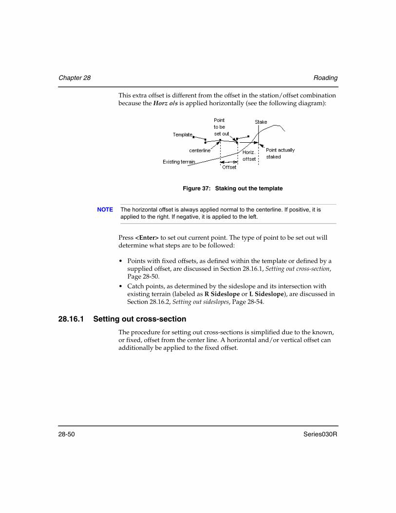
Chapter 28 Roading
28-50 Series030R
This extra offset is different from the offset in the station/offset combination because the Horz o/s is applied horizontally (see the following diagram):
Figure 37: Staking out the template
NOTE The horizontal offset is always applied normal to the centerline. If positive, it is applied to the right. If negative, it is applied to the left.
Press <Enter> to set out current point. The type of point to be set out will determine what steps are to be followed:
• Points with fixed offsets, as defined within the template or defined by a supplied offset, are discussed in Section 28.16.1, Setting out cross-section, Page 28-50.
• Catch points, as determined by the sideslope and its intersection with existing terrain (labeled as R Sideslope or L Sideslope), are discussed in Section 28.16.2, Setting out sideslopes, Page 28-54.
28.16.1 Setting out cross-section
The procedure for setting out cross-sections is simplified due to the known, or fixed, offset from the center line. A horizontal and/or vertical offset can additionally be applied to the fixed offset.

Roading Chapter 28
Series030R 28-51
Steps for setting out cross-sections
1. Sight instrument. The Series030R displays all the information required to set out the point:
The previous screen shows you the necessary horizontal and vertical angles to observe, and the desired slope distance to the point. It also shows you the reduced horizontal and vertical distances and the azimuth for your information.
Align your instrument to the horizontal angle shown. The Series030R is put into countdown mode automatically to help you. Rotate the instrument until the countdown reaches zero, then direct the prism pole in line.
2. Take reading. When ready, press the <READ> softkey to initiate the first reading.
3. Adjust prism/apply horizontal offset location. A guidance screen displays to direct the prism to the target point by providing corrections to the last reading. A horizontal offset may be applied by entering a value in the Horiz O/S field.
Left/Right ...................(information only) Displays the distance to move left or right to get on line (from the instrument operator's point of view).
In/Out .........................(information only) Shows you the distance to move in (toward the instrument) or out (away from the instrument) to get the prism on the target point.

Chapter 28 Roading
28-52 Series030R
Aim H.obs ..................Shows you the horizontal angle that you should be observing on your instrument. This changes if you change the Horz o/s field.
H.Obs..........................(information only) Indicates the horizontal observation angle
V.obs............................(information only) Indicates the vertical observation angle
S.Dist ..........................(information only) Indicates the slope distance
Horz o/s ......................Shows the horizontal offset adjustment that you entered earlier. If modified, all other fields are adjusted accordingly.
Use the <READ> or the <TARGET> softkeys to take as many observations to the prism as needed to locate the point. After each observation, the Left/Right and In/Out fields are updated to reflect the latest position of the prism relative to the point to be set out.
4. Accept plan point. Once you have located the plan view position of the point, you can continue with one of the following steps:
• Store a record and return to the Set out Road screen. Pressing <RPOS> will store a RPOS record, containing the station and offset (and coordi-nates if known) on the final observed point. A NOTE record containing the cut/fill and differences in northing and easting from the design point also is stored. When completed, Series030R will return to the Set out Road screen.
NOTE If a horizontal offset was used, the offset point is taken as the design point.
• Apply a vertical offset. To apply a vertical offset, press <Enter> and con-tinue with the next section. To access the Store Results screen, a vertical offset or zero must be applied.
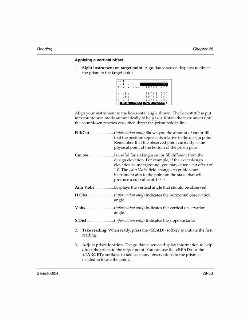
Roading Chapter 28
Series030R 28-53
Applying a vertical offset
1. Sight instrument on target point. A guidance screen displays to direct the prism to the target point.
Align your instrument to the horizontal angle shown. The Series030R is put into countdown mode automatically to help you. Rotate the instrument until the countdown reaches zero, then direct the prism pole in line.
Fill/Cut........................(information only) Shows you the amount of cut or fill that the position represents relative to the design point. Remember that the observed point currently is the physical point at the bottom of the prism pole.
Cut o/s .........................Is useful for staking a cut or fill different from the design elevation. For example, if the exact design elevation is underground, you may enter a cut offset of 1.0. The Aim V.obs field changes to guide your instrument aim to the point on the stake that will produce a cut value of 1.000.
Aim V.obs...................Displays the vertical angle that should be observed.
H.Obs..........................(information only) Indicates the horizontal observation angle.
V.obs............................(information only) Indicates the vertical observation angle.
S.Dist ..........................(information only) Indicates the slope distance.
2. Take reading. When ready, press the <READ> softkey to initiate the first reading.
3. Adjust prism location. The guidance screen display information to help direct the prism to the target point. You can use the <READ> or the <TARGET> softkeys to take as many observations to the prism as needed to locate the point.

Chapter 28 Roading
28-54 Series030R
4. Accept point. Once a satisfactory elevation has been set out, you can choose one of the following options:
• Store a record and return the Set out Road screen. Pressing the <RPOS> softkey will store a roading position record (RPOS), containing the station and offset (and coordinates if known) on the final observed point. A NOTE record containing the cut/fill and differences in northing and east-ing from the design point also is stored. When completed, Series030R will return to the Set out Road screen.
• Store results. Pressing <Enter> will take you to the Store Results screen (see Section 28.16.3, Staking notes/storing results, Page 28-57)
28.16.2 Setting out sideslopes
The procedure for setting out a left or right sideslope (the Cd field will indicate L Sideslope or R Sideslope) is different from setting out a point with a know, or fixed, offset from the center line. The Series030R cannot determine the offset to the toe of the sideslope because it does not have a model of the underlying terrain. The Series030R, therefore, allows any point on the sideslope to be located and set out using an iterative process of taking observations along the sideslope and, using the observation as a model of the underlying terrain, provides direction to the calculated toe from the current point.
Steps for setting out a sideslope
1. Sight instrument. The Series030R cannot yet give an indication of where to aim your instrument; it does not yet know anything about the terrain in the vicinity of the sideslope.
You will be prompted to take a reading as shown below:
This reading will be used by the Series030R to determine whether the sideslope is in cut or in fill; therefore, the prism should be located near the anticipated catch point.
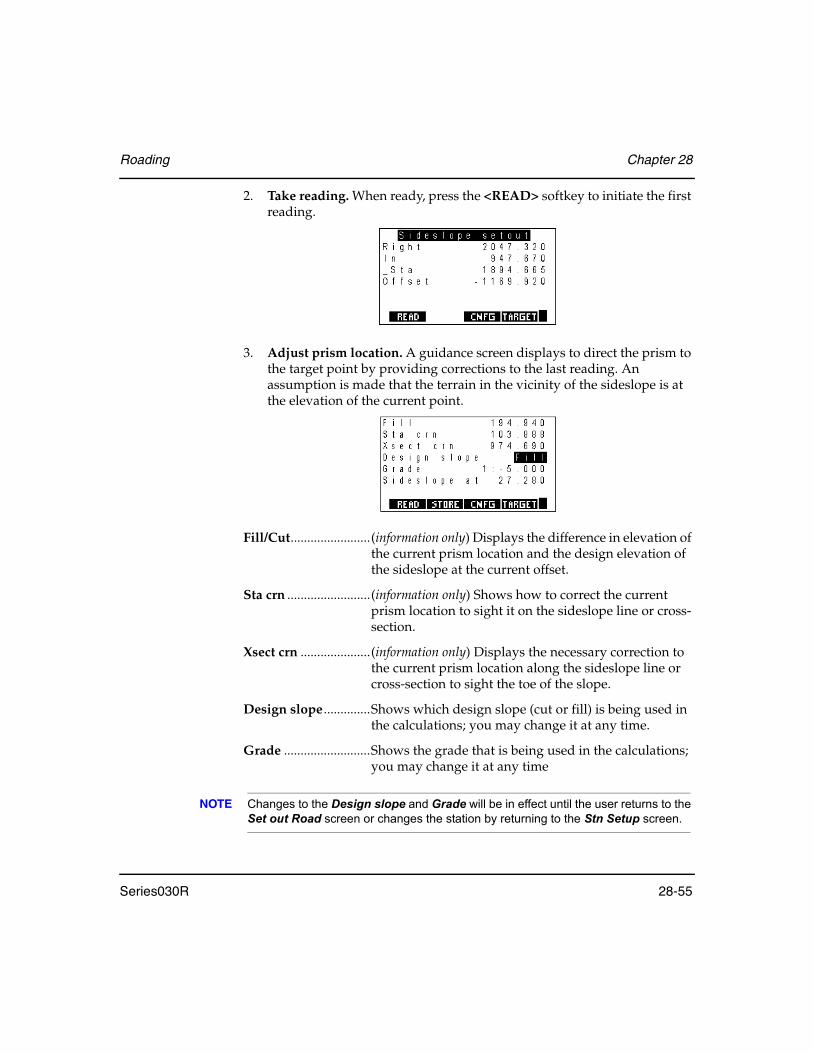
Roading Chapter 28
Series030R 28-55
2. Take reading. When ready, press the <READ> softkey to initiate the first reading.
3. Adjust prism location. A guidance screen displays to direct the prism to the target point by providing corrections to the last reading. An assumption is made that the terrain in the vicinity of the sideslope is at the elevation of the current point.
Fill/Cut........................(information only) Displays the difference in elevation of the current prism location and the design elevation of the sideslope at the current offset.
Sta crn .........................(information only) Shows how to correct the current prism location to sight it on the sideslope line or cross-section.
Xsect crn .....................(information only) Displays the necessary correction to the current prism location along the sideslope line or cross-section to sight the toe of the slope.
Design slope ..............Shows which design slope (cut or fill) is being used in the calculations; you may change it at any time.
Grade ..........................Shows the grade that is being used in the calculations; you may change it at any time
NOTE Changes to the Design slope and Grade will be in effect until the user returns to the Set out Road screen or changes the station by returning to the Stn Setup screen.

Chapter 28 Roading
28-56 Series030R
Sideslope at ...............(information only) Displays the horizontal distance from the beginning of the sideslope to the current prism location.
The Horz o/s field does not appear. The horizontal offset is not applied until the position on the sideslope to be set out has been determined.
NOTE The toe of the sideslope is the point at which the Cut/Fill is zero and the Stn crn field is zero.
You may adjust your prism location according to the corrections on the previous screen. As many readings as is necessary now may be taken by pressing the <READ> or the <TARGET> softkeys, using the values displayed to assist in determining where to move.
4. Apply horizontal offset. You may a apply a horizontal offset as described in Section 28.16.1, Setting out cross-section, Page 28-50 or press <Enter> to accept a zero offset and continue.
5. Apply vertical offset. You may apply a vertical offset as described in Applying a vertical offset, Page 28-53, or press <Enter> to accept a zero offset and continue.
6. Accept catch point. When you have either found the toe of the sideslope or have determined to set out some other point on the sideslope, you can proceed with one of the following options:
• Store a record and return the Set out Road screen. Pressing the <RPOS> softkey will store a RPOS record, containing the station and offset (and coordinates if known) on the final observed point. A NOTE record with the cut/fill and differences in northing and easting from the design point also is stored. When completed, Series030R will return to the Set out Road screen.
• Store results. Pressing <Enter> will take you to the Store Results screen.

Roading Chapter 28
Series030R 28-57
28.16.3 Staking notes/storing results
After completing the set out steps for a cross-section or a sideslope, the Store results screen gives you the opportunity to access the staking notes report and/or to store the results before returning to the Set out Road screen. The following screen displays:
The softkey functions are described in the following sections. The fields in the Store results screen display the following information:
Cd ................................Displays the code as entered in the template definition if the point specified is the end point of that element. You can modify this field.
Pt ..................................Displays the point to be used for storing results. You can modify this field.
Delta Sta .....................(information only) Displays the stationing difference between the point set out and the design point.
Delta Offset ...............(information only) Displays the offset difference between the point set out and the design point.
Fill/Cut........................(information only) Displays the vertical difference between the point set out and the design point.
28.16.3.1 Staking notes
Access to a staking notes report is provided from the Store Results screen via the <RPT> softkey. The format of the staking notes can be changed with the <OPTNS> softkey.
<RPT> .........................Enables access to a series of staking notes for each node on the cross-section.
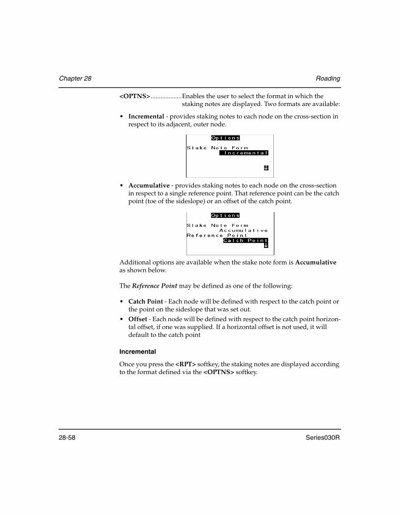
Chapter 28 Roading
28-58 Series030R
<OPTNS> ...................Enables the user to select the format in which the staking notes are displayed. Two formats are available:
• Incremental - provides staking notes to each node on the cross-section in respect to its adjacent, outer node.
• Accumulative - provides staking notes to each node on the cross-section in respect to a single reference point. That reference point can be the catch point (toe of the sideslope) or an offset of the catch point.
Additional options are available when the stake note form is Accumulative as shown below.
The Reference Point may be defined as one of the following:
• Catch Point - Each node will be defined with respect to the catch point or the point on the sideslope that was set out.
• Offset - Each node will be defined with respect to the catch point horizon-tal offset, if one was supplied. If a horizontal offset is not used, it will default to the catch point
Incremental
Once you press the <RPT> softkey, the staking notes are displayed according to the format defined via the <OPTNS> softkey.

Roading Chapter 28
Series030R 28-59
Consider a template with nodes representing the center, bottom of curb, top of curb, edge of road, and the sideslope. The Incremental option gives the slope staking notes for each node with respect to the next outer node as seen on following four screens:
Accumulative
The Accumulative option gives the slope staking notes of each node with respect to the sideslope node as displayed on the following four screens:
If the reference point was set to offset, each node would be defined with respect to the catch point offset (if supplied).
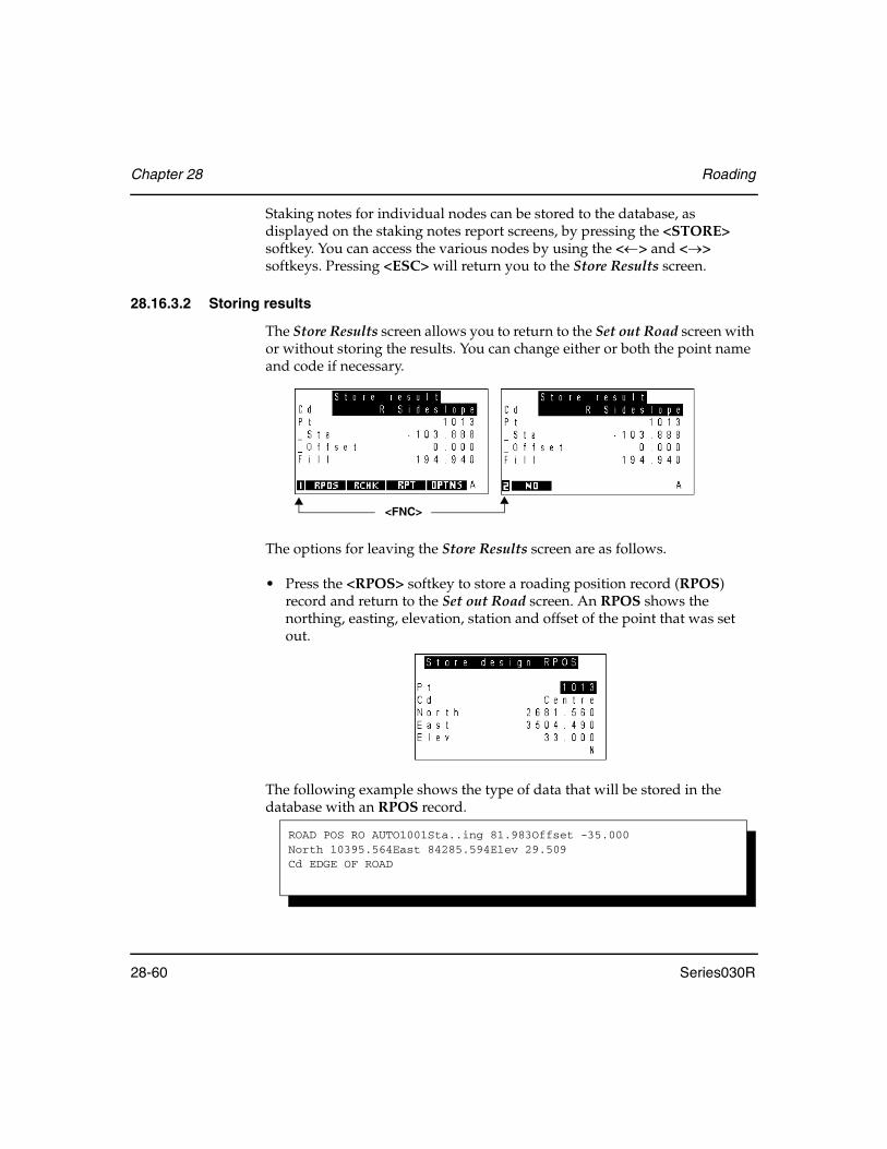
Chapter 28 Roading
28-60 Series030R
Staking notes for individual nodes can be stored to the database, as displayed on the staking notes report screens, by pressing the <STORE> softkey. You can access the various nodes by using the <←> and <→> softkeys. Pressing <ESC> will return you to the Store Results screen.
28.16.3.2 Storing results
The Store Results screen allows you to return to the Set out Road screen with or without storing the results. You can change either or both the point name and code if necessary.
The options for leaving the Store Results screen are as follows.
• Press the <RPOS> softkey to store a roading position record (RPOS) record and return to the Set out Road screen. An RPOS shows the northing, easting, elevation, station and offset of the point that was set out.
The following example shows the type of data that will be stored in the database with an RPOS record.
<FNC>
ROAD POS RO AUTO1001Sta..ing 81.983Offset -35.000 North 10395.564East 84285.594Elev 29.509Cd EDGE OF ROAD

Roading Chapter 28
Series030R 28-61
• Press the <RCHK> softkey to store a roading check record (RCHK) and return to the Set out Road screen. An RCHK record shows the differences of station, offset and elevation from the design point.
The following example shows the type of data that will be stored in the database with an RCHK record.
NOTE Note: For either type of record, an additional note is stored, giving the cut/fill and the differences in northing and easting.
• If you want to return to setting out, press <ESC>. You will be returned to the Aim Horiz Circle screen. This might be necessary if the prism pole is inadvertently moved during the setting out of the elevation.
• Press <FNC> to access the second page of softkeys and press the <NO> softkey to return to the Set out Road screen without storing any results.
Upon returning to the Set Out Road screen, you will be prompted for the next point to set out.
28.17 Using Road Topography
The road topography program allows you to take a number of readings to points and to apply station (chainage) and offset to them. Setting up for road topo is identical to setting up for setting out a road.
After you have successfully set up your station, you will be asked to take a reading to the point to apply stationing to:
ROAD CHK RO AUTO1002Sta..ing 82.000d.Chn -0.017Offset -35.000d.Offset 0.252Elev 29.509d.Elev -2.091Cd EDGE OF ROAD
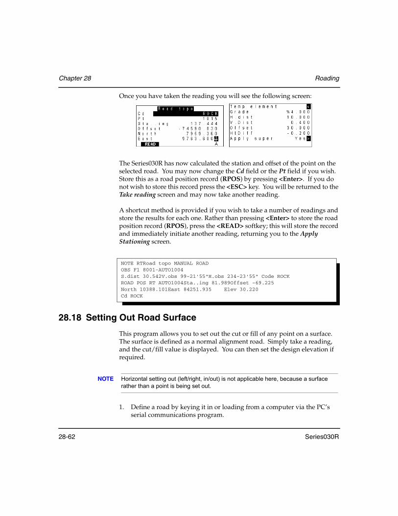
Chapter 28 Roading
28-62 Series030R
Once you have taken the reading you will see the following screen:
The Series030R has now calculated the station and offset of the point on the selected road. You may now change the Cd field or the Pt field if you wish. Store this as a road position record (RPOS) by pressing <Enter>. If you do not wish to store this record press the <ESC> key. You will be returned to the Take reading screen and may now take another reading.
A shortcut method is provided if you wish to take a number of readings and store the results for each one. Rather than pressing <Enter> to store the road position record (RPOS), press the <READ> softkey; this will store the record and immediately initiate another reading, returning you to the Apply Stationing screen.
28.18 Setting Out Road Surface
This program allows you to set out the cut or fill of any point on a surface. The surface is defined as a normal alignment road. Simply take a reading, and the cut/fill value is displayed. You can then set the design elevation if required.
NOTE Horizontal setting out (left/right, in/out) is not applicable here, because a surface rather than a point is being set out.
1. Define a road by keying it in or loading from a computer via the PC’s serial communications program.
NOTE RTRoad topo MANUAL ROADOBS F1 8001-AUTO1004S.dist 30.542V.obs 99-21'55"H.obs 234-23'55" Code ROCKROAD POS RT AUTO1004Sta..ing 81.989Offset -69.225 North 10388.101East 84251.935 Elev 30.220 Cd ROCK
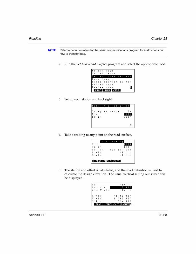
Roading Chapter 28
Series030R 28-63
NOTE Refer to documentation for the serial communications program for instructions on how to transfer data.
2. Run the Set Out Road Surface program and select the appropriate road.
3. Set up your station and backsight.
4. Take a reading to any point on the road surface.
5. The station and offset is calculated, and the road definition is used to calculate the design elevation. The usual vertical setting out screen will be displayed.

Chapter 28 Roading
28-64 Series030R
At this point you can store the result or set out the design elevation. Further readings are assumed to be to the same point, as the elevation is set out. Press the following softkeys or hardware keys to initiate the described action:
<Enter> .......................Accesses the result screen
<ESC> .........................Exits setting out road surface
<READ> .....................(softkey) Takes another reading to the same point without entering code, point number, or target height
<TARGET> ................(softkey) Takes a reading with a new target height
<CNFG> .....................(softkey) Accesses the Configure reading screen (see Section 4.2.4, Configure reading, Page 4-6)
<STORE> ...................(softkey) Stores an (RPOS) record, containing the station, offset, and coordinates of the point
The d.Sta and d.Offset fields show the distance that the prism pole has moved since the first reading to the current point. Usually this will be small, and confirms that the prism has not moved during the elevation staking procedure. However, this can also be used to set the stake away from the actual point, perhaps out of the way of heavy machinery.
Once the result record has been stored, you may take a reading to the next point on the surface (Step 4).
The station and offset is calculated by an “apply station" algorithm, which may take several seconds on a road with many elements.
If the point observed is not on the surface, you will see a <Null> cut/fill value.

Series030R 29-1
Chapter 29 Communications
This chapter gives you instructions and settings for transferring data using the Communication option on the Function menu. For example, you can send and receive survey information to and from a PC, and print data in a formatted report.
By using a PC’s serial communications program, you can transfer data files between the PC and the Series030R memory, and convert SDR files into file formats that are compatible with commonly-used CAD packages.
For example, in North America, the serial communication program is typically HyperTerminal, located on the Start menu at Programs | Accessories | Communications. Refer to your PC’s documentation for more information on using this program.
NOTE You can also transfer data between the Series030R and a PC using the Card menu and Dial-up options on the Functions menu: see Section 4.2.14, Card menu, Page 4-35 or see Section 4.2.13, Dial-up, Page 4-21.
29.1 Setting Communication Parameters
All of the Series030R’s direct communications to the memory use serial connections. The Series030R's serial port is a small, round Hirose connector. Use this connector to directly connect to a PC or serial printer.
In this chapter:
• Setting communications parameters
• Specifying output and CSV parameters
• Converting files
• Transmitting data to a computer
• Receiving computer data
• Printing data
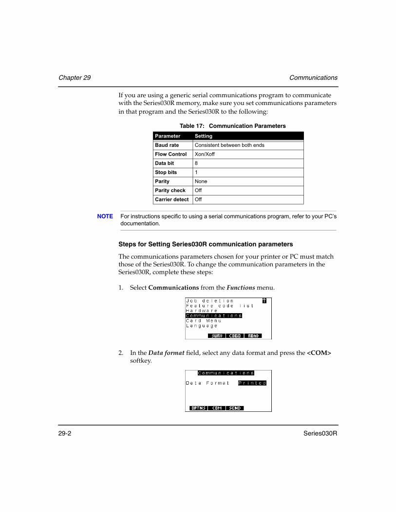
Chapter 29 Communications
29-2 Series030R
If you are using a generic serial communications program to communicate with the Series030R memory, make sure you set communications parameters in that program and the Series030R to the following:
NOTE For instructions specific to using a serial communications program, refer to your PC’s documentation.
Steps for Setting Series030R communication parameters
The communications parameters chosen for your printer or PC must match those of the Series030R. To change the communication parameters in the Series030R, complete these steps:
1. Select Communications from the Functions menu.
2. In the Data format field, select any data format and press the <COM> softkey.
Table 17: Communication Parameters
Parameter Setting
Baud rate Consistent between both ends
Flow Control Xon/Xoff
Data bit 8
Stop bits 1
Parity None
Parity check Off
Carrier detect Off
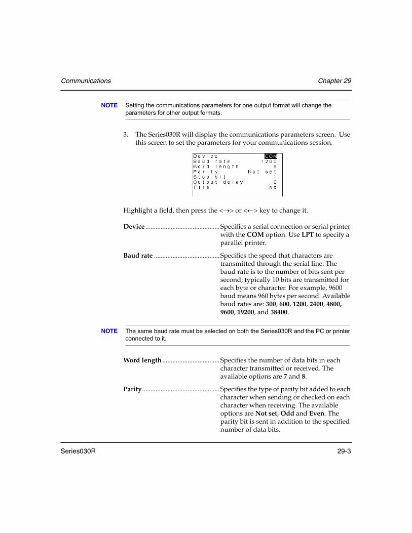
Communications Chapter 29
Series030R 29-3
NOTE Setting the communications parameters for one output format will change the parameters for other output formats.
3. The Series030R will display the communications parameters screen. Use this screen to set the parameters for your communications session.
Highlight a field, then press the <→> or <←> key to change it.
Device ............................................ Specifies a serial connection or serial printer with the COM option. Use LPT to specify a parallel printer.
Baud rate .......................................Specifies the speed that characters are transmitted through the serial line. The baud rate is to the number of bits sent per second; typically 10 bits are transmitted for each byte or character. For example, 9600 baud means 960 bytes per second. Available baud rates are: 300, 600, 1200, 2400, 4800, 9600, 19200, and 38400.
NOTE The same baud rate must be selected on both the Series030R and the PC or printer connected to it.
Word length .................................. Specifies the number of data bits in each character transmitted or received. The available options are 7 and 8.
Parity.............................................. Specifies the type of parity bit added to each character when sending or checked on each character when receiving. The available options are Not set, Odd and Even. The parity bit is sent in addition to the specified number of data bits.

Chapter 29 Communications
29-4 Series030R
Stop bits ........................................ Specifies the number of stop bits transmitted after each character. The options are 1 and 2.
Output delay ................................Gives support for serial printers with little or no buffering. When you enter number other than 0, the output will pause for the number of milliseconds specified before sending each byte. For example, 10 pauses the Series030R for 10 milliseconds before it sends each character in the output file.
4. Press <Enter> to save your settings.
29.2 Specifying the output format of observations
Records in the SDR database can be output with the same formats in which they can be viewed (see Section 6.5, Reviewing Observation Records, Page 6-5).
Steps for specifying data formats
Complete the following procedure to specify an output format:
1. On the Series030R, select Communications from the Functions menu.
2. Set the Data Format field to SDR.

Communications Chapter 29
Series030R 29-5
3. Use the <OPTIONS> softkey to specify the view for output. When you press this softkey the Series030R displays:
4. Select any of the following options to designate transfer procedures:
• Individual views - Set the views you want to Yes (current, OBS, MC, RED or POS). The current view is the view with which you selected to store the record; it is the first view you see in the database. If you set more than one view to Yes, the SET will output more than one record for each observation record in the database. For example, if there is an observation record stored in RAW view, and the options are set so that current view is Yes and POS view is Yes, the SET will transmit a raw observation record followed by a position record.
• Send partial job - You can use the Send partial job option to indi-cate that you wish to send a portion of a job. If you set this option to Yes, you will be given the opportunity to send only part of a job. When you press any key, you automatically enter data review (as if you had pressed <FNC> + <VIEW>). Move through the job data to the position to start sending the data. When you press <Enter>, the currently highlighted record and all records after it will be output.
• Send all as POS - Setting the Send all as POS option to Yes allows you to output all job data in the Mem to card options: Printed output or COMMS output. Only the POS records in the selected job(s) will be output. These output files contain the latest POS record for all points obtained in the selected job(s). This differs from the output obtained by setting the POS view to Yes, where station (STN) records, back bearing (BKB) records, and so on, are still sent, but all the observation (OBS or MC) and reduced (RED) records are output as POS records.
5. Press <Enter>.
Chapter 29 Communications
29-6 Series030R
29.3 Specifying CSV file formats
If you want to import and export CSV files with the Series030R, make sure the file follows the CSV format guidelines. You can use spreadsheet or any other program to create these files.
NOTE These settings also apply to data transfers using the Dial-Up menu option. See Section 4.2.13.7, Receive mail, Page 4-30 or Section 4.2.13.8, Errors and messages, Page 4-32.
• The CSV file format must consist of an ANSI text file with one point per line:
[PointID],North,East[,Height[, Code]]CRLF·
• The fields of the CSV file can be separated by comma, semicolon, or tab characters. Each line of the CSV file must end with a carriage return and line feed.
• The decimal separator for numeric values in the CSV file must be a period.
• Each line of the CSV file must have a Point ID field. The field may be blank, but must still be followed by a delimiter.
• Each line of the CSV file must have a North coordinate field as the second or third field, depending on the selected coordinate order. The North coordinate field may not be blank.
• Each line of the CSV file must have an East coordinate field as its third or second field, depending on the selected coordinate order. The East coordinate field may not be blank.
• Each line of the CSV file may have a Height coordinate field as its fourth field. The Height coordinate field may be blank, and must be present if the Feature Code field is present.
• Each line of the CSV file may have a Feature Code field as its fifth field. This field may be blank.
Communications Chapter 29
Series030R 29-7
29.4 Converting Files
You can convert SDR files to different file formats that can be used with outside software programs, such as CAD packages. For example, you can use ProLINK to convert files. Refer to ProLINK documentation for more information.
29.5 Direct Communications - Transferring Data Files
Once you connect the cables between the Series030R and a PC, you can use the PC’s serial communications program to access the Functions menu on the Series030R. This way, you can directly send and receive the data files between the instrument and the PC.
NOTE Refer to your PC’s documentation for instructions specific to using a serial communications program.
29.5.1 Sending data to a PC
The following procedure explains how to establish communication between the devices so that you can receive SDR files from the Series030R.
1. Connect the Series030R to the PC.
2. On the PC, start the serial communications program and make sure the PC is set to the same baud rate and parity as the Series030R; otherwise you cannot receive files from the Series030R. You will see a message indicating the program is waiting for input.
NOTE For more information, see Section 29.1, Setting Communication Parameters, Page 29-1.

Chapter 29 Communications
29-8 Series030R
3. On the Series030R, select Communications from the Functions menu.
4. Set the Data Format field to SDR and press the <SEND> softkey.
5. The Series030R will display its standard job selection screen.
Choose Select jobs, Select roads or Select templates to select individual jobs, roads or templates. Press <Enter>.
To send all jobs or data in your Series030R, choose either Select all data or Select jobs and then press the <ALL> softkey.
6. In the selection screen, set the option field(s) next to each item you wish to send to Yes.
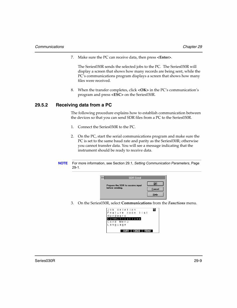
Communications Chapter 29
Series030R 29-9
7. Make sure the PC can receive data, then press <Enter>.
The Series030R sends the selected jobs to the PC. The Series030R will display a screen that shows how many records are being sent, while the PC’s communications program displays a screen that shows how many files were received.
8. When the transfer completes, click <OK> in the PC’s communication’s program and press <ESC> on the Series030R.
29.5.2 Receiving data from a PC
The following procedure explains how to establish communication between the devices so that you can send SDR files from a PC to the Series030R.
1. Connect the Series030R to the PC.
2. On the PC, start the serial communications program and make sure the PC is set to the same baud rate and parity as the Series030R; otherwise you cannot transfer data. You will see a message indicating that the instrument should be ready to receive data.
NOTE For more information, see Section 29.1, Setting Communication Parameters, Page 29-1.
3. On the Series030R, select Communications from the Functions menu.

Chapter 29 Communications
29-10 Series030R
4. Set the Data Format field to SDR.
5. Press the <RECV> softkey. The Series030R will display a message, WAITING FOR INPUT.
6. In the serial communications program on the PC, click <OK> or press <Enter>.
The PC will send the selected jobs to the Series030R. The Series030R will display a screen that shows how many records were received, while the communications program will indicate the file’s transfer progress.
7. When the transfer completes, click <OK> in the communications program and press <ESC> on the Series030R.
29.5.3 Assessing transmission problems
When transmitting data, the Series030R responds to both hardware and software flow control. The receiving computer may periodically use either or both of these techniques.
You may see either the Xon/Xoff Detected (software control) or CTS/RTS Detected (hardware control) messages appear on the Series030R's display.
If these messages do not disappear within a few seconds, the receiving computer may have stopped transmitting.
• Press <ESC> on the Series030R to resume transmission.
• To abort transmission and start over (perhaps at a lower baud rate), press <ESC> again.
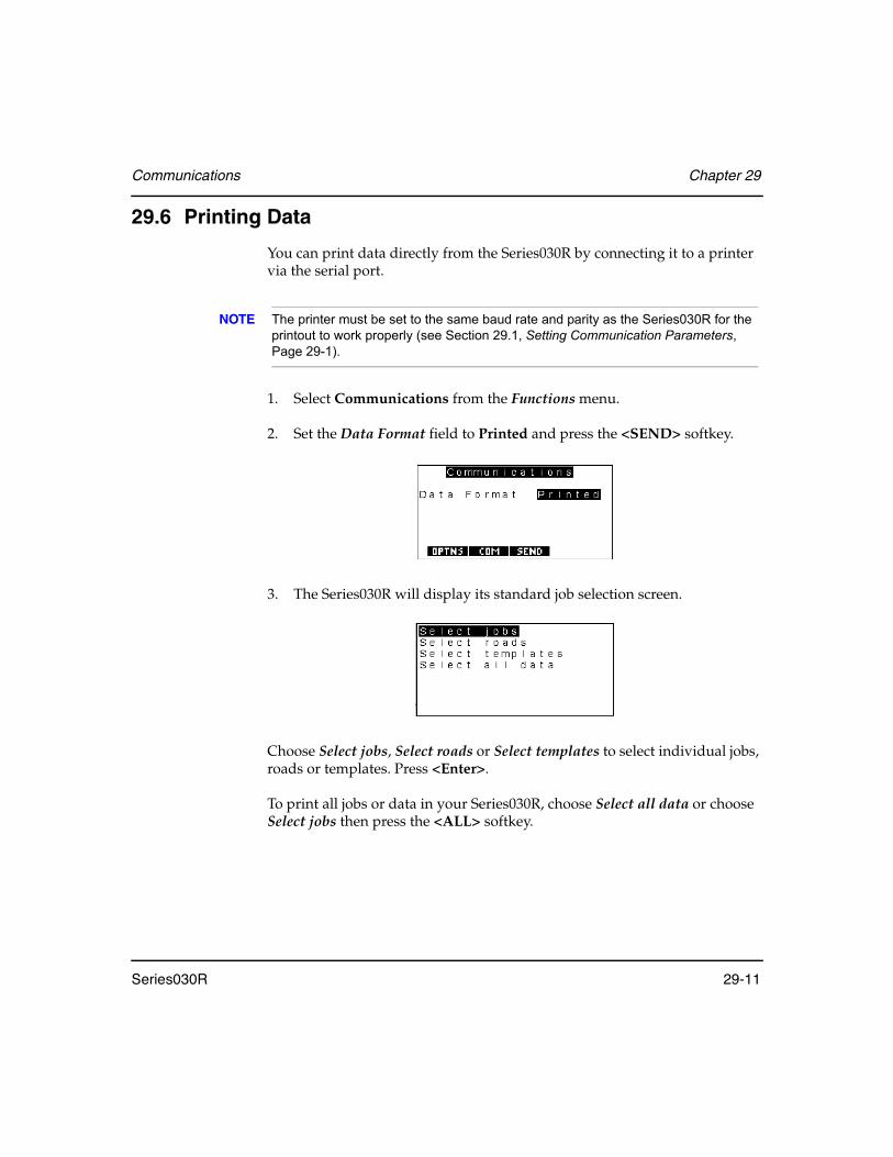
Communications Chapter 29
Series030R 29-11
29.6 Printing Data
You can print data directly from the Series030R by connecting it to a printer via the serial port.
NOTE The printer must be set to the same baud rate and parity as the Series030R for the printout to work properly (see Section 29.1, Setting Communication Parameters, Page 29-1).
1. Select Communications from the Functions menu.
2. Set the Data Format field to Printed and press the <SEND> softkey.
3. The Series030R will display its standard job selection screen.
Choose Select jobs, Select roads or Select templates to select individual jobs, roads or templates. Press <Enter>.
To print all jobs or data in your Series030R, choose Select all data or choose Select jobs then press the <ALL> softkey.
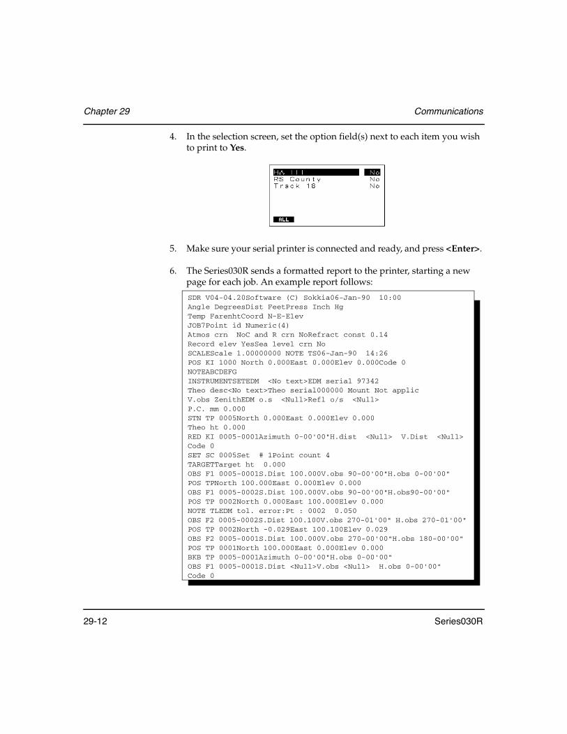
Chapter 29 Communications
29-12 Series030R
4. In the selection screen, set the option field(s) next to each item you wish to print to Yes.
5. Make sure your serial printer is connected and ready, and press <Enter>.
6. The Series030R sends a formatted report to the printer, starting a new page for each job. An example report follows:
SDR V04-04.20Software (C) Sokkia06-Jan-90 10:00Angle DegreesDist FeetPress Inch HgTemp FarenhtCoord N-E-ElevJOB7Point id Numeric(4)Atmos crn NoC and R crn NoRefract const 0.14Record elev YesSea level crn NoSCALEScale 1.00000000 NOTE TS06-Jan-90 14:26POS KI 1000 North 0.000East 0.000Elev 0.000Code 0NOTEABCDEFGINSTRUMENTSETEDM <No text>EDM serial 97342Theo desc<No text>Theo serial000000 Mount Not applicV.obs ZenithEDM o.s <Null>Refl o/s <Null>P.C. mm 0.000STN TP 0005North 0.000East 0.000Elev 0.000Theo ht 0.000RED KI 0005-0001Azimuth 0-00'00"H.dist <Null> V.Dist <Null>Code 0SET SC 0005Set # 1Point count 4TARGETTarget ht 0.000OBS F1 0005-0001S.Dist 100.000V.obs 90-00'00"H.obs 0-00'00"POS TPNorth 100.000East 0.000Elev 0.000OBS F1 0005-0002S.Dist 100.000V.obs 90-00'00"H.obs90-00'00"POS TP 0002North 0.000East 100.000Elev 0.000NOTE TLEDM tol. error:Pt : 0002 0.050OBS F2 0005-0002S.Dist 100.100V.obs 270-01'00" H.obs 270-01'00"POS TP 0002North -0.029East 100.100Elev 0.029OBS F2 0005-0001S.Dist 100.000V.obs 270-00'00"H.obs 180-00'00"POS TP 0001North 100.000East 0.000Elev 0.000BKB TP 0005-0001Azimuth 0-00'00"H.obs 0-00'00"OBS F1 0005-0001S.Dist <Null>V.obs <Null> H.obs 0-00'00"Code 0

Series030R 30-1
Chapter 30 SDR Database
The Series030R stores all observations, notes, and calculated results in an SDR database. This database is a list of records of different types, stored in chronological order. For example, each job's database starts with a JOB record that defines the job's name and continues with records stored in the order they were generated.
You have a complete record of your activities in the field. The only exception to chronological storage is the note record; you can insert a note record at any point in the database (see Section 3.3.4, Notes, Page 3-12).
It is not possible to alter data once it has been stored except for code fields and note records. Since these two entries are not used for calculations, you can edit them.
The Series030R has about 30 different record types that describe data such as station setup details, backsight orientation, target heights, observational measurements, and many others.
30.1 Searching During Calculation
Whenever the coordinates of a point are required, the Series030R performs an intelligent search of the database. This search is described in Chapter 7, Coordinate Search Logic. Take the time to read this short chapter; you will find the search rules have important and useful implications.
In this chapter
• Database conventions
• Database records
• Database messages

Chapter 30 SDR Database
30-2 Series030R
30.2 Understanding SDR Database Records
This section describes the use of records in the database and the fields within each record.
Each record has a derivation code, a two-character code describing how the record was generated and which part of the SDR software generated the record. The derivation code is sometimes blank. Special derivation codes descriptions are included in the following discussion of records.
APPLY SUPER
This record defines superelevation at a particular station on the road.
ATMOS
Atmospheric record. The two fields in this record define the temperature and pressure at the time of record generation. These values are used when atmospheric corrections are applied to observations. This record is generated after the station record only if you're applying atmospheric corrections.

SDR Database Chapter 30
Series030R 30-3
BKB
Back-bearing record. This defines the orientation correction for the current instrument setup. Fields list source point, target point, horizontal observation value from the instrument, and its corresponding azimuth. The orientation correction is the difference between the last two fields.
CIRCULAR VC
This record is part of a road's vertical alignment; it defines a circular vertical curve (arc).
COL
Collimation record. Fields define the vertical and horizontal angle correction required to compensate for collimation error in the current instrument.
DEFINE SUPER
This record specifies the limits of superelevation application.

Chapter 30 SDR Database
30-4 Series030R
HORZ ALIGN
This record marks the start of a road's horizontal alignment definition. The end station field is filled in automatically by the Series030R.
HORZ ARC
This record is part of a road's horizontal alignment; it defines an arc.
HORZ POINT
This record is part of the road's horizontal alignment and specifies the coordinates of a point the alignment passes through.
HORZ SPIRAL
This record is part of a road's horizontal alignment; it defines a portion of a spiral.

SDR Database Chapter 30
Series030R 30-5
HORZ STRAIGHT
This record is part of a road's horizontal alignment; it defines a straight section.
INSTR
Instrument record. The fields describe the type of instrument, and various instrument parameters. See Section 3.4.1.2, Selecting instrument type, page 3-14, for field descriptions.
JOB
Job record. This record type appears once at the start of a job. It defines the name of the job, the type of point name (4digit numeric or 14-character alphanumeric), and which corrections the Series030R should apply.
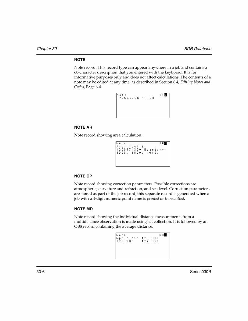
Chapter 30 SDR Database
30-6 Series030R
NOTE
Note record. This record type can appear anywhere in a job and contains a 60-character description that you entered with the keyboard. It is for informative purposes only and does not affect calculations. The contents of a note may be edited at any time, as described in Section 6.4, Editing Notes and Codes, Page 6-4.
NOTE AR
Note record showing area calculation.
NOTE CP
Note record showing correction parameters. Possible corrections are atmospheric, curvature and refraction, and sea level. Correction parameters are stored as part of the job record; this separate record is generated when a job with a 4-digit numeric point name is printed or transmitted.
NOTE MD
Note record showing the individual distance measurements from a multidistance observation is made using set collection. It is followed by an OBS record containing the average distance.

SDR Database Chapter 30
Series030R 30-7
NOTE NM
Notes manually entered by the user.
NOTE OS
Note record generated by an offset observation. It contains the raw observation details and offset direction. It is generated before the observation record that contains measurements adjusted for the offset.
NOTE RO
Note record generated in roading.
NOTE RS
Note record generated by the resection calculation.

Chapter 30 SDR Database
30-8 Series030R
NOTE SC
Note record generated by the set collection procedure.
NOTE SS
Note record generated when setting out road surface.
NOTE TL
Note record generated whenever a tolerance error message is displayed, and the error is accepted.
NOTE TP
Note record generated in topography.

SDR Database Chapter 30
Series030R 30-9
NOTE TS
Note record with a timestamp. It contains the date and time of the note creation.
NOTE TV
Note record generated by the traverse calculations. It lists information about how the calculation was performed.
OBS F1
Observation record measured on instrument face one. This record contains a source point name, target point name, horizontal observation, vertical observation, slope distance, and descriptive code. The vertical observation (zenith or horizontal) depends on the type specified in the most recent instrument record. This record appears in review as F1 but prints and transmits as an observation (OBS) record with an F1 derivation code.
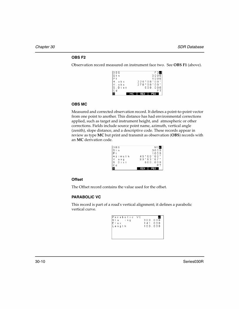
Chapter 30 SDR Database
30-10 Series030R
OBS F2
Observation record measured on instrument face two. See OBS F1 (above).
OBS MC
Measured and corrected observation record. It defines a point-to-point vector from one point to another. This distance has had environmental corrections applied, such as target and instrument height, and atmospheric or other corrections. Fields include source point name, azimuth, vertical angle (zenith), slope distance, and a descriptive code. These records appear in review as type MC but print and transmit as observation (OBS) records with an MC derivation code.
Offset
The Offset record contains the value used for the offset.
PARABOLIC VC
This record is part of a road's vertical alignment; it defines a parabolic vertical curve.

SDR Database Chapter 30
Series030R 30-11
POS
Position record. This record contains a point name, the point's coordinates, and a descriptive code.
RCHK
Road check. This record defines a point on a road by station and offset, not coordinates. It also contains fields showing the difference between the station and offset set out and the design point's station and offset.
RED
Reduced record. These fields define a point-to-point vector. Source point name, target point name, azimuth, horizontal distance, vertical distance, and a descriptive code are listed. An observation record in reduced (RED) view looks the same as a RED record.

Chapter 30 SDR Database
30-12 Series030R
ROAD NAME
This record marks the start of a road definition. It contains the name of the road.
RPOS
Road position. Like a position record, this record defines the position of a point but also includes the station and offset of the point relative to the current road definition.
RSTN
Road station. This record defines the position on which the instrument was set up (similar to a station record). In addition to the standard station fields, it lists the station and offset of the point relative to the current road definition.

SDR Database Chapter 30
Series030R 30-13
SCALE
Scale factor record. The field specifies a plane scale factor. Only one scale factor record is generated per job.
SET
Set of observations record. Fields indicate the start of a group of observations measured using the set collection procedure. The fields in the record define the station point name, set identification number (unique for the station), and a count of observations. Another field in this record is the word BAD, which you can use to indicate an inaccurate set of data.
STN
Station record. This contains a point name, point coordinates, height of the instrument set up on the point, and a descriptive code. A station record is entered in the database whenever you set up on a different point.
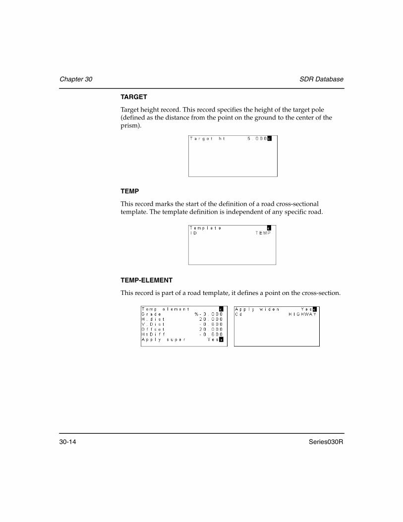
Chapter 30 SDR Database
30-14 Series030R
TARGET
Target height record. This record specifies the height of the target pole (defined as the distance from the point on the ground to the center of the prism).
TEMP
This record marks the start of the definition of a road cross-sectional template. The template definition is independent of any specific road.
TEMP-ELEMENT
This record is part of a road template, it defines a point on the cross-section.

SDR Database Chapter 30
Series030R 30-15
TEMP-SIDESLOPE
This record is part of a road template; it defines the grades for sideslopes at the edge of the road.
VERT ALIGN
This record marks the start of a road's vertical alignment definition.
VERT POINT
This record is part of a road's vertical alignment and specifies the station and elevation of a point that the alignment passes through.
XSEC
This record is part of a road definition; it defines which cross-sectional templates to use from a particular station along the road.
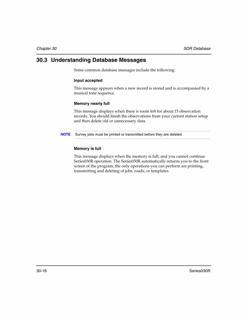
Chapter 30 SDR Database
30-16 Series030R
30.3 Understanding Database Messages
Some common database messages include the following:
Input accepted
This message appears when a new record is stored and is accompanied by a musical tone sequence.
Memory nearly full
This message displays when there is room left for about 15 observation records. You should finish the observations from your current station setup and then delete old or unnecessary data.
NOTE Survey jobs must be printed or transmitted before they are deleted.
Memory is full
This message displays when the memory is full, and you cannot continue Series030R operation. The Series030R automatically returns you to the front screen of the program; the only operations you can perform are printing, transmitting and deleting of jobs, roads, or templates.

Series030R 31-1
Chapter 31 Observational Calculations
This chapter presents the formulas and constants used by the Series030R for calculations. In addition to this information, it is also important to understand the principles described in Chapter 7, Coordinate Search Logic, because these principles can affect the outcome of coordinate calculations.
31.1 Correction Categories and Order of Application
The Series030R performs several corrections to readings as it converts them from the information on the instrument's screen to a POS record. These corrections can be grouped into two general categories:
• Instrument, environmental and job-related corrections• Geometric corrections
Instrument corrections include equipment configuration, Face1/Face2 observations, collimation and prism constant. Environmental corrections include pressure and temperature corrections. Job-related corrections include orientation, instrument height reduction, and target height reduction.
Geometric corrections include such things as curvature and refraction, slope reduction, sea level, and projection.
The Series030R always applies corrections in a specific sequence as it converts a raw observation to coordinates. The instrument, environmental, and job-related corrections are applied first, followed by the geometric corrections.
In this chapter
• Instrument, environmental, and job-related corrections
• Geometric reductions
• Miscellaneous calculations
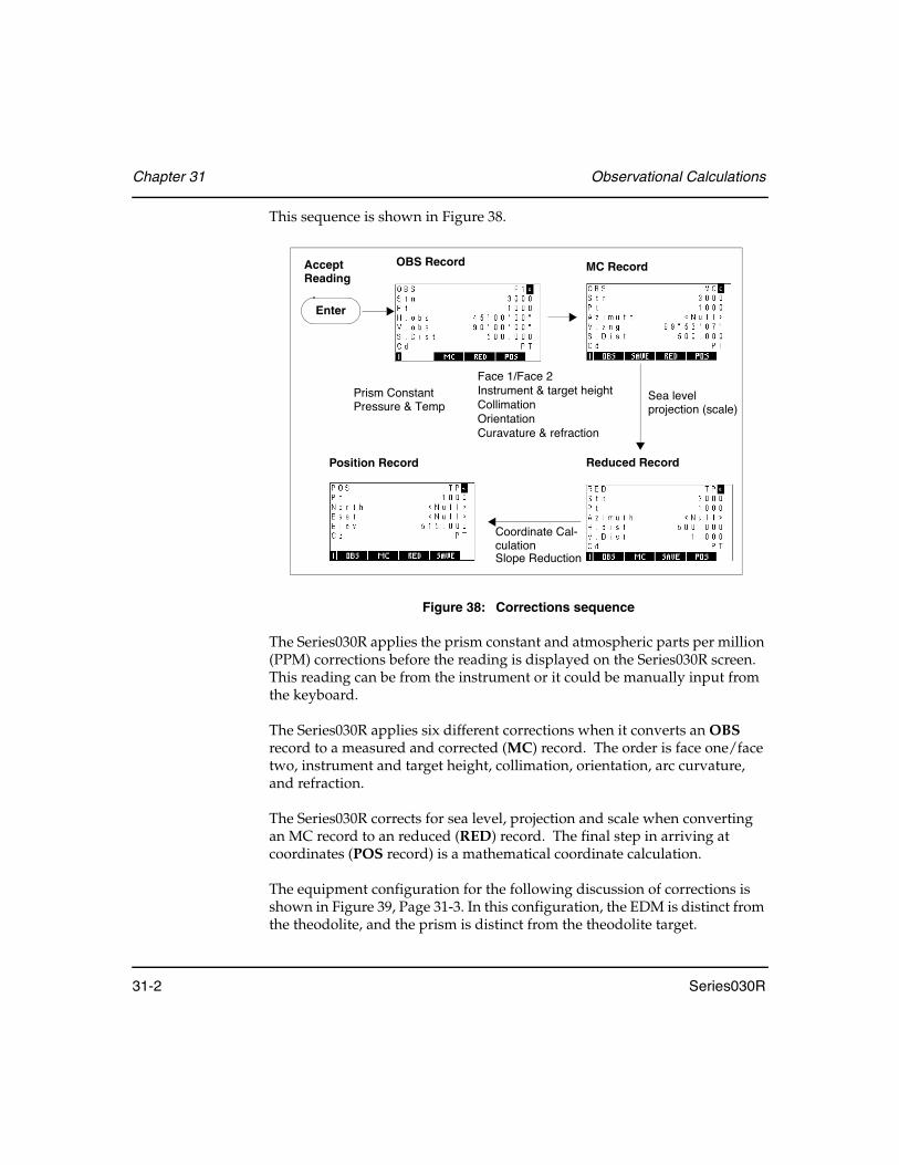
Chapter 31 Observational Calculations
31-2 Series030R
This sequence is shown in Figure 38.
Figure 38: Corrections sequence
The Series030R applies the prism constant and atmospheric parts per million (PPM) corrections before the reading is displayed on the Series030R screen. This reading can be from the instrument or it could be manually input from the keyboard.
The Series030R applies six different corrections when it converts an OBS record to a measured and corrected (MC) record. The order is face one/face two, instrument and target height, collimation, orientation, arc curvature, and refraction.
The Series030R corrects for sea level, projection and scale when converting an MC record to an reduced (RED) record. The final step in arriving at coordinates (POS record) is a mathematical coordinate calculation.
The equipment configuration for the following discussion of corrections is shown in Figure 39, Page 31-3. In this configuration, the EDM is distinct from the theodolite, and the prism is distinct from the theodolite target.
OBS Record MC Record
Reduced RecordPosition Record
Accept Reading
Enter
Prism ConstantPressure & Temp
Face 1/Face 2Instrument & target heightCollimationOrientationCuravature & refraction
Sea levelprojection (scale)
Coordinate Cal-culationSlope Reduction

Observational Calculations Chapter 31
Series030R 31-3
Figure 39: An instrument configuration
Using the Series030R with a simple prism on a pole, the EDM and theodolite are coincident; the prism and theodolite target are also coincident. In other words,
e1 Prism constant de EDM slope distance
e2 Theodolite height dt Theodolite slope distance
e3 EDM offset dc Slope distance, source to target point
e4 Theodolite target Z Theodolite vertical angle
e5 EDM reflector offset Zc Corrected vertical angle
e3 = 0
e5 = 0
de = dt
EDM
Prism
TheodoliteTarget
Target point
Theodolite
Source point

Chapter 31 Observational Calculations
31-4 Series030R
31.2 Instruments, Environmental and Job-Related Corrections
This category of corrections includes the following:
• Prism constant corrections• Pressure and temperature corrections• Face one/face two corrections• Instrument and target height reductions• Collimation corrections• Orientation corrections
31.2.1 Prism constant correction
This correction is applied to all slope distances:
NOTE Prism constants are usually negative.
31.2.2 Pressure and temperature correction
Pressure and temperature corrections are applied to all electronically measured distances if the Atmos crn field is Yes during job creation, and pressure and temperature values are entered. The correction applied is:
S1 = Measured slope distance
e1 = Prism constant
S2 = Resulting slope distance
S2 S1 e1+=
S2 = Slope distance
S3 = Corrected slope distance
J = Group refractive index for the EDM's carrier
N = Constant for the EDM's carrier
P = Atmospheric pressure in mmHg
T = Dry air temperature in °C
S3 S2 S2 J NP273.2 T+-----------------------– 10 6–×+=

Observational Calculations Chapter 31
Series030R 31-5
31.2.3 Face 1/Face 2 corrections
The vertical angle measurement (defined in the instrument record's V.obs field) is converted to an equivalent zenith angle. The derivation of the raw observation is determined as follows:
• If the vertical observation is in the range 0° to 180°, the derivation is F1 (face one). If it is in the range 180° to 360°, the derivation is F2 (face two).
• If the vertical angle observation is not present, the derivation is assumed to be F1.
• If the vertical observation falls outside the range 0° to 180°, it is converted to an equivalent angle within the range.
• If the derivation code is F2, it is assumed the telescope was reversed, so 180° is added to the horizontal observation for horizontal angle calcula-tions.
31.2.4 Instrument and target height reduction
Corrections for instrument and target heights are applied to uncorrected measurements of vertical angle and slope distance. In the next equations, these variables represent the following:
The vertical angle from the source point to the target point (Zc) is given by:
The slope distance from source point to target point (dc) is given by:
ez = Theodolite height
e4 = Theodolite target height
dt = Theodolite slope distance
Zcdt Zsin
dt Zcos e2 e4–+----------------------------------------tan 1–=
dcdt Zsin
Zcsin----------------=
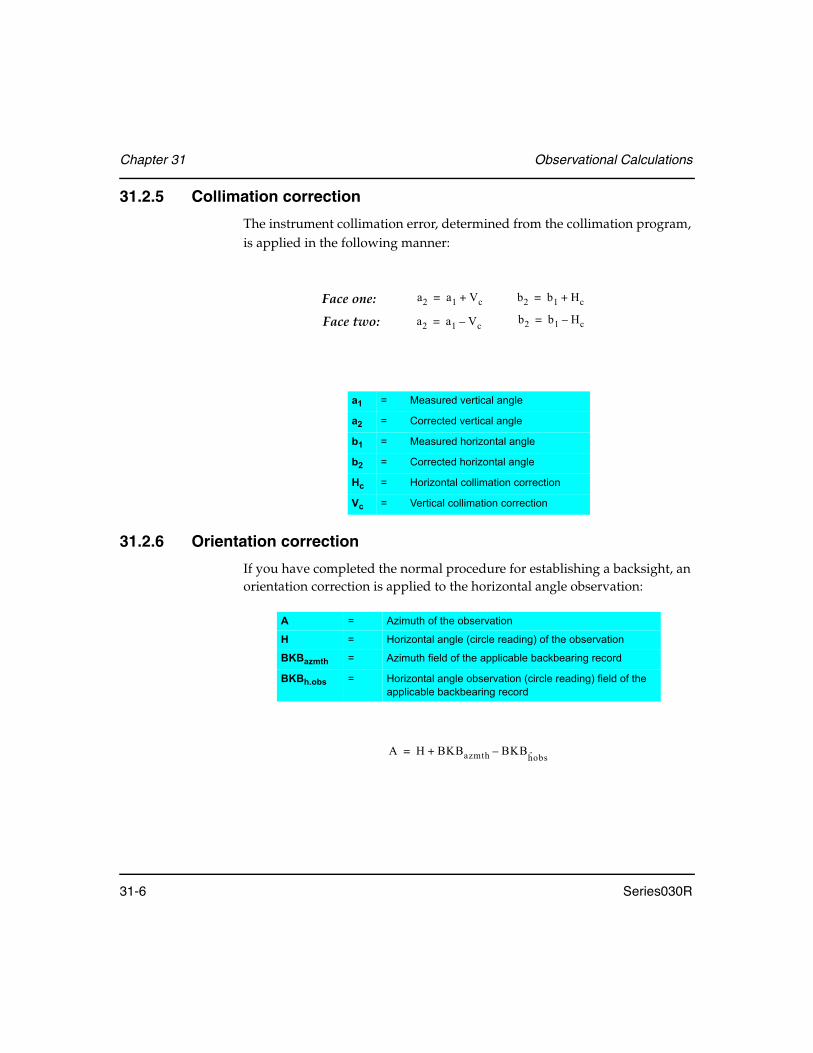
Chapter 31 Observational Calculations
31-6 Series030R
31.2.5 Collimation correction
The instrument collimation error, determined from the collimation program, is applied in the following manner:
31.2.6 Orientation correction
If you have completed the normal procedure for establishing a backsight, an orientation correction is applied to the horizontal angle observation:
a1 = Measured vertical angle
a2 = Corrected vertical angle
b1 = Measured horizontal angle
b2 = Corrected horizontal angle
Hc = Horizontal collimation correction
Vc = Vertical collimation correction
a2 a1 Vc+=
a2 a1 Vc–=
b2 b1 Hc+=
b2 b1 Hc–=
Face one:
Face two:
A = Azimuth of the observation
H = Horizontal angle (circle reading) of the observation
BKBazmth = Azimuth field of the applicable backbearing record
BKBh.obs = Horizontal angle observation (circle reading) field of the applicable backbearing record
A H BKBazmth BKBh··obs–+=

Observational Calculations Chapter 31
Series030R 31-7
31.3 Geometric Reductions
The following geometrical reductions and corrections may be applied to observations by the Series030R.
Figure 40: A reference figure for some of the reductions
Z = Zenith angle
v = Vertical distance
h = Elevation of source point
s = Slope distance
d1 = Horizontal distance at elevation of source point
d2 = Sea level chord
d3 = Spheroidal arc
d4 = Projected distance (not shown)
Target point
Earth’s surface
Source point

Chapter 31 Observational Calculations
31-8 Series030R
31.3.1 Curvature and refraction correction
The following correction is applied to vertical angles if the curvature and refraction correction field (C and R crn) is set to Yes during job creation.
31.3.2 Sea level correction
If the sea level correction field is Yes during job creation, the horizontal distance at the source point's elevation is reduced to the sea level chord (d2)
using the mean height of the vector:
Reduction of the sea level chord (d2) to the spheroidal arc (d3) involves a
correction of the following:
This correction exceeds 1mm only on distances greater than 9.9km. Consequently, the correction term is ignored and the spheroidal arc is taken to be the sea level chord:
k = Coefficient of terrestrial refraction (either 0.14 or 0.20 as selected when the job was created)
R = Approximate spheroid radius of 6,370,000 (meters)
S3 = Slope distance from Section 31.2.2, Pressure and temperature correction, Page 31-4
a2 = Vertical angle from Section 31.2.5, Collimation correction, Page 31-6
a3 = Corrected vertical angle (units=degrees)
a3 a21 k–( )S3
2R----------------------- 180
π---------×–=
d1 = Horizontal distance at the elevation of the source point
h1 = Elevation of the source point
ht = Elevation of the target point
R = Radius of the spheroid
R = Radius of the spheroid
d2 d1h1 ht+( )d1
2R---------------------------–=
d23
24R2-------------
d3 d2=

Observational Calculations Chapter 31
Series030R 31-9
31.3.3 Projection correction
The correction of the spheroidal arc (d3) to a projected distance (d4) depends on the projection used. Because the locally used projection is not known by the Series030R, a simple scale factor is used. The value of the scale factor is specified during job creation. For short and medium distance EDM work, this provides sufficient accuracy. The projection correction is as follows:
31.3.4 Slope reduction
Refer to Figure 40, to better understand this reduction. The horizontal and vertical components (d1 and v) of an observation are found from the vertical
angle (zenith distance) and slope distances by the following:
31.4 Other Formulas
The two formulas covered in this section include:
• Coordinate calculation• Inverse calculation
31.4.1 Coordinate calculation
Coordinate calculation is the last step in converting an OBS record to coordinates, a POS record. The coordinates of a target point are calculated from observed measurements and the coordinates of the source point:
sf = Scale factor in the current scale record
d4 d3 sf+=
d1 = Ssin(Z)
v1 = Scos(Z)
Z = Zenith angle
S = Slope distance
N2 N1 d4 A( )cos+=
E2 E1 d4 A( )sin+=
Z2 Z1 v4+=

Chapter 31 Observational Calculations
31-10 Series030R
The results are null if the source point coordinates are unknown.
31.4.2 Inverse calculation
The distances and angles associated with a line between two points are calculated from the coordinates of those points as follows:
N1, E1 & Z1 = coordinates of the source point
N2, E2 & Z2 = coordinates of the target
d4 = projected distance between the two points
A = azimuth
v2 = vertical distance
N1, E1 & Z1 = coordinates of the source point
N2, E2 & Z2 = coordinates of the target point
v = vertical distance from source to target point
A = azimuth of the line
a = zenith angle of the line
h = elevation of the source point
S = slope distance at the height of the station with slope reduction, sea level correction, and projection correction applied in reverse
R = radius of the spheroid
sf = scale factor
v Z2 Z1–=a 1– h
v---tan= A tan 1– E2 E1–
N2 N1–-------------------=
h N2 N1–( )2 E2 E1–( )2+=
h2 v2+( )R( ) RZ1 Z+
2-----------------–
⁄
sf-----------------------------------------------------------------=

Series030R A-1
Appendix A System Messages
<10Kb recvr memory
Less than 10 kilobytes of memory remain for a GPS survey.
Already a polygon
Points cannot be appended to a traverse list that already specifies a polygon.
Already exists
The azimuth, azimuth and distance, or observation keyed in already exists.
Ansermet < 2 No Redundancy caution
The least squares ansermet is less than two in positioning program. For more information, see Section 14.2.5, Understanding professional positioning results, Page 14-18.
Area too large
The area you attempted to subdivide is larger than the original polygon.
Backup lithium dead
The backup battery is discharged. All data may be lost if the main battery is removed.
Bad record order
An invalid SDR file has been detected during comms input.
BATTERY IS DEAD!
The main battery is discharged.

Appendix A System Messages
A-2 Series030R
Battery is low
The main battery is low.
BS azimuth not found
An azimuth to the backsight point cannot be found. Key in the azimuth or coordinates for the backsight.
BS bearing not found
A bearing to the backsight point cannot be found. Key in the bearing or coordinates for the backsight.
BS must be included
You must include the backsight point when entering the list of points for set collection.
BS not required
The backsight point does not need to be entered during set collection by direction.
Cancel input
You canceled comms input.
Cancel output
You canceled comms output.
Checksum error
A checksum error occurred during comms input, reading from an instrument, or loading a language file.
Code fields too long
The code fields may not total more than 16 characters, including a space between each field.
System Messages Appendix A
Series030R A-3
Code too long
The selected feature code will not fit into the remaining space.
Communications error
A general communications error has occurred. Examine your cabling, connections, and switches. Also check that the baud rates and parities are consistent between the Series030R and the other instrument or computer.
Computation of position not successful
Add more target points in positioning program. Too few target points were included from which to compute the unknown station position. Additional, non-identical target points should be added.
CTS/DSR detected
Comms output has paused. The CTS and/or DSR line is not enabled.
Curve overlap
The vertical curve overlaps with the previous one.
Delete all jobs before upgrading
You must output and delete all jobs in the Series030R's memory before upgrading the Series030R's software.
Diverging azimuths
An intersection was attempted but failed because the azimuths did not converge.
DS_BranchInRoute
A branch is in the Level Loop
DS_DistTolError
The distance entered is out of tolerance with the wire readings and stadia constant

Appendix A System Messages
A-4 Series030R
DS_ElevTol
An elevation tolerance error is located in the Level Loop.
DS_InvRodSiting
The rod is unable to be read by the NA2000. This situation could occur because not enough of the rod is in the sights or that the rod is inverted when the Series030R is expecting it to be non inverted.
DS_NullDist
A distance for the reading has not been entered.
DS_NullLowReading
The Low Wire of a three wire reading was not entered.
DS_NullMidReading
The Mid Wire of a three wire reading was not entered.
DS_NullReading
A reading has null values.
DS_NullTopReading
The Top Wire of a three wire reading was not entered.
DS_WireTolError
A wire reading entered is out of tolerance.
Duplicate crns
Corrections are set in both the Series030R and the instrument.
Duplicate point
An attempt was made to enter the same point twice in the list of preentered points for set collection.

System Messages Appendix A
Series030R A-5
EDM error
The instrument failed to take a distance reading.
EDM tol. error
The distance is not within the specified tolerance.
Elev not enabled
A GPS survey requires a job with Record Elev set to Yes when it was created.
Empty list
An attempt was made to set out a road or review a template, but the job contains no roads or templates.
Error receiving
An error occurred during comms input.
FC creation failed
Creation of a file for feature coding failed. This message may imply that memory is nearly full.
H.obs tol. error
The horizontal angle is not within the specified tolerance.
Illegal Shape
The specified polygon in area calculation has crossing vertices.
Incompatible UnitsWhen the Series030R is connected to a surveying instrument, it reports an error if the instrument's units (angle, distance, pressure, temperature and so on) are incompatible with the Series030R's.
Input interrupted
Loading of a language file was interrupted.

Appendix A System Messages
A-6 Series030R
Input not allowed
Input is not allowed in this field.
Instr read aborted
You canceled an instrument reading.
Internal math error
An internal math error occurred.
Invalid input
The data in the field is invalid.
Invalid OBS in set
A comms input set contains a POS, RED, or MC instead of an OBS.
Invalid set
A comms input set has an invalid structure.
Invalid:same as stn
The point must be the same as the current station.
Invalid:same coords
Two points can not have the same coordinates in a polygon (Areas program). An illegal shape results.
Invalid:same points
The source and destination points must be different.
Job limit exceeded
The maximum number of jobs already exists.
Limitation of target points exceeded
The maximum number of target points has been exceeded. Computation of unknown station position will still be computed if possible.
System Messages Appendix A
Series030R A-7
Linear
The three points selected to define a plane in Building face survey are colinear, and do not uniquely define a plane.
Low receiver battery
The GPS receiver battery is low.
Maximum iterations reached
The predefined maximum number of steps for the balancing computation has been reached. The resulting balancing factors were introduced to the BLAVE adjustment computation.
Mem nearly full
This message appears when the remaining space will allow less than 15 observations.
Memory is full
The RAM disk is full. You should output and then delete unnecessary jobs to create more memory space.
Mils Not Allowed
Two-Way Sets do not support mils as an angle unit.
Missing BS obs
In the occupied stations list in traverse, no backsight observation from the new station to the previous station exists.
Missing dist/ang to (point)
The traverse has degenerated due to lack of a distance or horizontal angle from one station to the next.
Missing FS Obs
In the occupied stations list in traverse, no observation to this point from the previous station exists.
Appendix A System Messages
A-8 Series030R
Modem Error
An unidentified modem error occured.
Modem Trans Cancel
You canceled a modem transmission.
Must be on boundary
On a fixedpoint subdivision, the fixed point MUST be on a vertex of the polygon.
Name already exists
The job name entered already exists.
Need 1 foresight
You must include at least one foresight point in the list of points for set collection.
Need 2 resection obs
Resection needs at least two observations.
No current job
The comms input has no job record, and a job is not open to which to add it.
No Elev in this Job
The Remote elevation program requires a job with Record Elev set to Yes when it was created.
No fixed close coords
The traverse was unable to close on any fixed coordinates.
No instr response
The instrument is not responding.

System Messages Appendix A
Series030R A-9
No more obs to point in setNo more observations were made to the point in the current set (from the current station).
No more points in set
No more points were observed in the current set (from the current station).
No more points to review
No more points were observed in sets from the current station.
No more sets to review
No more sets were recorded for the current station.
No sets exist for station
No sets were recorded for the given station.
No solution
The requested intersection calculation has no solution.
North/East is null
The Northing or Easting field of the given coordinate is null.
Not connected
The comms port could not be opened, no connection was made.
Not on traverse
Not enough information exists at two independent stations to form a traverse route.
Null elevation
A point was selected to define a building face plane that does not have an elevation (the elevation is <Null>).

Appendix A System Messages
A-10 Series030R
Null position
A point was selected to define a building face plane that does not have a northing or easting value (the northing or easting is <Null>).
Null not allowed
A value must be entered in this field.
Null position
An attempt was made to set out a point with a null Northing or Easting, or a POS record could not be stored because it was null.
Observations not balanced
The balancing procedure was not possible. A Least Absolute Value Estimation (LAVE) was executed instead of the BLAVE.
Offset too small
You cannot define templates that fold back.
P.C. too large
The prism constant is out of the range -99 to 99 mm.
Parallel Azimuths
An intersection failed because the specified azimuths were parallel.
Point exists
Coordinates for the point already exist.
Poor position
The GPS record just stored in the database does not have good values because of high PDOP.
Print or send first
Before a job can be deleted from the Series030R's memory, it must be printed or output via the comms connection.

System Messages Appendix A
Series030R A-11
Pt already on route
The station is already on the traverse list and is not the first station.
Pt id not numeric 4
GPS jobs MUST have 4-digit point IDs (alphanumeric IDs are not yet supported for GPS surveys).
PTS-10 in angle mode
The Pentax PTS-10 instrument must be set manually in EDM mode before a reading may be taken.
RAM disk error
An error occurred while writing to or reading from the RAM disk.
Receiver memory full
The memory in the GPS receiver is full.
Receiver not ready
The GPS receiver is not ready.
Receiver mode error
The GPS receiver is not in the expected mode.
Restart survey
You need to restart the GPS survey.
Results may suffer from rounding errors
Adjust target point constellation. Rounding errors occurred within the Linear Programming algorithms. Numerical results may not be sufficient.
Road empty
The road selected for setting out, road topo or road set out surface has no horizontal alignment defined.
Appendix A System Messages
A-12 Series030R
Search failed
The point does not exist.
SET is in a menu
The two-way SET is not responding, probably because it is in a menu. Press <I/O Clear> on the set keyboard to put an older instrument in Basic mode or a newer instrument in Select operation.
Station North/East is null
The Northing or Easting (or both) of the given station is (are) null.
Station Not Found
In the list of occupied stations in traverse, the station does not exist in the database.
Station too small
A larger station value must be entered.
Super overlap
The superelevation that you are trying to define overlaps with an existing superelevation definition.
There are no entries
You cannot delete, print out or output jobs when none exist.
Tilt error
A reading failed because the SET reported a tilt error.
Timeout
A timeout occurred during communications. Check your cable connections and switches. If timeout occurred after successful initiation of communications, make sure the connected device is handling flow control correct. Using a lower baud rate may solve the problem.

System Messages Appendix A
Series030R A-13
Too few points
At least three points must be specified before the polygon area will be calculated.
Too large
The value entered is too large for its intended use.
Too many files
Too many files have been created in a directory.
Too many points
An attempt was made to enter too many points into the list of preentered points in set collection.
Too many sets
More than 50 sets were recorded from the current station. Some of these (the most recent ones) will NOT be used to produce averaged MC records.
Too many sets to review
A maximum of 50 sets may be reviewed for a given station at any moment in time.
Traverse is full
The traverse occupied stations list has exceeded 250 stations.
Too small
The value entered is too small for its intended use.
Unable to determine a unique position
Adjust target point constellation. A unique position is not possible due to lack of observation data to target points in existing constellation. Full observations should be taken if possible, or additional target points should be added.

Appendix A System Messages
A-14 Series030R
Unable to determine approximate values
Adjust target point constellation. The existing target point constellation possess unstable geometry or contains an incomplete combination of bearings and/or distances which may give erroneous results. The target point constellation should be supplemented with additional observations.
Unable to execute
Insufficient space to execute program.
Undef Station
The station specified for setting out is outside the horizontal alignment.
Unequal scales
The scale factor of the road definition and the current job are not the same.
Unknown Point
The specified point was not found (its coordinates were not specified in the current job).
Unknown template
A template used in the road definition selected for setting out is not known.
V.obs tol. error
The vertical angle is not within the specified tolerance.
Wrong face
The Series030R expected an observation on one face (from a total station), but the observation was made on the other face.
Xoff detected
Comms output has paused because an Xoff character was received.
Zero not allowed
Zero is not a valid value for this field.
Series030R B-1
Index
Aadding
feature code list 8-3feature codes 8-7horizontal elements 28-16points to the set out list 18-2
addresses, configure for email 4-23alphanumeric code 8-1angle 3-11, 9-4, 13-4, 14-4, 16-1, 19-2, 28-53
eccentric station 14-5horizontal observation tolerance 4-14measuring 10-3, 10-5offset 10-3units 4-15vertical observation tolerance 4-14
arcangle 20-2back tangent 20-3calculator 20-1center point 20-3chord length 20-3defining 20-2, 25-2defining points to set out 20-3elevation 20-3horizontal arc in alignment roads 28-18intersection point 20-3length 20-3maximum chord-to-arc separation 20-4parallel offset 20-4perpendicular distance to 25-1point projection 25-1radial distance to 25-1radius 20-2setting out 20-1tangent length 20-3
areacalculating 22-1illegal shape 22-8subdividing 22-1
by rotating from a fixed point 22-4with a line parallel to an existing line
22-6atmospheric correction 5-3, 6-5atmospheric record 30-2attributes 8-1
alpha 8-11AutoCAD 8-1defining 8-11editing 8-11entering 8-12numeric 8-11
Index
B-2 Series030R
azimuth 9-4 to 9-5, 10-10, 12-3, 18-4, 19-2, 25-3, 26-6, 28-15
entering known 17-2entering known azimuths with distance
17-3
Bback-bearing record 9-3 to 9-4, 30-3backlight 4-19backsight 11-1, 17-4
averaging multiple backsights 9-4avoiding 9-4azimuth 12-3coordinates 9-3observations 9-2setup 9-1using to derive station elevation 9-6views
MC 9-3OBS 9-3POS 9-3RED 9-3
baseline 19-2, 24-2, 25-1defining 19-2, 25-2measuring from 24-1setting out points 24-2
battery 2-4, 4-18BIOS 4-19building face survey 13-1
surveying a vertical plane 13-4surveying nonvertical planes 13-5
Ccalculations
area 22-1atmospheric correction 5-3, 6-5 to 6-6, 30-
6, 31-4collimation correction 6-6, 11-24, 15-1, 31-
6coordinate calculation 31-9curvature and refraction correction 5-3, 6-
6, 30-6, 31-8environmental corrections 31-1face 1/face 2 corrections 31-5geometric corrections 31-1geometric reductions 31-7in two-dimensional space 5-3instrument and target height reduction 31-
5instrument corrections 31-1instrument, target height reduction 6-6intersection 23-1inverse calculation 31-10job-related corrections 31-1least squares 26-3orientation correction 6-6, 9-4, 31-6pressure and temperature correction 31-4prism constant correction 6-6, 31-4projection correction 31-9reciprocal calculation 11-3reciprocal vertical 4-8, 4-12resection 14-4roading 28-37
cross-section calculation 28-39pivot calculation 28-39superelevation calculation 28-37template calculation 28-38widening calculation 28-37
sea level correction 5-4, 30-6, 31-8slope reduction 31-9traverse 12-1, 12-4, 30-9traverse adjustment
angular 12-8
Index
Series030R B-3
coordinate-compass rule 12-7coordinate-transit rule 12-7
using backsight coordinates 9-4card
deleting files 4-40formatting 4-35managing 4-35transferring data from a Series030R 4-36transferring data to Series030R 4-38viewing statistics 4-39
catch point 28-34, 28-49, 28-56, 28-58CF card 2-5code fields 4-8, 4-11, 10-2, 28-49
modifying 6-4COGO menu 4-1 to 4-2, 4-44, 17-1, 18-1, 19-2, 20-2, 21-1, 22-1, 23-1, 23-3, 24-1, 26-2 to26-3cold boot 2-4collimation error measurement 15-1communications 4-21, 6-8, 29-1
hardware 29-1parameters 29-2printing 29-11setting Series030R parameters 29-2transferring SDR files 29-7
configure reading 4-6control job 5-6control points 28-48converting 29-7coordinates 6-8 to 7-1, 9-4
backsight 9-3calculating 7-1, 31-9defining for building face survey 13-3determining with resection 14-3entering known 17-2establishing from taped measurements 24-
3order of 4-16search rules 7-1, 7-3searching for 6-3, 30-1station elevation 9-6station setup 9-1transformations 26-1
Helmert 26-1linear 26-1
creatingfeature code list 8-3jobs 5-1roads 28-7templates 28-29
cross-sectionroad template 28-29setting out 28-50survey 27-1
centerline 27-7direction 27-3offset 27-8
CSV file formatting 29-6
Ddatabase
see survey data

Index
B-4 Series030R
data collection 4-43data entry 3-7
alphanumeric fields 3-9angles 3-11feature codes within notes 3-13menus 4-1notes 3-12numeric fields 3-9option fields 3-10point numbers and names 3-11
date format 4-16decimal places 8-11deleting
feature code list 8-4feature codes 8-9horizontal elements from alignment roads
28-16jobs 4-18, 5-8points from the set out list 18-3roads 28-11superelevation from alignment roads 28-
28templates 28-11widening from alignment roads 28-28
dial-upconfigure 4-21configure addresses 4-23configure ftp 4-25configure ISP 4-24exit 4-34functions menu 4-2receive email 4-30send email from Series030R 4-27send email to Series030R 4-29start 4-22
dial-up errors, messages 4-32direction 10-6
Eediting
see modifying
EDM, fixed tolerance 4-14elevation 5-3, 16-1, 19-4, 23-3, 28-25, 28-49
adjusting to new coordinate system 26-1calculating 9-6interpolated 25-1linearly interpolated 20-1remote 16-1using backsight 9-6
emailabout configuration 4-21configure ISP 4-24dial-up menu 4-2exit dial-up 4-34receive 4-30send from Series030R 4-27send to Series030R 4-29set up addresses 4-23start dial-up 4-22
FF1/F2 4-7feature code list 8-1, 8-9
adding 8-3deleting 8-4managing 8-2renaming 8-5reviewing statistics 8-6selecting 8-3sorting 8-4
feature codes 3-13, 8-1, 10-2adding 8-7attributes 8-11code list active 4-8deleting 8-9managing 8-6modifying 8-8 to 8-9notes, using with 3-13sorting 8-4using 8-9

Index
Series030R B-5
fieldsAction 10-11alpha numeric 3-9code fields 4-8, 4-11Info 8-11numeric 3-9option 3-10viewing all in record 6-4
filesconverting 29-7transferring 29-7
ftpconfigure connections 4-25
Functions menu 4-1 to 4-3, 6-8, 8-1 to 8-2, 8-9, 29-2functions menu 29-1
Hhardware 2-1, 4-18
communications 29-1precautions 2-2settings 4-18
height, prism to point 16-2Helmert transformation 26-2
average deviation error 26-3points transferred into different job 26-1
horizontal observation tolerance 4-14horizontal offset 28-49
Iinfo blocks 4-8, 4-10initializing 2-3instrument types 1-2intersection 23-1
azimuth and distance calculations 23-1point 25-1, 25-4set out point 23-3two azimuths calculations 23-1two distances calculations 23-1
inverse 21-1ISP configurations 4-24iteration 14-3
Jjob 5-1
accessing statistics 5-5control job 5-6creating 5-1deleting 4-18, 5-8opening 5-4renaming 5-6settings 5-9transforming coordinate system 26-3verifying the current job 5-7
Kkeyboard 3-4
accessing softkeys 3-6inputting data 17-1operating keys 3-5
View 6-1, 7-4

Index
B-6 Series030R
Llanguage 4-42least squares adjustment 4-13, 14-3least squares calculation 26-3least squares reduction 14-1line
checking alignment 19-1defining the baseline 19-2drawing from points 8-7drawing in output 8-1length increments 19-3offset 19-3parallel to baseline 19-3perpendicular distance to 25-1point projection 25-1segments 19-3setting out 19-1setting out points relative to 19-6subdividing area 22-1
linear transformation 26-3rotation 26-5translation 26-4
MMC 6-6, 7-1, 31-2MEAS mode 2-3, 3-1, 4-8memory 4-19, 5-8, 5-10, 6-8, 28-11memory card 2-5menus 1-3, 4-1
accessing options 4-2COGO 4-1 to 4-2, 4-44, 17-1, 18-1, 19-2,
20-2, 21-1, 22-1, 23-1, 24-1, 26-2to 26-3
exiting options 4-2Functions 4-1 to 4-3, 6-8, 8-1 to 8-2, 8-9,
29-2Road 4-1 to 4-2, 4-45Survey 4-1 to 4-2, 4-43, 11-1, 13-1, 14-1,
16-1, 17-1messages
see system messages
modifyingattributes 8-11backsight view 9-3codes 6-4communication parameters 29-1feature codes 8-8job settings 5-9notes 6-4point in set out list 18-1stored data exceptions 30-1
Nnotes 3-12, 5-4, 5-7, 6-1, 6-4, 22-4, 24-3, 25-3, 28-8, 28-52, 28-54, 28-56
building face 13-4correction parameters 30-6entering 3-12feature codes within 3-13, 8-9info blocks 4-8modifying 6-4offset observation 30-7reciprocal calculations 11-6resection 30-7roading 30-7set collection 30-8time stamp 30-9tolerance error message 30-8topography 30-8traverse 30-9user-defined 30-6 to 30-7
Index
Series030R B-7
OOBS 7-1observations
angles-only reading 10-2attribute entry 8-12averaging multiple observations 10-10backsight 9-2building face 13-1collecting sets 11-1entering known 17-4face order 11-2horizontal 9-5
conversions 9-5initiating 10-1offset 10-3offset measurements 10-2offset types
angle 10-3single-distance 10-3single-distance offset 10-5two-distance offset 10-3, 10-8
order of 11-2preentering points 11-3, 11-6records 10-6reviewing 6-5sets 11-6 to 11-7
Good/Bad 11-23return sights 11-22reviewing 11-9
storing 10-2tolerances 4-13topography 10-1views 4-7, 6-7 to 7-1
MC 29-5measured and corrected (MC) 6-6OBS 9-3, 29-5output formats 29-5POS 29-5position (POS) 6-6, 17-6RED 29-5reduced (RED) 6-6
save 6-7weighting of 4-13
off-line station 14-5offset 28-49, 28-58
cross-section survey 27-7measurements 10-2observations
angle 10-3single distance 10-3single-distance offset 10-5two-distance offset 10-3, 10-8
record 30-10opening
job 5-4records for viewing 6-4
Pparameters
communication 29-2system 4-19
Index
B-8 Series030R
plotted output, drawing linework 8-1point
adding to the set out list 18-2arc set out 20-4calculating coordinates 7-1catch point 28-34, 28-49, 28-56, 28-58control points 28-48deleting from set out list 18-3duplicate 22-3intersection 25-1, 25-4known 18-2, 21-2names 3-11numbers 3-11observing 10-2perpendicular distance to arc 25-1perpendicular distance to line 25-1projections 25-1 to 25-2reference point 28-58relative to an established line 19-6renaming 10-12searching for coordinates 7-1set out list 18-2setting out 18-5specifying name length and type 5-2target point 10-7transforming coordinate system 26-1
POS 6-6, 7-1, 31-2position record 6-7pressure 4-15, 9-2printing 29-11prism 10-7, 16-1
constant 6-5entering direction 10-6entering the distance 10-5
RREC mode 2-5receive email 4-30reciprocal vertical calculations 4-8, 4-12records 6-3, 30-2
chronological storage 30-1converting OBS to POS 31-9derivation code 30-2navigating 6-2observation 4-7opening for viewing 6-4transmitting 6-8type 30-2
APPLY SUPER 28-37, 30-2ATMOS 30-2back-bearing 10-14BKB 9-3, 30-3CIRCULAR VC 30-3COL 15-4, 30-3DEFINE SUPER 28-37, 30-3HORZ ALIGN 30-4HORZ ARC 30-4HORZ POINT 30-4HORZ SPIRAL 30-4HORZ STRAIGHT 30-5INSTR 30-5JOB 30-1, 30-5NOTE 6-1, 10-12, 30-6NOTE AR 30-6NOTE CP 30-6NOTE JS 5-9NOTE MD 30-6NOTE NM 30-7NOTE OS 10-6, 30-7NOTE RO 30-7NOTE RS 30-7NOTE SC 30-8NOTE TL 30-8NOTE TP 30-8NOTE TS 30-9NOTE TV 30-9

Index
Series030R B-9
OBS 6-5, 31-9OBS F1 30-9OBS F2 30-10OBS MC 30-10Offset 30-10PARABOLIC VC 30-10POS 7-1, 7-4, 16-2, 22-1, 22-5, 28-15,
28-23 to 28-24, 30-11, 31-9RCHK 28-61, 30-11RED 17-2, 21-2, 30-11ROAD NAME 30-12RPOS 28-3, 28-13, 28-52, 28-54, 28-56,
28-60, 28-62, 30-12RSTN 28-45, 30-12SCALE 30-13SET 30-13STN 7-1, 30-13TARGET 30-14TEMP 30-14TEMP-ELEMENT 30-14TEMP-SIDESLOPE 30-15VERT ALIGN 30-15VERT POINT 30-15XSEC 28-39, 30-15
views 6-7RED 6-6, 7-1, 31-2refraction constant 5-4removing
see deletingrenaming
feature code list 8-5job 5-6points 10-12roads 28-9
reportsprinting 29-12staking notes 28-57
resection 4-13, 14-1, 30-7calculating 14-3eccentric station setup 14-5iteration 14-3performing 14-2reviewing sets 14-4
reticle 4-19reviewing
collected sets 11-9coordinates 6-3observations 6-5survey data 6-2traverse data 12-5
Road menu 4-1 to 4-2, 4-45roading 28-1, 30-7
alignment roads 28-3applying superelevation 28-25applying widening 28-25defining 28-4, 28-13deleting superelevation 28-28deleting widening 28-28horizontal 28-4, 28-14
adding horizontal elements 28-16deleting horizontal elements 28-16horizontal arc 28-18horizontal point 28-20horizontal spiral 28-19horizontal straight 28-17
reviewing 28-14setting out 28-4vertical 28-4, 28-21
circular vertical curves 28-24end point 28-25parabolic vertical curves 28-23start point 28-22straight grades 28-25
calculations 28-37cross-section 28-39pivot 28-39superelevation 28-37template 28-38
Index
B-10 Series030R
widening 28-37centerline 28-1cross-section 27-1, 28-2
adding 28-37defining 28-35replacing 28-37setting out 28-50
applying a vertical offset 28-53template 28-1
delete road 28-11example 28-40projection scale factor 28-8roads
accessing statistics 28-9creating 28-7renaming 28-9selecting 28-7selecting a road definition type 28-12setting out 28-46setting out road surface 28-62
cut/fill 28-62setting out sideslopes 28-54setting up road station 28-44staking notes 28-57storing results 28-57
string road 28-3superelevation 28-5template 28-5
defining 28-29point by distance and grade 28-32point by distance and vertical distance
28-34point by offset and height difference
28-31sideslope definition 28-34
transferring design to Series030R 28-2using road topography 28-61
roading, string roaddefining 28-13
roadsdeleting 28-11
RPOS 28-60
Sscale factor 5-2screen
backlight 4-19form 3-7
SDR files 29-7converting 29-1, 29-7output formats 29-4transferring 29-1, 29-7transferring out 29-7
SDR functionality 1-1, 2-3, 3-1send email from Series030R 4-27send email to Series030R 4-29Series030R
basic operations 3-1communications 4-21configuration 4-6entering data 3-7faces 15-2hardware 2-1, 4-18introduction 1-1keyboard 3-4menu structure 4-1operating
MEAS mode 3-1REC mode 3-3
operating modes 3-1operating temperatures 2-7precautions 2-2ruggedness 2-7SDR functionality 1-1servicing 2-7softkeys 3-6storage 2-7technical support 1-2turning on/off 2-3upgrading software 4-20
Index
Series030R B-11
servicing 2-7set out list
adding points 18-2deleting points 18-3sorting by azimuth 18-4
setscollimation correction 11-24GOOD/BAD 11-23observing 11-6 to 11-7return sights 11-22reviewing 11-9
ALL level 11-13POINTS level 11-14SETS level 11-11SETS-POINTS level 11-18SETS-POINTS-FACES level 11-21
reviewing for resection 14-4set collection 11-1
method 11-1tolerances 4-13
setting outarcs 20-1cross-section 28-50intersection point 25-4lines 19-1points 18-5road surface 28-62roads 28-46sideslopes 28-54
setting uproad station 28-44station 9-1

Index
B-12 Series030R
slope distance 9-6, 10-10, 14-4softkeys 3-6
% 19-3, 28-27, 28-331 19-3ADD 8-2, 8-6ADJUST 12-8ALL 11-12 to 11-13, 18-2, 18-4, 29-8, 29-11ANGLE 10-2, 15-3ARC 20-5, 25-2BAD 11-23CHORD 20-5CNFG 10-2COGO 4-44COM 29-2CPT 28-48CREATE 20-3CTRL 5-6DEL 4-42, 8-2, 8-6, 18-3DWN 28-33EDIT 6-5, 8-2, 8-7, 14-3FUNC 4-3HOR 28-33HORIZ 19-3HORIZONT 28-27INCR 28-48INS 8-7, 18-2INTERSEC 25-3LINE 19-4, 19-6, 25-2LISTS 4-37, 8-2 to 8-7MC 6-6, 17-6METHOD 28-18NEW 5-2, 28-8, 28-29NEXT 6-2, 28-48NO 15-4, 25-3OFS 10-2 to 10-3, 10-5, 10-8OFS-2D 10-3OFS-D 10-3, 10-5OPTIONS 4-37, 11-2, 12-6, 29-5OPTNS 6-8, 26-5, 28-58OSF-2D 10-8OTHER 23-2PGDN 6-2, 28-9
PGUP 6-2, 28-9POINTS 23-2POS 17-6PREV 6-2, 28-48PTS 11-13 to 11-14RANGE 18-3RCHK 28-61READ 3-6, 10-2, 13-2, 19-2, 19-8, 20-3, 25-
3REC 2-3, 3-1RECV 29-10RED 6-6, 17-6REVIEW 28-14, 28-16, 28-30RNDUP 20-5ROAD 4-45, 28-1RPOS 28-60RPT 28-57SAVE 6-7SD 11-19SEND 29-8, 29-11SET 4-20SETS 11-14SHFT 6-2S-O 23-3, 24-3, 25-4SRCH 6-2STA- 27-3, 28-48STA+ 27-3, 28-48STAT 5-5 to 5-6, 8-2, 28-10STATS 28-9STORE 12-5, 16-2, 18-8, 19-4 to 19-5, 19-
8, 20-5 to 20-6, 23-3, 24-3, 25-3 to 25-4, 28-64
SURV 4-43SYSTEM 4-19TARGET 19-8, 28-52 to 28-53, 28-56, 28-64UNDO 28-16UP 28-33V 11-19VERSION 4-20YES 9-4, 15-4

Index
Series030R B-13
staking notes 28-57standard deviation 4-13station
calculating elevation 9-6eccentric station setup 14-5setup 9-1
stationing 28-49statistics
feature code list 8-6job 5-5roads 28-9viewing card information 4-39
storingarea 22-4calculated results 30-1coordinates of arc points 20-3, 20-5coordinates of point to set out 19-4data 2-7intersected point 23-3intersection point 25-4notes 30-1observations 10-2, 30-1point observation results 18-6point projection 25-3position record 16-2, 22-5reduced (RED) record 21-2results for roads 28-57, 28-60RPOS records 28-64subdivision POS records 22-6traverse data 12-5
superelevation 30-3survey data 6-1, 30-1
chronological storage 30-1messages 30-16navigating through records 6-2opening a record 6-4reviewing 6-2searching 6-3searching during calculation 30-1understanding SDR database records 30-2
survey jobssee job
Survey menu 4-1 to 4-2, 4-43, 11-1, 13-1, 14-1, 16-1, 17-1system messages 3-14, A-1system parameters 4-19
Ttemperature 4-15, 9-2template
deleting 28-11road cross-section 28-29
theodolite height 9-2time format 4-16time out 4-17timestamp 4-17, 30-9tolerances 4-13, 30-8topography 10-1, 30-8
averaging multiple backsights 9-4tolerances 4-13
transferringobservation records 6-8SDR files 29-7sending partial job 29-5setting communication parameters 29-1specifying output format 29-4transmission problems 29-10
transmission problems 29-10transverse mercator projection 5-2traverse 12-1
adjusting 12-1, 12-5, 12-8angular adjustment 12-8coordinate adjustment 12-7
calculatingbacksight and foresight azimuths 12-3route 12-3starting point 12-2
reviewing 12-5storing 12-5

Uunits 4-14
angle 4-15coordinate order 4-16decimal usage 4-16distances 4-15grade 4-16pressure 4-15sideslope grade 4-16stationing 4-16temperature 4-15zero azimuth 4-16
upgrading software 4-20
Vvector 10-8, 21-2vertical observation tolerance 4-14views
see observations, views
Wwarm boot 2-3

SOKKIA CO. LTD. INTERNATIONAL DEPT. - 260-63, Hase, Atsugi-si, Kanagawa, 243-0036 Japan, Phone +81-46-248-0068 Fax +81-46-247-6866
SOKKIA CORPORATION. - 16900 W 118th Terrace, Olathe, Kansas, 66061 U.S.A., Phone +1-913-492-4900 Fax +1-913-492-0188 E-mail [email protected]
SOKKIA CORPORATION (CANADA). 1050 Stacey Court, Mississauga, Ontario, L4W 2X8 Canada, Phone 1-905-238-5810 Fax 1-905-238-9383
SOKKIA LATIN AMERICA CORPORATION. 2232 NW 82nd Avenue, Miami, FL33122, U.S.A., Phone +1-305-599-4701 Fax +1-305-599-4703E-mail [email protected]
SOKKIA PTY. LTD. Rydalmere Metro Centre, Unit 29, 38-46 South St., Rydalmere, NSW 2116 Australia Phone +61-2-9638-2400 Fax +61-2-9638-2200 E-mail [email protected]
SOKKIA KOREA CO. LTD. Sesin Building, 2Fl. Chungam Bldg, 129-11, Chungam-dong, Kangnam-ku, Seoul, Republic of Korea Phone +82-2-514-0491 Fax +82-2-514-0495 E-mail [email protected]
SOKKIA SINGAPORE PTE. LTD. 401 Commonwealth Drive, #06-01 Haw Par Technocentre, Singapore 149598 Phone +65-6479-3966 Fax +65-6479-4966 E-mail [email protected]
SOKKIA (M) SDN. BHD. Dataran Prima, No.31-3, Jalan PJU 1/42A, 47301 Petaling Jaya, Selangor Darul Ehsan, Malaysia Phone +60-3-78052197 Fax +60-3-78054069 E-mail [email protected]
SOKKIA INDIA PVT. LTD. C-25, 2nd Floor, Sector-8, Noida-201301, India Phone +91-120-2424154/159, +91-120-2424499/501 Fax +91-120-2424158 E-mail [email protected]
SOKKIA PAKISTAN (PVT.) LTD. Suite #A-2, 4th Floor, Westland Trade Centre, 4th Floor C-5, Central Commercial Area Block 7 & 8, K.C.H.S.U. Ltd. Shaheed-e-Millat Road, Karachi, Pakistan, Phone +92-21-4313151/3 Fax +92-21-4313154
SOKKIA GULF. P.O.Box 4801, Dubai, U.A.E., Phone +971-4-3368539 Fax +971-4-3368549 E-mail [email protected] RSA PTY. LTD. Sokkia House, Centuria Park Unit 10, 265 Von Willich Avenue, Centurion 0157, Pretoria (or P.O. Box 7998, Centurion, 0046) Republic
of South Africa, Phone +27-12-663-7999 Fax +27-12-663-7998 E-mail [email protected]
SOKKIA HEAD OFFICE - http://www.sokkia.co.jp/english/sokkia.htm
SOKKIA NORTH AMERICA - http://www.sokkia.com
SOKKIA MEXICO, CENTRAL AND SOUTH AMERICA - http://www.sokkia.com/worldwide.htm
SOKKIA AUSTRALIA/NEW ZEALAND - http://www.sokkia.com.au
SOKKIA KOREA - http://www.sokkia.co.kr/
SOKKIA SINGAPORE/AFRICA/MIDDLE EAST/INDIA - http://www.sokkia.com.sg/

SOKKIA (EUROPE) B.V., Dutch Market. Businesspark De Vaart, Damsluisweg 1, 1332 EA Almere, P.O. Box 1292, 1300 BG Almere, The Netherlands, Phone +31-36-53.22.880 Fax +31-36-53.26.241 E-mail [email protected]
SOKKIA LTD. Datum House, Electra Way, Crewe Business Park, Crewe, Cheshire, CW1 6ZT United Kingdom, Phone +44-1270-250.5.11 Fax +44-1270-25.05.33 E-mail [email protected]
SOKKIA S.R.O. Skroupovo námestí 1255/9, 130 00 Praha 3, Czech Republic, Phone +420-2-2272 6010 Fax +420-2-2272 6159 E-mail [email protected]
SOKKIA S.A. Rue Copernic, 38760 Chasse-sur-Rhóne, France, Phone +33-(0)4-72490303 Fax +33-(0)4-72492878 E-mail [email protected] N.V./S.A. Doornveld, Business Park, Asse 3, Nr.11-B1, 1731 Zellik (Brussels) Belgium, Phone +32-2-466.82.30 Fax +32-2-466.83.00
E-mail [email protected]
SOKKIA EUROPE/RUSSIA - http://www.sokkia.net/ (for UK, http://www.sokkia.co.uk)