service— 36026v5j, 36026v7j/v7w 42026v6j/v6w washer …
TRANSCRIPT

Published Manual Number/ECN: MAP36VXXCE/2006145A• Publishing System: TPAS• Access date: 4/6/2006• Document ECN's: Latest Available
Service—
36026V5J, 36026V7J/V7W42026V6J/V6WWasher-Extractors
PELLERIN MILNOR CORPORATION POST OFFICE BOX 400, KENNER, LOUISIANA 70063-0400, U.S.A.

Please ReadAbout the Manual Identifying Information on the CoverThe front cover displays pertinent identifying information for this manual. Most important, arethe published manual number (part number) /ECN (date code). Generally, when a replacementmanual is furnished, it will have the same published manual number, but the latest available ECN.This provides the user with the latest information applicable to his machine. Similarly alldocuments comprising the manual will be the latest available as of the date the manual wasprinted, even though older ECN dates for those documents may be listed in the table ofcontents.
When communicating with the Milnor factory regarding this manual, please also provide theother identifying information shown on the cover, including the publishing system, access date,and whether the document ECN’s are the latest available or exact.
References to Yellow Troubleshooting PagesThis manual may contain references to “yellow pages.” Although the pages containingtroubleshooting procedures are no longer printed on yellow paper, troubleshooting instructions, ifany, will be contained in the easily located “Troubleshooting” chapter or section. See the table ofcontents.
Trademarks of Pellerin Milnor CorporationThe following, some of which may be used in this manual, are trademarks of Pellerin MilnorCorporation:
Ampsaver® Dye-Extractor® Gear Guardian® Milnet® Staph-Guard®
Autolint® Dyextractor® Hands-Off® Milnor® System 4®
Auto-Purge® E-P Express® Hydro-Cushion® Miltrac System 7®
Autovac E-P OneTouch® Mildata® Miltron Totaltrol®
CBW® E-P Plus®
Comments and SuggestionsHelp us to improve this manual by sending your comments to:
Pellerin Milnor CorporationAttn: Technical PublicationsP. O. Box 400Kenner, LA 70063-0400
Fax: (504) 469-1849

Table of Contentsfor MAP36VXXCE/2006145A
36026V5J, 36026V7J/V7W 42026V6J/V6W Washer-Extractors
Page Description Document/ECN
1 Warranty BMP720097/92732A
3 How to Order Parts BMP720097R/72332A
4 Safety—Rigid Washer Extractors BIUUUS27/20051111
9 Guards & Covers 36026 V7J,V7W 42026V6J,V6W BMP010013/2002022V
12 Guards & Covers 36026V5J BMP010034/2002103V
14 About the Forces Transmitted by Milnor Washer-Extractors BIWUUI02/20001108
16 Glossary of Tag Illustrations - F-Style, Q-Style, 36" & 42" V-Style and X-Style Washer-Extractors MSIUUQTGAE/2003045V
21 Avoiding Damage from Allied Remote Chemical Delivery Systems BIWUUI03/20030306
26 Safety Placard Use and Placement 36026V5J, 36021CPE, NSP & V5J BMP020109/2002145V
28 Safety Placard Use and Placement ISO 36026V5J, 36021CPE, NSP & V5J BMP020110/2002145V
30 Safety Placard Use and Placement 36026V7J/W & 42026V6J/W BMP020111/2002145V
32 Safety Placard Use and Placement ISO 36026V7J/W & 42026V6J/W BMP020112/2002145V
35 Section 1: Service and Maintenance36 Preventive Maintenance BIRQUM01/20050302
42 Aligning 36 and 42Vxx Motor Mount Plate with the Drive Pulley BIRQVM01/20010822
44 Fastener Torque Requirements MSSM0101CE/9906AV
63 Baldor Motor Maintenance MSSM0274AE/9731AV
67 Section 2: Drive Assemblies68 Drive Chart 36026V5J BMP000009/2002032V
69 Drive Chart 36026V7J BMP000010/2000455V
70 Drive Chart 42026V6J BMP000011/2000455V
71 Motor Mount 30015, 30022,36026, & 42026Vxx,Txx BMP000008/2001036V
73 Section 3: Bearing Assemblies74 Main Bearing, Shell, and Cylinder Installation BMP930004/2003483V
76 Main Bearing Assembly BMP930001/2003276V
78 Main Bearing, Shell, & Cylinder Installation 36Q6x, V7J, 4226QXX,V6J BMP900047/2000455V
80 Main Bearing Assembly 36Q6X,V7J 42QXX,V6J BMP860021/2000455V
83 Section 4: Shell and Door Assemblies84 Shellfront Assembly, Conduit, and Interlock BMP930002/2003276V
86 Door Assembly BMP930003/2003276V
88 Interlock Assembly BMP750046/2001036V

Table of Contents, cont.Page Description Document/ECN
91 Section 5: Control and Sensing92 Vibration Safety Switch Adjustments MSSMA408BE/9273BV
94 Vibration Safety Switch BMP910038/2000302V
95 Level Sensing BMP050027/2005171V
97 Section 6: Chemical and Supply Devices98 Soap Chute Assembly BMP870042/2003276V
99 Peristaltic Supply Assembly BMP000043/2001242V
101 5 Compartment Supply BMP860026/2000333V
103 Flushing Manifold - 5 Compartment Supply BMP900019/2000455V
105 Section 7: Water Piping Assemblies106 Schematic Symbols Key BMP920008/2000302V
107 Water Schematic BMP000045/2005234V
108 Water Inlet Assembly BMP000044/2005234V
109 Steam Inlet Assembly BMP010027/2002064V
111 Drain Valve Installation BMP010014/2002034V
113 3" Electric Drain Valve BMP920017/2002044V

3(//(5,1�0,/125�&25325$7,21
/,0,7('�67$1'$5'�:$55$17<
We warrant to the original purchaser that MILNOR machines including electronichardware/software (hereafter referred to as “equipment”), will be free from defects in materialand workmanship for a period of one year from the date of shipment from our factory with nooperating hour limitation. This warranty is contingent upon the equipment being installed,operated and serviced as specified in the operating manual supplied with the equipment, andoperated under normal conditions by competent operators.
Providing we receive written notification of a warranted defect within 30 days of its discovery,we will – at our option – repair or replace the defective part or parts, FOB our factory. Weretain the right to require inspection of the parts claimed defective in our factory prior torepairing or replacing same. We will not be responsible, or in any way liable, for unauthorizedrepairs or service to our equipment, and this warranty shall be void if the equipment is repairedor altered in any way without MILNOR’s written consent.
Parts which require routine replacement due to normal wear – such as gaskets, contact points,brake and clutch linings and similar parts – are not covered by this warranty, nor are partsdamaged by exposure to weather or to chemicals.
We reserve the right to make changes in the design and/or construction of our equipment(including purchased components) without obligation to change any equipment previouslysupplied.
ANY SALE OR FURNISHING OF ANY EQUIPMENT BY MILNOR IS MADE ONLY UPONTHE EXPRESS UNDERSTANDING THAT MILNOR MAKES NO EXPRESSED OR IMPLIEDWARRANTIES OF MERCHANTABILITY OR FITNESS FOR ANY PARTICULAR USE ORPURPOSE. MILNOR WILL NOT BE RESPONSIBLE FOR ANY COSTS OR DAMAGESACTUALLY INCURRED OR REQUIRED AS A RESULT OF: THE FAILURE OF ANY OTHERPERSON OR ENTITY TO PERFORM ITS RESPONSIBILITIES, FIRE OR OTHER HAZARD,ACCIDENT, IMPROPER STORAGE, MISUSE, NEGLECT, POWER OR ENVIRONMENTALCONTROL MALFUNCTIONS, DAMAGE FROM LIQUIDS, OR ANY OTHER CAUSE BEYONDTHE NORMAL RANGE OF USE. REGARDLESS OF HOW CAUSED, IN NO EVENT SHALLMILNOR BE LIABLE FOR SPECIAL, INDIRECT, PUNITIVE, LIQUIDATED, ORCONSEQUENTIAL COSTS OR DAMAGES, OR ANY COSTS OR DAMAGES WHATSOEVERWHICH EXCEED THE PRICE PAID TO MILNOR FOR THE EQUIPMENT IT SELLS ORFURNISHES.
WE NEITHER ASSUME, NOR AUTHORIZE ANY EMPLOYEE OR OTHER PERSON TOASSUME FOR US, ANY OTHER RESPONSIBILITY AND/OR LIABILITY IN CONNECTIONWITH THE SALE OR FURNISHING OF OUR EQUIPMENT TO ANY BUYER.
BMP72009792732A


How to order repair parts
Repair parts may be ordered either from the authorized dealer who sold you thismachine, or directly from the MILNOR factory. In most cases, your dealer willhave these parts in stock.
When ordering parts, please be sure to give us the following information:
1. Model and serial number of the machine for which the parts are required
2. Part number
3. Name of the part
4. Quantity needed
5. Method of shipment desired
6. In correspondence regarding motors or electrical controls, please include allnameplate data, including wiring diagram number and the make ormanufacturer of the motor or controls.
All parts will be shipped C.O.D. transportation charges collect only.
Please read this manual
It is strongly recommended that you read the installation and operating manualbefore attempting to install or operate your machine. We suggest that this manualbe kept in your business office so that it will not become lost.
PELLERIN MILNOR CORPORATION3�2��%2;������.(11(5��/$���������������8�6�$�
FAX: Administration 504/468-9307, Engineering 504/469-1849, Service 504/469-9777
BMP720097R72332A

Safety—Rigid Washer Extractors
PELLERIN MILNOR CORPORATION
BIUUUS27 (Published) Book specs- Dates: 20051111 / 20051111 / 20060322 Lang: ENG01 Applic: RUU
Safety—Rigid Washer Extractors
1. General Safety Requirements—Vital Information forManagement Personnel [Document BIUUUS04]Incorrect installation, neglected preventive maintenance, abuse, and/or improper repairs, orchanges to the machine can cause unsafe operation and personal injuries, such as multiplefractures, amputations, or death. The owner or his selected representative (owner/user) isresponsible for understanding and ensuring the proper operation and maintenance of the machine.The owner/user must familiarize himself with the contents of all machine instruction manuals.The owner/user should direct any questions about these instructions to a Milnor® dealer or theMilnor® Service department.
Most regulatory authorities (including OSHA in the USA and CE in Europe) hold the owner/userultimately responsible for maintaining a safe working environment. Therefore, the owner/usermust do or ensure the following:
• recognize all foreseeable safety hazards within his facility and take actions to protect hispersonnel, equipment, and facility;
• work equipment is suitable, properly adapted, can be used without risks to health or safety,and is adequately maintained;
• where specific hazards are likely to be involved, access to the equipment is restricted to thoseemployees given the task of using it;
• only specifically designated workers carry out repairs, modifications, maintenance, orservicing;
• information, instruction, and training is provided;• workers and/or their representatives are consulted.
Work equipment must comply with the requirements listed below. The owner/user must verifythat installation and maintenance of equipment is performed in such a way as to support theserequirements:
• control devices must be visible, identifiable, and marked; be located outside dangerous zones;and not give rise to a hazard due to unintentional operation;
• control systems must be safe and breakdown/damage must not result in danger;• work equipment is to be stabilized;• protection against rupture or disintegration of work equipment;• guarding, to prevent access to danger zones or to stop movements of dangerous parts before
the danger zones are reached. Guards to be robust; not give rise to any additional hazards; notbe easily removed or rendered inoperative; situated at a sufficient distance from the dangerzone; not restrict view of operating cycle; allow fitting, replacing, or maintenance byrestricting access to relevant area and without removal of guard/protection device;
• suitable lighting for working and maintenance areas;• maintenance to be possible when work equipment is shut down. If not possible, then
protection measures to be carried out outside danger zones;• work equipment must be appropriate for preventing the risk of fire or overheating; discharges
of gas, dust, liquid, vapor, other substances; explosion of the equipment or substances in it.

Safety—Rigid Washer Extractors
PELLERIN MILNOR CORPORATION
1.1. Laundry Facility—Provide a supporting floor that is strong and rigid enough to support–witha reasonable safety factor and without undue or objectionable deflection–the weight of the fullyloaded machine and the forces transmitted by it during operation. Provide sufficient clearance formachine movement. Provide any safety guards, fences, restraints, devices, and verbal and/orposted restrictions necessary to prevent personnel, machines, or other moving machinery fromaccessing the machine or its path. Provide adequate ventilation to carry away heat and vapors.Ensure service connections to installed machines meet local and national safety standards,especially regarding the electrical disconnect (see the National Electric Code). Prominently postsafety information, including signs showing the source of electrical disconnect.
1.2. Personnel—Inform personnel about hazard avoidance and the importance of care andcommon sense. Provide personnel with the safety and operating instructions that apply to them.Verify that personnel use proper safety and operating procedures. Verify that personnelunderstand and abide by the warnings on the machine and precautions in the instruction manuals.
1.3. Safety Devices—Ensure that no one eliminates or disables any safety device on the machineor in the facility. Do not allow machine to be used with any missing guard, cover, panel or door.Service any failing or malfunctioning device before operating the machine.
1.4. Hazard Information—Important information on hazards is provided on the machine safetyplacards, in the Safety Guide, and throughout the other machine manuals. Placards must be keptclean so that the information is not obscured. They must be replaced immediately if lost ordamaged. The Safety Guide and other machine manuals must be available at all times tothe appropriate personnel. See the machine service manual for safety placard part numbers.Contact the Milnor Parts department for replacement placards or manuals.
1.5. Maintenance—Ensure the machine is inspected and serviced in accordance with the norms ofgood practice and with the preventive maintenance schedule. Replace belts, pulleys, brakeshoes/disks, clutch plates/tires, rollers, seals, alignment guides, etc. before they are severelyworn. Immediately investigate any evidence of impending failure and make needed repairs (e.g.,cylinder, shell, or frame cracks; drive components such as motors, gear boxes, bearings, etc.,whining, grinding, smoking, or becoming abnormally hot; bending or cracking of cylinder, shell,frame, etc.; leaking seals, hoses, valves, etc.) Do not permit service or maintenance byunqualified personnel.
2. Safety Alert Messages—Internal Electrical and MechanicalHazards [Document BIUUUS11]The following are instructions about hazards inside the machine and in electrical enclosures.
WARNING 1 : Electrocution and Electrical Burn Hazards—Contact with electric powercan kill or seriously injure you. Electric power is present inside the cabinetry unless the mainmachine power disconnect is off.• Do not unlock or open electric box doors.• Do not remove guards, covers, or panels.• Do not reach into the machine housing or frame.• Keep yourself and others off of machine.• Know the location of the main machine disconnect and use it in an emergency to remove
all electric power from the machine.

Safety—Rigid Washer Extractors
PELLERIN MILNOR CORPORATION
WARNING 2 : Entangle and Crush Hazards—Contact with moving components normallyisolated by guards, covers, and panels, can entangle and crush your limbs. These componentsmove automatically.• Do not remove guards, covers, or panels.• Do not reach into the machine housing or frame.• Keep yourself and others off of machine.• Know the location of all emergency stop switches, pull cords, and/or kick plates and use
them in an emergency to stop machine motion.
3. Safety Alert Messages—Cylinder and Processing Hazards[Document BIUUUS13]The following are instructions about hazards related to the cylinder and laundering process.
DANGER 3 : Entangle and Sever Hazards—Contact with goods being processed cancause the goods to wrap around your body or limbs and dismember you. The goods are normallyisolated by the locked cylinder door.• Do not attempt to open the door or reach into the cylinder until the cylinder is stopped.• Do not touch goods inside or hanging partially outside the turning cylinder.• Do not operate the machine with a malfunctioning door interlock.• Know the location of all emergency stop switches, pull cords, and/or kick plates and use
them in an emergency to stop machine motion.• Know the location of the main machine disconnect and use it in an emergency to remove
all electric power from the machine.
WARNING 4 : Crush Hazards—Contact with the turning cylinder can crush your limbs. Thecylinder will repel any object you try to stop it with, possibly causing the object to strike or stabyou. The turning cylinder is normally isolated by the locked cylinder door.• Do not attempt to open the door or reach into the cylinder until the cylinder is stopped.• Do not place any object in the turning cylinder.• Do not operate the machine with a malfunctioning door interlock.
WARNING 5 : Confined Space Hazards—Confinement in the cylinder can kill or injureyou. Hazards include but are not limited to panic, burns, poisoning, suffocation, heat prostration,biological contamination, electrocution, and crushing.• Do not attempt unauthorized servicing, repairs, or modification.
WARNING 6 : Explosion and Fire Hazards—Flammable substances can explode or ignitein the cylinder, drain trough, or sewer. The machine is designed for washing with water, not anyother solvent. Processing can cause solvent-containing goods to give off flammable vapors.• Do not use flammable solvents in processing.• Do not process goods containing flammable substances. Consult with your local fire
department/public safety office and all insurance providers.

Safety—Rigid Washer Extractors
PELLERIN MILNOR CORPORATION
4. Safety Alert Messages—Unsafe Conditions [Document BIUUUS14]
4.1. Damage and Malfunction Hazards
4.1.1. Hazards Resulting from Inoperative Safety Devices
DANGER 7 : Entangle and Sever Hazards—Cylinder door interlock—Operating themachine with a malfunctioning door interlock can permit opening the door when the cylinder isturning and/or starting the cycle with the door open, exposing the turning cylinder.• Do not operate the machine with any evidence of damage or malfunction.
WARNING 8 : Multiple Hazards—Operating the machine with an inoperative safety devicecan kill or injure personnel, damage or destroy the machine, damage property, and/or void thewarranty.• Do not tamper with or disable any safety device or operate the machine with a
malfunctioning safety device. Request authorized service.
WARNING 9 : Electrocution and Electrical Burn Hazards—Electric box doors—Operating the machine with any electric box door unlocked can expose high voltage conductorsinside the box.• Do not unlock or open electric box doors.
WARNING 10 : Entangle and Crush Hazards—Guards, covers, and panels—Operatingthe machine with any guard, cover, or panel removed exposes moving components.• Do not remove guards, covers, or panels.
4.1.2. Hazards Resulting from Damaged Mechanical Devices
WARNING 11 : Multiple Hazards—Operating a damaged machine can kill or injurepersonnel, further damage or destroy the machine, damage property, and/or void the warranty.• Do not operate a damaged or malfunctioning machine. Request authorized service.
WARNING 12 : Explosion Hazards—Cylinder—A damaged cylinder can rip apart duringextraction, puncturing the shell and discharging metal fragments at high speed.• Do not operate the machine with any evidence of damage or malfunction.
WARNING 13 : Explosion Hazards—Clutch and speed switch (multiple motormachines)—A damaged clutch or speed switch can permit the low speed motor to engage duringextract. This will over-speed the motor and pulleys and can cause them to rip apart, dischargingmetal fragments at high speed.• Stop the machine immediately if any of these conditions occur: • abnormal whining sound
during extract • skidding sound as extract ends • clutches remain engaged or re-engageduring extract

Safety—Rigid Washer Extractors
PELLERIN MILNOR CORPORATION
4.2. Careless Use Hazards
4.2.1. Careless Operation Hazards—Vital Information for Operator Personnel (see alsooperator hazards throughout manual)
WARNING 14 : Multiple Hazards—Careless operator actions can kill or injure personnel,damage or destroy the machine, damage property, and/or void the warranty.• Do not tamper with or disable any safety device or operate the machine with a
malfunctioning safety device. Request authorized service.• Do not operate a damaged or malfunctioning machine. Request authorized service.• Do not attempt unauthorized servicing, repairs, or modification.• Do not use the machine in any manner contrary to the factory instructions.• Use the machine only for its customary and intended purpose.• Understand the consequences of operating manually.
4.2.2. Careless Servicing Hazards—Vital Information for Service Personnel (see alsoservice hazards throughout manuals)
WARNING 15 : Electrocution and Electrical Burn Hazards—Contact with electricpower can kill or seriously injure you. Electric power is present inside the cabinetry unless themain machine power disconnect is off.• Do not service the machine unless qualified and authorized. You must clearly understand
the hazards and how to avoid them.• Abide by the current OSHA lockout/tagout standard when lockout/tagout is called for in
the service instructions. Outside the USA, abide by the OSHA standard in the absence ofany other overriding standard.
WARNING 16 : Entangle and Crush Hazards—Contact with moving componentsnormally isolated by guards, covers, and panels, can entangle and crush your limbs. Thesecomponents move automatically.• Do not service the machine unless qualified and authorized. You must clearly understand
the hazards and how to avoid them.• Abide by the current OSHA lockout/tagout standard when lockout/tagout is called for in
the service instructions. Outside the USA, abide by the OSHA standard in the absence ofany other overriding standard.
WARNING 17 : Confined Space Hazards—Confinement in the cylinder can kill or injureyou. Hazards include but are not limited to panic, burns, poisoning, suffocation, heat prostration,biological contamination, electrocution, and crushing.• Do not enter the cylinder until it has been thoroughly purged, flushed, drained, cooled,
and immobilized.
— End of BIUUUS27 —

BM
P010013/2
002022V
(Sh
eet
1o
f3)
Gu
ard
sa
nd
Cove
rs
36
02
6V
7J,V
7W
42
02
6V
6J,V
6W
BM
Pxxxxxx/x
xxxxV
(1of2)
R
Pe
llerin
Miln
or
Co
rpo
ratio
nP
elle
rin
Miln
or
Co
rpo
ratio
nP.
O.
Bo
x4
00
,K
en
ne
r,L
A7
00
63
-04
00
Litho
inU
.S.A
.
12
3
4
5
6
7
8(8
PL
AC
ES
)
42026V
6J
SH
OW
N

BM
P010013/2
002022V
(Sh
eet
2o
f3)
Gu
ard
sa
nd
Cove
rs
36
02
6V
7J,V
7W
42
02
6V
6J,
V6
W
BM
Pxxxxxx/x
xxxxV
(1of2)
R
Pe
llerin
Miln
or
Co
rpo
ratio
nP
elle
rin
Miln
or
Co
rpo
ratio
nP.
O.
Bo
x4
00
,K
en
ne
r,L
A7
00
63
-04
00
Litho
inU
.S.A
.
13
2
4
5
6
7
8(8
PL
AC
ES
)
36026V
7J
SH
OW
N
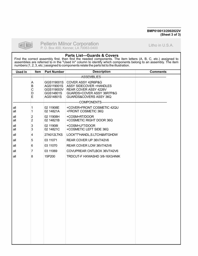
Parts List—Guards & Covers
BMP010013/2002022V(Sheet 3 of 3)
.---------------------------------------------------------------------ASSEMBLIES------------------------------------------------------------------
A GGS119001S COVER ASSY 42R6P&GB AGS119001S ASSY SIDECOVER +HANDLESC GGS119003V REAR COVER ASSY 4226VD GGS14801S GUARDS+COVER ASSY 36R7P&GE AGS14801S GUARDS&COVERS ASSY 36Q
-------------------------------------------------------------------COMPONENTS------------------------------------------------------------------
all 1 02 11908E +COVER=FRONT COSMETIC 42QUall 1 02 14821A +FRONT COSMETIC 36Q
all 2 02 11908H +COSM=RT/DOORall 2 02 14821B +COSMETIC RIGHT DOOR 36Q
all 3 02 11908I +COSM=LFT/DOORall 3 02 14821C +COSMETIC LEFT SIDE 36Q
all 4 27A012LTKS LOCK"T"HANDL,S.LTCH&MTGHDW
all 5 03 11071 REAR COVER UP 36V7/42V6
all 6 03 11070 REAR COVER LOW 36V7/42V6
all 7 03 11069 COVUPREAR CNTLBOX 36V7/42V6
all 8 15P200 TRDCUT-F HXWASHD 3/8-16X3/4NIK
R
Pellerin Milnor CorporationPellerin Milnor CorporationP. O. Box 400, Kenner, LA 70063-0400
Litho in U.S.A.
Item Part Number Description CommentsUsed In
Find the correct assembly first, then find the needed components. The item letters (A, B, C, etc.) assigned toassemblies are referred to in the "Used In" column to identify which components belong to an assembly. The itemnumbers (1, 2, 3, etc.) assigned to components relate the parts list to the illustration.

R
Pe
llerin
Miln
or
Co
rpo
ratio
nP
elle
rin
Miln
or
Co
rpo
ratio
nP.
O.
Bo
x4
00
,K
en
ne
r,L
A7
00
63
-04
00
Litho
inU
.S.A
.
BM
P010034/2
002103V
(Sh
eet
1o
f2)
Gu
ard
sa
nd
Cove
rs
36
02
6V
5J
36026V
5J
1
2 3
2 3
4(8
PL
AC
ES
)

R
Pellerin Milnor CorporationPellerin Milnor CorporationP. O. Box 400, Kenner, LA 70063-0400
Litho in U.S.A.
Item Part Number Description CommentsUsed In
Find the correct assembly first, then find the needed components. The item letters (A, B, C, etc.) assigned toassemblies are referred to in the "Used In" column to identify which components belong to an assembly. The itemnumbers (1, 2, 3, etc.) assigned to components relate the parts list to the illustration.
Parts List—Guards and Covers
BMP010034/2002103V(Sheet 2 of 2)
.
---------------------------------------------------------------------ASSEMBLIES------------------------------------------------------------------
A GGS14808 GUARD + COVER INSTALL 36V5 Mk2
-------------------------------------------------------------------COMPONENTS------------------------------------------------------------------
all 1 AGS14808 FRONT COVER ASSY 36V5
all 2 03 11064 BELTGD-UPPER REAR 36V5
all 3 03 11065 BELTGD-LOWER REAR 36V5
all 4 15P200 TRDCUT-F HXWASHD 3/8-16X3/4NIK

About the Forces Transmitted by Milnor® Washer-extractors
Document ..................... BIWUUI02Specified Date ................. 20001108As-of Date ....................... 20001108Access Date ..................... 20001108
About the Forces Transmitted by Milnor®
Washer-extractorsApplicability...........................WUU
During washing and extracting, all washer-extractors transmit both static and dynamic(cyclic) forces to the floor, foundation, or any other supporting structure. During washing, theimpact of the goods as they drop imparts forces which are quite difficult to quantify. Size for size,both rigid and flexibly-mounted machines transmit approximately the same forces duringwashing. During extracting, rigid machines transmit forces up to 30 times greater than equivalentflexibly-mounted models. The actual magnitude of these forces vary according to several factors:
• machine size,
• final extraction speed,
• amount, condition, and type of goods being processed,
• the liquor level and chemical conditions in the bath preceding extraction, and
• other miscellaneous factors.
Estimates of the maximum force normally encountered are available for each Milnor® modeland size upon request. Floor or foundation sizes shown on any Milnor® document are only foron-grade situations based only on previous experience without implying any warranty, obligation,or responsibility on our part.
1. Rigid MachinesSize for size, rigid washer-extractors naturally require a stronger, more rigid floor,
foundation, or other supporting structure than flexibly-mounted models. If the supporting soilunder the slab is itself strong and rigid enough and has not subsided to leave the floor slabsuspended without support, on grade installations can often be made directly to an existing floorslab if it has enough strength and rigidity to safely withstand our published forces withouttransmitting undue vibration. If the subsoil has subsided, or if the floor slab itself has insufficientstrength and rigidity, a deeper foundation, poured as to become monolithic with the floor slab,may be required. Support pilings may even be required if the subsoil itself is “springy” (i.e., if itsresonant frequency is near the operating speed of the machine). Above-grade installations of rigidmachines also require a sufficiently strong and rigid floor or other supporting structure asdescribed below.
2. Flexibly-mounted MachinesSize for size, flexibly-mounted machines generally do not require as strong a floor,
foundation, or other supporting structure as do rigid machines. However, a floor or othersupporting structure having sufficient strength and rigidity, as described in section 3, isnonetheless vitally important for these models as well.
3. How Strong and Rigid?Many building codes in the U.S.A. specify that laundry floors must have a minimum live
load capacity of 150 pounds per square foot (732 kilograms per square meter). However, evencompliance with this or any other standard does not necessarily guarantee sufficient rigidity. Inany event, it is the sole responsibility of the owner/user to assure that the floor and/or any othersupporting structure exceeds not only all applicable building codes, but also that the floor and/orany other supporting structure for each washer-extractor or group of washer-extractors actually

has sufficient strength and rigidity, plus a reasonable factor of safety for both, to support theweight of all the fully loaded machine(s) including the weight of the water and goods, andincluding the published 360º rotating sinusoidal RMS forces that are transmitted by themachine(s). Moreover, the floor, foundation, or other supporting structure must have sufficientrigidity (i.e., a natural or resonant frequency many times greater than the machine speed with areasonable factor of safety); otherwise, the mentioned 360º rotating sinusoidal RMS forces can bemultiplied and magnified many times. It is especially important to consider all potential vibrationproblems that might occur due to all possible combinations of forcing frequencies (rotatingspeeds) of the machine(s) compared to the natural frequencies of the floor and/or any othersupporting structure(s). A qualified soil and/or structural engineer must be engaged for thispurpose.
Figure 1: How Rotating Forces Act on the Foundation
Typical Machine
Legend
A. Direction of forceB. LoadC. Rotation (Frequency = RPM / 60)
Figure 1 above is intended to depict both on-grade and above-grade installations and isequally applicable to flexibly-mounted washer-extractors, as well as to rigid models installedeither directly on a floor slab or on a foundation poured integrally with the slab. Current machinedata is available from Milnor® upon request. All data is subject to change without notice and mayhave changed since last printed. It is the sole responsibility of every potential owner to obtainwritten confirmation that any data furnished by Milnor® applies for the model(s) and serialnumber(s) of the specific machines.
— End of BIWUUI02 —

<B8DD@C604�!��"�#$E����������������� �������������������������������������������������� �������!��"���#$���%����
Illustration Explanation
Stop! Read the manual first for completeinstructions before continuing.
Do not jack the machine here.Do not lift the machine here.
Use three point or four point lifting asdetermined by the lifting eyes furnished. Rigthe load using lifting cables of sufficient sizeand length to ensure cables are notover-stressed.
Do not lift the machine from one corner or oneside edge.

Illustration Explanation
Do not start this machine until the packingmaterials, lifting brackets, etc. with this tagattached or behind this panel are removed.These materials are painted red. Safety standsor brackets (also painted red) may be providedwith this machine. Do not discard safetystands or brackets
Do not step or stand on this machine part.
Maintain a 25 mm. (1") minimum clearancebetween float clips. Set "low level" so that thebottom of the float is always at least 25mm(1") above the bottom of the float tube.
This motor or pump should rotate in thedirection of the arrow.

Do not start this machine until the part withthis tag is installed on the machine.
Do not remove this component from themachine.
Install the appropriate part here beforeoperating the machine.
Do not pump grease here.
7\_ccQbi _V DQW 9\\ecdbQdY_^c±6�Cdi\U� A�Cdi\U� #&� � $"� F�Cdi\U� Q^T H�Cdi\U GQcXUb�5hdbQSd_bc

During drain and extract, the cylinder mustrotate counterclockwise when viewed fromhere (rear of machine).
During drain and extract, the cylinder mustrotate clockwise when viewed from here(front of machine).
Do not pump grease here.
.
Do not strike shell front of washer-extractorsduring fork lifting. Striking shell front willcause door to leak.
=C9EEAD715�" # $%F �" � #�

Make cold water connection here.
Make hot water connection here.
Make third (reuse) water connection here.
Hold the connection side of the valve with awrench when connecting plumbing.
H 02
H 02
H 02
7\_ccQbi _V DQW 9\\ecdbQdY_^c±6�Cdi\U� A�Cdi\U� #&� � $"� F�Cdi\U� Q^T H�Cdi\U GQcXUb�5hdbQSd_bc

PELLERIN MILNOR CORPORATION
BIWUUI03 (Published) Book specs- Dates: 20030306 / 20030306 / 20030306 Lang: ENG01 Applic: WUU
Avoiding Damage From Allied Remote Chemical DeliverySystemsMilnor® does not manufacture or supply remote chemical delivery systems and this document ismeant only to illustrate some of the possible problems that can be minimized during installationof such systems by the chemical supply company. Milnor washer-extractors and CBW® batchwashers (tunnels) are available with convenient inlets for such systems (see Figure 1). Mostcommon of the types of systems currently used in commercial laundering operations are pumpedchemical systems. Other types, such as constant pressure, re-circulating ring main systems havealso been, and may continue to be used with Milnor equipment.
This document warns about some of the possible hazards posed by chemical systems and listscertain requirements needed to minimize those hazards. The procedures for interfacing with alliedchemical systems and information pertinent to chemical use in general are provided elsewhere inthe product manuals (see Note 1).
Figure 1: Pumped Chemical Inlets on CBW Batch Washer
Note 1: Misuse of laundering chemicals (such as injecting excessive concentrations of chlorine bleach orpermitting acid sours to react with hypo chlorite) due to incorrect formulation can also be hazardous.Information pertinent to chemical use is provided elsewhere in the product manuals.
1. How a Chemical System Can Damage the Machine It ServesMilnor has manufactured washer-extractors and tunnel washers with the same stainless steelspecification since its founding. Every batch of steel used is certified and documented by the steelmill. Testing of samples damaged by corrosion have, in every case, proven the steel to be wellwithin the AISI 304 specification.

Avoiding Damage From Allied Remote Chemical Delivery Systems
PELLERIN MILNOR CORPORATION
Chemical products commonly found in the laundry industry, when used in established dosagesand proper operating parameters, under the auspices of an experienced chemical specialist, shouldproduce satisfactory results, with no consequential detrimental effects. The industry has publishedstandards in Riggs and Sherrill, “Textile Laundering Technology”. However, the stainless steelcan be damaged and even destroyed by abnormal contact with chlorine bleach, hydrofluosilicicacid and other commonly used chemicals, as will occur if chemicals are unintentionally leakedinto the machine, particularly when it is no longer in use and especially when machine surfacesare dry.
Some chemical systems have been found to permit chemicals to dribble from the supply lines, orworse, to siphon from the supply tank into the machine, during operation and long after thesystem is shut down—as after working hours and during weekends. If this occurs, deterioration(rusting) of the stainless steel and damage to any textiles therein will inevitably result. If thiscondition goes undetected, machine damage is likely to be catastrophic. No machine isimmune to such damage.
CAUTION 1 : Equipment and Textile Damage Hazards—Chemicals leaked into themachine, particularly when it is idle can destroy machine components and textiles left in themachine. Pellerin Milnor Corporation accepts absolutely no responsibility for damage to itsequipment or to textiles therein from abnormal contact with chemicals.• Ensure that the chemical system prevents unintentional release of chemicals.
• Inspect regularly for proper operation and evidence of damage.
2. Requirements for Chemical Systems Used With Milnor MachinesIt is the responsibility of the chemical system manufacturer and supplier to ensure that theirsystem is safe for personnel and equipment. Some important points are described below.
2.1. Ensure the System Cannot Siphon.—The supply system must be designed tocounteract any siphoning that could occur as a result of having a sealed supply line between thebottom of the chemical tank and the internal machine connection at the drain trough. As shown inthe Figure 2 examples, if the pump (P) and/or the valving does not provide positive closure andthere is no vacuum breaker protection, siphoning is likely to occur. In each of the Figure 2illustrations, the volume of chemical in the tank above the siphon level (S), and indicated byshading, will flow into the machine.

PELLERIN MILNOR CORPORATION
Figure 2: Siphoning From the Chemical Tank into the MachineExamples
Legend
P. PumpS. Siphon level. Shading indicates the chemical delivery line and tank content that can siphon into
the machine.T. Chemical tank
2.2. Ensure the Chemical Lines Cannot Dribble—The pumped chemical system mayprovide a means of positively closing the chemical line at the pump location, but not at theinjection site. Hence, any concentrated chemical that remains in the injection line between thepump and the machine is free to flow into the machine. Some examples of this are shown inFigure 3.

Avoiding Damage From Allied Remote Chemical Delivery Systems
PELLERIN MILNOR CORPORATION
Figure 3: Dribbling From Chemical Supply Line Into Machine(assumes positive closure at the pump)
Examples
Legend
D. Portion of supply line, the contents of which can dribble into the machineP. PumpT. Chemical tank
3. Design and Installation RecommendationsIt is the responsibility of the chemical system manufacturer and supplier to use whatevermeasures are necessary to ensure that their system is safe for personnel and equipment. Thefollowing are some of the possible methods the manufacturer or supplier may wish to use, asappropriate.
3.1. Siphoning: Positively close the line.—If the pump does not provide positive closurewhen the system is off, employ a shutoff valve in the line to serve this purpose.
3.2. Siphoning: Break the siphon.—Provide an air gap or vacuum breaker in the chemicaldelivery line. This must be located above the “full” line of the tank.
3.3. Dribbling: Flush the entire chemical delivery line.—If any concentrated chemicalthat remains in the injection line between the pump and the machine is free to flow into themachine, employ a system that flushes the entire line between the pump and the injection pointwith fresh water after each injection.

PELLERIN MILNOR CORPORATION
3.4. Dribbling: Locate the entire chemical line below the machine inlet.—Assuming the chemical system does not retain any line pressure and that the pump providespositive closure when the system is off, locate the entire chemical delivery line below the level ofthe chemical inlet. An example of this is shown in Figure 4.
Figure 4: Locating a Pumped Chemical System With PositiveClosure To Protect Against Machine Damage
Example of Correct Placement Legend
I. Chemical inlet onmachine
L. Chemical delivery lineP. Pump with positive
closure when system isoff
T. Chemical tank
4. Guarding Against LeaksAll personnel who may work with the chemical system (e.g., chemical system manufacturer,chemical system supplier, chemical supplier, operator, maintenance personnel) should be vigilantin observing for leaks in the system. When connecting, or reconnecting chemical lines, whether atinstallation, after taking samples, or when replacing components, at a minimum ensure that:
1. the proper components are used,
2. all connections are the proper fit, and
3. all components are securely connected.
CAUTION 2 : Injury and Damage Hazards—Chemicals leaking from a chemical systemmay be corrosive or toxic. Such chemicals can injure personnel and damage equipment.• Use care when connecting chemical lines.
• Inspect regularly for leaks.
— End of BIWUUI03 —

R
Pe
llerin
Miln
or
Co
rpo
ratio
nP
elle
rin
Miln
or
Co
rpo
ratio
nP.
O.
Bo
x4
00
,K
en
ne
r,L
A7
00
63
-04
00
Litho
inU
.S.A
.
BM
P020109/2
002145V
(Sh
eet
1o
f2)
Sa
fety
Pla
ca
rdU
se
an
dP
lac
em
en
t3
60
26
V5
J,
36
02
1C
PE
,N
SP
&V
5J
No
tes:
1
.A
pp
roxim
ate
locati
on
so
fp
lacard
sare
sh
ow
n.
Mo
un
tin
gh
ole
sare
pro
vid
ed
on
mach
ine.
Ifalu
min
um
pla
card
use
#8
self
-tap
pin
gscre
ws.
.R
ep
lace
pla
card
imm
ed
iate
ly,if
rem
oved
or
un
read
ab
le.
2
20
On
To
p
40
5060 10
FRO
NT
VIE
WLEFT
VIE
WRIG
HT
VIE
W
REA
RVIE
W

R
Pellerin Milnor CorporationPellerin Milnor CorporationP. O. Box 400, Kenner, LA 70063-0400
Litho in U.S.A.
Item Part Number Description CommentsUsed In
Find the correct assembly first, then find the needed components. The item letters (A, B, C, etc.) assigned toassemblies are referred to in the "Used In" column to identify which components belong to an assembly. The itemnumbers (1, 2, 3, etc.) assigned to components relate the parts list to the illustration.
Parts List—Safety Placard Placement
BMP020109/2002145V(Sheet 2 of 2)
.
---------------------------------------------------------------------ASSEMBLIES------------------------------------------------------------------
none
-------------------------------------------------------------------COMPONENTS------------------------------------------------------------------
all 10 01 10635A NPLT:SHELL FRONT RIDGID-TCATA
all 20 01 10375B NPLT:ELEC HAZARD SMALL-TCATA
all 40 01 10689A NPLT:BELT HAZARD SM TCATA
all 50 01 10699A NPLT:SERV HZRD-PLYEST-TCATA
all 60 01 10377A NPLT:ELEC HAZARD LG-TCATA

R
Pe
llerin
Miln
or
Co
rpo
ratio
nP
elle
rin
Miln
or
Co
rpo
ratio
nP.
O.
Bo
x4
00
,K
en
ne
r,L
A7
00
63
-04
00
Litho
inU
.S.A
.
BM
P020110/2
002145V
(Sh
eet
1o
f2)
No
tes:
1
.A
pp
roxim
ate
locati
on
so
fp
lacard
sare
sh
ow
n.
Mo
un
tin
gh
ole
sare
pro
vid
ed
on
mach
ine.
Ifalu
min
um
pla
card
use
#8
self
-tap
pin
gscre
ws.
.R
ep
lace
pla
card
im-
med
iate
ly,if
rem
oved
or
un
read
ab
le.
2
40
20
30
10
ISO
Pla
card
ssh
ow
no
nth
isp
ag
e
Sa
fety
Pla
ca
rdU
se
an
dP
lac
em
en
tIS
O3
60
26
V5
J,
36
02
1C
PE
,N
SP
&V
5J
FRO
NT
VIE
WLEFT
VIE
WRIG
HT
VIE
W
REA
RVIE
W

R
Pellerin Milnor CorporationPellerin Milnor CorporationP. O. Box 400, Kenner, LA 70063-0400
Litho in U.S.A.
Item Part Number Description CommentsUsed In
Find the correct assembly first, then find the needed components. The item letters (A, B, C, etc.) assigned toassemblies are referred to in the "Used In" column to identify which components belong to an assembly. The itemnumbers (1, 2, 3, etc.) assigned to components relate the parts list to the illustration.
Parts List—Safety Placard Placement
BMP020110/2002145V(Sheet 2 of 2)
---------------------------------------------------------------------ASSEMBLIES------------------------------------------------------------------
none
-------------------------------------------------------------------COMPONENTS------------------------------------------------------------------
all 10 01 10632X NPLT:WE1 RIGID WARNINGS FR
all 20 01 10375 NPLTE:"WARNING" 2X2
all 30 01 10377 NPLTE:"WARNING" 4X4
all 40 01 10632Y NPLT:WE1 RIGID WARNINGS POLY

R
Pe
llerin
Miln
or
Co
rpo
ratio
nP
elle
rin
Miln
or
Co
rpo
ratio
nP.
O.
Bo
x4
00
,K
en
ne
r,L
A7
00
63
-04
00
Litho
inU
.S.A
.
BM
P020111/2
002145V
(Sh
eet
1o
f2)
Sa
fety
Pla
ca
rdU
se
an
dP
lac
em
en
t3
60
26
V7
J/W
&4
20
26
V6
J/W
No
tes:
1
.A
pp
roxim
ate
locati
on
so
fp
lacard
sare
sh
ow
n.
Mo
un
tin
gh
ole
sare
pro
vid
ed
on
mach
ine.
Use
#8
self
-tap
pin
gscre
ws.
.R
ep
lace
pla
card
imm
ed
iate
ly,if
rem
oved
or
un
read
ab
le.
2
LEFT
VIE
WFRO
NT
VIE
WRIG
HT
VIE
W
REA
RVIE
W
10
40
20
60
50

R
Pellerin Milnor CorporationPellerin Milnor CorporationP. O. Box 400, Kenner, LA 70063-0400
Litho in U.S.A.
Item Part Number Description CommentsUsed In
Find the correct assembly first, then find the needed components. The item letters (A, B, C, etc.) assigned toassemblies are referred to in the "Used In" column to identify which components belong to an assembly. The itemnumbers (1, 2, 3, etc.) assigned to components relate the parts list to the illustration.
Parts List—Safety Placard Placement
BMP020111/2002145V(Sheet 2 of 2)
.
---------------------------------------------------------------------ASSEMBLIES------------------------------------------------------------------
none
-------------------------------------------------------------------COMPONENTS------------------------------------------------------------------
all 10 01 10635A NPLT:SHELL FORNT RIDGID-TCATA
all 20 01 10377A NPLT:ELEC HAZARD LG-TCATA
all 40 01 10689A NPLT:BELT HAZARD SM TCATA
all 50 01 10685A NPLT:BURN HAZARD WARN-TCATA
all 60 01 10699A NPLT:SERV HZRD-PLYEST-TCATA
R
Pe
llerin
Miln
or
Co
rpo
ratio
nP
elle
rin
Miln
or
Co
rpo
ratio
nP.
O.
Bo
x4
00
,K
en
ne
r,L
A7
00
63
-04
00
Litho
inU
.S.A
.
BM
P020112/2
002145V
(Sh
eet
1o
f2)
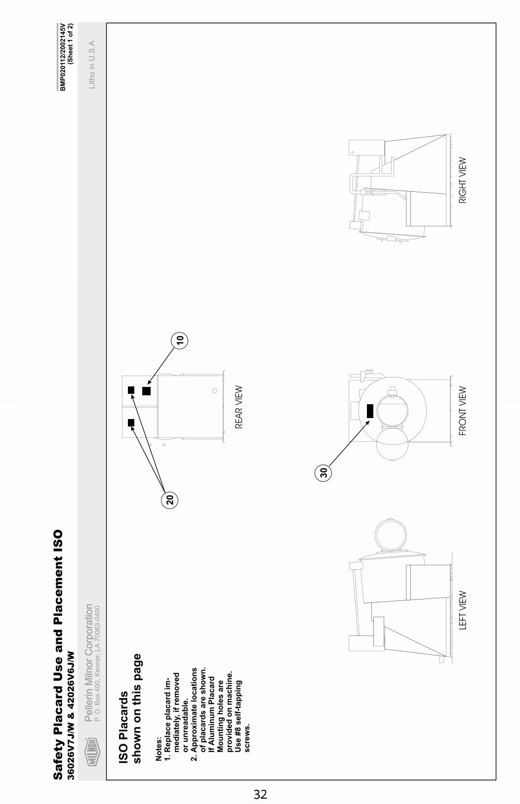
No
tes:
1
.A
pp
roxim
ate
locati
on
so
fp
lacard
sare
sh
ow
n.
IfA
lum
inu
mP
lacard
Mo
un
tin
gh
ole
sare
pro
vid
ed
on
mach
ine.
Use
#8
self
-tap
pin
gscre
ws.
.R
ep
lace
pla
card
im-
med
iate
ly,if
rem
oved
or
un
read
ab
le.
2
20
10
30
ISO
Pla
card
ssh
ow
no
nth
isp
ag
e
Sa
fety
Pla
ca
rdU
se
an
dP
lac
em
en
tIS
O3
60
26
V7
J/W
&4
20
26
V6
J/W
LEFT
VIE
WFRO
NT
VIE
WRIG
HT
VIE
W
REA
RVIE
W

R
Pellerin Milnor CorporationPellerin Milnor CorporationP. O. Box 400, Kenner, LA 70063-0400
Litho in U.S.A.
Item Part Number Description CommentsUsed In
Find the correct assembly first, then find the needed components. The item letters (A, B, C, etc.) assigned toassemblies are referred to in the "Used In" column to identify which components belong to an assembly. The itemnumbers (1, 2, 3, etc.) assigned to components relate the parts list to the illustration.
Parts List—Safety Placard Placement
BMP020112/2002145V(Sheet 2 of 2)
---------------------------------------------------------------------ASSEMBLIES------------------------------------------------------------------
none
-------------------------------------------------------------------COMPONENTS------------------------------------------------------------------
all 10 01 10632X NPLT:WE1 RIGID WARNINGS FR
all 20 01 10377 NPLTE:"WARNING" 4X4
all 30 01 10632Y NPLT:WE1 RIGID WARNINGS POLY


Section 1Service and Maintenance

Preventive Maintenance
PELLERIN MILNOR CORPORATION
BIRQUM01 (Published) Book specs- Dates: 20050302 / 20050302 / 20050302 Lang: ENG01 Applic: RQV
Preventive Maintenance
1. Lubrication GuidelinesAs required by the warranty, to ensure safe operation, and to achieve optimum performance andservice life from Milnor® washer-extractors, the schedules, instructions, and precautions hereinmust be strictly followed.
WARNING 1 : Entangle and Crush Hazard—Belts and pulleys can entangle and crushbody parts.• Lock OFF and tag out power at the wall disconnect before servicing, except where
specifically instructed otherwise in this section.• Insure belt and pulley guards are in place during service procedures.• Permit only qualified maintenance personnel to perform these procedures.
2. 36026V5J Main Bearing Maintenance36026V5J main bearing housings are oil-filled and require periodic draining and refilling (seebelow). 42026V6J bearing housings are grease filled and require periodic greasing of seals andbearings (See “Lubrication Precautions” and “42026V6J Main Bearing Maintenance” below).
See the appropriate “MAIN BEARING ASSEMBLY” (see Table of Contents) during thisprocedure.
1. Remove the drain plug on the bottom of the main bearing housing and allow the bearinghousing to drain completely (Figure 4). Inspect the leak-off, drained oil, and magnetic drainplug for water and/or metal particles. Install the drain plug. Water and/or metal particles canindicate worn or damaged seals and bearings.
2. Locate the two 1/2" plastic tubes secured to the electrical control chassis (Figure 5). Clean thesurrounding area and remove the cork stoppers from each.
3. Strictly following lubrication specifications, refill the bearing housing. After refilling thebearing housing, re-install the cork stoppers and clean any excess lubricant from the machine.
3. Lubrication Precautions (42026V6J only)CAUTION 2 : Bearing and Seal Damage Hazard—Mixing different base greases cancause bearing and seal damage.• Consult lubricant manufacturer before using non-specified lubricants.
WARNING 3 : Entangle and Crush Hazard—Belts and pulleys can entangle and crushbody parts. Power is ON and cylinder is turning during the following procedure.• Insure belt and pulley guards are in place during service procedure.
1. Do not use a pneumatic grease gun. Pump grease slowly while cylinder is rotating. Take 10-12 seconds to complete each stroke. A grease gun can build up extremely high pressurewhich will force the seals out of position and cause them to leak, even though both the sealand bearing cavities are equipped with spring loaded relief plugs.
2. Apply the quantity of grease called for in the checklist. Over-lubrication can be as damagingas under-lubrication. Where quantities are stated in strokes, one stroke of the grease gun isassumed to provide .0624 fluid ounce (by volume) (1.77 grams) of grease. Therefore, onefluid ounce (28.3 grams) of grease would be provided by 16 strokes of the grease gun.

Preventive Maintenance
PELLERIN MILNOR CORPORATION
Determine the flow rate of your grease gun by pumping one ounce into a calibrated container.If fewer than 16 strokes are required, all quantities of strokes in the chart should be reducedaccordingly, and if more than 16 strokes are required, the number of strokes should beincreased. Before starting lubrication, make sure grease gun is working and that you get a fullcharge of grease with every stroke.
3. Do not pump grease in until it oozes out of the spring loaded relief plugs. Plugs bleed outexcess grease and help prevent abnormal pressures from building up in the housing duringoperation (especially when the machine is first commissioned and after each lubrication).Plugs will not protect against over-lubrication.
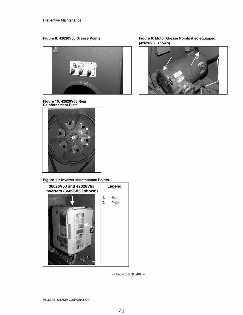
4. 42026V6J Main Bearing MaintenanceSee the appropriate “MAIN BEARING ASSEMBLY” (see Table of Contents) during thisprocedure.
1. Locate the seal and bearing grease fittings (Figure 8).
2. Place the machine in a wash step (see operating manual).
3. With the cylinder turning, grease the seals and bearings as called for in the PreventiveMaintenance Checklist.

Preventive Maintenance
PELLERIN MILNOR CORPORATION
5. Preventive Maintenance ScheduleTable 1: Preventive Maintenance Checklist
Component Action Frequency Specifications/Figure
BearingHousing
Oil Remove fill, vent and drainstoppers. Refill 22 ounces (634grams)
Every fourmonths
High quality SAE 30 to 50(ISO 100 - 220) single weightheavy duty motor oil (non-detergent if available). See"Oil Drain and Water Leak-off" and also see"30022C4x,..Fill/Vent Hoses"
Seals One stroke 0.06 ounces (1.77grams) at one location
Monthly(see Note 1)
Bearings Two strokes, 0.12 ounces (3.54grams) at two locations
Monthly
Shell Alvania (or equivalent)See "42026V6J Grease Points"
Belts and pulleys Check for wear, replace asrequired
Monthly See "Drive Train Pulleys andBelts"
Drive Train
Motors (ifequipped withgrease fittings)(See Note 2)
See "Baldor MotorMaintenance...," in this manual(See Note 3)
Every threeMonths
See motor nameplate. If notspecified, use Shell Alvania(or equivalent). See "MotorGrease Points"
DriveInverter
Inverter Verify fan operation. Vacuumout inverter vents.
Monthly See "Inverter MaintenancePoints"
Hoses,Clamps, andConnections
Inlet, drain, andchemical hosesand connections
Check for leaks, cracks andbulges
Monthly
Bolts Foundation Check bolt tightness and wear Monthly See dimensional drawings
Rear bearingreinforcementplate andthroughoutmachine
See "30022C4x,...RearReinforcement Plate" for36021C4E and 36026V5Jmachines, or "42026V6J RearReinforcement Plate" for42026V6J machines.
Note 1: Monthly/200 hours = Once a month or once every 200 operating hours, whichever comes first.
Note 2: Do not over-lubricate motors. Over-lubrication of a motor can seriously damage it by forcinggrease into motor windings.
Note 3: If motor manufacturer's instructions conflict with manual section MSSM0274AE, followmanufacturers instructions. Motors are warranted by the manufacturers, not by Milnor.
6. Correcting Belt SlippageThe drive train has a special belt tension sleeve, allowing additional tension to be applied to aworn, slipping belt to extend the drive belt life. Replace the belt when the belt starts to slip againafter installing the belt tension sleeve.
1. Slacken and slip the drive belts off of the motor pulley by placing a 2 X 4 under the motorplatform and pulling upward against the spring as shown in Figure 1.
2. Remove both shaft collars and slip the motor mount shaft out of its brackets (Figure 1).

Preventive Maintenance
PELLERIN MILNOR CORPORATION
3. Reinsert the motor mount shaft, slipping the belt tension sleeve over the motor mount shaftduring installation as shown in Figure 2.
Figure 1: Correcting Belt Slippage
Raising motor platform Motor mount shaft
Belt tension sleeve and motor mount shaft Legend
.
1. Motor mount shaft2. Belt tension sleeve3. Shaft collars
Figure 2: Belt Tension Sleeve Over Motor MountShaft
Figure 3: Assembled Sleeve Over Motor Shaft

Preventive Maintenance
PELLERIN MILNOR CORPORATION
7. Maintenance Points
Figure 4: 30022C4x, 30022T5x, 36021C4E and36026V5J Oil Drain and Water Leak-off
Figure 5: 30022C4x, 30022T5x,36021C4E and 36026V5J OilFill/Vent Hoses (use either hosefor filling)
Figure 6: Drive Train Pulleys andBelts (30022V6J shown)
Figure 7: 30022C4x, 30022T5x, 30022V6J, 36021C4Eand 36026V5J Rear Bearing Reinforcement Plate(30022VxJ shown)
Preventive Maintenance
PELLERIN MILNOR CORPORATION
Figure 8: 42026V6J Grease Points Figure 9: Motor Grease Points if so equipped,(42026V6J shown)
Figure 10: 42026V6J RearReinforcement Plate
Figure 11: Inverter Maintenance Points
36026V5J and 42026V6JInverters (36026V5J shown)
Legend
1
2
.
1. Fan2. Vent
— End of BIRQUM01 —

Document .................... BIRQVM01Specified Date ................. 20010822As-of Date ....................... 20010822Access Date..................... 20010822
Applicability............................RQV
�� ��� ����������������������������������������������������
Language Code.................... ENG01
The motors on 36 and 42Vxx machines rest on a spring tensioned motor mount plate. Anymisalignment between this motor mount and the drive pulley results in excessive drive belt twistand stress, greatly reducing belt life. Check motor mount to drive pulley alignment wheneverexcessive drive train dust is noted, or whenever any type of drive train service (belt replacement,main bearing or motor replacement) is required.
F0A=8=6 ) 4]cP]V[T P]S BTeTa 7PiPaSb—Contact with moving componentsnormally isolated by guards, covers, and panels, can entangle and crush your limbs.These components move automatically.• Lock out and tag out power at the main machine disconnect before servicing, or in
accordance with factory service procedures.
Figure 1: Drive Pulley and Motor Alignment
� ��������� ���!This procedure requires a 4' contractors square and hand tools.
!� �� ������"��Shims are available under the following part number; 02 02822-(0.78").
"� �#�!���������������
1. Lock out and tag out power to the machine.
2. Remove rear pulley cover.
3. Set the angle of the contractors square at 90 degrees.
4. Hold the square flush against the drive pulley (Figure 2 and Figure 3).
5. If the bottom straight edge of the contractors square does not rest flush against the motor (asshown in the Figure 4 example), note which end of the motor must be shimmed to eliminatethe gap.
6. Loosen the bolt securing the motor mount plate to the channel weldment. Bolt should be justloose enough to allow shims to be inserted between the motor platform and the channelweldment beneath (Figure 5).

1\YW^Y^W #& Q^T $"Fhh =_d_b =_e^d @\QdU gYdX dXU 4bYfU @e\\Ui
7. The shims are made in a u-shape to fit around the bolt. Estimate the thickness needed and slipthe appropriate number of shims around the bolt.
8. Tighten bolt and measure again with the contractors square. Repeat steps 7 and 8, adding orsubtracting shims as required until the straight edge touches the motor top at all points (or asclose as possible with the shims used).
Figure 2: Checking Pulley/MotorAlignment
Figure 3: Contractors SquareTouching Both Sides of the Pulley
Figure 4: Close-up of ContractorsSquare Showing Degree of MotorMisalignment
Figure 5: Inserting Shims Between Motor MountPlate and Channel Weldment
— End of BIRQVM01 —

MSSM0101CE/9906AV (1 of 19)
ÈFASTENER TORQUE REQUIREMENTS
The specifications in this section apply to 1/4 inch and larger Unified National fine and coarse fasteners used onMilnor® machines. This information is to be used only when torque specifications are not stated in the installationor service instructions.
When tightening applicable fastener, abide by the follow-ing precautions:
1. Always use new fasteners. Replace bolts, nuts, flat wash-ers, and lock washers in the order shown on the partsdrawing.
2. Unless otherwise specified, use:
• Loctite® 271 threadlocker or equivalent for bearinghousing mounting bolts from one half to one inch in di-
ameter.
• Loctite® 277 threadlocker or equivalent for bearinghousing mounting bolts of one inch diameter or larger.
• Loctite® 242 threadlocker for all other fastenersrequiring thread locking compound.
3. Use a torque wrench to assure proper tightness.
4. Never lubricate fasteners. The values specified herein aremaximum recommended torques and are calculated frompublished ASTM and SAE data. Actual allowable torquesare application dependent and can vary for many reasons,(joint types, gaskets, etc.). Use these values as a guide.
5. Although FIGURE 1 depicts hex head bolts, the table applies to all head types.
ÊFasteners and ThreadlockerËHow Fasteners Loosen —Standard threaded fasteners are manufactured with a clearance fit for easy assem-bly. With the fastener at the proper torque, 85% of the tightening torque is absorbed in the threads and under thefastener head. The remaining 15% provides the friction that prevents the thread from slipping. When this friction isovercome (by bending, thermal expansion, internal pressures, functional loads, or impact) the thread slips and loos-ens. Although higher torques reduce the likelihood of thread slippage, if slippage occurs, the threads unwind andthe fastener loosens. Once thread slippage begins, vibration increases the rate of loosening.ËPreventing Loosening —The most effective way to prevent loosening of threaded parts is by proper appli-cation of a threadlocking compound. Threadlocker provides lubrication during assembly, then hardens to seal thethreads against corrosion and provide resistance to thread slippage.
ÎFIGURE 1 (MSSM0101CE)
ÎFastener Grade Markings

ÊApplying Threadlocker
NOTE: The following threadlocker information andillustrations are excerpts from the Loctite® User’sGuide and are used with permission.
For maximum strength, threadlocker must fill the threadvoids completely, as shown in FIGURE 2. Organic or petro-leum solvent will remove excess uncured adhesive fromjoints. Consult information below for the specific fastener ap-plication.
ËBolts and Nuts —See FIGURE 3.
1. Clean all threads (bolt and nut) with cleaning solvent.
2. Spray all threads with Loctite® Primer N. Allow to dry.
3. Insert bolt into through hole assembly.
4. Apply several drops of threadlocker onto bolt engage-ment area.
5. Assemble and tighten nut to correct torque for the threadlocker.
ËBlind Holes —See FIGURE 4.
1. Clean all threads (bolt and nut) with cleaning solvent.
2. Spray all threads with Loctite® Primer N. Allow to dry.
3. Squirt several drops down female threads into bottom ofhole.
4. Apply several drops to bolt.
5. Tighten to correct torque for the threadlocker.
ÎFIGURE 2 (MSSM0101CE)
ÎCorrect Threadlocker Use
Apply here
Not here
ÎFIGURE 3 (MSSM0101CE)
ÎApplying Threadlocker toThrough Hole
Ontothreads
Ontothreads
ÎFIGURE 4 (MSSM0101CE)
ÎApplying Threadlocker to Blind Holes
MSSM0101CE/9906AV (2 of 19)

ËRemoving Fasteners
High strength threadlockers like Loctite® 271 (or equivalent)may be weakened by heating to at least 500o F (260o C) asfollows.
1. Apply localized heat to fastener as shown in FIGURE 5.
2. Disassemble while hot. Once disassembled, the cured ad-hesive can be removed with Loctite® Gasket Remover#790 (or equivalent).
ÏCarbon Steel Fasteners
ÏAll values in foot pounds and (Newton meters)
Nominalbolt size
GradeDesignation andStandard
Zinc orCadmiumPlated
If instructions call for :
Loctite222 or262
Loctite242
Loctite271
Loctite272
Loctite277
Bare
1/4 - 20 SAE Grade 1ASTM A307
2.5(3.39)
3.0(4.06)
3.3(4.47)
3.6(4.88)
4.6(6.23)
4.3(5.83)
3.3(4.47)
SAE Grade 2 4.1(5.56)
4.9(6.64)
5.5(7.45)
6.0(8.13)
7.7(10.44)
7.1(9.63)
5.5(7.46)
SAE Grade 4 4.8(6.50)
5.8(7.86)
6.4(8.67)
7.0(9.49)
9.0(12.20)
8.3(11.25)
6.4 (8.67)
SAE Grade 5ASTM A449
6.3(8.54)
7.6(10.3)
8.4(11.38)
9.3(12.60)
11.8(15.99)
11.0(14.91)
8.4(11.39)
SAE Grade 7 7.9(10.7)
9.4(12.7)
10.5(14.23)
11.5(15.59)
14.7(19.93)
13.6(18.44)
10.5(14.23)
SAE Grade 8ASTM A354 GradeBD
8.9(12.0)
10.7(14.5)
11.9(16.13)
13.1(17.76)
16.6(22.50)
15.4(20.88)
11.9 (16.13)
ASTM A354 GradeBC
7.9(10.7)
9.4(12.7)
10.5(14.23)
11.5(15.59)
14.7(19.93)
13.6(18.44)
10.5 (14.23)
ÎFIGURE 5 (MSSM0101CE)
ÎRemoving High Strength Threadlocker
FASTENER TORQUE REQUIREMENTS MSSM0101CE/9906AV (3 of 19)

ÏAll values in foot pounds and (Newton meters)
Nomi-nal boltsize
Grade Designationand Standard
Zinc orCadmiumPlated
If instructions call for :
Loctite222 or262
Loctite242
Loctite271
Loctite272
Loctite277
Bare
1/4 - 28 SAE Grade 1ASTM A307
2.8(3.80)
3.4(4.61)
3.8(5.15)
4.1(5.56)
5.3(7.18)
4.9(6.64)
3.8(5.15)
SAE Grade 2 4.7(6.37)
5.6(7.60)
6.3(8.54)
6.9(9.36)
8.8(11.93)
8.1(10.98)
6.3(8.54)
SAE Grade 4 5.5(7.46)
6.6(8.95)
7.3(9.90)
8.1(10.98)
10.3(13.96)
9.5(12.88)
7.3(9.90)
SAE Grade 5ASTM A449
7.3(9.90)
8.7(11.80)
9.7(13.15)
10.7(14.50)
13.6(18.44)
12.6(17.08)
9.7(13.15)
SAE Grade 7 8.9(12.07)
10.7(14.50)
11.9(16.13)
13.1(17.76)
16.6(22.51)
15.4(20.88)
11.9(16.13)
SAE Grade 8ASTM A354 GradeBD
10.2(13.83)
12.2(16.54)
13.6(18.44)
15.0(20.34)
19.0(25.76)
17.7(23.99)
13.6(18.44)
ASTM A354 GradeBC
— — — — — — —
ÏAll values in foot pounds and (Newton meters)
Nominalbolt size
Grade Designationand Standard
Zinc orCadmiumPlated
If instructions call for :
Loctite222or262
Loctite242
Loctite271
Loctite272
Loctite277
Bare
5/16 - 18 SAE Grade 1ASTM A307
5.1(6.91)
6.2(8.40)
6.8(9.22)
7.5(10.17)
9.6(13.02)
8.9(12.07)
6.8(9.22)
SAE Grade 2 8.5(11.52)
10.2(13.83)
11.3(15.32)
12.5(16.95)
15.9(21.56)
14.7(19.93)
11.3(15.32)
SAE Grade 4 10.0(13.56)
12.0(16.27)
13.3(18.03)
14.6(19.79)
18.6(25.22)
17.3(23.46)
13.3(18.03)
SAE Grade 5ASTM A449
13.0(17.63)
15.6(21.15)
17.4(23.60)
19.1(25.90)
24.3(32.95)
22.6(30.64)
17.4(23.60)
SAE Grade 7 16.1(21.83)
19.3(26.17)
21.5(29.15)
23.6(31.99)
30.1(40.81)
27.9(37.83)
21.5(29.15)
SAE Grade 8 ASTMA354 Grade BD
18.5(25.08)
22.1(29.96)
24.6(33.35)
27.1(36.74)
34.5(46.78)
32.0(43.39)
24.6(33.35)
ASTM A354 GradeBC
16.1(21.83)
19.3(26.17)
21.5(29.15)
23.6(31.99)
30.1(40.81)
27.9(37.83)
21.5(29.15)
MSSM0101CE/9906AV (4 of 19)

ÏAll values in foot pounds and (Newton meters)
Nominalbolt size
Grade Designationand Standard
ZincorCadmiumPlated
If instructions call for :
Loctite222 or262
Loctite242
Loctite271
Loctite272
Loctite277
Bare
5/16 - 24 SAE Grade 1ASTM A307
5.6(7.59)
6.7(9.08)
7.4(10.03)
8.2(11.12)
10.4(14.10)
9.6(13.01)
7.4(10.03)
SAE Grade 2 9.4(12.74)
11.3(15.32)
12.5(16.94)
13.8(18.71)
17.5(23.73)
16.3(22.09)
12.5(16.94)
SAE Grade 4 11.0(14.91)
13.2(17.90)
14.6(19.79)
16.1(21.83)
20.5(27.79)
19.0(25.76)
14.6(19.79)
SAE Grade 5ASTM A449
14.4(19.52)
17.2(23.32)
19.1(25.90)
21.1(28.60)
26.8(36.35)
24.9(33.76)
19.1(25.90)
SAE Grade 7 17.9(24.27)
21.4(29.01)
23.8(32.27)
26.2(35.52)
33.4(45.28)
31.0(42.03)
23.8(32.27)
SAE Grade 8ASTM A354 GradeBD
20.4(27.66)
24.4(33.08)
27.1(36.74)
29.9(40.54)
38.0(51.52)
35.3(47.86)
27.1(36.74)
ASTM A354 GradeBC
— — — — — — —
ÏAll values in foot pounds and (Newton meters)
Nominalbolt size
GradeDesignation andStandard
Zinc orCadmiumPlated
If instructions call for :
Loctite222 or262
Loctite242
Loctite271
Loctite272
Loctite277
Bare
3/8 - 16 SAE Grade 1ASTM A307
9.0(12.20)
10.8(14.64)
12.0(16.27)
13.1(17.76)
16.7(22.64)
15.5(21.01)
12.0(16.27)
SAE Grade 2 14.9(20.20)
17.9(24.27)
19.9(26.98)
21.9(29.69)
27.9(37.83)
25.9(35.11)
19.9(26.98)
SAE Grade 4 17.8(24.13)
21.3(28.88)
23.7(32.13)
26.0(35.25)
33.1(44.87)
30.8(41.76)
23.7(32.13)
SAE Grade 5ASTM A449
23.2(31.45)
27.8(37.69)
30.9(41.89)
34.0(46.09)
43.3(58.70)
40.2(54.50)
30.9(41.89)
SAE Grade 7 28.7(38.91)
34.4(46.64)
38.2(51.79)
42.0(56.94)
53.5(72.54)
49.7(67.39)
38.2(51.79)
SAE Grade 8ASTM A354Grade BD
32.7(44.33)
39.2(53.15)
43.6(59.11)
48.0(65.08)
61.0(82.70)
56.7(76.87)
43.6(59.11)
ASTM A354Grade BC
28.7(38.91)
34.4(46.64)
38.2(51.79)
42.0(56.94)
53.5(72.54)
49.7(67.39)
38.2(51.79)
FASTENER TORQUE REQUIREMENTS MSSM0101CE/9906AV (5 of 19)

ÏAll values in foot pounds and (Newton meters)
Nominalbolt size
Grade Designationand Standard
Zinc orCadmiumPlated
If instructions call for :
Loctite222 or262
Loctite242
Loctite271
Loctite272
Loctite277
Bare
3/8 - 24 SAE Grade 1ASTM A307
10.2 (13.83)
12.2(16.54)
13.6(18.44)
15.0(20.33)
19.0(25.76)
17.7(24.00)
13.6(18.44)
SAE Grade 2 16.9(22.91)
20.3(27.52)
22.5(30.52)
24.8(33.62)
31.5(42.70)
29.3(39.73)
22.5(30.50)
SAE Grade 4 20.0(27.11)
24.0(32.54)
26.7(36.20)
29.4(39.86)
37.4(50.70)
34.7(47.04)
26.7(36.20)
SAE Grade 5ASTM A449
26.2(35.52)
31.4(42.57)
34.9(47.32)
38.4(52.06)
48.9(66.30)
45.4(61.55)
34.9(47.32)
SAE Grade 7 32.3(43.79)
38.8(52.60)
43.1(58.44)
47.4(64.26)
60.4(81.89)
56.1(76.06)
43.1(58.43)
SAE Grade 8ASTM A354 GradeBD
36.9(50.02)
44.3(60.06)
49.2(66.70)
54.1(73.35)
68.9(93.41)
64.0(86.77)
49.2(66.70)
ASTM A354 GradeBC
— — — — — — —
ÏAll values in foot pounds and (Newton meters)
Nominalbolt size
Grade Designationand Standard
Zinc orCadmium-Plated
If instructions call for :
Loctite222 or262
Loctite242
Loctite271
Loctite272
Loctite277
Bare
7/16 - 14 SAE Grade 1ASTM A307
14.0(18.98)
17.0(23.04)
19.14(25.95)
21.0(28.47)
27.0(36.60)
25.0(33.89)
19.0(25.76)
SAE Grade 2 24.0(32.54)
28.8(39.05)
32.0(43.39)
35.2(47.72)
44.8(60.74)
41.6(56.40)
32.0(43.39)
SAE Grade 4 28.3(38.37)
34.0(46.10)
37.7(51.11)
41.5(56.27)
52.8(71.59)
49.1(66.57)
37.7(51.11)
SAE Grade 5ASTM A449
37.1(50.30)
44.5(60.33)
49.5(67.11)
54.4(73.76)
69.3(93.96)
64.3(87.18)
49.5(67.11)
SAE Grade 7 45.9(62.23)
55.1(74.70)
61.3(83.11)
67.4(91.38)
85.8(116.33)
79.6(107.92)
61.3(83.11)
SAE Grade 8ASTM A354 GradeBD
52.5(71.18)
63.0(85.41)
70.0(94.90)
77.0(104.40)
98.0(132.87)
91.0(123.38)
70.0(94.90)
ASTM A354 GradeBC
45.7(61.96)
54.9(74.43)
61.0(82.70)
67.1(90.97)
85.4(115.79)
79.3(107.52)
61.0(82.70)
MSSM0101CE/9906AV (6 of 19)

ÏAll values in foot pounds and (Newton meters)
Nominalbolt size
GradeDesignation andStandard
Zinc orCadmiumPlated
If instructions call for :
Loctite222 or262
Loctite242
Loctite271
Loctite272
Loctite277
Bare
7/16 - 20 SAE Grade 1ASTM A307
16.0(21.70)
19.2(26.03)
21.3(28.88)
23.5(31.86)
29.9(40.54)
27.7(37.56)
21.3(28.88)
SAE Grade 2 26.9(36.48)
32.2(43.66)
35.8(48.54)
39.4(53.42)
50.1(67.93)
46.6(63.18)
35.8(48.54)
SAE Grade 4 31.6(42.84)
37.9(51.39)
42.1(57.08)
46.3(62.77)
59.0(79.99)
54.7(74.16)
42.1(57.08)
SAE Grade 5ASTM A449
41.4(56.13)
49.7(67.38)
55.2(74.84)
60.8(82.43)
77.3(104.80)
71.8(97.35)
55.2(74.84)
SAE Grade 7 51.3(69.55)
61.5(83.38)
68.4(92.74)
75.2(101.96)
95.7(129.75)
88.9(120.53)
68.4(92.74)
SAE Grade 8ASTM A354Grade BD
58.2(78.90)
69.9(94.77)
77.7(105.35)
85.4(115.78)
108.7(147.37)
101.0(136.94)
77.7(105.35)
ASTM A354 Grade BC
— — — — — — —
ÏAll values in foot pounds and (Newton meters)
Nominalbolt size
GradeDesignation andStandard
Zinc orCadmiumPlated
If instructions call for :
Loctite222or262
Loctite242
Loctite271
Loctite272
Loctite277
Bare
1/2 - 13 SAE Grade 1ASTM A307
22.0(29.83)
26.0(35.25)
29.38(39.83)
32.0(43.39)
41.0(55.59)
38.0(51.52)
29.0(39.32)
SAE Grade 2 36.6(49.62)
43.9(59.52)
48.8(66.16)
53.6(72.67)
68.3(92.60)
63.4(85.96)
48.8(66.16)
SAE Grade 4 43.1(58.44)
51.8(70.23)
57.5(77.96)
63.3(85.82)
80.5(109.14)
74.8(101.42)
57.5(77.96)
SAE Grade 5ASTM A449
56.7(76.87)
68.1(92.33)
75.6(102.5)
83.2(112.80)
105.9(143.58)
98.3(133.27)
75.6(102.50)
SAE Grade 7 69.8(94.64)
83.8(113.62)
93.1(126.23)
102.4(138.84)
130.4(176.80)
121.1(164.19)
93.1(126.23)
SAE Grade 8ASTM A354Grade BD
79.7(108.05)
95.6(129.62)
106.3(144.12)
116.9(158.50)
148.8(201.75)
138.1(187.24)
106.3(144.12)
ASTM A354Grade BC
69.8(94.64)
83.8(113.62)
93.1(126.23)
102.4(138.84)
130.4(176.80)
121.1(164.19)
93.1(126.23)
FASTENER TORQUE REQUIREMENTS MSSM0101CE/9906AV (7 of 19)

ÏAll values in foot pounds and (Newton meters)
Nominalbolt size
Standard andGrade Designation
Zinc orCadmiumPlated
If instructions call for :
Loctite222 or262
Loctite242
Loctite271
Loctite272
Loctite277
Bare
1/2 - 20 SAE Grade 1ASTM A307
24.8(33.62)
29.8(40.40)
33.1(44.88)
36.4(49.35)
46.4(62.91)
43.1(58.44)
33.1(44.88)
SAE Grade 2 41.3(56.00)
49.5(67.11)
55.0(74.57)
60.5(82.02)
77.0(104.40)
71.5(96.94)
55.0(74.57)
SAE Grade 4 48.8(66.16)
58.5(79.32)
65.0(88.13)
71.5(96.94)
91.0(123.38)
84.5(114.57)
65.0(88.13)
SAE Grade 5ASTM A449
63.8(86.50)
76.5(103.72)
85.0(115.24)
93.5(126.77)
119.0(161.34)
110.5(149.82)
85.0(115.24)
SAE Grade 7 78.8(106.84)
94.5(128.12)
105.0(142.36)
115.5(156.60)
147.0(199.30)
136.5(185.07)
105.0(142.36)
SAE Grade 8ASTM A354 GradeBD
90.0(122.02)
108.0(146.43)
120.0(162.70)
132.0(179.00)
168.0(277.78)
156.0(211.51)
120.0(162.70)
ASTM A354 GradeBC
— — — — — — —
ÏAll values in foot pounds and (Newton meters)
Nominalbolt size
Grade Designationand Standard
Zinc orCadmiumPlated
If instructions call for :
Loctite222 or 262
Loctite242
Loctite271
Loctite272
Loctite277
Bare
9/16 - 12 SAE Grade 1ASTM A307
32.0(43.39)
38.0(51.52)
42.19(57.20)
46.0(62.37)
59.0(80.00)
55.0(74.57)
42(56.94)
SAE Grade 2 52.7(71.45)
63.3(85.82)
70.3(95.31)
77.3(104.80)
98.4(133.41)
91.4(123.92)
70.3(95.31)
SAE Grade 4 62.2(84.33)
74.7(101.28)
83.0(112.53)
91.3(123.79)
116.2(157.55)
107.9(146.30)
83.0(112.53)
SAE Grade 5ASTM A449
81.7(110.77)
98.1(133.00)
109.0(147.78)
119.9(162.56)
152.6(206.90)
141.7(192.17)
109.0(147.78)
SAE Grade 7 100.7(136.53)
120.9(163.92)
134.3(182.09)
147.7(200.25)
188.0(254.89)
174.6(236.73)
134.3(182.09)
SAE Grade 8ASTM A354 GradeBD
115.0(155.92)
138.0(187.10)
153.3(207.85)
168.6(228.59)
214.6(290.96)
199.3(270.21)
153.3(207.85)
ASTM A354 GradeBC
100.7(136.53)
120.9(163.92)
134.3(182.09)
147.7(200.25)
188.0(254.89)
174.6(236.73)
134.3(182.09)
MSSM0101CE/9906AV (8 of 19)

ÏAll values in foot pounds and (Newton meters)
Nominalbolt size
Grade Designationand Standard
Zinc orCadmiumPlated
If instructions call for:
Loctite222 or262
Loctite242
Loctite271
Loctite272
Loctite277
Bare
9/16 - 18 SAE Grade 1ASTM A307
35.3(47.86)
42.4(57.49)
47.1(63.86)
51.8(70.23)
66.0(89.48)
61.2(82.98)
47.1(63.86)
SAE Grade 2 59.1(80.13)
70.9(96.13)
78.8(106.84)
86.6(117.41)
110.3(149.55)
102.4(138.84)
78.8(106.84)
SAE Grade 4 69.6(94.36)
83.5(113.21)
92.8(125.82)
102.1(138.43)
129.9(176.12)
120.7(163.65)
92.8(125.85)
SAE Grade 5ASTM A449
91.2(123.65)
109.5(148.46)
121.6(164.87)
133.8(181.40)
170.3(230.90)
158.1(214.36)
121.6(164.87)
SAE Grade 7 112.3(152.26)
134.8(182.76)
149.8(203.10)
164.7(223.30)
209.7(284.32)
194.7(263.98)
149.8(203.10)
SAE Grade 8ASTM A354 GradeBD
128.7(174.61)
154.4(209.34)
171.6(232.66)
188.7(255.84)
240.2(325.67)
223.0(302.35)
171.6(232.66)
ASTM A354 GradeBC
— — — — — — —
ÏAll values in foot pounds and (Newton meters)
Nominalbolt size
Grade Designationand Standard
Zinc orCadmiumPlated
If instructions call for:
Loctite222 or262
Loctite242
Loctite271
Loctite272
Loctite277
Bare
5/8 - 11 SAE Grade 1ASTM A307
44(59.66)
52(70.50)
58.2(78.90)
64(86.77)
81(109.82)
76(103.04)
58(78.64)
SAE Grade 2 72.7(98.57)
87.2(118.23)
96.9(131.38)
106.6(144.53)
135.6(183.85)
125.9(170.70)
96.9(131.38)
SAE Grade 4 86.1(116.74)
103.4(140.19)
114.8(155.65)
126.3(171.24)
160.8(218.02)
149.3(202.42)
114.8(155.65)
SAE Grade 5ASTM A449
112.5(152.53)
135.0(183.04)
150.0(203.37)
165.0(223.71)
210.0(284.72)
195.0(264.38)
150.0(203.37)
SAE Grade 7 138.9(188.32)
166.6(225.88)
185.2(251.10)
203.7(276.18)
259.2(351.43)
240.7(326.35)
185.2(251.10)
SAE Grade 8ASTM A354 GradeBD
158.8(215.30)
190.5(258.28)
211.7(287.03)
232.9(315.77)
296.4(401.86)
275.2(373.12)
211.7(287.03)
ASTM A354 GradeBC
139.2(188.73)
167.0(226.42)
185.5(251.50)
204.1(276.72)
259.8(352.24)
241.2(327.02)
185.5(251.50)
FASTENER TORQUE REQUIREMENTS MSSM0101CE/9906AV (9 of 19)

ÏAll values in foot pounds and (Newton meters)
Nominalbolt size
Grade Designationand Standard
Zinc orCadmiumPlated
If instructions call for:
Loctite222 or262
Loctite242
Loctite271
Loctite272
Loctite277
Bare
5/8 - 18 SAE Grade 1ASTM A307
49.5(67.11)
59.4(80.54)
66.0(89.48)
72.6(98.43)
92.4(125.27)
85.8(116.33)
66.0(89.48)
SAE Grade 2 82.6(112.00)
99.1(134.36)
110.2(149.41)
121.2(164.33)
154.2(209.07)
143.2(194.15)
110.2(149.41)
SAE Grade 4 97.3(131.92)
116.7(158.22)
129.7(175.85)
142.7(193.48)
181.6(246.22)
168.6(228.59)
129.7(175.85)
SAE Grade 5ASTM A449
127.7(173.14)
153.3(207.85)
170.3(230.90)
187.3(253.95)
238.4(323.23)
221.4(300.18)
170.3(230.90)
SAE Grade 7 157.6(213.68)
189.1(256.39)
210.2(285.00)
231.2(313.47)
294.2(398.88)
273.2(370.41)
210.2(285.00)
SAE Grade 8ASTM A354 GradeBD
179.9(243.91)
215.9(292.72)
239.8(325.13)
263.8(357.66)
335.8(455.28)
311.8(422.74)
239.8(325.13)
ASTM A354 GradeBC
— — — — — — —
ÏAll values in foot pounds and (Newton meters)
Nominalbolt size
Grade Designationand Standard
Zinc orCadmiumPlated
If instructions call for:
Loctite222 or262
Loctite242
Loctite271
Loctite272
Loctite277
Bare
3/4 - 10 SAE Grade 1ASTM A307
77(104.40)
93(126.09)
103.1(139.78)
113(153.20)
144(195.24)
134(181.68)
103(139.65)
SAE Grade 2 129.4(175.44)
155.3(210.55)
172.5(233.88)
189.8(257.33)
241.5(327.43)
224.3(304.11)
172.5(233.88)
SAE Grade 4 152.6(206.90)
183.1(248.25)
203.4(275.77)
223.8(303.43)
284.8(386.14)
264.5(358.61)
203.4(275.77)
SAE Grade 5ASTM A449
199.7(270.76)
239.6(324.85)
266.3(361.05)
292.9(397.12)
372.8(505.45)
346.1(469.25)
266.3(361.05)
SAE Grade 7 246.8(334.62)
296.2(401.60)
329.1(446.20)
362.0(355.22)
460.7(624.63)
427.8(580.02)
329.1(446.20)
SAE Grade 8ASTM A354 GradeBD
282.0(382.34)
338.3(458.67)
375.9(509.65)
413.5(560.63)
526.3(713.57)
488.7(662.59)
375.9(509.65)
ASTM A354 GradeBC
246.4(334.07)
295.7(400.92)
328.6(445.53)
361.5(490.13)
460.0(623.67)
427.2(579.20)
328.6(445.53)
MSSM0101CE/9906AV (10 of 19)

ÏAll values in foot pounds and (Newton meters)
Nominalbolt size
Grade Designationand Standard
Zinc orCadmiumPlated
If instructions call for:
Loctite222 or262
Loctite242
Loctite271
Loctite272
Loctite277
Bare
3/4 - 16 SAE Grade 1ASTM A307
86.5(117.28)
103.8(140.73)
115.3(156.33)
126.8(171.92)
161.4(218.83)
149.9(203.24)
115.3(156.33)
SAE Grade 2 144.1(195.37)
173.0(234.56)
192.2(260.59)
211.4(286.62)
269.1(364.85)
249.8(338.68)
192.2(260.59)
SAE Grade 4 170.2(230.76)
204.2(276.86)
226.9(307.64)
249.6(338.41)
317.6(430.61)
294.9(399.15)
226.9(307.64)
SAE Grade 5ASTM A449
222.9(302.21)
267.5(362.68)
297.2(402.95)
326.9(443.22)
416.1(564.16)
386.3(523.75)
297.2(402.95)
SAE Grade 7 275.6(373.66)
330.8(448.50)
367.5(498.26)
404.3(548.16)
514.5(697.57)
477.8(647.81)
367.5(498.26)
SAE Grade 8ASTM A354 GradeBD
315.0(427.08)
378.0(512.50)
420.0(569.44)
462.0(626.39)
588.0(797.22)
546.0(740.28)
420.0(569.44)
ASTM A354 GradeBC
— — — — — — —
ÏAll values in foot pounds and (Newton meters)
Nominalbolt size
Grade Designationand Standard
Zinc orCadmiumPlated
If instructions call for:
Loctite222 or262
Loctite242
Loctite271
Loctite272
Loctite277
Bare
7/8 - 9 SAE Grade 1ASTM A307
124.7(169.07)
149.6(202.83)
166.3(225.47)
182.9(247.98)
232.8(315.63)
216.1(293.0)
166.3(225.47)
SAE Grade 2 124.7(169.07)
149.6(202.83)
166.3(225.47)
182.9(247.98)
232.8(315.63)
216.1(293.00)
166.3(255.47)
SAE Grade 4 246.1(333.67)
295.3(400.37)
328.1(444.84)
360.9(489.32)
459.4(622.86)
426.6(578.40)
328.1(444.84)
SAE Grade 5ASTM A449
322.4(437.11)
386.9(524.57)
429.8(582.73)
472.8(641.03)
601.8(815.93)
558.8(757.63)
429.8(582.73)
SAE Grade 7 397.9(539.48)
477.4(647.27)
530.5(719.26)
583.5(791.12)
742.7(1007.00)
689.6(935.00)
530.5(719.26)
SAE Grade 8ASTM A354 GradeBD
454.5(616.22)
545.3(739.33)
605.9(821.49)
666.5(903.65)
848.3(1150.14)
787.7(1067.98)
605.9(821.49)
ASTM A354 GradeBC
397.9(539.48)
477.4(647.27)
530.5(719.26)
583.5(791.12)
742.7(1007.00)
689.6(935.00)
530.5(719.26)
FASTENER TORQUE REQUIREMENTS MSSM0101CE/9906AV (11 of 19)

ÏAll values in foot pounds and (Newton meters)
Nominalbolt size
Grade Designationand Standard
Zinc orCadmiumPlated
If instructions call for:
Loctite222 or262
Loctite242
Loctite271
Loctite272
Loctite277
Bare
7/8 - 14 SAE Grade 1ASTM A307
137.8(186.83)
165.4(224.25)
183.8(249.20)
202.1(274.01)
257.3(348.85)
238.9(323.90)
183.8(249.20)
SAE Grade 2 137.8(186.83)
165.4(224.25)
183.8(249.20)
202.1(274.01)
257.3(348.85)
238.9(323.90)
183.8(249.20)
SAE Grade 4 271.5(368.11)
325.8(441.73)
362.0(490.80)
398.2(539.89)
506.8(687.13)
470.6(638.05)
362.0(490.80)
SAE Grade 5ASTM A449
355.2(481.59)
426.2(577.85)
473.6(642.12)
521.0(706.38)
663.0(898.91)
615.7(834.78)
473.6(642.12)
SAE Grade 7 438.0(593.85)
525.7(712.75)
584.1(791.93)
642.5(871.11)
817.7(1108.65)
759.3(1029.47)
584.1(791.93)
SAE Grade 8ASTM A354 GradeBD
501.2(679.54)
601.5(815.53)
668.3(906.09)
735.1(996.66)
935.6(1268.50)
868.8(1177.94)
668.3(906.09)
ASTM A354 GradeBC
— — — — — — —
ÏAll values in foot pounds and (Newton meters)
Nominalbolt size
Grade Designationand Standard
Zinc orCadmiumPlated
If instructions call for:
Loctite222 or262
Loctite 242
Loctite 271
Loctite 272
Loctite 277
Bare
1 - 8 SAE Grade 1ASTM A307
187.5(254.22)
225.0(305.06)
250.0(338.95)
275.0(372.85)
350.0(474.54)
325.0(440.64)
250.0(338.95)
SAE Grade 2 187.5(254.22)
225.0(305.06)
250.0(338.95)
275.0(372.85)
350.0(474.54)
325.0(440.64)
250.0(338.95)
SAE Grade 4 369.4(500.84)
443.3(601.03)
492.5(667.74)
541.8(734.58)
689.5(934.84)
640.3(868.13)
492.5(667.74)
SAE Grade 5ASTM A449
482.8(654.59)
579.4(785.56)
643.8(872.88)
708.1(960.05)
901.3(1222.00)
836.9(1134.69)
643.8(872.88)
SAE Grade 7 596.3(808.47)
715.5(970.09)
795.0(1077.88)
874.5(1185.66)
1113.0(1509.03)
1033.5(1401.24)
795.0(1077.88)
SAE Grade 8ASTM A354 GradeBD
681.6(924.13)
817.9(1108.92)
908.8(1232.17)
999.6(1355.28)
1272.3(1725.00)
1181.4(1601.77)
908.8(1232.17)
ASTM A354 GradeBC
596.7(809.01)
716.1(970.90)
795.6(1078.69)
875.2(1186.61)
1113.9(1510.25)
1034.3(1402.32)
795.6(1078.69)
MSSM0101CE/9906AV (12 of 19)

ÏAll values in foot pounds and (Newton meters)
Nominalbolt size
GradeDesignation andStandard
Zinc orCadmiumPlated
If instructions call for :
Loctite222 or262
Loctite242
Loctite271
Loctite272
Loctite277
Bare
1 - 12 SAE Grade 1ASTM A307
205.3278.35
246.4(334.07)
273.8(371.22)
301.1(408.24)
383.3(519.69)
355.9(482.54)
273.8(371.22)
SAE Grade 2 205.3(278.35)
246.4(334.07)
273.8(371.22)
301.1(408.24)
383.3(519.69)
355.9(482.54)
273.8(371.22)
SAE Grade 4 404.1(547.88)
484.9(657.44)
538.8(730.52)
592.6(803.46)
754.3(1022.70)
700.4(949.62)
538.8(730.52)
SAE Grade 5ASTM A449
528.8(716.96)
634.5(860.27)
705.0(955.85)
775.5(1051.44)
987.0(1338.19)
916.5(1242.61)
705.0(955.85)
SAE Grade 7 652.5(884.67)
783.0(1061.60)
870.0(1179.56)
957.0(1297.52)
1218.0(1651.39)
1131.0(1533.42)
870.0(1179.56)
SAE Grade 8ASTM A354Grade BD
746.3(1011.85)
895.5(1214.14)
995.0(1349.04)
1094.5(1483.49)
1393.0(1888.66)
1293.5(1753.73)
995.0(1349.04)
ASTM A354Grade BC
— — — — — — —
ÏAll values in foot pounds and (Newton meters)
Nominalbolt size
GradeDesignation andStandard
Zinc orCadmiumPlated
If instructions call for :
Loctite222 or262
Loctite242
Loctite271
Loctite272
Loctite277
Bare
1 - 14 SAE Grade 1ASTM A307
210.0(284.72)
252.0(341.66)
280.0(379.63)
308.0(417.60)
392.0(531.48)
364.0(493.52)
280.0(379.63)
SAE Grade 2 210.0(284.72)
252.0(341.66)
280.0(379.63)
308.0(417.60)
392.0(531.48)
364.0(493.52)
280.0(379.63)
SAE Grade 4 413.4(560.50)
496.1(672.62)
551.3(747.46)
606.4(822.17)
771.8(1046.42)
716.6(971.58)
551.3(747.46)
SAE Grade 5ASTM A449
540.9(733.36)
649.1(880.06)
721.3(977.95)
793.4(1075.70)
1009.8(1369.10)
937.6(1271.22)
721.3(977.95)
SAE Grade 7 668.4(906.23)
802.1(1087.50)
891.3(1208.44)
980.4(1329.25)
1247.8(1691.79)
1158.6(1570.85)
891.3(1208.44)
SAE Grade 8ASTM A354Grade BD
764.1(1035.98)
916.9(1243.15)
1018.8(1381.31)
1120.6(1519.33)
1426.3(1933.80)
1324.4(1795.65)
1018.8(1381.30)
ASTM A354Grade BC
— — — — — — —
FASTENER TORQUE REQUIREMENTS MSSM0101CE/9906AV (13 of 19)

ÏAll values in foot pounds and (Newton meters)
Nominalbolt size
Grade Designationand Standard
Zinc orCadmiumPlated
If instructions call for :
Loctite222 or262
Loctite242
Loctite271
Loctite272
Loctite277
Bare
1-1/8 • 7 SAE Grade 1ASTM A307
265.8(360.37)
318.9(432.37)
354.4(480.50)
389.8(528.50)
496.1(672.62)
460.7(624.63)
354.4(480.50)
SAE Grade 2 265.8(360.37)
318.9(432.37)
354.4(480.50)
389.8(528.50)
496.1(672.62)
460.7(624.63)
354.4(480.50)
SAE Grade 4 523.1(709.23)
627.8(851.18)
697.5(945.68)
767.3(1040.32)
976.5(1323.96)
906.8(1229.46)
697.5(945.68)
SAE Grade 5ASTM A449
595.9(807.93)
715.1(969.55)
794.5(1077.20)
874.0(1184.99)
1112.3(1508.07)
1032.9(1400.43)
794.5(1077.20)
SAE Grade 7 844.8(1145.40)
1013.8(1374.53)
1126.4(1527.20)
1239.0(1679.86)
1577.0(2138.13)
1464.3(1985.33)
1126.4(1527.20)
SAE Grade 8ASTM A354 GradeBD
966.1(1309.86)
1159.3(1571.80)
1288.1(1746.43)
1416.9(1921.06)
1803.4(2445.08)
1674.6(2270.46)
1288.1(1746.43)
ASTM A354 GradeBC
844.8(1145.40)
1013.8(1374.53)
1126.4(1527.20)
1239.0(1679.86)
1577.0(2138.13)
1464.3(1985.33)
1126.4(1527.20)
ÏAll values in foot pounds and (Newton meters)
Nominalbolt size
Grade Designationand Standard
Zinc orCadmiumPlated
If instructions call for :
Loctite222 or262
Loctite242
Loctite271
Loctite272
Loctite277
Bare
1-1/8 • 12 SAE Grade 1ASTM A307
297.4(403.22)
356.9(483.89)
396.6(537.72)
436.2(591.40)
555.2(752.75)
515.5(698.93)
396.6(537.72)
SAE Grade 2 297.4(403.22)
356.9(483.89)
396.6(537.72)
436.2(591.40)
555.2(752.75)
515.5(698.93)
396.6(537.72)
SAE Grade 4 586.4(795.05)
703.7(954.09)
781.9(1060.12)
860.1(1166.14)
1094.6(1484.08)
1016.4(1378.06)
781.9(1060.12)
SAE Grade 5ASTM A449
667.6(905.14)
801.1(1086.15)
890.2(1206.95)
979.2(1327.62)
1246.2(1689.62)
1157.2(1568.95)
890.2(1206.95)
SAE Grade 7 948.2(1285.58)
1137.8(1542.65)
1264.2(1714.02)
1390.6(1855.40)
1769.9(2399.66)
1643.5(2228.30)
1264.2(1714.02)
SAE Grade 8ASTM A354 GradeBD
1083.2(1468.62)
1299.8(1762.30)
1444.2(1958.07)
1588.6(2153.85)
2021.9(2741.33)
1877.5(2545.55)
1444.2(1958.07)
ASTM A354 GradeBC
— — — — — — —
MSSM0101CE/9906AV (14 of 19)

ÏAll values in foot pounds and (Newton meters)
Nominalbolt size
GradeDesignation andStandard
Zinc orCadmiumPlated
If instructions call for :
Loctite222 or262
Loctite242
Loctite271
Loctite272
Loctite277
Bare
1-1/4 • 7 SAE Grade 1ASTM A307
375.0(508.43)
450.0(610.11)
500.0(677.91)
550.0(745.70)
700.0(949.07)
650.0(881.28)
500.0(677.91)
SAE Grade 2 375.0(508.43)
450.0(610.11)
500.0(677.91)
550.0(745.70)
700.0(949.07)
650.0(881.28)
500.0(677.91)
SAE Grade 4 738.3(1001.00)
885.9(1201.12)
984.4(1334.67)
1082.8(1468.08)
1378.1(1868.45)
1279.7(1735.04)
984.4(1334.67)
SAE Grade 5ASTM A449
840.2(1139.16)
1008.3(1367.07)
1120.3(1518.93)
1232.3(1670.78)
1568.4(2126.47)
1456.4(1974.62)
1120.3(1518.93)
SAE Grade 7 1191.8(1615.87)
1430.2(1939.09)
1589.1(2154.53)
1748.0(2369.97)
2224.7(3016.30)
2065.8(2800.85)
1589.1(2154.53)
SAE Grade 8ASTM A354Grade BD
1362.9(1847.85)
1635.5(2217.44)
1817.2(2463.80)
1998.9(2710.15)
2544.1(3449.34)
2362.3(3202.85)
1817.2(2463.80)
ASTM A354Grade BC
1192.4(1616.68)
1430.9(1940.04)
1589.8(2155.48)
1748.8(2371.05)
2225.8(3017.78)
2066.8(2802.20)
1589.8(2155.48)
ÏAll values in foot pounds and (Newton meters)
Nominalbolt size
GradeDesignation andStandard
Zinc orCadmiumPlated
If instructions call for :
Loctite222 or262
Loctite242
Loctite271
Loctite272
Loctite277
Bare
1-1/4 • 12 SAE Grade 1ASTM A307
414.8(562.40)
497.8(674.93)
553.1(749.90)
608.4(824.88)
774.4(1049.95)
719.1(974.97)
553.1(749.90)
SAE Grade 2 414.8(562.40)
497.8(674.93)
553.1(749.90)
608.4(824.88)
774.4(1049.95)
719.1(974.97)
553.1(749.90)
SAE Grade 4 816.8(1107.43)
980.2(1328.97)
1089.1(1476.62)
1198.0(1624.27)
1524.7(2067.22)
1415.8(1919.57)
1089.1(1476.62)
SAE Grade 5ASTM A449
930.5(1261.60)
1116.6(1513.90)
1240.6(1682.03)
1364.7(1850.29)
1736.9(2354.92)
1612.8(2186.66)
1240.6(1682.03)
SAE Grade 7 1320.7(1790.63)
1584.8(2148.70)
1760.9(2387.46)
1937.0(2626.22)
2465.3(3342.50)
2289.2(3103.74)
1760.9(2387.46)
SAE Grade 8ASTM A354Grade BD
1509.4(2046.47)
1811.3(2455.80)
2012.5(2728.59)
2213.8(3001.51)
2817.5(3820.02)
2616.3(3547.23)
2012.5(2728.58)
ASTM A354Grade BC
— — — — — — —
FASTENER TORQUE REQUIREMENTS MSSM0101CE/9906AV (15 of 19)

ÏAll values in foot pounds and (Newton meters)
Nominalbolt size
Grade Designationand Standard
Zinc orCadmiumPlated
If instructions call for :
Loctite222 or262
Loctite242
Loctite271
Loctite272
Loctite277
Bare
1-3/8 • 6 SAE Grade 1ASTM A307
491.1(665.84)
589.4(799.12)
654.8(887.79)
720.3(976.60)
916.8(1243.00)
851.3(1154.21)
654.8(887.80)
SAE Grade 2 491.1(665.84)
589.4(799.12)
654.8(887.79)
720.3(976.60)
916.8(1243.00)
851.3(1154.21)
654.8(887.80)
SAE Grade 4 968.1(1312.57)
1161.7(1575.06)
1290.8(1750.10)
1419.9(1925.13)
1807.1(2450.10)
1678.0(2275.07)
1290.8(1750.09)
SAE Grade 5ASTM A449
1102.1(1494.25)
1322.6(1793.20)
1469.5(1992.38)
1616.5(2191.68)
2057.3(2789.33)
1910.4(2590.16)
1469.5(1992.38)
SAE Grade 7 1563.6(2119.96)
1876.4(2544.06)
2084.8(2826.61)
2293.3(3109.30)
2918.8(3957.37)
2710.3(3674.68)
2084.8(2826.61)
SAE Grade 8ASTM A354 GradeBD
1786.6(2422.30)
2144.0(2906.88)
2382.2(3229.83)
2620.4(3552.79)
3335.1(4521.80)
3096.8(4198.70)
2382.2(3229.83)
ASTM A354 GradeBC
1563.6(2119.96)
1876.4(2544.06)
2084.8(2826.61)
2293.3(3109.30)
2918.8(3957.37)
2710.3(3674.68)
2084.8(2826.61)
ÏAll values in foot pounds and (Newton meters)
Nominalbolt size
GradeDesignation andStandard
Zinc orCadmiumPlated
If instructions call for :
Loctite222 or262
Loctite242
Loctite271
Loctite272
Loctite277
Bare
1-3/8 • 12 SAE Grade 1ASTM A307
559.5(758.58)
671.3(910.16)
745.9(1011.30)
820.5(1112.45)
1044.3(1415.88)
969.7(1314.74)
745.9(1011.30)
SAE Grade 2 559.5(758.58)
671.3(910.16)
745.9(1011.30)
820.5(1112.45)
1044.3(1415.88)
969.7(1314.74)
745.9(1011.30)
SAE Grade 4 1102.1(1494.25)
1322.6(1793.21)
1469.5(1992.38)
1616.5(2191.68)
2057.3(2789.33)
1910.4(2590.16)
1469.5(1992.38)
SAE Grade 5ASTM A449
1254.3(1700.60)
1505.1(2040.64)
1672.3(2267.34)
1839.6(2494.16)
2341.3(3174.38)
2174.0(2947.55)
1672.3(2267.34)
SAE Grade 7 1780.2(2413.63)
2136.2(2896.30)
2373.6(3218.17)
2611.0(3540.04)
3323.0(4505.39)
3085.7(4183.65)
2373.6(3218.17)
SAE Grade 8ASTM A354Grade BD
2034.1(2757.87)
2441.0(3309.56)
2712.2(3677.25)
2983.4(4044.95)
3797.1(5148.18)
3525.8(4780.35)
2712.2(3677.25)
ASTM A354Grade BC
— — — — — — —
MSSM0101CE/9906AV (16 of 19)

ÏAll values in foot pounds and (Newton meters)
Nominalbolt size
GradeDesignation andStandard
Zinc orCadmiumPlated
If instructions call for :
Loctite222 or262
Loctite242
Loctite271
Loctite272
Loctite277
Bare
1-1/2 • 6 SAE Grade 1ASTM A307
652.5(884.67)
783.0(1061.60)
870.0(1179.56)
957.0(1297.52)
1218.0(1651.39)
1131.0(1533.43)
870.0(1179.56)
SAE Grade 2 652.5(884.67)
783.0(1061.60)
870.0(1179.56)
957.0(1297.52)
1218.0(1651.39)
1131.0(1533.43)
870.0(1179.56)
SAE Grade 4 1283.9(1740.74)
1540.7(2088.91)
1711.9(2321.03)
1883.1(2553.14)
2396.6(3249.36)
2225.4(3017.24)
1711.9(2321.03)
SAE Grade 5ASTM A449
1462.5(1982.88)
1755.0(2379.46)
1950.0(2643.85)
2145.0(2908.23)
2730.0(3701.39)
2535.0(3437.00)
1950.0(2643.85)
SAE Grade 7 2074.2(2812.24)
2489.1(3374.77)
2765.6(3749.66)
3042.2(4124.67)
3871.9(5249.60)
3595.3(4874.58)
2765.6(3749.66)
SAE Grade 8ASTM A354Grade BD
2370.9(3214.51)
2845.1(3857.44)
3161.3(4286.15)
3477.4(4714.73)
4425.8(6000.58)
4109.6(5571.88)
3161.3(4286.15)
ASTM A354Grade BC
2074.9(2813.20)
2489.9(3375.85)
2766.6(3751.01)
3043.2(4126.03)
3873.2(5251.36)
3596.5(4876.20)
2766.6(3751.01)
ÏAll values in foot pounds and (Newton meters)
Nominalbolt size
GradeDesignation andStandard
Zinc orCadmiumPlated
If instructions call for :
Loctite222 or262
Loctite242
Loctite271
Loctite272
Loctite277
Bare
1-1/2 • 12 SAE Grade 1ASTM A307
734.1(995.30)
880.9(1194.34)
978.8(1327.07)
1076.6(1459.67)
1370.3(1857.88)
1272.4(1725.14)
978.8(1327.07)
SAE Grade 2 734.1(995.30)
880.9(1194.34)
978.8(1327.07)
1076.6(1459.67)
1370.3(1857.88)
1272.4(1725.14)
978.8(1327.07)
SAE Grade 4 1445.6(1959.97)
1734.8(2352.07)
1927.5(2613.34)
2120.3(2874.33)
2698.5(3658.68)
2505.8(3397.41)
1927.5(2613.34)
SAE Grade 5ASTM A449
1645.3(2230.73)
1974.4(2676.93)
2193.8(2974.40)
2413.1(3271.73)
3071.3(4164.13)
2851.9(3866.66)
2193.8(2974.40)
SAE Grade 7 2334.4(3165.02)
2801.3(3798.06)
3112.5(4219.99)
3423.8(4642.05)
4357.5(5907.98)
4046.3(5486.05)
3112.5(4219.99)
SAE Grade 8ASTM A354Grade BD
2667.7(3616.92)
3201.2(4340.25)
3556.9(4822.51)
3912.6(5304.78)
4979.6(6751.44)
4623.9(6269.17)
3556.9(4822.51)
ASTM A354Grade BC
— — — — — — —
FASTENER TORQUE REQUIREMENTS MSSM0101CE/9906AV (17 of 19)

ÏOther Fastener Torque Specifications
ÏAll values in foot-pounds and (Newton-meters)
Nominal bolt size 18 - 8Stainless Steel
316Stainless Steel
Brass Aluminum2024 - T4
1/4 - 20 6.3 (8.54) 6.6 (8.95) 5.1 (6.91) 3.8 (5.15)
1/4 - 28 7.8 (10.57) 8.3 (11.25) 6.4 (8.67) 4.8 (6.50)
5/16 - 18 11.0 (14.90) 11.5 (15.60) 8.9 (12.06) 6.7 (9.08)
5/16 - 24 11.8 (16.00) 12.3 (16.67) 9.7 (13.15) 7.2 (9.76)
3/8 - 16 19.7 (26.71) 20.6 (27.93) 16.0 (21.70) 11.9 (16.13)
3/8 - 24 21.6 (29.28) 22.6 (30.64) 17.7 (24.00) 13.1 (17.76)
7/16 - 14 31.3 (42.44) 32.8 (44.47) 26.4 (35.80) 19.0 (25.76)
7/16 - 20 33.3 (45.15) 34.8 (47.18) 27.3 (37.00) 20.2 (27.38)
1/2 - 13 43.1 (58.43) 45.2 (61.28) 35.2 (47.72) 26.1 (35.38)
1/2 - 20 45.1 (61.14) 47.1 (63.86) 36.9 (50.00) 27.3 (37.00)
9/16 - 12 56.8 (77.00) 59.4 (80.53) 46.5 (63.04) 34.4 (46.64)
9/16 - 18 62.7 (85.00) 65.6 (88.94) 51.3 (69.55) 38.0 (51.52)
5/8 - 11 92.5 (125.41) 96.7 (131.10) 75.6 (102.50) 59.6 (80.80)
5/8 - 18 103.7 (140.60) 108.4 (146.97) 84.7 (114.84) 66.5 (90.16)
3/4 - 10 127.5 (172.86) 131.8 (178.70) 104.1 (141.14) 81.7 (110.77)
3/4 - 16 124.2 (168.39) 129.8 (175.98) 101.7 (137.88) 79.8 (108.19)
MSSM0101CE/9906AV (18 of 19)

ÏOther Fastener Torque Specifications
ÏAll values in foot-pounds and (Newton-meters)
Nominal bolt size 18 - 8Stainless Steel
316Stainless Steel
Brass Aluminum2024 - T4
7/8 - 9 194.0 (263.03) 202.5 (274.55) 158.8 (215.30) 124.6 (168.93)
7/8 - 14 193.2 (261.94) 201.7 (273.47) 157.9 (214.08) 124.2 (168.40)
1 - 8 286.7 (388.71) 299.6 (406.20) 234.6 (318.07) 183.8 (249.20)
1 - 14 259.2 (351.43) 270.8 (367.16) 212.1 (287.57) 166.3 (225.47)
1-1/8 • 7 413.0 (559.95) 432.0 (585.71) 337.0 (456.91) 265.0 (359.29)
1-1/8 • 12 390.0 (528.77) 408.0 (553.17) 318.0 (431.15) 251.0 (340.31)
1-1/4 • 7 523.0 (709.09) 546.0 (740.28) 428.0 (580.30) 336.0 (455.55)
1-1/4 • 12 480.0 (650.80) 504.0 (683.33) 394.0 (534.19) 308.0 (417.60)
1-1/2 • 6 888.0 (1203.97) 930.0 (1260.91) 727.0 (985.68) 570.0 (772.82)
1-1/2 • 12 703.0 (953.14) 732.0 (992.46) 575.0 (779.60) 450.0 (610.12)
FASTENER TORQUE REQUIREMENTS MSSM0101CE/9906AV (19 of 19)

<BB<�!�(&" 0E21<4?B�=?D?B�=19>D5>1>35
Most of the information in this document is taken from the Baldor Electric Company Instruction,Operation, and Maintenance Manual, and provides a means of more accurately determining motorlubrication requirements based on local conditions.
7U^UbQ\�=QY^dU^Q^SUInspect, clean, and test motors at regular intervals— approximately every 500 operating hours
or every three months, whichever comes first. Lubricate motors at the intervals determined herein. Keepaccurate maintenance records.
!41>75B* 5\USdb_SedY_^ Q^T 5\USdbYSQ\ 2eb^ 8QjQbTc
�2^]cPRc fXcW WXVW e^[cPVT fX[[ T[TRca^RdcT ^a Qda] h^d� ?^fTa bfXcRWTb ^] cWT\PRWX]T P]S cWT R^]ca^[ Q^g S^ ]^c T[X\X]PcT cWTbT WPiPaSb� 7XVW e^[cPVT Xb_aTbT]c Pc cWT \PRWX]T d][Tbb cWT \PX] _^fTa Xb ^UU� 4[TRcaXRP[ _^fTa RP] RPdbTSTPcW ^a bTeTaT X]Ydah�
☞ 3^ ]^c bTaeXRT \PRWX]T d][Tbb `dP[XUXTS P]S PdcW^aXiTS�
☞ ;^RZ >55 P]S cPV ^dc _^fTa Pc cWT fP[[ SXbR^]]TRc QTU^aT bTaeXRX]V� ^a X]PRR^aSP]RT fXcW UPRc^ah bTaeXRT _a^RTSdaTb�
!41>75B* 5^dQ^W\U Q^T 3becX 8QjQbT
�2^]cPRc fXcW \^eX]V R^\_^]T]cb ]^a\P[[h Xb^[PcTS Qh VdPaSb� R^eTab� P]S_P]T[b� RP] T]cP]V[T P]S RadbW h^da [X\Qb� CWTbT R^\_^]T]cb \^eTPdc^\PcXRP[[h�
☞ 3^ ]^c bTaeXRT \PRWX]T d][Tbb`dP[XUXTS P]S PdcW^aXiTS�
☞ ;^RZ >55 P]S cPV ^dc _^fTa Pc cWTfP[[ SXbR^]]TRc QTU^aT bTaeXRX]V� ^aX] PRR^aSP]RT fXcW UPRc^ah bTaeXRT_a^RTSdaTb�
3\UQ^—Keep the exterior of the motor free of dirt, oil,grease, water, etc. Keep ventilation openings clear. Oilyvapor, paper pulp, textile lint, etc., can accumulate andblock ventilation, causing overheating and early motorfailure.
DUcd—Periodically, check the motor and windinginsulation integrity using a “megger.” Record the meggerreadings and immediately investigate any significant dropin insulation resistance. Check all electrical connectors tobe sure they are tight.
<eRbYSQdU—Determine the proper lubrication intervalfor your motor as explained in “How to DetermineLubrication Interval” in this section, and lubricateaccordingly.
586DA4 �=CC= "'$15�
Di`YSQ\ =_d_b 4QdQ @\QdU

8_g�d_�4UdUb]Y^U�<eRbYSQdY_^�9^dUbfQ\—The useful life of antifriction bearinggrease can be estimated, based on service conditions, frame type, and motor rpm. An example ofdetermining the correct lubrication interval is provided below.
Ex: A fan motor, operating at an ambient temperature of 109oF (43oC) in a moderately corrosive atmosphere. The motor has a NEMA 286T/(IEC 180) frame and is rated at 1750 rpm.
� Table 1 classifies the service condition as “severe.”
� Table 2 specifies a 0.5 service condition multiplier value for “severe” service condition.
� Table 3 specifies 9500 hours as the recommended lubrication interval for frame sizes 254 to 286(see nameplate), given standard service conditions.
� Multiply .5 (service condition multiplier value) by 9500 hours (recommended lubrication interval)= 4750 hours (calculated lubrication interval).
Table 4 shows that the amount of grease to be added is 0.32 ounces (9.1 grams).
Table 1 — Determining the Service Condition
Severity of Service Maximum AmbientTemperature
AtmosphericContamination
Type of Bearing
Standard 104oF (40oC) Clean, little corrosion Deep groove ballbearing
Severe 122oF (50oC) Moderate dirt, corrosion Ball thrust, Roller
Extreme >122oF (>50oC) orClass H Insulation
(Note 1)
Severe dirt, abrasive dust,corrosion
All bearings
Low Temperature -22oF (-30oC)(Note 2)
Note 1: Special high temperature grease is recommended.
Note 2: Special low temperature grease is recommended.
Table 2 — Service Condition Multiplier Value
OperatingCondition
Multiplier
Standard 1.0
Severe 0.5
Extreme 0.1
21<4?B =?D?B =19>D5>1>35 =CC= "'$15�)'#!1F�"�$�

Table 3 — Recommended Lubrication Intervals at Standard Service Conditions
NEMA (IEC)Frame Size
Rated Speed - RPM
3600 1800 1200 900
Up to 215 (132) 5500 Hrs. 12000 Hrs. 18000 Hrs. 22000 Hrs.
254 to 286 (160 - 180) 3600 Hrs. 9500 Hrs. 15000 Hrs. 18000 Hrs.
324 to 365 (200 - 225) 2200 Hrs.(Note 3) 7400 Hrs. 12000 Hrs. 15000 Hrs.
404 to 5000 (280 - 315) 2200 Hrs.(Note 3) 3500 Hrs. 7400 Hrs. 10500 Hrs.
Note 3: Bearings in 404 through 5000 frame, 2 pole motors are either 6313 or 6314 bearings and thelubrication interval is shown in the table. If roller bearings are used, the bearings must belubricated more frequently. Divide the listed lubrication interval by two.
Table 4 — Lubrication Amounts per Frame
NEMA (IEC)Frame Size
Bearing DescriptionThese are the “Large” bearings (Shaft End) in each frame size (Note 4)
Largestbearingin size
category
ODD mm
WidthB mm
Grease gunstrokes(Note 5)
Volume of grease tobe added
ounces grams
Up to 215 (132) 6307 80 21 2.5 0.16 4.7
254 to 286(160 - 180)
6311 120 29 5.0 0.32 9.1
324 to 365(200 - 225)
6313 140 33 7.0 0.43 12.2
404 to 5000(280 - 315)
NU322 240 50 18.0 1.11 31.5
Note 4: Smaller bearings in size category may require reduced amounts of grease.
Note 5: See “Correct Grease Gun Procedures” for information on estimating the output of hand- operated grease guns.
21<4?B =?D?B =19>D5>1>35 =CC= "'$15�)'#!1F�#�$�

<eRbYSQdY_^�BUS_]]U^TQdY_^c
Di`U�_V�7bUQcU—Use Shell Dolium R (factory installed) or Chevron SRI greases for standardservice conditions. The extreme and low temperature conditions are not normally encountered in thelaundry. However, for extreme conditions, use Darmex 707 and for low temperature conditions, useArrowshell 7. Contact Baldor for equivalents, if necessary.
3_bbUSd�7bUQcU�7e^�@b_SUTebUc
� Use hand-operated grease gun, not a pneumatic grease gun. Pump grease slowly, taking 10 to 12seconds to complete each stroke.
� Apply quantity of grease called for. Over-lubrication can be as damaging as under-lubrication.Where quantities are stated in strokes, one stroke of the grease gun is assumed to provide .0624fluid oz. (1.77 grams) (by volume) of grease. Therefore, one fluid ounce (28.3 grams) of greasewould be provided by 16 strokes of the grease gun. Determine the flow rate of your grease gun bypumping one ounce into a calibrated container. If fewer than 16 strokes are required, all quantitiesin strokes in the chart should be reduced accordingly. If more than 16 strokes are required, thenumber of strokes should be increased. Before starting lubrication, make sure your grease gunis working and that you get a full charge of grease with every stroke.
� Do not over-lubricate motors. Over-lubrication of a motor can seriously damage it by forcing greaseinto motor windings. Over-lubrication of the extract motor can force grease into the centrifugalswitch causing it to malfunction.
� Do not allow grease to drip on the brake disk or clutch tire/drum during lubrication. This will reducethe braking action considerably, and may permit the cylinder to creep while loading and unloading.
<eRbYSQdY_^�@b_SUTebU
$>?D935* =_d_b 4Q]QWU
�C^ Pe^XS SP\PVT c^ \^c^a QTPaX]Vb� VaTPbT \dbc QT ZT_c UaTT ^U SXac� 5^a P]TgcaT\T[h SXach T]eXa^]\T]c� R^]cPRc h^da 1P[S^a SXbcaXQdc^a ^a P] PdcW^aXiTS1P[S^a BTaeXRT 2T]cTa U^a PSSXcX^]P[ X]U^a\PcX^]�
� Clean grease fittings.
� Remove grease outlet plug.
� Add recommended amount of grease. Be sure grease to be added is compatible with the greasealready in motor. Consult your Baldor distributor or an authorized Baldor Service Center if greaseother than recommended is to be used. Stop when new grease appears at shaft hole in the endplateor grease outlet plug.
� Replace grease outlet plug.
21<4?B =?D?B =19>D5>1>35 =CC= "'$15�)'#!1F�$�$�

Section 2Drive Assemblies

R
Pe
llerin
Miln
or
Co
rpo
ratio
nP
elle
rin
Miln
or
Co
rpo
ratio
nP.
O.
Bo
x4
00
,K
en
ne
r,L
A7
00
63
-04
00
Litho
inU
.S.A
.
Ite
mP
art
Nu
mb
er
Descri
pti
on
Co
mm
en
tsU
se
dIn
Fin
dth
ecorr
ect
assem
bly
firs
t,th
en
find
the
needed
com
ponents
.T
he
item
lett
ers
(A,
B,
C,
etc
.)assig
ned
toassem
blie
sare
refe
rred
toin
the
"Used
In"
colu
mn
toid
entify
whic
hcom
ponents
belo
ng
toan
assem
bly
.T
he
item
num
bers
(1,2
,3,e
tc.)
assig
ned
tocom
ponents
rela
teth
epart
slis
tto
the
illustr
ation.
3
5
12
4
Part
sL
ist—
Dri
ve
Ch
art
BM
P000009/2
002032V
(Sh
eet
1o
f1)
----
----
----
----
----
----
----
----
----
----
----
----
----
----
----
----
----
-AS
SE
MB
LIE
S--
----
----
----
----
----
----
----
----
----
----
----
----
----
----
----
----
AD
13
00960
*DR
IVE
CH
AR
T=
3626V
550/6
0H
Z36026V
5J
----
----
----
----
----
----
----
----
----
----
----
----
----
----
----
----
---C
OM
PO
NE
NT
S--
----
----
----
----
----
----
----
----
----
----
----
----
----
----
----
----
all
156250B
3S
FV
PU
L3B
25.0
(SF
)T
YP
EQ
D
all
256Q
1K
SF
1+
1/2
"B
US
HV
PU
LQ
DT
YP
ES
F
all
356V
B095X
VB
ELT
BX
95
RA
WE
DG
EC
OG
3R
EQ
UIR
ED
all
456030B
3S
HV
PU
L3B
3.0
/A2.6
3B
K32S
H(M
TO
)
all
556Q
1G
SH
1+
3/8
"B
US
HV
PU
LQ
DT
YP
ES
H
Driv
eC
ha
rt
36
02
6V
5J

R
Pe
llerin
Miln
or
Co
rpo
ratio
nP
elle
rin
Miln
or
Co
rpo
ratio
nP.O
.B
ox
400,K
enner,
LA
70063-0
400
Litho
inU
.S.A
.
Ite
mP
art
Nu
mb
er
Descri
pti
on
Co
mm
en
tsU
se
dIn
Fin
dth
ecorr
ect
assem
bly
firs
t,th
en
find
the
needed
com
ponents
.T
he
item
letters
(A,
B,
C,
etc
.)assig
ned
toassem
blie
sare
refe
rred
toin
the
"Used
In"
colu
mn
toid
entify
whic
hcom
ponents
belo
ng
toan
assem
bly
.T
he
item
num
bers
(1,2
,3,e
tc.)
assig
ned
tocom
ponents
rela
teth
epart
slis
tto
the
illustr
ation.
Part
sL
ist—
Dri
ve
Ch
art
BM
P000010/2
000455V
(Sh
eet
1o
f1)
----
----
----
----
----
----
----
----
----
----
----
----
----
----
----
----
----
-AS
SE
MB
LIE
S--
----
----
----
----
----
----
----
----
----
----
----
----
----
----
----
----
AD
13
02960
95000Z
DR
IVE
CH
AR
T=
3626V
750/6
0H
Z36026V
7J
----
----
----
----
----
----
----
----
----
----
----
----
----
----
----
----
---C
OM
PO
NE
NT
S--
----
----
----
----
----
----
----
----
----
----
----
----
----
----
----
----
all
1
all
256Q
1P
SF
1+
3/4
"B
US
HV
PU
LQ
DT
YP
ES
F
all
33
RE
QU
IRE
D
all
4
all
5
56250B
3S
FV
PU
L3B
25.0
(SF
)T
YP
EQ
D
56V
B093X
VB
ELT
BX
93
RA
WE
DG
EC
OG
56030B
3S
HV
PU
L3B
3.0
/A2.6
3B
K32S
H(M
TO
)
56Q
1G
SH
1+
3/8
"B
US
HV
PU
LQ
DT
YP
ES
H
Driv
eC
ha
rt
36
02
6V
7J
3
5
12
4

R
Pe
llerin
Miln
or
Co
rpo
ratio
nP
elle
rin
Miln
or
Co
rpo
ratio
nP.
O.
Bo
x4
00
,K
en
ne
r,L
A7
00
63
-04
00
Litho
inU
.S.A
.
Ite
mP
art
Nu
mb
er
Descri
pti
on
Co
mm
en
tsU
se
dIn
Fin
dth
ecorr
ect
assem
bly
firs
t,th
en
find
the
needed
com
ponents
.T
he
item
lett
ers
(A,
B,
C,
etc
.)assig
ned
toassem
blie
sare
refe
rred
toin
the
"Used
In"
colu
mn
toid
entify
whic
hcom
ponents
belo
ng
toan
assem
bly
.T
he
item
num
bers
(1,2
,3,e
tc.)
assig
ned
tocom
ponents
rela
teth
epart
slis
tto
the
illustr
ation.
Part
sL
ist—
Dri
ve
Ch
art
BM
P000011/2
000455V
(Sh
eet
1o
f1)
----
----
----
----
----
----
----
----
----
----
----
----
----
----
----
----
----
-AS
SE
MB
LIE
S--
----
----
----
----
----
----
----
----
----
----
----
----
----
----
----
----
AD
13
01960
95000
DR
IVE
CH
AR
T=
4226V
660C
YC
42026V
6J
----
----
----
----
----
----
----
----
----
----
----
----
----
----
----
----
---C
OM
PO
NE
NT
S--
----
----
----
----
----
----
----
----
----
----
----
----
----
----
----
----
all
156250B
3S
FV
PU
L3B
25.0
(SF
)T
YP
EQ
D
all
256Q
1P
SF
1+
3/4
"B
US
HV
PU
LQ
DT
YP
ES
F
all
356V
B093X
3R
EQ
UIR
ED
all
456030B
3S
HV
PU
L3B
3.0
/A2.6
3B
K32S
H(M
TO
)
all
556Q
1G
SH
1+
3/8
"B
US
HV
PU
LQ
DT
YP
ES
H
VB
ELT
BX
93
RA
WE
DG
EC
OG
Driv
eC
ha
rt
42
02
6V
6J
3
5
12
4

R
Pe
llerin
Miln
or
Co
rpo
ratio
nP
elle
rin
Miln
or
Co
rpo
ratio
nP.
O.
Bo
x4
00
,K
en
ne
r,L
A7
00
63
-04
00
Litho
inU
.S.A
.
BM
P000008/2
001036V
(Sh
eet
1o
f2)
Mo
tor
Mo
un
t3
00
15
,3
00
22
,3
60
26
,&
42
02
6V
xx
,Tx
x
1
2
3
4
5,6
(2P
LA
CE
S)
7
SE
ED
ETA
ILA
DE
TA
ILA
36026V
5J,V
7J,&
42026V
6J
MO
UN
TIN
G
(IT
EM
15,T
UB
E,S
LID
ES
OV
ER
SH
AF
TT
OT
IGH
TE
NB
ELT
)
(4P
LA
CE
S)
89
10
11
12
7
413
13
14,1
5
30022V
6J,T
5J,T
5E
MO
UN
TIN
G
(1S
PR
ING
ON
PU
LL
EY
EN
D)
(1S
PR
ING
ON
PU
LL
EY
EN
D)
4

R
Pellerin Milnor CorporationPellerin Milnor CorporationP. O. Box 400, Kenner, LA 70063-0400
Litho in U.S.A.
Item Part Number Description CommentsUsed In
Find the correct assembly first, then find the needed components. The item letters (A, B, C, etc.) assigned toassemblies are referred to in the "Used In" column to identify which components belong to an assembly. The itemnumbers (1, 2, 3, etc.) assigned to components relate the parts list to the illustration.
Parts List—Motor Mount
BMP000008/2001036V(Sheet 2 of 2)
9.
---------------------------------------------------------------------ASSEMBLIES------------------------------------------------------------------
A ADB3022S4 ASSY=DRIVE BASE, 3022S4 30015V7J,T5J,T5E30022V6J,T5J,T5E36026V5J,V7J ,42026V6J
-------------------------------------------------------------------COMPONENTS------------------------------------------------------------------
all 1 02 04256 PLATE=MOTOR MNT, 3022S4
all 2 02 04257 BRKT=MOTOR MOUNT, 3022S4
all 3 02 04258 SHAFT=MOTOR MOUNT, 3022S4
all 4 02 04259 SPRNG/MOT MOUNT/3022S4#SPC2690
all 5 02 19283 NUT=1/2-13UNCX1+1/25Q SPEC
all 6 15K162 HXCAPSCR 1/2-13UNC2AX1.5 GR5 P
all 7 54JH10750C SHFTCOLLAR 3/4" CLPTYP CFG#12S
all 8 15K095 HXCPSCR 3/8-16UNC2AX1 GR5 ZINC
all 9 15G205 HXNUT 3/8-16UNC2B ZINC GR2
all 10 15U255 LOCKWASHER MEDIUM 3/8 ZINCPL
all 11 15U240 FLATWASHER(USS STD) 3/8" ZNC P
all 12 15U241 FLATWASHER 13/32IDX1+3/4ODX14G
All 13 54JH10750C SHFTCOLLAR 3/4” CLPTYP CFG#12
All 14 02 04258 2000142B SHAFT=MOTOR MOUNT, 3022S4
All 15 02 04258B 2000342B TUBE MOTOR MOUNT SPRING ADJ

Section 3Bearing Assemblies

R
Pe
llerin
Miln
or
Co
rpo
ratio
nP
elle
rin
Miln
or
Co
rpo
ratio
nP.
O.
Bo
x4
00
,K
en
ne
r,L
A7
00
63
-04
00
Litho
inU
.S.A
.
BM
P930004/2
003483V
(Sh
eet
1o
f2)
Ma
inB
ea
rin
g,S
he
ll,C
ylin
de
rIn
sta
llati
on
36
02
1Q
4G
/Q4
J/Q
4P
/C4
E3
60
26
Q4
G/Q
4J
/Q4
P3
60
26
V5
J AA
DE
TA
ILB
-B
B DE
TA
ILA
-A
3/8
"MIN
5/8
"MA
X
SH
ELL-
CY
LIN
DE
R
FR
ON
T
B
TE
MP
OR
AR
YB
EA
RIN
G
INS
TA
LLA
TIO
NB
OLT
S
(6P
LA
CE
S)
SH
IMT
OE
NS
UR
E
AN
AIR
GA
P
BE
TW
EE
NT
HE
CY
LIN
DE
RA
LIG
NIN
G
WA
SH
ER
AN
DT
HE
RE
AR
BE
AR
ING
.
PU
LLE
R
MO
UN
TIN
G
HO
LE
S
22
8
9
23
7
6
23
24
4
5
14
15
11
12
25
3
13
30
31
16
25
27
28
29
16
14
15
31
30
34
19
33
2
32
33
18
19
18
19
17
20 21
CY
LIN
DE
R
SH
EL
LF
RO
NT
SH
EL
L
BE
AR
ING
HO
US
ING
1
34
33
19

R
Pe
llerin
Miln
or
Co
rpo
ratio
nP
elle
rin
Miln
or
Co
rpo
ratio
nP.
O.
Bo
x4
00
,K
en
ne
r,L
A7
00
63
-04
00
Litho
inU
.S.A
.
Ite
mP
art
Nu
mb
er
Descri
pti
on
Co
mm
en
tsU
se
dIn
Fin
dth
ecorr
ect
assem
bly
firs
t,th
en
find
the
needed
com
ponents
.T
he
item
letters
(A,
B,
C,
etc
.)assig
ned
toassem
blie
sare
refe
rred
toin
the
"Used
In"
colu
mn
toid
entify
whic
hcom
ponents
belo
ng
toan
assem
bly
.T
he
item
num
bers
(1,2
,3,e
tc.)
assig
ned
tocom
ponents
rela
teth
epart
slis
tto
the
illustr
ation.
Ite
mP
art
Nu
mb
er
Descri
pti
on
Co
mm
en
tsU
se
dIn
Part
sL
ist—
Main
Beari
ng
Assem
bly
BM
P930004/2
003483V
(Sh
eet
2o
f2)
. ----
----
----
----
----
----
----
----
----
----
----
----
----
----
----
----
----
-AS
SE
MB
LIE
S--
----
----
----
----
----
----
----
----
----
----
----
----
----
----
----
----
AG
BM
13002
BR
GIN
STA
LL
3621/2
6F
36021Q
4X
,36026Q
4X
36026V
5J
BG
CA
3621Q
4C
YL
INS
TL
3621
Q4
CG
CA
3626Q
4C
YLIN
DE
RIN
STA
LL
3626Q
436026Q
4X
,
DG
SF
14804
*IN
ST
=S
HE
L+
BA
SE
+F
RM
E3621F
36021Q
4X
EG
SF
14805
*IN
ST
=S
HE
L+
BA
SE
+F
RM
E3626F
36026Q
4X
FG
SF
14806
INS
T=
SH
ELL+
BA
SE
+F
RM
3626V
5
----
----
----
----
----
----
----
----
----
----
----
----
----
----
----
----
---C
OM
PO
NE
NT
S--
----
----
----
----
----
----
----
----
----
----
----
----
----
----
----
----
all
102
03560
TA
PS
TR
IP=
BE
AR
ING
SU
PP
OR
T
all
202
13139
GA
SK
ET
=M
AIN
BR
HO
US
--1/3
626S
WE
all
302
03629
LO
CK
ST
RA
P=
BE
AR
HO
US
S/S
B4
AC
A3621Q
4*C
YL
AS
SY
3621
Q4
(CO
NTA
INS
ITE
MS
5-7
)C
4A
CA
3626Q
4*C
YLIN
DE
RA
SS
Y3626Q
4(C
ON
TA
INS
ITE
MS
5-7
)
all
5X
21311
2A
SP
IDE
R=
3626S
WE
+Q
WE
W/3
/4"R
OD
B6
02
14561
CY
LT
IER
OD
24.2
5LG
3621R
WP
C6
02
12012
CY
LTIE
RO
D=
4226W
all
702
13138A
PLA
TE
CY
LF
RO
NT
RE
INF
=3/4
"RO
D
all
802
11196
CO
VE
R=
SH
AF
TR
ETA
INE
R=
304S
/S
all
902
14359
SP
AC
ER
SH
TR
ET
NR
-LG
OU
RM
AT
L
all
11A
SF
14801
*SH
ELL
FR
ON
TA
SS
Y=
3621R
WP
CO
NTA
INS
ITE
M12
all
12
X2
14195A
SH
ELLF
RO
NT
ALL
36"
W/ILO
CK
all
13
17R
024A
07A
TH
RE
AD
ED
RO
D5/8
-11X
7"
ZN
PL
GR
all
14
Y2
09031
*SH
ELL
CLA
MP
RIN
G=
36"
MA
CH
INE
all
15
02
02087A
EX
TR
US
*IO
N-S
HE
LL=
36"M
AC
HIN
ES
(
all
16
02
02181
GU
AR
D=
SH
ELL
MO
UN
TR
ING
CLIP
all
17
02
03397
CY
LIN
DE
RA
LIG
NIN
GW
AS
HE
R
all
18
15K
173A
HX
CA
PS
CR
1/2
-13U
NC
2A
X1.7
5G
R5
all
19
15U
300
LO
KW
AS
HE
RR
EG
ULA
R1/2
ZIN
CP
LT
all
20
15U
312
FLA
WA
SH
ER
3/4
OD
X33/6
4ID
X11
GA
Z
all
21
15U
243
FLA
WA
SH
ER
7/8
OD
X33/6
4ID
X16G
AZ
36021Q
4X
,C4E
36026V
5J
36026V
5J
all
22
15B
200
HE
XC
AP
SC
R3/4
-10X
1+
3/4
SS
18-8
all
23
15U
350
LO
CK
WA
SH
ER
3/4
ME
DS
S18-8
all
24
15G
243
HE
XN
UT
3/4
-10U
NC
2S
S18-8
all
25
15K
180S
HX
CA
PS
CR
1/2
-13U
NC
AX
218-8
SS
all
26
15N
146
RD
MA
CH
SC
R10-2
4U
NC
2X
1S
S18-8
all
27
15G
130
HE
XM
AC
HS
CR
NU
T10-2
4U
NC
2S
S18-8
all
28
15K
046S
HE
XC
AP
SC
R1/4
-20U
NC
2A
X2.2
5S
all
29
15G
170
HE
XN
UT
1/4
-20U
NC
2S
S18-8
all
30
15G
238
HX
NU
T5/8
-11U
NC
2B
SA
EZ
INC
GR
2
all
31
17W
030
SP
HE
RIC
AL
WA
SH
ER
SE
T5/8
M/F
all
32
15K
203
HX
CA
PS
CR
TF
L1/2
-13X
5G
R5
ZIN
C
all
34
15G
230
HX
NU
T1/2
-13U
NC
2B
SA
EZ
INC
GR
2

R
Pe
llerin
Miln
or
Co
rpo
ratio
nP
elle
rin
Miln
or
Co
rpo
ratio
nP.
O.
Bo
x4
00
,K
en
ne
r,L
A7
00
63
-04
00
Litho
inU
.S.A
.
BM
P930001/2
003276V
(Sh
eet
1o
f2)
Ma
inB
ea
rin
gA
sse
mb
ly3
60
21
Q4
G/Q
4J
/Q4
P3
60
26
Q4
G/Q
4J
/Q4
P3
60
26
V5
J3
62
1C
4E
3
5
25
78
13
14
16 17
18
25
23
6
SEC
TIO
NA
-A
SEC
TIO
NB-B
26
NO
TE:
TORQ
UE
TO2
4-2
6FT.
LBS
(28
8-3
12
INC
HLB
S.)
NO
TE:
SEE
PREVEN
TIVE
MA
INTE
NA
NC
E/
LUBRIC
ATI
ON
PRO
CED
URES
INTH
ETE
CH
NIC
AL
MA
NU
AL
FO
RIN
STRU
CTI
ON
SO
NLU
BRIC
ATI
NG
BEA
RIN
GS
AN
DSE
ALS
.
B
B
A A
C
C
SEC
TIO
NC
-C
VEN
T
(21
6-2
40
INC
HLB
S.)
TORQ
UE
TO1
8-2
0FT.
LBS.
NO
TE:
26
4
LEA
K-O
FF
FO
RSEA
LS
OIL
INLET
FO
RBEA
RIN
G
VEN
TFO
R
DRA
IN
OIL
FRO
NT
SH
AFT
SEA
L
HO
LD
ER
REA
R
SEA
L
BEA
RIN
G
HO
LD
ER
11
12
12
11
20
21
22
28
91
09
10
12

R
Pellerin Milnor CorporationPellerin Milnor CorporationP. O. Box 400, Kenner, LA 70063-0400
Litho in U.S.A.
Item Part Number Description CommentsUsed In
Find the correct assembly first, then find the needed components. The item letters (A, B, C, etc.) assigned toassemblies are referred to in the "Used In" column to identify which components belong to an assembly. The itemnumbers (1, 2, 3, etc.) assigned to components relate the parts list to the illustration.
Parts List—Bearing Assembly
BMP930001/2003276V(Sheet 2 of 2)
---------------------------------------------------------------------ASSEMBLIES------------------------------------------------------------------
A SA 13 012A *BEARING ASSY-MAIN 36Q4 LIGHT
-------------------------------------------------------------------COMPONENTS------------------------------------------------------------------
all 1 02 09126 SHAFTKEY-SS303=OEW'S 2+5/8"L
all 2 15N082 FILMACSCR 8-32UNC2X3/8SS18-8
all 3 02 13143 SEALSLEEVE=SWE-1/SWE
all 4 15K062 HEXCAPSCR 5/16-18X1 18-8SS
all 5 X2 13144A HOLDER=SHFT SEAL(05=24S052A)
all 6 24S052A SEAL 2.559X3.55X.315 CR#25430
all 7 X2 13105B HOUSING = MAIN BEARING
all 8 X2 13103 MAINSHAFT=1/3626SWE
all 9 5SL0EBEC NPTELB 90DEG STRT 1/4 BRASS125
all 10 5N0E01KBE2 NPT NIP 1/4X1.5TBE BRASS STD.
all 11 27A043A HOSECLAMP.562"DIA.SPRG#HC9STZD
all 12 60E005P PVC TUBING 1/2"ID X 5/8"OD
all 13 02 03320B SHIM .003 ARTUS GREENall 13 02 03320C SHIM .005 ARTUS BLUEall 13 02 03320D SHIM .010 ARTUS BROWNall 13 02 03320G SHIM .0075 ARTUS TRANSMATTE
all 14 X2 03659A HOUSE=SEAL+BRG 30M,V7
all 16 15K078 HXCAPSCR 5/16-18 UNC2A X 2" GR
all 17 24S048AAA SEAL 1.625X2.375X.375 CS/BUNA
all 18 54A307308 TIMK M802011 2-24/M802048 2-24
all 20 5SP0EFFSS NPT PLUG 1/4 SQ SOLID BLKSTL
all 21 5N0E01KBE2 NPT NIP 1/4X1.5TBE BRASS STD.
all 22 5SCC0EBE NPT COUP 1/4 BRASS 125# W/HEX
all 23 54A915916 TIM##JLM710949C/TIM##JLM710910
all 25 60C151 ORING 3+7/8ID1/8CS BUNA70#241
all 26 24S053 SEAL 2.625X3.625X.437#10050LUP
all 28 5N0E05AG42 NPT NIP 1/4X5 TBE GALSTL SK40
36021Q4G/Q4J/Q4P36026Q4G/Q4J/Q4P36026V5J3621C4E

R
Pe
llerin
Miln
or
Co
rpo
ratio
nP
elle
rin
Miln
or
Co
rpo
ratio
nP.
O.
Bo
x4
00
,K
en
ne
r,L
A7
00
63
-04
00
Litho
inU
.S.A
.
BM
P900047/2
000455V
(Sh
eet
1o
f2)
Ma
inB
ea
rin
g,S
he
ll,&
Cylin
de
rIn
sta
llati
on
36
02
1Q
6G
/J/P
,3
60
26
Q6
G/J
/P,
36
02
6V
7J,
42
02
6Q
4G
/J/P
,,
42
02
6V
6J
42
02
6Q
6G
/J/P
VIE
WA
-A
A A
.37
5.1
88
+ -
SEE
SH
ELLFRO
NT
AN
DD
OO
R
BM
P8
60
02
4
SEE
MA
INBEA
RIN
G
ASSEM
BLY
24
27
28
26
25
22
31
32
33
34
35
14
9
19
15
17
18
16
20
21
11
12
81
0
20
21
29
30
23
25 4 3 8 7 6
13
1
.01
5TO
.09
1
CLEA
RA
NC
E
BEFO
RE
TIG
HTE
NIN
G
BM
P8
60
02
1

R
Pe
llerin
Miln
or
Co
rpo
ratio
nP
elle
rin
Miln
or
Co
rpo
ratio
nP.
O.
Bo
x4
00
,K
en
ne
r,L
A7
00
63
-04
00
Litho
inU
.S.A
.
Ite
mP
art
Nu
mb
er
Descri
pti
on
Co
mm
en
tsU
se
dIn
Fin
dth
ecorr
ect
assem
bly
firs
t,th
en
find
the
needed
com
ponents
.T
he
item
letters
(A,
B,
C,
etc
.)assig
ned
toassem
blie
sare
refe
rred
toin
the
"Used
In"
colu
mn
toid
entify
whic
hcom
ponents
belo
ng
toan
assem
bly
.T
he
item
num
bers
(1,2
,3,e
tc.)
assig
ned
tocom
ponents
rela
teth
epart
slis
tto
the
illustr
ation.
Ite
mP
art
Nu
mb
er
Descri
pti
on
Co
mm
en
tsU
se
dIn
Part
sL
ist—
Main
Beari
ng
,Sh
ell,C
ylin
der
BM
P900047/2
000455V
(Sh
eet
2o
f2)
. ----
----
----
----
----
----
----
----
----
----
----
----
----
----
----
----
----
-AS
SE
MB
LIE
S--
----
----
----
----
----
----
----
----
----
----
----
----
----
----
----
----
AG
BM
14802
BR
NG
INS
TL
36Q
J/P
ST
D36026Q
6X
BG
BM
14803
BE
AR
ING
INS
TA
L36
3626V
6J
36026V
7J
CG
BM
119001A
MA
INB
RG
INS
TA
LL
4226Q
6P
&G
42026Q
4X
,Q6X
,V6J
DG
CA
3621Q
6C
YLIN
DE
RIN
STA
LL
3621Q
636021Q
6X
,V6J
EG
CA
3626Q
6C
YLIN
DE
RIN
STA
LL
3626Q
636026Q
6X
,V7J,J
6P
FG
CA
119002
CY
LIN
ST
L4226Q
U42026Q
4X
,Q6X
,V6J
GG
SF
14803
*SH
ELL+
BA
SE
+F
RA
ME
INS
T3621Q
U36021Q
6X
,V6J
HG
SF
14802B
FR
ON
T+
SH
ELL+
BA
SE
36Q
36026Q
4X
,Q6X
,J6P
JG
SF
14802C
FR
ON
T+
SH
ELL+
BA
SE
=36V
736026V
7J
KG
SF
119001A
FR
ON
T+
SH
ELL+
BA
SE
42R
6P
+G
42026Q
4X
,Q6X
LG
SF
119001V
FR
ON
T+
SH
ELL+
BA
SE
4226V
42026V
6J
----
----
----
----
----
----
----
----
----
----
----
----
----
----
----
----
---C
OM
PO
NE
NT
S--
----
----
----
----
----
----
----
----
----
----
----
----
----
----
----
----
A1
AB
N14802
MA
INB
RN
GA
SS
Y36Q
J/P
ST
DB
1A
BN
14801
36R
WP
/EB
RG
AS
SY
=P
AR
TS
C1
AB
N11
9001A
MA
INB
EA
RIN
GA
SS
Y4226Q
6P
/GC
1A
BN
119002A
MA
INB
EA
RIN
GA
SS
Y4226V
6P
/G
alL
2Y
211
320
SP
IDE
RW
LD
MT
=M
AC
HIN
ED
42Q
HE
alL
315K
232A
HX
CP
SC
3/4
-10X
2G
R8
ZC
alL
415U
340
LO
CK
WA
SH
ME
DIU
M3/4
ZIN
CP
L
alL
515G
240A
HE
XN
UT
3/4
-10U
NC
2B
SA
EG
R8
ZIN
alL
615K
225A
HX
CP
SC
R-5
/8-1
1X
2.5
GR
9Z
INC
alL
715U
316
FLT
WA
SH
5/8
ZN
CD
ICR
alL
820C
007
TH
DLO
CK
CM
PD
-10C
CLC
T#222-2
1
alL
920C
040B
SIL
SE
AL
RT
VC
LR
10.2
OZ
#59575
alL
10
20C
009
AD
H/S
EA
LA
NT
-50C
CLC
T#277-3
1
alL
1115U
316
FLT
WA
SH
5/8
ZN
CD
ICR
alL
12
15K
225A
HX
CP
SC
R-5
/8-1
1X
2.5
GR
9Z
INC
alL
13
X2
11158C
SH
IM=
BR
GH
OU
SE
MT
G24G
A
D14
AC
A3621Q
6*C
YLIN
DE
RA
SS
Y3621Q
6E
14
AC
A3626Q
6*C
YL
AS
SY
3626Q
6F
14
AC
A4226R
WP
*CY
LA
SS
Y4226R
WP
alL
15
02
11196
CO
VE
R=
SH
AF
TR
ETA
INE
R=
304S
/SD
,E16
02
14359
SP
AC
ER
SH
TR
ET
NR
-LG
OU
RM
AT
LF
16
02
11186
RE
TA
INE
R+
SP
AC
ER
-SH
AF
T=
4226
D,E
17
15B
200
HE
XC
AP
SC
R3/4
-10X
1+
3/4
SS
18-8
F17
15B
208
HE
XC
AP
SC
R3/4
-10X
2+
1/4
SS
18-8
alL
18
15U
350
LO
CK
WA
SH
ER
3/4
ME
DS
S18-8
alL
19
98E
006
HIT
EC
HH
AN
DS
OA
PP
INK
4G
L/C
S
alL
20
02
09126
SH
AF
TK
EY
-SS
303=
OE
W'S
2+
5/8
"L
alL
21
15N
082
FIL
MA
CS
CR
8-3
2U
NC
2X
3/8
SS
18-8
G,H
,J22
AS
F14801
*SH
ELL
FR
ON
TA
SS
Y=
3621R
WP
K,L
22
AS
F11
9001
*SH
ELL
FR
ON
T+
DO
OR
AS
SY
4226R
WP
G23
AS
E14803
*SH
ELL+
BA
SE
+F
RA
ME
AS
SY
3621Q
UH
23
AS
E14802B
*SH
ELL+
BA
SE
+F
RA
ME
AS
SY
3626Q
7J
23
AS
E14802C
SH
ELL+
BA
SE
+F
RA
ME
=36V
7K
23
AS
E11
9001A
SH
ELL+
HF
RA
ME
AS
SY
42R
6P
&G
L23
AS
E11
9001E
SH
ELL+
HF
RA
ME
4226V
G,H
,J24
Y2
09031
*SH
ELL
CLA
MP
RIN
G=
36"
MA
CH
INE
K,L
24
Y2
12053
*SH
ELLC
LA
MP
RIN
G=
42"
MA
CH
INE
G,H
,J25
02
02087A
EX
TR
US
*IO
N-S
HE
LL=
36"M
AC
HIN
ES
(K
,L25
02
02087B
EX
TR
US
*IO
N-S
HE
LL=
42"O
EW
(12.5
alL
26
02
02181
GU
AR
D=
SH
ELL
MO
UN
TR
ING
CLIP
alL
27
15N
146
RD
MA
CH
SC
R10-2
4U
NC
2X
1S
S18-8
alL
28
15G
130
HE
XM
AC
HS
CR
NU
T10-2
4U
NC
2S
S18-8
alL
29
15K
046S
HE
XC
AP
SC
R1/4
-20U
NC
2A
X2.2
5S
alL
30
15G
170
HE
XN
UT
1/4
-20U
NC
2S
S18-8
G,H
,J31
G13
3626Q
RC
ON
DU
ITA
SS
Y,3626Q
XP,J
,GK
,L31
G13
4226Q
RC
ON
DU
ITA
SS
Y,4226Q
XP,J
,G
alL
32
12K
077
ST
RA
P1/2
"H
VY
CO
ND
UIT
2-H
OLE
alL
33
15K
037
HE
XC
AP
SC
R1/4
-20U
NC
2A
X5/8
GR
5
alL
34
15U
180
LO
CK
WA
SH
ER
ME
DIU
M1/4
ZIN
CP
L
alL
35
15G
165
HX
NU
T1/4
-20U
NC
2B
SA
EZ
CG
R2

R
Pe
llerin
Miln
or
Co
rpo
ratio
nP
elle
rin
Miln
or
Co
rpo
ratio
nP.
O.
Bo
x4
00
,K
en
ne
r,L
A7
00
63
-04
00
Litho
inU
.S.A
.
BM
P860021/2
000455V
(Sh
eet
1o
f2)
Ma
inB
ea
rin
gA
sse
mb
ly3
60
21
F8
P,
36
02
1Q
6P,
36
02
6Q
6G
/J/P
,3
60
26
V7
J,
42
02
6Q
6G
/J/P
,4
20
26
V6
J
NO
TE:
THIS
REPRESE
NTA
TIO
N
OF
THE
SHA
FT
ISU
SED
ON
GREA
SEIN
LET
FO
RSE
ALS
SEA
LSREA
RFRO
NT
GREA
SEIN
LET
FO
RM
AIN
BEA
RIN
G
(FRO
NT)
GREA
SEIN
LET
FO
RM
AIN
BEA
RIN
G
(REA
R)
LEA
K-O
FF
FRO
MM
AIN
CA
VIT
YLE
AK-O
FF
FO
RFLU
SHIN
G
SEA
LLE
AK-O
FF
NO
TE:
SEE
PREVEN
TATI
VE
MA
INTA
INEN
CE/L
UBRIC
ATI
ON
PRO
CED
URES
INTE
CH
NIC
AL
MA
NU
AL
FO
RIN
STRU
CTI
ON
S
ON
LUBRIC
ATI
NG
AN
DFLU
SHIN
G
BEA
RIN
GS
AN
DSE
ALS
33
4
35
10
8
24 6
15
16
4
23
6
20
11
12
1
7 91
4
22
21
13
23
35
27
30
31
32
33
26 2
82
9
35
18
19
18
19
17
5
25
THESE
PARTS
NO
TU
SED
ON
SOM
EA
SSEM
BLI
ES
32
32
32
32
33
33
33
33
31
31
31
31
C
B
D
D
A
B
A C
DETA
IL"E
"
SEC
TIO
N"C
-C"
SEC
TIO
N"A
-A"
SEC
TIO
N"D
-D"
SEC
TIO
N"B
-B"
SEE
DETA
IL"E
"
THE
36
02
1F8
PO
NLY
.
INLE
TFO
RFLU
SHIN
G

R
Pe
llerin
Miln
or
Co
rpo
ratio
nP
elle
rin
Miln
or
Co
rpo
ratio
nP.
O.
Bo
x4
00
,K
en
ne
r,L
A7
00
63
-04
00
Litho
inU
.S.A
.
Ite
mP
art
Nu
mb
er
Descri
pti
on
Co
mm
en
tsU
se
dIn
Fin
dth
ecorr
ect
assem
bly
firs
t,th
en
find
the
needed
com
ponents
.T
he
item
letters
(A,
B,
C,
etc
.)assig
ned
toassem
blie
sare
refe
rred
toin
the
"Used
In"
colu
mn
toid
entify
whic
hcom
ponents
belo
ng
toan
assem
bly
.T
he
item
num
bers
(1,2
,3,e
tc.)
assig
ned
tocom
ponents
rela
teth
epart
slis
tto
the
illustr
ation.
Ite
mP
art
Nu
mb
er
Descri
pti
on
Co
mm
en
tsU
se
dIn
Part
sL
ist—
Main
Beari
ng
Assem
bly
BM
P860021/2
000455V
(Sh
eet
2o
f2)
. ----
----
----
----
----
----
----
----
----
----
----
----
----
----
----
----
----
-AS
SE
MB
LIE
S--
----
----
----
----
----
----
----
----
----
----
----
----
----
----
----
----
AA
BM
14007
MA
INB
EA
RIN
GA
SS
Y3621F
8P
36021F
8P
BA
BM
14802
BE
AR
ING
AS
SY
36Q
J/P
36026Q
6P
CA
BM
14801
MA
INB
RG
AS
SY
3621/2
6R
WP
/E36026V
7J
DA
BM
119001A
MA
INB
EA
RIN
GA
SS
Y4226Q
6P
&G
42026Q
6P
/G,
42026V
6P
/G
----
----
----
----
----
----
----
----
----
----
----
----
----
----
----
----
---C
OM
PO
NE
NT
S--
----
----
----
----
----
----
----
----
----
----
----
----
----
----
----
----
all
124S
104
SE
AL
1.7
5X
2.3
78X
.312
CS
/BU
NA
all
2X
214220L
MA
INB
RG
HO
US
E4226R
WP
A3
X2
14628
MA
INS
HA
FT
3621Q
HP
36021F
8P
B3
X2
14562
MA
INS
HA
FT
3621-2
6Q
6P
36036Q
6P
C3
X2
14560
MA
INS
HA
FT
3621-2
6R
WP
36026V
7J
D3
X2
11185
MA
INS
HA
FT
=4226
QW
E42026Q
6P
/G
D3
X2
11185B
MA
INS
HA
FT
=4226R
WP
42026V
6P
/G
all
4X
214227A
CA
RR
IER
=R
EA
RB
RG
+S
PC
R-3
621
all
5X
214229L
MA
CH
=S
EA
LH
OLD
ER
4226R
WP
all
602
14228A
SE
ALS
LE
EV
E+
SP
AC
ER
=2.9
0LG
all
7X
211
158
SE
ALH
OLD
ER
-RE
AR
=S
UP
PO
RT
MO
D
all
802
14214L
WA
SH
ER
=S
EA
LR
ETA
IN&
LO
CK
ING
all
9X
211
158A
SP
AC
ER
=S
EA
LH
OLD
ER
-RE
AR
SU
PT
all
9X
211
158C
SH
IM=
BR
GH
OU
SE
MT
G24G
A
all
10
02
14216L
GA
SK
ET
=S
EA
LH
OLD
ER
1/1
6T
HK
all
1156A
HW
113
TW
113
BE
AR
ING
LO
CK
WA
SH
ER
all
12
56A
HN
13
N13
BE
AR
ING
LO
CK
NU
T
all
13
54A
335
CU
PH
414210
TIM
2-2
41/B
X+
PT
#
all
14
54A
465
CO
NE
H414249
TIM
K2-5
11B
X+
PT
#
all
15
54A
325
CU
PT
IM#742
1/B
X+
PA
RT
#
all
16
54A
426
CO
NE
TIM
#749
1/B
X+
PA
RT
#
all
17
24S
125
SE
AL
4X
5X
.4JM
#19583
NIT
RIL
E
all
18
24S
125
SE
AL
4X
5X
.4JM
#19583
NIT
RIL
E
all
19
24S
125V
SE
AL
4X
5X
.4JM
#19583
VIT
ON
OP
TIO
NA
LV
ITO
NS
EA
LS
all
21
15U
255
LO
CK
WA
SH
ER
ME
DIU
M3/8
ZIN
CP
L
all
22
15K
113
HX
CP
SC
3/8
16X
1+
1/2
GR
8Z
all
23
51P
046
PLU
GC
AP
TA
PE
RE
DN
OT
HD
PLA
S.#
54
all
24
15K
096
HE
XC
AP
SC
R3/8
-16U
NC
2X
1S
S18-8
all
25
60C
160E
OR
ING
5.9
84ID
1/8
CS
BU
NA
70
#258
all
26
01
10025Z
NP
LT:B
EA
RIN
G&
SE
AL
LU
B-4
2"&
36"
all
27
60E
004T
E1/4
"OD
X.1
70"I
DN
YL
TU
BIN
G
all
28
5S
B0E
0C
BE
ON
PT
HE
XB
US
H1/4
X1/8
BR
AS
S125#
all
29
54M
020
GR
EA
SE
FIT
30D
EG
1611
-BA
LE
MIT
E
all
30
53A
007B
BO
DY
FE
MC
ON
.25X
.25C
OM
P#B
66A
-4B
all
31
53A
059A
NU
T1/4
"BR
.HO
LYO
KE
AN
D#61A
-4
all
32
53A
501
TU
BE
INS
ER
T.1
63"O
D#63P
T-4
-40
all
33
53A
500
SLE
EV
ED
ELR
IN1/4
"OD
#60P
T-4
all
34
5S
P0C
FE
SS
VN
PT
PLU
G1/8
SQ
SLD
BLK
ST
LLV
EN
T125
all
35
53A
005B
BO
DY
MA
LC
ON
1/4
X1/8
CO
MP
#B
68A
-4A
all
36
53A
031B
BO
DY
-EL90M
ALE
.25X
1/8
#269C
-42B
all
37
53A
501
TU
BE
INS
ER
T.1
63"O
D#63P
T-4
-40
all
38
53A
500
SLE
EV
ED
ELR
IN1/4
"OD
#60P
T-4
all
39
53A
059A
NU
T1/4
"BR
.HO
LYO
KE
AN
D#61A
-4


Section 4Shell and Door Assemblies

R
Pe
llerin
Miln
or
Co
rpo
ratio
nP
elle
rin
Miln
or
Co
rpo
ratio
nP.
O.
Bo
x4
00
,K
en
ne
r,L
A7
00
63
-04
00
Litho
inU
.S.A
.
BM
P930002/2
003276V
(Sh
eet
1o
f2)
Sh
ellfr
on
tA
sse
mb
ly,C
on
du
it,a
nd
Inte
rlo
ck
36
02
1,
36
02
6,
42
02
6

R
Pe
llerin
Miln
or
Co
rpo
ratio
nP
elle
rin
Miln
or
Co
rpo
ratio
nP.
O.
Bo
x4
00
,K
en
ne
r,L
A7
00
63
-04
00
Litho
inU
.S.A
.
Ite
mP
art
Nu
mb
er
Descri
pti
on
Co
mm
en
tsU
se
dIn
Fin
dth
ecorr
ect
assem
bly
firs
t,th
en
find
the
needed
com
ponents
.T
he
item
letters
(A,
B,
C,
etc
.)assig
ned
toassem
blie
sare
refe
rred
toin
the
"Used
In"
colu
mn
toid
entify
whic
hcom
ponents
belo
ng
toan
assem
bly
.T
he
item
num
bers
(1,2
,3,e
tc.)
assig
ned
tocom
ponents
rela
teth
epart
slis
tto
the
illustr
ation.
Ite
mP
art
Nu
mb
er
Descri
pti
on
Co
mm
en
tsU
se
dIn
Part
sL
ist—
Sh
ellfr
on
t,C
on
du
it,an
dIn
terl
ock
BM
P930002/2
003276V
(Sh
eet
2o
f2)
. ----
----
----
----
----
----
----
----
----
----
----
----
----
----
----
----
----
-AS
SE
MB
LIE
S--
----
----
----
----
----
----
----
----
----
----
----
----
----
----
----
----
AG
SF
14804
*IN
ST
=S
HE
L+
BA
SE
+F
RM
E3621F
36021Q
4X
BG
SF
14803
*SH
ELL+
BA
SE
+F
RA
ME
INS
T3621Q
U36026Q
4X
CG
SF
14805
*IN
ST
=S
HE
L+
BA
SE
+F
RM
E3626F
36021Q
6X
DG
SF
14806
INS
T=
SH
ELL+
BA
SE
+F
RM
3626V
536026Q
6X
EG
SF
14802B
FR
ON
T+
SH
ELL+
BA
SE
36Q
36026Q
4,Q
6,J
6P
FG
SF
14802C
FR
ON
T+
SH
ELL+
BA
SE
=36V
736026V
7J
GG
SF
119001A
FR
ON
T+
SH
ELL+
BA
SE
42R
6P
+G
42026Q
4G
,J,P
HG
SF
119001V
FR
ON
T+
SH
ELL+
BA
SE
4226V
JA
SF
14801
*SH
ELL
FR
ON
TA
SS
Y=
3621R
WP
US
ED
INA
-DK
AS
F11
9001
*SH
ELL
FR
ON
T+
DO
OR
AS
SY
4226R
WP
US
ED
INE
LG
SF
14808A
3621
SH
ELLF
RO
NT
INS
TA
LL
3621C
4E
MA
SF
14801A
3621C
4S
HE
LLF
RO
NT
AS
SY
US
ED
INL
----
----
----
----
----
----
----
----
----
----
----
----
----
----
----
----
---C
OM
PO
NE
NT
S--
----
----
----
----
----
----
----
----
----
----
----
----
----
----
----
----
F1
X2
14195A
SH
ELLF
RO
NT
ALL
36"
W/ILO
CK
G1
X2
11904R
SH
ELLF
RO
NT
STA
MP
ING
42R
WP
M1
X2
14195B
SH
ELLF
RO
NT
I-LO
CW
/PR
OX
all
202
09223
DO
UB
LE
R=
UP
PE
RS
/SD
OO
RH
ING
E
all
302
09224
DO
UB
LE
=LO
WE
RS
/SD
OO
RH
ING
E
A-B
4G
13
3626Q
RC
ON
DU
ITA
SS
Y,3
626Q
/V7J/W
C-D
,L4
G13
3626F
RC
ON
DU
ITA
SS
Y,3
626Q
/V,L
TF
RA
ME
all
502
03669
GA
SK
ET
=IN
TR
LK
HO
US
ING
M5
02
03699C
GA
SK
ET
=IN
TR
LK
HO
US
ING
8”
LO
NG
all
602
09221G
SP
AC
ER
GA
SK
ET
=H
ING
E
all
702
11944
DO
OR
HIN
GE
DO
UB
LE
R=
SP
AC
ER
42Q
all
802
02293
DO
OR
HA
ND
LE
NU
TG
AS
KE
T
all
903
11054A
SP
AC
ER
=D
OO
RH
ING
E/4
226
all
10
15N
174
HX
CA
PS
CR
1/4
-20U
NC
2X
5/8
SS
18-8
all
1124G
020N
RO
LLE
DW
AS
H.2
52ID
NY
LTIT
E25W
all
12
15G
168
SQ
NU
T1/4
-20U
NC
2S
S18-8
all
13
15G
200
HX
CP
NU
T3/8
-16
UN
C2A
5/8
X1/2
all
13
15G
200C
HX
CP
NU
TH
I3/8
-16
BR
AS
SN
IKP
L
all
14
15U
238
LO
KW
AS
INT
OO
TH
3/8
"(U
SS
TD
)4
all
15
15U
245
FLT
WA
SH
3/8
ST
DC
OM
M18-8
SS
all
16
24G
030N
RO
LLE
DW
AS
H.3
79ID
NY
LTIT
E37W
all
17
15K
086
HX
CA
PS
CR
3/8
-16N
CX
3/4
SS
18-8
all
17
15K
086D
HX
CA
PS
CR
3/8
-16
UN
C2A
X7/8
"1
all
18
15K
083V
BU
TS
OK
CA
PS
CR
3/8
-16X
3/4
SS
18-8

R
Pe
llerin
Miln
or
Co
rpo
ratio
nP
elle
rin
Miln
or
Co
rpo
ratio
nP.
O.
Bo
x4
00
,K
en
ne
r,L
A7
00
63
-04
00
Litho
inU
.S.A
.
BM
P930003/2
003276V
(Sh
eet
1o
f2)
Do
or
Asse
mb
ly3
60
21
/36
02
6/4
20
26
Qx
x,V
xx
36
03
0F
8J,F
8P,F
8W
,F8
S,F
8R
36
21
C4
E

R
Pe
llerin
Miln
or
Co
rpo
ratio
nP
elle
rin
Miln
or
Co
rpo
ratio
nP.
O.
Bo
x4
00
,K
en
ne
r,L
A7
00
63
-04
00
Litho
inU
.S.A
.
Ite
mP
art
Nu
mb
er
Descri
pti
on
Co
mm
en
tsU
se
dIn
Fin
dth
ecorr
ect
assem
bly
firs
t,th
en
find
the
needed
com
ponents
.T
he
item
letters
(A,
B,
C,
etc
.)assig
ned
toassem
blie
sare
refe
rred
toin
the
"Used
In"
colu
mn
toid
entify
whic
hcom
ponents
belo
ng
toan
assem
bly
.T
he
item
num
bers
(1,2
,3,e
tc.)
assig
ned
tocom
ponents
rela
teth
epart
slis
tto
the
illustr
ation.
Ite
mP
art
Nu
mb
er
Descri
pti
on
Co
mm
en
tsU
se
dIn
Part
sL
ist,
co
nt.
—D
oo
rA
ssem
bly
Part
sL
ist—
Do
or
Assem
bly
BM
P930003/2
003276V
(Sh
eet
2o
f2)
. ----
----
----
----
----
----
----
----
----
----
----
----
----
----
----
----
----
-AS
SE
MB
LIE
S--
----
----
----
----
----
----
----
----
----
----
----
----
----
----
----
----
AA
13
03500C
*S
HE
LLD
OO
RA
SS
Y,D
RA
WN
=36Q
WE
36021,3
6026Q
XX
,36030F
8
BA
SD
119001
*DO
OR
AS
SY
-DR
AW
N=
4226
RW
P42026Q
XX
CA
13
03500G
AS
SY
=S
HE
LLD
OO
RD
RA
WN
,36X
X3621C
4E
----
----
----
----
----
----
----
----
----
----
----
----
----
----
----
----
---C
OM
PO
NE
NT
S--
----
----
----
----
----
----
----
----
----
----
----
----
----
----
----
----
A1
X2
09220C
SH
ELL
DO
OR
DR
WN
-QW
EIL
OC
B1
W2
11904T
*DO
OR
WE
LD
ME
NT
=4226
RW
P/E
C1
X2
09220G
MA
CH
=S
HE
LLD
OO
RD
RA
WN
,36X
X
A2
02
14857
DO
OR
HA
ND
LE
=3626/3
621
RW
PB
202
11904E
DO
OR
HA
ND
LE
=IL
OC
4226
RW
P
all
302
09221
HIN
GE
=S
HE
LL
DO
OR
18"
DR
AW
NS
A,C
402
09129
RIN
G=
DO
OR
GLA
SS
PR
ES
S-1
8"O
PG
B4
02
11904P
RIN
G=
GLA
SS
RE
TA
INE
R-4
226R
WP
A,C
502
09219
DR
GLA
SS
14+
13/1
6"3
6W
+D
RW
ND
RB
502
12008
DO
OR
GLA
SS
17"D
IA=
4226W
DO
OR
A,C
602
09141
AG
AS
KE
T-D
OR
GLA
SG
TR
52-5
220-1
B6
02
12054
DO
OR
GLA
SS
GA
SK
ET
A,C
702
14168
SP
ON
GE
DO
OR
GA
SK
ET
=B
LA
CK
B7
02
11904V
DO
OR
GA
SK
ET
4226R
WP
ME
DB
LA
CK
A,C
802
14431
EX
TR
BA
ND
STA
MP
ED
SS
CY
LD
OO
RB
802
11904U
BU
MP
ER
=C
YL
DO
OR
STA
MP
ED
42R
WP
Bonly
960A
003B
NE
OR
UB
BE
RS
TR
IP1/8
"X
1"
CLS
A,B
10
03
01423C
LA
TC
HG
UA
RD
ILO
C3015-2
0C
10
03
01423H
LA
TC
HG
UA
RD
=IL
OC
3015-2
0
A,B
1103
01420A
DO
OR
ST
RIK
ER
=IL
OC
C11
03
01420G
DO
OR
ST
RIK
ER
=IL
OC
A,B
12
02
11904K
SH
IM=
DO
OR
HA
ND
LE
=4226R
WP
C12
02
09263
SH
IM=
SH
ELLD
OO
RLA
TC
H,36X
X
all
13
02
12144
PIN
-HIN
GE
=20+
18"
DO
OR
S
all
14
02
02817
FLA
NG
EB
RG
=D
OO
RH
ING
E-N
YLO
N
all
15
02
02815
PLA
INB
RG
=D
OO
RH
ING
E-N
YLO
N
all
16
12P
1A
GH
P1
HO
LE
PLU
G3/8
"BLA
CK
LP
E
all
17
15Q
077
SO
KS
ET
SC
R1/4
-20X
1/4
ZIN
CA
LLE
A,C
18
15N
146
RD
MA
CH
SC
R10-2
4U
NC
2X
1S
S18-8
A,C
19
60C
080
RE
CE
SS
BU
MP
ER
RU
BB
ER
LA
VE
LLE
#7
A,C
20
15N
176
FLA
TM
AC
SC
R1/4
-20N
CX
3/4
SS
18-8
B20
15N
173A
FLT
MA
CS
CR
1/4
-20
UN
CX
5/8
UC
UT
S
all
21
15U
188
FLT
WA
SH
1/4
ST
DC
OM
MS
S18-8
all
22
15U
181
LO
CK
WA
SH
ER
ME
DIU
M1/4
SS
18-8
all
23
15G
140
HX
CA
PN
T1/4
-20
#C
250=
20
NK
LP
LT
all
24
15N
191
FLA
TM
AC
HS
CR
1/4
-20X
7/8
SS
18-8
all
25
15K
031
BU
TS
OK
CA
PS
CR
1/4
-20X
1/2
SS
18-8
all
26
24G
020N
RO
LLE
DW
AS
H.2
52ID
NY
LTIT
E25W

R
Pe
llerin
Miln
or
Co
rpo
ratio
nP
elle
rin
Miln
or
Co
rpo
ratio
nP.
O.
Bo
x4
00
,K
en
ne
r,L
A7
00
63
-04
00
Litho
inU
.S.A
.
BM
P750046/2
001036V
(Sh
eet
1o
f2)
Inte
rlo
ck
Asse
mb
ly
Adju
stth
esw
itch
str
iker
arm
by
bendin
gas
show
nso
that:
1)
The
sw
itch
isactivate
dw
hen
the
door
isclo
sed
2)
The
sw
itch
does
notactu
ate
when
the
unla
tchin
gle
ver
isfu
llydepre
ssed
with
the
door
open
3)
The
arm
does
notover
traveland
hit
the
sw
itch
housin
gw
hen
the
door
isclo
sed
and
the
sw
itch
isactu
ate
d.
Bolt
Spacer
Adju
stm
ent
1)
On
anew
machin
eth
eslo
tson
the
front
housin
gshould
notshow
agap
pastth
ebolt
spacers
.2)
The
spacers
should
be
insta
lled
with
the
long
sid
eto
ward
the
shellf
ront
SW
ITC
HS
TR
IKE
RA
DJU
ST
ME
NT
BO
LT
SP
AC
ER
AD
JU
ST
ME
NT
AS
SE
MB
LIE
S00A
A,0
0B
B,0
0C
C,0
0D
D
FR
ON
TV
IEW
SID
EV
IEW
SE
ES
WIT
CH
ST
RIK
ER
AD
JU
ST
ME
NT
SE
EB
OLT
SP
AC
ER
AD
JU
ST
ME
NT
110V
-120V
=G
RE
EN
220V
-240V
=Y
ELLO
W

R
Pe
llerin
Miln
or
Co
rpo
ratio
nP
elle
rin
Miln
or
Co
rpo
ratio
nP.
O.
Bo
x4
00
,K
en
ne
r,L
A7
00
63
-04
00
Litho
inU
.S.A
.
Ite
mP
art
Nu
mb
er
Descri
pti
on
Co
mm
en
tsU
se
dIn
Fin
dth
ecorr
ect
assem
bly
firs
t,th
en
find
the
needed
com
ponents
.T
he
item
letters
(A,
B,
C,
etc
.)assig
ned
toassem
blie
sare
refe
rred
toin
the
"Used
In"
colu
mn
toid
entify
whic
hcom
ponents
belo
ng
toan
assem
bly
.T
he
item
num
bers
(1,2
,3,e
tc.)
assig
ned
tocom
ponents
rela
teth
epart
slis
tto
the
illustr
ation.
Ite
mP
art
Nu
mb
er
Descri
pti
on
Co
mm
en
tsU
se
dIn
Part
sL
ist,
co
nt.
—In
terl
ock
Assem
bly
Part
sL
ist—
Inte
rlo
ck
Assem
bly
BM
P750046/2
001036V
(Sh
eet
2o
f2)
. ----
----
----
----
----
----
----
----
----
----
----
----
----
----
----
----
----
-AS
SE
MB
LIE
S--
----
----
----
----
----
----
----
----
----
----
----
----
----
----
----
----
ED
L00171
88093#
INT
RLK
HS
GA
SS
Y=
N/U
NLO
CK
240V
3015/2
0/2
2M
xx,C
xx,V
xx
AA
ED
L00171A
93207@
RR
PIV
OT
PL
AS
SY
=N
/UN
LO
K240V
US
ED
ON
00A
(CO
NTA
INS
ITE
MS
15-2
8)
BE
DL00221
96411
INT
RLK
HS
GA
SS
Y=
N/L
OC
K220V
3022F
8J/P
/W3630F
8J/P
/W/S
BB
ED
L00271A
93207#*R
RP
IVO
TP
LA
SS
Y=
N/L
OC
K220V
US
ED
ON
00B
(CO
NTA
INS
ITE
MS
15-2
8)
ED
L00337
88093#*I
NT
RLK
HS
GA
SS
Y=
N/L
OC
K120V
36&
42Q
XX
,BW
P3015D
4A
CC
ED
L00337A
93207#
RR
PIV
OT
PL
AS
SY
=N
/LO
CK
120V
US
ED
ON
00C
(CO
NTA
INS
ITE
MS
15-2
8)
ED
L00371
94000Z
INT
ER
LK
HS
G=
N/L
OC
K+
SW
ITC
H240V
3022S
4J,S
4G
,S5J
3015K
4A
,S4J,S
5G
,S5J
DD
ED
L00271A
93207#*R
RP
IVO
TP
LA
SS
Y=
N/L
OC
K220V
US
ED
ON
00D
&00E
(CO
NTA
INS
ITE
MS
15-2
8)
EE
DL00271
88093#IN
TR
LK
HS
GA
SS
Y=
N/L
OC
K220V
----
----
----
----
----
----
----
----
----
----
----
----
----
----
----
----
---C
OM
PO
NE
NT
S--
----
----
----
----
----
----
----
----
----
----
----
----
----
----
----
----
all
109R
014A
05Z
MIM
I-S
WS
PD
TS
TA
KO
N#V
15G
1C
26K
all
203
01426
77201D
HO
US
ING
=F
RO
NT
=IL
OC
Donly
203
01426A
94186D
HO
US
ING
=F
RO
NT
=IL
OC
W/U
NLA
TC
all
303
01427A
77181C
HO
US
ING
=R
EA
R=
ILO
C(C
-7)
Donly
303
01427B
94186D
HO
US
ING
=R
EA
R=
ILO
CW
/UN
LA
TC
H
all
403
01429
75479C
PLA
TE
=F
NT
PIV
OT
=IL
OC
all
503
01335
INS
ULA
TO
R=
AU
TO
SP
OT
all
603
01425A
92683C
DO
OR
HA
ND
LE
EX
TE
NS
ION
all
703
01423
75736B
LA
TC
H=
INT
ER
LO
CK
all
803
01417
75100B
PLA
TE
=S
PA
CE
R=
ILO
C
all
903
01418B
75194B
KE
EP
ER
=LA
TC
HP
IN/N
OT
CH
all
10
03
01418
75100B
TA
PS
TR
IP=
ILO
C
A30015V
7J,T
5J,T
5E
C36021V
6J,36026V
5J
36026V
7J,42026V
6J
D3022V
6J,T
5J
30022T
5E
all
1103
01424A
90501B
ST
RIK
ER
=S
WIT
CH
=LO
NG
TA
B
all
12
03
01442
92697B
SO
LE
NO
IDIN
SU
LA
TIO
N=
DR
INT
RK
(NO
TS
HO
WN
)
all
13
03
01443
84251A
FLA
TH
DR
IVE
T5/3
2X
2+
5/1
6Z
INC
all
14
15H
091
01Z
ST
RG
HT
PIN
5/3
2''X
2.2
5LG
ZIN
C
AA
,BB
,DD
15
09K
062B
71
04Z
SO
LE
NO
ID240/6
0--
220/5
0=
ILO
CC
C15
09K
062B
37
03Z
SO
LE
NO
ID(C
-7)1
20/6
0--
110/5
0
all
16
03
01428A
93207C
PLA
TE
=R
EA
RP
IVO
T=
ILO
C(C
-7)
AA
17
03
01421B
93207B
SLID
E=
NO
RM
ALLY
OP
EN
(C7
SO
L)
BB
,DD
17
03
01421A
75736B
SLID
E=
NO
RM
ALLY
LO
CK
ED
=IL
OC
CC
17
03
01421D
77341B
SLID
E=
NO
RM
ALLY
LO
CK
ED
(C7-S
)
all
18
03
01425
75479B
HA
ND
LE
=IL
OC
all
19
03
01422
94256C
KE
EP
ER
=S
PR
ING
=IL
OC
all
20
03
01444A
77503B
SP
RIN
GC
UP
=IL
OC
all
21
03
01444
82293A
SP
RIN
G.5
1/1
.69/4
6+
CA
DP
L
all
22
03
01445
88481A
SP
RIN
G.2
/.625/.319+
CA
DP
L
all
23
03
01445B
75935B
TO
RQ
UE
SP
RIN
G(.53
IN-#
)CD
PL
all
24
03
01443
84251A
FLA
TH
DR
IVE
T5/3
2X
2+
5/1
6Z
INC
all
25
15H
090I
ST
RA
IGH
TP
IN5/3
2"D
IAX
1.7
5"L
GZ
INC
AA
only
26
03
S1X
188172B
SH
IM:D
OO
RIN
TLK
SO
LE
NO
IDN
4P
all
27
27B
205080Z
SP
CR
RO
LL.1
77ID
.218L.0
27T
ST
LZ
CB
27
27B
205080E
01Z
SP
CR
RO
LL.1
77ID
.25L.0
27T
KC
SZ
NC
BB
,CC
,DD
28
03
01418C
75736B
KE
EP
ER
=N
OR
MLO
CK
ED
SLID
E=
ILO
C


Section 5Control and Sensing

MSSMA408BE/9273BV
ÈVIBRATION SAFETY SWITCH ADJUSTMENTS
ËWhat the Vibration Safety Switch DoesThe vibration safety switch pictured below is an important safety feature. If properly adjusted, the switch will
momentarily actuate as a result of repeated machine movement caused by an out-of-balance condition. Table Abelow illustrates the effect of the vibration safety switch actuation.
ÏTable A—Effect of Tripping Vibration Safety Switch
Machine Model Function of Vibration Safety Switch
30015, 30020, and 30022 Disables high speed extract
All microprocessor-controlled washer-extractors notlisted above, and all dye machines
De-energizes three-wire relay, effectivelyterminating machine operation
ÊAdjustmentsWhen the machine leaves Milnor®, the actuator arm is
tie-wrapped to prevent damage (except on 30015, 30020, and30022 models). This tie wrap must be removed after themachine is set into position but before the machine is op-erated.
Adjustment of this switch from the factory setting is notrecommended; however, it should be checked for properfunctioning and adjusted if its proper setting is lost.
As shown at right in FIGURE 1, the unit consists of asensitive micro-switch with an extended actuating arm sup-porting an eccentric weight. The weight may be adjusted bymoving it up and down on the arm and by rotating it on thearm. In addition, the micro-switch itself may be tilted fromside to side.
The sensitivity of the switch increases as the eccen-tricweight is raised on the actuating arm and de-creases as the weight is lowered.
The unit should be adjusted so that the actuating armwill always reset by itself, this being accomplished by rotat-ing either the switch or the weight to give just enough bias tocause the switch to reset. Check the adjustment by moving thearm to the left then slowly releasing it. Make sure the micro-switch clicks when the arm is slowly released, thus indicating
that it has reset. In the released position the arm should rest lightly but definitely against the stop on the micro-switchcase that prevents any further arm movement to the left.
For machines with rigid mounted shells, where the machine is bolted to a very substantial foundation, verylittle machine movement will occur for a given degree of out-of-balance. Under such conditions it may be better toadjust the switch to be very sensitive. With less substantial foundations (e.g., ones where the sub-soil is mushy orspringy or otherwise not as desirable), considerably greater machine movement will occur for a given degree ofout-of-balance, in which case a less sensitive vibration switch setting may be indicated.
ÎFIGURE 1 (MSSMA408BE)
ÎVibration Switch
B
B
B
B

MSSMA408BE/9273BV (1 of 1)
ÈVIBRATION SAFETY SWITCH ADJUSTMENTS
ËWhat the Vibration Safety Switch DoesThe vibration safety switch pictured below is an important safety feature. If properly adjusted, the switch will
momentarily actuate as a result of repeated machine movement caused by an out-of-balance condition. Table Abelow illustrates the effect of the vibration safety switch actuation.
ÏTable A—Effect of Tripping Vibration Safety Switch
Machine Model Function of Vibration Safety Switch
30015, 30020, and 30022 Disables high speed extract
All microprocessor-controlled washer-extractors notlisted above, and all dye machines
De-energizes three-wire relay, effectivelyterminating machine operation
ÊAdjustmentsWhen the machine leaves Milnor®, the actuator arm is
tie-wrapped to prevent damage (except on 30015, 30020, and30022 models). This tie wrap must be removed after themachine is set into position but before the machine is op-erated.
Adjustment of this switch from the factory setting is notrecommended; however, it should be checked for properfunctioning and adjusted if its proper setting is lost.
As shown at right in FIGURE 1, the unit consists of asensitive micro-switch with an extended actuating arm sup-porting an eccentric weight. The weight may be adjusted bymoving it up and down on the arm and by rotating it on thearm. In addition, the micro-switch itself may be tilted fromside to side.
The sensitivity of the switch increases as the eccen-tricweight is raised on the actuating arm and de-creases as the weight is lowered.
The unit should be adjusted so that the actuating armwill always reset by itself, this being accomplished by rotat-ing either the switch or the weight to give just enough bias tocause the switch to reset. Check the adjustment by moving thearm to the left then slowly releasing it. Make sure the micro-switch clicks when the arm is slowly released, thus indicating
that it has reset. In the released position the arm should rest lightly but definitely against the stop on the micro-switchcase that prevents any further arm movement to the left.
For machines with rigid mounted shells, where the machine is bolted to a very substantial foundation, verylittle machine movement will occur for a given degree of out-of-balance. Under such conditions it may be better toadjust the switch to be very sensitive. With less substantial foundations (e.g., ones where the sub-soil is mushy orspringy or otherwise not as desirable), considerably greater machine movement will occur for a given degree ofout-of-balance, in which case a less sensitive vibration switch setting may be indicated.
ÎFIGURE 1 (MSSMA408BE)
ÎVibration Switch
B
B
B
B

R
Pe
llerin
Miln
or
Co
rpo
ratio
nP
elle
rin
Miln
or
Co
rpo
ratio
nP.
O.
Bo
x4
00
,K
en
ne
r,L
A7
00
63
-04
00
Litho
inU
.S.A
.
Ite
mP
art
Nu
mb
er
Descri
pti
on
Co
mm
en
tsU
se
dIn
Fin
dth
ecorr
ect
assem
bly
firs
t,th
en
find
the
needed
com
ponents
.T
he
item
lett
ers
(A,
B,
C,
etc
.)assig
ned
toassem
blie
sare
refe
rred
toin
the
"Used
In"
colu
mn
toid
entify
whic
hcom
ponents
belo
ng
toan
assem
bly
.T
he
item
num
bers
(1,2
,3,e
tc.)
assig
ned
tocom
ponents
rela
teth
epart
slis
tto
the
illustr
ation.
Part
sL
ist—
Vib
rati
on
Safe
tyS
wit
ch
BM
P910038/2
000302V
(Sh
eet
1o
f1)
. ----
----
----
----
----
----
----
----
----
----
----
----
----
----
----
----
----
-AS
SE
MB
LIE
S--
----
----
----
----
----
----
----
----
----
----
----
----
----
----
----
----
AS
AE
03
151
*A
SS
Y-V
IBR
AT
ION
SW
T=
LG
CO
NT
R(A
LL
MO
DE
LS
EX
CE
PT
BW
P,C
PE
)C
ON
TA
INS
001,0
02,
005A
-009
BS
AE
03
151A
*AS
SY
-VIB
RA
TIO
NS
WT
=B
ALC
OM
(MO
DE
LS
3621B
WP,C
PE
ON
LY)
CO
NTA
INS
001,0
02,
005B
-009
----
----
----
----
----
----
----
----
----
----
----
----
----
----
----
----
---C
OM
PO
NE
NT
S--
----
----
----
----
----
----
----
----
----
----
----
----
----
----
----
----
all
102
02038
PLA
TE
INS
ULA
TIN
GS
MA
LL9N
OV
51
all
215P
008
TR
DC
UT
PA
NH
D6-3
2X
1N
IKS
TL
+W
A
A5
02
1511
9B
RA
CK
ET
=V
IBS
WC
AD
B5
02
10264
BR
AC
KE
T=
SA
FE
SW
CA
D
all
609R
020
SW
ITC
HN
CV
IBR
#W
Z-2
RW
84429-P
52
all
703
01059
VIB
SW
ITC
HC
LA
MP
CA
DS
TL
all
803
01058
VIB
SW
ITC
HW
EIG
HT
-CA
DS
TL
all
915P
101
TR
DC
UT
-FP
AN
HD
8-3
2X
3/8
NIK
ST
L
Vib
rati
on
Sa
fety
Sw
itch
26
1
978
5B
5A

R
Pe
llerin
Miln
or
Co
rpo
ratio
nP
elle
rin
Miln
or
Co
rpo
ratio
nP.
O.
Bo
x4
00
,K
en
ne
r,L
A7
00
63
-04
00
Litho
inU
.S.A
.
BM
P050027/2
005171V
(Sh
eet
1o
f2)
LevelS
ensin
g36026V
5J,V
7J
42026V
6J
TR
AN
SD
UC
ER
8
1
2
34
5
4
68,9 7
1
2
3
SH
EL
L
CO
NS
OL
E
2
SH
EL
L

R
Pellerin Milnor CorporationPellerin Milnor CorporationP. O. Box 400, Kenner, LA 70063-0400
Litho in U.S.A.
Item Part Number Description CommentsUsed In
Find the correct assembly first, then find the needed components. The item letters (A, B, C, etc.) assigned toassemblies are referred to in the "Used In" column to identify which components belong to an assembly. The itemnumbers (1, 2, 3, etc.) assigned to components relate the parts list to the illustration.
Parts List—Level Sensing
BMP050027/2005171V(Sheet 2 of 2)
.
---------------------------------------------------------------------ASSEMBLIES------------------------------------------------------------------
none
-------------------------------------------------------------------COMPONENTS------------------------------------------------------------------
all 1 27A040 H0SECLAMP 5/16-7/8SSSCR#3606
all 2 60E006C PVC TUBING NYL.REINF.5IDX.75OD
all 3 51E507 HOSESTEM BRASS 1/4MPX1/2HOSEID
all 4 5SCC0EBE NPT COUP 1/4 BRASS 125# W/HEX
all 5 5N0E02KBE2 NPT NIP 1/4X2.5 TBE BRASS STD
all 6 12K076 STRAP 1/2"TW CONDUIT 2-HOLE
all 7 51E502B HOSESTEM BRASS 1/4MPX1/8HOSEID
all 8 60E004NT TUBING (NYL.)CLR.1/4"ODX1/8"
all 9 12P016 CABLE CLMP-BLACK UL APPROVED

Section 6Chemical and Supply
Devices

R
Pe
llerin
Miln
or
Co
rpo
ratio
nP
elle
rin
Miln
or
Co
rpo
ratio
nP.
O.
Bo
x4
00
,K
en
ne
r,L
A7
00
63
-04
00
Litho
inU
.S.A
.
Ite
mP
art
Nu
mb
er
Descri
pti
on
Co
mm
en
tsU
se
dIn
Fin
dth
ecorr
ect
assem
bly
firs
t,th
en
find
the
needed
com
ponents
.T
he
item
lett
ers
(A,
B,
C,
etc
.)assig
ned
toassem
blie
sare
refe
rred
toin
the
"Used
In"
colu
mn
toid
entify
whic
hcom
ponents
belo
ng
toan
assem
bly
.T
he
item
num
bers
(1,2
,3,e
tc.)
assig
ned
tocom
ponents
rela
teth
epart
slis
tto
the
illustr
ation.
Part
sL
ist—
So
ap
Ch
ute
Assem
bly
BM
P870042/2
003276V
(Sh
eet
1o
f1)
. - ----
----
----
----
----
----
----
----
----
----
----
----
----
----
----
----
----
----
--A
SS
EM
BLIE
S--
----
----
----
----
----
----
----
----
----
----
----
----
----
----
----
----
----
----
WA
D02
013A
80182C
SO
AP
CH
UT
EA
SS
Y-
BA
LC
OM
36T
MW
,OE
W,C
PE
,NS
P,B
WP
XG
GS
14804
89063#
SO
AP
CH
UT
EIN
ST
L36R
WP
36026V
5J,V
7J
36021/3
6026Q
XX
3621C
4E
YG
GS
119002
89063D
SO
AP
CH
UT
EIN
ST
L42R
WP
42026V
6J
42026Q
XX
ZS
A02
065
81223B
CO
VE
RA
SS
Y=
SO
AP
CH
UT
EC
ON
TA
INS
1&
2
----
----
----
----
----
----
----
----
----
----
----
----
----
----
----
----
----
----
-CO
MP
ON
EN
TS
----
----
----
----
----
----
----
----
----
----
----
----
----
----
----
----
----
----
- Z1
02
02739
91046B
SO
AP
CH
UT
EC
OV
ER
YO
UR
MA
TL
Z2
02
02706
87456A
HIN
GE
=S
OA
PC
HU
TE
X,Y
402
11932
86361B
PLA
TE
-AN
TIS
PLA
SH
42
RW
P
W,X
502
02326A
78252B
GU
AR
D-B
ALC
OM
SO
AP
CH
UT
E
Y5
02
02326B
89063B
GU
AR
D-R
WP
SO
AP
CH
UT
ES
PC
L
X6
02
11936
87163C
PLA
TE
=A
NT
ISP
LA
SH
RW
PY
602
11936A
89063C
AN
TI-S
PLA
SH
PLA
TE
RW
PS
PC
L
X,Y
302
10262A
78327B
SP
LA
SH
PLA
TE
,RE
AR
=42Q
SO
AP
CH
T
So
ap
Ch
ute
Asse
mb
ly

R
Pe
llerin
Miln
or
Co
rpo
ratio
nP
elle
rin
Miln
or
Co
rpo
ratio
nP.
O.
Bo
x4
00
,K
en
ne
r,L
A7
00
63
-04
00
Litho
inU
.S.A
.
BM
P000043/2
001242V
(Sh
eet
1o
f2)
Pe
rista
ltic
Su
pp
lyA
sse
mb
ly3
60
26
V5
J,
36
02
6V
7J,
42
02
6V
6J
6 7 9
4
3
3
12
12
11 1
0
15
16
17
18
14
5
13
1 2
88

R
Pellerin Milnor CorporationPellerin Milnor CorporationP. O. Box 400, Kenner, LA 70063-0400
Litho in U.S.A.
Item Part Number Description CommentsUsed In
Find the correct assembly first, then find the needed components. The item letters (A, B, C, etc.) assigned toassemblies are referred to in the "Used In" column to identify which components belong to an assembly. The itemnumbers (1, 2, 3, etc.) assigned to components relate the parts list to the illustration.
Parts List—Peristaltic Supply Assembly
BMP000043/2001242V(Sheet 2 of 2)
.
---------------------------------------------------------------------ASSEMBLIES------------------------------------------------------------------
A GA 33 058S INST=H2O+PERSTAL INLET 36/42
-------------------------------------------------------------------COMPONENTS------------------------------------------------------------------
all 1 96P055A37 3/4"NPT INLET 1/2"OUTLET 120V
all 2 96J061 FLOW REGULATOR #MR04-101
all 3 27A040 H0SE CLAMP 5/16-7/8 SS SCR
all 4 60E006C PVC TUBING NYL.REINF.5IDX.75OD
all 5 02 03588D PARISTALTIC/WATER INLET 3642
all 6 51PB0GN PLUG PIPE 3/8"NPT P-38 HD POLY
all 7 20C040 SIL SEAL RTV BLACK 85GR #59330
all 8 27A044 HOSECLAMP 5/8"ID BREEZE#6706SS
all 9 60E010 TUBINGPOLYBRAID 1"X1.312
all 10 5N0P02AS81 NPT NIP 3/4X2 TOE 304SS SK80
all 11 5SR1K0PSF NPT RED 1.5X3/4 SS304 150#
all 12 27A082S HOSECLAMP 2+9/16-3.5SS305SCR
all 13 02 03588C 3642 INLET
all 14 02 03588L 36/42V PERISTALTIC BOX BRKT
all 15 15K054 HXCAPSCR 5/16-18X3/4 GR5 XYLAN
all 16 15U210 LOKWASHER MEDIUM 5/16 ZINCPL
all 17 15U200 FLATWASHER(USS STD) 5/16"ZNC P
all 18 15G185 HXNUT 5/16-18UNC2B SAE ZINC GR

R
Pe
llerin
Miln
or
Co
rpo
ratio
nP
elle
rin
Miln
or
Co
rpo
ratio
nP.
O.
Bo
x4
00
,K
en
ne
r,L
A7
00
63
-04
00
Litho
inU
.S.A
.
BM
P860026/2
000333V
(Sh
eet
1o
f2)
5C
om
pa
rtm
en
tS
up
ply
36
02
1B
WP,
36
02
1/3
60
26
/42
02
6Q
xx
,3
60
26
/42
02
6V
xx
FRO
MSU
PPLY
INJEC
TOR
WATE
RIN
LET,
SEE
WATE
R
SC
HEM
ATI
C.
FRO
MSU
PPLY
INJEC
TOR
FLU
SH
ING
MA
NIF
OLD
ASSEM
BLY
SEE
BM
P9
00
01
9
1
23
4
56
78
91
0
8
91
0
THIS
VIE
W
NO
TSH
OW
N
ITEM
S2
&3
NO
TE:

R
Pellerin Milnor CorporationPellerin Milnor CorporationP. O. Box 400, Kenner, LA 70063-0400
Litho in U.S.A.
Item Part Number Description CommentsUsed In
Find the correct assembly first, then find the needed components. The item letters (A, B, C, etc.) assigned toassemblies are referred to in the "Used In" column to identify which components belong to an assembly. The itemnumbers (1, 2, 3, etc.) assigned to components relate the parts list to the illustration.
Parts List—5 Compartment Supply
BMP860026/2000333V(Sheet 2 of 2)
.
---------------------------------------------------------------------ASSEMBLIES------------------------------------------------------------------
V GWS119002 INSTAL=SUPPLY INV ASSY RWP 42026Qxx, 42026V6J
W GWS14802 INSTAL=SUPPLY INJ ASSY 36RWP 3602136026Qxx36026V5J,V7J
X AWS119001A SUPPLY INJ ASSY 3621Q V-W , 36021BWP
Y AWI11007A MANIFOLD=5 FLUSH 36/42Q'S X
Z SA 09 047 COVER=SUPPLY INJECTOR X (CONTAINS ITEMS2-3)
-------------------------------------------------------------------COMPONENTS------------------------------------------------------------------
X 1 Y2 09096R *SUP-CHOTE 5FLUSH RWP+
Z 2 02 09182 LID=SUPPLY INJECTOR
Z 3 02 09105 HINGE=VALVE ENCLOSURE STNSTL
V,W 4 02 09113 SUPPLY CHUTE SHELL GASKET
X 5 W2 11953 *WLDMT=INJECTOR TUBE ENCL RWP
V 6 02 10266B BRACE SUPPLY INJECTOR 42RWPEW 6 02 10266C BRACE-SUPPLY INJECTOR 36RWPE
7 5SL0GBEL NPTELB 45DEG STRT 3/8 BRASS125
8 5SCC0GBE NPT COUP 3/8 BRASS 125# 103A-C
9 27A040 H0SE CLAMP 5/16-7/8 SS SCR
10 51E505 HOSESTEM BRASS 3/8H XMPT

R
Pe
llerin
Miln
or
Co
rpo
ratio
nP
elle
rin
Miln
or
Co
rpo
ratio
nP.O
.B
ox
400,K
enner,
LA
70063-0
400
Litho
inU
.S.A
.
BM
P900019/2
000455V
(Sh
eet
1o
f2)
Flu
sh
ing
Ma
nif
old
-5
Co
mp
artm
an
tS
up
ply
36
02
1F
8P,
36
02
1B
WP,
36
02
1/3
60
26
/42
02
6Q
xx
,3
60
26
V5
J,V
7J
42
02
6V
6J
B BSEC
TIO
N"B
-B"
12
32
4
5
6
6
FRO
MSU
PPY
INJEC
TOR
WATE
RIN
LET,
SEE
WATE
RSC
HEM
ATI
C
INJEC
TOR
ASSEM
BLY
SU
PPLY
AN
DSTE
AM
SC
HEM
ATI
CS
WATE
RIN
LET
SEE
WATE
R
FRO
MSU
PPY
INJEC
TOR
A A
SEC
TIO
N"A
-A"
1
TOSU
PPLY
ASSEM
BLY
INJEC
TOR
BM
P8
60
02
6
BM
P9
00
05
0
8 9
6
1 5
TO
36
02
1/3
60
26
/42
02
6Q
xx
36
02
6V5
J,
42
02
6V6
J
36
02
1BW
P
36
02
1F8
P

R
Pellerin Milnor CorporationPellerin Milnor CorporationP. O. Box 400, Kenner, LA 70063-0400
Litho in U.S.A.
Item Part Number Description CommentsUsed In
Find the correct assembly first, then find the needed components. The item letters (A, B, C, etc.) assigned toassemblies are referred to in the "Used In" column to identify which components belong to an assembly. The itemnumbers (1, 2, 3, etc.) assigned to components relate the parts list to the illustration.
Parts List—Flushing Manifold
BMP900019/2000455V(Sheet 2 of 2)
.
---------------------------------------------------------------------ASSEMBLIES------------------------------------------------------------------
Y AWI14001 ASSY=FLUSH MAN 5SUP F8P 120V 36021F8P
Z AWI11007A MANIFOLD=5 FLUSH 36/42Q'S 36021/36026/42026QXX36026V5J,V7J,42026V6J3621BWP
-------------------------------------------------------------------COMPONENTS------------------------------------------------------------------
1 W2 11950S *WLDMT=MAINFOLD-SUPPLY INJ SS
Y 2 02 11952 HOUSING-SUPPLY VALVES
Y 3 02 14730 +FLUSH MNT BRKT TOP
Y 4 02 14730A +FLUSH MNT BRKT BOTTOM
5 02 11954 BKT-3/4" PIPE SUPPORT
6 96P013G37 3/4" 2WAYPLASTCVAL 120V60C
Z 7 02 11952 HOUSING-SUPPLY VALVES
Z 8 02 14833 SUPPLY BRACE 3621 RWP
Z 9 02 11955 REAR PL.-SUPPLY VALVE HSNG

Section 7Water Piping Assemblies

R
Pe
llerin
Miln
or
Co
rpo
ratio
nP
elle
rin
Miln
or
Co
rpo
ratio
nP.
O.
Bo
x4
00
,K
en
ne
r,L
A7
00
63
-04
00
Litho
inU
.S.A
.
BM
P920008/2
000302V
(Sh
eet
1o
f1)
Sch
em
ati
cS
ym
bo
lsK
ey
PC
OIL
VA
CU
UM
BREA
KER
Y-ST
RA
INER
CH
EC
KVA
LVE
STEA
MVA
LVE
STEA
MTR
AP
BA
LLVA
LVE
PN
EU
MATI
CA
CTU
ATO
R
ELE
CTR
ICVA
LVE
PO
SITI
ON
ER
PRESS
URE
SWITC
H
PLU
G
MA
LEC
ON
NEC
TOR
AIR
LIN
EFIL
TER-A
UTO
3-W
AY
N/C
AIR
PIL
OT
VA
LVE
2-W
AY
VA
LVE
CYLI
ND
ER
CYLI
ND
ER
W/Q
UIC
KEX
HA
UST
VA
LVE
3-W
AY
N/O
AIR
PIL
OT
VA
LVE
REG
ULA
TOR
2-W
AY
VA
LVE
ON
/OFF
MO
DU
LATI
NG
VA
LVE
GA
SST
OP
VA
LVE
RED
UC
ER
GA
SC
OC
K
PIP
E
CYLI
ND
ER
(DO
UBLE
AC
TIN
G)
(SIN
GLE
AC
TIN
G)
(TH
ERM
AL)
ELE
CTR
ICA
LLY
OPERATE
D
CYLI
ND
ER
AIR
EX
TEN
DSP
RIN
GRETR
AC
T
CYLI
ND
ER
AIR
RETR
AC
TSP
RIN
GEX
TEN
D
SPEC
IAL
PU
RPO
SEFIL
TER/S
TRA
INER
EX
HA
UST
IN
DEVIC
E
DEVIC
E
IN
EX
HA
UST
MA
NU
AL
BA
LLVA
LVE
INLI
NE
VA
LVE
NO
N-S
PEC
IFIC
MO
TOR
OPERATE
DVA
LVE
PRESS
URE
SWITC
H
PRESS
URE
REG
ULA
TOR
RELI
EF
VA
LVE
GA
UG
E
FLO
WSE
NSO
R
M
ISO
ME
TR
ICS
YM
BO
LS
STA
ND
AR
DS
YM
BO
LS

R
Pe
llerin
Miln
or
Co
rpo
ratio
nP
elle
rin
Miln
or
Co
rpo
ratio
nP.
O.
Bo
x4
00
,K
en
ne
r,L
A7
00
63
-04
00
Litho
inU
.S.A
.
Ite
mP
art
Nu
mb
er
Descri
pti
on
Co
mm
en
tsU
se
dIn
Fin
dth
ecorr
ect
assem
bly
firs
t,th
en
find
the
needed
com
ponents
.T
he
item
letters
(A,
B,
C,
etc
.)assig
ned
toassem
blie
sare
refe
rred
toin
the
"Used
In"
colu
mn
toid
entify
whic
hcom
ponents
belo
ng
toa
nassem
bly
.T
he
item
num
bers
(1,2
,3,e
tc.)
assig
ned
tocom
ponents
rela
teth
epart
slis
tto
the
illustr
ation.
Part
sL
ist—
Wate
rS
ch
em
ati
c
BM
P000045/2
005234V
(Sh
eet
1o
f1)
. ----
----
----
----
----
----
----
----
----
----
----
----
----
----
----
----
----
-AS
SE
MB
LIE
S--
----
----
----
----
----
----
----
----
----
----
----
----
----
----
----
----
AA
VW
11911
V4226V
H+
CH
20
INLE
T1.5
"42026V
6J
BA
VW
11912V
4226V
1.2
5E
LE
CT
H20
VA
LVE
AS
SY
42026V
6J
CA
VW
14822
36V
UH
+C
H20
VA
LA
SS
Y-E
LE
CT
36026V
7J,V
7W
DA
VW
14822A
36V
5H
+C
H20
VA
LA
SS
Y-E
LE
CT
36026V
5J
----
----
----
----
----
----
----
----
----
----
----
----
----
----
----
----
---C
OM
PO
NE
NT
S--
----
----
----
----
----
----
----
----
----
----
----
----
----
----
----
----
AB
196P
152A
37
1+
1/4
"NC
110V
W/L
EA
DS
BU
RK
CD
196P
056A
37
3/4
"NC
110V
50/6
0W
/LE
AD
SB
UR
K
AB
227A
070
T-B
OLT
HO
SE
CLA
MP
1.9
4"-
2.2
5"
CD
227A
060
HO
SE
CLA
MP
1+
5/1
6-2
.25C
AD
SC
#H
S28
all
360E
210
HO
SE
1.8
75"I
D
496D
350A
37
DR
INV
AL
3"N
/OM
TR
DR
120V
50/6
0C
120
VO
LT4
96D
350A
71
DR
INV
AL
3"N
/OM
TR
DR
240V
50/6
0C
240
VO
LT
all
596J030F
F1/2
"PR
ES
SR
EG
SE
T28#
FE
MX
FE
M
all
696M
001
1/2
X3/8
"R
ELIE
FV
ALV
ES
ET
31#
all
760E
004T
E1/4
"OD
X.1
70"I
DN
YL
TU
BIN
G
all
830N
100
PR
ES
SG
AU
GE
1/8
"BA
CK
CN
.0-3
0P
SI
all
960E
085C
14E
HO
SE
AS
SY
=1/2
"X14.2
5"L
G+
EN
DS
all
10
96J061
FLO
WR
EG
ULA
TO
R#M
R04-1
01
all
1196P
055A
37
3/4
"NP
TIN
LE
T1/2
"HO
SE
OU
T120V
All
12
51T
030
Y-S
TR
AIN
ER
3/4
"C
AS
TIR
ON
all
13
96P
042A
37
3/4
"ST
EA
MV
AL
120V
50/6
0D
INC
OIL
All
14
96P
042V
A37
DIN
CO
NN
EC
TO
R120V
6F
TLE
AD
S
AB
C15
AV
S14805
*ST
EA
MN
OZ
ZLE
AS
SY
3/4
"D
15
AV
S14806
36V
5J
ST
EA
MN
OZ
ZLE
AS
SY
3/4
"
Wate
rS
chem
ati
c36026V
5J,V
7J
42026V
6J
1 1
HO
T
WA
TE
R
CO
LD
WA
TE
R
FL
US
HIN
GW
AT
ER
-P
RE
SS
UR
ER
EG
UL
AT
OR
MU
ST
RE
MA
INS
ET
AT
TH
EFA
CT
OR
YS
ET
TIN
GO
F2
8P.S
.I.,
SE
EB
MP
90
00
31
FO
RM
AIN
TE
NA
NC
EP
RO
CE
ED
UR
ES
.*
BM
P7
00
71
0
SE
E
BM
P9
20
01
74
M
DR
AIN
SE
WE
R
SE
E
8
SE
EB
MP
86
00
26
.
BM
P9
00
01
9
SE
E
MA
NIF
OL
D,
FL
US
HIN
G
INJE
CT
OR
FO
RS
UP
PLY
RE
GU
LA
TO
R
PR
ES
SU
RE
9
CY
LIN
DE
R
INJE
CT
OR
SU
PP
LY
OP
TIO
NA
L
7
PR
ES
SU
RE
VA
LV
E
RE
LIE
F
PR
ES
SU
RE
GA
GE
6
*5
10
11
PE
RIS
TA
LT
IC
SU
PP
LY
SE
EB
MP
00
00
43
.
OV
ER
FL
OW
ST
EA
M
12
13
OP
TIO
NA
L
15
14
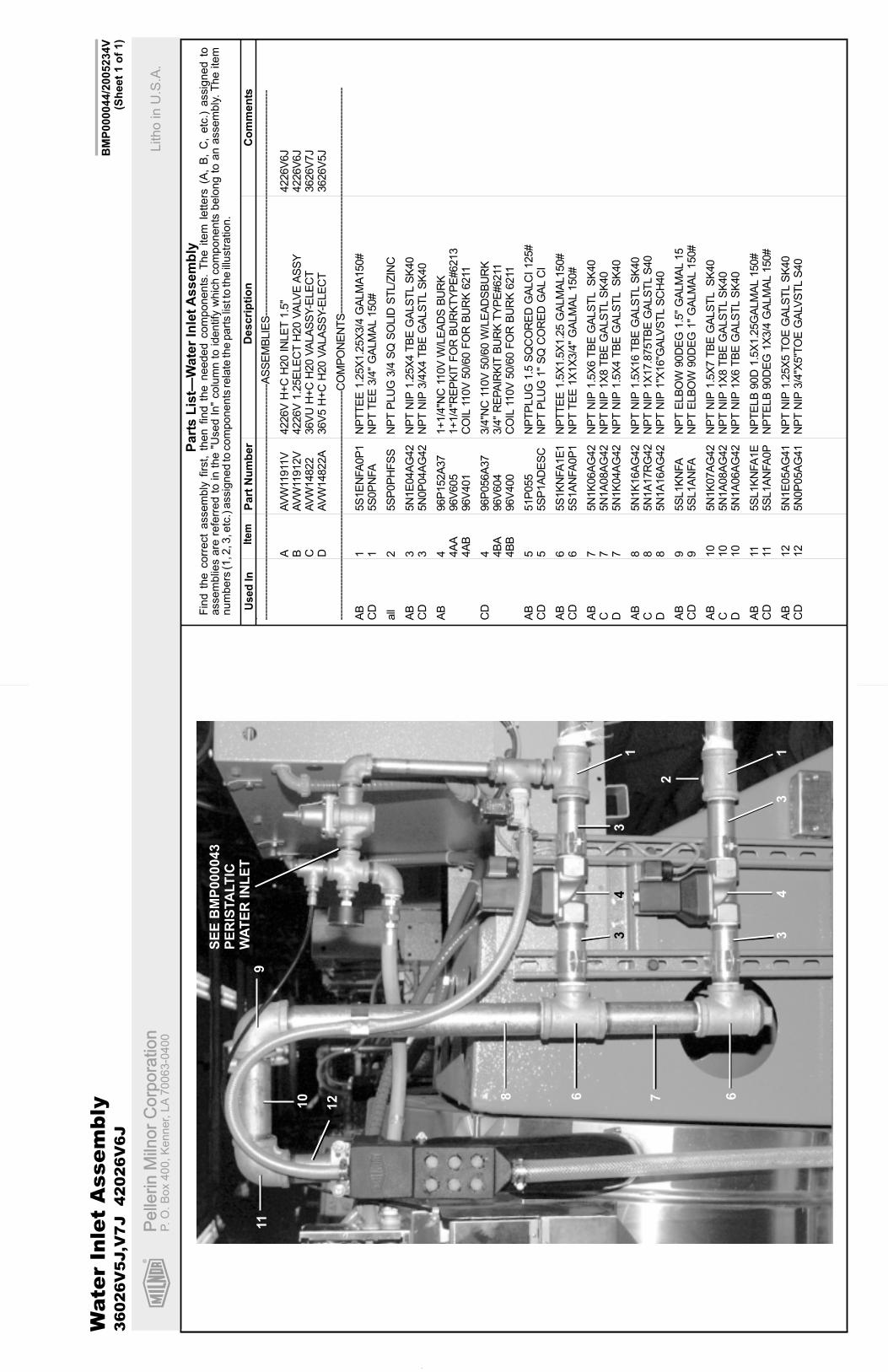
R
Pe
llerin
Miln
or
Co
rpo
ratio
nP
elle
rin
Miln
or
Co
rpo
ratio
nP.
O.
Bo
x4
00
,K
en
ne
r,L
A7
00
63
-04
00
Litho
inU
.S.A
.
Ite
mP
art
Nu
mb
er
Descri
pti
on
Co
mm
en
tsU
se
dIn
Fin
dth
ecorr
ect
assem
bly
firs
t,th
en
find
the
needed
com
ponents
.T
he
item
letters
(A,
B,
C,
etc
.)assig
ned
toassem
blie
sare
refe
rred
toin
the
"Used
In"
colu
mn
toid
entify
whic
hcom
ponents
belo
ng
toa
nassem
bly
.T
he
item
num
bers
(1,2
,3,e
tc.)
assig
ned
tocom
ponents
rela
teth
epart
slis
tto
the
illustr
ation.
Part
sL
ist—
Wate
rIn
let
Assem
bly
BM
P000044/2
005234V
(Sh
eet
1o
f1)
. ----
----
----
----
----
----
----
----
----
----
----
----
----
----
----
----
----
-AS
SE
MB
LIE
S--
----
----
----
----
----
----
----
----
----
----
----
----
----
----
----
----
AA
VW
11911
V4226V
H+
CH
20
INLE
T1.5
"4226V
6J
BA
VW
11912V
4226V
1.2
5E
LE
CT
H20
VA
LVE
AS
SY
4226V
6J
CA
VW
14822
36V
UH
+C
H20
VA
LA
SS
Y-E
LE
CT
3626V
7J
DA
VW
14822A
36V
5H
+C
H20
VA
LA
SS
Y-E
LE
CT
3626V
5J
----
----
----
----
----
----
----
----
----
----
----
----
----
----
----
----
---C
OM
PO
NE
NT
S--
----
----
----
----
----
----
----
----
----
----
----
----
----
----
----
----
AB
15S
1E
NFA
0P
1N
PT
TE
E1.2
5X
1.2
5X
3/4
GA
LM
A150#
CD
15S
0P
NFA
NP
TT
EE
3/4
"G
ALM
AL
150#
all
25S
P0P
HF
SS
NP
TP
LU
G3/4
SQ
SO
LID
ST
L/Z
INC
AB
35N
1E
04A
G42
NP
TN
IP1.2
5X
4T
BE
GA
LS
TL
SK
40
CD
35N
0P
04A
G42
NP
TN
IP3/4
X4
TB
EG
ALS
TL
SK
40
AB
496P
152A
37
1+
1/4
"NC
110V
W/L
EA
DS
BU
RK
4A
A96V
605
1+
1/4
"RE
PK
ITF
OR
BU
RK
TY
PE
#6213
4A
B96V
401
CO
IL11
0V
50/6
0F
OR
BU
RK
6211
CD
496P
056A
37
3/4
"NC
110V
50/6
0W
/LE
AD
SB
UR
K4B
A96V
604
3/4
"R
EP
AIR
KIT
BU
RK
TY
PE
#6211
4B
B96V
400
CO
IL11
0V
50/6
0F
OR
BU
RK
6211
AB
551P
055
NP
TP
LU
G1.5
SQ
CO
RE
DG
ALC
I125#
CD
55S
P1A
DE
SC
NP
TP
LU
G1"
SQ
CO
RE
DG
AL
CI
AB
65S
1K
NFA
1E
1N
PT
TE
E1.5
X1.5
X1.2
5G
ALM
AL150#
CD
65S
1A
NFA
0P
1N
PT
TE
E1X
1X
3/4
"G
ALM
AL
150#
AB
75N
1K
06A
G42
NP
TN
IP1.5
X6
TB
EG
ALS
TL
SK
40
C7
5N
1A
08A
G42
NP
TN
IP1X
8T
BE
GA
LS
TL
SK
40
D7
5N
1K
04A
G42
NP
TN
IP1.5
X4
TB
EG
ALS
TL
SK
40
AB
85N
1K
16A
G42
NP
TN
IP1.5
X16
TB
EG
ALS
TL
SK
40
C8
5N
1A
17R
G42
NP
TN
IP1X
17.8
75T
BE
GA
LS
TL
S40
D8
5N
1A
16A
G42
NP
TN
IP1"X
16"G
ALV
ST
LS
CH
40
AB
95S
L1K
NFA
NP
TE
LB
OW
90D
EG
1.5
"G
ALM
AL
15
CD
95S
L1A
NFA
NP
TE
LB
OW
90D
EG
1"
GA
LM
AL
150#
AB
10
5N
1K
07A
G42
NP
TN
IP1.5
X7
TB
EG
ALS
TL
SK
40
C10
5N
1A
08A
G42
NP
TN
IP1X
8T
BE
GA
LS
TL
SK
40
D10
5N
1A
06A
G42
NP
TN
IP1X
6T
BE
GA
LS
TL
SK
40
AB
115S
L1K
NFA
1E
NP
TE
LB
90D
1.5
X1.2
5G
ALM
AL
150#
CD
115S
L1A
NFA
0P
NP
TE
LB
90D
EG
1X
3/4
GA
LM
AL
150#
AB
12
5N
1E
05A
G41
NP
TN
IP1.2
5X
5T
OE
GA
LS
TL
SK
40
CD
12
5N
0P
05A
G41
NP
TN
IP3/4
"X5"T
OE
GA
LVS
TL
S40
Wate
rIn
let
Assem
bly
36026V
5J,V
7J
42026V
6J
11
2
333
3
44
668 7
10
911
12
SE
EB
MP
000043
PE
RIS
TA
LT
ICW
AT
ER
INL
ET

R
Pe
llerin
Miln
or
Co
rpo
ratio
nP
elle
rin
Miln
or
Co
rpo
ratio
nP.
O.
Bo
x4
00
,K
en
ne
r,L
A7
00
63
-04
00
Litho
inU
.S.A
.
BM
P010027/2
002064V
(Sh
eet
1o
f2)
Ste
am
Inle
tA
sse
mb
ly3
60
26
V5
J,V
7J
42
02
6V
6J
1
2
33
4,5
67
8
8
9

R
Pellerin Milnor CorporationPellerin Milnor CorporationP. O. Box 400, Kenner, LA 70063-0400
Litho in U.S.A.
Item Part Number Description CommentsUsed In
Find the correct assembly first, then find the needed components. The item letters (A, B, C, etc.) assigned toassemblies are referred to in the "Used In" column to identify which components belong to an assembly. The itemnumbers (1, 2, 3, etc.) assigned to components relate the parts list to the illustration.
Parts List—Steam Inlet Assembly
BMP010027/2002064V(Sheet 2 of 2)
.---------------------------------------------------------------------ASSEMBLIES------------------------------------------------------------------
none
-------------------------------------------------------------------COMPONENTS------------------------------------------------------------------
all 1 51T030 Y-STRAINER 3/4" CAST IRON
all 2 5SP0KGFSS NPT PLUG 1/2 SOSOLID GALSTL
all 3 5N0P03KF42 NPT NIP 3/4X3.5 TBE BLKSTLSK40
all 4 96P042A37 3/4"STEAMVAL 120V50/60 DINCOIL
all 5 96P042VA37 DIN CONNECTOR 120V 6FT LEADS
all 6 5SR0P0GMF NPT RED 3/4"X3/8" BLK 150#
all 7 53A025 MALECON.5X3/8COMP PH#68C-8-6
all 8 02 11967 TUBING=STEAM INLET 36QU 3626V5J,V7Jall 8 02 11966 TUBING=STEAM INLET 36 42QU 4226V6J
all 9 AVS14806 36V5J STEAM NOZZLE ASSY 3/4" 3626V5Jall 9 AVS14805 *STEAM NOZZLE ASSY 3/4" 3626V7J,4226V6J

R
Pe
llerin
Miln
or
Co
rpo
ratio
nP
elle
rin
Miln
or
Co
rpo
ratio
nP.
O.
Bo
x4
00
,K
en
ne
r,L
A7
00
63
-04
00
Litho
inU
.S.A
.
BM
P010014/2
002034V
(Sh
eet
1o
f2)
Dra
inV
alv
eIn
sta
llati
on
36
02
6V
5J,V
7J
42
02
6V
6J
1
2
34
5
6
7
8
(2P
LA
CE
S)
9,1
0
11
7 8

R
Pellerin Milnor CorporationPellerin Milnor CorporationP. O. Box 400, Kenner, LA 70063-0400
Litho in U.S.A.
Item Part Number Description CommentsUsed In
Find the correct assembly first, then find the needed components. The item letters (A, B, C, etc.) assigned toassemblies are referred to in the "Used In" column to identify which components belong to an assembly. The itemnumbers (1, 2, 3, etc.) assigned to components relate the parts list to the illustration.
Parts List—Drain Valve Installation
BMP010014/2002034V(Sheet 2 of 2)
.---------------------------------------------------------------------ASSEMBLIES------------------------------------------------------------------
none
-------------------------------------------------------------------COMPONENTS------------------------------------------------------------------
all 1 W2 03974A *WLMT=3022F8 RIGID DRAIN PIPE
all 2 02 03412 BRKT=DEPEND-O DUMPVAL MTG
all 3 60B075 DFW56-33PMSP RUBB CONN.
all 4 96D350A37 DRINVAL 3"N/O MTRDR120V 50/60C
all 5 60E303C HOSE 3"ID DAYCO #7216-3002
all 6 27A075A T-BOLT HOSECLAMP 3.03"T03.34"
all 7 60E303W HOSE 3"ID DRAIN-PLICORD 125
all 8 27A077A T-BOLT HOSECLAMP 3.37-3.68"SS
all 9 15G198 HXFLGNUT 3/8-16 ZINC
all 10 15K092 HEXFLGSCR 3/8-16X1 GR8 CS
all 11 15P200 TRDCUT-F HXWASHD 3/8-16X3/4NIK

R
Pe
llerin
Miln
or
Co
rpo
ratio
nP
elle
rin
Miln
or
Co
rpo
ratio
nP.
O.
Bo
x4
00
,K
en
ne
r,L
A7
00
63
-04
00
Litho
inU
.S.A
.
BM
P920017/2
002044V
(Sh
eet
1o
f2)
3”
Ele
ctric
Dra
inV
alv
e
SP
RIN
G
MA
IND
RIV
E
PIN
KIT
ME
TA
LW
AS
HE
R
BE
AR
ING
"V"
PA
CK
ER
SE
AL
MO
TO
RM
OU
NT
ING
PLA
TE
14
3M
OT
OR
CO
VE
R
VA
LV
EB
OD
Y
AS
SE
MB
LY
2
*
*
*
**
*

R
Pellerin Milnor CorporationPellerin Milnor CorporationP. O. Box 400, Kenner, LA 70063-0400
Litho in U.S.A.
Item Part Number Description CommentsUsed In
Find the correct assembly first, then find the needed components. The item letters (A, B, C, etc.) assigned toassemblies are referred to in the "Used In" column to identify which components belong to an assembly. The itemnumbers (1, 2, 3, etc.) assigned to components relate the parts list to the illustration.
Parts List—3” Electric Drain Valve
BMP920017/2002044V(Sheet 2 of 2)
.
---------------------------------------------------------------------ASSEMBLIES------------------------------------------------------------------
A 96D350A37 DRINVAL 3"N/O MTRDR120V 50/60CB 96D350A71 DRINVAL 3"N/O MTRDR240V 50/60C
-------------------------------------------------------------------COMPONENTS------------------------------------------------------------------A 1 96D35MTR37 120V 50/60CMTR FOR 3"DRAINVALB 1 96D35MTR71 240V 50/60CMTR FOR 3"DRAINVAL
all 2 96D35B0D B0DY & BALL FOR 3" DRAIN VALVE
all 3 96D35C0V MTRCOVER 2-PCFOR 3"DRAINVAL
all 4 96D35PIN DRIVE PIN KIT FOR 3" DRAIN VAL