service flow mapping to mpls-vpn on the cisco …...ciscoiosrelease12.2(33)scd andlater...
TRANSCRIPT

Service Flow Mapping to MPLS-VPN on the CiscoCMTS
First Published: February 14, 2008Last Updated: July 11, 2012
This document describes the Service Flow Mapping to MPLS-VPN feature, which enhances the existingmultiprotocol label switching (MPLS) VPNs support to provide more flexible managed access for multipleISP support over a hybrid fiber-coaxial (HFC) cable network.
Cisco IOS Release 12.2(33)SCA integrates support for this feature on the Cisco CMTS routers. Thisfeature is also supported in Cisco IOS Release 12.3BC, and this document contains information thatreferences many legacy documents related to Cisco IOS 12.3BC. In general, any references to Cisco IOSRelease 12.3BC also apply to Cisco IOS Release 12.2SC.
Note
Finding Feature Information
Your software release may not support all the features documented in this module. For the latest featureinformation and caveats, see the release notes for your platform and software release. To find informationabout the features documented in this module, and to see a list of the releases in which each feature issupported, see the Feature Information Table at the end of this document.
Use Cisco Feature Navigator to find information about platform support and Cisco software image support.To access Cisco Feature Navigator, go to http://tools.cisco.com/ITDIT/CFN/. An account on http://www.cisco.com/ is not required.
Contents
• Prerequisites for Mapping Service Flows to MPLS-VPN, page 2
• Restrictions for Mapping Service Flows to MPLS-VPN, page 4
• Information About Mapping Service Flows to MPLS-VPN, page 4
• How to Configure the Service Flow Mapping to MPLS-VPN feature, page 7
• Monitoring and Maintaining Examples for Service Flow Mapping to MPLS-VPN Feature , page 13
• Configuration Examples, page 18
• Additional References, page 22
Cisco CMTS Router Layer 2 and VPN Features Configuration Guide OL-27608-01 1

• Feature Information for Service Flow Mapping to MPLS-VPN on the Cisco CMTS Routers, page 25
Prerequisites for Mapping Service Flows to MPLS-VPN• To support static service-flow to MPLS-VPN functionality, the Cisco uBR7200 series routers must berunning Cisco IOS Release 12.2(11)BC2 or later releases and the Cisco uBR10000 series routers mustbe running Cisco IOS Release 12.3(13)BC or later releases.
• To support dynamic service-flow toMPLS-VPN functionality, the Cisco CMTS routers must be runningCisco IOS Release 12.3(13)BC or later releases.
• All Cisco CMTSes must be configured for the proper virtual routing and forwarding (VRF) interfaces,as specified by the documentation in the Additional References, on page 22.
• To support static service-flow to MPLS VPN mapping, the DOCSIS configuration file editor mustsupport the inclusion of Vendor-specific Options (TLV subtype 43) in the Upstream Service FlowEncodings parameter set (TLV type 24). The new option to be added is called the VPN RouteDistinguisher (RD) parameter (TLV subtype 4) and must be preceded by the Cisco Vendor ID (00000C).
For example, using the Cisco DOCSIS Configurator tool, you would specify the following fields in the ASCIIconfiguration file:
24 (Upstream Service Flow Block)S43 (Vendor Specific Options)T08 (Vendor ID) = 00 00 0cT04 (VPN Route Distinguisher) = xx xx xx xx xx xx xx xx
where the VPN RD contains eight hexadecimal bytes. The first two hexadecimal bytes specify the format ofthe remaining six bytes:
• If bytes 1 and 2 are 00 00, bytes 3 and 4 specify the 16-bit autonomous system (AS) number, andbytes 5 to 8 specify a unique 32-bit identifier.
◦
◦If bytes 1 and 2 are 00 01, bytes 3 to 6 specify the 32-bit IP address, and bytes 7 and 8 specify aunique 16-bit identifier.
Configure the VPN RD parameter to the same route-distinguisher ID that you have specified on the CiscoCMTS using the rd command in VRF configuration submode.
• To support DOCSIS configuration file-based dynamic service-flow toMPLSVPNmapping, the DOCSISconfiguration file editor must support the inclusion of the Cisco Vendor-specific Dynamic Flow VPNRD parameter (TLV subtype 13).
For example, using the Cisco DOCSIS Configurator tool, you would specify the following fields in the ASCIIconfiguration file:
43 (Vendor Specific Info)S8 (Vendor ID) = 0-0-cS13 (Dynamic Flow VPN RD) = xx xx xx xx xx xx xx xx
where the eight-byte VPN RD uses the same format as specified above.
The table shows the Cisco CMTS hardware compatibility prerequisites for this feature.
Cisco CMTS Router Layer 2 and VPN Features Configuration Guide2 OL-27608-01
Service Flow Mapping to MPLS-VPN on the Cisco CMTSPrerequisites for Mapping Service Flows to MPLS-VPN

The hardware components introduced in a given Cisco IOS Release will be supported in all subsequentreleases unless otherwise specified.
Note
Table 1: Service Flow Mapping to MPLS-VPN Hardware Compatibility Matrix
Cable Interface CardsProcessor EngineCMTS Platform
Cisco IOS Release 12.2(33)SCBand later
• Cisco uBR10-MC5X20U/H
Cisco IOS Release 12.2(33)SCCand later
• Cisco UBR-MC20X20V
Cisco IOS Release 12.2(33)SCEand later
• Cisco uBR-MC3GX60V 1
Cisco IOS Release 12.2(33)SCAand later
• PRE2
Cisco IOS Release 12.2(33)SCBand later
• PRE4
Cisco IOS Release 12.2(33)SCHand later
• PRE5
Cisco uBR10012 UniversalBroadband Router
Cisco IOS Release 12.2(33)SCAand later
• Cisco uBR-MC28U/X
Cisco IOS Release 12.2(33)SCDand later
• Cisco uBR-MC88V 2
Cisco IOS Release 12.2(33)SCAand later
• NPE-G1
• NPE-G2
Cisco uBR7246VXR UniversalBroadband Router
Cisco IOS Release 12.2(33)SCAand later
• Cisco uBR-E-28U
• Cisco uBR-E-16U
• Cisco uBR-MC28U/X
Cisco IOS Release 12.2(33)SCDand later
• Cisco uBR-MC88V
Cisco IOS Release 12.2(33)SCAand later
• NPE-G1
Cisco IOS Release 12.2(33)SCBand later
• NPE-G2
Cisco uBR7225VXR UniversalBroadband Router
1 The Cisco uBR-3GX60V cable interface line card is not compatible with PRE2.2 The Cisco uBR-MC88V cable interface line card is compatible only with NPE-G2.
Cisco CMTS Router Layer 2 and VPN Features Configuration Guide OL-27608-01 3
Service Flow Mapping to MPLS-VPN on the Cisco CMTSPrerequisites for Mapping Service Flows to MPLS-VPN

The combination of a PRE4 and Cisco Half-Height Gigabit Ethernet (HHGE) is not supported in the samechassis.
Note
Restrictions for Mapping Service Flows to MPLS-VPN• Cable modems using this feature should use a unique DOCSIS configuration file that creates an upstreampacket classifier and service flow corresponding to each customer premises equipment (CPE) or mediaterminal adapter (MTA) device that needs to have its traffic routed to a different MPLS VPN than tothe one the cable modem natively belongs.
• The DOCSIS configuration file for a cable modem must be updated whenever a CPE device that needsto use a different MPLS VPN than the cable modem’s native MPLS VPN is added or removed, orwhenever the MAC address for a CPE device changes. The cable modem must also be reset to executethe changes in the DOCSIS configuration file.
• By default, dynamically generated upstream service flows use theMPLSVPNwith which a cable modemis natively associated. In order to specify a different MPLS VPN for use by dynamically generatedupstream service flows, it is necessary to do one of the following:
◦Specify an RD in the Cisco Vendor-specific Info Subtype Option 13 within the cable modem’sDOCSIS configuration file.
◦Use the global or cable interface command cable dynamic-flow vrf to specify an MPLS VPNname.
Information About Mapping Service Flows to MPLS-VPNThe Service Flow Mapping to MPLS-VPN feature provides the following benefits to cable service providersand their partners and customers:
• Allows the service provider to maintain full control over the cable modems and other devices that aredirectly connected to the cable plant.
• Provides a highly flexible, scalable, and easy to manage system.
• Supports overlapping IP address ranges.
• Provides secure support for multiple intranets and extranets.
• Supports multiple IP Quality of Service (QoS) classes.
• Enables the Cisco CMTS router to support the mapping of dynamic service flows to an MPLS VPN byusing the cable dynamic-flow vrf command, or the Dynamic Flow VPN RD parameter (CiscoVendor-specific Info Subtype 13) in a DOCSIS configuration file.
The Cisco CMTS routers provide managed access by means of MPLS VPNs configured over cablesubinterfaces, with each subinterface configured for a specific ISP and each cable modem associating itselfand all connected CPE to a specific subinterface. This use ofMPLSVPNs gives service providers a manageableway to offer users access to multiple ISPs over the same physical HFC cable network.
Cisco CMTS Router Layer 2 and VPN Features Configuration Guide4 OL-27608-01
Service Flow Mapping to MPLS-VPN on the Cisco CMTSRestrictions for Mapping Service Flows to MPLS-VPN

This system works very well when all CPE devices behind a cable modem are using the same ISP. However,users are increasingly requesting more complex networks that would allow multiple CPE devices to accessdifferent ISPs through the same cable modem. For example, different users in one household might want touse different PCs to access different ISPs. Another increasingly common situation is that one user requires asecure VPN connection for telecommuting through one ISP, while other users in the household use othercomputers to access the public Internet through a separate ISP.
As another example, a service provider offering a PacketCable voice-over-IP (VoIP) service may wish toallow one ISP to manage and operate the voice component of the cable network, and another to manage andoperate the data component.
The Service FlowMapping toMPLS-VPN feature solves this problem by using DOCSIS 1.1 upstream packetclassifiers and service flow IDs (SFIDs) to map individual CPE devices to separate MPLS-VPN interfaces.The SFID to MPLS-VPN mapping occurs as follows:
1 The service provider creates for each cable modem a DOCSIS configuration file that contains the followinginformation:
• Secondary upstream service flows that specify QoS profiles for CPE devices that must be associatedwith a particular MPLS VPN where that MPLS VPN is different from the cable modem’s nativeMPLS VPN assignment.
• For each upstream service flow, a Vendor-specific QoS Parameter (TLV type 43, subtype 04) thatidentifies the MPLS VPN RD for packets using this particular service flow.
• Upstream packet classifiers that correspond to the secondary upstream service flows, so that thecable modemmay direct packets from the CPE in question to the correct service flows. To accomplishthis, each classifier must contain the MAC address of CPE that are to be associated with the serviceflow and consequently with the MPLS VPN. This would typically be accomplished by making useof the Source MAC Address parameter (TLV type 10, subtype 2).
The DOCSIS configuration file also must create a primary downstream (DS) and a primary upstream (US)service flow and packet classifier, as well as other required parameters, but these are not used for the SFIDto MPLS-VPN mapping.
Note
2 The cable modem downloads the DOCSIS configuration file during its registration process and configuresitself for the proper service flows and packet classifiers.
3 The cable modem then comes online, at which point it begins receiving packets from its CPE devices. Thecable modem uses the packet’s source MAC address to match the packet to the proper packet classifier,which then identifies the correct SFID to use. The cable modem then transmits the packet to the CiscoCMTS using this upstream SFID.
4 The Cisco CMTS examines the packet to determine its SFID, and then uses the Vendor-specific QoSParameter associated with that service flow to route the packet to the appropriate MPLS-VPN interface.
5 When a dynamic upstream service flow is generated, as in the case with a PacketCable VoIP phone call,the Cisco CMTS determines the MPLS VPN to associate the new upstream service flow by one of severalmethods in the following order of precedence:
a If the cable modem’s DOCSIS configuration file contains the Dynamic FlowVPNRD parameter (CiscoVendor-specific Info Subtype 13), then the dynamic service flow’s VPN is set to the one using the RDas specified in the parameter.
b If the cable interface on which the modem is online has had the cable dynamic-flow vrf commandapplied, then the dynamic service flow’s VPN is set to the MPLS VPN specified by that command.
Cisco CMTS Router Layer 2 and VPN Features Configuration Guide OL-27608-01 5
Service Flow Mapping to MPLS-VPN on the Cisco CMTSInformation About Mapping Service Flows to MPLS-VPN

c If the global cable dynamic-flow vrf command is applied, then the dynamic service flow’s VPN isset to the MPLS VPN specified by this command.
d Finally, the dynamic service flow’s VPN is set to the VPN to which the cable modem is associated.
If the DOCSIS configuration file for the cable modem does not contain an MPLS-VPN route, the packetsfrom that cable modem are routed according to the routing tables on the Cisco CMTS.
MPLS QoS via TLV for non-L2VPN Service FlowTheMPLS QoS via TLV for non-L2VPN Service Flow feature is a QoS enhancement based onMPLS TrafficClass (TC) bits for MPLS L3VPN. This feature is introduced in Cisco IOS Release 12.2(33)SCG to mark TCbits for MPLS L3VPN imposition packets and classify DS packets based on TC bits of MPLS dispositionpackets, using vendor-specific TLVs.
The MPLS TC bits were previously known as MPLS EXP bits. RFC 5462 has renamed the MPLS EXP fieldto MPLS TC field.
VoIP SFID MappingThe introduction of WB MTAs and the resequencing delays with the DS bonded traffic are pushing voicetraffic towards non-bonded channels.
Starting with Cisco IOS Release 12.2(33)SCB, as the WB MTA uses the cable interface line card (CLC) DSinterface as the primary interface, it can also protect voice traffic from edge quadrature amplitude modulation(e-QAM) and shared port adapter (SPA) failures. It also helps in leveraging the CLC redundancy feature toprotect voice calls.
The VoIP Service Flow ID (SFID)Mapping feature leverages Data-over-Cable Service Interface Specifications(DOCSIS) 3.0 Service Flow (SF) Attribute-based assignment, which allows forwarding to Bonding groupsor to single channel on a per-SF basis.
The CPE constructs DSX (Dynamic-service DOCSIS mac-management) messages that does not conform toDOCSIS 3.0 specifications and does not includes the SF Attribute parameters. However, the Cisco CMTSshould control these factors and whenever voice calls are initiated; the Cisco CMTS must add SF Attributes,configured by the user, to the DSX messages.
Prerequisites for VOIP SFID Mapping• DOCSIS 3.0-compatible voice CPE and DOCSIS 3.0-compatible PacketCable specifications.
• The Required Attribute Mask and Forbidden Attribute Mask should be configured globally.
• Mask values above zero must be inserted to all dynamic voice DS requests from WB CMs.
• The SF assignment must follow the mask values inserted in DSX message to determine forwarding.
• The Type-Length-Values (TLVs) inserted at the Required Attribute Mask and Forbidden Attribute Maskshould not be sent back. They are not supported while sending Dynamic Service Response (DSx-RSP)through embedded media terminal adapter (eMTA) and could lead to cable modem (CM) error.
Cisco CMTS Router Layer 2 and VPN Features Configuration Guide6 OL-27608-01
Service Flow Mapping to MPLS-VPN on the Cisco CMTSMPLS QoS via TLV for non-L2VPN Service Flow

Restrictions for VOIP SFID Mapping• TheVoIP SFIDMapping feature is supported only on the Cisco uBR10012Universal Broadband Router.
• DS SF Attribute TLVs inserted by the Cisco CMTS are skipped from TLV encoding.
How to Configure the Service Flow Mapping to MPLS-VPNfeature
The following section provides information on how to configure the Service Flow Mapping to MPLS-VPNfeature. Each task in the list is identified as either required or optional.
This section describes only the configuration tasks needed to enable the Service Flow Mapping toMPLS-VPN feature. It does not describe the basic MPLS-VPN configuration tasks. For information onconfiguring MPLS-VPN routes, see the documentation listed in the Additional References, on page 22.
Note
Creating a DOCSIS Configuration FileThe Cisco CMTS automatically maps service flows to MPLS-VPN interfaces when an upstream service flowincludes the VPN RD parameter as a vendor-specific TLV. The VPN RD parameter points to theroute-distinguisher ID that has been specified using the rd command in VRF configuration submode.
You must create a corresponding upstream packet classifier that identifies the source MAC address that willuse this SFID-to-MPLS VPN mapping. To create a DOCSIS configuration file that contains both of theseparameters, use the following procedure.
This procedure uses the CiscoDOCSISConfigurator tool to create the DOCSIS configuration file. However,you can use any tool that creates DOCSIS-compatible configuration files.
Note
For information about the rd command, see the command reference.Note
Step 1 Obtain the MAC addresses for the CPE devices that must be associated with a different MPLS VPN than the cablemodem’s native MPLS VPN association.
Step 2 Create an upstream packet classifier for each CPE device, specifying the service flow reference of the appropriateupstream service flow and the sourceMAC address of the CPE, along with the other appropriate parameters. For example,the following configuration for classifier 14 specifies that the service flow with service flow reference 7 should be usedfor the MAC address at 00 00 0C A1 B2 C3:
Example:
22 (Upstream Packet Classification Encoding Block)
Cisco CMTS Router Layer 2 and VPN Features Configuration Guide OL-27608-01 7
Service Flow Mapping to MPLS-VPN on the Cisco CMTSHow to Configure the Service Flow Mapping to MPLS-VPN feature

S01 (Classifier Reference) = 14S03 (Service Flow Reference) = 7S10 (Ethernet LLC Packet Classification Encodings)
T02 (Source MAC Address) = 00 00 0C A1 B2 C3
Step 3 Create a matching upstream service flow for this CPE device. This service flow must include all necessary parameters,as well as a vendor-specific VPN RD parameter (TLV subtype 4) that identifies the route-distinguisher ID for the VRFroute that has been created for this user.The route-distinguisher ID consists of two integers that can be in the following two forms:
• Type 0—Contains a 16-bit autonomous system (AS) number and a unique 32-bit identifier.
• Type 1—Contains a 32-bit IP address and a unique 16-bit identifier.
Configure the VPN RD parameter to the same route-distinguisher ID that you have specified on the Cisco CMTS usingthe rd command in VRF configuration submode. For example, if you configured a type 0 route using the following CLIcommands:
Example:
ip vrf isp1rd 64000:1
Configure the matching upstream service flow with the following parameters:
Example:
24 (Upstream Service Flow Encodings)S43 (Vendor Specific Options) = 8.3.0.0.12.4.8.0.0.250.0.0.0.0.1
The Vendor-specific Options field translates into two TLVs. The first TLV is of type 8 (Vendor ID), length 3, and valueof 00.00.0C hexadecimal to identify Cisco Systems. The second TLV is of type 4 (VPN RD), length 8, and value of00.00.FA.0.0.0.0.1 (hexadecimal).
If you are using the graphical interface in the Cisco DOCSIS Configurator tool to create the DOCSIS configurationfile, enter the entire dotted decimal string into the “Vendor Specific QoS” field in the Upstream and DownstreamService Flow screens. Using the above example, you would enter “8.3.0.0.12.4.8.0.0.0.250.0.0.0.1” into this field.
Tip
Similarly, if you configured a type 1 route using the following CLI commands:
Example:
ip vrf isp2rd 10.10.10.15:1
Configure the matching upstream service flow with the following parameters:
Example:
24 (Upstream Service Flow Encodings)S43 (Vendor Specific Options) = 8.3.0.0.12.4.8.0.1.10.10.10.15.0.1
Similarly, the Vendor-specific Options field translates into two TLVs. The first TLV is of type 8 (Vendor ID), length 3,and value of 00.00.0C hexadecimal to identify Cisco Systems. The second TLV is of type 4 (VPN RD), length 8, andvalue of 00.01.0A.0A.0A.0F.00.01 (hexadecimal).
Cisco CMTS Router Layer 2 and VPN Features Configuration Guide8 OL-27608-01
Service Flow Mapping to MPLS-VPN on the Cisco CMTSCreating a DOCSIS Configuration File

Step 4 Repeat this procedure for each upstream packet classifier and service flow that is to be mapped to anMPLS-VPN interface.
Mapping Dynamic Service FlowsIf theMPLS VPN to which dynamic service flows are mapped must be set on a per-cable-modem basis, ratherthan on a per-cable-interface or per-Cisco-CMTS basis, then the Dynamic Flow VPN RD parameter (CiscoVendor-specific Info Subtype 13) must be added to the DOCSIS configuration. The Dynamic Flow VPN RDparameter is used to specify the route-distinguisher ID for the VRF route that has been created for use bydynamic service flows.
In general, the MPLS VPN to which dynamic service flows must be mapped should be the same MPLSVPN as specified for static service-flow to MPLS VPN mapping.
Note
Step 1 Refer to Step 3 of Creating a DOCSIS Configuration File, on page 7.Step 2 Configure the VPN RD parameter to the same route-distinguisher ID that you have specified on the Cisco CMTS by
means of the rd command in VRF configuration submode. For example, if you configured a type 0 route by means ofthe following CLI commands:
Example:ip vrf isp1rd 64000:1
Configure the matching Dynamic Flow VPN RD parameter as follows:
Example:43 (Vendor Specific Info)
S8 (Vendor ID) = 0-0-cS13 (Dynamic Flow VPN RD) = 0-0-fa-0-0-0-0-1
The Vendor-specific Options field translates into two TLVs:
• The first TLV is of type 8 (Vendor ID), length 3, and value of 00.00.0C (hexadecimal), to identify Cisco Systems.
• The second TLV is of type 4 (VPN RD), length 8, and value of 00.00.FA.0.0.0.0.1 (hexadecimal).
Similarly, if you configured a type 1 route by means of the following CLI commands:
Example:ip vrf isp2rd 10.10.10.15:1
Configure the matching upstream service flow with the following parameters:
Cisco CMTS Router Layer 2 and VPN Features Configuration Guide OL-27608-01 9
Service Flow Mapping to MPLS-VPN on the Cisco CMTSMapping Dynamic Service Flows

Example:43 (Vendor Specific Info)
S8 (Vendor ID) = 0-0-cS13 (Dynamic Flow VPN RD) = 0-1-a-a-a-f-0-1
Similarly, the Vendor-specific Options field translates into two TLVs:
• The first TLV is of type 8 (Vendor ID), length 3, and value of 00.00.0C (hexadecimal) to identify Cisco Systems.
• The second TLV is of type 4 (VPN RD), length 8, and value of 00.01.0A.0A.0A.0F.00.01 (hexadecimal).
The per-cable-modem Dynamic Flow VPN RD parameter takes precedence over any per-cable-interface orper-Cisco-CMTS dynamic service flow to MPLS VPN configuration.
Step 3 If the MPLS VPN to which dynamic service flows are mapped must be set on a per-cable-interface basis, as opposed toper cable modem or per-Cisco-CMTS, then use the following the cable interface configuration command:
Example:Router# interface cablex/y/zRouter(config-if)# cable dynamic-flow vrfvrf-name
For example, if you configured the following VRF for use with dynamically generated service flows:
Example:ip vrf isp1rd 64000:1
Then you could use the following per-cable-interface command to ensure that dynamic service flows are mapped:
Example:Router# interface cablex/y/zRouter(config-if)# cable dynamic-flow vrfisp1
The per-cable-interface dynamic service flow to MPLS VPN configuration takes precedence over the globalper-Cisco-CMTS dynamic service flow to MPLS VPN configuration, but not over the per-cable-modem Dynamic FlowVPN RD parameter.
Step 4 If the MPLS VPN to which dynamic service flows are mapped must be set on a per-Cisco-CMTS basis, as opposed toper cable modem or per cable interface, then use the global configuration command:
Example:Router# cable dynamic-flow vrfvrf-name
For example, if you configured the following VRF for use with dynamically generated service flows:
Cisco CMTS Router Layer 2 and VPN Features Configuration Guide10 OL-27608-01
Service Flow Mapping to MPLS-VPN on the Cisco CMTSMapping Dynamic Service Flows

Example:ip vrf isp2rd 10.10.10.15:1
Then you could use the following per-cable-interface command to ensure that dynamic service flows are mapped:
Example:Router# interface cablex/y/zRouter(config-if)# cable dynamic-flow vrfisp2
Configuring MPLS QoS via TLV for non-L2VPN Service Flow
This feature is configured using a cable modem configuration file and is dependent on the generalconfiguration of the L3VPN.
Note
This section describes how to configure traffic class bits for MPLS imposition and disposition packets andon how to use vendor-specific TLVs with AToM L2VPN and MPLS L3VPN.
Restrictions for Configuring MPLS QoS via TLV• This feature supports only PRE4. It will not support PRE2.
• This feature supports only IPv4. It will not support IPv6.
• This feature supports only Cisco uBR10012 routers. The Cisco uBR7200 series routers is not supported.
• This feature does not support SNMP.
• This feature does not support dynamic service flows.
• Only up to four VPNs and eight upstream service flows per CM can be configured.
• For a VPN, only a maximum of eight DS classifiers (using TC bits in the range from 0 to 7) can beconfigured.
• If TC bits downstream classifiers are configured for a VPN, then the downstreamMPLS packets belongingto the VPN are processed only on TC bits classification. It will not process general IP header fieldclassification.
Cisco CMTS Router Layer 2 and VPN Features Configuration Guide OL-27608-01 11
Service Flow Mapping to MPLS-VPN on the Cisco CMTSConfiguring MPLS QoS via TLV for non-L2VPN Service Flow
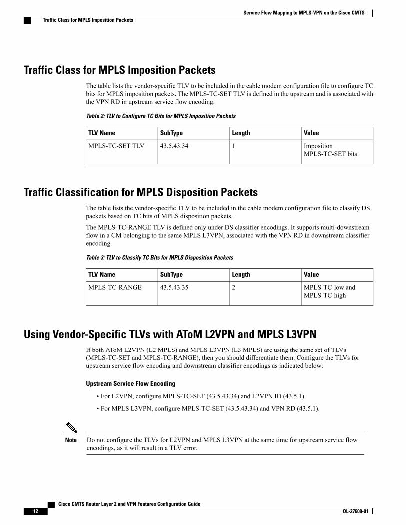
Traffic Class for MPLS Imposition PacketsThe table lists the vendor-specific TLV to be included in the cable modem configuration file to configure TCbits for MPLS imposition packets. The MPLS-TC-SET TLV is defined in the upstream and is associated withthe VPN RD in upstream service flow encoding.
Table 2: TLV to Configure TC Bits for MPLS Imposition Packets
ValueLengthSubTypeTLV Name
ImpositionMPLS-TC-SET bits
143.5.43.34MPLS-TC-SET TLV
Traffic Classification for MPLS Disposition PacketsThe table lists the vendor-specific TLV to be included in the cable modem configuration file to classify DSpackets based on TC bits of MPLS disposition packets.
The MPLS-TC-RANGE TLV is defined only under DS classifier encodings. It supports multi-downstreamflow in a CM belonging to the same MPLS L3VPN, associated with the VPN RD in downstream classifierencoding.
Table 3: TLV to Classify TC Bits for MPLS Disposition Packets
ValueLengthSubTypeTLV Name
MPLS-TC-low andMPLS-TC-high
243.5.43.35MPLS-TC-RANGE
Using Vendor-Specific TLVs with AToM L2VPN and MPLS L3VPNIf both AToM L2VPN (L2 MPLS) and MPLS L3VPN (L3 MPLS) are using the same set of TLVs(MPLS-TC-SET and MPLS-TC-RANGE), then you should differentiate them. Configure the TLVs forupstream service flow encoding and downstream classifier encodings as indicated below:
Upstream Service Flow Encoding
• For L2VPN, configure MPLS-TC-SET (43.5.43.34) and L2VPN ID (43.5.1).
• For MPLS L3VPN, configure MPLS-TC-SET (43.5.43.34) and VPN RD (43.5.1).
Do not configure the TLVs for L2VPN and MPLS L3VPN at the same time for upstream service flowencodings, as it will result in a TLV error.
Note
Cisco CMTS Router Layer 2 and VPN Features Configuration Guide12 OL-27608-01
Service Flow Mapping to MPLS-VPN on the Cisco CMTSTraffic Class for MPLS Imposition Packets

Downstream Classifier Encoding
• L2VPN—Configure MPLS-TC-RANGE (43.5.43.35) and L2VPN ID (43.5.1).
• MPLS L3VPN—Configure MPLS-TC-RANGE (43.5.43.35) and VPN RD (43.5.1).
Monitoring and Maintaining Examples for Service FlowMapping to MPLS-VPN Feature
This section provides examples of the commands that show the configuration and current status of the cablemodems (CMs) that are using the Service Flow Mapping to MPLS-VPN feature. These examples display anumber of CMs that are online, and the last CM (with the primary service identifier [SID] of 6) has three CPEdevices connected to separate ISPs.
Displaying CMs and CPE devicesTo display the number of CMs that are currently registered and online, use the show cable modem command:
Router# show cable modem
MAC Address IP Address I/F MAC Prim RxPwr Timing Num BPIState Sid (db) Offset CPE Enb
0030.8047.b41f 5.108.1.21 C3/0/U2 online(pt) 1 0.75 2821 0 Y0007.0e03.1349 5.109.1.9 C3/0/U0 online 2 *0.00 2816 0 N0007.0e03.12bd 5.108.1.18 C3/0/U0 online(pt) 3 -0.25 2812 0 Y0030.80bc.22d5 5.108.1.20 C3/0/U0 online(pt) 4 0.25 2819 0 Y0007.0e03.1331 5.111.1.6 C3/0/U0 online 5 -0.25 2816 0 N00a0.73b0.4cc1 5.110.1.6 C3/0/U0 online(pt) 6 -0.25 2990 3 Y
To display the CPE devices that are associated with each CM, use the show interface cablemodem command:
Router# show interface cable 3/0 modem 0
SID Priv bits Type State IP address method MAC address1 11 modem up 5.108.1.21 dhcp 0030.8047.b41f2 00 modem up 5.109.1.9 dhcp 0007.0e03.13493 11 modem up 5.108.1.18 dhcp 0007.0e03.12bd4 11 modem up 5.108.1.20 dhcp 0030.80bc.22d55 00 modem up 5.111.1.6 dhcp 0007.0e03.13316 11 modem up 5.110.1.6 dhcp 00a0.73b0.4cc16 11 host unknown 131.1.2.30 dhcp 0002.e323.ac086 11 host unknown 129.1.2.18 dhcp 0050.046b.8b976 11 host unknown 130.1.2.24 dhcp 0050.da80.c13e
To display the MPLS VPN RD to be used by dynamic service flows from a cable modem using the DynamicFlow VPN RD parameter (Cisco Vendor-specific Info Subtype 13), use the show cable modem verbosecommand:
Router# show cable modem 0007.0e02.afa5 verboseMAC Address : 00a0.73b0.4cc1IP Address : 5.110.1.6Prim Sid : 6Interface : C3/0/U0sysDescr :Upstream Power : 0.00 dBmV (SNR = 33.83 dB)Downstream Power : 0.00 dBmV (SNR = ----- dB)Timing Offset : 2290Initial Timing Offset : 2290Received Power : 0.00 dBmV
Cisco CMTS Router Layer 2 and VPN Features Configuration Guide OL-27608-01 13
Service Flow Mapping to MPLS-VPN on the Cisco CMTSMonitoring and Maintaining Examples for Service Flow Mapping to MPLS-VPN Feature

MAC Version : DOC1.1QoS Provisioned Mode : DOC1.1Enable DOCSIS2.0 Mode : YPhy Operating Mode : tdmaCapabilities : {Frag=Y, Concat=Y, PHS=Y, Priv=BPI+}Sid/Said Limit : {Max US Sids=4, Max DS Saids=0}Optional Filtering Support : {802.1P=N, 802.1Q=N}Transmit Equalizer Support : {Taps/Symbol= 1, Num of Taps= 8}Number of CPE IPs : 0(Max CPE IPs = 16)CFG Max-CPE : 5Flaps : 0()Errors : 0 CRCs, 0 HCSesStn Mtn Failures : 0 aborts, 0 exhaustedTotal US Flows : 1(1 active)Total DS Flows : 1(1 active)Total US Data : 1606 packets, 129106 bytesTotal US Throughput : 43 bits/sec, 0 packets/secTotal DS Data : 28 packets, 1792 bytesTotal DS Throughput : 0 bits/sec, 0 packets/secActive Classifiers : 0 (Max = NO LIMIT)DSA/DSX messages : permit allDynamic Secret : 4E7AD0AEA48F94DE0EB773494B57EA74Dynamic flows mapped to VPN RD : 64000:1
! The dynamic mapping is listed above.Total Time Online : 1d3h
Displaying SID and MPLS MappingsTo display the mapping of currently used SIDs to SFIDs and their current state, use the show interface cablesid verbose command:
Router# show interface cable 3/0 sid verbose
Sid Prim MAC Address IP Address Type Age Admin Sched SfidState Type
1 0030.8047.b41f 5.108.1.21 stat 3h43m enable RSVD 32 0007.0e03.1349 5.109.1.9 stat 3h43m enable RSVD 53 0007.0e03.12bd 5.108.1.18 stat 3h43m enable BE 74 0030.80bc.22d5 5.108.1.20 stat 3h43m enable BE 95 0007.0e03.1331 5.111.1.6 stat 3h42m enable BE 116 00a0.73b0.4cc1 5.110.1.6 stat 08:19 enable BE 137 6 00a0.73b0.4cc1 5.110.1.6 stat 08:19 enable BE 158 6 00a0.73b0.4cc1 5.110.1.6 stat 08:19 enable BE 169 6 00a0.73b0.4cc1 5.110.1.6 stat 08:19 enable BE 1710 6 00a0.73b0.4cc1 5.110.1.6 dyn 02:35 enable UGS 18
To display the mappings between SFIDs and the MPLS VPN subinterface, use the show interface cable sidassociation command:
Router# show interface cable 3/0 sid association
Sid Prim Online IP Address MAC Address Interface VRF Name1 online(pt) 5.108.1.21 0030.8047.b41f Bu1.101 isp12 online 5.109.1.9 0007.0e03.1349 Bu1.102 isp23 online(pt) 5.108.1.18 0007.0e03.12bd Bu1.101 isp14 online(pt) 5.108.1.20 0030.80bc.22d5 Bu1.102 isp15 online 5.111.1.6 0007.0e03.1331 Bu1.102 isp26 online(pt) 5.110.1.6 00a0.73b0.4cc1 Bu1.103 isp37 6 Bu1.101 isp18 6 Bu1.102 isp29 6 Bu1.103 isp310 6 Bu1.102 isp2
Cisco CMTS Router Layer 2 and VPN Features Configuration Guide14 OL-27608-01
Service Flow Mapping to MPLS-VPN on the Cisco CMTSDisplaying SID and MPLS Mappings

Displaying Service Flow ConfigurationsTo display the basic mapping of service flows and packet classifiers, use the show interface cable service-flowcommand. To display complete service flow configuration information, add the verbose keyword.
The following examples display the service flow information for the CM that is using the primary SID of 6and the SFID of 13:
Router# show interface cable 3/0 service-flow 13
Sfid Sid Mac Address QoS Param Index Type Dir Curr ActiveProv Adm Act State Time
13 6 00a0.73b0.4cc1 7 7 7 prim US act 12:59
Router# show interface cable 3/0 13 verbose
Sfid : 13Mac Address : 00a0.73b0.4cc1Type : PrimaryDirection : UpstreamCurrent State : ActiveCurrent QoS Indexes [Prov, Adm, Act] : [7, 7, 7]Active Time : 13:02Sid : 6Traffic Priority : 0Maximum Sustained rate : 0 bits/secMaximum Burst : 3044 bytesMinimum Reserved Rate : 0 bits/secAdmitted QoS Timeout : 200 secondsActive QoS Timeout : 0 secondsPackets : 13Bytes : 1833Rate Limit Delayed Grants : 8Rate Limit Dropped Grants : 0Current Throughput : 0 bits/sec, 0 packets/secClassifiers: NONE
The following examples display the service flow information for the first CPE device that is using the CM,which is using the primary SID of 6. This CPE device is using a secondary SID of 7 and the SFID of 15, andis using the VRF configuration named isp1.
Router# show interface cable 3/0 15
Sfid Sid Mac Address QoS Param Index Type Dir Curr ActiveProv Adm Act State Time
15 7 00a0.73b0.4cc1 8 8 8 sec(S) US act 13:33
Router# show interface cable 3/0 15 verbose
Sfid : 15Mac Address : 00a0.73b0.4cc1Type : Secondary(Static)Direction : UpstreamCurrent State : ActiveCurrent QoS Indexes [Prov, Adm, Act] : [8, 8, 8]Active Time : 13:36Sid : 7Traffic Priority : 0Maximum Sustained rate : 1000000 bits/secMaximum Burst : 65224 bytesMinimum Reserved Rate : 0 bits/secAdmitted QoS Timeout : 0 secondsActive QoS Timeout : 0 secondsPackets : 56
Cisco CMTS Router Layer 2 and VPN Features Configuration Guide OL-27608-01 15
Service Flow Mapping to MPLS-VPN on the Cisco CMTSDisplaying Service Flow Configurations

Bytes : 8608Rate Limit Delayed Grants : 0Rate Limit Dropped Grants : 0Current Throughput : 0 bits/sec, 0 packets/secClassifiers:Classifier Id : 1Service Flow Id : 15CM Mac Address : 00a0.73b0.4cc1Direction : upstreamActivation State : activeClassifier Matching Priority : 0PHSI : 0Number of matches : -Ethernet/LLC Classifier Parameters :Source MAC : 0000.0CA1.B2C3
The following example displays the service flow information for the second CPE device that is using the CM,which is using the primary SID of 6. This CPE device is using a secondary SID of 8 and the SFID of 16, andis using the VRF configuration named isp2.
Router# show interface cable 3/0 service-flow 16
Sfid Sid Mac Address QoS Param Index Type Dir Curr ActiveProv Adm Act State Time
16 8 00a0.73b0.4cc1 8 8 8 sec(S) US act 14:04
Router# show interface cable 3/0 service-flow 16 verbose
Sfid : 16Mac Address : 00a0.73b0.4cc1Type : Secondary(Static)Direction : UpstreamCurrent State : ActiveCurrent QoS Indexes [Prov, Adm, Act] : [8, 8, 8]Active Time : 14:08Sid : 8Traffic Priority : 0Maximum Sustained rate : 1000000 bits/secMaximum Burst : 65224 bytesMinimum Reserved Rate : 0 bits/secAdmitted QoS Timeout : 0 secondsActive QoS Timeout : 0 secondsPackets : 155Bytes : 20418Rate Limit Delayed Grants : 0Rate Limit Dropped Grants : 0Current Throughput : 0 bits/sec, 0 packets/secClassifiers:Classifier Id : 2Service Flow Id : 16CM Mac Address : 00a0.73b0.4cc1Direction : upstreamActivation State : activeClassifier Matching Priority : 0PHSI : 0Number of matches : -Ethernet/LLC Classifier Parameters :Source MAC : 0000.0CA1.B2D4
The following example displays the service flow information for the third CPE device that is using the CM,which is using the primary SID of 6. This CPE device is using a secondary SID of 9 and the SFID of 17, andis using the VRF configuration named isp3.
Router# show interface cable 3/0 service-flow 17
Sfid Sid Mac Address QoS Param Index Type Dir Curr ActiveProv Adm Act State Time
Cisco CMTS Router Layer 2 and VPN Features Configuration Guide16 OL-27608-01
Service Flow Mapping to MPLS-VPN on the Cisco CMTSDisplaying Service Flow Configurations

17 9 00a0.73b0.4cc1 8 8 8 sec(S) US act 14:33
Router# show interface cable 3/0 service-flow 17 verbose
Sfid : 17Mac Address : 00a0.73b0.4cc1Type : Secondary(Static)Direction : UpstreamCurrent State : ActiveCurrent QoS Indexes [Prov, Adm, Act] : [8, 8, 8]Active Time : 14:36Sid : 9Traffic Priority : 0Maximum Sustained rate : 1000000 bits/secMaximum Burst : 65224 bytesMinimum Reserved Rate : 0 bits/secAdmitted QoS Timeout : 0 secondsActive QoS Timeout : 0 secondsPackets : 141Bytes : 16152Rate Limit Delayed Grants : 0Rate Limit Dropped Grants : 0Current Throughput : 33 bits/sec, 0 packets/secClassifiers:Classifier Id : 3Service Flow Id : 17CM Mac Address : 00a0.73b0.4cc1Direction : upstreamActivation State : activeClassifier Matching Priority : 0PHSI : 0Number of matches : -Ethernet/LLC Classifier Parameters :Source MAC : 0000.0CA1.B2E5
The following example displays the service flow information for a dynamically generated PacketCable serviceflow on the modem with a primary SID of 6. The dynamic service flow is using a secondary SID of 10 andan SFID of 18, and is using the VRF configuration named isp2.
Router# show interface cable 3/0 service-flow 18 verboseSfid : 18Mac Address : 00a0.73b0.4cc1Type : Secondary(Dynamic)Direction : UpstreamCurrent State : ActiveCurrent QoS Indexes [Prov, Adm, Act] : [0, 5, 5]Active Time : 02:59Sid : 10Admitted QoS Timeout : 200 secondsActive QoS Timeout : 0 secondsPackets : 8967Bytes : 2080344Rate Limit Delayed Grants : 0Rate Limit Dropped Grants : 0Current Throughput : 92399 bits/sec, 49 packets/secClassifiers:Classifier Id : 1Service Flow Id : 18CM Mac Address : 00a0.73b0.4cc1Direction : upstreamActivation State : activeClassifier Matching Priority : 64PHSI : 0Number of matches : -IP Classification Parameters :IP Source Address : 4.22.96.99Source IP Address Mask : 255.255.255.255Destination IP Address : 4.18.39.12Destination IP Address Mask : 255.255.255.255
Cisco CMTS Router Layer 2 and VPN Features Configuration Guide OL-27608-01 17
Service Flow Mapping to MPLS-VPN on the Cisco CMTSDisplaying Service Flow Configurations

IP Protocol Type : 17Source Port Low : 16622Source Port High : 16622Destination Port Low : 17640Destination Port High : 17640
Configuration ExamplesThis section provides the following configuration examples:
Example: DOCSIS Configuration FileThe following example shows a cable modem being configured to support three MPLS VPN routes. Thisincludes three upstream packet classifiers and three upstream service-flow parameter sets. It also shows theconfiguration required to have dynamic service flows associated with a particular MPLS VPN:
CM-CONFIG=========03 (Net Access Control) = 118 (Maximum Number of CPE) = 10028 (Max Number of Classifiers) = 429 (Privacy Enable) = 122 (Upstream Packet Classification Encoding Block)
S01 (Classifier Reference) = 10S03 (Service Flow Reference) = 3S10 (Ethernet LLC Packet Classification Encodings)
T02 (Source MAC Address) = 00 00 0C A1 B2 C322 (Upstream Packet Classification Encoding Block)
S01 (Classifier Reference) = 12S03 (Service Flow Reference) = 5S10 (Ethernet LLC Packet Classification Encodings)
T02 (Source MAC Address) = 00 00 0C A1 B2 D422 (Upstream Packet Classification Encoding Block)
S01 (Classifier Reference) = 14S03 (Service Flow Reference) = 7S10 (Ethernet LLC Packet Classification Encodings)
T02 (Source MAC Address) = 00 00 0C A1 B2 E524 (Upstream Service Flow Encodings)
S01 (Service Flow Reference) = 1S06 (QoS Parameter Set Type) = 7
25 (Downstream Service Flow Encodings)S01 (Service Flow Reference) = 2S06 (QoS Parameter Set Type) = 7
24 (Upstream Service Flow Encodings)S01 (Service Flow Reference) = 3S06 (QoS Parameter Set Type) = 7S08 (Max Sustained Traffic Rate) = 1000000S09 (Maximum Traffic Burst) = 65224S12 (Timeout Active QoS Parms) = 0S13 (Timeout Admitted QoS Parms) = 0S15 (Service Flow Sched Type) = 2S43 (Vendor Specific Options) = 8.3.0.0.12.4.8.0.0.250.0.0.0.0.1
24 (Upstream Service Flow Encodings)S01 (Service Flow Reference) = 5S06 (QoS Parameter Set Type) = 7S08 (Max Sustained Traffic Rate) = 1000000S09 (Maximum Traffic Burst) = 65224S12 (Timeout Active QoS Parms) = 0S13 (Timeout Admitted QoS Parms) = 0S15 (Service Flow Sched Type) = 2S43 (Vendor Specific Options) = 8.3.0.0.12.4.8.0.0.246.24.0.0.0.1
24 (Upstream Service Flow Encodings)S01 (Service Flow Reference) = 7S06 (QoS Parameter Set Type) = 7
Cisco CMTS Router Layer 2 and VPN Features Configuration Guide18 OL-27608-01
Service Flow Mapping to MPLS-VPN on the Cisco CMTSConfiguration Examples

S08 (Max Sustained Traffic Rate) = 1000000S09 (Maximum Traffic Burst) = 65224S12 (Timeout Active QoS Parms) = 0S13 (Timeout Admitted QoS Parms) = 0S15 (Service Flow Sched Type) = 2S43 (Vendor Specific Options) = 8.3.0.0.12.4.8.0.0.253.232.0.0.0.1
43 (Vendor Specific Info)S8 (Vendor ID) = 0-0-cS13 (Dynamic Flow VPN RD) = 0-0-fa-0-0-0-0-1
#<EOF>
Example: MPLS VPN Interface ConfigurationThe following example shows the corresponding VRF configurations with the three VRF route-designatorsthat match the MPLS-VPN configuration that is used on the cable modem:
ip vrf MGMTrd 1:1route-target export 62000:1route-target import 62000:1route-target import 63000:1route-target import 64000:1route-target import 65000:1!ip vrf isp1rd 64000:1route-target export 64000:1route-target import 64000:1route-target import 62000:1!ip vrf isp2rd 63000:1route-target export 63000:1route-target import 63000:1route-target import 62000:1!ip vrf isp3rd 65000:1route-target export 65000:1route-target import 65000:1route-target import 62000:1!interface Bundle1no ip addresshold-queue 1024 in!interface Bundle1.100ip vrf forwarding MGMTip address 10.22.32.1 255.255.255.0cable dhcp-giaddr policycable helper-address 4.104.0.66!interface Bundle1.101ip vrf forwarding isp1ip address 10.22.64.1 255.255.224.0ip address 4.22.64.1 255.255.224.0 secondarycable dhcp-giaddr policycable helper-address 4.104.0.66!interface Bundle1.102ip vrf forwarding isp2ip address 10.22.96.1 255.255.224.0ip address 4.22.96.1 255.255.224.0 secondarycable dhcp-giaddr policycable helper-address 4.104.0.66!interface Bundle1.103ip vrf forwarding isp3
Cisco CMTS Router Layer 2 and VPN Features Configuration Guide OL-27608-01 19
Service Flow Mapping to MPLS-VPN on the Cisco CMTSExample: MPLS VPN Interface Configuration

ip address 10.22.128.1 255.255.224.0ip address 4.22.128.1 255.255.224.0 secondarycable dhcp-giaddr policycable helper-address 4.104.0.66!
Example: Upstream Service Flow Marking TLVThe following example shows a sample CM configuration TLV for the provisioning of TC bits for MPLSimposition packets:
24 (Upstream Service Flow Encoding)S01 (Service Flow Reference) = 2S06 (QoS Parameter Set Type) = 7S43 (Vendor Specific Options)
T08 (Vendor ID) = 00 00 0cT004 (VPN Route Distinguisher) = xx xx xx xx xx xx xx xx
S005 (Vendor specific L2VPN TLV)S043 (Cisco Vendor Specific)
T034 (MPLS-TC-SET) = 04 # MPLSTC-SET = 4
Example: Downstream Packet Classification TLVThe following example shows a sample CM configuration TLV for classifying downstream packets based onTC bits of MPLS disposition packets:
23 (Downstream Packet Classification Encoding)S01 (Classifier Reference) = 13S03 (Service Flow Reference) = 13S11 (IEEE 802.1P/Q Packet Classification Encodings)S43 (Vendor Specific Options)
T08 (Vendor ID) = 00 00 0cS004 (VPN Route Distinguisher) = xx xx xx xx xx xx xx xxS005 (Vendor specific L2VPN TLV)
S043 (Cisco Vendor Specific)S035 (MPLS-TC-RANGE) = 04 05 # MPLSTC-EGRESS_RANGE= 4 – 5
Example: MPLS QoS Configuration FileThe following example shows a cable modem being configured to mark TC bits for MPLS L3VPN impositionpackets and classify downstream packets based on TC bits of MPLS L3VPN disposition packets, usingvendor-specific TLVs:
CM-CONFIG=========03 (Net Access Control) = 118 (Maximum Number of CPE) = 1622 (Upstream Packet Classification Encoding Block)
S01 (Classifier Reference) = 2S03 (Service Flow Reference) = 2S05 (Rule Priority) = 2S09 (IP Packet Encodings)
T01 (IP Type of Srv Rng & Mask) = 00 20 ff22 (Upstream Packet Classification Encoding Block)
S01 (Classifier Reference) = 3S03 (Service Flow Reference) = 3S05 (Rule Priority) = 3S09 (IP Packet Encodings)
T01 (IP Type of Srv Rng & Mask) = 40 80 ff22 (Upstream Packet Classification Encoding Block)
Cisco CMTS Router Layer 2 and VPN Features Configuration Guide20 OL-27608-01
Service Flow Mapping to MPLS-VPN on the Cisco CMTSExample: Upstream Service Flow Marking TLV

S01 (Classifier Reference) = 4S03 (Service Flow Reference) = 4S05 (Rule Priority) = 4S09 (IP Packet Encodings)
T01 (IP Type of Srv Rng & Mask) = a0 e0 ff23 (Downstream Packet Classification Encoding Block)
S01 (Classifier Reference) = 12S03 (Service Flow Reference) = 12S05 (Rule Priority) = 2S09 (IP Packet Encodings)
T01 (IP Type of Srv Rng & Mask) = 00 ff ffS43 (Vendor Specific Options)
T08 (Vendor ID) = 00 00 0cT004 (Unknown sub-type) = 00 00 00 01 00 00 00 01T005 (Unknown sub-type) = 2b 09 08 03 00 00 0c 23 02 01 01
23 (Downstream Packet Classification Encoding Block)S01 (Classifier Reference) = 13S03 (Service Flow Reference) = 13S05 (Rule Priority) = 3S09 (IP Packet Encodings)
T01 (IP Type of Srv Rng & Mask) = 00 ff ffS43 (Vendor Specific Options)
T08 (Vendor ID) = 00 00 0cT004 (Unknown sub-type) = 00 00 00 01 00 00 00 01T005 (Unknown sub-type) = 2b 09 08 03 00 00 0c 23 02 02 02
23 (Downstream Packet Classification Encoding Block)S01 (Classifier Reference) = 14S03 (Service Flow Reference) = 14S05 (Rule Priority) = 4S09 (IP Packet Encodings)
T01 (IP Type of Srv Rng & Mask) = 00 ff ffS43 (Vendor Specific Options)
T08 (Vendor ID) = 00 00 0cT004 (Unknown sub-type) = 00 00 00 01 00 00 00 01T005 (Unknown sub-type) = 2b 09 08 03 00 00 0c 23 02 03 03
24 (Upstream Service Flow Encodings)S01 (Service Flow Reference) = 1S06 (QoS Parameter Set Type) = 7
24 (Upstream Service Flow Encodings)S01 (Service Flow Reference) = 2S06 (QoS Parameter Set Type) = 7S43 (Vendor Specific Options)
T08 (Vendor ID) = 00 00 0cT004 (Unknown sub-type) = 00 00 00 01 00 00 00 01T005 (Unknown sub-type) = 2b 08 08 03 00 00 0c 22 01 04
24 (Upstream Service Flow Encodings)S01 (Service Flow Reference) = 3S06 (QoS Parameter Set Type) = 7S43 (Vendor Specific Options)
T08 (Vendor ID) = 00 00 0cT004 (Unknown sub-type) = 00 00 00 01 00 00 00 01T005 (Unknown sub-type) = 2b 08 08 03 00 00 0c 22 01 05
24 (Upstream Service Flow Encodings)S01 (Service Flow Reference) = 4S06 (QoS Parameter Set Type) = 7S43 (Vendor Specific Options)
T08 (Vendor ID) = 00 00 0cT004 (Unknown sub-type) = 00 00 00 01 00 00 00 01T005 (Unknown sub-type) = 2b 08 08 03 00 00 0c 22 01 06
25 (Downstream Service Flow Encodings)S01 (Service Flow Reference) = 11S06 (QoS Parameter Set Type) = 7S07 (Traffic Priority) = 7
25 (Downstream Service Flow Encodings)S01 (Service Flow Reference) = 12S06 (QoS Parameter Set Type) = 7
25 (Downstream Service Flow Encodings)S01 (Service Flow Reference) = 13S06 (QoS Parameter Set Type) = 7
25 (Downstream Service Flow Encodings)S01 (Service Flow Reference) = 14S06 (QoS Parameter Set Type) = 7
25 (Downstream Service Flow Encodings)
Cisco CMTS Router Layer 2 and VPN Features Configuration Guide OL-27608-01 21
Service Flow Mapping to MPLS-VPN on the Cisco CMTSExample: MPLS QoS Configuration File

S01 (Service Flow Reference) = 15S06 (QoS Parameter Set Type) = 7
25 (Downstream Service Flow Encodings)S01 (Service Flow Reference) = 16S06 (QoS Parameter Set Type) = 7
25 (Downstream Service Flow Encodings)S01 (Service Flow Reference) = 17S06 (QoS Parameter Set Type) = 7
25 (Downstream Service Flow Encodings)S01 (Service Flow Reference) = 18S06 (QoS Parameter Set Type) = 7
23 (Downstream Packet Classification Encoding Block)S01 (Classifier Reference) = 19S03 (Service Flow Reference) = 19S09 (IP Packet Encodings)
T01 (IP Type of Srv Rng & Mask) = 00 ff ffS43 (Vendor Specific Options)
T08 (Vendor ID) = 00 00 0cT004 (Unknown sub-type) = 00 00 00 01 00 00 00 01T005 (Unknown sub-type) = 2b 09 08 03 00 00 0c 23 02 00 00
23 (Downstream Packet Classification Encoding Block)S01 (Classifier Reference) = 15S03 (Service Flow Reference) = 15S05 (Rule Priority) = 3S09 (IP Packet Encodings)
T01 (IP Type of Srv Rng & Mask) = 00 ff ffS43 (Vendor Specific Options)
T08 (Vendor ID) = 00 00 0cT004 (Unknown sub-type) = 00 00 00 01 00 00 00 01T005 (Unknown sub-type) = 2b 09 08 03 00 00 0c 23 02 04 04
23 (Downstream Packet Classification Encoding Block)S01 (Classifier Reference) = 16S03 (Service Flow Reference) = 16S05 (Rule Priority) = 3S09 (IP Packet Encodings)
T01 (IP Type of Srv Rng & Mask) = 00 ff ffS43 (Vendor Specific Options)
T08 (Vendor ID) = 00 00 0cT004 (Unknown sub-type) = 00 00 00 01 00 00 00 01T005 (Unknown sub-type) = 2b 09 08 03 00 00 0c 23 02 05 05
23 (Downstream Packet Classification Encoding Block)S01 (Classifier Reference) = 17S03 (Service Flow Reference) = 17S05 (Rule Priority) = 3S09 (IP Packet Encodings)
T01 (IP Type of Srv Rng & Mask) = 00 ff ffS43 (Vendor Specific Options)
T08 (Vendor ID) = 00 00 0cT004 (Unknown sub-type) = 00 00 00 01 00 00 00 01T005 (Unknown sub-type) = 2b 09 08 03 00 00 0c 23 02 06 06
23 (Downstream Packet Classification Encoding Block)S01 (Classifier Reference) = 18S03 (Service Flow Reference) = 18S09 (IP Packet Encodings)
T01 (IP Type of Srv Rng & Mask) = 00 ff ffS43 (Vendor Specific Options)
T08 (Vendor ID) = 00 00 0cT004 (Unknown sub-type) = 00 00 00 01 00 00 00 01T005 (Unknown sub-type) = 2b 09 08 03 00 00 0c 23 02 07 07
25 (Downstream Service Flow Encodings)S01 (Service Flow Reference) = 19S06 (QoS Parameter Set Type) = 7
#<EOF>
Additional ReferencesThe following sections provide references related to the Cisco CMTS routers.
Cisco CMTS Router Layer 2 and VPN Features Configuration Guide22 OL-27608-01
Service Flow Mapping to MPLS-VPN on the Cisco CMTSAdditional References

Related Documents
Document TitleRelated Topic
Cisco IOS CMTS Cable Command Reference Guide,at the following URL: http://www.cisco.com/c/en/us/td/docs/cable/cmts/cmd_ref/b_cmts_cable_cmd_ref.html
Cisco CMTS command reference
Cisco IOS Release 12.2 Configuration Guides andCommand References, at the following URLs: http://www.cisco.com/c/en/us/support/ios-nx-os-software/ios-software-releases-12-2-mainline/products-installation-and-configuration-guides-list.html
http://www.cisco.com/c/en/us/support/ios-nx-os-software/ios-software-releases-12-2-mainline/products-command-reference-list.html
Cisco IOS Release 12.2
Cisco IOS CMTS Cable Software ConfigurationGuide , Release 12.2SC , at the following URL: http://www.cisco.com/web/techdoc/cable/Config/Sw_conf.html
Configuring cable features
Cisco uBR7200 Universal Broadband Routers, at thefollowing URL:
http://www.cisco.com/c/en/us/td/docs/cable/cmts/ubr7200/installation/guide/ub72khig.html
Installing and configuring Cisco uBR7200 SeriesUniversal Broadband Routers
Cisco uBR10012 Universal Broadband Router, at thefollowing URL:
http://www.cisco.com/c/en/us/td/docs/cable/cmts/ubr10012/quick/start/10kqsg_2.html
Installing and configuring the Cisco uBR10012Router
Cisco Cable-ReadyHigh SpeedData (HSD)ManagedAccess Solution for Service Providers, at thefollowing URL:
http://www.cisco.com/c/en/us/solutions/service-provider/cable-high-speed-data-hsd-solutions/index.html
Service provider solution
Cisco uBR7200 Series MPLS VPN CableEnhancements, which is at the following URL: http://www.cisco.com/c/en/us/td/docs/ios/cable/configuration/guide/12_2sc/Cisco_CMTS_Layer2_VPN/u72_mpls_vpn_cbl.html
MPLS VPN
Cisco CMTS Router Layer 2 and VPN Features Configuration Guide OL-27608-01 23
Service Flow Mapping to MPLS-VPN on the Cisco CMTSAdditional References

Standards
TitleStandard
Data-Over-Cable Service Interface SpecificationsRadio Frequency Interface Specification(SP-RFIv1.1-I08-020301)
DOCSIS
MIBs
MIBs LinkMIB
To locate and downloadMIBs for selected platforms,Cisco software releases, and feature sets, use CiscoMIB Locator found at the following URL:
http://tools.cisco.com/ITDIT/MIBS/servlet/index
None
RFCs
TitleRFC
A Border Gateway ProtocolRFC 1163
Application of the Border Gateway Protocol in theInternet
RFC 1164
DOCSIS OSSI Objects SupportRFC 2233
Multiprotocol Extensions for BGP-4RFC 2283
BGP/MPLS VPNsRFC 2547
DOCSIS Ethernet MIB Objects SupportRFC 2665
Cable Device MIBRFC 2669
Multiprotocol Label Switching (MPLS) Label StackEntry: “EXP” Field Renamed to “Traffic Class” Field
RFC 5462
Cisco CMTS Router Layer 2 and VPN Features Configuration Guide24 OL-27608-01
Service Flow Mapping to MPLS-VPN on the Cisco CMTSAdditional References

Technical Assistance
LinkDescription
http://www.cisco.com/cisco/web/support/index.htmlThe Cisco Support and Documentation websiteprovides online resources to download documentation,software, and tools. Use these resources to install andconfigure the software and to troubleshoot and resolvetechnical issues with Cisco products and technologies.Access to most tools on the Cisco Support andDocumentation website requires a Cisco.com user IDand password.
Feature Information for Service Flow Mapping to MPLS-VPNon the Cisco CMTS Routers
Use Cisco Feature Navigator to find information about platform support and software image support.Cisco Feature Navigator enables you to determine which software images support a specific software release,feature set, or platform. To access Cisco Feature Navigator, go to http://tools.cisco.com/ITDIT/CFN/. Anaccount on http://www.cisco.com/ is not required.
The below table lists only the software release that introduced support for a given feature in a givensoftware release train. Unless noted otherwise, subsequent releases of that software release train alsosupport that feature.
Note
Table 4: Feature Information for Service Flow Mapping to MPLS-VPN on the Cisco CMTS Routers
Feature InformationReleasesFeature Name
This feature was supported on theCisco uBR7100 series and CiscouBR7200 series universalbroadband routers.
12.2(11)BC2Service Flow Mapping toMPLS-VPN on the Cisco CMTSRouters
Support was added for mappingdynamic service flows on the CiscouBR7200 series and the CiscouBR10000 series.
12.3(13)BCMapping Dynamic Service Flows
Support was added for the VoIPSFID Mapping feature.
12.2(33)SCBVoIP SFID Mapping
Cisco CMTS Router Layer 2 and VPN Features Configuration Guide OL-27608-01 25
Service Flow Mapping to MPLS-VPN on the Cisco CMTSFeature Information for Service Flow Mapping to MPLS-VPN on the Cisco CMTS Routers

Feature InformationReleasesFeature Name
This feature allows to mark TC bitsfor MPLS L3VPN impositionpackets and classify downstreampackets based on TC bits of MPLSdisposition packets, usingvendor-specific TLVs.
The following sections provideinformation about this feature:
12.2(33)SCGMPLS QoS via TLV fornon-L2VPN SF
Cisco CMTS Router Layer 2 and VPN Features Configuration Guide26 OL-27608-01
Service Flow Mapping to MPLS-VPN on the Cisco CMTSFeature Information for Service Flow Mapping to MPLS-VPN on the Cisco CMTS Routers