service - justanswer · standard cabinet and counter top height and ... removing storage drawer ......
TRANSCRIPT

Service
This manual is to be used by qualified appliancetechnicians only. Amana does not assume anyresponsibility for property damage or personalinjury for improper service procedures done by anunqualified person.
RS2310002Revison 1
February 1998
Freestanding/Slide-InGas Ranges
Base manual covers general informationon Freestanding/Slide-In Gas Ranges.
Refer to individual Technical Sheetsfor information on specific models.

RS2310002 Rev. 1 2
Table of ContentsImportant Information ................................................. 4Introduction
General Information ............................................... 5Model Identification and OrderingReplacement Parts ................................................. 5Amana Cooking Products Nomenclature ................ 5
Safety InformationSafety Practices for Servicer .................................. 7Servicing ................................................................ 7Receiving Oven ..................................................... 7Using the Oven ...................................................... 8Self-Cleaning Oven ................................................ 8Baking, Broiling, and Roasting ............................... 8Connecting Range to Gas ...................................... 8Electrical Requirements ......................................... 9Extension Cord ...................................................... 9Grounding .............................................................. 9Product Safety Devices ........................................ 10
Installation Instructions for Slide-In RangesPacking Material .................................................. 11Range Location .................................................... 11Minimum Clearances to Combustible Surface ..... 11Standard Cabinet and Counter Top Height andDepth ................................................................... 11Counter Top Opening ........................................... 12Counter Top Front Edge....................................... 12Irregular Cabinet and Counter Top Heights .......... 12Special Counter Top Conditions ........................... 13Anti-tip Bracket Installation .................................. 13L-shaped Anti-tip Brackets ................................... 13Rectangular Anti-tip Bracket ................................ 13Electrical Connection Requirements .................... 14Electrical Connection Clearance .......................... 14Gas Connection Requirements ............................ 14Gas Supply Location ............................................ 14Gas Supply Pressure ........................................... 14Pressure Regulator Location ................................ 15Pressure Regulator Conversion ............................ 15Gas Connection ................................................... 16Testing for Gas Leaks .......................................... 17Converting Surface Burners for Use withLP/Propane .......................................................... 17Converting Oven Burner for Use with LP/Propane 18Converting Broiler Burner for Use withLP/Propane .......................................................... 18Converting Type 1 Pressure Regulator for Usewith Natural Gas .................................................. 18Converting Type 2 Pressure Regulator for Usewith Natural Gas .................................................. 18Converting Surface Burners for Use withNatural Gas .......................................................... 18Converting Oven Burner for Use with Natural Gas 19Converting Broiler Burner for Use with NaturalGas ...................................................................... 19Gas Supply Pressure ........................................... 19Gas Connection ................................................... 19Testing for Gas Leaks .......................................... 20Removal and Replacement of Range .................. 20Seal Openings ..................................................... 20
Level Range ......................................................... 20Placing Burner Caps ............................................ 20Adjusting Surface Burner Flame .......................... 21Adjusting Surface Burner Low Flame Size ........... 21Adjusting Oven Burner Flame .............................. 21Broiler Flame ....................................................... 21AXF100 Backguard Kit InstallationInstructions Contents ............................................ 22
Installation Instructions for Freestanding RangesPacking Material .................................................. 23Range Location .................................................... 23Cabinet Opening .................................................. 23Minimum Clearances to Combustible Surfaces .... 23Special Counter Top Conditions ........................... 24Anti-tip Bracket Installation .................................. 24L-shaped Anti-tip Brackets ................................... 24Rectangular Anti-tip Bracket ................................ 24Electrical Connection Requirements .................... 25Electrical Connection Clearance .......................... 25Gas Connection Requirements ............................ 25Gas Supply Location ............................................ 25Gas Supply Pressure ........................................... 25Pressure Regulator Location ................................ 26Pressure Regulator Conversion ............................ 26Converting Surface Burners for Use withLP/Propane .......................................................... 27Converting Oven Burner for Use with LP/Propane 28Converting Broiler Burner for Use withLP/Propane .......................................................... 28Converting Type 1 Pressure Regulator forUse with Natural Gas ........................................... 28Converting Type 2 Pressure Regulator forUse with Natural Gas ........................................... 28Converting Surface Burners for Use withNatural Gas .......................................................... 28Converting Oven Burner for Use with Natural Gas 29Converting Broiler Burner for Use withNatural Gas .......................................................... 29Gas Connection ................................................... 29Testing for Gas Leaks .......................................... 29Seal Openings ..................................................... 30Place Range ........................................................ 30Removal and Replacement of Range................... 30Adjusting Surface Burner Flame .......................... 30Adjusting Air Shutter ............................................ 30Adjusting Surface Burner Low Flame Size ........... 31Broiler Flame ....................................................... 31Adjusting Oven Burner Flame .............................. 31Broiler Flame ....................................................... 31Placing Burner Caps ............................................ 31Level Range ......................................................... 32Removal and Replacement of Range................... 32
General InformationCooking Utensils .................................................. 33Oven Rack Placement ......................................... 33Pan Placement ..................................................... 33Broiling Rack Placement ...................................... 33Removing Oven Door .......................................... 33Replacing Oven Light ........................................... 34

3 RS2310002 Rev. 1
Replacing Backguard Panel Light ........................ 34Removing Storage Drawer ................................... 34Replacing Burner Caps ........................................ 34Replacing Drip Pans ............................................ 34
Care and Cleaning Cleaning ..................................... 35Operating Instructions
Operating Surface Burners ................................... 36Operating Surface Burner during a PowerFailure .................................................................. 36Oven Light ........................................................... 36Panel Light ........................................................... 36
Testing ProceduresFluorescent Light Ballast ...................................... 37Fluorescent Light Starter ...................................... 37Fluorescent Light ................................................. 37Oven Light Switch ................................................ 37Oven Door Switch ................................................ 37Oven High Limit/Fan Switch ................................. 37Oven Thermostat ................................................. 38Oven Temperature Sensor ................................... 38Cooling Fan Motor ............................................... 38Clean Circuit Manual Latch Switch ....................... 38Auto Latch Motor .................................................. 39Bake and Broil Ignitors ......................................... 39Gas Valve ............................................................ 40Spark Module 4 + 0 .............................................. 40Top Burner Spark Ignitors .................................... 40Spark Switch Test ................................................ 40
Disassembly ProceduresMoving and Replacing Range .............................. 41Maintop Removal–Slide-In ................................... 41Control Panel Diassembly–Slide-In ...................... 41ERC–Slide-In ....................................................... 41Oven Light Switch–Slide-In .................................. 41Top Surface Valve and Spark Switch–Slide-In ..... 41Spark Module–Slide-In ......................................... 41ERC Cooling Fan–Slide-In ................................... 41Oven High Limit/Thermal Fan Switch–Slide-In ..... 41Maintop Removal–Freestanding .......................... 41Front Control Panel–Freestanding ....................... 41Top Surface Valve and SparkSwitch–Freestanding ............................................ 42Glass backguard–Freestanding ............................ 42Metal Backguard–Freestanding ............................ 42Fluorescent Light Bulb–Freestanding ................... 42Fluorescent Light Socket–Freestanding ............... 42Fluorescent Light Starter/StarterBase–Freestanding .............................................. 42Ballast_Freestanding ............................................ 42Oven Door Removal ............................................ 42Oven Sensor ........................................................ 42Top Burner ........................................................... 42Oven Burner Ignitor .............................................. 43Oven Burner ........................................................ 43Broil Burner .......................................................... 43Lower Burner Box ................................................ 43Gas Valve ............................................................ 43Pressure Regulator .............................................. 43Shut-Off Valve ..................................................... 43
Table of ContentsPower Cord .......................................................... 43Top Burner Venturi ............................................... 43Manual/Automatic Oven Door Latch Assembly .... 43Door Plunger Light Switch .................................... 44Oven Light Bulb/Oven Light Socket ..................... 44Oven Liner Removal ............................................ 44Frameless Door Disassembly ............................... 44Oven Door Hinge ................................................. 45Side Panel removal .............................................. 45Storage Drawer and Storage DrawerPanel Removal .................................................... 45Storage Drawer Track Removal ........................... 45
AppendixClean Timer with Mylar Overlay—315568
Electronic Oven Control Pads and Lights ........... A-1Setting Electronic Clock ..................................... A-1Setting Electronic Timer ..................................... A-1Baking ................................................................ A-2Broiling ............................................................... A-2Broiling Tips ....................................................... A-2Self-Cleaning ..................................................... A-2Interrupt Self-Clean Cycle .................................. A-2Service Information ............................................ A-3Test Procedure ................................................... A-3Clock Display Not Operating .............................. A-3Clean Operation of Clock ................................... A-3
Electric Slew ERC3—315569Electronic Oven Control ..................................... B-1Special Oven Control Functions ......................... B-1Quick Reference Instructions ............................. B-2Baking ................................................................ B-2Timed Baking ..................................................... B-3Delayed Baking .................................................. B-3Broiling ............................................................... B-4Self-Cleaning ..................................................... B-4Delayed Self-Cleaning ....................................... B-4Interrupt Self-Clean Cycle .................................. B-5Child Lock Out ................................................... B-5Adjusting Oven Temperature ............................. B-5Service Tones and Codes .................................. B-5Service Information ............................................ B-6Testing Procedures ............................................ B-6ERC Warnings and Failure Codes ..................... B-7Temperature Sensor .......................................... B-7
Eaton KRC with Mylar Overlay ............................... C-1Electronic Oven Control Pads and Lights ........... C-2Setting Electronic Clock ..................................... C-2Setting Electronic Timer ..................................... C-2Automatic Oven Shutoff ..................................... C-3Quick Reference Instructions ............................. C-3Baking ................................................................ C-4Adjusting Factory Set Bakeing Temperature ...... C-4Broiling ............................................................... C-4Self-Cleaning ..................................................... C-5Service Tones .................................................... C-5Service Information ............................................ C-6KRC Warnings and Failure Codes ..................... C-6Temperature Sensor .......................................... C-7Test Procedure ................................................... C-7

RS2310002 Rev. 1 4
Important InformationPride and workmanship go into every product to provide our customers with quality products. It is possible,however, that during its lifetime a product may require service. Products should be serviced only by a qualifiedservice technician who is familiar with the safety procedures required in the repair and who is equipped with theproper tools, parts, testing instruments and the appropriate service manual. REVIEW ALL SERVICEINFORMATION IN THE APPROPRIATE SERVICE MANUAL BEFORE BEGINNING REPAIRS.
Important Notices for Consumers and Servicers
! WARNINGTo avoid risk of serious injury or death, repairs should not be attempted by an unauthorized personal, dangerous
CAUTION!Amana will not be responsible for any injury or property damage from improper service procedures. If preforming
To locate an authorized servicer, consult your telephone book or dealer from whom you purchased this product.
CONSUMER AFFAIRS DEPT. 1 (800) 843-0304CALL
If outside the United States contact:
ATTN: CONSUMER AFFAIRS DEPTAMANA, IOWA 52204, USATelephone: (319) 622-5511Facsimile: (319) 622-2180TELEX: 4330076 AMANACABLE: "AMANA", AMANA, IOWA, USA
Recognize Safety Symbols, Words, and Labels
DANGER!DANGER - Immediate hazards which WILL result in severe personal injury or death.
WARNING!WARNING - Hazards or unsafe practices which COULD result in severe personal injury or death.
CAUTION!CAUTION - Hazards or unsafe practices which COULD result in minor personal injury or product or property
damage.
Important Information

5 RS2310002 Rev. 1
Model Identification and OrderingReplacement PartsUnit’s model and manufacturing numbers are recorded onits rating label. Rating label is located on the storagedoor frame. It can be seen by opening the storage door.Before ordering parts, write down the correct model andmanufacturing numbers from rating label. This avoidsincorrect shipments and delays. Please refer to partscatalog when ordering replacement parts.
General InformationThis manual provides basic instructions and suggestionsfor handling, installing and servicing Amana gas ranges.
The directions, information, and warnings in this manualare developed from experience with, and careful testing ofthe product. If the unit is installed according to thismanual, it will operate properly and will require minimalservicing. A unit in proper operating order ensures theconsumer all the benefits provided by clean, modern gascooking.
This manual contains basic information needed byauthorized Amana service technicians to install andservice Amana gas ranges. There may be, however,some parts which need further explanation. Refer toindividual technical sheets or Amana maintains a toll-freetechnical support line to answer questions fromauthorized service technicians.The number is 1-800-AMANA99.
Amana Cooking Products Nomenclature
Introduction
Brand Product Fuel/Type Configuration Convection Width/Cleaning FeatureLevel
AdditionalFeature
Series Color
A=AmanaC=CaloricN=Int l̀Z=Canadian
R=Range G=Gas Sealed BurnerO=Gas Open BurnerE=ElectricR=Rough Top ElectricT=Radiant ElectricH=Halogen Electric
_=Free-StandingS=Slide-InD=Downdraft
_=No ConvectionC=Convection
1=20ª Manual(Dl)2=24ª Manual(Dl)3=30ª Manual(Dl)5=30ª Manual(Fl)6=30ª Electric S/C7=30ª Gas S/C8=30ª Convection
1=Least2=3=4=5=6=7=8=9=Most
5= Slide-In 0 E=EbonyK=Chrome TopL=Almond(Blk Door)W=White(Blk Door)LL=Almond/AlmondSS=StainlessWW=White/White

RS2310002 Rev. 1 6
As with all appliances, there are certain rules to follow forsafe operation. Verify everyone who operates oven isfamiliar with the operations and with these precautions.
Use appliance only for its intended purpose as described.Pay close attention to the safety sections of this manual.Recognize the safety section by looking for the symbolor the word safety.
Recognize this symbol as a safety precaution.
!
WARNING!If the information in this manual is not followed exactly,a fire or explosion may result causing propertydamage, personal injury or death.
Do not store or use gasoline or other flammable vaporsand liquids in the vicinity of this or any other appliance.
WHAT TO DO IF YOU SMELL GAS• Extinguish any open flame.• Do not try to light any appliance.• Do not touch any electrical switch; do not use any
phone in your building.• Immediately call your gas supplier from a neighbor’s
phone. Follow the gas supplier’s instructions.• If you cannot reach your gas supplier, call fire
department.
Installation and service must be performed by anauthorized installer, service agency or gas supplier.
WARNING!To avoid risk of electrical shock, property damage,personal injury, or death, verify wiring is correct, ifcomponents were replaced. Verify proper and completeoperation of unit after servicing.
WARNING!This gas appliance contains or produces a chemical orchemicals which are known to the state of California tocause cancer, birth defects, or other reproductive harm.To reduce the risk from substances in the fuel or fromfuel combustion make sure this appliance is installed,operated and maintained according to the instructionsin this manual.
Due to the nature of cooking, fires can occur as aresult of overcooking or excessive grease. Although afire is unlikely, if one occurs proceed as follows:
Oven Fires1. Do not open the oven door.2. Turn all controls to OFF.3. As an added precaution turn off the electricity at
the main circuit breaker or fuse box and the gasat the main supply valve.
4. Allow the food or grease to burn itself out in theoven.
If smoke or fire persist call the local fire department.
To avoid the risk of property damage or personal injurydo not obstruct the flow of combustion or ventilation airto the oven.
To avoid the risk of electrical shock, serious personalinjury or death: Make sure your oven has been properlygrounded and always disconnect the electrical supplybefore servicing this unit.
NOTE: The maximum gas supply pressure for thesemodels must not exceed 14 inches W.C.P.
Safety Information

7 RS2310002 Rev. 1
Safety Practices for ServicerSafe and satisfactory operation of gas ranges dependsupon its design and proper installation. However, there isone more area of safety to be considered:
ServicingListed below are some general precautions and safetypractices which should be followed in order to protect theservice technician and consumer during service and afterservice has been completed.
1. Gas smell—Extinguish any and all open flames andopen windows.
2. Turn gas off—Service range with gas turned off unlesstesting requires it.
3. Checking for gas leaks—Never check for leaks withany kind of open flame. Soap and water solutionshould be used for this purpose. Apply solution tosuspected area and watch for air bubbles whichindicates a leak. Correct leaks by tightening fittings,screws, connections, applying approved compound,or installing new parts.
4. Using lights—Use a hand flashlight when servicingranges or checking for gas leaks. Electric switchesshould not be operated where leaks are suspected.This will avoid creating arcing or sparks which couldignite the gas. If electric lights are already turned on,they should not be turned off.
5. Do not smoke—Never smoke while servicing gasranges, especially when working on piping thatcontains or has contained gas.
6. Check range when service is completed—Afterservicing, make visual checks on electricalconnection, and check for gas leaks. Informconsumer of the condition of range before leaving.
7. Adhere to all local regulations and codes whenperforming service.
Receiving Oven• Installer needs to show consumer location of the range
gas shut-off valve and how to shut it off.• Authorized servicer must install the range, in
accordance with the Installation Instructions.Adjustments and service should be performed only byauthorized servicer.
• Plug range into a 120–volt grounded outlet only. Do notremove round grounding prong from the plug. If in doubtabout grounding of the home electrical system, it isconsumers responsibility and obligation to have anungrounded outlet replaced with a properly groundedthree-prong outlet in accordance with the NationalElectrical Code. Do not use an extension cord with thisappliance.
• Insure all packing materials are removed from the rangebefore operating it, to prevent fire or smoke damageshould the packing material ignite.
• Ensure range is correctly adjusted by a qualifiedservice technician or installer for the type of gas(Natural or LP). Some ranges can be converted for usewith Natural or LP gas.
• With prolonged use of a range, high floor temperaturescould result. Many floor coverings will not be able towithstand this kind of use. Never install range over vinyltile or linoleum that cannot withstand hightemperatures. Never install range directly overcarpeting.
Safety Information

RS2310002 Rev. 1 8
Using the Oven• Do not leave children alone or unattended where a
range is hot or in operation. They could be seriouslyburned.
• Do not allow anyone to climb, stand or hang on thedoor. They could damage the range and cause severepersonal injury.
• Wear proper apparel. Loose fitting or hanging garmentsshould never be worn when using oven. Flammablematerial could ignite if brought in contact with flame orhot oven surfaces which may cause severe burns.
• Never use range for warming or heating a room. Thismay cause burns, injuries, or a fire.
• Do not use water on grease fires.• Do not let grease or other flammable materials collect
in or around range.• Do not repair or replace any part of range unless it is
recommended in this manual.• Use only dry potholders. Moist or damp potholders
used on hot surfaces may result in a burn from steam.Do not let a potholder touch the flame. Do not use atowel or a bulky cloth as a potholder.
• Never leave range unattended while cooking. Boiloverscan cause smoking and may ignite.
• Only certain types of glass/ceramic, earthenware, orother glazed utensils are suitable for oven use.Unsuitable utensils may break due to suddentemperature change.
• Use care when opening oven door. Let hot air or steamescape before removing or replacing food.
• Do not heat unopened food containers in oven.Build-up of pressure may cause a container to burstand result in injury.
• Keep range vent ducts unobstructed.• Place oven racks in desired location while oven is cool.
If a rack must be moved while oven is hot, use a drypotholder.
• Do not use aluminum foil to line oven bottom or racks.Aluminum foil can cause a fire will seriously affectbaking results, and damage to porcelain surface's.
• Do not touch interior surfaces of oven during orimmediately after use. Do not let clothing or otherflammable materials come in contact with bake or broilburners.
• Other areas of the oven can become hot enough tocause burns, such as vent openings, window, oven doorand oven racks.
• To avoid steam burns, do not use a wet sponge or clothto wipe up spills on hot cooking area.
• Do not store combustible or flammable materials, suchas, gasoline or other flammable vapors and liquids nearor in oven.
• Do not clean oven door gasket located on back of the
door. Gasket is necessary to seal the oven and can bedamaged as a result of rubbing or being moved.
• Do not drape towels or any materials on oven doorhandles. These items may ignite causing a fire.
CAUTION!Do not store items of interest to children in cabinetsabove range. Children may climb on oven to reachthese items and become seriously injured.
Self-Cleaning Oven• Do not clean door gasket. Door gasket is essential for
a good seal. Be careful not to rub, damage or move it.• Do not use oven cleaners. No commercial oven cleaner
or oven liner protective coating of any kind should beused in or around any part of the oven.
• Remove the broiler pan, oven racks, and othercookware before self-cleaning oven.
Baking, Broiling, and Roasting• Do not use oven area for storage.• Stand back from range when opening door of a hot
oven. Hot air or steam can cause burns to hands, face,and eyes.
• Do not use aluminum foil anywhere in the oven. Thiscould result in a fire hazard and damage the range.
• Use only glass cookware appropriate for use in gasovens.
• Always remove broiler pan from oven when finishedbroiling. Grease left in pan can catch fire if oven is usedwithout removing grease from the broiler pan.
• When broiling, meat that is close to the flame, mayignite. Trim any excess fat to help prevent excessiveflare-ups.
• Make sure broiler pan is placed correctly to reduce anypossibility of grease fires.
• Should a grease fire occur in the broiler pan, turn offoven, and keep oven door closed until fire burns out.
Connecting Range to GasInstall manual shut-off valve in gas line for easyaccessibility outside range. Be aware of the location ofthe shut-off valve.
Electrical Requirements
Safety Information

9 RS2310002 Rev. 1
120-volt, 60 Hertz, individual circuit which is properlygrounded and protected by a circuit breaker or fuse.
Extension CordDue to possible pinching during installation, extensioncords should not be used on products.
Extension cords will adversely affect the performance ofglow bar ignitor and spark system.
GroundingNOTE: This appliance must be properly grounded, for
personal safety.
Power cord on this appliance is equipped with a three-prong grounding plug. This matches standard three-pronggrounding wall receptacle to prevent possibility of electricshock from this appliance.
Consumer should have wall receptacle and circuitchecked by qualified electrician to verify receptacle isproperly grounded.
Where standard two-prong wall receptacle isencountered, it is consumers responsibility andobligation to have it replaced with a properly groundedthree-prong wall receptacle.
DO NOT, UNDER ANY CIRCUMSTANCES, CUT ORREMOVE THE THIRD (GROUND) PRONG FROMPOWER CORD.
For 15 amp. circuits only. Do not use an adapter on 20
amp. circuit. Where local codes permit, a TEMPORARYCONNECTION may be made to properly grounded two-prong wall receptacle by the use of a UL listed adapteravailable at most hardware stores.
Larger slot on adapter must be aligned with larger slot inthe wall receptacle to provide proper polarity.
WARNING!Attaching adapter ground terminal to wall receptaclecover screw does not ground appliance unless thecover screw is metal and not insulated, and wallreceptacle is grounded through the house wiring.Consumer should have circuit checked by a qualifiedelectrician to verify receptacle is properly grounded.
When disconnecting power cord from adapter, alwayshold adapter with one hand. If this is not done, adapterground terminal is very likely to break with repeated use.Should this happen, DO NOT USE appliance until aproper ground has been established.
Neutral Wire
Hot LineGround
NOTE: Circuit tester can be use to verify voltage ispresent at the outlet, connect one lead to hotline and the other lead to ground, circuit testershould light.
Safety Information

RS2310002 Rev. 1 10
Product Safety DevicesSafety devices and features have been engineered into the product to protect consumer and servicer. Safety devicesmust never be removed, bypassed, or altered in such a manner as to defeat the purpose for which they were intended.
Listed below are various safety devices together with the reason each device is incorporated in the gas ranges.
Pressure Regulator Maintains proper and steady gas pressure for operation of oven controls. Regulatormust be set for the type of gas being used Natural or LP. After servicing regulator,make certain it is set properly before completing service.
Gas Burner Orifices Universal orifices are used on most valves. They must be adjusted or set for the typeof gas being used Natural or LP.After servicing a valve or orifice verify it is adjusted properly before completing service.
Oven Safety Valve Oven valve is designed to be a safety valve. Two basic designs are used in gasranges.
Hydraulic type valveElectric type valve
Both types are safety valves because they are indirectly operated by the oventhermostat, which controls a pilot flame or electric ignitor, to open and close the ovenvalve.
Latch Assembly Locks the door during self-cleaning cycle. Prevents possible injury to consumer bypreventing door opening at high temperatures where ignition of soil could take placewith the inrush of air.
Grounded Oven Frame Ground prong on power cord is connected to the frame, usually a green lead fastenedby a screw. In addition, any part or component capable of conducting an electriccurrent is grounded by its mounting.
If any ground wire, screw, strap, nut, etc. is removed for service, or any reason, itmust be reconnected to its original position with original fastener before the applianceis put into operation again.
Failure to do so can create a possible shock hazard.
Safety Information

11 RS2310002 Rev. 1
Installation Instructions for Slide-In RangesPacking MaterialRemove protective packing materials from range. Taperesidue can be cleaned with a soft cloth and alcohol.
Range Location
WARNING!To avoid risk of burns or fire by reaching over heatedsurface units, cabinet storage space located aboverange should be avoided. If cabinet storage is to beprovided, the risk can be reduced by installing a rangehood that projects horizontally a minimum of 5 inchesbeyond the bottom of the cabinets.
Choose a location based on following factors.
• Drafts caused by home heating and air conditioningand open doors or windows can disrupt ventilation airpattern. Range should not be installed near windows ordoors.
• Make sure there is adequate space for properinstallation.
• Carefully read all instructions before beginninginstallation.
• Any openings in wall behind range and in floor belowrange must be sealed.
• Installation of appliances designed for manufactured(mobile) home installation must conform withManufactured Home Construction and Safety Standard,Title 24 CFR, Part 3280 [Formerly the Federal Standardfor Mobile Home Construction and Safety, Title 24,HUD (Part 280)] or, when such standard is notapplicable, Standard for Manufactured HomeInstallations, ANSI A225.1 and Manufactured HomeInstallations, Sites, and Communities ANSI/NFPA501A, or with local codes.
Minimum Clearances to CombustibleSurfaces• Minimum clearance to a vertical right or left side wall
extending above cooking surface is 3 inches.• Minimum clearance to counter top/cabinet on each
side is 0 inches.• Minimum of 30 inches between top of cooking surface
and bottom of an unprotected wood or metal cabinet.• 24 inches between cooking surface and protected wood
or metal cabinet above range. Cabinet bottom must beprotected by at least ¼ inch thick millboard with notless than No. 28 MSG sheet steel, .015 inch thickstainless steel, .024 inch thick aluminum, or .020 inchthick copper. See illustration for typical installation.
• Minimum clearance to rear wall is 0 inches.
A
B
C
D
E
A—30 inches minimumB—30 inches unprotected minimum
24 inches protected minimumC—13 inches maximumD—3 inches minimum (Each side of range)E—18 inches minimum
Standard Cabinet and Counter Top Heightand Depth
A
C
B
D
A—301/8 to 30¼ inchesB—36 inchesC—35 inchesD—23 inches

RS2310002 Rev. 1 12
Installation Instructions for Slide-In RangesCounter Top without Backsplash
A
A—301/8 inches minimumMinimum clearances of 0 inches to rear wall.
Counter Top Front EdgeCounter top front edge may require cutting to fit 31 inchrange top. Allow for ½ inch overlap on each side.
Irregular Cabinet and Counter Top HeightsCounter tops such as ceramic tile tops can causecabinet and counter top to be higher than 36 inches.Follow instructions below when counter top is higherthan 36 inches.
1. Raise leveling legs to maximum level.2. Measure from floor to range top. If measurement is
less than height of counter top floor must beshimmed.
3. Shim floor using a piece of plywood same size asrange opening. Secure plywood to floor. Plywoodmust be as secure as original flooring.
4. Install anti-tip bracket and slide range into place.• See “Anti-tip Bracket Installation” section.
Counter Top OpeningIsland Installation
A
B
A—25 inchesB—301/8 to 30¼ inches
Counter Top with Backsplash
A
B
B
A—301/8 to 30¼ inchesB—1/2 inch minimum starting on horizontal plane

13 RS2310002 Rev. 1
Installation Instructions for Slide-In Ranges
Special Counter Top ConditionsCounter tops such as ceramic tile tops cause cabinetand counter top to be higher than 36 inches. Followinstructions below when counter top is higher than36 inches.
1. Raise leveling legs to maximum level.2. Measure from floor to side trim. If measurement is
less than height of counter top floor must beshimmed.
3. Shim floor using a piece of plywood same size asrange opening. Secure plywood to floor. Plywoodmust be as secure as original flooring.
4. Install anti-tip bracket(s) and slide range into place.
Anti-tip Bracket InstallationTo reduce risk of range tipping, secure range with aproperly installed anti-tip bracket(s). Use eitherrectangular or L-shaped anti-tip bracket(s) packed withrange. Follow appropriate instructions.
L-shaped Anti-tip Brackets1. Measure 51/8 inches from back wall on right and left
side of cabinet cutout. Mark measurements on floorand draw a straight line connecting marks.
2. Position anti-tip brackets with inside edge over linedrawn on floor and end of bracket against cabinet.• If range is not installed beside cabinet(s), position
range where it will be installed. Draw a line alongside of range on floor from front to back. Removerange. Place anti-tip brackets with inside edge overline drawn 51/8 inches from back wall and end ofbracket over line drawn along side of range on floor.
• Anti-tip bracket must be installed on both right andleft side.
5 1/8"
3. Mark hole locations in each anti-tip bracket.4. Drill holes.
• If drilling into wood, use a 3/32 inch drill bit.• If drilling into concrete, use a 3/16 inch masonry drill
bit and insert plastic anchors.5. Secure brackets to floor using screws supplied.6. Slide range into position.7. Remove range storage drawer and confirm anti-tip
brackets is engaged with range leveling leg.
Rectangular Anti-tip Bracket1. Measure 31/2 inches from back wall on right and left
side of cabinet cutout. Mark measurements on floorand draw a straight line connecting marks.
2. Position anti-tip bracket.• If range is installed beside cabinet(s), place anti-tip
bracket with back edge on line drawn on floor andside of bracket against cabinet.
• If range is not installed beside cabinet(s), positionrange where it will be installed. Draw a line alongside of range on floor from front to back. Removerange. Place anti-tip bracket with back edge overline drawn 31/2 inches from back wall and side ofbracket over line drawn along side of range on floor.
• Anti-tip bracket can be installed on either right orleft side.
3. Mark 2 hole locations in anti-tip bracket.4. Drill 2 holes.
• If drilling into wood, use a 3/32 inch drill bit.• If drilling into concrete, use a 3/16 inch masonry drill
bit and insert plastic anchors.5. Secure bracket to floor using screws supplied.6. Slide range into position.7. Remove range storage drawer and confirm anti-tip
bracket is engaged with range leveling leg.

RS2310002 Rev. 1 14
Installation Instructions for Slide-In RangesElectrical Connection Requirements
WARNING!To avoid the risk of serious electrical shock or propertydamage, do not cut or remove the third (ground) prongfrom the power plug. A 3-wire grounded conductorsystem must be used. Relying on the flexibleconnector, hard piping or any other part of the gassupply line as a ground may cause fire, electricalshock and/or erratic control operation.
Range must be electrically grounded in accordance withlocal codes or in the absence of local codes, with theNational Electrical Code, ANSI/NFPA No. 70-LatestEdition. In Canada, electrical connections are to made inaccordance with CSA C22.1 Canadian Electrical Code.
Use a dedicated 120 volt, 60 hertz, 3-prong receptacleprotected by a 15 amp circuit breaker or time delay fuse.A qualified electrician should confirm the outlet isproperly grounded.
If a 2-prong outlet is encountered, range owner mustreplace outlet before using range. Do not cut off cord, useplug adapter, remove grounding plug, or use extensioncord.
Electrical Connection ClearanceElectrical connection must be located in the area shownin illustration below. Electrical connection must notinterfere with gas connection.
A
BC
D
A—2 inches (Both sides)B—19½ inchesC—12 inchesD—6 inches
Gas Connection RequirementsBefore connecting this appliance to the gas supply pipingsystem, confirm installation meets the requirements oflocal codes, or in the absence of local codes, with theNational Fuel Gas Code, ANSI Z223.1-Latest Edition. InCanada installation must conform with local codes or thecurrent Natural Gas Installation Code CAN/CGA-B149.1.
Gas Supply LocationGas supply must be located in the area shown below.Gas connection must not interfere with the electricalconnection.
AB
C D
A
B
A—18 inchesB—12 inchesC—3½ inchesD—6 inches
Gas Supply Pressure
WARNING!To avoid property damage, maximum gas supplypressure must not exceed 14” WCP.
• Appliance and individual shutoff valve must bedisconnected from the gas supply piping system duringany pressure testing of that system at test pressuresin excess of ½ psig (3.5kPa)(14" WCP).
• Appliance must be isolated from gas supply pipingsystem by closing manual shutoff valve during anypressure testing of the gas supply piping system attest pressures equal to or less than ½ psig (3.5kPa)(14" WCP).
• Gas supply pressure for checking regulator settingmust be at least 1" WCP above manifold pressureshown on rating label.

15 RS2310002 Rev. 1
Installation Instructions for Slide-In Ranges
Pressure Regulator LocationRemove rear access cover to expose pressure regulator.
A
A—Approximately 12 inches
A
BA—11/8 inchesB—41/3 inches
Pressure Regulator ConversionSeveral varieties of gas pressure regulators may equipgas cooking products. All gas pressure regulatorsperform the same function. In most instances, universalpressure regulators are used in gas cooking products.Universal regulator can be modified to use either Naturalgas or liquefied petroleum (LP) gas supplies.
Universal pressure regulator, must be modified whenconnecting gas cooking product to an LP gas supply.How each type of universal pressure regulator isconverted to LP use is illustrated in the followingexamples.
Example One1. Remove pressure regulator cap with a 7/8 inch wrench.2. Remove plastic insert from cap. Insert fits tightly in
cap.3. Reverse plastic insert. Push firmly into hole in cap.4. Verify insert fits tightly in hole. Do not disturb spring
in regulator body.5. Replace cap in regulator body.
Natural Gas L.P. Gas
Plastic Insert
Cover
Spring Location
Example Two1. Remove cap with screwdriver.2. Remove insert.3. Reverse insert and replace. “LPG10” is visible. Do not
disturb spring in regulator body.4. Replace cap.
Natural Gas L.P. Gas
Cap
Plug
Spring

RS2310002 Rev. 1 16
Installation Instructions for Slide-In RangesExample Three1. Remove cap marked “Nat.”2. Reverse cap. “LP” now appears on cap.3. Reinsert cap. Do not disturb spring beneath the cap.
Verify fiber washer is correctly between cap and theregulator body.
NOTE: Some models may not have washers. If washeris not supplied, none is needed.
Natural Gas L.P. Gas
Cap
Spring
Example Four1. Remove cap with screwdriver slot.2. Reverse and replace cap. Verify “LPG10” is visible. Do
not disturb spring beneath cap.
Natural Gas L.P. Gas
Cap
Spring
Example Five1. Remove cap with screwdriver slot.2. Remove black insert marked “NAT.” from cap. Insert
fits tightly in cap.3. Reverse insert.4. Replace in hole. Verify “LP” is visible. Verify that
insert is pressed firmly into shoulder. Do not disturbspring in regulator body.
5. Replace cap in regulator body and tighten.
Natural Gas L.P. Gas
Cap
Insert
Spring
Example Six1. Remove cap with screwdriver slot.2. Remove spring and washer. Washer will be at bottom
of spring as illustrated below.3. Reverse to bring washer to the top.4. Reinstall spring and washer.5. Tighten cap.
Cap
Washer
Natural Gas L.P. Gas
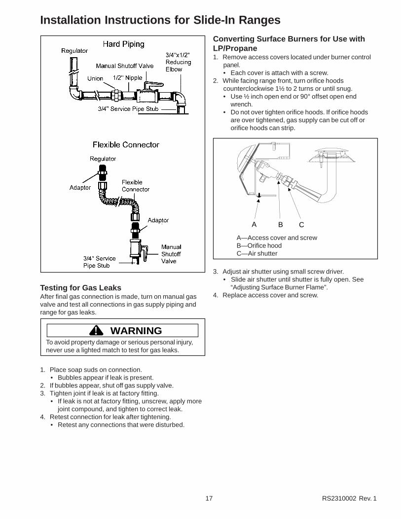
Gas ConnectionConnect gas supply to regulator using hard pipe or aflexible connector. Pressure regulator supplied with thisappliance has a ½ inch NPT female connection. If gasunion is used, remove storage drawer, slide range intoplace, and connect union. See illustration.
• A manual shutoff, not supplied with range, must beinstalled in an accessible location outside of range.
• Use joint compound that is resistant to action ofpropane gas on all male pipe threads.
• Use supplied pressure regulator only.• Do not overtighten gas fitting when attaching to
pressure regulator. Overtightening may crack regulator.• Support pressure regulator with wrench when installing
gas fitting.
WARNING!To avoid property damage or personal injury, only use anew flexible connector that is AGA/CGA designcertified.
• Do not use an old connector.• Do not reuse a connector after moving
appliance.
17 RS2310002 Rev. 1
Installation Instructions for Slide-In Ranges
Testing for Gas LeaksAfter final gas connection is made, turn on manual gasvalve and test all connections in gas supply piping andrange for gas leaks.
WARNING!To avoid property damage or serious personal injury,never use a lighted match to test for gas leaks.
1. Place soap suds on connection.• Bubbles appear if leak is present.
2. If bubbles appear, shut off gas supply valve.3. Tighten joint if leak is at factory fitting.
• If leak is not at factory fitting, unscrew, apply morejoint compound, and tighten to correct leak.
4. Retest connection for leak after tightening.• Retest any connections that were disturbed.
Converting Surface Burners for Use withLP/Propane1. Remove access covers located under burner control
panel.• Each cover is attach with a screw.
2. While facing range front, turn orifice hoodscounterclockwise 1½ to 2 turns or until snug.• Use ½ inch open end or 90° offset open end
wrench.• Do not over tighten orifice hoods. If orifice hoods
are over tightened, gas supply can be cut off ororifice hoods can strip.
A B C
A—Access cover and screwB—Orifice hoodC—Air shutter
3. Adjust air shutter using small screw driver.• Slide air shutter until shutter is fully open. See
“Adjusting Surface Burner Flame”.4. Replace access cover and screw.

RS2310002 Rev. 1 18
Installation Instructions for Slide-In RangesConverting Oven Burner for Use with LP/Propane1. Remove storage drawer.
• See “Removing Storage Drawer” section.2. Locate and remove screws attaching Z-shaped cover
plate.• Cover plate located in center, rear of storage drawer
cavity.• Removing cover plate exposes oven burner orifice
and air shutter.
C
A
B
A—Air shutter screwB—Orifice hoodC—Air shutter
3. Turn orifice hood clockwise until snug.• Do not over tighten orifice hood. Orifice hood can
strip.• Support tubing/fitting with wrench while turning
hood .4. Replace cover plate and storage drawer.
Converting Broiler Burner for Use with LP/Propane1. Locate orifice spud attached adjacent to pressure
regulator and remove for later use.• Orifice spud used for LP/propane gas is silver and
is stamped “58”.
Orifice Spud
Natural Gas—52LP/Propane—58
2. Open oven door and locate broiler burner on ovenceiling.• Remove oven door to make conversion easier. See
“Removing Oven Door” section.3. Remove screws securing front of burner to oven
ceiling and remove broiler.• Be careful not to damage ignitor while removing
broiler.
4. Unscrew natural gas burner spud stamped “52” with5/16 inch socket wrench and replace with LP/propaneburner spud stamped “58”.• Attach unused burner spud near regulator for future
use.5. Reinstall broiler and, if necessary, oven door.
Converting Type 1 Pressure Regulator forUse with Natural Gas1. Remove pressure regulator cap using a 7/8 inch
wrench.2. Remove plastic insert from pressure regulator cap.
• Plastic insert fits tightly in cap.3. Reverse plastic insert and carefully push plastic insert
firmly into hole in pressure regulator cap.• Insert must show “NAT” or be blank.
4. Place pressure regulator cap on pressure regulatorand tighten.• Insert should not disturb spring in body of regulator.
Converting Type 2 Pressure Regulator forUse with Natural Gas1. Remove pressure regulator cap using a 7/8 inch
wrench.2. Reverse pressure regulator cap.
• Insert shows “NAT” or is blank.3. Place pressure regulator cap on pressure regulator
and tighten.
Converting Surface Burners for Use withNatural Gas1. Remove access covers located under burner control
panel.• Each cover is attached with a screw.
2. While facing range front, turn orifice hoods clockwise1½ to 2 turns.• Use ½ inch open end or 90° offset open end
wrench.• Do not over tighten orifice hoods. If orifice hoods
are over tightened, gas supply can be cutoff ororifice hoods can strip.
A B C
A—Access coversB—Orifice hoodC—Air shutter

19 RS2310002 Rev. 1
Installation Instructions for Slide-In Ranges
Gas ConnectionConnect gas supply to regulator using hard pipe or aflexible connector. Pressure regulator supplied with thisappliance has a ½ inch NPT female connection.
• A manual shutoff, not supplied with range, must beinstalled in an accessible location outside of range.
• Use joint compound that is resistant to action ofpropane gas on all male pipe threads.
• Use supplied pressure regulator only.• Do not overtighten gas fitting when attaching to
pressure regulator. Overtightening may crack regulator.• Support pressure regulator with wrench when installing
gas fitting.
WARNING!To avoid property damage or personal injury, only use anew flexible connector that is AGA/CGA designcertified.
• Do not use an old connector.• Do not reuse a connector after moving
appliance.
A— To regulatorB—UnionC—NippleD—Manual shutoff valveE—¾ inch to ½ inch reducing elbowF—¾ inch service pipe stub
A—To regulatorB—AdaptorC—Flexible connectorD—Manual shutoffE—¾ inch service pipe stub
3. Adjust air shutter using small screw driver.• Slide air shutter until shutter is approximately
1/8 inch open.4. Replace access cover and screw.
Converting Oven Burner for Use withNatural Gas1. Remove storage drawer.
• See “Removing Storage Drawer” section.2. Locate and remove screws attaching Z-shaped cover
plate.• Cover plate located in center, rear of storage drawer
cavity.• Removing cover plate exposes oven burner orifice
and air shutter.3. Turn orifice hood counterclockwise 2 full turns,
support tubing/fitting with wrench while turning.4. Replace cover plate and storage drawer.
Converting Broiler Burner for Use withNatural Gas1. Locate orifice spud attached adjacent to pressure
regulator and remove for later use.• Orifice spud used for natural gas is brass and is
stamped “52”.2. Open oven door and locate broiler burner on oven
ceiling.• Remove oven door to make conversion easier. See
“Removing Oven Door” section.3. Remove screws securing front of burner to oven
ceiling and remove broiler.• Be careful not to damage ignitor as you remove
broiler.4. Unscrew LP/Liquid Propane burner spud stamped “58”
with 5/16 inch socket wrench and replace with naturalgas burner spud stamped “52”.
5. Reinstall broiler and, if necessary, oven door.
Gas Supply Pressure
WARNING!To avoid property damage, maximum gas supplypressure must not exceed 14" WCP.
• Appliance and individual shutoff valve must bedisconnected from the gas supply piping system duringany pressure testing of that system at test pressuresin excess of ½ psig (3.5kPa)(14" WCP).
• Appliance must be isolated from gas supply pipingsystem by closing manual shutoff valve during anypressure testing of the gas supply piping system attest pressures equal to or less than ½ psig (3.5kPa)(14" WCP).
• Gas supply pressure for checking regulator settingmust be at least 1" WCP above manifold pressureshown on rating label.

RS2310002 Rev. 1 20
Installation Instructions for Slide-In RangesLevel RangeCarefully level range using legs provided. Range must belevel to cook and bake uniformly.
CAUTION!To avoid damaging oven door, do not lift or move rangeby oven door handle. Glass can break.
• Place a level on top oven rack or on top of range whenleveling.
• Leveling legs must be extended a minimum of¼ inch to engage anti-tip bracket.
1. Extend leveling legs so when range is moved intoposition range top clears counter top.
2. Slide range to where it will be installed.• Position range so rear leveling legs do not engage
anti-tip bracket.3. Turn leveling legs to level range.
• Turn legs clockwise to decrease range height orcounter clockwise to increase range height.
• Adjust rear leveling leg that engages anti-tipbracket first. Leveling leg can not be adjusted whilein bracket. After adjusting leg that engages anti-tipbracket, slide range until leg engages bracket, andadjust other legs.
4. Replace storage drawer.
Placing Burner CapsTo replace burner caps after cleaning, make sure cap isproperly aligned and leveled. Verify locating pegs in theburner body fit into recess in underside of burner cap.Burner cap must be correctly seated on burner body forproper operation of burner. Burner will not burn properly ifwrong size burner cap is placed on wrong size burnerbody. Check for ignition after placement.
Burner cap
Burner body
Testing for Gas LeaksAfter final gas connection is made, turn on manual gasvalve and test all connections in gas supply piping andrange for gas leaks.
WARNING!To avoid property damage or serious personal injury,never use a lighted match to test for gas leaks.
1. Place soap suds on connection.• Bubbles appear if leak is present.
2. If bubbles appear, shut off gas supply valve.3. Tighten joint if leak is at factory fitting.
• If leak is not at factory fitting, unscrew, apply morejoint compound, and tighten to correct leak.
4. Retest connection for leak after tightening.• Retest any connections that were disturbed.
Removal and Replacement of Range1. Disconnect power to range.2. Slide range forward.3. Unplug range cord and place range aside.4. Remove anti-tip bracket.5. Install anti-tip bracket into new location using
instructions provided with bracket or see “Anti-tipBracket Installation” section.
6. To reinstall range, follow instructions in “Installation”section.
Seal OpeningsOpenings in wall behind the range or on floor under rangemust be sealed before sliding range into position.

21 RS2310002 Rev. 1
Installation Instructions for Slide-In Ranges
Adjusting Surface Burner FlameIgnite burner according to “Operating Surface Burners”section. Properly adjusted burner flames are clean andblue with a distinct inner cone approximately ½ inchlong.
ABurner
Inner coneA—¼ inch to ½ inch long
1. Ignite burner.2. Remove access covers located under burner control
panel.• Each cover is attached with a screw.
A B
A—Access coversB—Air shutter
3. Adjust air shutter using small screwdriver. Use smallscrewdriver to slide air shutter.• If burner flame is blowing or noisy, reduce airflow to
burner. Repeat until flame is properly adjusted ifnecessary.
• If burner flame is yellow and does not hold itsshape, increase airflow to burner. Repeat untilflame is properly adjusted if necessary.
Adjusting Surface Burner Low Flame Size1. Push and turn burner control knob to “LITE” position.
• Burner sparks until turned from “LITE”.2. Set burner control knob to low setting.3. Remove burner control knob.4. While holding valve stem stationary, turn screw in
center of burner control stem until flame is adjusted.• Use small standard screwdriver.
5. Replace burner control knob.6. Turn surface burner control on and off to test burner
flame.7. If flame is adjusted too low, flame may be easily
extinguished. Burner can be extinguished by drafts,door opening or closing, heating and cooling vents,ceiling fans, etc.
Adjusting Oven Burner FlameProperly adjusted oven burner flames are clean and bluewith a distinct inner cone approximately ½ inch long.
• If burner flame is blowing or noisy, reduce airflow toburner.
• If burner flame is yellow and does not hold its shape,increase airflow to burner.
1. Remove storage drawer.• See “Removing Storage Drawer” section.
2. Locate and remove screws attaching Z-shaped coverplate.• Cover plate located in center, rear of storage drawer
cavity.• Removing cover plate exposes oven burner orifice
and air shutter.
C
A
B
A—Air shutter lock screwB—Orifice hoodC—Air shutter
3. Loosen air shutter lock screw and open or close airshutter.• Tighten air shutter lock screw after adjusting.
4. Replace cover plate and storage drawer.
Broiler FlameBroiler flame should appear hazy or fuzzy. Haze shouldbe approximately 3/8 inch thick. Because broiler has afixed orifice it can not be adjusted. Broiler does not havean air shutter.
RS2310002 Rev. 1 22
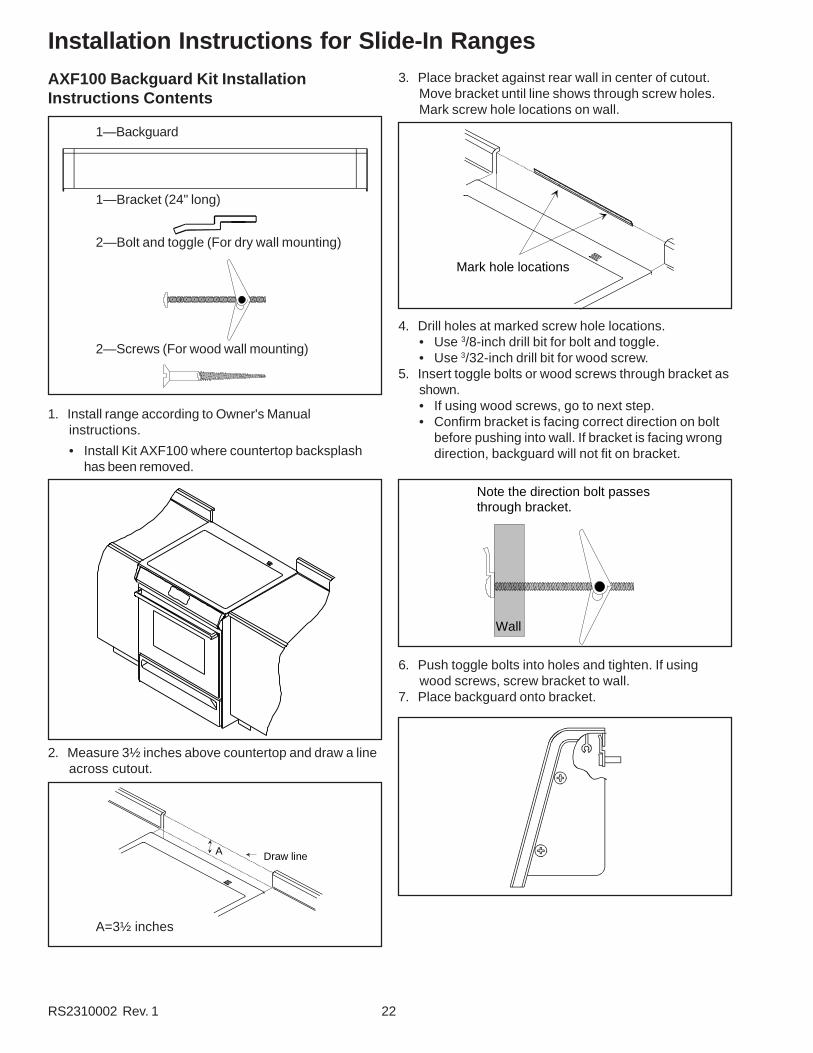
Installation Instructions for Slide-In RangesAXF100 Backguard Kit InstallationInstructions Contents
1—Backguard
1—Bracket (24" long)
2—Bolt and toggle (For dry wall mounting)
2—Screws (For wood wall mounting)
1. Install range according to Owner's Manualinstructions.
• Install Kit AXF100 where countertop backsplashhas been removed.
2. Measure 3½ inches above countertop and draw a lineacross cutout.
A Draw line
A=3½ inches
3. Place bracket against rear wall in center of cutout.Move bracket until line shows through screw holes.Mark screw hole locations on wall.
Mark hole locations
4. Drill holes at marked screw hole locations.• Use 3/8-inch drill bit for bolt and toggle.• Use 3/32-inch drill bit for wood screw.
5. Insert toggle bolts or wood screws through bracket asshown.• If using wood screws, go to next step.• Confirm bracket is facing correct direction on bolt
before pushing into wall. If bracket is facing wrongdirection, backguard will not fit on bracket.
Note the direction bolt passes through bracket.
Wall
6. Push toggle bolts into holes and tighten. If usingwood screws, screw bracket to wall.
7. Place backguard onto bracket.

23 RS2310002 Rev. 1
Installation Instructions for Freestanding Ranges
Packing MaterialRemove protective packing materials from range. Taperesidue can be cleaned with a soft cloth and alcohol.
Range LocationChoose a location based on following factors.
• Drafts caused by home heating and air conditioningand open doors or windows can disrupt ventilation airpattern. Range should not be installed near windows ordoors.
• Make sure there is adequate space for properinstallation.
• Carefully read all instructions before beginninginstallation.
Cabinet Opening
WARNING!To avoid risk of burns or fire by reaching over burners,cabinet storage space located above range should beavoided.
Range should extend approximately 2 inches fromcabinet front to oven door handle. Use dimensions inillustration below and shown in “Special Counter topConditions” section to prepare cabinet opening.
Standard Cabinet and Counter top Height
35"
Wall
1"
Width—30 inchesDepth—25 inches (Rear standoffs to
side panel front)Height—36 inches
Minimum Clearances to CombustibleSurfaces• Minimum clearance to rear wall is 0 inches.• Minimum clearance to a vertical right or left side wall
extending above cooking surface is 3 inches.• Minimum clearance to counter top/cabinet on each
side is 0 inches.• Minimum of 30 inches between top of cooking surface
and bottom of an unprotected wood or metal cabinet.• 24 inches between cooking surface and protected wood
or metal cabinet above range. Cabinet bottom must beprotected by at least ¼ inch thick millboard with notless than No. 28 MSG sheet steel, .015 inch thickstainless steel, .024 inch thick aluminum, or .020 inchthick copper.
A
B
C
D
E
FG
A—30 inches unprotected/24 inches protected minimum
B—3 inches (Both sides of range)C—18 inches minimumD—0 inchesE—301/8 inches minimumF—13 inches maximumG—0 inches

RS2310002 Rev. 1 24
Installation Instructions for Freestanding Rangesside of cabinet cutout. Mark measurements on floorand draw a straight line connecting marks.
2. Position anti-tip bracket.• If range is installed beside cabinet(s), place anti-tip
bracket with back edge on line drawn on floor andside of bracket against cabinet.
• If range is not installed beside cabinet(s), positionrange where it will be installed. Draw a line alongside of range on floor from front to back. Removerange. Place anti-tip bracket with back edge overline drawn 31/2 inches from back wall and side ofbracket over line drawn along side of range on floor.
• Anti-tip bracket can be installed on either right orleft side.
3. Mark 2 hole locations in anti-tip bracket.4. Drill 2 holes.
• If drilling into wood, use a 3/32 inch drill bit.• If drilling into concrete, use a 3/16 inch masonry drill
bit and insert plastic anchors.5. Secure bracket to floor using screws supplied.6. Slide range into position.7. Remove range storage drawer and confirm anti-tip
bracket is engaged with range leveling leg.
Electrical Connection Requirements
Special Counter Top ConditionsCountertops such as ceramic tile tops cause cabinet andcounter top to be higher than 36 inches. Followinstructions below when counter top is higher than 36inches.
1. Raise leveling legs to maximum level.2. Measure from floor to side trim. If measurement is
less than height of countertop floor must be shimmed.3. Shim floor using a piece of plywood same size as
range opening. Secure plywood to floor. Plywoodmust be as secure as original flooring.
4. Install anti-tip bracket(s) and slide range into place.
Anti-tip Bracket InstallationTo reduce risk of range tipping, secure range with aproperly installed anti-tip bracket(s). Use eitherrectangular or L-shaped anti-tip bracket(s) packed withrange. Follow appropriate instructions.
L-shaped Anti-tip Brackets1. Measure 51/8 inches from back wall on right and left
side of cabinet cutout. Mark measurements on floorand draw a straight line connecting marks.
2. Position anti-tip brackets with inside edge over linedrawn on floor and end of bracket against cabinet.• If range is not installed beside cabinet(s), position
range where it will be installed. Draw a line alongside of range on floor from front to back. Removerange. Place anti-tip brackets with inside edge overline drawn 51/8 inches from back wall and end ofbracket over line drawn along side of range on floor.
• Anti-tip bracket must be installed on both right andleft side.
5 1/8"
3. Mark hole locations in each anti-tip bracket.4. Drill holes.
• If drilling into wood, use a 3/32 inch drill bit.• If drilling into concrete, use a 3/16 inch masonry drill
bit and insert plastic anchors.5. Secure brackets to floor using screws supplied.6. Slide range into position.7. Remove range storage drawer and confirm anti-tip
brackets is engaged with range leveling leg.
Rectangular Anti-tip Bracket1. Measure 31/2 inches from back wall on right and left

25 RS2310002 Rev. 1
Installation Instructions for Freestanding Ranges
WARNING!To avoid the risk of serious electrical shock or propertydamage, do not cut or remove the third (ground) prongfrom the power plug. A 3-wire grounded conductorsystem must be used. Relying on the flexibleconnector, hard piping or any other part of the gassupply line as a ground may cause fire, electricalshock and/or erratic control operation.
Range must be electrically grounded in accordance withlocal codes or in the absence of local codes, with theNational Electrical Code, ANSI/NFPA No. 70-LatestEdition. In Canada, electrical connections are to made inaccordance with CSA C22.1 Canadian Electrical Code.
Use a dedicated 120 volt, 60 hertz, 3-prong receptacleprotected by a 15 amp circuit breaker or time delay fuse.A qualified electrician should confirm the outlet isproperly grounded.
If a 2-prong outlet is encountered, range owner mustreplace outlet before using range. Do not cut off cord, useplug adapter, remove grounding plug, or use extensioncord.
Electrical Connection ClearanceElectrical connection must be located in the area shownin illustration below. Electrical connection must notinterfere with gas connection.
A
BC
D
A—2 inches (Both sides)B—19½ inchesC—12 inchesD—6 inches
Gas Connection Requirements
Before connecting this appliance to the gas supply pipingsystem, confirm installation meets the requirements oflocal codes, or in the absence of local codes, with theNational Fuel Gas Code, ANSI Z223.1-Latest Edition. InCanada installation must conform with local codes or thecurrent Natural Gas Installation Code CAN/CGA-B149.1.
Gas Supply LocationGas supply must be located in the ilustration shownbelow. Gas connection must not interfere with theelectrical connection.
AB
C D
A
B
A—26 inchesB—20 inchesC—2¼ inchesD—4 inches
Gas Supply Pressure
WARNING!To avoid property damage, maximum gas supplypressure must not exceed 14” WCP.
• Appliance and individual shutoff valve must bedisconnected from the gas supply piping system duringany pressure testing of that system at test pressuresin excess of ½ psig (3.5kPa)(14" WCP).
• Appliance must be isolated from gas supply pipingsystem by closing manual shutoff valve during anypressure testing of the gas supply piping system attest pressures equal to or less than ½ psig (3.5kPa)(14" WCP).
• Gas supply pressure for checking regulator settingmust be at least 1" WCP above manifold pressureshown on rating label.
Pressure Regulator Location
RS2310002 Rev. 1 26
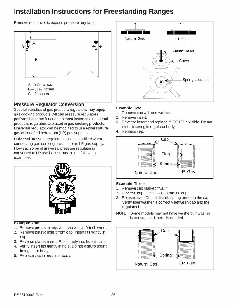
Installation Instructions for Freestanding RangesRemove rear cover to expose pressure regulator.
A
B
C
A—3¾ inchesB—31½ inchesC—2 inches
Pressure Regulator ConversionSeveral varieties of gas pressure regulators may equipgas cooking products. All gas pressure regulatorsperform the same function. In most instances, universalpressure regulators are used in gas cooking products.Universal regulator can be modified to use either Naturalgas or liquefied petroleum (LP) gas supplies.
Universal pressure regulator, must be modified whenconnecting gas cooking product to an LP gas supply.How each type of universal pressure regulator isconverted to LP use is illustrated in the followingexamples.
Example One1. Remove pressure regulator cap with a 7/8-inch wrench.2. Remove plastic insert from cap. Insert fits tightly in
cap.3. Reverse plastic insert. Push firmly into hole in cap.4. Verify insert fits tightly in hole. Do not disturb spring
in regulator body.5. Replace cap in regulator body.
Natural Gas L.P. Gas
Plastic Insert
Cover
Spring Location
Example Two1. Remove cap with screwdriver.2. Remove insert.3. Reverse insert and replace. “LPG10” is visible. Do not
disturb spring in regulator body.4. Replace cap.
Natural Gas L.P. Gas
Cap
Plug
Spring
Example Three1. Remove cap marked “Nat.”2. Reverse cap. “LP” now appears on cap.3. Reinsert cap. Do not disturb spring beneath the cap.
Verify fiber washer is correctly between cap and theregulator body.
NOTE: Some models may not have washers. If washeris not supplied, none is needed.
Natural Gas L.P. Gas
Cap
Spring

27 RS2310002 Rev. 1
Installation Instructions for Freestanding RangesExample Four1. Remove cap with screwdriver slot.2. Reverse and replace cap. Verify “LPG10” is visible. Do
not disturb spring beneath cap.
Natural Gas L.P. Gas
Cap
Spring
Example Five1. Remove cap with screwdriver slot.2. Remove black insert marked “NAT.” from cap. Insert
fits tightly in cap.3. Reverse insert.4. Replace in hole. Verify “LP” is visible. Verify that
insert is pressed firmly into shoulder. Do not disturbspring in regulator body.
5. Replace cap in regulator body and tighten.
Natural Gas L.P. Gas
Cap
Insert
Spring
Example Six1. Remove cap with screwdriver slot.2. Remove spring and washer. Washer will be at bottom
of spring as illustrated below.3. Reverse to bring washer to the top.4. Reinstall spring and washer.5. Tighten cap.
Cap
Washer
Natural Gas L.P. Gas
Converting Surface Burners for Use withLP\Propane1. Remove 4 burner control knobs from range.
• Exposes 2 screws on burner control panel.2. Remove 2 screws from burner control panel.
• Panel drops slightly after screws are removed.3. Grasp bottom of burner control panel, gently lift and
pull out panel until clear of burner valve stems.• After burner control panel clears valve stems,
continue to roll panel until free from range. Setaside. See “Pivot Point” in illustration.
• Gas valve and orifice hood are visible after burnercontrol panel is removed.
A
C
D
B
A—Burner Control KnobB—Pivot PointC—Burner Control PanelD—Screw
4. While facing range front, turn orifice hoodscounterclockwise 1½ to 2 turns or until snug.• Use ½ inch open end or 90° offset open end
wrench.• Do not over tighten orifice hoods. If orifice hoods
are over tightened, gas supply can be cutoff ororifice hoods can strip.
A—Orifice HoodB—Air Shutter
5. Reassemble Burner control panel after adjusting airshutter.• See “Adjusting Surface Burner Flame” section.
RS2310002 Rev. 1 28
Installation Instructions for Freestanding Ranges
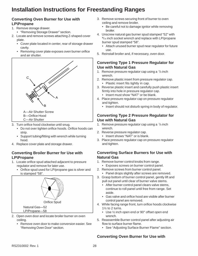
Converting Oven Burner for Use withLP\Propane1. Remove storage drawer.
• “Removing Storage Drawer” section.2. Locate and remove screws attaching Z-shaped cover
plate.• Cover plate located in center, rear of storage drawer
cavity.• Removing cover plate exposes oven burner orifice
and air shutter.
C
A
B
A—Air Shutter ScrewB—Orifice HoodC—Air Shutter
3. Turn orifice hood clockwise until snug.• Do not over tighten orifice hoods. Orifice hoods can
strip.• Support tubing/fitting with wrench while turning
hood.4. Replace cover plate and storage drawer.
Converting Broiler Burner for Use withLP\Propane1. Locate orifice spud attached adjacent to pressure
regulator and remove for later use.• Orifice spud used for LP/propane gas is silver and
is stamped “58”.
Orifice Spud
Natural Gas—52LP/Propane—58
2. Open oven door and locate broiler burner on ovenceiling.• Remove oven door to make conversion easier. See
“Removing Oven Door“ section.
3. Remove screws securing front of burner to ovenceiling and remove broiler.• Be careful not to damage ignitor while removing
broiler.4. Unscrew natural gas burner spud stamped “52” with
5/16 inch socket wrench and replace with LP/propaneburner spud stamped “58”.• Attach unused burner spud near regulator for future
use.5. Reinstall broiler and, if necessary, oven door.
Converting Type 1 Pressure Regulator forUse with Natural Gas1. Remove pressure regulator cap using a 7/8 inch
wrench.2. Remove plastic insert from pressure regulator cap.
• Plastic insert fits tightly in cap.3. Reverse plastic insert and carefully push plastic insert
firmly into hole in pressure regulator cap.• Insert must show “NAT” or be blank.
4. Place pressure regulator cap on pressure regulatorand tighten.• Insert should not disturb spring in body of regulator.
Converting Type 2 Pressure Regulator forUse with Natural Gas1. Remove pressure regulator cap using a 7/8 inch
wrench.2. Reverse pressure regulator cap.
• Insert shows “NAT” or is blank.3. Place pressure regulator cap on pressure regulator
and tighten.
Converting Surface Burners for Use withNatural Gas1. Remove burner control knobs from range.
• Exposes screws on burner control panel.2. Remove screws from burner control panel.
• Panel drops slightly after screws are removed.3. Grasp bottom of burner control panel, gently lift and
pull out panel until clear of burner valve stems.• After burner control panel clears valve stems,
continue to roll panel until free from range. Setaside.
• Gas valve and orifice hood are visible after burnercontrol panel are removed.
4. While facing range front, turn orifice hoods clockwise1½ to 2 turns.• Use ½ inch open end or 90° offset open end
wrench.5. Reassemble Burner control panel after adjusting air
flow to surface burner flame.• See “Adjusting Surface Burner Flame” section.
Converting Oven Burner for Use with

29 RS2310002 Rev. 1
Installation Instructions for Freestanding Ranges
Natural Gas1. Remove storage drawer.
• “Removing Storage Drawer” section.2. Locate and remove screws attaching Z-shaped cover
plate.• Cover plate located in center, rear of storage drawer
cavity.• Removing cover plate exposes oven burner orifice
and air shutter.3. Turn orifice hood counterclockwise 2 full turns.
• Support tubing/fitting with wrench while turninghood.
4. Replace cover plate and storage drawer.
Converting Broiler Burner for Use withNatural Gas1. Locate orifice spud attached adjacent to pressure
regulator and remove for later use.• Orifice spud used for natural gas is silver and is
stamped “52”.2. Open oven door and locate broiler burner on oven
ceiling.• Remove oven door to make conversion easier. See
“Removing Oven Door” section.3. Remove 2 screws securing front of burner to oven
ceiling and remove broiler.• Be careful not to damage ignitor as you remove
broiler.4. Unscrew LP/propane burner spud stamped “58” with
5/16 inch socket wrench and replace with natural gasburner spud stamped “52”.
5. Reinstall broiler and, if necessary, oven door.
Gas ConnectionConnect gas supply to regulator using hard pipe or aflexible connector. Pressure regulator supplied with thisappliance has a ½ inch NPT female connection. If gasunion is used, remove storage drawer, slide range intoplace, and connect union. See figure below.
• A manual shutoff, not supplied with range, must beinstalled in an accessible location outside of range.
• Use joint compound that is resistant to action ofpropane gas on all male pipe threads.
• Use supplied pressure regulator only.• Do not overtighten gas fitting when attaching to
pressure regulator. Overtightening may crack regulator.• Support pressure regulator with wrench when installing
gas fitting.
WARNING!To avoid property damage or personal injury, only use anew flexible connector that is AGA/CGA designcertified.
• Do not use an old connector.• Do not reuse a connector after moving
appliance.
Testing for Gas LeaksAfter final gas connection is made, turn on manual gasvalve and test all connections in gas supply piping andrange for gas leaks.
WARNING!To avoid property damage or serious personal injury,never use a lighted match to test for gas leaks.
1. Place soap suds on connection.• Bubbles appear if leak is present.
2. If bubbles appear, shut off gas supply valve.3. Tighten joint if leak is at factory fitting.
• If leak is not at factory fitting, unscrew, apply morejoint compound, and tighten to correct leak.
4. Retest connection for leak after tightening.• Retest any connections that were disturbed.

RS2310002 Rev. 1 30
Installation Instructions for Freestanding Ranges
Seal OpeningsOpenings in wall behind the range or on floor under rangemust be sealed before sliding range into position.
Place RangePlug in range. Slide range into place. Carefully levelrange using legs provided. Range must be level to cookand bake uniformly.
• Place a level on top oven rack or on top of range whenleveling.
• Leveling legs must be extended out ¼ inch to engageanti-tip bracket.
Removal and Replacement of Range1. Unplug range cord.2. Turn off gas valve and disconnect gas supply.3. Remove range and place aside.4. Remove anti-tip bracket and reinstall anti-tip bracket
into new location using instructions provided withbracket.
5. To reinstall range, follow instructions in this manual.• Do not reuse a flexible connector after moving
appliance.
Adjusting Surface Burner FlameProperly adjusted surface burner flames are clean andblue with a distinct inner cone approximately ¼ inch to ½inch long. See “Operating Surface Burners” section forburner operating instructions.
WARNING!To avoid electric shock that can cause personal injuryor death, disconnect main electrical supply to rangebefore servicing.
• If burner flame is blowing or noisy, reduce airflow toburner.
• If burner flame is yellow and does not hold its shape,increase airflow to burner.
Outer Mantle - Dark Blue
Inner Cone - Blue-Green
Adjusting Air Shutter1. Remove burner control knobs from range.
• Exposes screws on burner control panel.2. Remove screws from burner control panel.
• Panel drops slightly after screws are removed.3. Grasp bottom of burner control panel, gently lift and
pull out panel until clear of burner valve stems.• After burner control panel clears valve stems,
continue to roll panel until free from range. Setaside. See “Pivot Point” in illustration.
• Gas valve and orifice hood are visible after burnercontrol panel are removed.
A
C
D
B
A—Burner Control KnobB—Pivot PointC—Burner Control PanelD—Screw
4. Slide air shutter open or closed depending onappearance of burner flame.• If flame is yellow and does not hold its shape, open
air shutter.• If flame is blowing or noisy, close air shutter.
A—Orifice HoodB—Air Shutter
5. Reassemble Burner control panel.

31 RS2310002 Rev. 1
Installation Instructions for Freestanding Ranges
Adjusting Surface Burner Low Flame Size1. Push and turn burner control knob to “LITE” position.
• Burner sparks until gas ignites.2. Set burner control knob to low setting.3. Remove burner control knob.4. While holding valve stem stationary, turn screw in
center of burner control stem until flame is adjusted.• Use small standard screwdriver.
5. Replace burner control knob.6. Turn surface burner control on and off to test burner
flame.
Broiler FlameBroiler flame should appear hazy or fuzzy. Haze shouldbe approximately 3/8 inch thick. Because broiler has afixed orifice it can not be adjusted. Broiler does not havean air shutter.
Adjusting Oven Burner FlameProperly adjusted oven burner flames are clean and bluewith a distinct inner cone approximately ½ inch long.
• If burner flame is blowing or noisy, reduce airflow toburner.
• If burner flame is yellow and does not hold its shape,increase airflow to burner.
WARNING!To avoid electric shock that can cause personal injuryor death, disconnect main electrical supply to rangebefore servicing.
1. Remove storage drawer.• “Removing Storage Drawer” section.
2. Locate and remove screws attaching Z-shaped coverplate.• Cover plate located in center, rear of storage drawer
cavity.• Removing cover plate exposes oven burner orifice
and air shutter.
C
A
B
A—Air Shutter Lock ScrewB—Orifice HoodC—Air Shutter
3. Loosen air shutter lock screw and open or close airshutter.• Tighten air shutter lock screw after adjusting.
4. Replace cover plate and storage drawer.
Broiler FlameBroiler flame should appear hazy or fuzzy. Haze shouldbe approximately 3/8 inch thick. Because broiler has afixed orifice it can not be adjusted. Broiler does not havean air shutter.
Placing Burner CapsTo replace burner caps after cleaning, make sure cap isproperly aligned and leveled. Verify locating pegs in theburner body fit into recess in underside of burner cap.Burner cap must be correctly seated on burner body forproper operation of burner. Burner will not burn properly ifwrong size burner cap is placed on wrong size burnerbody. Check for ignition after placement.
Burner cap
Burner body

RS2310002 Rev. 1 32
Installation Instructions for Freestanding Ranges
Level RangeCarefully level range using legs provided. Range must belevel to cook and bake uniformly.
CAUTION!To avoid damaging oven door, do not lift or move rangeby oven door handle. Glass can break.
• Place a level on top oven rack or on top of range whenleveling.
• Leveling legs must be extended a minimum of¼ inch to engage anti-tip bracket.
1. Extend leveling legs so when range is moved intoposition range top clears counter top.
2. Slide range to where it will be installed.• Position range so rear leveling legs do not engage
anti-tip bracket.3. Turn leveling legs to level range.
• Turn legs clockwise to decrease range height orcounter clockwise to increase range height.
• Adjust rear leveling leg that engages anti-tipbracket first. Leveling leg can not be adjusted whilein bracket. After adjusting leg that engages anti-tipbracket, slide range until leg engages bracket, andadjust other legs.
4. Replace storage drawer.
Removal and Replacement of Range1. Disconnect power to range.2. Slide range forward.3. Unplug range cord and place range aside.4. Remove anti-tip bracket.5. Install anti-tip bracket into new location using
instructions provided with bracket or see “Anti-tipBracket Installation” section.
6. To reinstall range, follow installation instructions.
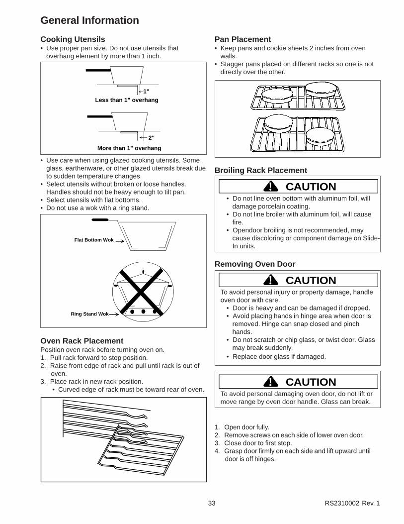
33 RS2310002 Rev. 1
Cooking Utensils• Use proper pan size. Do not use utensils that
overhang element by more than 1 inch.
1"
2"
Less than 1" overhang
More than 1" overhang
• Use care when using glazed cooking utensils. Someglass, earthenware, or other glazed utensils break dueto sudden temperature changes.
• Select utensils without broken or loose handles.Handles should not be heavy enough to tilt pan.
• Select utensils with flat bottoms.• Do not use a wok with a ring stand.
Flat Bottom Wok
Ring Stand Wok
Oven Rack PlacementPosition oven rack before turning oven on.1. Pull rack forward to stop position.2. Raise front edge of rack and pull until rack is out of
oven.3. Place rack in new rack position.
• Curved edge of rack must be toward rear of oven.
Pan Placement• Keep pans and cookie sheets 2 inches from oven
walls.• Stagger pans placed on different racks so one is not
directly over the other.
Broiling Rack Placement
CAUTION!• Do not line oven bottom with aluminum foil, will
damage porcelain coating.• Do not line broiler with aluminum foil, will cause
fire.• Opendoor broiling is not recommended, may
cause discoloring or component damage on Slide-In units.
Removing Oven Door
CAUTION!To avoid personal injury or property damage, handleoven door with care.
• Door is heavy and can be damaged if dropped.• Avoid placing hands in hinge area when door is
removed. Hinge can snap closed and pinchhands.
• Do not scratch or chip glass, or twist door. Glassmay break suddenly.
• Replace door glass if damaged.
CAUTION!To avoid personal damaging oven door, do not lift ormove range by oven door handle. Glass can break.
1. Open door fully.2. Remove screws on each side of lower oven door.3. Close door to first stop.4. Grasp door firmly on each side and lift upward until
door is off hinges.
General Information

RS2310002 Rev. 1 34
• Do not lift door by handle. Glass can break.• Only push hinges closed once oven door is
removed if necessary. Use both hands whenclosing hinge. Hinge snaps closed.
Replacing Oven Light
WARNING!To avoid risk of burns or electrical shock, disconnectelectrical supply to range before changing light bulb.
• Before replacing light bulb make sure bulb is cool.• Wear protective gloves.• Do not operate oven without bulb and cover in
place.
1. Disconnect electrical supply.2. Remove oven door if desired.3. Unscrew light bulb cover if so equiped and then light
bulb. Turn counterclockwise.4. Replace light bulb with 120 volt, 40 watt appliance
bulb.• Do not overtighten bulb or light bulb cover. They
may be difficult to remove later.5. Replace light bulb cover and oven door before use.6. Reconnect power supply.
Replacing Backguard Panel Light1. Lift up front edge of backguard top trim. Flip top trim
towards rear of backguard.2. Twist fluorescent bulb to remove it from the sockets.
CAUTION!Wear gloves to protect hands from accidental bulbbreakage.
Removing Storage Drawer1. Slide drawer out until it stops.2. Grasp drawer sides near back of drawer.3. Lift up and out.
• Reverse to reinstall.
Replacing Burner CapsTo replace burner caps after cleaning, make sure cap isproperly aligned and leveled. Verify locating pegs in theburner body fit into recess in underside of burner cap.Burner cap must be correctly seated on burner body forproper operation of burner. Burner will not burn properly ifwrong size burner cap is placed on wrong size burnerbody. Check for ignition after placement.
Burner cap
Burner body
Replacing Drip PansDrip pans may be removed for cleaning. When replacingDrip pans after cleaning, holes in drip pan must matchproperly with burners. Drip pans will fit properly only oneway.
General Information

35 RS2310002 Rev. 1
Cleaning
Care and Cleaning
Part Materials to Use General DirectionsBurner Caps and
GratesSoap and Water Cool before cleaning. Frequent cleaning with soap
and water, and non-abrasive pad prolongs timebetween deep cleanings. Be sure to drythoroughly.
Hard to CleanBurner Caps and
Grates
½ Cup Ammonia Place burner caps and grates in plastic bag with ½cup ammonia. Do not pour ammonia into bag.Ammonia must remain in cup. To avoid rust, donot soak grates in ammonia. Close bag tightly andleave grate and caps overnight. Before bag isopened turn face away to avoid breathing or eyecontact with fumes. Remove burner caps andgrates from bag and rinse. Clean according toinstructions above.
Broiler Pan andGrid
Soap and a Non-abrasivePlastic Scouring Pad
Drain fat, cool pan and grid slightly. (Do not letsoiled pan and grid stand in oven to cool.) Sprinklewith soap. Fill the pan with warm water. Let panand grid stand for a few minutes. Wash or scour ifnecessary. Rinse and dry. The broiler pan and gridmay also be cleaned in the dishwasher.
Control Knobs Mild Soap and Water Pull off knobs. Wash gently but do not soak. Dryand return controls to oven, making sure to matchflat area on the knob to the flat area on shaft.
Inside Oven Door Soap and Water Clean the outside of the door and the window areawith warm soapy water. Do not clean the ovendoor gasket. Gasket should not be moved whilecleaning. Avoid getting any cleaning materials ongasket.
Outside Finish andBackguard
Soap and Water Wash all glass with cloth dampened in soapywater. Rinse and polish with a dry cloth. If knobsare removed, do not allow water to run down insidesurface while cleaning.
Oven InteriorSurfaces
Soap and Water Cool before cleaning. Frequent wiping with mildsoap and water prolongs time betweenself-cleanings. Be sure to rinse thoroughly.
Oven Racks andStorage Drawer
Soap and Water For heavy soil, clean by hand and rinse thoroughly.Remove the drawer and racks for ease incleaning. Be sure drawer is dry before replacing.
Drip Pans Soap and a Non-abrasivePlastic Scouring Pad
Sprinkle with soap. Fill the pan with warm water.Let pan stand for a few minutes. Wash or scour ifnecessary. Rinse and dry. Drip pans may also becleaned in dishwasher.

RS2310002 Rev. 1 36
Operating Instructions
Operating Surface Burners
WARNING!To avoid risk of serious personal injury, propertydamage, or fire, do not leave burners unattendedwhile in operation. Grease and spillovers can ignitecausing a fire.
Refer to individual technical sheets for specific informationon element ratings.
1. Push in and turn control knob counterclockwise to“LITE” position.
• All burner will spark.
Typical Control Knobs
2. After gas ignites, turn control to desired setting.• Each control knob can be set to any required
cooking temperature. Burner settings do not havedistinct clicks.
• Use “HI” to bring food to boiling temperatures.When food is boiling temperature setting should bereduced.
3. Turn control knob to “OFF” position when finishedcooking.• If left in "LITE" position, ignitor will continue to
spark.
Operating Surface Burner during a PowerFailureAlthough system that ignites the burners is electric,surface burners can be ignited during a power failure.Never attempt to light bake or broil burners during powerfailure.
1. Hold match at base of desired burner.2. Push in burner control knob and turn to “LITE”
position.3. After gas ignites, remove match from burner and turn
burner control knob to desired setting.
Oven Light• Used to light inside of oven.• Brightens oven cavity when oven door is opened or
panel switch is turned on.• Switch is located on right side of control panel next to
clock.• Operates automatically when oven door is opened.
OVEN LIGHT
Panel Light• Used to light backguard and illuminate cooking
surface.• Switch is located on left side of control panel next to
clock.
PANEL LIGHT

Testing ProceduresTTTTTo ao ao ao ao avvvvvoid the risk of electric shocoid the risk of electric shocoid the risk of electric shocoid the risk of electric shocoid the risk of electric shoc k,k,k,k,k, per per per per personal injursonal injursonal injursonal injursonal injur y ory ory ory ory ordeath, disconnect power before servicing, unless testingdeath, disconnect power before servicing, unless testingdeath, disconnect power before servicing, unless testingdeath, disconnect power before servicing, unless testingdeath, disconnect power before servicing, unless testingrequires it.requires it.requires it.requires it.requires it.
WARNING!
37 RS2310002 Rev. 1
Fluorescent Light Ballast1. Turn off power to the range.2. Remove wires connected to ballast, and measure
from terminal to terminal.• If infinite or zero resistance is indicated replace
ballast.• Resistance should be indicated, but not a direct
short.
Fluorescent Light StarterIf light does not illuminate verify voltage to ballast. Ifvoltage is present, and ballast check OK, replace starter.
Fluorescent LightIf fluorescent tube has blackened ends and lightflicker's, verify proper connection of tube, or replacetube.
Oven Light SwitchThe oven light switch is a single pole, single throwrocker type switch mounted in the control panel. Followthe procedures below to test the switch.
1. Turn off power to the range.2. Disconnect the switch wire leads.3. Attach an ohmmeter, set to the R x 1 scale, to the
switch terminals 1 and 2. When the switch is set tothe ON position, continuity should be indicated andopen contacts should be indicated when the switchis set to the OFF position.
Oven Door SwitchClean Safety/Light Switch (Power Off)1. The switch has NO (normally open), NC (normally
closed), and C (common) contacts.2. Check the switch with an ohmmeter between C and
NC with the plunger out. Continuity should exist.With the plunger in, no continuity.
3. Check the switch with an ohmmeter between C andNO with the plunger in. Continuity should exist. Withthe plunger out, no continuity.
C
NO NCNOTE: When facing the range, the switch is on the left.
Oven High Limit/Fan SwitchLocated on the rear of unit and connecting to the L2 sideof electric supply, this switch is normally closed but willopen if external temperature exceeds limits listed below.
Part Number Open Close308417 115°F 155°F316971 240°F 210°F
1. Turn off power to range.2. Remove lower rear access panel on back of range.3. Disconnect wires from switch terminal connections.4. Attach ohmmeter leads to switch terminals. At
ambient room temperature (70°F.) continuity shouldbe indicated.

Testing ProceduresTTTTTo ao ao ao ao avvvvvoid the risk of electric shocoid the risk of electric shocoid the risk of electric shocoid the risk of electric shocoid the risk of electric shoc k,k,k,k,k, per per per per personal injursonal injursonal injursonal injursonal injur y ory ory ory ory ordeath, disconnect power before servicing, unless testingdeath, disconnect power before servicing, unless testingdeath, disconnect power before servicing, unless testingdeath, disconnect power before servicing, unless testingdeath, disconnect power before servicing, unless testingrequires it.requires it.requires it.requires it.requires it.
WARNING!
RS2310002 Rev. 1 38
Gas ThermostatThis system uses a thermostat which internally selectsthe Bake, Broil, and Clean circuits eliminating theseparate selector switch.
Verify voltage being supplied to the gas thermostat bymeasuring voltage at terminal 2 of the gas thermostat,meter should indicate 120 VAC.
Verify gas thermostat is working correctly by measuringvoltage at BA in bake mode, BR in broil mode, and C inclean mode. All terminal points should indicate 120 VAC.
Dial Contacts 1-2Main COM-NO COM-NC C-BR C-BA 7-9
Low Stop N.S. O X O O OBake Cycles N.S. N.S. O X OBroil Cycles N.S N.S. X O OClean Cycles X Below
700° FX Above700° F
O O X
NOTE: When switching oven thermostat from broil tobake always turn fully to OFF first. Otherwisethe broil burner remains on by the thermostat.
1 2
CO
M
N.C
.
N.O
.
BR BA 9
1 27
NO
NC
9BABR
COM
C
Oven Temperature SensorThe oven temperature sensor can be checked by usingthe "Quick Test Mode" covered in this section of manualor detail testing can be accomplished as follows.
The oven temperature sensor is mounted in the ovencavity and electrically connected to the ERC. Followingis approximate resistance.
75°F — 1082 ohms350°F — 1656 ohms550°F — 2056 ohms880°F — 2686 ohms
Sensor resistance can be checked by removing thesensor interconnect harness plug from the ERC andinserting ohmmeter leads into the harness connectorplug. A resistance reading of approximately 1100 ohmsshould be indicated at ambient room temperature(75°F.). If a higher resistance is indicated then removesensor from oven, disconnect sensor from harness atplug, and recheck sensor resistance to assure that theproblem is in the sensor and not in the interconnectharness or due to a bad connection.
NOTE: Sensor resistance will increase if held in yourhand.
Cooling Fan MotorFan may come on at any time to cool componentsdown.
1. Turn off power to oven.2. Disconnect wires from motor terminal connectors.3. Attach ohmmeter leads to terminal tabs on motor.4. A resistance reading of 15-30 ohms should be
indicated but may vary with each motor tested. Thistest is to check the motor winding for an open orshorted winding. If zero or infinite ohms is indicated,the motor winding has failed and the motor must bereplaced.
Clean Circuit Manual Latch SwitchThe latch switch is a single pole, single throw switch.When the door latch is moved to the far right or lockedposition, the switch contacts COM-NO provide aconnection path from gas thermostat to the clock timer,terminal AT3.
The switch contacts can be checked as follows:
1. Turn off power to range.2. Disconnect the switch wire leads and check the
COM-NO and COM-NC contacts for continuity.3. When the door latch is in the left or unlocked
position, the COM-NO contacts should be open andthe COM-NC contacts should be closed.
4. Move the door latch to the far right or locked position.The COM-NO contacts should be closed and theCOM-NC contacts should be open.

Testing ProceduresTTTTTo ao ao ao ao avvvvvoid the risk of electric shocoid the risk of electric shocoid the risk of electric shocoid the risk of electric shocoid the risk of electric shoc k,k,k,k,k, per per per per personal injursonal injursonal injursonal injursonal injur y ory ory ory ory ordeath, disconnect power before servicing, unless testingdeath, disconnect power before servicing, unless testingdeath, disconnect power before servicing, unless testingdeath, disconnect power before servicing, unless testingdeath, disconnect power before servicing, unless testingrequires it.requires it.requires it.requires it.requires it.
WARNING!
39 RS2310002 Rev. 1
Auto Latch MotorDo not remove latch motor from latch assembly. If latchmotor is defective, replace latch assembly.
1. Disconnect power.2. Remove screws securing maintop to frame, raise
maintop, and secure.3. Disconnect lead wires from latch motor.4. Connect jumper cord leads to latch motor.5. Connect jumper cord to 110 AC power source.6. Replace if latch motor fails to operate.7. Reverse procedure to reconnect.
Double Switch Single Switch
Auto Latch SwitchesBoth unlock and lock door latch switches may bereplaced.
1. Disconnect power.2. Disconnect lead wires from door latch switch
(unlock).3. Set ohmmeter to the RX1 scale.4. Attach meter leads to door latch switch (unlock).5. Depress actuator arm. The meter should read
continuity.6. Reverse procedure to reconnect.7. Use the same procedure to test the door latch switch
(lock).
L1 L2 COM NO COM NO
M
120 VAC Motor
LockSwitchS.P.N.O.
UnlockSwitchS.P.N.O.
LOCK/UNLOCK SWITCH S.P.D.T.
L1 L2 COM
NC
NOOven Controls
Latch
Double Switch Single Switch
Bake and Broil IgnitorsBake and broil ignitors are mounted to the bake andbroil burners. They ignite the gas flowing into the burner.
During bake and broil operations, current flows throughthe ignitor, gas valve and thermostat to neutral. As theignitor heats up and starts glowing, its internalresistance decreases. This allows more current to flowthrough the bake or broil circuit.
When circuit current reaches approximately 3.3 - 3.6amps, bimetal arm in the gas valve flexes, opening thevalve and allowing gas to flow to the burner where it isignited by the glowing ignitor. Ignitors glow anytime bakeor broil burners are operating and cycle on and off withthe thermostat cycling contacts.
Use the following procedure to check the ignitors forcontinuity.
1. Disconnect power to oven.2. Remove ignitor from burner. Disconnect ignitor
wiring.3. Set ohmmeter to RX10 scale. Attach one meter lead
to each ignitor lead.4. Resistance of several hundred ohms may be
indicated. The amount of resistance may vary witheach ignitor. This test determines if ignitor is openedinternally.
5. Ignitor may still have to be replaced even thoughcontinuity is indicated and it glows when oven is setfor bake, broil or clean function.
Ignitor current may be measured more exactly by testingwith oven operating. Use the following procedure to testignitor current with oven operating.
1. Insert an ammeter in series with one lead of theignitor or any amp-probe attached to the lead tocheck the amount of current flowing through ignitorcircuit.
2. Turn on oven and wait for ignitor to glow red. Metershould indicate approximately 3.3 - 3.6 amps.
The same procedure may be used to bench test ignitor.Connect an AC jumper or test cord to ignitor leads andfollow the preceding procedure.

Testing ProceduresTTTTTo ao ao ao ao avvvvvoid the risk of electric shocoid the risk of electric shocoid the risk of electric shocoid the risk of electric shocoid the risk of electric shoc k,k,k,k,k, per per per per personal injursonal injursonal injursonal injursonal injur y ory ory ory ory ordeath, disconnect power before servicing, unless testingdeath, disconnect power before servicing, unless testingdeath, disconnect power before servicing, unless testingdeath, disconnect power before servicing, unless testingdeath, disconnect power before servicing, unless testingrequires it.requires it.requires it.requires it.requires it.
WARNING!
RS2310002 Rev. 1 40
Gas ValveBake and broil dual gas valves supply gas to the bakeand broil burners. Valves contain bimetal arms attachedto the valve seats. These arms are wrapped with a smallelectric heater coil. When current range ofapproximately 3.3 - 3.6 amps flows through the bake orbroil circuit, bimetal arm is heated. Heating causes thearm to bend, allowing gas to flow and be ignited by theburner ignitor.
Broil
Bake
Typical Gas Valve
The bimetal arms can be checked for continuity usingthe following procedure.
1. Disconnect power to oven. Remove gas valvewiring.
2. Access valves by removing control panel glass andcontrol panel mounting bracket.
3. Set ohmmeter to low ohms scale. Attach meter leadsto the two gas valve terminals facing rear of oven.
4. Meter should indicate low ohms or continuity.5. Repeat on two gas valve terminals facing front of
oven.6. If meter indicates infinite ohms or an open heater
coil, gas valve must be replaced.
NOTE: Do not apply 120 VAC to valve. Applying120 VAC to valve will render valveinoperative.
Spark Module 4 + 0When properly operating, the spark module repeatedlyproduces a spark at the ignitor accompanied by a sharpsnapping sound.
1. Turn off gas and power supply to unit.2. Check wiring diagram to verify all terminals and wire-
connections are correct and tight with no cuts in thewiring.
3. Prepare to measure voltage on spark module fromterminal L to N.
4. Turn power supply back on.5. Turn top burner to LITE position.6. If no voltage is present on the meter, this will indicate
the electrical circuit is interrupted before the sparkmodule
7. If voltage is present, then check ignitor.8. If ignitors are ok; then replace spark module.
Top Burner Spark IgnitorsAll units have an electrode for each burner. When any ofthe burner valves are turned to the LITE position, thespark switch on the valve connects supplying voltage tothe spark module. This activates the module thatproduces the spark at the ignitor electrode to light theburner.
1. Turn off gas and power supply to unit.2. Check wiring diagram to verify all terminals and wire-
connections are correct and tight.3. Disconnect high voltage spark ignitor leads from
terminals on the spark module.4. Attach one meter lead to a good ground and the
other lead connected to ignitor terminal wire. Ifcontinuity is indicated, ignitor or wire is shorted toground. If no continuity is indicated proceed to nextstep.
5. Attach one lead to ignitor terminal wire and the otherlead to the tip of ignitor. If no continuity is indicatedignitor or wire is open. If continuity is indicated ignitoris good.
Spark Switch TestEach spark switch is connected in parallel with sparkignition circuit. One terminal on each switch isconnected to 120 VAC, while the other terminalconnects to the "L" on the spark module. Terminal "N" ofthe module connects to the common or neutral side ofthe AC line. The spark switch is located on the stem ofthe top burner valve.
1. Turn off gas and power supply to unit.2. Check wiring diagram to verify all terminals and wire-
connections are correct and tight.3. Attach meter leads to switch terminals.4. Turn switch to LITE position. Meter should indicate
zero ohms or closed contacts. Infinite ohms or opencontacts should be indicated in all switch positionsexcept LITE.

41 RS2310002 Rev. 1
Disassembly Procedures
WARNING!To avoid risk of electrical shock, personal injury, ordeath: disconnect electrical and gas supply beforeservicing.
Top Surface Valve and Spark Switch–Slide-In1. Remove control panel, see “Control Panel Removal–
Slide-In” procedure, (steps 1-6).2. Remove spark switch by pulling straight off valve.3. Remove wires by depressing release arm or pulling
terminal off.3. Remove screw securing valve to front manifold.4. Replace and reassemble in reverse order.
Spark Module–Slide-In1. See “Maintop Removal–Slide-In” for removal.2. Remove screws securing spark module bracket.3. Disconnect wire terminals from spark module.4. Replace and reassemble in reverse order.
ERC Cooling Fan–Slide-In1. See “Maintop Removal–Slide-In” for removal.2. Disconnect wire terminals from fan motor.3. Remove screws securing cooling fan bracket.4. Replace and reassemble in reverse order.
Oven High Limit/Thermal Fan Switch–Slide-In1. See “Maintop Removal–Slide-In” for removal.2. Disconnect wire terminals from limiter.3. Remove screws securing limiter.4. Replace and reassemble in reverse order.
Maintop Removal–Freestanding1. Turn off electrical power and gas to the range.2. Disconnect gas and power from unit.3. Remove screws securing surface burners to
maintop.4. Raise and remove maintop assembly.5. Replace and reassemble in reverse order.
Front Control Panel–Freestanding1. Turn off electrical power and gas to the range.2. Disconnect gas and power from unit.3. Remove surface knobs.4. Remove screws securing control panel to unit.5. Pull forward on the bottom of control panel, then
slide forward.6. Replace and reassemble in reverse order.
Moving and Replacing Range1. Turn off electrical power and gas to the range.2. Pull the oven forward out of the cabinet opening.3. Unplug the power cord leading from unit and
disconnect the gas line.4. Replace the range using the installation instructions
and anti-tip bracket(s).
Maintop Removal–Slide-In1. Turn off electrical power and gas to the range.2. Disconnect gas and power from unit.3. Remove screws securing top surface burners.4. Remove surface burner and disconnect spark ignitor
wire from surface burner.5. Raise and remove maintop from unit.
Control Panel Disassembly–Slide-In1. Turn off electrical power and gas to the range.2. See “Maintop Removal–Slide-In” for removal.3. Carefully pull surface burner knobs outward to
remove.4. Remove screws located on front of control panel.5. Remove screws securing end caps to unit.6. Remove screws securing control panel to unit.7. Pull control panel forward and tilt downward.8. Remove screws securing ERC to control panel.9. Depress side locking arms, push forward on oven
light switch, and disconnect wire terminals fromswitch.
10.Replace and reassemble in reverse order.
ERC–Slide-In
WARNING!While unplugging electrical connections pins may bedamaged, use extreme care when disconnecting.
1. Remove control panel, see “Control Panel Removal–Slide-In” procedure, (steps 1-6).
2. Remove screws securing ERC to control panel.3. Disconnect wires from ERC.4. Replace and reassemble in reverse order.
Oven Light Switch–Slide-In1. Remove control panel, see “Control Panel Removal–
Slide-In” procedure, (steps 1-6).2. Depress side locking arms and push forward on
switch to release from control panel.3. Disconnect wire terminals from switch.4. Replace and reassemble in reverse order.

RS2310002 Rev. 1 42
Disassembly Procedures
WARNING!To avoid risk of electrical shock, personal injury, ordeath: disconnect electrical and gas supply beforeservicing.
Fluorescent Light Socket–Freestanding1. Follow fluorescent light bulb removal procedure,
Steps 1 and 2.2. Release light socket secured to mounting bracket.3. Remove wires from light socket by depressing tangs
in socket with a paper clip or small screwdriver.4. Insert wire terminals (with wire) into new socket.
Fluorescent Light Starter/Starter Base–Freestanding1. Follow fluorescent light bulb removal procedure,
Steps 1 and 2.2. Depress and turn starter to remove starter from
base.3. Disconnect wires to starter base. Release base from
backguard.
Ballast–FreestandingNOTE: Some models require removal of range from
cabinet.
1. Turn electrical power off to range.2. Remove rear lower access panel from range.3. Disconnect and label wire terminals.4. Remove screws securing ballast to rear insulation
cover.5. Replace and reassemble in reverse order.
Oven Door Removal1. Remove screws securing door to hinge assembly.2. Open door to first stop position (1/3 open) then grasp
both sides and lift up off the hinges.
Oven Sensor1. Remove screws securing sensor to top left rear
corner of oven wall.2. Pull sensor forward enough to disconnect the wire
connector.3. Replace and reassemble in reverse order.
Top Burner1. Turn off electrical power and gas to the range.2. Disconnect gas and power from unit.3. Remove grates, caps, and burner bowls (if so
equipped).4. Remove screws securing top burner to maintop.5. Lift burner up and disconnect spark ignitor wire.6. Replace and reassemble in reverse order.
Top Surface Valve and Spark Switch–Freestanding1. Remove control panel, see “Front Control Panel
Removal–Freestanding” procedure, (steps 1-5).2. Remove spark switch by pulling straight off valve.3. Remove screw securing valve to front manifold.4. Replace and reassemble in reverse order.
Glass Backguard–Freestanding1. Turn off electrical power and gas to the range.2. Disconnect gas and power from unit.3. Remove burner control knobs, by pulling outward (if
so equipped).4. Lift up on front edge of backguard top trim. Flip top
trim towards rear of backguard.5. Twist fluorescent bulb to remove it from sockets.6. Remove screws securing light diffuser cover.7. Remove screws securing backguard left and right
lower end caps to unit.8. Slide control panel up and out of backguard
assembly.9. Replace and reassemble in reverse order.
Metal Backguard–Freestanding1. Turn off electrical power and gas to the range.2. Disconnect gas and power from unit.3. Remove screws securing backguard left and right
end caps to unit.4. Raise backguard off unit and lay on padded surface
to prevent scratches.5. Remove screws securing backguard assembly
together.6. Replace and reassemble in reverse order.
Fluorescent Light Bulb–Freestanding1. Push down and pull forward while lifting up on front
edge of backguard top trim. Flip top trim towardsrear of backguard.
2. Twist fluorescent bulb to remove it from sockets.
CAUTION!Wear gloves to protect hands from accidental bulbbreakage.
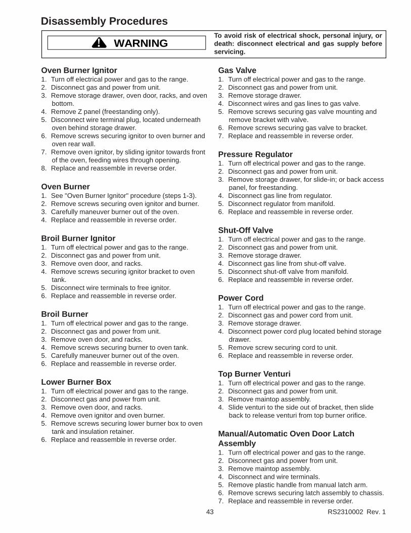
43 RS2310002 Rev. 1
Disassembly Procedures
WARNING!To avoid risk of electrical shock, personal injury, ordeath: disconnect electrical and gas supply beforeservicing.
Gas Valve1. Turn off electrical power and gas to the range.2. Disconnect gas and power from unit.3. Remove storage drawer.4. Disconnect wires and gas lines to gas valve.5. Remove screws securing gas valve mounting and
remove bracket with valve.6. Remove screws securing gas valve to bracket.7. Replace and reassemble in reverse order.
Pressure Regulator1. Turn off electrical power and gas to the range.2. Disconnect gas and power from unit.3. Remove storage drawer, for slide-in; or back access
panel, for freestanding.4. Disconnect gas line from regulator.5. Disconnect regulator from manifold.6. Replace and reassemble in reverse order.
Shut-Off Valve1. Turn off electrical power and gas to the range.2. Disconnect gas and power from unit.3. Remove storage drawer.4. Disconnect gas line from shut-off valve.5. Disconnect shut-off valve from manifold.6. Replace and reassemble in reverse order.
Power Cord1. Turn off electrical power and gas to the range.2. Disconnect gas and power cord from unit.3. Remove storage drawer.4. Disconnect power cord plug located behind storage
drawer.5. Remove screw securing cord to unit.6. Replace and reassemble in reverse order.
Top Burner Venturi1. Turn off electrical power and gas to the range.2. Disconnect gas and power from unit.3. Remove maintop assembly.4. Slide venturi to the side out of bracket, then slide
back to release venturi from top burner orifice.
Manual/Automatic Oven Door LatchAssembly1. Turn off electrical power and gas to the range.2. Disconnect gas and power from unit.3. Remove maintop assembly.4. Disconnect and wire terminals.5. Remove plastic handle from manual latch arm.6. Remove screws securing latch assembly to chassis.7. Replace and reassemble in reverse order.
Oven Burner Ignitor1. Turn off electrical power and gas to the range.2. Disconnect gas and power from unit.3. Remove storage drawer, oven door, racks, and oven
bottom.4. Remove Z panel (freestanding only).5. Disconnect wire terminal plug, located underneath
oven behind storage drawer.6. Remove screws securing ignitor to oven burner and
oven rear wall.7. Remove oven ignitor, by sliding ignitor towards front
of the oven, feeding wires through opening.8. Replace and reassemble in reverse order.
Oven Burner1. See "Oven Burner Ignitor" procedure (steps 1-3).2. Remove screws securing oven ignitor and burner.3. Carefully maneuver burner out of the oven.4. Replace and reassemble in reverse order.
Broil Burner Ignitor1. Turn off electrical power and gas to the range.2. Disconnect gas and power from unit.3. Remove oven door, and racks.4. Remove screws securing ignitor bracket to oven
tank.5. Disconnect wire terminals to free ignitor.6. Replace and reassemble in reverse order.
Broil Burner1. Turn off electrical power and gas to the range.2. Disconnect gas and power from unit.3. Remove oven door, and racks.4. Remove screws securing burner to oven tank.5. Carefully maneuver burner out of the oven.6. Replace and reassemble in reverse order.
Lower Burner Box1. Turn off electrical power and gas to the range.2. Disconnect gas and power from unit.3. Remove oven door, and racks.4. Remove oven ignitor and oven burner.5. Remove screws securing lower burner box to oven
tank and insulation retainer.6. Replace and reassemble in reverse order.
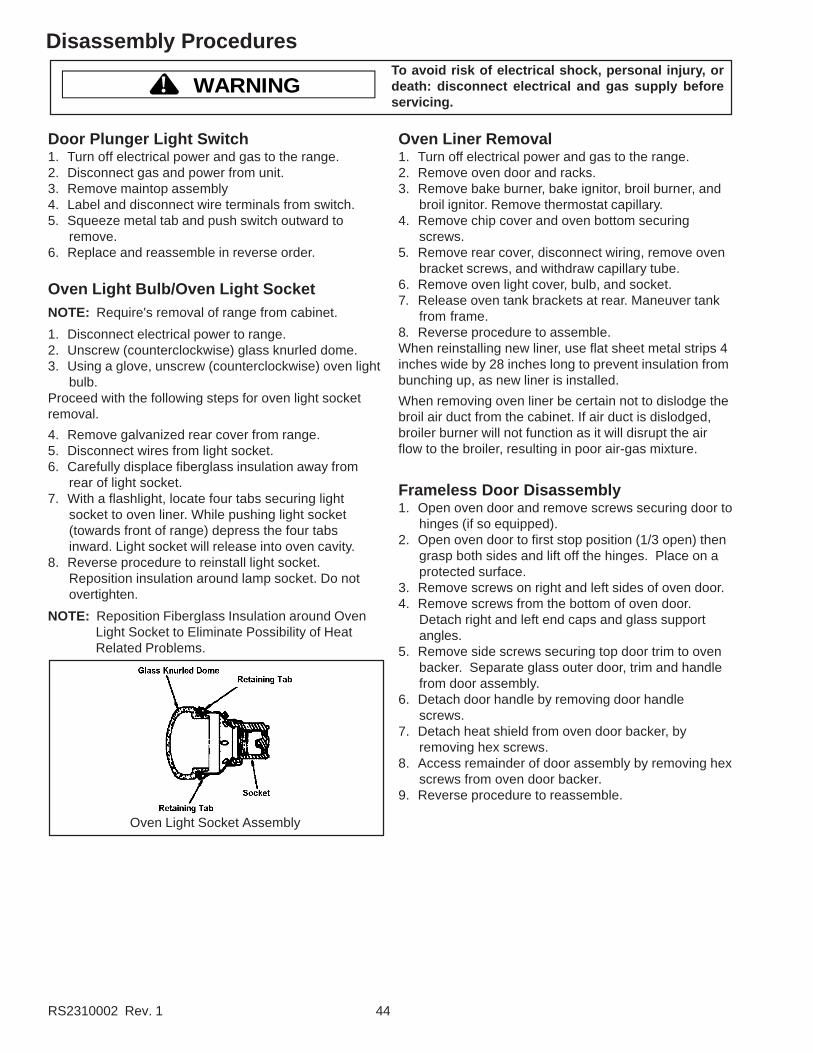
RS2310002 Rev. 1 44
Disassembly Procedures
WARNING!To avoid risk of electrical shock, personal injury, ordeath: disconnect electrical and gas supply beforeservicing.
Door Plunger Light Switch1. Turn off electrical power and gas to the range.2. Disconnect gas and power from unit.3. Remove maintop assembly4. Label and disconnect wire terminals from switch.5. Squeeze metal tab and push switch outward to
remove.6. Replace and reassemble in reverse order.
Oven Light Bulb/Oven Light SocketNOTE: Require's removal of range from cabinet.
1. Disconnect electrical power to range.2. Unscrew (counterclockwise) glass knurled dome.3. Using a glove, unscrew (counterclockwise) oven light
bulb.Proceed with the following steps for oven light socketremoval.
4. Remove galvanized rear cover from range.5. Disconnect wires from light socket.6. Carefully displace fiberglass insulation away from
rear of light socket.7. With a flashlight, locate four tabs securing light
socket to oven liner. While pushing light socket(towards front of range) depress the four tabsinward. Light socket will release into oven cavity.
8. Reverse procedure to reinstall light socket.Reposition insulation around lamp socket. Do notovertighten.
NOTE: Reposition Fiberglass Insulation around OvenLight Socket to Eliminate Possibility of HeatRelated Problems.
Oven Light Socket Assembly
Oven Liner Removal1. Turn off electrical power and gas to the range.2. Remove oven door and racks.3. Remove bake burner, bake ignitor, broil burner, and
broil ignitor. Remove thermostat capillary.4. Remove chip cover and oven bottom securing
screws.5. Remove rear cover, disconnect wiring, remove oven
bracket screws, and withdraw capillary tube.6. Remove oven light cover, bulb, and socket.7. Release oven tank brackets at rear. Maneuver tank
from frame.8. Reverse procedure to assemble.When reinstalling new liner, use flat sheet metal strips 4inches wide by 28 inches long to prevent insulation frombunching up, as new liner is installed.
When removing oven liner be certain not to dislodge thebroil air duct from the cabinet. If air duct is dislodged,broiler burner will not function as it will disrupt the airflow to the broiler, resulting in poor air-gas mixture.
Frameless Door Disassembly1. Open oven door and remove screws securing door to
hinges (if so equipped).2. Open oven door to first stop position (1/3 open) then
grasp both sides and lift off the hinges. Place on aprotected surface.
3. Remove screws on right and left sides of oven door.4. Remove screws from the bottom of oven door.
Detach right and left end caps and glass supportangles.
5. Remove side screws securing top door trim to ovenbacker. Separate glass outer door, trim and handlefrom door assembly.
6. Detach door handle by removing door handlescrews.
7. Detach heat shield from oven door backer, byremoving hex screws.
8. Access remainder of door assembly by removing hexscrews from oven door backer.
9. Reverse procedure to reassemble.

45 RS2310002 Rev. 1
Disassembly Procedures
WARNING!To avoid risk of electrical shock, personal injury, ordeath: disconnect electrical and gas supply beforeservicing.
13.Move rear of side panel away from range then moveside panel forward to clear flange.
14.Reverse procedure to reinstall side panel.
Storage Drawer and Storage Drawer PanelRemoval1. Pull drawer straight out to first stop. Lift front and pull
out to second stop.2. Let front of door rest on floor. Place hands toward
back of drawer and lift it out.
3. To replace:a. Place the set of rollers on the drawer behind the
set of rollers on the oven. (As shown below.)b. Align the guides and push the drawer back into
position.
Storage Drawer Track Removal1. Remove the storage drawer by pulling it out to the
fully open or stop position, lifting the drawer at therear to disengage the drawer track rollers from thedrawer runners, and sliding the drawer out of therange.
2. The tracks are mounted to a rear support and theframe of the range. Remove the two track mountingscrews and remove the track. If the track support isbeing replaced, remove the mounting screw securingit to the side frame and remove the support.
Oven Door Hinge1. Turn off electrical power to range.2. Remove oven door assembly from the range,
remove screws securing oven door to hinges if soequipped.
3. Carefully open the hinge fully, and insert a woodendowel or screwdriver bit into opening marked A onthe following diagram.
4. Remove the top and bottom screws securing hingeassembly to the front frame.
5. Slide the hinge assembly up and move top of hingetowards rear of the range. Withdraw hinge assemblythrough the frame opening.
6. Reverse procedure to reinstall oven door hingeassembly.
Side Panel RemovalNOTE: Replace left or right side panel one at a time. Do
not attempt to remove both side panels as lackof support may cause subsequent damage/twistto backguard.
1. Turn off power to unit.2. Disconnect electrical power and gas line from range.3. Remove oven door assembly.4. Remove storage drawer assembly.5. Remove maintop.6. Remove lower rear galvanized cover from appliance.7. Support side of range four to six inches off floor.
Remove four screws from bottom flange of sidepanel.
8. Remove main top support rod on side beingrepaired, if applicable.
9. Remove screws securing side panel to rearinsulation retainer.
10.Remove screws securing backguard support to sidepanel.
11. Remove screws securing drip baffle to side panel.12.Remove screws securing side panel to front frame
flange.

RS2310002 Rev. 0 46
This page intentionally left blank.

Appendix

A–1 RS2310002 Rev. 1
Clean Timer with Mylar Overlay—315568
CLOCK
TIMER
HOUR
MINUTECLEANSTART
CLEANCANCEL
Clean Timer/Clock Pads and LightsHOUR
• Use when setting hours for timer and clock.
MINUTE• Use when setting minutes for timer and clock.
CLOCK• Use to set time of day.
TIMER• Use to set timer.
CLEAN START• Use to begin self-cleaning.
CLEAN CANCEL• Use to stop self-cleaning.
Self-clean indicator light• Located between CLEAN START pad and
CLEAN CANCEL pad.• Glows when oven is
self-cleaning.
Oven indicator light• Located below clock.• Glows when oven cavity is warming.
This Clean Timer/Clock will NOT delay bake or timebake.
Setting Electronic Clock1. Press CLOCK pad.2. Press MINUTE pad until correct minutes display.3. Press HOUR pad until correct time displays.
• Clock saves time of day after time is entered.• 12 hour clock.
Setting Electronic Timer1. Press TIMER pad.
• 59 minutes displays.• Set timer up to 1 hour 59 minutes.
2. Press MINUTE or HOUR pad to set time.• If desired time is less than 1 hour, press MINUTE
pad until desired time displays.• If desired time is more than 1 hour, press HOUR
pad and then press MINUTE pad until desiredtime displays.
• Timer begins counting down automatically aftertime is entered.
3. After time elapses, press CLOCK pad to cancelsignal and return to time of day.

RS2310002 Rev. 1 A–2
Baking1. Open oven door to confirm nothing is stored in oven
cavity and set racks to proper height.2. To preheat oven, turn oven thermostat knob to
desired temperature . See knob below.• Oven indicator light glows.• When indicator light turns off, oven has reached
desired temperature. During cooking, indicatorlight turns off and on when oven cycles to maintaintemperature.
• For delicate baking allow oven to cycle at least 2times.
3. Place food in oven.4. After cooking time elapses, remove food and turn
oven thermostat knob to “OFF”.
Thermostat Knob
Broiling
WARNING!To avoid risk of fire, do not line the broiler grid withfoil.• Foil may trap grease on top of grid close to burner
causing a fire.• Never leave oven unattended while broiling.
Overcooking may result in a fire.
Broiling Tips• Remove excess fat from meat before broiling. Cut
edges of meat to prevent curling.• Place food on a cold ungreased broiling pan. If pan is
hot, food sticks.• Fish sould be broiled with skin side down. All food
except fish should be turned at least one time. Beginbroiling with skin side down.
• Season meat after it has browned.• Broiling does not require preheating.• If food is not browned enough, cook on a higher rack
position. If food is too browned, cook on a lower rackposition.
1. Center food on broiling grid and pan, and place inoven.
2. Turn oven thermostat knob to BROIL.• Oven indicator light glows.
3. After broiling, remove food and turn oven thermostatknob to OFF.
Self-Cleaning
CAUTION!To avoid risk of personal injury, do not touch ovenvents or areas around vents during self-cleaning.These areas can become hot enough to cause burns.
• A small amount of smoke is normal when cleaning.Excessive smoke may indicate there is a faulty gasketor too much food residue has been left in oven. Movebirds and small animals susceptible to fumes orsmoke to another room.
• Oven should be cleaned before it gets too dirty. Wipeup large spills before self-cleaning.
• Do not use cleaning cycle if oven light cover is notproperly in place.
1. Prepare oven for self-cleaning.
WARNING!To avoid risk of smoke damage or fire, clean excessspills from oven interior.
• Remove oven racks and all cooking utensils fromoven.
• Clean excess spills from oven interior.• Remove items from range top and backguard.
These areas can become hot during self-cleaningcycle.
2. Move oven door lever located above oven door toright to lock oven door.
Unlocked Locked
3. Turn oven thermostat knob to CLEAN position.4. Press CLEAN START pad.
• Self-clean and oven indicator light glow. If ovenindicator does not glow check oven door lever.
• Self-clean cycle lasts for approximately 3½ hours.After 3½ hours oven turns off. There is no signalat the end of cleaning cycle.
5. Turn oven thermostat knob to OFF position whenfinished.• After oven has cooled, door can be unlocked and
opened.• To aviod damaging door lock, do not force lever to
unlocked position.
Interrupt Self-Clean Cycle1. Push CLEAN CANCEL pad and turn oven thermostat
knob to OFF position.2. When oven has cooled to a safe temperature, unlock
and open oven door. Do not force handle, damagewill occur to latch mechanism. If handle will not openallow 1/2 hour for cool down and try again.
Programming Instructions

A–3 RS2310002 Rev. 1
Service InformationThe LED Clock with Minute and Clean Timer is designedto provide clock and timer functions as well as a timedrelay for cleaning operation. This clock consists of adisplay, relay, and all cicuitry which are housed in asingle component.
Functions for the clean cycle to operate correctly consistof latch switch, clock, and thermostat to work in serieswith each other to operate the clean cycle. If one of thecomponents is not operating correctly, this will effect theoperation of cleaning cycle.
Test ProcedurePerformance of this clock is very simple to verify properoperation. Follow the procedures below:
Clock Display Not Operating1. Verify voltage is present at Line 1 and Line 2
terminals of the clock.2. If no voltage is present, verify wire connection are
properly in place, and check wire continuity.3. Replace clock if voltage is present at clock and no
display is present.
Clean Operation of Clock1. Verify voltage to AT3. If no voltage check latch switch
operation, and thermostat operation..2. Verify voltage at AT4 when programmed for clean. If
no voltage, replace the clock.
Testing ProceduresTTTTTo ao ao ao ao avvvvvoid the risk of electric shocoid the risk of electric shocoid the risk of electric shocoid the risk of electric shocoid the risk of electric shoc k,k,k,k,k, per per per per personal injursonal injursonal injursonal injursonal injur y or death,y or death,y or death,y or death,y or death, disconnect po disconnect po disconnect po disconnect po disconnect po werwerwerwerwerbefore servicing, unless testing requires it.before servicing, unless testing requires it.before servicing, unless testing requires it.before servicing, unless testing requires it.before servicing, unless testing requires it.
Refer to wiring diagram for thermostat switch schedule.
AT4 AT3
LINE 1(L) LINE 2(N)
GROUND

B–1 RS2310002 Rev. 1
Electric Slew ERC3—315569
Mylar Overlay Backguard Glass
OVENCANCEL
TIMERON/OFF CLOCK STOP
TIMECOOK TIME
CLEAN BROIL BAKE
DELAYOVEN ONCLEANSTOPTIME
BAKECLEAN
BROILLOCK
ON
OVENCANCEL
TIMERON/OFF
CLOCK STOPTIME
COOK TIME
CLEAN INSTA-BROIL
BAKE
DELAYOVEN ONCLEANSTOPTIME
BAKECLEAN
BROILLOCK
ON
Electronic Oven ControlOVEN CANCEL
• Cancels any cooking or cleaning function excepttimer.
TIMER ON/OFF• Use to time any kitchen function or cancel timer.• Does not control bake, broil, or clean function.
CLOCK• Use to set time of day.
STOP TIME• Use to set delayed or timed bake, and self-clean.
COOK TIME• Use to set delayed or timed bake.
CLEAN• Use to select self-clean cycle.
BROIL/INSTA-BROIL• Use to select broil.
BAKE• Use to select bake.
SLEW or • Use to set temperature or time.
Special Oven Control Functions
Timer SignalWhen time elapses timer beeps 3 times then once every6-8 seconds.
Preheat SignalAfter setting oven to bake and selecting a temperature,oven preheats. When oven reaches set temperature,signal sounds for approximately 1 second.
End of Cycle SignalWhen a timed cooking or cleaning cycle is complete,three long signals sound. Oven signal sounds 3 times,then approximately once every 3 seconds for 5 minutesor until OVEN CANCEL pad is pressed.
If minute timer end of cycle signal is sounding pushTIMER ON/OFF pad.
Child Lock OutThis is a safety feature that can be used to preventchildren from accidently programming the oven. Itdisables the electronic oven control. Touch and holdBAKE and CLOCK for 5 seconds. “OFF” will displaywhere the temperature normally appears.
To reactivate the control, touch and hold BAKE andCLOCK for 5 seconds. Child lockout features must bereset after a power failure.
12 Hour Automatic CancelThis is a safety feature that prevents oven fromcontinuing to operate if it has been left on for over 12hours. If a cooking function continues longer than 12hours without any options on oven control beingtouched, this feature turns oven off. Any time an optionis touched, 12 hour automatic cancel is reset.
Increasing Slew Pad Speed or When setting time and temperature, hold pad toaccelerate the rate at which the numbers increase ordecrease.
Self-Diagnostic SystemElectronic range control has a self-diagnostic system.Self-diagnostic system sounds a series of short, rapidbeeps and shows a “F-code” in display when there is aproblem.

RS2310002 Rev. 1 B–2
Programming Instructions
Quick Reference InstructionsRead “Important Safety Information” before using “QuickReference Instructions”. If there are unansweredquestions, refer to detailed sections of this manual.
Flashing DisplayWhen power is connected to range, numbers flash inelectronic range control. Press OVEN CANCEL pad tostop flashing.
Setting Clock12 hour clock does not display a.m., p.m., or militarytime.
1. Press CLOCK pad.• “TIME” displays.
2. Press or pad until correct time of day isdisplayed.
3. Press OVEN CANCEL pad to set time.• If OVEN CANCEL pad is not pressed,
approximately 30 seconds after last entry, “TIME”disappears and time is set.
Setting Minute TimerTimer can be used while another feature is in use.
1. Press TIMER ON/OFF pad.• “TIMER” displays.
2. Press or pad until desired amount of time isdisplayed.• Timer can be set from 5 seconds to 9 hours and
50 minutes.• Timer begins counting down automatically.
3. When time elapses timer beeps 3 times thenapproximately once every 6-8 seconds.• Press TIMER ON/OFF to cancel beep but remain
in timer mode.
Canceling Minute TimerPress TIMER ON/OFF pad for 3 seconds.
• When canceling minute timer do not press OVENCANCEL pad. Pressing OVEN CANCEL pad cancelscooking function.
Baking or Broiling1. Press BAKE or BROIL pad.2. Press or pad until desired temperature or
broiler setting is displayed.3. Oven begins baking or broiling automatically.
Canceling Bake or BroilPress OVEN CANCEL pad.
Self-Cleaning1. Remove oven racks and all utensils from oven and
range top. Clean excess spills from oven.
2. Press CLEAN pad, 3 hour time in display.
3. Press or pad to adjust clean time. Clean canbe set from 2 to 4 hours.
4. Oven begins cleaning automatically.
Canceling Self-Cleaning Cycle1. Press OVEN CANCEL pad.2. When oven has cooled to a safe temperature, door
will unlock.• When “LOCK” no longer displays, oven
temperature is safe. Do not force door while“LOCK” displays.
BakingOpen oven door to confirm nothing is stored in ovencavity and set racks to proper height before baking. Formost recipes, preheat oven before placing food insideoven. To bake delicate food items, like pastries, preheatoven for an additional 10-15 minutes after preheatsignal. Pans must be staggered for even browning.
1. Press BAKE pad.• “BAKE” and “---°” display.
2. Press or pad until desired temperature isdisplayed.• Temperature begins at 350°F and can be set from
170°F to 550°F in 5 degree increments.• Time of day, oven temperature, “BAKE”, and “ O
N ”display.
• Temperature starts at 100°F and increases in 5°increments until reaching set temperature. Someminor smoking is normal when using oven for firsttime.
• When cook temperature is reached preheat signalsounds.
3. Press OVEN CANCEL pad when finished.• Remove food from oven when cooking time has
elapsed. Food left in oven can overcook.

B–3 RS2310002 Rev. 1
Programming InstructionsTimed Baking1. Place food in oven.2. Press COOK TIME pad.
• “OVEN”, “TIME”, “HR”, and “0:00” display.3. Press or pad until cooking time is displayed.
• “TIME”, “BAKE”, and “HR” display. “HR” does notdisplay if less than an hour of time is set.
• Cook time can be set up to 11 hours and 55minutes.
• 10 minutes minimum cooking time.• If cook time is entered and temperature not
entered “BAKE” flashes and oven signals.4. Press BAKE pad.
• “BAKE” and “---°” display.5. Press or pad until desired temperature is
displayed.• “OVEN”, “TIME”, “BAKE”, “ O
N ”, and “HR” display.• Cooking time begins to count down.• Temperature begins at 350°F and can be set from
170°F to 550°F in 5°F increments.• Temperature display increases in 5°F increments
starting at 100°F until reaching set temperature.Some minor smoking is normal when using ovenfor first time. When cook temperature is reachedoven signals.
• Preheat signal sounds when oven cavity reachestemperature.
• When cooking time has elapsed, an end-of-cyclesignal sounds, oven automatically turns off anddisplay returns to time of day.
6. Press OVEN CANCEL pad when finished.• Remove food from oven when cooking time has
elapsed. Food left in oven can overcook.• Pressing OVEN CANCEL stops end of cycle
signal.
To Cancel Remaining Cooking TimePress OVEN CANCEL pad.
Delayed Baking
CAUTION!To reduce the risk of food poisoning, never hold meat,milk, fish, or eggs for more than 2 hours beforecooking.
1. Place food in oven.2. Press BAKE pad.
• “BAKE” and “---°” display.3. Press or pad until desired temperature is
displayed.• Temperature begins at 350°F and can be set from
170°F to 550°F in 5 degree increments.• Time of day, oven temperature, “BAKE”, and “ O
N ”display.
4. Press STOP TIME pad.• Current time of day, “STOP”, “TIME”, “BAKE”, and
“ ON ” display.
5. Press or pad until desired stop time displays.• Stop time can be set up to 11 hours 55 minutes
ahead of current time of day.6. Press COOK TIME pad.
• “OVEN”, “TIME”, and “BAKE” display.• To view cook time later, press COOK TIME pad.
7. Press or pad until desired cooking timedisplays.• Maximum cooking time, “DELAY”, “OVEN”,
“TIME”, “HR”, and “BAKE” display.• When start time is reached “DELAY” no longer
displays and “ ON ” displays.
• 10 minutes minimum cooking time.• Electronic range control calculates start time.• To view cook time, press COOK TIME pad.• When cooking time has elapsed, end-of-cycle
signal sounds, oven automatically turns off anddisplay returns to time-of-day.
• Press OVEN CANCEL to stop end of cycle signal.
To Cancel Remaining Cooking TimePress OVEN CANCEL pad.

RS2310002 Rev. 1 B–4
Programming InstructionsBroilingPreheating is not required when using broil.
WARNING!• To avoid risk of fire, do not line the broiler grid with
foil. Foil may trap grease on top of grid close toelement causing a fire.
• Never leave oven unattended while broiling.Overcooking may result in a fire.
• Oven door must be closed while broiling.• Remove excess fat from meat before broiling. Cut
edges of meat to prevent curling.• Place food on a cold ungreased broiling pan. If pan is
hot, food sticks.• Season meat after it has browned.• Begin cooking using suggested rack levels in “Broiling
Guide” section to test broiler results. If food is notbrowned enough, cook on a higher rack position. Iffood is too browned, cook on a lower rack position.
• All foods should be turned at least once except fish,which does not need to be turned.
1. Center food on broiling grid and pan, and place inoven.• Oven door must be closed while broiling.
2. Press BROIL pad.• “BROIL” and “---” displays.
3. Press or .• Oven begins to broil automatically. “BROIL”, “ O
N ”,and “HI” display.
4. Press OVEN CANCEL pad when finished.
Self-Cleaning• A small amount of smoke is normal when cleaning.
Excessive smoke may indicate too much food residuehas been left in oven or a failed gasket .
• Clean oven before it gets too dirty. Wipe up large spillsbefore self-cleaning.
• Do not use cleaning cycle if oven light cover is notproperly in place.
WARNING!To avoid risk of smoke damage or fire, clean excessspills from oven interior and under oven bottombefore self-cleaning range. Wear hand protection toavoid injury from sharp edges.1. Pull oven bottom forward and lift out of range.2. Wipe out burner area with a cloth and warm
soapy water.3. Dry area thoroughly and replace oven bottom.
CAUTION!To avoid risk of personal injury, do not touch ovenvents or areas around vents during self-cleaning.These areas can become hot enough to cause burns.
1. Prepare oven for self-cleaning.• Remove oven racks and cooking utensils from
oven.• Clean excess spills from oven interior.• Remove items from range top and backguard.
These areas can become hot during self-cleaningcycle.
2. Press CLEAN pad.• “CLEAN”, “TIME”, and “----” display.
3. Press or pad to adjust cleaning time.• “3:00” displays when or is pressed.• Increase or decrease cleaning time by 5 minute
increments.• Clean can be set from 2 to 4 hours. Minimum
recommended cleaning time is 3 hours.• Oven begins to clean. “HR”, “CLEAN, “TIME”,
“CLEAN”, “LOCK”, and “ ON ” lights. “LOCK” flashes
in display when automatic door latch is locking.• When cleaning time has elapsed, oven
automatically turns off and display returns totime-of-day. Ther is no signal end of clean cycle.
• When oven cools to a safe temperature, door latchopens and “LOCK” light flashes while opening.After door latch opens, “LOCK” light no longerdisplays and door can be opened.
Interrupt Self-Clean Cycle1. Press OVEN CANCEL pad.2. When oven has cooled to a safe temperature, door
will unlock and can be opened.Delayed Self-Cleaning
Delayed Self-Cleaning• A small amount of smoke is normal when cleaning.
Excessive smoke may indicate there is a faulty gasketor too much food residue has been left in oven.
• Clean oven before it gets too dirty. Wipe up large spillsbefore self-cleaning.
• Do not use cleaning cycle if oven light cover is notproperly in place.
WARNING!To avoid risk of smoke damage or fire, clean excessspills from oven interior and under oven bottombefore self-cleaning range. Wear hand protection toavoid injury from sharp edges.1. Pull oven bottom forward and lift out of range.2. Wipe out burner area with a cloth and warm
soapy water.3. Dry area thoroughly and replace oven bottom.

B–5 RS2310002 Rev. 1
Programming Instructions
CAUTION!To avoid risk of personal injury, do not touch ovenvents or areas around vents during self-cleaning.These areas can become hot enough to cause burns.
1. Prepare oven for self-cleaning.• Remove oven racks and all cooking utensils from
oven.• Clean excess spills from oven interior.• Remove items from range top and backguard.
These areas can become hot during self-cleaningcycle.
2. Press CLEAN pad.• “CLEAN”, “TIME”, and “----” display.
3. Press or pad until desired amount of cleaningtime is displayed.• “3:00” displays when or is pressed.• Increase or decrease cleaning time in 5 minute
increments.• Clean can be set from 2 to 4 hours. Minimum
recommended cleaning time is 3 hours.4. Press STOP TIME pad.5. Press or pad until desired stopping time
appears in display.• Starting time is automatically calculated based on
amount of cleaning time and stop time.• “DELAY”, “CLEAN, “STOP”, “TIME”, “CLEAN”,
and “LOCK” display. “LOCK” flashes in displaywhen automatic door latch is locking.
• To view remaining cleaning time, press and holdCLEAN pad.
• To view calculated stop time, press STOP TIMEpad.
• When cleaning time has elapsed, ovenautomatically turns off and display returns totime-of-day.
• When oven cools to a safe temperature, doorlatch opens and “LOCK” light flashes whileopening. After door latch opens, “LOCK” light nolonger displays and door can be opened.
Interrupt Self-Clean Cycle1. Press OVEN CANCEL pad.2. When oven has cooled to a safe temperature, door
will unlock and can be opened.
Child Lock OutThis feature disables oven control. Surface elements canbe used while child lock out is on.
1. Press and hold BAKE and CLOCK padssimultaneously.• “OFF” displays briefly.
2. Repeat step 1 to cancel child lock.
Adjusting Oven TemperatureOven temperature has been factory calibrated andtested.
If oven consistently over or under cooks food, adjusttemperature offset. Oven temperature can be increasedor decreased 35°F. To avoid over adjusting oven, movetemperature 5°F each time.
1. Push BAKE pad.2. Press pad until an oven temperature greater than
500°F shows in display.3. Immediately push and hold, approximately
5 seconds, BAKE button until “00” appears indisplay.
4. Press or pad knob to adjust oventemperature.• To increase oven temperature (for a hotter oven),
Press or pad until a positive numberappears in display.
• To decrease oven temperature (for a cooler oven),Press or pad until a negative numberappears in display.
5. Press OVEN CANCEL pad to save adjustment.• Setting is saved if power fails or is disconnected.
Service Tones and CodesElectronic range control has a self-diagnostic system.Self-diagnostic system sounds a series of short, rapidbeeps and shows a “F-code” in display when there is aproblem. When electronic range control signals aproblem, follow steps listed below.1. Record “F-code” shown.
• F1—pad malfunction• F2—high oven temperature• F3—temperature sensor malfunction• F4—temperature circuit malfunction• F5—control malfunction• F7—door lock malfunction• F9—door lock or oven door not completely closedDoor—door not closed/malfuction in door switch
circuit or latch switch“Lock”–flashing—malfuction in door switch or lock
switch ciruit2. Press TIMER ON/OFF pad or disconnect electrical
supply.• Disconnecting electrical supply eliminates
“F-code”. If failure continues, contact an authorizedservicer.
3. Contact an authorized servicer to check range.

RS2310002 Rev. 1 B–6
Testing ProceduresTTTTTo ao ao ao ao avvvvvoid the risk of electric shocoid the risk of electric shocoid the risk of electric shocoid the risk of electric shocoid the risk of electric shoc k,k,k,k,k, per per per per personal injursonal injursonal injursonal injursonal injur y or death,y or death,y or death,y or death,y or death, disconnect po disconnect po disconnect po disconnect po disconnect po werwerwerwerwerbefore servicing, unless testing requires it.before servicing, unless testing requires it.before servicing, unless testing requires it.before servicing, unless testing requires it.before servicing, unless testing requires it.
Service InformationThe ERC consist's of a display, relays and all circuitryhoused in a Lexan enclosure.
The ERC has eight function pads oven cancel, timer on/off, clock, stop time, cook time, clean, broil, bake, andtwo slew pads to select time and temperature.
The oven temperature sensor is mounted in the ovencavity and is connected to the J2-1 and J2-2 connectorson the rear of the ERC. As the oven temperatureincreases, the sensor resistance also increases. TheERC converts this resistance change to a correspondingtemperature readout and to cycle the bake/broil relays tomaintain the desired temperature setting.
The ERC is also capable of sensing certain failureconditions which can occur in the temperature sensor,the self-clean latch switch or the ERC itself. If the ERCsenses a failure, power will be removed from the bake/broil relays, an alarm will sound, and a failure code willbe displayed.
Each major component of the Electronic Range ControlSystem (ERC control board, and temperature sensor) isserviced as a separate part. However, each componentand related wire harness must be tested prior toreplacing an individual component.
Control will automatically cancel any cooking operationand remove all relay drives twelve hours after mode wasinitiated if user forgets to cancel it or no input is made.This model is not equipped with child lock outprogramming.
Testing Procedures
'Quick Test' Mode for Electronic Range ControlFollow procedure below to use the quick test mode.Entries must be made within 32 seconds of each otheror the control will exit the quick test mode. The quicktest mode cannot be reactivated until power isdisconnected from the oven.
1. Apply power to oven press and hold COOK TIMEpad for 5 seconds within the first 5 minutes of powerup. (This must be the first pad/button pressed).
2. Test mode functions are accessed by pressing andholding down individual pads to activate. Activationof the pad will stop when the pad is released.
Pad ResponseBAKE Energizes bake relayBROIL/ Energizes broil relayINSTA-BROILCLEAN 3 represents lock and unlock
contacts closed - invalid2 represents lock contacts closed, unlock contacts open1 represents lock contacts open, unlock contacts closed0 represents both contacts open -
invalidSTOP TIME Beeper on and micro ID numberTIMER Last time of day displayedCLOCK All display segments liteCOOK TIME Displays checksum and sensor
temperatureSLEW PADS Sequences through display
segmentCANCEL Exits quick test mode
If relays do not "click" when Bake or Broil pads arepressed, replace the ERC.
If other function's do not perform as specified, replace theERC.
ERC Warnings and Failure CodesThe Electronic Range Control is capable of detectingcertain failures within the ERC, the oven temperature

B–7 RS2310002 Rev. 1
sensor and the self-clean latch switch.
The failure codes and warnings which may appear on thedisplay are listed below. A brief description of the failurecodes is also listed:
DIGIT FAILURE DISPLAYF1- A shorted input pad/button.
Verify function pad/buttons are not binding on controlpanel glass. Reposition glass and/or the ERC. Make surebuttons spring outward after being depressed.
F2- Oven cavity over temperature.Check sensor resistance, wiring harness and connections.
F3- Open circuit in oven temperature sensor circuit.Check sensor resistance, wiring harness and connections.
F4- Shorted circuit in oven temperature sensor circuit.Check sensor resistance, wiring harness and connections.
F5- Defective watchdog circuit in control.Check all components and wiring prior to replacing theERC.
F7- Failure of door lock switch sensing with door locked.Check latch switch, door motor, and wiring.
F9- Failure of door lock switch sensing with door unlocked.Check latch switch, door motor, and wiring.
Door- door not closed/malfuction in door switchcircuitor latch switch
“Lock”-flashing malfuction in door switch or lockswitch ciruit
Testing ProceduresTTTTTo ao ao ao ao avvvvvoid the risk of electric shocoid the risk of electric shocoid the risk of electric shocoid the risk of electric shocoid the risk of electric shoc k,k,k,k,k, per per per per personal injursonal injursonal injursonal injursonal injur y or death,y or death,y or death,y or death,y or death, disconnect po disconnect po disconnect po disconnect po disconnect po werwerwerwerwerbefore servicing, unless testing requires it.before servicing, unless testing requires it.before servicing, unless testing requires it.before servicing, unless testing requires it.before servicing, unless testing requires it.
Temperature SensorSensor resistance may be checked by removing thesensor interconnect plug from the ERC J2 connector andinserting ohmmeter leads into the harness connectorplug (pin one and two). Refer to the appropriate wiringdiagram/schematic for exact pin placement and colorcoding. A resistance reading of approximately 1075ohms should be indicated at room temperature (75degrees F). If a higher resistance is indicated, disconnectwire harness from sensor and recheck sensor resistanceto verify the failure is in sensor and not in wire harness orconnections. The following list gives correspondingresistance for different oven temperatures.
ApproximateTemperature Sensor Resistance75 degrees F 1075 ohms350 degrees F 1625 ohms550 degrees F 2025 ohms880 degrees F 2675 ohms
Replace sensor if it does not meet these specifications.

C–1 RS2310002 Rev. 1
Eaton KRC with Mylar Overlay
SELF CLEAN OVEN
OFF
LO HI
MED REAR FRONT
OFF
LO HI
MED
OFFWM
500
BROIL
250
450
550PREHEATED
OVEN
OFF
LO HI
MED
OFF
LO HI
MED FRONT REAR
OVEN LIGHT
SURFACE400
350
300
200
ditionFirst E
LOCKED
CLEANTIMER
CLOCK
+HRS
+MINS
HRS MINS
TIMER
CLOCK
+HRS
+MINS
HRS MINS
OFF
LO HI
MED REAR FRONT
OFF
LO HI
MED
OFF
WM
500
BROIL
250
450550PREHEATED
OVEN
OFF
LO HI
MED
OFF
LO HI
MED FRONT REAR
OVEN LIGHT
400350
300
200
LOCKED
CLEAN
SELF CLEAN OVEN
B CA DA A A
B CA DA A AB
A Surface elementcontrol knob
Use to turn surface elements on and off. Settings:LO—Use to prepare food at less than boiling temperatures or to simmer.
MED—Use to maintain boiling of larger amounts of food, low temperature frying and tomaintain correct pressure in a pressure cooker.
HI—Use to bring food to boiling temperatures. When food is boiling temperature settingshould be reduced to MED through HI.
B Surface elementindicator light
Some ranges have two indicator lights, one for elements on right side and one forelements on left side of range. When either front or rear element is on, correspondingindicator light glows.
Some ranges have one indicator under clock. When any element is on, indicator lightglows.
Smoothtop ranges can have one or two indicator lights. After the surface controls areturned off, the appropriate surface indicator light will continue to glow until the surfaceelements have cooled. The time each light remains on will vary. Do not expect thelights for two different heating areas to go off at the same time even if the elementswere turned off simultaneously.
C Oven light switch Used to light inside of oven. On some models, light turns on when oven door is opened.On all models, switch located next to clock, turns oven light on and off without openingdoor.
D Range control Used to control oven functions like baking, broiling, and self-clean. Also controls clockand minute timer.

RS2310002 Rev. 1 C–2
Electronic Oven Control Pads and LightsTIMER pad selects timer feature. Timer can be set up to11 hour 59 seconds. Timer does not control ovenoperation. Timer light flashes when timer is being setand glows when timer is counting down. Timer lightallows user to identify timer mode quickly and easily.
CLOCK pad is pressed to set clock and turn clockdisplay on and off.
HRS pads increase or decrease time by hours.
MIN pads increase or decrease time by minutes.
OVEN light glows when oven is on. Light flashes afterself-clean cycle turns off as a reminder to turntemperature knob to OFF.
LOCKED light glows when oven door is locked and ovenis set for self-cleaning. After self-clean cycle,light flashes. Unlatch oven door and turn temperatureknob to OFF.
PREHEATED light glows when oven reaches selectedtemperature.
Temperature knob controls oven temperature, self-clean, and broil. Push-to-turn knob prevents accidentlyturning oven on.
Time display shows the time-of-day and timer minutes.
Setting Electronic ClockElectronic clock has 3 modes—Clock displayed, setclock (flashing), and clock not displayed. Press CLOCKpad to advance through modes.
When power is connected or restored, display flashesuntil pad is pressed or temperature knob is turned.
Reset clock.1. Verify display is flashing.
• If display does not flash, press CLOCK padrepeatedly until display flashes.
2. Press HRS + or - pad to set hours and MINS + or -pad to set minutes.
3. Press CLOCK pad to save time-of-day.• Clock saves time-of-day approximately 60
seconds after time is entered if CLOCK pad is notpressed.
Turning Off/On Clock DisplayPress CLOCK pad until display is blank. Clock retainstime while not displayed. To turn on display, pressCLOCK pad until time-of-day displays and is notflashing.
Setting Electronic TimerThe minute timer is a timer only. Electronic timer doesnot control bake, broil, or self-clean function. Timer canbe set up to 11 hours and 59 minutes.
1. Press TIMER pad.2. Press HRS + or - pad to set hours and MINS + or -
pad to set minutes.• Timer begins counting down automatically after
time is entered.• To view clock while timer counts down, press
CLOCK pad. To view timer again, press TIMERpad.
3. Press TIMER pad again to cancel.
Resetting and Canceling TimerTo reset or cancel timer, display must show remainingtime. If display does not show remaining time, pressTIMER pad.
To reset the time when remaining time is displayed,press the HRS + or - pad to set hours and MINS + or -pad to set minutes until new time displays.
To cancel timer when remaining time is displayed orsignal after time elapses, press TIMER pad.
TIMER
CLOCK
+HRS
+MINS
HRS MINS
OFFWM
500
BROIL
250
450
550PREHEATED
OVEN
400350
300
200
LOCKED
CLEAN
Programming Instructions

C–3 RS2310002 Rev. 1
Automatic Oven ShutoffAs a safety feature, oven control automatically shuts offoven after 12 hours of operation. This feature can beturned on or off.
To allow the oven to operate for more than 12 hours,confirm temperature knob is in OFF position. Then,press and hold the MINS + and - pads forapproximately 4 seconds. Display will change from time-of-day, show “OFF”, and then return to time-of-day..
To set oven to shut off after 12 hours, confirmtemperature knob is in the OFF position. Then, pressand hold the MINS + and - pads for approximately4 seconds. Display will change from time-of-day, show“ON”, and then return to time-of-day.
Quick Reference InstructionsRead “Important Safety Instructions” before using“Quick Reference Instructions”. If there are unansweredquestions, see detailed sections of this manual.
Setting Electronic Clock1. Verify display is flashing.2. Press HRS + or - pad to set hours and MINS + or -
pad to set minutes.3. Press CLOCK pad to save time-of-day.
Turning Off/On Clock DisplayPress CLOCK pad until display is blank. Clock retainstime while not displayed. To turn on display, pressCLOCK pad until time-of-day displays and is notflashing.
Setting Electronic Timer1. Press TIMER pad.2. Press HRS + or - pad to set hours and MINS + or -
pad to set minutes.3. Press TIMER pad again to cancel.
Resetting and Canceling TimerTo reset time when remaining time is displayed, pressthe HRS + or - pad to set hours and MINS + or - pad toset minutes until new time displays.
To cancel timer when remaining time is displayed orsignal after time elapses, press TIMER pad.
Operating Surface Elements1. Push in and turn surface element control to desired
setting.2. When finished cooking, turn control to OFF position.
Baking1. Open oven door to confirm nothing is stored in oven
cavity and set racks to proper height.2. To preheat oven, turn oven temperature knob to
desired temperature.3. Place food in oven.4. After cooking time elapses, remove food and turn
oven temperature knob to OFF.
Adjusting Factory Set Baking Temperature1. Turn oven temperature knob to OFF.2. Press and hold HRS + and HRS - pad for
approximately 5 seconds.3. Immediately, press either Press HRS + or HRS - pad.
• HRS + increases oven temperature by 5°F.• HRS - decreases oven temperature by 5°F.
Broiling1. Center food on broiling grid and pan, and place in
oven.• Oven door should be opened to first stop.
2. Turn oven temperature knob to BROIL.3. After broiling, remove food and turn oven
temperature knob to OFF.
Self-Cleaning1. Prepare oven for self-cleaning.2. With oven door closed, move oven door lever located
above oven door to right to lock oven door.3. Turn oven temperature knob to CLEAN position.
Interrupt Self-Clean Cycle1. Turn oven temperature knob to OFF position.2. When oven has cooled to a safe temperature,
LOCKED light flashes. Door can be unlocked andopened.• Do not force door lever open. If door lever is
forced, lock can be damaged.
After Self-cleaning CycleTurn oven temperature knob to OFF position whenfinished. After oven has cooled LOCKED light flashes.Door can be unlocked and opened.
Programming Instructions

RS2310002 Rev. 1 C–4
Baking1. Open oven door to confirm nothing is stored in oven
cavity and set racks to proper height.2. To preheat oven, turn oven temperature knob to
desired temperature.• Oven indicator light glows if knob is set to any
position but OFF.• When oven reaches desired temperature,
PREHEATED light glows and oven beeps 6 times.3. Place food in oven.
• If self-clean lever is moved to lock position whilebaking, LOCKED light flashes and oven does notheat. Move lever to unlocked position to resumebaking.
4. After cooking time elapses, remove food and turnoven temperature knob to OFF.
OFFWM
500
BROIL
250
450
550PREHEATED
OVEN
400
350
300
200
LOCKED
CLEAN
Temperature Knob
Adjusting Factory Set Baking TemperatureOven temperature is set at factory. When first usingoven, follow recipe times and temperatures. If you thinkoven is too hot or too cool, temperature can be adjusted.Before adjusting oven baking temperature, test a recipeby using a temperature set higher or lower than therecommended temperature. The baking results shouldhelp you to decide how much adjustment is needed.
1. Turn oven temperature knob to OFF.2. Press and hold HRS + and HRS - pad for
approximately 5 seconds.3. Immediately, press either HRS + or HRS - pad.
• HRS + increases oven temperature by 5°F.• HRS - decreases oven temperature by 5°F.• Oven temperature can be changed up to 35°F.
When temperature is adjusted cooler “-” shows indisplay followed by offset temperature.
• After a few seconds control saves new setting andreturns to previous display.
Broiling
WARNING!To avoid risk of fire:• Do not line the broiler grid with foil. Foil may trap
grease on top of grid close to burner causing a fire.• Never leave oven unattended while broiling.
Overcooking may result in a fire.
Broiling Tips• Remove excess fat from meat before broiling. Cut
edges of meat to prevent curling.• Place food on a cold ungreased broiling pan. If pan is
hot, food sticks.• All food except fish should be turned at least one time.
Begin broiling with skin side down.• Season meat after it has browned.• Broiling does not require preheating.• Begin cooking using suggested rack levels in Broiling
Guide section to test broiler results. If food is notbrown enough, cook on a higher rack position. If foodis too brown, cook on a lower rack position.
1. Center food on broiling grid and pan, and place inoven.• Oven door should be opened to first stop or remain
closed.2. Turn oven temperature knob to BROIL.
• Oven indicator light glows.• If self-clean lever is moved to lock position while
broiling and oven door is closed, LOCKED lightflashes and oven does not heat. Move lever tounlocked position to resume broiling.
3. After broiling, remove food and turn oventemperature knob to OFF.
Programming Instructions

C–5 RS2310002 Rev. 1
Self-Cleaning
WARNING!To avoid risk of personal injury, do not touch ovenvents or areas around vents during self-cleaning.These areas can become hot enough to cause burns.
WARNING!To avoid risk of smoke damage or fire, clean excessspills from oven interior.
Prepare for Self-clean Cycle• A small amount of smoke is normal when cleaning.
Excess smoke may indicate a faulty gasket or toomuch food residue has been left in oven. Move birdsand small animals susceptible to fumes or smoke toanother room.
• Oven should be cleaned before it gets too dirty. Wipeup large spills before self-cleaning.
• Do not use cleaning cycle if oven light cover is notproperly in place.
Self-cleaning1. Prepare oven for self-cleaning.
• Remove oven racks and all cooking utensils fromoven.
• Clean excess spills from oven interior.• Remove items from rangetop and backguard.
These areas can become hot during self-cleaningcycle.
2. With oven door closed, move oven door lever locatedabove oven door to right to lock oven door.• If oven is too hot before starting self-clean cycle,
oven lever will not move to locked position. Allowoven to cool before starting cycle.
3. Turn oven temperature knob to CLEAN position.• If oven temperature knob is set before oven door
lever is moved, LOCKED light flashes. Move ovendoor lever to locked position.
• LOCKED and OVEN indicator light glows.• Self-clean cycle lasts for approximately 4 hours.
After self-clean cycle, OVEN and LOCKED lightsflash. Turn temperature knob to OFF position andmove oven door lever to unlocked position.
Interrupt Self-Clean Cycle1. Turn oven temperature knob to OFF position.2. When oven has cooled to a safe temperature,
LOCKED light flashes. Door can be unlocked andopened.• Do not force door lever open. If door lever is
forced, lock can be damaged.
After Self-cleaning CycleTurn oven temperature knob to OFF position whenfinished. After oven has cooled LOCKED light flashes.Door can be unlocked and opened.
Service TonesRange control is equipped with a self diagnostic system.Self diagnostic system will alert you if there is a error orproblem in the control. If electronic range control soundsa series of short, rapid beeps for over 16 seconds anddisplay shows a F-code. Disconnect electrical supply torange and contact an authorized servicer.
Some F-codes can be cleared by disconnecting powerto the range. If code continues to reoccur, record theF-code shown and call an authorized servicer.
Code DescriptionF2—High oven temperature.F3—Temperature sensor.F4—Temperature sensor.FFF—Control failure.
Programming Instructions

RS2310002 Rev. 1 C–6
Testing ProceduresTo avoid risk of electric shock, personal injury or death,disconnect power before servicing, unless testing requires it.
Service InformationThis control consists of a display, relays, and all cicuitrywhich are housed in a single component. The mylaroverlay is not part of the clock assembly, and needs tobe replaced seperately if the unit is replaced.
Components for the clean cycle to operate correctlyconsist of latch switch, control, and temperature sensorwhich work in series with each other to operate theclean cycle. If one of the components is not operatingcorrectly, this will effect the operation of cleaning cycle.
KRC Terminal Idenification Chart
Location ConnectionP2−1 Door lockP2−2 No connectionP2−3 Door lockP2−4 SensorP2−5 SensorP3 LineP4 NeutralP5 BroilP6 Bake
P3P4P5P6
RelaysP2
P11 12
1
WARNING!
Drive Element RequirementsBake
100% bake element
Broil
100% broil element
Clean
Stage 1 Time controlled 30 minutes, 100% broilStage2 Same element control as bake modeTime Total clean time 4 hours with last 30 minutes
for cool down
KRC Warnings and Failure CodesThis control is capable of detecting certain failure withinthe control, oven temperature sensor, and wiring.
The failure codes and warnings which may appear onthe display are listed below. A brief description of thefailure codes are also listed.
DIGITAL FAILURE DISPLAYF2—Oven cavity over temperature.
Check sensor resistance, wiring harness, andconnections.
F3—Open circuit in oven temperature sensor circuit.Check sensor resistance, wiring harness, andconnections.
F4—Shorted circuit in oven temperature sensor circuit.Check sensor resistance, wiring harness, andconnections.
FFF—Control failure.Check all components and wiring prior toreplacing control.

C–7 RS2310002 Rev. 1
Temperature SensorSensor resistance may be checked by removing thesensor interconnect plug from the KRC P2 connectorand inserting ohmmeter leads into the harnessconnector plug (P2–4 and P2–5). Refer to theappropriate wiring diagram/schematic for exact pinplacement and color coding. A resistance reading ofapproximately 1075 ohms should be indicated at roomtemperature (75° F). If a higher resistance is indicated,disconnect wire harness from sensor and rechecksensor resistance to verify the failure is in sensor andnot in wire harness or connections. The following listgives corresponding resistance for different oventemperatures.
ApproximateTemperature Sensor Resistance
75° F 1075 ohms350° F 1625 ohms550° F 2025 ohms880° F 2675 ohms
Replace sensor if it does not meet these specifications.
Test ProcedurePerformance of this clock is very simple. To verifyproper operation, follow the procedures below:
KRC Control not Operating1. Verify 120 VAC is present at P3 (L1) and P4 (NEU)
terminals of the control.2. If no voltage is present, verify wire connection are
properly in place, and check wire continuity.3. Replace control if voltage is present and no display is
present.
NOTE: Press clock pad to verify display is not turnedoff.
Clean Operation of Control1. If no voltage is present, verify wire connections are
properly in place, and check wire continuity.2. If voltage is present and clean function does not
operate.Verify latch switch is operating properly.3. If latch switch is operating properly, verify relay
voltage at terminals, to confirm relay is operatingproperly.
4. If relay is operating, verify temperature sensor isoperating properly.
5. If latch switch and sensor is operating properly, butclean cycle does not operate, replace control.
Testing ProceduresTo avoid risk of electric shock, personal injury or death,disconnect power before servicing, unless testing requires it.WARNING!