service literature g26 series units - complete...
TRANSCRIPT
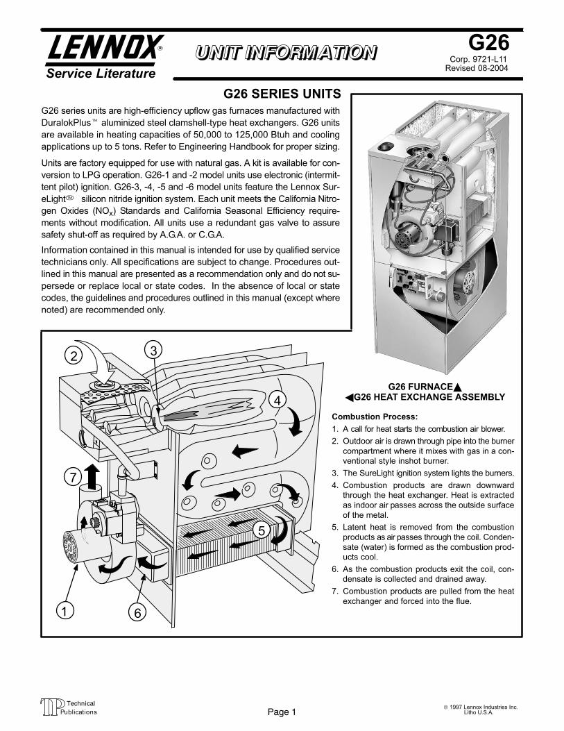
FIGURE 1
G26 FURNACE��G26 HEAT EXCHANGE ASSEMBLY
Combustion Process:
1. A call for heat starts the combustion air blower.
2. Outdoor air is drawn through pipe into the burner
compartment where it mixes with gas in a con-
ventional style inshot burner.
3. The SureLight ignition system lights the burners.
4. Combustion products are drawn downward
through the heat exchanger. Heat is extracted
as indoor air passes across the outside surface
of the metal.
5. Latent heat is removed from the combustion
products as air passes through the coil. Conden-
sate (water) is formed as the combustion prod-
ucts cool.
6. As the combustion products exit the coil, con-
densate is collected and drained away.
7. Combustion products are pulled from the heat
exchanger and forced into the flue.
7
5
4
6
2 3
1
Page 1© 1997 Lennox Industries Inc.
Litho U.S.A.
Corp. 9721−L11
G26
Service LiteratureRevised 08−2004
G26 SERIES UNITS
G26 series units are high−efficiency upflow gas furnaces manufactured with
DuralokPlus� aluminized steel clamshell-type heat exchangers. G26 units
are available in heating capacities of 50,000 to 125,000 Btuh and cooling
applications up to 5 tons. Refer to Engineering Handbook for proper sizing.
Units are factory equipped for use with natural gas. A kit is available for con-
version to LPG operation. G26−1 and −2 model units use electronic (intermit-
tent pilot) ignition. G26−3, −4, −5 and −6 model units feature the Lennox Sur-
eLight� silicon nitride ignition system. Each unit meets the California Nitro-
gen Oxides (NOx) Standards and California Seasonal Efficiency require-
ments without modification. All units use a redundant gas valve to assure
safety shut−off as required by A.G.A. or C.G.A.
Information contained in this manual is intended for use by qualified service
technicians only. All specifications are subject to change. Procedures out-
lined in this manual are presented as a recommendation only and do not su-
persede or replace local or state codes. In the absence of local or state
codes, the guidelines and procedures outlined in this manual (except where
noted) are recommended only.

Page 2
SPECIFICATIONS
Model No. G26Q2-50 G26Q3-50 G26Q3-75 G26Q4/5-75
Input Btuh (kW) 50,000 (14.7) 75,000 (22.0)
Output Btuh (kW) 46,000 (13.5) 47,000 (13.8) 70,000 (20.5) 69,000 (20.2)
�A.F.U.E. 92% 92.4% 92.0% 92.0%
California Seasonal Efficiency 85.9% 86.5% 86.3% 83.8%
�Exhaust pipe connection (PVC) diameter� in. (mm) 2 (51)
�Intake pipe connection (PVC) diameter� in. (mm) 2 (51)
Condensate drain connection (PVC)� in. (mm) 1/2 (12.7)
Temperature rise range � �F (�C) 40−70 (22−39) 30−60 (17−33) 40−70 (22−39) 20−50 (11−28)
High static certified by (A.G.A./C.G.A.) � in. wg. (Pa) .50 (125)
Gas Piping Size I.P.S.in. 1/2
Gas Piping Size I.P.S.Natural or LPG/propane
mm 12.7
Blower wheel nominalin. 10 x 7 10 x 8 11-1/2 x 9
Blower wheel nominaldiameter x width
mm 254 x 178 254 x 203 292 x 229
Blower motor output � hp (W) 1/5 (149) 1/3 (249) 3/4 (560)
Nominal coolingTons 1 to 2 2 to 3 3-1/2 to 5
Nominal coolingthat can be added
kW 3.5 to 7.0 3.5 to 10.6 12.3 to 17.6
Shipping weight � lbs. (kg) 1 package 150 (68) 157 (71) 157 (71) 182 (83)
Electrical characteristics 120 volts � 60 hertz � 1 phase (all models) (less than 12 amps)
� Optional Accessories (Must Be Ordered Extra) �
LPG/Propane kit (optional) 65K27 (all models)
Filter and Filter Rack KitsNo. & size�of�filters − in. (mm)
Single (44J20) Ten Pack (66K61)(1) 14 x 25 x 1 (356 x 635 x 25)
Single (44J21)Ten Pack (66K62)
(1) 20 x 25 x 1(508 x 635 x 25)
Concentric Vent/Intake Air/Roof Termination Kit (optional) 60G77 � 1 1/2 inch (38 mm)
�Vent/Intake Air Roof2 inch (51 mm) 15F75
�Vent/Intake Air RoofTermination Kit (optional) � vent size
3 inch (76 mm) 44J41
�Vent/Intake Air WallTermination Kit (optional) vent size
2 inch (51 mm)15F74 (ring kit) � 22G44 (close couple) � 30G28 (WTK close couple)
30G79 (WTKX close couple with extension riser)
Termination Kit (optional) � vent size
3 inch (76 mm) 44J40 (close couple) or 81J20 (WTK close couple)
Twinning KitsNon-continuous low speed 64H88 (all models)
Twinning Kits(optional)
Continuous low speed 35J93 (all models)
Continuous Low Speed Blower Switch (optional) 44J06 (−1 and −2 models) Not used with Twinning Kits
�Annual Fuel Utilization Efficiency based on U.S. DOE test procedures and FTC labeling regulations. Isolated combustion system rating for non-weatherized furnaces.Polyurethane frame type filter.�Determine from venting tables proper intake and exhaust pipe size and termination kit required.

Page 3
SPECIFICATIONS
Model No. G26Q3/4-100 G26Q4/5-100 G26Q3/4-125 G26Q4/5-125
Input Btuh (kW) 100,000 (29.3) 125,000 (36.6)
Output Btuh (kW) 91,000 (26.7) 93,000 (27.2) 115,000 (33.7) 116,000 (34.0)
�A.F.U.E. 92.0% 92.0% 91.0% 92.0%
California Seasonal Efficiency 86.6% 85.8% 87.5% 87.0%
�Exhaust pipe connection (PVC) diameter� in. (mm) 2 (51)
�Intake pipe connection (PVC) diameter� in. (mm) 3 (76)
Condensate drain connection (PVC)� in. (mm) 1/2 (12.7)
Temperature rise range � �F (�C) 50−80 (28−44) 40−70 (22−39) 55−85 (31−47) 50−80 (28−44)
High static certified by (A.G.A./C.G.A.) � in. wg. (Pa) .50 (125)
Gas Piping Size I.P.S. in. 1/2Gas Piping Size I.P.S.Natural or LPG/propane mm 12.7
Blower wheel nominal in. 10 x 10 11-1/2 x 9 10 x 10 11-1/2 x 9Blower wheel nominaldiameter x width mm 254 x 254 292 x 229 254 x 254 292 x 229
Blower motor output � hp (W) 1/2 (373) 3/4 (560) 1/2 (373) 3/4 (560)
Nominal cooling Tons 2 to 4 3-1/2 to 5 2 to 4 3-1/2 to 5Nominal coolingthat can be added kW 7.0 to 14.1 12.3 to 17.6 7.0 to 14.1 12.3 to 17.6
Shipping weight � lbs. (kg) 1 package 186 (84) 198 (90) 218 (99) 218 (99)
Electrical characteristics 120 volts � 60 hertz � 1 phase (all models) (less than 12 amps)
� Optional Accessories (Must Be Ordered Extra) �
LPG/Propane kit (optional) 65K27 (all models)
Filter and Filter Rack KitsNo. & size�of�filters − in. (mm)
Single (44J21) Ten Pack (66K62)(1) 20 x 25 x 1 (508 x 635 x 25)
Concentric Vent/Intake Air/Roof Termination Kit (optional)33K97 � 2 inch (51 mm)60L46 − 3 inch (76 mm)
�Vent/Intake Air Roof 2 inch (51 mm) 15F75�Vent/Intake Air RoofTermination Kit (optional) � vent size 3 inch (76 mm) 44J41
�Vent/Intake Air WallTermination Kit (optional) vent size
2 inch (51 mm)15F74 (ring kit) � 22G44 (close couple) � 30G28 (WTK close couple)
30G79 (WTKX close couple with extension riser)Termination Kit (optional) � vent size
3 inch (76 mm) 44J40 (close couple) � 81J20 (WTK close couple)
Twinning Kits Non-continuous low speed 64H88 (all models)Twinning Kits(optional) Continuous low speed 35J93 (all models)
Continuous Low Speed Blower Switch (optional) 44J06 (−1 and −2 models) Not used with Twinning Kits
�Annual Fuel Utilization Efficiency based on U.S. DOE test procedures and FTC labeling regulations. Isolated combustion system rating for non-weatherized furnaces.Polyurethane frame type filter.�Determine from venting tables proper intake and exhaust pipe size and termination kit required.NOTE − 2 inch x 3 inch (51 mm x 76 mm) adaptor is furnished with -100 and -125 furnaces for exhaust pipe connection.

Page 4
BLOWER PERFORMANCE DATA
FILTER AIR RESISTANCE
cfm (L/s) in. w.g. (Pa)
0 (0) 0.00 (0)
200 (95) 0.01 (0)
400 (190) 0.03 (5)
600 (285) 0.04 (10)
800 (380) 0.06 (15)
1000 (470) 0.09 (20)
1200 (565) 0.12 (30)
1400 (660) 0.15 (35)
1600 (755) 0.19 (45)
1800 (850) 0.23 (55)
2000 (945) 0.27 (65)
2200 (1040) 0.33 (80)
2400 (1130) 0.38 (95)
2600 (1225) 0.44 (110)

Page 5
BLOWER PERFORMANCE DATA
G26Q2-50 BLOWER PERFORMANCE
External Static Air Volume and Motor Watts at Specific Blower TapsExternal StaticPressure High Medium Low
in. w.g. Pa cfm L/s Watts cfm L/s Watts cfm L/s Watts
0 0 1115 525 495 885 415 360 720 340 280
.10 25 1095 515 475 880 415 350 700 330 265
.20 50 1065 505 465 855 405 340 680 320 260
.30 75 1035 490 445 830 390 325 660 310 250
.40 100 995 470 425 755 355 315 645 305 235
.50 125 950 450 405 755 355 300 625 295 225
.60 150 900 425 390 740 350 280 540 255 215
.70 175 815 385 365 660 310 255 530 250 205
.80 200 610 290 340 585 275 240 360 170 180
.90 225 590 280 315 390 185 215 - - - - - - - - - - - -NOTE � All air data is measured external to unit with 1 in. (25 mm) cleanable foam filter (not furnished) in place. Also see Filter Air Resistance table.
G26Q3-50 BLOWER PERFORMANCE
External Static Air Volume and Motor Watts at Specific Blower TapsExternal StaticPressure High Medium-High Medium-Low Low
in. w.g. Pa cfm L/s Watts cfm L/s Watts cfm L/s Watts cfm L/s Watts
0 0 1485 700 590 1275 600 485 1045 495 390 840 395 310
.10 25 1445 680 565 1250 590 460 1030 485 375 830 390 300
.20 50 1390 655 545 1225 580 445 1010 475 365 815 385 290
.30 75 1345 635 520 1190 560 425 985 465 345 790 375 285
.40 100 1290 610 500 1150 545 405 955 450 335 780 370 275
.50 125 1225 580 480 1095 515 385 920 435 315 735 345 255
.60 150 1160 545 460 1030 485 365 875 415 300 700 330 240
.70 175 1075 505 440 950 450 345 855 405 280 600 285 220
.80 200 975 460 415 865 410 315 645 305 250 510 240 195
.90 225 845 400 385 615 290 265 545 255 225 375 175 180NOTE � All air data is measured external to unit with 1 in. (25 mm) cleanable foam filter (not furnished) in place. Also see Filter Air Resistance table.
G26Q3-75 BLOWER PERFORMANCE
External Static Air Volume and Motor Watts at Specific Blower TapsExternal StaticPressure High Medium-High Medium-Low Low
in. w.g. Pa cfm L/s Watts cfm L/s Watts cfm L/s Watts cfm L/s Watts
0 0 1490 705 650 1340 630 540 1060 500 440 870 410 360
.10 25 1435 675 625 1305 615 515 1050 495 425 865 410 350
.20 50 1385 655 605 1260 595 490 1025 485 405 850 400 335
.30 75 1330 630 580 1215 575 470 1000 470 385 835 395 325
.40 100 1260 595 560 1160 545 445 965 455 365 810 380 310
.50 125 1200 565 540 1100 520 420 920 435 345 770 365 290
.60 150 1125 530 515 1035 490 400 870 410 325 735 345 280
.70 175 1035 490 495 960 455 375 780 370 305 685 325 265
.80 200 935 440 475 865 410 345 725 340 285 - - - - - - - - - - - -
.90 225 805 380 445 630 295 295 540 255 240 - - - - - - - - - - - -NOTE � All air data is measured external to unit with 1 in. (25 mm) cleanable foam filter (not furnished) in place. Also see Filter Air Resistance table.
G26Q4/5-75 BLOWER PERFORMANCE
External Static Air Volume and Motor Watts at Specific Blower TapsExternal StaticPressure High Medium-High Medium Medium-Low Low
in. w.g. Pa cfm L/s Watts cfm L/s Watts cfm L/s Watts cfm L/s Watts cfm L/s Watts
0 0 2415 1140 1240 2120 1000 1015 1875 885 855 1635 770 705 1430 675 585
.10 25 2330 1100 1200 2090 985 1005 1835 865 835 1615 760 700 1420 670 585
.20 50 2265 1070 1165 2045 965 990 1795 845 815 1580 745 690 1390 655 580
.30 75 2210 1045 1145 2000 945 970 1765 835 810 1545 730 675 1365 645 575
.40 100 2145 1010 1110 1950 920 955 1720 810 795 1510 715 670 1340 630 570
.50 125 2075 980 1085 1885 890 930 1680 795 785 1475 695 665 1310 620 565
.60 150 2000 945 1060 1825 860 910 1630 770 770 1435 675 655 1270 600 555
.70 175 1935 915 1040 1775 840 895 1565 740 755 1395 660 645 1220 575 545
.80 200 1840 870 1005 1705 805 870 1515 715 745 1345 635 630 1165 550 535
.90 225 1760 830 980 1610 760 845 1455 685 725 1275 600 615 1110 525 530NOTE � All air data is measured external to unit with 1 in. (25 mm) cleanable foam filter (not furnished) in place. Also see Filter Air Resistance table.

Page 6
BLOWER PERFORMANCE DATA
G26Q3/4-100 BLOWER PERFORMANCE
External Static Air Volume and Motor Watts at Specific Blower TapsExternal StaticPressure High Medium-High Medium-Low Low
in. w.g. Pa cfm L/s Watts cfm L/s Watts cfm L/s Watts cfm L/s Watts
0 0 2065 975 920 1760 830 735 1570 740 655 1245 590 520
.10 25 2000 945 875 1730 815 705 1550 730 625 1240 585 490
.20 50 1925 910 845 1685 795 675 1515 715 590 1225 580 470
.30 75 1840 870 800 1625 765 630 1475 695 565 1210 570 455
.40 100 1740 820 760 1550 730 595 1415 670 535 1165 550 430
.50 125 1650 780 730 1460 690 560 1335 630 500 1110 525 405
.60 150 1545 730 700 1370 645 530 1260 595 475 1045 495 385
.70 175 1420 670 660 1250 590 495 1170 550 445 950 450 355
.80 200 1270 600 620 1110 525 445 1025 485 395 825 390 325
.90 225 1045 495 560 965 455 405 885 420 360 700 330 290NOTE � All air data is measured external to unit with 1 in. (25 mm) cleanable foam filter (not furnished) in place. Also see Filter Air Resistance table.
G26Q4/5-100 BLOWER PERFORMANCE
External Static Air Volume and Motor Watts at Specific Blower TapsExternal StaticPressure High Medium-High Medium Medium-Low Low
in. w.g. Pa cfm L/s Watts cfm L/s Watts cfm L/s Watts cfm L/s Watts cfm L/s Watts
0 0 2400 1135 1255 2185 1030 1070 1940 915 905 1740 820 765 1570 740 665
.10 25 2350 1110 1230 2150 1015 1055 1920 905 885 1710 805 755 1525 720 645
.20 50 2290 1080 1185 2105 995 1025 1875 885 865 1685 795 740 1505 710 640
.30 75 2225 1050 1170 2060 970 1005 1845 870 850 1655 780 730 1485 700 630
.40 100 2165 1020 1130 2010 950 985 1805 850 835 1620 765 720 1450 685 620
.50 125 2105 995 1115 1950 920 960 1755 830 810 1585 750 700 1415 670 605
.60 150 2040 965 1080 1895 895 940 1700 800 790 1540 725 690 1380 650 595
.70 175 1955 925 1045 1820 860 915 1640 775 775 1475 695 670 1340 630 590
.80 200 1850 875 1005 1730 815 885 1580 745 755 1430 675 660 1290 610 580
.90 225 1770 835 985 1650 780 855 1505 710 740 1370 645 645 1225 580 565NOTE � All air data is measured external to unit with 1 in. (25 mm) cleanable foam filter (not furnished) in place. Also see Filter Air Resistance table.
G26Q3/4-125 BLOWER PERFORMANCE
External Static Air Volume and Motor Watts at Specific Blower TapsExternal StaticPressure High Medium-High Medium-Low Low
in. w.g. Pa cfm L/s Watts cfm L/s Watts cfm L/s Watts cfm L/s Watts
0 0 2070 975 920 1735 820 725 1555 735 640 1235 585 500
.10 25 2010 950 885 1710 805 700 1535 725 625 1225 580 490
.20 50 1950 920 850 1675 790 680 1500 710 600 1210 570 470
.30 75 1975 930 820 1620 765 645 1465 690 575 1185 560 455
.40 100 1785 840 775 1560 735 615 1415 670 545 1140 540 435
.50 125 1700 800 745 1475 695 575 1345 635 520 1090 515 415
.60 150 1585 750 705 1410 665 555 1275 600 490 1035 490 390
.70 175 1475 695 675 1310 620 515 1185 560 460 975 460 370
.80 200 1350 635 640 1200 565 485 1090 515 425 865 410 340
.90 225 1200 565 595 1080 510 445 965 455 385 715 335 300NOTE � All air data is measured external to unit with 1 in. (25 mm) cleanable foam filter (not furnished) in place. Also see Filter Air Resistance table.
G26Q4/5-125 BLOWER PERFORMANCE
External Static Air Volume and Motor Watts at Specific Blower TapsExternal StaticPressure High Medium-High Medium Medium-Low Low
in. w.g. Pa cfm L/s Watts cfm L/s Watts cfm L/s Watts cfm L/s Watts cfm L/s Watts
0 0 2400 1135 1210 2175 1025 1040 1965 925 895 1790 845 780 1610 760 670
.10 25 2315 1090 1175 2125 1005 1025 1930 910 875 1760 830 770 1580 745 660
.20 50 2255 1065 1150 2080 980 1000 1880 885 860 1740 820 755 1550 730 645
.30 75 2195 1035 1130 2030 960 975 1840 870 835 1710 805 750 1520 715 635
.40 100 2120 1000 1100 1970 930 960 1790 845 815 1665 785 730 1495 705 630
.50 125 2050 965 1080 1910 900 934 1745 825 800 1620 765 715 1460 690 620
.60 150 1985 935 1050 1840 870 905 1685 795 785 1565 740 705 1415 670 610
.70 175 1885 890 1020 1770 835 890 1635 765 775 1515 715 685 1370 645 595
.80 200 1815 855 1005 1690 800 860 1570 740 750 1450 685 670 1315 620 580
.90 225 1735 820 980 1615 760 835 1485 700 725 1385 655 655 1245 590 565NOTE � All air data is measured external to unit with 1 in. (25 mm) cleanable foam filter (not furnished) in place. Also see Filter Air Resistance table.

Page 7
INTAKE and EXHAUST PIPE VENTING TABLE
Vent PipeMaximum
Minimum Vent Pipe Diameter RequiredMaximum
Equivalent Length 50,000 Btuh (14.7 kW) 75,000 Btuh (22.0 kW) 100,000 Btuh (29.3 kW) 125,000 Btuh (36.6 kW)
Feet Meters in. mm in. mm in. mm in. mm
15 4.6 1-1/2 38 2 51 2 51 2 51
20 6.1 2 51 2 51 2 51 3 76
25 7.6 2 51 2 51 2 51 3 76
30 9.1 2 51 2 51 3 51 3 76
40 12.2 2 51 2 51 3 51 3 76
50 15.2 2 51 2 51 3 51 3 76
55 16.8 2 51 2 51 3 76 3 76
60 18.3 3 76 3 76 3 76 3 76
70 21.3 3 76 3 76 3 76 3 76
80 24.4 3 76 3 76 3 76 3 76
90 27.4 3 76 3 76 3 76 3 76
100 30.5 3 76 3 76 3 76 3 76
110 33.5 3 76 3 76 3 76 3 76
120 36.6 3 76 3 76 3 76 3 76
130 39.6 3 76 3 76 3 76 - - - - - - - -
MINIMUM PIPE LENGTHS FOR FURNACES � G26-50 � 5 feet (1.5 m) with two 90� elbows of 1-1/2 inch (38 mm) diameter pipe. (15 equivalent feet (4.6 m) total).G26-75 � 5 feet (1.5 m) with two 90� elbows of 2 inch (51 mm) diameter pipe. (15 equivalent feet (4.6 m) total).G26-100 � 5 feet (1.5 m) with two 90� elbows of 2 inch (51 mm) diameter pipe. (15 equivalent feet (4.6 m) total).G26-125 � 5 feet (1.5 m) with two 90� elbows of 2 inch (51 mm) diameter pipe. (15 equivalent feet (4.6 m) total).
VENTING NOTES � One 90�elbow is equivalent to 5 feet (1.5 m) of straight vent pipe.Two 45� elbows are equal to one 90� elbow.One 45� elbow is equivalent to 2.5 feet (.75 m) of straight vent pipe.One foot (305 mm) length of 2 in. (51 mm) diameter pipe is equivalent to 8 feet (2.4 m) of 3 in. (76 mm) diameter pipe.Intake and Exhaust pipes must be the same diameter.2 inch x 3 inch (51 mm x 76 mm) adaptor is furnished with -100 and -125 furnaces for exhaust pipe connection.Exhaust pipe must terminate with 1-1/2 inch (38 mm) diameter pipe for furnaces using1-1/2 (38 mm) or 2 inch (51 mm) diameter pipe runs.Exhaust pipe must terminate with 2 inch (51 mm) diameter pipe for furnaces using 3 inch (76 mm) diameter pipe runs.See pages 10 thru 12 for Termination Kits available.
GAS PIPE CAPACITY − FT3/HR (kL/HR)
Nominal Internal Length of Pipe−Feet(m)NominalIron Pipe Size−Inches(mm)
InternalDiameter
−Inches(mm)10
(3.048)20
(6.096)30
(9.144)40
(12.192)50
(15.240)60
(18.288)70
(21.336)80
(24.384)90
(27.432)100
(30.480)
1/4(6.35)
.364(9.246)
43(1.13)
29(.82)
24(.68)
20(.57)
18(.51)
16(.45)
15(.42)
14(.40)
13(.37)
12(.34)
3/8(9.53)
.493(12.522)
95(2.69)
65(1.84)
52(1.47)
45(1.27)
40(1.13)
36(1.02)
33(.73)
31(.88)
29(.82)
27(.76)
1/2(12.7)
.622(17.799)
175(4.96)
120(3.40)
97(2.75)
82(2.32)
73(2.07)
66(1.87)
61(1.73)
57(1.61)
53(1.50)
50(1.42)
3/4(19.05)
.824(20.930)
360(10.19)
250(7.08)
200(5.66)
170(4.81)
151(4.28)
138(3.91)
125(3.54)
118(3.34)
110(3.11)
103(2.92)
1(25.4)
1.049(26.645)
680(19.25)
465(13.17)
375(10.62)
320(9.06)
285(8.07)
260(7.36)
240(6.80)
220(6.23)
205(5.80)
195(5.52)
1−1/4(31.75)
1.380(35.052)
1400(39.64)
950(26.90)
770(21.80)
660(18.69)
580(16.42)
530(15.01)
490(13.87)
460(13.03)
430(12.18)
400(11.33)
1−1/2(38.1)
1.610(40.894)
2100(59.46)
460(41.34)
1180(33.41)
990(28.03)
900(25.48)
810(22.94)
750(21.24)
690(19.54)
650(18.41)
620(17.56)
2(50.8)
2.067(52.502)
3950(111.85)
2750(77.87)
2200(62.30)
1900(53.80)
1680(47.57)
1520(43.04)
1400(39.64)
1300(36.81)
1220(34.55)
1150(32.56)
2−1/2(63.5)
2.469(67.713)
6300(178.39)
4350(123.17)
3520(99.67)
3000(84.95)
2650(75.04)
2400(67.96)
2250(63.71)
2050(58.05)
1950(55.22)
1850(52.38)
3(76.2)
3.068(77.927)
11000(311.48)
7700(218.03)
6250(176.98)
5300(150.07)
4750(134.50)
4300(121.76)
3900(110.43)
3700(104.77)
3450(97.69)
3250(92.03)
4(101.6)
4.026(102.260)
23000(651.27)
15800(447.39)
12800(362.44)
10900(308.64)
9700(274.67)
8800(249.18)
8100(229.36)
7500(212.37)
7200(203.88)
6700(189.72)
NOTE−Capacity given in cubic feet of gas per hour (kilo liters of gas per hour) and based on 0.60 specific gravity gas.

Page 8
G26−3 THROUGH −6 COMPONENTS
TOP CAP
CABINET
GLASS FIBER GASKET
FRESH AIRINTAKE FITTING
BURNER BOXASSEMBLY
PATCHPLATE
PATCH PLATE WITHBARBED FITTING
AND FLAMEROLL−OUT SWITCH
GAS VALVE ANDMANIFOLD
BURNERBOX
COVER
FLAME SIGHTGLASS
DuralokPlusTM
HEAT EXCHANGERASSEMBLY
CONDENSER COIL
CONTROL TRANSFORMER
CONTROL BOX COVER
DOOR INTERLOCKSWITCH
CONTROL VOLTAGECIRCUIT BREAKER
WARMHEADER
(COLLECTOR)BOX
COLD HEADER (COLLECTOR)
BOX
COMBUSTION AIRBLOWER
COMBUSTION AIRORIFICE
BLOWERACCESS
DOOR
BURNERACCESSPANEL
FLUETRANSITION
COMBUSTION AIRPROVE (PRESSURE)
SWITCH
SUPPLYAIR
BLOWER
PRIMARY LIMIT(ALTERNATE STYLES)
FLUE COLLAR
FIGURE 1

Page 9
FIGURE 2
G26 HEAT EXCHANGER
BURNERACCESSCOVER
BURNER BOX
FRESH AIR INTAKEFITTING CORBEL ORIFICE
CUPS
SURELIGHT IGNITOR LENNOX DURALOKPLUS�HEAT EXCHANGER AS-
SEMBLY
WARM HEAD(COLLECTOR)
BOX
CONDENSER COIL
COLD HEADER(COLLECTOR )
BOX
COMBUSTION AIRBLOWER MOTOR
COMBUSTIONAIR BLOWER
GAS VALVE
MANIFOLD
FIGURE 3
G26 GENERAL PARTS ORIENTATION
DIFFERENTIAL(COMBUSTION AIR)PRESSURE SWITCH
CONTROL BOX
COMBUSTION AIR BLOWER
BLOWER MOTOR CAPACITOR
COLD HEADER BOX
FLAME SIGHT GLASS
GAS MANIFOLD
SUPPLY AIR DUCTFLANGE
UPPER VEST PANEL
PRIMARY LIMIT
GAS VALVE
HEADER BOXCONDENSATE
TRAP
LOWER VEST PANEL
BLOWER MOTOR
BURNERBOX
BLOWER HOUSING
BLOWERCOMPARTMENT
CIRCUIT BREAKER
DOOR INTERLOCKSWITCH
FLUE TRANSITION

BLACK
WHITENEUTRAL
BROWN
J69
INSTALLING BROWNACCESSORY WIRE TO J69
FIGURE 6
Page 10
FIGURE 4
MAKE-UP BOX INSTALLATION
MAKE-UP BOX
MAKE-UP BOX
UNITCABINET
Box may be installed inside or outside cabinet and maybe installed on left side or right side of cabinet
JACK J69
PLUG P69
BLOWER MULLION
BLOWER MULLION
OUTSIDE INSTALLATION INSIDE INSTALLATION
Line Voltage Enters Make-UpBox Through Side Of Unit andJ69 Passes Through BottomKnockout in Make-Up Box.
Line Voltage Enters ThroughKnockout In Make-Up Box. J69Passes Through Side Knockout
Into Side Of Unit.
STAR WASHERSMUST BREAK
PAINT ON UNITCABINET FOR
PROPERGROUND.
I−UNIT COMPONENTS
G26 unit components are shown in figure 1. General parts ori-
entation is shown in figure 3. The gas valve, ignition control
and burners can be accessed by removing the burner access
panel. The blower and blower controls can be accessed by
removing the blower access door.
G26 units are designed for bottom and side return air. The
panels are designed to be knocked-out (bottom return) or
cut-out (side return) as required for return air duct connec-
tion.
A−Make-Up Box (Figure 5)
The line voltage make-up box is shown in figure 5. The box
may be installed inside or outside the unit and may be
installed on the unit left or right side (figure 4).
FIGURE 5
MAKE-UP BOX
BOX
COVER
JACK J69to blower deck
TO BLOWER MULLION
POWER ENTRY KNOCKOUT
120V LINE VOLTAGEPIGTAIL CONNECTIONS
UNITGROUND
Box may be installed inside or outside unit. See Figure 4
An accessory (brown) output wire is provided with the make-up box. The wire provides a 120V connection for optional ac-cessories such as electronic air cleaner or humidifier. If used,the wire is field installed in J69 jack plug by inserting the pinof the brown wire into the opensocket of the jack. See figure6. 120V accessories rated upto 4 amps total may be con-nected to this wire. The neutralleg of the accessory is con-nected to the neutral whitewire in the make-up box. Theaccessory terminal is ener-gized whenever the blower isin operation.
B−Control Box Components
G26 CONTROL BOX
FIGURE 7
CIRCUITBREAKER
SURELIGHT CONTROL(−3 through −6 models )
DOORINTERLOCK
SWITCH
TRANSFORMER

FIGURE 9
TYPICAL BURNER ASSEMBLY
Page 11
Electrical blower control components (A15), unit transform-
er (T1) and 24V circuit breaker (CB8) are located in the con-
trol box. In addition, a door interlock switch (S51) is located
in the control box. Jackplugs and a �snap-off" terminal strip
allow the control box to be easily removed for blower ser-
vice.
1− Control Transformer (T1)
A transformer located in the control box provides power to
the low voltage 24volt section of the unit. Transformers on
all models are rated 40VA with a 120V primary and a 24V
secondary.
2− Circuit Breaker (CB8)
A 24V circuit breaker is also located in the control box. The
switch provides overcurrent protection to the transformer
(T1). The breaker is rated 3A at 32V. If the current exceeds
this limit the breaker will trip and all unit operation will shut-
down. The breaker can be manually reset by pressing the
button on the face.
3−Door Interlock Switch (S51)
A door interlock switch rated 14A at 125VAC is located on
the control box. The switch is wired in series with line volt-
age. When the blower door is removed the unit will shut
down.
4−Flame Sensor (−3 through −6 models)
A flame sensor is located on the left side of the burner sup-port. See figure 8. The sensor is mounted on a bracket inthe burner support and the tip protrudes into the flame en-velope of the left−most burner. The sensor is fastened toburner supports and can be removed for service withoutremoving any part of the burners. During operation, flameis sensed by current passed through the flame and sens-ing electrode. The SureLight control allows the gas valveto remain open as long as flame signal is sensed.
FIGURE 8
SENSOR IGNITOR
NORMAL FLAME SIGNAL � 0.7 MICROAMPSLOW FLAME SIGNAL � 0.7 MICROAMPSMINIMUM FLAME SIGNAL � 0.15 MICROAMPS
3/8"
5/16"
NOTE − The G26 furnace contains electronic compo-
nents that are polarity sensitive. Make sure that the
furnace is wired correctly and is properly grounded.
5−Burners
All units use inshot burners (see figure 9). Burners are factoryset and do not require adjustment. A sight glass is fur-nished in the burner box assembly for flame viewing. Al-ways operate the unit with the burner box cover in place.Burners can be removed as an assembly for service. Burnermaintenance and service is detailed in the MAINTENANCEsection of this manual. Each burner uses an orifice which isprecisely matched to the burner input (see nameplate fororifice size). The orifice is threaded into the burner man-ifold. The burner is supported by the orifice and will easilyslide off for service. Each orifice and burner are sized spe-cifically to the unit. Refer to Lennox Repair Parts Listing forcorrect sizing information. A flame retention ring in the end ofeach burner maintains correct flame length and shape andkeeps the flame from lifting off the burner head. In addition, theburner entrance to each clamshell (Figure 2) is fitted with acorbel cup (orifice)used to direct theflow of combustionproducts.
DANGERShock hazard.
Disconnect power before servicing. Control is notfield repairable. If control is inoperable, simplyreplace entire control.
Can cause injury or death. Unsafe operation willresult if repair is attempted.
6− SureLight Ignition System A3 (−3 through −6 models)
All G26−3 through −6 model units are equipped with theLennox Sure − Light ignition system. The system consistsof ignition control board (figure 10 with control terminaldesignations in table 1) and ignitor (figures 8 and 11). Theboard and ignitor work in combination to ensure furnaceignition and ignitor durability. The SureLight integratedboard controls all major furnace operations. The boardalso features two LED lights for troubleshooting and twoaccessory terminals rated at (4) four amps. See table 2for troubleshooting diagnostic codes. Table 3 and 4 showjack plug terminal designations. Units equipped with theSureLight board can be used with either electronic orelectro−mechanical thermostats without modification.The SureLight ignitor is made of durable silicon−nitride.Ignitor longevity is also enhanced by voltage ramping bythe control board. The board finds the lowest ignitor tem-perature which will successfully light the burner, thus in-creasing the life of the ignitor.
NOTE − Do not remove blower access panel to readSureLight LED lights. A sight glass is provided on theaccess panel for viewing.

Page 12
SURELIGHT CONTROL BOARD
FIGURE 10
SURELIGHT CONTROL TERMINAL DESIGNATIONS
ACB COOL
ACB HEAT
PARK
ACB LOW
ACC
TX
HOT
HTG ACC
NEUTRALS
24VAC HOT
24VAC RTN
FLAME SENSE
Blower − Cooling Speed (Line Volt)
Blower − Heating Speed (Line Volt)
Alternate Blower Speeds (Dead)
Continuous Low Speed Blower
Accessory Terminal (Line Volt)
120VAC Hot to Transformer
120VAC Hot Input
Heat Only Accessory (Line Volt)
120VAC Neutrals
24VAC Hot from Transformer
24VAC Return from Transformer
Flame Sense Terminal
TABLE 1
FIGURE 11
SURELIGHT IGNITOR
13/32’
5/8" MEASUREMENT IS TO I.D.OF RETENTION RING
TABLE 2
DIAGNOSTIC CODESMAKE SURE TO ID LED’S CORRECTLY: REFER TO INSTALLATION INSTRUCTIONS FOR CONTROL BOARD LAYOUT.
LED #1 LED #2 DESCRIPTION
SIMULTANEOUSSLOW FLASH
SIMULTANEOUSSLOW FLASH
Power − Normal operationAlso signaled during cooling and continues fan.
SIMULTANEOUS FASTFLASH
SIMULTANEOUS FASTFLASH
Normal operation − signaled when heating demand initiated at thermostat.
SLOW FLASH ON
Primary or Secondary limit open. Units with board 63K8901 or 24L85: Limit mustclose within 5 trials for ignition or board goes into one hour limit Watchguard.Units with board 56L83 or 97L48: Limit must close within 3 minutes or board
goes into one hour limit Watchguard.
OFF SLOW FLASH
Pressure switch open or has opened 5 times during a single call for heat; OR:Blocked inlet/exhaust vent; OR: Condensate line blocked; OR: Pressure switch
closed prior to activation of combustion air blower.
ALTERNATING SLOWFLASH
ALTERNATING SLOWFLASH
Watchguard − burners fail to ignite.
SLOW FLASH OFF Flame sensed without gas valve energized.
ON SLOW FLASH Rollout switch open. OR: 9 pin connector improperly attached.
ONONOFF
ONOFFON
Circuit board failure or control wired incorrectly.
FAST FLASH SLOW FLASH Main power polarity reversed. Switch line and neutral.
SLOW FLASH FAST FLASH Low flame signal. Measures below .7 microAmps. Replace flame sense rod.
ALTERNATING FASTFLASH
ALTERNATING FASTFLASH
Improper main ground or line voltage below 75 volts; OR: Broken ignitor; OR:Open ignitor circuit.
NOTE − Slow flash equals 1 Hz (one flash per second). Fast flash equals 3 Hz (three flashes per second). Drop out flame sense current < 0.15 microAmps

Page 13
TABLE 3
SureLight BOARD J156 (J2) TERMINAL DESIGNATIONS
PIN # FUNCTION
1 Ignitor
2 Not Used
3 Ignitor Neutral
4 Combustion Air Blower Line Voltage
5 Not Used
6 Combustion Air Blower Neutral
TABLE 4
SureLight BOARD J58 (J1) TERMINAL DESIGNATIONS
PIN # FUNCTION
1 Primary Limit In
2 Gas Valve Common
3 Roll Out Switch Out
4 Gas Valve 24V
5 Pressure Switch In
6 Pressure Switch and Primary Limit Out
7 Not Used
8 Roll Out Switch In
9 Ground
CAUTION
Electrostatic discharge can affect electroniccomponents. Take precautions during furnaceinstallation and service to protect the furnace’selectronic controls. Precautions will help toavoid control exposure to electrostatic dis-charge by putting the furnace, the control andthe technician at the same electrostatic poten-tial. Neutralize electrostatic charge by touchinghand and all tools on an unpainted unit surface,such as the gas valve or blower deck, before per-forming any service procedure.
ELECTROSTATIC DISCHARGE (ESD)
Precautions and Procedures
a−Electronic IgnitionOn a call for heat the SureLight control monitors the com-
bustion air blower pressure switch. The control will not be-
gin the heating cycle if the pressure switch is closed (by−
passed). Once the pressure switch is determined to be
open, the combustion air blower is energized. When the
differential in the pressure switch is great enough, the
pressure switch closes and a 15−second pre−purge be-
gins. If the pressure switch is not proven within 2−1/2 min-
utes, the control goes into Watchguard−Pressure Switch
mode for a 5−minute re−set period.
After the 15−second pre−purge period, the SureLight igni-
tor warms up for 20 seconds after which the gas valve
opens for a 4−second trial for ignition. G26 units with board
63K89, 24L85 or 56L83: the ignitor stays energized for the
first second of the 4−second trial. Units with board 97L48:
ignitor stays energized for the full 4−second ignition trial. If
ignition is not proved during the 4−second period, the con-
trol will try four more times with an inter purge and warm−up
time between trials of 35 seconds. After a total of five trials
for ignition (including the initial trial), the control goes into
Watchguard−Flame Failure mode. After a 60−minute reset
period, the control will begin the ignition sequence again.
The SureLight control board has an added feature that
prolongs the life of the ignitor. After a successful ignition,
the SureLight control utilizes less power to energize the ig-
nitor on successive calls for heat. The control continues to
ramp down the voltage to the ignitor until it finds the lowest
amount of power that will provide a successful ignition.
This amount of power is used for 255 cycles. On the 256th
call for heat, the control will again ramp down until the low-
est power is determined and the cycle begins again.
b−Fan Time Control
The fan on time of 45 seconds is not adjustable. Fan off
time (time that the blower operates after the heat demand
has been satisfied) can be adjusted by flipping the dip
switches located on the SureLight integrated control. The
unit is shipped with a factory fan off setting of 90 seconds.
Fan off time will affect comfort and is adjustable to satisfy
individual applications. See figure 12.
FIGURE 12
FAN-OFF TIME ADJUSTMENT
To adjust fan−off timing, flip dip switch to desired setting.
60sec. 90sec. 120sec. 180sec.
7−Blower Motors and Capacitors
All G26 units use direct drive blower motors. All motors
used are 120V permanent split capacitor motors to ensure
maximum efficiency. See table 5 for ratings.

Page 14
TABLE 5G26 BLOWER RATINGS 120V 1PH
BLOWER MOTOR HP
G26Q3
CAP
1/3 5MFD 370V
G26Q4/5
G26Q3/4 1/2 7.5MFD 370V
3/4 40MFD 370V
G26Q2 1/5 5MFD 370V
8−Combustion Air Blower (B6)All G26 units use a combustion air blower to move air
through the burners and heat exchanger during heating op-
eration. The blower uses a PSC or shaded Pole 120VAC
motor. PSC motors use run capacitors. The motor operates
during all heating operation and is controlled by blower con-
trol A15. The blower operates continuously while there is a
call for heat. The ignition control is prevented from proceed-
ing through the ignition sequence until combustion air blower
operation is sensed by the prove switch.
The pressure switch connected to the combustion air blowerhousing is used to prove combustion air blower operation.The switch monitors air pressure in the blower housing. Dur-ing normal operation, the pressure in the housing is nega-tive. If the pressure drops (becomes more positive), the pres-sure switch opens. When the pressure switch opens, theignition control (A3) immediately closes the gas valve to pre-vent burner operation.
9−Primary Limit Control (S10)The primary limit (S10) on G26 units is located in the
middle of the heating vestibule panel. When excess heat
is sensed in the heat exchanger, the limit will open. If the
limit is tripped, the furnace control energizes the supply air
blower and de−energizes the gas valve. The limit automati-
cally resets when unit temperature returns to normal. The
switch is factory set and cannot be adjusted. The switch
may have a different setpoint for each unit model num-
ber. However, the setpoint will be printed on the side of
the limit.
FIGURE 13
INSULATING COVER (s)
LIMIT CONTROL (S10) FORG26 SERIES UNITS AND ALTERNATE STYLE
SPAD
E C
ON
NE
CT
OR
S
LIM
IT
Units may be equipped with either style limit.
10−Rollout Switch (S47) −3 Through −6Flame rollout switch S47 is a SPST N.C. high temperaturelimit located on the right side of the burner box assembly (seefigure 14). S47 is wired to the burner ignition control A3.When S47 senses flame rollout (indicating a blockagein the combustion passages), the flame rollout switchtrips, and the ignition control immediately closes thegas valve.Switch S47 in all G26 units is factory preset to open at200�F + 12�F (93�C + 6.7�C) on a temperature rise. Allflame rollout switches are manually reset. A kit (#65K60) isavailable for G26 −1 and −2 models.
FIGURE 14
FLAME ROLLOUT SWITCH (S47)
FLAME ROLLOUTSWITCH (S47)
11− BCC2−3 Blower Control A15 (−1 and −2 models)
All G26−2 and −1 model units utilize the BCC2-3 blower con-
trol manufactured by Heatcraft. The BCC2-3 is a printed cir-
cuit board which controls the supply air blower and monitors
primary limit and gas valve operation. The control has a
non-adjustable, factory preset �fan-on" timing. Fan �off" tim-
ing is adjustable. The board is divided into two sections,
120 and 24VAC. Line voltage comes into the board on the
120VAC side. See figure 16.
Fan Timings
Fan �off" timing (time that the blower operates after the heat
demand has been satisfied) is determined by the arrange-
ment of a jumper across pins on the BCC2-3 blower control
board. See figure 15. To adjust fan �off " timing, gently dis-
connect jumper and reposition across pins corresponding
with new timing. Fan �on" time is factory set at 45 seconds
and is not adjustable.
NOTE�If fan �off" time is set too low, residual heat in
heat exchanger may cause primary limit S10 to trip re-
sulting in frequent cycling of blower. If this occurs, ad-
just blower to longer time setting.
Figure 15 shows the various fan �off" timings and how jumper
should be positioned. Unit is shipped with a factory fan �off"
setting of 90 seconds. Fan �off" time will affect comfort and
efficiency and is adjustable to satisfy individual applications.
The fan �off" timing is initiated after a heating demand but not
after a blower or cooling demand (that is, when indoor ther-
mostat switch is changed from ON to AUTO and heating/
cooling demand is not present, the blower stops immediate-
ly).
FIGURE 15
FAN-OFF TIME ADJUSTMENT
270210
150 90
To adjust fan-off timing:Remove jumper from BCC2-3 and se-lect one of the other pin combinations
to achieve the desired time.
TIMINGJUMPER
TIMINGPINS
(seconds)
Leave jumper off for330 second fan-off timing.

Page 15
G26 BLOWER CONTROL - BCC2-3 (A15)
FIGURE 16
�Table 8 showsterminal designations.
Table 8 showsterminal designations.
DETACHABLESTRIP ON EARLYBOARDS ONLY
12−Ignition Control (−1 and −2 models)
G26 −1 and −2 model units use an intermittent pilot ignition
manufactured by Johnson Controls. The ignition control is
located on the upper vest panel.
Unit Operation
When there is a call for heat, the control is prevented from
beginning an ignition sequence until the pressure switch
proves combustion air blower operation. When the pressure
switch closes, the control generates a spark and opens the
pilot valve to ignite the pilot. When flame is sensed, the con-
trol opens the main gas valve and the pilot ignites the main
burners. The indoor blower starts after a 45 second delay.
Gas valve remains open and combustion air blower contin-
ues to run until demand stops, flame sensor senses loss of
flame, a limit opens or the prove switch opens. If any of these
events occur during a thermostat demand, the gas valve
closes.
The control will attempt ignition for 85 seconds. If ignition is
not successful, the control will lockout (indicated by flash-
ing LED). Within one hour the control will momentarily re-
move then reapply the thermostat signal and the ignition
sequence will begin again (Watchguard circuit). If pilot
ignition is successful, but flame is lost when the main valve
opens, the ignition sequence will retry up to 15 more times.
If ignition is not successful after the 16th try, the control will
shut-down and must be reset manually. Manual reset is
accomplished by removing thermostat demand for at least
2 seconds then reapplying demand.
FIGURE 17
IGNITION CONTROL A3
SPARKOUTPUT
SEE TABLE 6FOR TERMINALDESIGNATIONS
DANGERShock hazard. Spark related components containhigh voltage. Disconnect power before servicing.Control is not field repairable. If control is inoper-able, simply replace entire control.
Can cause injury or death. Unsafe operation willresult if repair is attempted.
TABLE 6
IGNITION CONTROL A3 TERMINAL DESIGNATIONS
Terminal Type Function
GROUND 1/4" Spade Cabinet Ground
THS 2 1/4" SpadeSafety Limit 24VAC InputFrom Differential Switch
P.V.1 1/4" Spade24VAC Output to Pilot Operator
of Gas Valve
M.V.3 1/4" Spade24VAC Output to Main Operator
of Gas Valve
SENSE 4 1/4" Spade Microamp Flame Sensing Input
UnmarkedPin TypeBare Wire High Voltage Spark Output

Page 16
Diagnostic LED
The furnace control is equipped with a diagnostic LEDused for troubleshooting the unit and the control. LEDfunctions are shown in table 7.
TABLE 7
Furnace Control A3 Diagnostic LED
LED State Meaning Remedy
Steady On Normal Operation - - - -
Slow Flash(1 sec. on/5 sec. off)
Control RetryPeriod
Failed to Sense Flame. Ignition Con-trol Will Retry
Before Locking Out.
OffControl Failure orPower Failure or
Hard Lockout
If Power and Gas Supply are OK, TryRemoving T’stat Demand For At Least
30 Seconds. If LED Remains OffWhen Demand Is Returned, Replace
Control.
TABLE 8
BLOWER CONTROL A15 TERMINAL DESIGNATIONS
Terminal(Designation
on WiringDiagram)
Type Function
YDetachableScrew Strip Cooling Demand
GDetachableScrew Strip Blower Demand
RDetachableScrew Strip 24VAC to Thermostat
WDetachableScrew Strip Heating Demand
TDetachableScrew Strip
24VAC CommonTo Indoor Thermostat
IBN (N) 1/4" Spade 120VAC Indoor Blower Common
N1 (N) 1/4" Spade120VAC Neutral
(L2 Line Voltage Neutral)
CABN (N) 1/4" Spade120VAC Combustion Air Blower Com-
mon
XFMRN(N) 1/4" Spade 120VAC Transformer Common
HSIN (N) 1/4" Spade120VAC Hot Surface Ignition
Common (Not Used)
CAB 1/4" SpadeSwitched 120VAC to
Combustion Air Blower
L1 1/4" Spade 120VAC Line Voltage In
A 1/4" SpadeSwitched 120VAC
to Blower Cooling Tap
XFMR 1/4" Spade 24VAC In From Transformer
D 1/4" SpadeDummy Connection forUnused Blower Leads
CF 1/4" SpadeSwitched 120VAC to
Continuous Blower Tap
H 1/4" SpadeSwitched 120VAC toBlower Heating Tap
ACC 1/4" SpadeSwitched 120VAC to Accessory (Elec-
tronic Air Cleaner, Humidifier, Etc.)
24V(24) 1/4" Spade 24VAC Input From Transformer
LIMIT(L) 1/4" Spade
24VAC In From Primary Limit. LimitOpen: Closes Gas Valve and Turns On
Blower Limit Closed: Allows Ignition
W 1/4" Spade24VAC Thermostat Demand OutputThrough Differential Switch to �THS"
Terminal of Ignition Control
VALVESENSE (V) 3/16" Spade 24VAC Input From Gas Valve
T 1/4" Spade24VAC Common From
Ignition Control and Gas Valve
COM (C) 1/4" Spade 24VAC Common To Transformer
Johnson G776 Ignition Control OperationThe information in this section is protected by a copyright issued byJohnson Controls, Inc., and is reproduced with permission.
On a call for heat from indoor thermostat, the ignition controlenergizes and ignition control LED lights (steady on). Thecombustion air blower is energized. After 15 second pre-purge period, the control simultaneously opens pilot valveand sends spark to pilot electrode.
If pilot ignites within 85 seconds, flame sensor detects pilot
flame and signals ignition control to energize the main
valve. The main valve cannot be energized until sensor
detects pilot flame. Spark continues until pilot flame is
sensed or 85 seconds has elapsed.
When pilot flame is sensed, main valve is energized and
spark turns off. The ignition control remains in �run" mode un-
til indoor thermostat is satisfied or flame lost.
If pilot flame is not sensed before the end of the 85 second trial
for ignition, the control enters the 100% shutoff mode. The
spark circuit and pilot valve de-energize and the ignition con-
trol automatically begins the 60 minute retry delay period.
During the 60 minute delay the diagnostic LED continually
flashes on for one second and off for five seconds. After the
delay period, another trial for ignition sequence starts, begin-
ning with pre-purge.
If pilot flame goes out while the indoor thermostat is calling
for heat, both main and pilot valves de-energize within 0.8
seconds and remain de-energized for five seconds. After
this delay, the spark and pilot valve energize until flame is
sensed or the 85 second trial for ignition period ends. If this
�flameout" cycle repeats 16 times (pilot flame is estab-
lished and then lost), the control locks out and the LED
goes off. A new trial for ignition sequence begins after the
thermostat contacts are opened for 2 seconds and then
closed.
If flame is detected when the thermostat calls for heat, it
must extinguish within 30 seconds for normal operation. If
flame is still present after 30 seconds, the control goes into
lockout and the LED goes off.
13−Pilot, Spark Electrode, Flame Sensor (−1 and −2 models)
Figure 18 shows the arrangement of pilot, flame sensor,
spark electrode and burners. The ignition control uses di-
rect spark to ignite the pilot. The pilot ignites the burners
and the burners cross-light. The flame sensor uses flame
rectification to sense pilot ignition. The ignition control re-
quires that pilot flame must be sensed before the main gas
valve is allowed to open. Typically, a 2 to 4 second delay
occurs between the pilot ignition and the main valve open-
ing. Figure 19 shows the gap between the tip of the elec-
trodes and the burner surface. It is important that the gap
be maintained for consistent ignition of pilot flame.

Page 17
FIGURE18
TYPICAL BURNER PILOT/ELECTRODE ORIENTATIONview looking at side of burners
FRESH AIR INTAKE
BURNER BOX
MANIFOLD
BURNERS
PILOTHOOD
SPARKELECTRODE
FLAME SENSOR
GAP
Both pilot and main burner flame should be predominantly
blue and strong in appearance. Pilot flame must surround
the end of flame sensor for proper operation of pilot safety
circuit.
FIGURE 19
PILOT, SPARK ELECTRODEAND FLAME SENSOR
1/8 (.125) Inch �1/32 (.031)
SPARK ELECTRODE
FLAME SENSOR
PILOT
PILOT HOOD
GAP
SPARK WIRE
SENSOR WIRE
14−Gas ValveThe G26 uses a gas valve manufactured by Honeywell or
White Rodgers. See figure 20. The valve is internally re-
dundant to assure safety shut-off. If the gas valve must be
replaced, the same type valve must be used.
24VAC terminals and gas control knob are located on top ofthe valve. All terminals on the gas valve are connected towires from the ignition control. 24V applied to the �MV" termi-nals on the Honeywell or M/C or 1/2 terminals on the WhiteRodgers opens the main valve. Inlet and outlet pressure tapsare located on the valve. A regulator adjustment screw (figure20 ) is located on the valve. Regulator cover screw must be in
place when reading manifold pressure.
An LPG changeover kit is available. The kit includes main andpilot burner orifices (pilot orifice for −1 and −2 units only) and aregulator conversion kit. All L.P. orifices can be identified by aband around the orifice. Natural gas orifices do not have theband.
INLETPRESSURE
TAP
REGULATORCOVER SCREW
(Black)
ADJUSTINGSCREW(White)
SPRING Tapered EndDown (Red)
GAS INLET
PRESSUREREGULATOR
REGULATORCOVER SCREW
WHITE RODGERS 36E GAS VALVEREGULATOR ADJUSTMENT SCREW
LOCATION
HONEYWELL VR8204 GAS VALVEREGULATOR ADJUSTMENT SCREW LOCATION
ADJUSTING SCREW(White)
SPRING
FIGURE 20
100% Sealed Combustion
The burner box is completely sealed and operates under a
negative pressure. A pressure hose is connected from the
burner box to the gas valve regulator and differential pres-
sure switch. The gas valve senses the pressure in the
burner box and changes gas valve output based on
changes in burner box pressure. The intent is to compen-
sate for different vent configurations which can greatly af-
fect the rate of the unit.

Page 18
BURNER BOX PRESSURE(Negative inches water gauge
−1.0−0.20 −0.4 −0.6 −0.82.5
3.0
3.5
2.6
2.7
2.8
2.9
3.1
3.2
3.3
3.4
GA
S V
ALV
E O
UT
PUT
MA
NIF
OL
D P
RE
SSU
RE
(po
sitiv
e in
ches
wat
er c
olum
n)NORMAL OPERATION (Natural Gas Units)
measured on right side of burner box)
Gray area indicates normal operating range + 10% of manifold pressureThe purpose of this chart is to explain unit operation . Each unit may vary dependingon installation, altitude, intake/exhaust configuration and other factors.
�OPERATION AT THIS EXTREMEMAY INDICATE A BLOCKED
OUTLET OR OTHER PROBLEM
OPERATION AT THIS EXTREMEMAY INDICATE A BLOCKED
INLET OR OTHER PROBLEM
FIGURE 21
−1.0−0.20 −0.4 −0.6 −0.86.0
6.5
7.0
6.1
6.2
6.3
6.4
6.6
6.7
6.8
6.9
NORMAL OPERATION (L.P. Gas Units)
BURNER BOX PRESSURE(Negative inches water column
GA
S V
ALV
E O
UT
PUT
MA
NIF
OL
D P
RE
SSU
RE
(po
sitiv
e in
ches
wat
er c
olum
n)
measured on right side of burner box)
�OPERATION AT THIS EXTREMEMAY INDICATE A BLOCKED
OUTLET OR OTHER PROBLEM
OPERATION AT THIS EXTREMEMAY INDICATE A BLOCKED
INLET OR OTHER PROBLEM
Gray area indicates normal operating range + 10% of manifold pressureThe purpose of this chart is to explain unit operation . Each unit may vary dependingon installation, altitude, intake/exhaust configuration and other factors.
FIGURE 22
Figures 21 and 22 show how gas valve output changes as
burner box pressure changes. Generally, a lower burner
box pressure produces a leaner gas/air mixture and a
higher burner box pressure produces a richer mixture. A
procedure showing how to check manifold pressure is
shown on page 29.
15−Differential Pressure Switch (S64)(Combustion Air Prove Switch)
G26 series units are equipped with a differential pressure
switch located on the vestibule panel. The switch is con-
nected to the combustion air blower housing by means of a
flexible silicon hose. A separate hose connects the pres-
sure switch to the burner box and the gas valve regulator.
The switch monitors air pressure in the combustion air
blower housing and burner box.
The switch is a single-pole single-throw normally open
pressure switch electrically connected in series with the
ignition control. The purpose of the switch is to prevent
burner operation if the combustion air blower is not operat-
ing or if sufficient combustion air is not available,
On start-up, the switch senses that the combustion air blow-er is operating. It closes a circuit to the ignition control whenthe difference in pressure across the pressure switch in-creases above 0.2 in. w.c. The pressure sensed by theswitch is relative to the pressure in the burner box. In orderfor the furnace to operate, the larger negative must al-ways be on the combustion air blower side of theswitch. If the flue or air inlet become obstructed during op-eration, the switch senses a loss of pressure differential(drops below 0.20 in. negative w.c.) and opens the circuit tothe ignition control.
FIGURE 23
DIFFERENTIAL PRESSURE SWITCH CIRCUITRY
BURNERBOX
GASVALVE
SENSINGHOSE
COMBUSTIONAIR PRES-
SURE SENS-ING HOSE
COMBUSTIONAIR BLOWER
BURNERBOX
SENSINGHOSE
GASVALVE
TEE
PRESSURESWITCH
SENSINGHOSE
HOSEBARBDIFFERENTIAL
PRESSURESWITCH
LEFT SIDE OF PRESSURE SWITCH = MORE NEGATIVERIGHT SIDE OF PRESSURE SWITCH = LESS NEGATIVE (Closer to Zero)
The switch is factory set and is not adjustable. It is a safety
shut-down control and MUST not be bypassed.
Figure 24 shows the pressure differential required to ob-
tain unit operation. If the switch does not successfully
sense the required differential, the switch cannot close
and the furnace cannot operate.
When measuring the pressure differential, readings
should be taken at the pressure switch.

Page 19
DIFFERENTIAL SWITCH CLOSED
−1.0−0.20
−1.0
−0.2
0
−0.4
−0.6
−0.8
−1.2
−0.4 −0.6 −0.8 −1.2
BURNER BOX STATIC PRESSURE
CO
MB
US
TIO
N A
IR B
LO
WE
R S
TA
TIC
PR
ES
SU
RE
DIFFERENTIAL SWITCH OPEN(Furnace will not operate)
CHART REPESENTS NORMAL OPERATINGCHARACTERISTICS OF THE PRESSURE SWITCH ONLYAND SHOULD NOT BE USED FOR TROUBLSHOOTING
FIGURE 24
Temporarily jumpering the pressure switch when trouble-shooting will determine if the pressure switch and furnaceare operating properly. However, this may not indicate ifthe sealed combustion system is operating properly. If theunit cannot attain 0.2 inches differential, the unit will notoperate. Be sure to remove jumper when finished. SeeWarning this page.
WARNINGSafety Hazard. Turn off gas supply before jump-ering switch or testing switch differential. Ifswitch is operating properly and sealed com-bustion system is operating improperly, a po-tentially lethal situation will be created whenswitch is bypassed. DO NOT ALLOW UNIT TOOPERATE WITH SAFETY SYSTEMS BYPASSED.
Checks of pressure differential can be made as an aid in trou-
bleshooting. It is important to remember that the switch must
�see" 0.2 inches differential in order for the furnace to operate.
Lack of differential usually indicates problems in the intake or
exhaust piping but may indicate problems in the heat ex-
changer, condenser coil, header boxes, combustion blower or
other components. Generally, if both readings are closer to
zero (figure 24) the unit may have a restricted flue outlet or
other problem. If both readings are farther from zero (figure
24) the unit may have a restricted flue inlet or other problem.
Measuring pressure differential
The differential pressure is the difference in pressure mea-
sured on either side of the pressure switch:
1 − Remove thermostat demand and allow to cycle off.2 − Disconnect hose from left side of pressure switch and
install Tee as shown in figure 25.
FIGURE 25
TEE AND 1/4"i.d. RUBBER HOSE FIELD PROVIDED
USED FOR MEASURING PRES-SURE ACROSS BURNER BOXAND COMBUSTION AIR BLOW-
ER
TO DRAFT GAUGE
TO PRESSURESWITCH
TO PRESSURESENSING HOSE
3 − Install draft gauge to open end of Tee.4 − Operate unit and observe draft gauge reading. Read-
ings will change as heat exchanger warms.a. Take one reading immediately after startup.b. Take a second reading after unit has reachedsteady state (approximately 5 minutes).
5 − Remove thermostat demand and allow to cycle off.6 − Remove draft gauge and Tee. Reinstall combustion air
sensing hose to left side of pressure switch.7 − Disconnect hose from right side of pressure switch
and install Tee as shown in figure 25.
8 − Install draft gauge to open end of Tee.

Page 20
9 − Operate unit and observe draft gauge reading. Read-
ings will change as heat exchanger warms.
a. Take one reading immediately after startup.
b. Take a second reading after unit has reached steady
state (approximately 5 minutes). Both readings should
fall above the line shown in figure 24.
10− Compare readings to figure 24. Be sure to compare
only like readings (compare startup reading to startup
reading, then compare steady state reading to steady
state reading). Subtract the absolute steady state
readings from one another. This will be the pressure
differential. In order for the furnace to operate, the
larger negative must always be on the combustion
air blower side of the switch
Example − one side of the pressure switch reads .60"
and the other side of the pressure switch reads .10".
Pressure differential is .60" − .10"= .50"
The pressure differential should be greater
than 0.20" W.C. (49.72Pa).
11− When test is complete, remove thermostat demandand allow unit to cycle off.
12− Remove draft gauge and Tee. Reinstall pressureswitch sensing hose to left side of pressure switch.
If pressure switch does not close at start up or differential is
less than .20" the following should be checked.
1 − Restriction in exhaust and or intake vent.
2 − Pressure switch lines are routed correctly and fordamage.
3 − Condensate in pressure switch lines.
4 − Wiring of pressure switch to furnace.
5 − Blocked heat exchanger or leak in heat exchanger.
II−PLACEMENT AND INSTALLATION
Make sure unit is installed in accordance with installation
instructions and applicable codes.
A−PVC Joint Cementing Procedure
WARNINGDANGER OF EXPLOSION! Fumes from PVC gluemay ignite during system check. Remove sparkplug wire from ignition control before 120V poweris applied. Reconnect wire after two minutes.
1 − Measure and cut vent pipe to desired length.
2 − Debur and chamfer end of pipe, removing any ridgesor rough edges. If end is not chamfered, edge of pipemay remove cement from fitting socket and result in aleaking joint.
3 − Clean and dry surfaces to be joined.
4 − Test fit joint and mark depth of fitting on outside ofpipe.
5 − Uniformly apply liberal coat of PVC primer for PVC or
ABS cleaner for ABS for at least 5 to 15 seconds to in-
side socket surface of fitting and male end of pipe to
depth of fitting socket. Remove puddles of primer before
applying cement.
6 − Promptly apply solvent cement to end of pipe and in-side socket surface of fitting. Cement should be ap-plied lightly but uniformly to inside of socket. Takecare to keep excess cement out of socket. Apply sec-ond coat to end of pipe.
NOTE−Time is critical at this stage. Do not allow primer
to dry before applying cement.
7 − Immediately after applying last coat of cement to pipe,
and while both inside socket surface and end of pipe
are wet with cement, forcefully insert end of pipe into
socket until it bottoms out. Turn pipe 1/4 turn during
assembly (but not after pipe is fully inserted) to distrib-
ute cement evenly. Once joint is made, PVC may
swell. Hold joint together until bonded (approximately
20 seconds).
NOTE−Assembly should be completed within 20 sec-
onds after last application of cement. Hammer blows
should not be used when inserting pipe.
8 − After assembly, wipe excess cement from pipe at endof fitting socket. A properly made joint will show abead around its entire perimeter. Any gaps may indi-cate a defective assembly due to insufficient solvent.
9 − Handle joints carefully and support properly until com-pletely set.
B−Venting ConsiderationsThe thickness of construction through which vent/air intake
pipes may be installed is 24" (610mm) maximum and 3"
(76mm) minimum. If a G26 furnace replaces a furnace which
was commonly vented with another gas appliance, the size
of the existing vent pipe for that gas appliance must be
checked. Without the heat of the original furnace flue prod-
ucts, the existing vent pipe may be oversized for the single
water heater or other appliance. The vent should be checked
for proper draw with the remaining appliance.
CAUTIONInsufficient combustion air can cause headaches,nausea, dizziness or asphyxiation. Excessive ex-posure to contaminated combustion air will resultin safety and performance related problems.Avoid exposure to the following substances in thecombustion air supply:Permanent wave solutions;Chlorinated waxes and cleaners;Chlorine base swimming pool chemicals;Water softening chemicals;De−icing salts or chemicals;Carbon tetrachloride;Halogen type refrigerants;Cleaning solvents (such as perchloroethylene);Printing inks, paint removers, varnishes, etc.;Hydrochloric acid;Cements and glues;Antistatic fabric softeners for clothes dryers; andMasonry acid washing materials.

Page 21
Intake Piping
1 − Cement intake piping in slip connector located at top
of unit.
2 − Route piping to outside of structure. Continue with
installation following instructions given in exhaust and
intake piping termination section.
Exhaust Piping
1 − Cement exhaust piping into flue collar socket located
on the left side of the top cap.
2 − All horizontal runs of exhaust pipe must slope back to-
ward unit. A minimum of 1/4" (6mm) drop for each 12"
(305mm) of horizontal run is mandatory for drainage.
Horizontal runs of exhaust piping must be supported
every 5 ft. (1.52m) using hangers for schedule 40 pipe.
All other pipe must be supported every 3 ft. (.91m).
NOTE − Exhaust piping should be checked carefully to
make sure there are no sags or low spots.
NOTE − Exhaust piping must be insulated with 1/2"
(13mm) Armaflex or equivalent when run through un-
heated space. Do not leave any area of exhaust pipe
open to outside air; exterior exhaust must be insulated
with 1/2" (13mm) Armaflex or equivalent.
CAUTIONDo not discharge exhaust into an existing stackor stack that also serves another gas appliance.If vertical discharge through an existing unusedstack is required, insert PVC pipe inside the stackuntil the end is beyond the top or outlet end of themetal stack.
CAUTIONThe exhaust vent pipe operates under positivepressure and must be completely sealed to pre-vent leakage of combustion products into the liv-ing space.
Removal of Unit from Common Venting System
In the event that an existing furnace is removed from a
venting system commonly run with separate gas ap-
pliances, the venting system may be too large to properly
vent the remaining attached appliances. The following test
should be conducted while all appliances (both in opera-
tion and those not in operation) are connected to the com-
mon venting system. If the venting system has been
installed improperly, corrections must be made as outlined
in the previous section.
1 − Seal any unused openings in the common venting sys-
tem.
2 − Visually inspect the venting system from proper size
and horizontal pitch and determine there is no block-
age or restriction, leakage, corrosion and other defi-
ciencies which could cause an unsafe condition.
3 − Insofar as is practical, close all building doors and win-
dows and all doors between the space in which the ap-
pliances remaining connected to the common venting
system are located and other spaces of the building.
Turn on clothes dryers and any appliances not con-
nected to the common venting system. Turn on any ex-
haust fans, such as range hoods and bathroom ex-
hausts, so they will operate at maximum speed. Do not
operate a summer exhaust fan. Close fireplace damp-
ers.
4 − Follow the lighting instruction. Place the appliance
being inspected in operation. Adjust thermostat so
appliance will operate continuously.
5 − Test for spillage at the draft hood relief opening after 5
minutes of main burner operation. Use the flame of
match or candle, or smoke from a cigarette, cigar.
6 − After it has been determined that each appliance re-
maining connected to the common venting system
properly vents when tested as outlined above, return
doors, windows, exhaust fans, fireplace dampers and
any other gas-burning appliance to their previous
condition of use.
7 − If improper venting is observed during any of the
above tests, the common venting system must be
corrected. The common venting system should be re−
sized to approach the minimum size as determined by
using the appropriate tables in appendix G in the cur-
rent standards of the National Fuel Gas Code ANSI
Z223−1 in the U.S.A., and the appropriate Category 1
Natural Gas and Propane appliances venting sizing
tables in the current standards of the CAN/
CGA−B149.1 and .2 in the Natural Gas and Propane
Installation Code in Canada.
Intake and Exhaust Piping Terminations
Intake and exhaust pipes may be routed either horizontally
through an outside wall or vertically through the roof. In at-
tic or closet installations, vertical termination through the
roof is preferred. Figures 26 through 38 show typical ter-
minations.
1 − Use recommended piping materials for both intake
and exhaust piping.
2 − Secure all joints, including drain leg, gas tight using
approved primer and cement.

Page 22
3 − Piping diameters should be determined according to
length of pipe run. See vent pipe specifications on
page 6. Locate intake piping upwind (prevailing wind)
from exhaust piping. To avoid re−circulation of ex-
haust gas on roof terminations, end of exhaust pipe
must be higher than intake pipe.
Exhaust and intake exits must be in same pressure
zone. Do not exit one through the roof and one on the
side. Also, do not exit the intake on one side and the
exhaust on another side of the house or structure.
4 − Intake and exhaust pipes should be placed as close
together as possible at termination end (refer to il-
lustrations). Maximum separation is 3" (76mm) on
roof terminations and 6" (152mm) on side wall ter-
minations.
5 − Exhaust piping must terminate straight out or up as
shown. In rooftop applications, a 2" X 1−1/2" reducer for
2" venting, 3" x 2" reducer for 3" venting must be used
on the exhaust piping after it exits the structure to im-
prove the velocity of exhaust away from the intake pip-
ing.
On roof terminations, the intake piping should termi-
nate straight down using two 90� elbows (See figure
26).
FIGURE 26
ROOF TERMINATION KIT(15F75) LB−49107CC for 2 (51) Venting(44J41) LB−65678A for 3 (76) Venting
UNCONDITIONEDATTIC SPACE
1/2 (13) FOAMINSULATION IN
UNCONDITIONEDSPACE
3 x 2 (76 x 51) OR2 x 1−1/2 (51 x 38)PVC REDUCER
3(76) MAX.
12 (305) ABOVEAVERAGE SNOWACCUMULATION
3 (76) OR2 (51) PVC
PROVIDE SUPPORTFOR INTAKE ANDEXHAUST LINES
8 (203) MIN
Inches(mm)
IMPORTANTDo not use screens or perforated metal in intakeand exhaust terminations. Doing so will causefreeze−ups and may block the terminations.
NOTE − If winter design temperature is below 32� F (0�C), ex-
haust piping must be insulated with 1/2" (13mm), Armaflex or
equivalent when run through unheated space. Do not leave
any surface area of exhaust pipe open to outside air; exterior
exhaust pipe must be insulated with 1/2" (13mm) Armaflex or
equivalent. In extreme cold climate areas, 3/4" (19mm) Ar-
maflex or equivalent is recommended. Insulation on outside
runs of exhaust pipe must be painted or wrapped to protect
insulation from deterioration.
NOTE − During extremely cold temperatures, below
approximately 20�F (6.67�C), units with long runs of vent
pipe through unconditioned space, even when insulated,
may form ice in the exhaust termination that prevents the
unit from operating properly. Longer run times of at least 5
minutes will alleviate most icing problems. Also, a heating
cable may be installed on exhaust piping and termination
to prevent freeze−ups. Heating cable installation kit is
available from Lennox. See Condensate Piping section for
part numbers.
NOTE − Care must be taken to avoid re−circulation of ex-
haust back into intake pipe.
6 − On field supplied terminations for side wall exits, ex-
haust piping should extend a minimum of 12"
(305mm) beyond the outside wall. Intake piping
should be as short as possible. See figure 27.
FIGURE 27
1/2 (13) ARMAFLEXINSULATION IN
UNCONDITIONED SPACE
2 (51) PVC 1−1/2 (38) PVC
12 (305) MIN.
2 X 1−1/2 (51 x 38)
PVC REDUCER
1/2 (13) ARMAFLEXINSULATION
6 (152) MAXIMUM
2 (51) PVCCOUPLING
8 (203)MINIMUM
OUTSIDEWALL
Inches (mm) TOP VIEWWALL RING KIT
(15J74) LB−49107CB for 2 (50.8) Venting
7 − On field supplied terminations, a minimum separation
distance between the end of the exhaust pipe and the
end of the intake pipe is 8" (203mm).

Page 23
8 − If intake and exhaust piping must be run up a side wall
to position above snow accumulation or other ob-
structions, piping must be supported every 3 ft. (.91m)
as shown in figure 33. Refer to figures 31 and 32 for
proper piping method. WTK wall termination kit must
be extended for use in this application. See figure 36
or use kit WTKX shown in figure 37. When exhaust
and intake piping must be run up an outside wall, the
exhaust piping is reduced to 1−1/2" (38mm) after the
final elbow. The intake piping may be equipped with a
90� elbow turndown. Using turndown will add 5ft.
(1.5m) to the equivalent length of the pipe.
FIGURE 28
TOP VIEWWALL TERMINATION
(22G44) LB−49107CD for 2 (50.8) Venting(44J40) LB−65701A for 3 (76.2) Venting
Inches(mm)
OUTSIDE WALL
1/2 (12.7) FOAM INSULATIONIN UNCONDITIONED SPACE
Optional TurndownShown
(Intake Only)
FIGURE 29
12 (305) ABOVEAVERAGE SNOWACCUMULATION
EXHAUST
EXHAUSTTERMINATION
INTAKETERMINATION
INTAKE
Inches (mm)
CONCENTRIC ROOFTOP TERMINATION(60G77) LB−49107CE for G26−50 & −75 Units Only(33K97) LB−87942 for G26−100 & −125 Units Only
IMPORTANTFor Canadian Installations Only:In accordance to CAN/CGA−B149.1 and .2, theminimum allowed distance between the combus-tion air intake inlet and the exhaust outlet of otherappliances shall not be less than 12" (305mm).
FIGURE 30
EXHAUST
EXHAUSTTERMINATION
INTAKETERMINATION
INTAKE 12 (305) Min.above grade.
CONCENTRIC WALL TERMINATION(60G77) LB−49107CE for G26−50 & −75 Units Only(33K97) LB−87942 for G26−100 & −125 Units Only
Inches (mm)
FIGURE 31
*This reducer is not necessary for G26−50 units using 1−1/2" venting.See venting table on page 6 for maximum venting lengths with this
arrangement.
12 (305) ABOVEAVERAGE SNOWACCUMULATION
UNCONDITIONEDSPACE
12 (305) MIN. for 2 (51)20 (508) MAX. for 3 (76)
8 (203)MIN.
1/2 (13) FOAMINSULATION
1/2 (13) FOAMINSULATION IN
UNCONDITIONEDSPACE
PROVIDE SUPPORTFOR INTAKE AND
EXHAUST LINES EVERY36 (914)
OUTSIDE WALL
Inches(mm)
SIDE VIEWWALL RING TERMINATION
(15F74) LB−49107CB for 2" (51) Venting
9 − Position termination ends so they are free from any ob-
structions and above the level of snow accumulation
(where applicable). Termination ends must be a mini-
mum of 12" (305mm) above grade level. Do not point
into window wells, stairwells, alcoves, courtyard areas
or other recessed areas. Do not position termination
ends closer than 12" below roof eaves or above a walk-
way. Since the G26 is a certified direct vent, Category
IV gas furnace, the location of the termination is limited
by building codes. In the absence of local codes, refer
to the current National Fuel Gas Code ANSI Z223−1 in
U.S.A., and current standards CAN/CGA−B149.1 /.2 of
the Natural Gas and Propane Installation Instructions
in Canada for details. The termination should be at
least 12" (305mm) from any opening through which
flue products could enter the building.

Page 24
When horizontally vented, minimum clearance for ter-
mination from electric meters, gas meters, regulators
and relief equipment is 4 ft. (1.2m) for US installa-
tions. Refer to the current CAN/CGA−B149.1 and .2
for installations in Canada or with authorities having
local jurisdiction.
At vent termination, care must be taken to maintain
protective coatings over building materials (pro-
longed exposure to exhaust condensate can destroy
protective coatings). It is recommended that the ex-
haust outlet not be located within 6 feet (1.8m) of a
condensing unit because the condensate can dam-
age the painted coating.
IMPORTANTCombustion air intake inlet and exhaust outletshould not be located within 6 ft. (1.8m) of dryer ventor combustion air inlet or outlet of another ap-pliance. Piping should not exit less than 3 ft. (.91m)from opening into another building.
FIGURE 32
Inches (mm)FRONT VIEW
WALL TERMINATION(22G44) LB−49107CD for 2(51) Venting(44J40) LB−65701A for 3(76) Venting
3 (76) OR2 (51) 90� ELBOW
1/2 (13)FOAM
INSULATION
Inches(mm)
3 (76) OR2 (51) 90� ELBOW
3 x 2 (76 x 51) OR
2 x 1−1/2 (51 x 38)
REDUCER BUSHING LOCA-
TION
FOR OFFSET TERMINATION
Optional Turn-down
(Not Shown)May Be Used on
Intake Only
FIGURE 33
METAL OR PLASTICSTRAP-
PINGOR LARGEWIRE TIES
10− Suspend piping using hangers at a minimum of every
5 feet (1.52m) for schedule 40 PVC and every 3 feet
(.91m) for ABS−DWV, PVC−DWV, SPR−21 PVC, and
SDR−26 PVC piping. A suitable hanger can be fabri-
cated by using metal or plastic strapping or a large
wire tie.
11− In areas where piping penetrates joists or interior
walls, hole must be large enough to allow clearance
on all sides of pipe through center of hole using a
hanger.
12− Isolate piping at the point where it exits the outside
wall or roof.
13− When furnace is installed in a residence where unit is
shut down for an extended period of time, such as a
vacation home, make provisions for draining conden-
sate collection trap and lines.
14− Based on the recommendation of the manufacturer, a
multiple furnace installation may use a group of up to
four termination kits WTK assembled together horizon-
tally, as shown in figure 35.
FIGURE 34
12(305)
5(127)
1/2 (13) FoamInsulation in
Unconditioned Space
EXHAUST VENT
INTAKE VENT
OUTSIDE WALL
EXHAUST VENT
INTAKEVENT
Front View
Side View
VENT TERMINATIONSWALL TERMINATION KIT (30G28) WTK
Inches (mm)

Page 25
FIGURE 35
EXHAUSTVENT
INTAKE VENT 5−1/2(140)
Front View
12(305)
5(127)
18 MAX.(457)
EXHAUST VENT
INTAKEVENT
Side View
OPTIONAL VENT TERMINATION FORMULTIPLE UNIT INSTALLATIONWALL TERMINATION KIT WTK
Inches (mm)
FIGURE 36
12 MIN.(305)
Above Grade
COVER EXHAUSTVENT WITH
1/2 (13)FOAM
INSULATION
Front View
Side View
VENT TERMINATIONSMODEL WTK WALL TERMINATION KIT (30G28)EXTENDED VENT FOR GRADE CLEARANCE
Inches (mm)
ÉÉÉÉÉÉÉÉÉÉÉÉÉÉÉÉÉÉÉÉ
5(127)
5-1/2
(140)
EXHAUSTAIR
INTAKEAIR
GRADE
12
(305)
ÉÉÉÉÉÉÉÉÉÉÉ
8 (203)
Minimum
12 (305)Minimum
ABOVE GRADE
INTAKEAIR
EXHAUSTAIR
GRADE
FIGURE 37
VENT TERMINATIONSMODEL WTKX (30G79)
EXTENSION RISER FOR GRADE CLEARANCE
4(102)
8 MIN.
(203)
EXHAUST VENT
INTAKEVENT
GRADE
GRADE
EXHAUSTVENT
INTAKEVENT
34(864)
12(305)
9(229)
NOTE−Enclosed exhaust pipeis insulated with 1/2" (13mm)foam insulation. If intake andexhaust pipes are reversed, slitand remove foam insulationand reapply to other vent. Ex-haust vent must be insulated.
Front View
Side View
OU
TSI
DE
WA
LL
G26 VENTING IN EXISTING CHIMNEY
NOTE−Do not discharge exhaust gases directly into any chimney or vent stack. If verti-cal discharge through an existing unused chimney or stack is required, insert pipinginside chimney until the pipe open end is above top of chimney and terminate as illus-trated. In any exterior portion of chimney, the exhaust vent must be insulated. An alter-nate method is to fill the chimney with vermiculite or equal to take advantage of itsacoustic and thermal properties.
FIGURE 38
8" − 12"(203mm − 305mm)
3" − 8"(76mm−203mm)
3" − 8"(76mm−203mm)

Page 26
Condensate Piping
This unit is designed for either right- or left-side exit of con-densate piping. Condensate drain line should be routedonly within the conditioned space to avoid freezing of con-densate and blockage of drain line. An electric heat cableshould be used where condensate drain is exposed to un-conditioned areas. The following procedure is for all G26units.
1 − Determine which side condensate will exit the unit.
2 − Connect 1/2" (13mm) plastic pipe plug (provided) inthe unused end of the condensate trap. Install plug sothat it is sealed water tight yet able to be removed. Donot permanently seal the connection. Teflon tape isrecommended to seal joint. See figure 40.
DETAIL OF FLUE TRAP
FLUE TRAPASSEMBLYG26−1 and −2
Models
UNIT CABINET
�Y" CONNECTOR
BOOT OR CAP
RUBBER CONNECTOR
HOSE CLAMPS
HOSE BARB
FIGURE 39
CONDENSATE ASSEMBLY(For left or right installation)
FIGURE 40
COLD HEADERBOX
NIPPLE
ADAPTER
ADAPTER
NIPPLE PLUG BOOT OR CAP
COMBUSTION AIRBLOWER BRACKET
CONDENSATE TRAP
3 − Use the provided adapter (1/2" PVC x 1/2" MPT) and
the nipple (1/2" PVC) to carry drainage outside the
cabinet. If a field substitute is needed, 1/2" CPVC x
1/2" MPT adapter and 1/2" CPVC is acceptable for
use.
4 − Glue nipple to the adapter using the procedures out-
lined in the �Joint Cementing Procedures" section.
The nipple/adapter assembly should be connected
in a non-permanent manner and must be water tight.
Teflon tape is recommended to seal the joint.
For Right-Hand Side Condensate Exit:
Install the nipple/adapter assembly from the outside
of the cabinet and insert the adapter into the
threaded opening in the condensate trap.
For Left-Hand Side Condensate Exit:
Insert nipple/adapter assembly from the left hand
side of the cabinet and through the combustion air
blower mounting structure into the threaded open-
ing in the condensate trap.
5 − Connect field supplied plumbing to nipple and route to
open drain. Plumbing should be vented to a point higher
than the condensing coil. See figure 41.
CAUTIONDo not use copper tubing or existing copper condensate lines for drain line.
FIGURE 41
CONDENSATE PLUMBING(Plumbing must be vented higher than coil.)

Page 27
FIGURE 42
G26 −3 THROUGH −6 MODEL CONDENSATEREMOVAL PROCESS�
2
1FLUE TRAP
COLDHEADER
BOX
FLUEDRAINHOSE
HEADER BOXCONDENSATE TRAP
4
3
5
6
7
VENT
COMBUSTIONAIR BLOWER
Condensate Removal Process:
1− Condensate mixed with flue productsexits the coil and enters the cold head-er box.
2− Condensate and flue products are sepa-rated. Flue products are drawn into thecombustion air blower while condensateis drained into the header box conden-sate trap.
3− Flue products are expelled into the flue.As flue products travel up and out, theycool and more condensate is produced.
4− Condensate travels down the walls ofthe flue pipe and into drain hose.
5− Water drains down through the fluedrain hose and is emptied into theheader box condensate trap.
6− When the cold header box condensatetrap is full, water begins draining out thecondensate drain pipe.
7− An external condensate trap is not re-quired, but a vent is required. The ventmust extend above the height of the con-denser coil (approx. 1 inch above the topof the cold header box).
DETAIL OF COLD HEADER CONDENSATE TRAP�
COLD HEADER BOX
HOSE BARB
RUBBER BOOT OR CAP
1/2"MPT PLUG1/2"MPT TO FEMALEPVC PIPE ADAPTER
1/2"PVC
1
COIL OPENING BEHINDCOLD HEADER BOX
2
DETAIL OFFLUE TRAP�
HOSE BARB
6
5
CONDENSATEFROM COIL
1
4
FLUE DRAIN HOSESIDE DETAIL OF
HEADER BOXCONDENSATION
TRAP
FRONT DETAIL OFHEADER BOX
CONDENSATIONTRAP
6 − Connect condensate drain line (1/2" [13mm] SDR 11
plastic pipe or tubing) to condensate connection on
drip leg assembly and route to open drain. Conden-
sate line must be sloped downward away from drip
leg to drain. If drain level is above drip leg, conden-
sate pump must be used to condensate line. Conden-
sate drain line should be routed within the conditioned
space to avoid freezing of condensate and blockage
of drain line. If this is not possible, a heat cable kit may
be used on the condensate drip leg and line. Heating
cable kit is available from Lennox in various lengths;
6ft. (1.8m) − kit no. 18K48; 24ft. (7.3m) − kit no. 18K49;
and 50ft. (15.2m) − kit no. 18K50.

Page 28
III−START-UP
A−Preliminary and Seasonal Checks1 − Inspect electrical wiring, both field and factory installed
for loose connections. Tighten as required.
2 − Check voltage at disconnect switch. Voltage must bewithin range listed on the nameplate. If not, consult thepower company and have voltage condition correctedbefore starting unit.
3 − Inspect condition of condensate traps and drain as-sembly. Disassemble and clean seasonally.
B−Heating Start-Up
FOR YOUR SAFETY READ BEFORE LIGHTING
CAUTIONShock and burn hazard.
G26 units are equipped with the SureLight ignition
system. Do not attempt to light manually.
WARNINGDo not use this furnace if any part has been under-water. Inspect the furnace and replace any part ofthe control system and any gas control which hasbeen under water.
WARNINGIf overheating occurs or if gas supply fails to shutoff, shut off the manual gas valve to the appliancebefore shutting off electrical supply.
CAUTIONBefore attempting to perform any service or main-tenance, turn the electrical power to unit OFF atdisconnect switch.
BEFORE LIGHTING smell all around the appliance area
for gas. Be sure to smell next to the floor because some
gas is heavier than air and will settle on the floor.
Use only your hand to push in or turn the gas control knob.
Never use tools. If the knob will not push in or turn by hand,
do not try to repair it, call a qualified service technician.
Force or attempted repair may result in a fire or explosion.
G26 units are equipped with the SureLight ignition system.
DO NOT attempt to manually light burners on this furnace.
Each time thermostat calls for heat, burners will be automati-
cally lit. The ignitor does not get hot when there is no call for
heat on units with SureLight ignition system.
How To Operate Gas Valve (Figure 43)
WARNINGIf you do not follow these instructions exactly, afire or explosion may result causing propertydamage, personal injury or loss of life.
1 − STOP! Read the safety information at the beginning ofthis section.
2 − Set thermostat to lowest setting.
3 − Turn off all electrical power to furnace.
4 − This appliance is equipped with an ignition devicewhich automatically lights the burner. Do not try tolight the burner by hand.
5 − Remove unit access panel.
6 − On Honeywell VR8204 gas valves, turn knob on gas
valve clockwise to OFF. For White Rodgers 36Egas valves, move switch to OFF. Do not force. See fig-ure 43.
ON
OFF
FIGURE 43
HONEYWELL VR8204 SERIES GAS VALVE
GAS VALVE SHOWN IN OFF POSITION
WHITE RODGERS36E GAS VALVE
GAS VALVESHOWNIN OFF
POSITION
7 − Wait five (5) minutes to clear out any gas. If you thensmell gas, STOP! Immediately call your gas supplierfrom a neighbor’s phone. Follow the gas supplier’s in-structions. If you do not smell gas go to next step.
8 − For Honeywell VR8204 gas valves, turn knob on
valve counterclockwise to ON. For WhiteRodgers 36E gas valves, move switch to ON.
9 − Replace unit access panel.
10− Turn on all electrical power to unit.
11− Set thermostat to desired setting.
NOTE−When unit is initially started, steps 1 through 11
may need to be repeated to purge air from pilot line.

Page 29
NOTE−On initial start−ups and when condensate trap is
dry, unit may turn itself off and on to allow condensate
trap to fill. This is normal operation.
12− If the furnace will not operate, follow the instructions�To Turn Off Gas To Unit" and call your service techni-cian or gas supplier.
To Turn Off Gas To Unit
1 − Set thermostat to lowest setting.
2 − Turn off all electrical power to unit if service is to beperformed.
3 − Remove heat section access panel.
4 − On Honeywell VR8204 gas valves, turn knob on gas
valve clockwise to OFF. For White Rodgers 36Egas valves, move switch to OFF. Do not force.
5 − Replace unit access panel.
C−Safety or Emergency Shutdown
Turn off unit power. Close manual and main gas valves.
D−Extended Period Shutdown
Turn off thermostat or set to �UNOCCUPIED" mode. Close
all gas valves (both internal and external to unit) to guaran-
tee no gas leak into combustion chamber. Turn off power
to unit. All access panels, covers and vent caps must be in
place and secured.
Refer to �Maintenance" section of this manual for instruc-
tions on how to prepare condensate assembly for ex-
tended period shutdown.
IV−HEATING SYSTEM SERVICE CHECKS
A−A.G.A./C.G.A. Certification
All units are A.G.A. and C.G.A. design certified without
modifications. Refer to the G26 Operation and Installation
Instruction Manual Information.
B−Exhaust CO2 and CO content
Carbon Dioxide is a colorless and odorless gas produced
in small amounts by all furnaces, including the G26, during
combustion process. When the unit is properly installed
and operating normally, the CO2 content of the exhaust is
between 6.0% and 8.0% for natural gas and between
7.5% and 9.5% for L.P. gases. CO content will be less than
0.04% regardless of the gas used. If unit appears to be op-
erating normally at or beyond the upper limit of the CO2
range, the unit should be checked for abnormally high CO.
Testing for abnormally high CO2 and CO.
One method for testing the CO2/CO content is the Bachar-
ach CO2 test with the Fyrite CO2 indicator. Other methods
of testing CO2/CO are available. Closely follow the instruc-
tions included in the test kit you choose. Follow the proce-
dure below in order to check CO2/CO on the G26 furnace.
1 − Drill size "R" or 11/32 in. on the exhaust vent, just exit-ing the cabinet and tap 1/8−27 NPT. This hole will beused to draw your CO2/CO sample.
2 − Install a hose barb connector into test hole. 3 − Attach end of Fyrite sampling tube to hose barb. 4 − Set thermostat to highest setting and allow unit to run
15 minutes. 5 − When CO2/CO testing is complete, turn off unit, re-
move hose barb from exhaust vent and use a1/8"plastic plug to close off port.
C−Gas Piping
Gas supply piping should not allow more than 0.5"W.C.
drop in pressure between gas meter and unit. Supply gas
pipe must not be smaller than unit gas connection. See gas
pipe capacity table on page 6 of this manual.
Compounds used on gas piping threaded joints should be
resistant to action of liquefied petroleum gas.
D−Testing Gas Piping
When pressure testing gas lines, the gas valve must be
disconnected and isolated. Gas valves can be damaged if
subjected to more than 0.5psig (14" W.C.). See figure 44. If
the pressure is equal to or less than 0.5psig (14"W.C.), use
the manual shut−off valve before pressure testing to iso-
late furnace from gas supply.
FIGURE 44
GAS VALVE WILL NOT HOLD TEST PRESSURE INEXCESS OF 0.5 PSIG (14"W.C.)
MANUAL MAIN SHUT−OFF
VALVE WILL NOT HOLD
NORMAL TEST PRESSURE
CAP
FURNACE
ISOLATEGAS VALVE
GAS PIPING TEST PROCEDURE (TYPICAL)

Page 30
FIGURE 45
GAS VALVE
LEFT SIDE PIPING
RIGHT SIDE PIPING(STANDARD)
GAS VALVE
MANUAL MAINSHUT−OFF
VALVE
IMPORTANTIn case emergency shutdown is required, turn offthe main shut-off valve and disconnect the mainpower to unit. These controls should be properlylabeled by the installer.
When checking piping connections for gas leaks, use pre-
ferred means. Kitchen detergents can cause harmful corro-
sion on various metals used in gas piping. Use of a specialty
Gas Leak Detector is strongly recommended. It is available
through Lennox under part number 31B2001. See Corp.
8411−L10, for further details.
Do not use matches, candles, flame or any other source of
ignition to check for gas leaks.
E−Testing Gas Supply PressureWhen testing supply gas pressure, connect test gauge to
inlet pressure tap (field provided). See figure 44. Check
gas line pressure with unit firing at maximum rate. Low
pressure may result in erratic operation or underfire. High
pressure can result in permanent damage to gas valve or
overfire. For natural gas units, operating pressure at unit
gas connection must be between 4.5" W.C. and 13.0" W.C.
For L.P. gas units, operating pressure at unit gas connec-
tion must be between 8.0" and 13.0" W.C.
On multiple unit installations, each unit should be checked
separately, with and without units operating. Supply pres-
sure must fall within range listed in previous paragraph.
F−Check Manifold PressureManifold Operating Pressure is the manifold pressure
measured during normal operation (sensing burner box
pressure). Manifold Absolute Pressure is the manifold
pressure measured when the gas valve regulator is oper-
ating at factory preset level (sensing atmospheric pres-
sure).
After line pressure has been checked and adjusted, check
manifold absolute pressure. Move pressure gauge to out-
let pressure tap located on unit gas valve (GV1). Checks of
manifold absolute pressure are made as verification of prop-
er regulator adjustment.
Manifold operating pressure for the G26 can be measured at
any time the gas valve is open and is supplying gas to the
unit. Normal manifold operating pressure for natural gas
units is 2.5 to 3.5 in. w.c (see figure 21). For LP/propane gas
the correct manifold operating pressure is 7.5 in. w.c. (see
figure 22).
IMPORTANTFor safety, connect a shut-off valve between themanometer and the gas tap to permit shut off ofgas pressure to the manometer.
The gas valve is factory set and should not require adjust-
ment. See table 9. Also, gas valve regulation varies with
burner box pressure (figures 21 and 22).
*Manifold Absolute Pressure Measurement and Adjust-
ment
1 − Connect test gauge to outlet tap on gas valve.
2 − Disconnect pressure sensing hose from gas valveand plug hose. Leave hose barb on valve open to at-mosphere. See figure 46.
3 − Start unit and allow 5 minutes for unit to reach steadystate.

Page 31
FIGURE 46
MANIFOLD CHECK
GASVALVE
SENSINGHOSE
GASVALVE
TOP VIEW GAS VALVE DETAIL
OUTLETPRESSURE
TAP
HOSEBARG
GASPIPING
4 − While waiting for the unit to stabilize, notice the flame.Flame should be stable and should not lift from burner.Natural gas should burn blue. L.P. gas should burnmostly blue with some orange streaks.
5 − After allowing unit to stabilize for 5 minutes, recordmanifold pressure and compare to values given intable 9. Regulator cap must be installed when readingpressures.
Absolute Pressure (outlet) in. W.C.
TABLE 9GAS VALVE REGULATION*
3.5 +0.3Natural
L.P. 7.5 +0.7
Unit (Fuel)
NOTE−Shut unit off and remove manometer as soon as
an accurate reading has been obtained. Take care to
replace pressure tap plug.
NOTE−During this test procedure, the unit will be
overfiring:
� Operate unit only long enough to obtain accurate read-
ing to prevent overheating heat exchanger.
� Attempts to clock gas valve during this procedure
will be inaccurate. Measure gas flow rate only during
normal unit operation.
6 − When test is complete remove obstruction from hoseand return hose to gas valve barb.
WARNINGFire and explosion hazard.These instructions MUST be followed exactly.Can cause a fire or explosion resulting in propertydamage, personal injury or loss of life.
G− Proper Gas Flow (Approximate)Furnace should operate at least 5 minutes before check-
ing gas flow. Determine time in seconds for two revolu-
tions of gas through the meter. (Two revolutions assures
a more accurate time.) Divide by two and compare to time
in table 10 below. Adjust manifold pressure on gas valve
to match time needed.
NOTE− To obtain accurate reading, shut off all othergas appliances connected to meter.
TABLE 10
GAS METER CLOCKING CHART
Seconds for One Revolution
G26 UnitNatural LP
G26 Unit1 cu ftDial
2 cu ftDial
1 cu ftDial
2 cu ftDIAL
−50 72 144 180 360
−75 48 96 120 240
−100 36 72 90 180
−125 29 58 72 144
Natural−1000 btu/cu ft LP−2500 btu/cu ft
H−High Altitude DerateUnits are self-compensating for altitude and do not require
kits or adjustment when installed below 7500 ft. elevation.
Manifold pressure should remain the same for both natural
and propane. If unit is installed at an altitude higher than
7500 feet (2248 m), refer to local codes.
NOTE−This is the only permissible field derate for this
appliance.
IMPORTANTFor safety, shut unit off and remove manometer assoon as an accurate reading has been obtained.Take care to replace pressure tap plug.
I−Flame SignalA 20 microamp DC meter is needed to check the flame sig-
nal on the SureLight and Johnson G776 ignition control. Use
a flame signal transducer (part number 78H5401) available
from Lennox to measure the flame signal.
Flame (microamp) signal is an electrical current which
passes from the ignition control through the sensor elec-
trode during unit operation. Current passes from the sen-
sor through the flame to ground to complete a safety cir-
cuit.
To Measure Flame Signal:
1 − Set the volt meter to the DC voltage scale. Insert trans-ducer into the VDC and common inputs. Observe cor-rect polarities. Failure to do so results in negative (−)values.
2 − Turn off supply voltage to control.
3 − Disconnect flame sensor lead from terminal of ignitioncontrol.
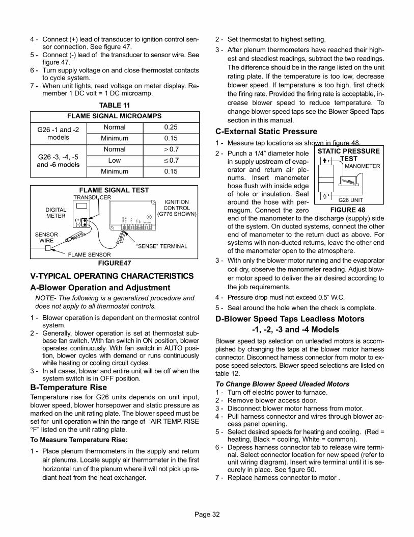
FIGURE 48
STATIC PRESSURETEST
MANOMETER
G26 UNIT
Page 32
4 − Connect (+) lead of transducer to ignition control sen-sor connection. See figure 47.
5 − Connect (−) lead of the transducer to sensor wire. Seefigure 47.
6 − Turn supply voltage on and close thermostat contactsto cycle system.
7 − When unit lights, read voltage on meter display. Re-member 1 DC volt = 1 DC microamp.
TABLE 11
FLAME SIGNAL MICROAMPS
G26 −1 and −2 Normal 0.25G26 1 and 2models Minimum 0.15
G26 3 4 5Normal �0.7
G26 −3, −4, −5and −6 models
Low �0.7and −6 models
Minimum 0.15
SENSORWIRE
FIGURE47
IGNITIONCONTROL
(G776 SHOWN)
�SENSE" TERMINAL
DIGITALMETER
FLAME SENSOR
FLAME SIGNAL TEST
(+)(−)
TRANSDUCER
V−TYPICAL OPERATING CHARACTERISTICS
A−Blower Operation and Adjustment
NOTE− The following is a generalized procedure and
does not apply to all thermostat controls.
1 − Blower operation is dependent on thermostat controlsystem.
2 − Generally, blower operation is set at thermostat sub-base fan switch. With fan switch in ON position, bloweroperates continuously. With fan switch in AUTO posi-tion, blower cycles with demand or runs continuouslywhile heating or cooling circuit cycles.
3 − In all cases, blower and entire unit will be off when thesystem switch is in OFF position.
B−Temperature RiseTemperature rise for G26 units depends on unit input,
blower speed, blower horsepower and static pressure as
marked on the unit rating plate. The blower speed must be
set for unit operation within the range of �AIR TEMP. RISE
°F" listed on the unit rating plate.
To Measure Temperature Rise:
1 − Place plenum thermometers in the supply and return
air plenums. Locate supply air thermometer in the first
horizontal run of the plenum where it will not pick up ra-
diant heat from the heat exchanger.
2 − Set thermostat to highest setting.
3 − After plenum thermometers have reached their high-
est and steadiest readings, subtract the two readings.
The difference should be in the range listed on the unit
rating plate. If the temperature is too low, decrease
blower speed. If temperature is too high, first check
the firing rate. Provided the firing rate is acceptable, in-
crease blower speed to reduce temperature. To
change blower speed taps see the Blower Speed Taps
section in this manual.
C−External Static Pressure
1 − Measure tap locations as shown in figure 48.
2 − Punch a 1/4" diameter hole
in supply upstream of evap-
orator and return air ple-
nums. Insert manometer
hose flush with inside edge
of hole or insulation. Seal
around the hose with per-
magum. Connect the zero
end of the manometer to the discharge (supply) side
of the system. On ducted systems, connect the other
end of manometer to the return duct as above. For
systems with non−ducted returns, leave the other end
of the manometer open to the atmosphere.
3 − With only the blower motor running and the evaporator
coil dry, observe the manometer reading. Adjust blow-
er motor speed to deliver the air desired according to
the job requirements.
4 − Pressure drop must not exceed 0.5" W.C.
5 − Seal around the hole when the check is complete.
D−Blower Speed Taps Leadless Motors
−1, −2, −3 and −4 Models
Blower speed tap selection on unleaded motors is accom-
plished by changing the taps at the blower motor harness
connector. Disconnect harness connector from motor to ex-
pose speed selectors. Blower speed selections are listed on
table 12.
To Change Blower Speed Uleaded Motors
1 − Turn off electric power to furnace.
2 − Remove blower access door.
3 − Disconnect blower motor harness from motor.
4 − Pull harness connector and wires through blower ac-cess panel opening.
5 − Select desired speeds for heating and cooling. (Red =heating, Black = cooling, White = common).
6 − Depress harness connector tab to release wire termi-nal. Select connector location for new speed (refer tounit wiring diagram). Insert wire terminal until it is se-curely in place. See figure 50.
7 − Replace harness connector to motor .

Page 33
FIGURE 49
To Remove Blower:
1− Turn off line voltage power. UnplugJ69 from P69 located on blowerdeck.
2− Disconnect thermostat wiring con-nections by removing low voltageterminal strip.
3− Disconnect J58/P58 located on blow-er deck.
4− Disconnect J43/P43 from blowermotor.
5− Loosen screws (2) and remove con-trol box from unit. Holes are slotted soscrews do not need to be removed.
6− Remove screws (2) and removeblower from unit. 4
526
3
1
5
FIGURE 50
BLOWER SPEED TAP SELECTIONHARNESS
CONNECTOR
MOTOR
DEPRESS TAB TO RELEASEWIRE TERMINAL. SELECTCONNECTOR LOCATION FORNEW SPEED (REFER TO UNITWIRING DIAGRAM). INSERTWIRE UNTIL IT IS SECURELYIN PLACE.
TABLE 12
TABLE 13
E−Blower Speed Taps Leaded Motors
−5 and −6 Models
Blower speed tap changes are made on the SureLightcontrol board. See figure 10. Unused taps must be se-cured on dummy terminals "PARK M1" and or "PARK M2"on the SureLight board. The heating tap is connected tothe "ACB HEAT " terminal and the cooling tap is connectedto the "ACB COOL" terminal. The continuous blower tap isconnected to the "ACB LOW" terminal.To change existing heat tap, turn off power then switch out
speed tap on "ACB HEAT" with tap connected to "PARK
M1" or "PARK M2". See table 13 for blower motor tap col-
ors for each speed.
VI−MAINTENANCE
Retainers for factory supplied return air filter are shown infigure 51.
FIGURE 51
BOTTOM RETURN FILTER
FURNACEBASE BOTTOM
REAR FILTER CLIP
RETURN AIROPENING
SIDE FILTER CLIPS (2)
FURNACEFRONT
FURNACEBACK
A−FiltersAt the beginning of each heating season, the systemshould be checked as follows:1 − Filters should be inspected monthly and must be
cleaned or replaced when dirty to ensure proper fur-nace operation.

Page 34
2 − Reusable foam filters used with the G26 can bewashed with water and mild detergent. When dry, theyshould be sprayed with filter handicoater prior to rein-stallation. Filter handicoater is RP Products coatingno. 418 and is available as Lennox part no. P-8-5069.
3 − If replacement is necessary, order Lennox part no.31J81 for 14" x 25" (356 x 635mm) filter for G26-50and -75 units and P-8-7831 for 20" x 25" (508 x635mm) filter for G26Q4/5−75,G26−100 and -125units.
B−Cleaning Heat Exchanger and Burners
If cleaning the heat exchanger becomes necessary, follow
the below procedures and refer to figure 1 when disas-
sembling unit. Use papers or protective covering in front of
furnace while removing heat exchanger assembly.
1 − Turn off electrical and gas power supplies to furnace.
2 − Remove upper and lower furnace access panels.
3 − Remove four (4) screws around air intake fitting and
lift intake pipe up and away.
4 − Loosen hose clamp securing top of flue transition to
bottom of flue collar. Remove screw securing flue col-
lar to top cap and lift exhaust pipe and flue collar up
and away.
5 − If electrical field make-up box is located inside the
unit, it must be removed.
6 − Remove gas supply line connected to gas valve.
7 − Mark all gas valve wires and disconnect them from
valve. Mark and remove wires from flame roll-out
switch.
8 − Remove top cap of unit.
9 − For −1 and −2 units, mark and disconnect spark and
sensor wire from ignition control. For −3 units, remove
sensor wire from SureLight control. Disconnect 2-pin
plug from the ignitor.
10− Mark and disconnect pressure switch tubing from
both sides of the pressure switch.
11− Loosen two (2) screws holding gas manifold support
at vestibule panel.
12− Remove four (4) burner box screws at the vestibule
panel and remove burner box and gas valve/manifold
assembly with bracket.
13− Drain condensate trap. Disconnect condensate line
from the outside of unit. Remove condensate line
from condensate trap by turning the adapter fitting
counterclockwise. The fitting has standard right hand
threads.
14− Disconnect the drain hose from the flue transition to
the elbow on the cold header (collector) box trap. On
−1 and −2 units remove two (2) screw from flue "Y" trap
at cabinet from door flange.
15− Disconnect the 2-pin plug from the combustion air
blower at the blower deck. Remove four (4) screws
from combustion air blower and remove flue transition
and blower assembly from cabinet. Take care not to
lose the combustion air orifice.
16− Disconnect 9-pin plug from the blower compartment
at the blower deck.
17− Remove 9-pin plug above the blower deck.
18− Remove the limit switch and the pressure switch from
the vestibule panel.
19− Remove two (2) screws from the front cabinet flange
at the blower deck. Remove front screws from cabinet
at blower deck on left and right sides. Cabinet sides
must be slightly spread to clear heat exchanger pas-
sage.
20− Remove screws along vestibule sides and bottom
which secure vestibule panel and heat exchanger as-
sembly to cabinet. Remove heat exchanger then re-
move cold end header box.
21− Back wash heat exchanger with soapy water solution
or steam. If steam is used it must be below 275�F
(135�C) .
22− Thoroughly rinse and drain the heat exchanger. Soap
solution can be corrosive so take care that entire as-
sembly is completely rinsed.
23− Re−install heat exchanger into cabinet making sure
that the clamshells of the heat exchanger assembly
are resting in the notches of the support located at the
rear of the cabinet. This can be viewed by removing
the indoor blower and examining through the blower
opening.
24− Re-secure the supporting screws along the vestibule
sides and bottom to the cabinet.
25− Re-install cabinet screws on sides and front flange at
blower deck.
26− Re-install the limit switch and pressure switch on the
vestibule panel.
27− Re-install 9-pin plug to blower deck and connect it to
the 9-pin plug from below the blower deck.
28− Re-install the combustion air blower. Be careful that
the plastic orifice on the blower inlet has not fallen out.
See figure 1. Reconnect the 2-pin plug to the wire har-
ness. Re-install the flue transition in the cabinet and
re-attach the drain tube. Route the drain tube below
the combustion air blower housing and to the elbow
on the cold header (collector) box trap. See figure 23.
29− Re-install condensate line with adapter to conden-
sate trap. Use fresh Teflon tape to ensure a leak−free
joint. Re-connect to condensate line outside of the
unit.

Page 35
Simplified Burner Removal:
1− Remove cover by looseningbottom screws (2) and re-moving cover front screws(5).
2− Remove pilot tube, sparkwire and sensor wire. Re-move gas valve and manifoldassembly.
3− Remove burner assembly.
FIGURE 52
BURNER ACCESS/REMOVAL
2
31
PATCH PLATEBARBED PRESSURESWITCH ORIFICE
BURNER MOUNTINGBRACKET
PATCH PLATE
UNIT VEST PANEL
30− Re-install the burner box. Tighten the screws holding
the support bracket. It is important that the glass fiber
gasket not be damaged so it will provide a continuous
seal between the burner box and the vestibule panel.
31− With the pressure switch oriented on the right, recon-
nect pressure switch tubing by connecting the tubing
from the burner box to the barb on the bottom and the
tubing from the combustion air blower to the barb on
the top. See figure 23.
32− Reconnect the sensor and ignitor wires.
33− Re-install top cap to unit.
34− Re-install electrical connections to gas valve. Orange
wire to M1 and yellow wire to C2. Reconnect wires to
flame roll-out switch.
NOTE − Unit is polarity-sensitive. 120V supply wiring
must be installed correctly.
35− Reconnect main gas line to gas valve.
36− Re-install field make-up box if removed.
37− Re-install exhaust pipe/flue collar and secure flue col-
lar to the unit top cap using existing screw. Insert the
bottom of the flue collar into the top of the flue transi-
tion and tighten hose clamp.
38− Re-install intake pipe fitting to burner box with screws.
39− Replace both upper and lower access panels.
40− Refer to instruction on verifying gas and electrical con-
nections when re-establishing supply.
41− Following lighting instructions from installation manu-
al, light and run unit for 5 minutes to ensure heat ex-
changer is clean, dry and operating safely.
Cleaning the Burner Assembly 1 − Turn off electrical and gas power supplies to furnace.
Remove upper and lower furnace access panels.
2 − Disconnect the gas supply line to gas valve. Depend-
ing on gas plumbing installation, the gas manifold
may move aside enough that breaking the union may
not be necessary.
3 − Remove five (5) screws from edges of burner box
cover. G26−50 units have only four (4) screws.
4 − Loosen two (2) screws on bottom of burner box front.
The cover is key holed at these screw point so screws
do not need to be removed. Pull off cover and set
aside.
6 − On −1 and −2 units disconnect pilot line at the gas
valve. On all units mark all gas valve wires and dis-
connect them from valve.
7 − ON −1 and −2 units mark and disconnect spark and
sensor wire from the burner box at the ignition control.
On −3 mark and disconnect sensor wires from the
burner box at the SureLight control. Disconnect 2-pin
plug from the ignitor at the burner box.
8 − Loosen two (2) screws at the gas manifold support
bracket.
9 − Pull on the left side of the gas manifold and follow with
tension to the right side. The manifold support bracket
will be free of the mounting screws on the vestibule
panel. Set the gas manifold/gas valve assembly
aside. Take care not to damage foam gaskets on each
end of the gas manifold.
10− Using a 1/4" nut driver, remove the burner mounting
screws from underneath the burners.

Page 36
11− While supporting pilot, ignitor and sensor wires (−1,−2
units) or ignitor and sensor lines (−3 units) at the grom-
met, grasp burners and simultaneously pull burners
and grommet out of the burner box.
12− Remove ignitor and sensor or pilot bracket assem-
blies from burners using a 1/4" nut driver to remove
two screws from each bracket.
13− Clean burner by running a vacuum with a soft brush at-
tachment over face of burners. Visually inspect inside of
burners and crossovers for any blockage caused by for-
eign matter. Remove any blockage.
14− Re-install ignitor and sensor bracket assemblies on
burners.
NOTE − Ignitor or pilot must be installed on the opposite
side of the burner from the metal button protrusions.
Screws which attached the ignitor bracket must be
installed from the same side as the ignitor and through
the bracket to engage in the smaller holes located in the
burner. The correct burner orientation is with metal but-
ton protrusions always pointing up.
15− Replace burner ignitor assembly back into burner box
so that grommet groove fits back into sheet metal
notch and makes a good seal. The burners sit on top
of the burner box flanges. Make certain that the
screws from underneath the box pass through the
larger holes in the flange and engage in the smaller
holes in the burner. Re-install the two screws.
16− Re-install the gas manifold/gas valve assembly by first
inserting the right hand side of the gas manifold into the
burner box. Swing left side of manifold into box while
engaging support bracket to vestibule panel screws.
Check that foam gaskets are providing a seal around
each end of the gas manifold. All gas orifices should be
engaged. If at this point the burners were mounted in
the wrong holes, this needs to be corrected. The saddle
brackets on the gas manifold should be flush with the
front surfaces on the burner box sides.
17− Inspect the dual layered metal pieces at the front lip of
the cover. These pieces must sandwich around the
metal. Re-install burner box cover.
18− Re-install the screws to secure the burner box cover.
Make sure screws are tight to ensure a leak tight burn-
er box. Tighten the two screws underneath the box.
Again, inspect the grommet to ensure a tight seal.
19− Tighten the two screws holding the manifold bracket
to the vestibule panel.
20− Re-install the electrical connections to the gas valve.
Orange wire to M1 and yellow wire to C2.
21− On −1 and −2 units re−install the spark wire (larger of
the two) to the barbed connector at the ignition con-
trol. Re−install the sensor wire to the spade connector
on the ignition control. On −3 units re-install the 2-pin
ignitor plug at the burner box. Re-install sensor line to
ignition control spade connector.
22− Reconnect gas line to gas valve. On −1 and −2 units
reconnect pilot line to gas valve.
23− Replace lower access panel.
24− Following lighting instructions and gas line connec-
tion test procedures from installation manual.
25− Replace upper access panel.
C−Supply Air Blower
1 − Check and clean blower housing and blower wheel.
2 − Motors are prelubricated for extended life; no furtherlubrication is required.
D−Electrical
1 − Check all wiring for loose connections.
2 − Check circuit breaker located in unit control box.
3 − Check for correct voltage at unit (unit operating).
4 − Check amp-draw on blower motor.
Motor Nameplate_________Actual_________
5 − Check to see that heat (if applicable) is operating.
E−Intake and Exhaust Lines
Check intake and exhaust lines and all connections for
tightness and make sure there is no blockage. Also check
condensate line for free flow during operation.
F−Insulation
Outdoor piping insulation should be inspected yearly for dete-
rioration. If necessary, replace with same materials.
G−Winterizing and Condensate Trap Care
1 − Turn off power to unit.
2 − Have a shallow pan ready to empty condensate water.
Avoid spilling water into the control box.
3 − Remove clamp from flue assembly and remove boot or
cap. Empty water from cap. Visually inspect bottom of
flue assembly. Replace boot and clamp.
4 − Remove boot from condensate trap and empty water.
Inspect trap then replace boot.

Page 37
VII−WIRING DIAGRAM, SEQUENCE OF OPERATION &TROUBLESHOOTINGA−Field Wiring, Thermostat Connections
FIGURE 53
G WY CR
SURELIGHT CONTROL
CONTROLBOX
THERMOSTAT
IGNITIONCONTROL
GASVALVE
LIMIT
BLACK
BROWN
TO COMPRESSORCONTACTOR
FIELD INSTALLED CLASS II 24V VOLTAGEFIELD INSTALLED LINE VOLTAGE
TYPICAL G26−3 through −6 MODELSFIELD WIRING DIAGRAM
L1 N
FU
SE
D D
ISC
ON
NE
CT
SW
ITC
H(F
UR
NIS
HE
D B
Y IN
STA
LL
ER
)
TRANSFORMER
DOORINTERLOCK
SWITCH
COMBUSTIONAIR BLOWER
COMBUSTIONAIR PROVE
SWITCH
FIELDMAKE−UP
BOX
GND
J69 WHITE
TO ACCESSORY IF USED. (ELECTRONIC AIR CLEANER)
IF NOT NEEDED, DO NOT INSTALLACCESSORY WIRE IN J69.
GW R Y
FLAMEROLLOUTSWITCH
FIGURE 54
COMPRESSOR�
COMMON
POWER
HEAT
INDOOR BLOWER
COMMON
HS UNITCOMMON
HS UNITCOMPRESSOR
Y
W
G26Furnace
Condensing UnitThermostat
G26 and CONDENSING UNITTHERMOSTAT DESIGNATIONS
(Refer to specific thermostat and outdoor unit.)
COOLINGY
G
W
C
R
G
R
C

Page 38
B−Wiring Diagram G26 (−3 & −4 Shown)
4
1
2
32
5
67
3

Page 39
HEATING SEQUENCE OF OPERATIONSURELIGHT CONTROL
NORMAL HEATING MODE ABNORMAL HEATING MODE
CONTROL SELF−CHECK OKAY?
BURNER OFF?(CONTINUOUS FLAME CHECK)
NORMAL OPERATION:LED #1 −− SLOW FLASHLED #2 −− SLOW FLASH
YES
YES
YES
GAS VALVE OFF. COMBUSTION AIR BLOWER OFF.INDOOR BLOWER DELAY OFF.
LED #1 ONLED #2 ON
(RESET CONTROL BY TURNING MAIN POWER OFF.)
POLARITY REVERSED.LED #1 −− FAST FLASHLED #2 −− SLOW FLASH
POWER ON
COMBUSTION AIR BLOWER ON FOR 1 SECOND.
TURN INDUCER ON FOR 1 SECOND.IS POLARITY REVERSED?
ROLLOUT SWITCH CLOSED?
THERMOSTAT CALLS FOR HEAT:LED #1 −− FAST FLASHLED #2 −− FAST FLASH
IS COMBUSTION AIRPRESSURE SWITCH OPEN?
GAS VALVE OFF. COMBUSTION AIR BLOWER OFF.INDOOR BLOWER OFF WITH DELAY.LED #1 −− ON. LED #2 −− SLOW FLASH.
SEQUENCE HOLDS UNTIL ROLLOUT SWITCH CLOSES.
GAS VALVE OFF. COMBUSTION AIR BLOWER ON.INDOOR BLOWER ON HEATING SPEED.
LED #1 −− SLOW FLASHLED #2 −− OFF
GAS VALVE OFF.COMBUSTION AIR BLOWER OFF.
INDOOR BLOWER OFF WITH DELAY.LED #1 OFF
LED #2 SLOW FLASH(Sequence holds until pressure switchcloses or thermostat resets control.)
NOYES
NO
IS THEREPROPER GROUND?
IS VOLTAGEABOVE 75 VOLTS?
LOW VOLTAGE SIGNAL AT LED HOLDSUNTIL VOLTAGE RISES ABOVE 75 VOLTS.
NOYES
NO
SIGNAL IMPROPERGROUND AT LED.SIGNAL HOLDSUNTIL UNIT IS
PROPERLYGROUNDED.
NO
NO
IS COMBUSTION AIR BLOWER ENERGIZED? (HTG ACC TERMINAL IS ENERGIZED WITH C.A.B.)
HAS COMBUSTION AIR PRESSURESWITCH CLOSED IN 2.5 MINUTES?
YES
YESPRESSURE SWITCH IS IN WATCHGUARD MODE.
GAS VALVE OFF. COMBUSTION AIR BLOWER OFF.INDOOR BLOWER OFF WITH DELAY.
LED #1 −− OFF. LED #2 −− SLOW FLASH.IS 5-MINUTE RESET PERIOD COMPLETE?
NO
15-SECOND COMBUSTION AIR BLOWER PREPURGEINITIATED BY CLOSED PRESSURE SWITCH.
YES
YES
CONTINUED NEXT PAGE
YES
NO
GAS VALVE OFF. COMBUSTION AIR BLOWER ON.INDOOR BLOWER ON.
LED #1 ALTERNATING FAST FLASHLED#2 ALTERNATING FAST FLASHCHECK FOR BROKEN IGNITOR OR
OPEN IGNITOR CIRCUIT

Page 40
HEATING SEQUENCE CONTINUED
NORMAL HEATING MODE ABNORMAL HEATING MODE
FLAME RECTIFICATION CURRENT CHECKCAN FLAME BE PROVEN WITHIN 4
SECONDS AFTER GAS VALVE OPENS?(�0.15 microamps)
NOFLAME PRESENT?
INDOOR BLOWER ON DELAY BEGINS. AFTER 45SECOND DELAY, ACB HEAT SPEED AND ACC
TERMINAL IS ENERGIZED.
PRIMARY AND SECONDARY LIMITSWITCHES CLOSED?
COMBUSTION AIR PRESSURESWITCH CLOSED?
LOW FLAME SIGNAL(Does not affect operation of control)
LED #1 −− SLOW FLASHLED #2 −− FAST FLASH
GAS VALVE DE−ENERGIZED.COMBUSTION AIR BLOWER DE−ENERGIZED.
INDOOR BLOWER ON UNTIL SWITCH CLOSES.LED #1 −− SLOW FLASH. LED #2 −− ON.
IS LIMIT SWITCH CLOSED?
GAS VALVE DE−ENERGIZED.COMBUSTION AIR BLOWER ON.
INDOOR BLOWER OFF WITH DELAYLED #1 −− OFF. LED #2 −− SLOW FLASH.
HAS CAB SWITCH CLOSED IN 2.5 MINUTES?
15-SECOND COMBUSTION AIR BLOWER PREPURGEINITIATED BY CLOSED PRESSURE SWITCH.
YES
IGNITOR WARM-UP −− 20 SECONDS.
YES
4-SECOND TRIAL FOR IGNITION. GAS VALVEOPENS. IGNITOR ENERGIZED FOR 1 SECOND
AFTER VALVE OPENS. BOARD 97L48 ONLY: IGNITORENERGIZED FOR FULL 4−SECOND IGNITION TRIAL.
YES
FLAME STABILIZATION PERIOD.
GAS VALVE OFF. COMBUSTION AIR BLOWER ON.INDOOR BLOWER OFF.
HAS CONTROL FAILED TO SENSE FLAME FORFIVE CONSECUTIVE TRIES DURING A SINGLE
HEAT DEMAND?
NO
WATCHGUARD MODE. GAS VALVE OFF.COMBUSTION AIR BLOWER OFF.
INDOOR BLOWER OFF WITH DELAYLEDs SIGNAL WATCHGUARD FAILURE CODE.
IS 60-MINUTE RESET PERIOD COMPLETE?
YES
YES
NO
4 SECONDS
YES
HAS CONTROL RESET IGNITIONSEQUENCE FOUR TIMES?
YES
NO
FLAME SIGNAL ABOVE 0.7 MICROAMPS?
NO
YES
YES
HAS PRIMARY/SECONDARY LIMIT RESET?(See table 2 DIAGNOSTIC CODES for limit reset operation)
NO
YES
NO
YES
ROLLOUT SWITCH CLOSED?
GAS VALVE OFF. COMBUSTION AIR BLOWER OFF.INDOOR BLOWER OFF WITH DELAY.LED #1 −− ON. LED #2 −− SLOW FLASH.
SEQUENCE HOLDS UNTIL ROLLOUT SWITCH CLOSES.
NO
YES
YESNO
THERMOSTAT DEMAND SATISFIED.
LED #1 & #2 SIMULTANEOUS SLOW FLASHES.
COMB. AIR BLOWER CONTINUES 5-SECOND POSTPURGE AFTER T’STAT DEMAND IS SATISFIED. IN-
DOOR AIR BLOWER COMPLETES SELECTED �OFF"DELAY BEFORE SHUTTING OFF. ACB HEAT, HTG
ACC AND ACC TERMINALS DE−ENERGIZED.
YES
YES
YES
NO
5-MINUTE PRESSURE SWITCHWATCHGUARD MODE.
YES

Page 41
COOLING SEQUENCE OF OPERATIONSURELIGHT CONTROL
NORMAL COOLING MODE ABNORMAL COOLING MODE
IGNITION CONTROL MAIN POWER ON.
CONTROL SELF DIAGNOSTIC CHECK.IS CONTROL OPERATING NORMALLY?
YES
SIGNAL POLARITY REVERSED AT LED.
POWER ON
GAS VALVE OFF. COMBUSTION AIR BLOWER OFF.INDOOR BLOWER OFF WITH NORMAL DELAY.
SIGNAL CIRCUIT BOARD FAILURE AT LED.INTERRUPT MAIN POWER TO RESET CONTROL.
YES
TURN INDUCER ON FOR 1 SECOND.
IS POLARITY REVERSED?
ROLLOUT SWITCH MONITORED CONTINUOUSLY.IS ROLLOUT SWITCH CLOSED?
CHECK FOR MAIN BURNER FLAME SENSE.IS MAIN BURNER FLAME OFF?
LED: SLOW FLASH RATE REMAINS UNCHANGEDTHROUGHOUT COOLING CYCLE.
THERMOSTAT CALLS FOR COOLING.
COMPRESSOR CONTACTOR AND SYSTEM FANENERGIZED WITH 0-SECOND DELAY. ACB COOL
SPEED AND ACC. TERMINAL IS ENERGIZED.
COMPRESSOR OFF.
THERMOSTAT OPENS.
SYSTEM FAN AND ACC. TERM. OFFWITH 0-SECOND DELAY.
NO
YES
NO
GAS VALVE OFF. COMBUSTION AIR BLOWER OFF.INDOOR BLOWER OFF WITH NORMAL DELAY.
SIGNAL CIRCUIT BOARD FAILURE AT LED.SEQUENCE HOLDS UNTIL ROLLOUT SWITCH CLOSES.
NO
GAS VALVE OFF. COMBUSTION AIR BLOWER OFF.INDOOR BLOWER OFF WITH NORMAL DELAY.
SIGNAL CIRCUIT BOARD FAILURE AT LED.SEQUENCE HOLDS UNTIL FLAME IS NOT SENSED.
NO
IS THEREPROPER GROUND?
IS VOLTAGEABOVE 75 VOLTS?
LOW VOLTAGE SIGNAL AT LET HOLDSUNTIL VOLTAGE RISES ABOVE 75 VOLTS.
NOYES
NO
SIGNAL IMPROPERGROUND AT LED.SIGNAL HOLDSUNTIL UNIT IS
PROPERLYGROUNDED.

Page 42
CONTINUOUS LOW SPEED FAN SEQUENCE OF OPERATIONSURELIGHT CONTROL
LED: SLOW FLASH RATE REMAINSUNCHANGED THROUGHOUT SEQUENCE.
MANUAL FAN SELECTION MADE AT THERMOSTAT.CONTROL (G) ENERGIZES SYSTEM FAN AT ACBLOW SPEED. ACC. TERMINAL IS ENERGIZED.
THERMOSTAT CALLS FOR HEAT (W).
THERMOSTAT CALLS FOR COOLING.
BOARD NO. 63K8901SYSTEM FAN DE−ENERGIZED. SYSTEM FANENERGIZES ON ACB HEAT SPEED AFTER
NORMAL DELAY.
THERMOSTAT OPENS. COMBUSTION AIRAND HTG ACC TERMINAL DE−ENERGIZE.
SYSTEM FAN SWITCHED TO ACB COOLSPEED. ACC. TERM. REMAINS ON.
THERMOSTAT OPENS.
BOARD 63K89: SYSTEM FAN OFF. ACC. TERM.OFF. (AFTER OFF DELAY COMPLETED).
MANUAL FAN SELECTION MADE AT THERMOSTAT.CONTROL (G) ENERGIZES SYSTEM FAN AT ACB
LOW SPEED. ACC. TERM. ENERGIZED.
NO YES
YESNO
HTG ACC. TERM. ENERGIZES WITH COMB. AIR BLOWER.
BOARD NO. 24L85, 56L83, 97L48SYSTEM FAN SWITCHES TO ACB HEAT SPEEDAFTER NORMAL DELAY (fan remains energized)
BOARDS 24L85, 56L83 AND 97L48:SYSTEM FAN SWITCHES TO
LOW SPEED AFTER NORMAL DELAY.(fan remains energized)
C−Heating Sequence of Operation
1 − When there is a call for heat, W1 of the thermostat en-
ergizes W of the furnace control with 24VAC.
2 − S10 primary limit switch and S47 rollout switch are
closed. Call for heat can continue.
3 − Surelight control energizes combustion air blower B6.
Combustion air blower runs until S18 combustion air
prove switch closes (switch must close within 2−1/2
minutes or control goes into 5 minute Watchguard
Pressure Switch delay). Once S18 closes, a 15−sec-
ond pre−purge follows.
4 − Surelight control energizes ignitor. A 20−second
warm−up period begins.
5 − Gas valve opens for a 4−second trial for ignition.
6 − Flame is sensed, gas valve remains open for the heat
call.
7 − After 45−second delay, Surelight control energizes in-
door blower B3.
8 − When heat demand is satisfied, W1 of the indoor ther-
mostat de−energizes W of the Surelight control which
de−energizes the gas valve. Combustion air blower
B6 continues a 5−second post−purge period, and in-
door blower B3 completes a selected OFF time delay.

Page 43
D− SureLight Control Trouble Shooting GuideUPON INITIAL POWER UP, REMOVE ALL THERMOSTAT DEMANDS TO THE UNIT
PROBLEM: 1 UNIT FAILS TO OPERATE IN THE COOLING, HEATING, OR CONTINUOUS FAN MODE
Condition Possible Cause Corrective Action / Comments
1.1
− Both diagnostic lights fail to light up.
1.1.1
Main voltage 120V not supplied tounit.
ACTION 1 − Check 120V main voltage.Determine cause of main power failure.
LED#1−OffLED#2−Off
1.1.2
Miswiring of furnace or improperconnections.
ACTION 1 − Check for correct wiring of 120V topower make up box and transformer.ACTION 2 − Check 24V wiring to control board.
1.1.3
Circuit breaker tripped or fails toclose.
ACTION 1 − Replace circuit breaker if it is resetbut does not have continuity.ACTION 2 − If circuit breaker still trips, check forshort.
1.1.4
Door interlock switch failure.
ACTION 1 − Check that door switch is activatedwhen door is closed.ACTION 2 − Check wire connections to switch, re-place loose connectors.ACTION 3 − Check continuity of switch in closedposition. Replace if malfunctioning
1.1.5
Transformer Failure.
ACTION 1 − Check that transformer output is24V. Replace if malfunctioning
1.1.6
Failed control board.
ACTION 1 − If all the above items have beenchecked, replace board.
1.2
− Diagnostic lights flash the roll−out
code.
1.2.1
Roll−out switch open.
ACTION 1 − Manually reset the roll−out switchby pushing the top button.ACTION 2 − Determine the cause of the roll−outswitch activation before leaving furnace.code.
LED#1 O
1.2.2
Roll−out switch failure.
ACTION 1 − Check continuity across roll−outswitch. Replace roll−out switch if switch is resetbut does not have continuity.
LED#1−On,
LED#2−Slow Flash1.2.3
Mis iring or improper connections at ACTION 1 − Check wiring connections to switchLED#2 Slow FlashMiswiring or improper connections atroll−out switch.
ACTION 1 − Check wiring connections to switch.
1.2.4
Nine pin connector failure
ACTION 1 − Check 9−pin connector for properconnection to control board.ACTION 2 − Check continuity of the multi plugpin.
1.3
− On initial power−up the comb. airblower does not energize.blower does not energize. − Diagnostic lights flash the reversepolarity code.
1.3.1
120V main power polarity reversed.
ACTION 1 − Check the 120V has line and neutralcorrectly input into control.ACTION 2 − Reverse the line and neutral at the120V field connection.
LED#1−Fast Flash,LED#2−Slow Flash.
120V field connection.
1.4
− On initial power up the combustionair blower does not energize. − Diagnostic lights flash normal poweron operation.
1.4.1
Open combustion air blower motorcircuit.
ACTION 1 − Check for 120V to combustion airblower. If no power, check wire and connec-tions.
on operation.
LED#1−Slow FlashLED#2−Slow Flash
1.4.2
Failed combustion air blower motor.
ACTION 1 − If power is present at blower, replaceblower.

Page 44
PROBLEM 1: UNIT FAILS TO OPERATE IN THE COOLING, HEATING, OR CONTINUOUS FAN MODE
Condition Possible Cause Corrective Action / Comments
1.5
− On initial power−up the combustionair blower remains energized.
Di ti li ht fl h th i
1.5.1
Improper ground to the unit.
ACTION 1 − Check that the unit is properlyground.ACTION 2 − Install a proper main ground to theunitg
− Diagnostic lights flash the impropermain ground.
1.5.2
6−Pin connector is improperly at-tached to the circuit board.
ACTION 1 − Check 6−pin connector for properinstallation. Correctly insert connector into con-trol.
LED#1−Alternating Fast FlashLED#2−Alternating Fast Flash
1.5.3
Line voltage is below 75V.
ACTION 1 − Check that the line voltage is above75V. Determine cause of voltage drop and sup-ply correct voltage to the control.
PROBLEM 2: UNIT FAILS TO OPERATE IN THE COOLING OR HEATING MODE, BUT COMBUS-TION AIR BLOWER OPERATES CONTINUOUS. UNITS WITH CONTROL BOARDS DATE CODED
AFTER NOV.1 1997, WILL OPERATE IN COOLING BUT NOT IN THE HEATING MODE, WITH COM-BUSTION AIR BLOWER CYCLING 5 SECONDS ON 55 SECONDS OFF.
Condition Possible Cause Corrective Action / Comments
2.1
− On initial power−up the combustionair blower remains energized. − Diagnostic lights flash the impropermain ground. − Units with control boards datecoded after Nov 1 1997; combustion
2.1.1
Open ignitor circuit.
ACTION 1 − Check for correct wiring and looseconnections in the ignitor circuit. Check mult−plug connections for correct installation.
coded after Nov.1 1997; combustionair blower will cycle 5 seconds on 55seconds off.
LED#1−Alternating Fast FlashLED#2−Alternating Fast Flash
2.1.2
Broken or failed ignitor.
ACTION 1 − Unplug ignitor and read resistanceacross ignitor. If resistance does not read be-tween 10.9 and 19.7 ohms, replace the ignitor.
PROBLEM 3: UNIT FAILS TO FIRE IN THE HEATING MODE, COMBUSTION AIR BLOWER DOESNOT ENERGIZE
Condition Possible Cause Corrective Action / Comments
3.1
− Unit operates with a cooling or con-tinuous fan demand. − Combustion air blower will not startwith a Heating demand. − Diagnostic lights flash the limit failure
d
3.1.1
Primary or secondary (if equipped)limit open.
ACTION 1 − Check continuity across switch(es).Switches reset automatically upon cool down.ACTION 2 − Check for restrictions on blower inletair (including filter) and outlet air. Determinecause for limit activation before placing unit backin operation.
g gmode.
LED#1−Slow Flash,LED#2−On
3.1.2
Miswiring of furnace or improper con-nections at limit switch(es).
ACTION 1 − Check for correct wiring and looseconnections. Correct wiring and/or replace anyloose connections.
3.2
− Unit operates with a cooling and con-tinuous fan demand. − Combustion air blower will not startwith a Heating demand. − Diagnostic lights flash the pressure
3.2.1
Miswiring of furnace or improper con-nections to combustion air blower.
ACTION 1 − Check for correct wiring and looseconnections. Correct wiring and/or replace anyloose connections.
− Diagnostic lights flash the pressureswitch failure code.
LED#1−Off,LED#2−Slow Flash
3.2.2
Pressure switch stuck closed.
ACTION 1 − Check that the pressure switch isopen without the combustion air blower operat-ing. Replace if malfunctioning

Page 45
PROBLEM 3: UNIT FAILS TO FIRE IN THE HEATING MODE, COMBUSTION AIR BLOWER DOESNOT ENERGIZE (CONT.).
Condition Possible Cause Corrective Action/Comments
3.3
− Unit operates with a cooling and con-tinuous fan demand. − Combustion air blower will not startwith a Heating demand. − Diagnostic lights flash the pressureswitch failure code 2 5 minutes after
3.3.1
Miswiring of furnace or improper con-nections to combustion air blower.
ACTION 1 − Check for correct wiring and looseconnections. Correct wiring and/or replace anyloose connections.
switch failure code 2.5 minutes afterheating demand.
LED#1−Off, LED#2−Slow Flash
3.3.2
Combustion air blower failure.
ACTION 1 − If there is 120V to combustion airblower and it does not operate, replace combus-tion air blower.
PROBLEM 4: UNIT FAILS TO FIRE IN THE HEATING MODE, COMBUSTION AIR BLOWER ENERGIZES, IGNITOR IS NOT ENERGIZED.
Condition Possible Cause Corrective Action/Comments
4.1
− Unit operates with a cooling andcontinuous fan demand. − Combustion air blower energizeswith a heating demand
4.1.1
Pressure switch does not close dueto incorrect routing of the pressure
switch lines.
ACTION 1 − Check that the pressure switch linesare correctly routed. Correctly route pressureswitch lines.
with a heating demand. − Diagnostic lights flash the pressureswitch failure code 2.5 minutes afterheating demand.
4.1.2
Pressure switch does not close dueto obstructions in the pressure lines.
ACTION 1 − Remove any obstructions from thethe pressure lines and/or taps.
g
LED#1−Off
4.1.3
Pressure switch lines damaged
ACTION 1 − Check pressure switch lines forleaks. Replace any broken lines.
LED#1 OffLED#2−Slow Flash 4.1.4
Condensate in pressure switch line.
ACTION 1 − Check pressure switch lines for con-densate. Remove condensate from lines. Checkthat the condensate lines are located correctly.
4.1.5
Pressure switch does not close dueto a low differential pressure across
the pressure switch.
ACTION 1 − Check the differential pressure
across the pressure switch. This pressure
should exceed the set point listed on the
switch.
ACTION 2 − Check for restricted inlet and ex-
haust vent. Remove all blockage.
ACTION 3 − Check for proper vent sizing and
run length. See installation instructions.
4.1.6
Wrong pressure switch installed inthe unit, or pressure switch is out of
calibration.
ACTION 1 − Check that the proper pressureswitch is installed in the unit. Replace pressureswitch if necessary.
4.1.7
Miswiring of furnace or improper con-nections at pressure switch.
ACTION 1 − Check for correct wiring and looseconnections. Correct wiring and/or replace anyloose connections.
4.1.8
Pressure switch failure.
ACTION 1 − If all the above modes of failure havebeen checked, the pressure switch may havefailed. Replace pressure switch and determine ifunit will operate.

Page 46
PROBLEM 5: UNIT FAILS TO FIRE IN THE HEATING MODE, COMBUSTION AIR BLOWER ENERGIZES, IGNITOR IS ENERGIZED. (CONT.)
Condition Possible Cause Corrective Action/Comments
5.1
− Unit operates with a cooling and
continuous fan demand.
Combustion air blower energizes
5.1.1
Check that gas is being supplied tothe unit.
ACTION 1 − Check line pressure at the gasvalve. Pressure should not exceed 13" WC forboth natural and propane. Line pressure shouldread a minimum 4.5" WC for natural and 8.0"WCfor propane.
− Combustion air blower energizes
with Heating demand.
− Ignitor is energized but unit fails to
light.
5.1.2
Miswiring of gas valve or loose con-nections at multi−pin control amp
plugs or valve.
ACTION 1 − Check for correct wiring and looseconnections. Correct wiring and/or replace anyloose connections.
LED#1−Alternating Slow Flash
LED#2−Alternating Slow Flash
5.1.3
Malfunctioning gas valve or ignitioncontrol.
ACTION 1 − Check that 24V is supplied to thegas valve approximately 35 seconds after heatdemand is initiated.ACTION 2 − Replace the valve if 24V is suppliedbut valve does not open (check for excessivegas line pressure before replacing gas valve).ACTION 3 − Replace the control board if 24V isnot supplied to valve.
PROBLEM 6: BURNERS LIGHT WITH A HEATING DEMAND BUT UNIT SHUTS DOWN PREMATURELY
Condition Possible Cause Corrective Action/Comments
6.1
− Burners fire with a heating de-mand.
6.1.1
Wrong concentric vent kit used forterminating the unit.
ACTION 1 − Check vent termination kit installed.1−1/2" dia. concentric vent (kit60G77) for 50 and75 inputs and 2" dia. concentric vent (kit 33K97)for 100 &125 inputs.
− Burners light but unit shuts off priorto satisfying T−stat demand. − Diagnostic lights flash the pressureswitch code.
6.1.2
Condensate drain line is not drainingproperly.
ACTION 1 − Check condensate line for propervent slope, and any blockage. Condensateshould flow freely during operation of furnace.Repair or replace any improperly installed con-densate lines.
LED#1−OffLED#2−Slow Flash
6.1.3
Low pressure differential at the pres-sure switch.
ACTION 1 − Check for restricted vent inlet or ex-haust. Remove all blockage.ACTION 2: Check for proper vent sizing. Seeinstallation instructions.
6.2
− Combustion air blower energizeswith a heating demand.
B li ht b t f il t t lit
6.2.1
Sensor or sense wire is improperlyinstalled.
ACTION 1 − Check that sensor is properly lo-cated (page 10) and that the sense wire isproperly attached to both the sensor and thecontrol.
− Burners light but fail to stay lit. − After 5 tries the control diagnosticsflash the watchguard burners failed toignite code.
6.2.2
Sensor or sense wire is broken.
ACTION 1 − Check for a broken sensor.ACTION 2 − Test continuity across the sensewire. If wire or sensor are damaged replacethe component.ignite code.
LED#1−Alternating Slow FlashLED#2−Alternating Slow Flash
6.2.3
Sensor or sensor wire is grounded tothe unit.
ACTION 1 − Check for resistance between thesensor rod and the unit ground.ACTION 2 − Check for resistance between thesensor wire and the unit ground.ACTION 3 − Correct any shorts found in circuit.
6.2.4
Control does not sense flame.
ACTION 1 − Check the microamp signal fromthe burner flame. If the microamp signal is be-low 0.70 microamps, check the sense rod forproper location or contamination.ACTION 2 − Replace, clean, or relocate flamesense rod. If rod is to be cleaned, use steelwool or replace sensor. DO NOT CLEAN RODWITH SAND PAPER. SAND PAPER WILLCONTRIBUTE TO THE CONTAMINATIONPROBLEM. NOTE: Do not attempt to bendsense rod.

Page 47
PROBLEM 6: BURNERS LIGHT WITH HEATING DEMAND BUT UNIT SHUTS DOWN PREMATURELY (CONT.)
Condition Possible Cause Corrective Action/Comments
6.3
− Combustion air blower energizeswith a heating demand. − Burners light. − Roll−out switch trips during theheating demand. − Diagnostic lights flash roll−out fail-ure.
6.3.1
Unit is firing above 100% of thenameplate input.
ACTION 1 − Check that the manifold pressurematches value listed on nameplate. See installa-tion instructions for proper procedure.ACTION 2 − Verify that the installed orifice sizematch the size listed on the nameplate or instal-lation instructions.ACTION 3 − Check gas valve sensing hose to in-sure no leaks are present.ACTION 4 − Check the input rate to verify ratematches value listed on nameplate.ure.
LED#1−OnLED#2−Slow Flash
6.3.2
Gas orifices leak at the manifold con-nection.
ACTION 1 − Tighten orifice until leak is sealed.NOTE: Be careful not to strip orifice threads. AC-TION 2 − Check for gas leakage at the threadedorifice connection. Use approved method forleak detection (see unit instructions).
6.3.3
Air leakage at the connections be-tween the primary heat exchanger,
secondary heat exchanger, and com-bustion air blower.
ACTION 1 − Check for air leakage at all joints inthe heat exchanger assembly. Condition willcause high CO2 with high CO.ACTION 2 − Seal leakage if possible (high tem-perature silicon is recommended), replace heatexchanger if necessary, tag and return heat ex-changer to proper Lennox personnel.
6.3.4
Insufficient flow through the heat ex-changer caused by a sooted or re-
stricted heat exchanger.
ACTION 1 − Check for sooting deposits or otherrestrictions in the heat exchanger assembly.Clean assembly as outlined in instruction manu-al.ACTION 2 − For G26 gas furnaces, check forproper combustion and flow. CO2 should mea-sure between 6.0% and 8.0% for NG and be-tween 7.5% and 9.5% for LP. CO should mea-sure below .04% (400PPM) in an air−free sampleof flue gases for either NG or LP.
6.3.5
Burners are not properly located inthe burner box.
ACTION 1 − Check that the burners are firing intothe center of the heat exchanger openings. Cor-rect the location of the burners if necessary.
6.4
− Combustion air blower energizeswith a heating demand. − Burners light roughly and the unitfails to stay lit. − Diagnostic lights flash watchguardflame failure.
6.4.1
Recirculation of flue gases. This con-dition causes rough ignitions and op-eration. Problem is characterized by
nuisance flame failures.
ACTION 1 − Check for proper flow of exhaustgases away from intake vent. Remove any ob-stacles in front of the intake and exhaust ventwhich would cause recirculation.ACTION 2 − Check for correct intake and ex-haust vent installation. See instructions
flame failure.
LED#1−Alternating Slow FlashLED#2−Alternating Slow Flash
6.4.2
Improper burner cross−overs
ACTION 1 − Remove burner and inspect thecross−overs for burrs, or any restriction or ifcrossover is warped. Remove restriction or re-place burners.

Page 48
PROBLEM 6: BURNERS LIGHT WITH HEATING DEMAND BUT UNIT SHUTS DOWN PREMATURELY (CONT.)
6.5
− Combustion air blower energizeswith a heating demand. − Burners light. − Diagnostic lights flash watch guardflame failure. − NOTE" Unit might go into 60 min-ute Watchguard mode depending onintermittent nature of sensor signal.
LED#1−Alternating Slow FlashLED#2−Alternating Slow Flash
6.5.1
Loose sensor wire connectioncauses intermittent loss of flame sig-
nal.
ACTION 1 − Check that the sensor is properly lo-cated.ACTION 2 − Check that the sense wire is proper-ly attached to both the sensor and the control.Pay extra attention to the pin connectors.
PROBLEM 7: CONTROL SIGNALS LOW FLAME SENSE DURING HEATING MODE
Condition Possible Cause Corrective Action/Comments
7.0
− Unit operates correctly but thediagnostic lights flash low flamesense code
7.1.1
Sense rod is improperly located onthe burner.
ACTION 1 − Check the sense rod for proper loca-tion on the burner. Properly locate the sense rodor replace if rod cannot be located correctly.
sense code.
LED#1−Slow FlashLED#2−Fast Flash
7.1.2
Sense rod is contaminated.
ACTION 1 − Check sense rod for contaminationor coated surface. Clean the sense rod with steelwool or replace sensor. DO NOT USE SAND PA-PER TO CLEAN ROD. SAND PAPER WILLCONTRIBUTE TO THE CONTAMINATIONPROBLEM.
PROBLEM 8: INDOOR BLOWER FAILS TO OPERATE IN COOLING, HEATING, OR CONTINUOUSFAN MODE
Condition Possible Cause Corrective Action/Comments
8.0
− Indoor blower fails to operate incontinuous fan, cooling, or heatingmode.
8.1.1
Miswiring of furnace or improper con-nections at control or indoor blower
motor.
ACTION 1− Correct wiring and/or replace anyloose connections. Check for correct wiring andloose connections.
8.1.2
120V is not being supplied to the in-door air blower or blower motor fail-
ure.
ACTION 1 − Check for 120V at the various callsfor indoor blower by energizing "Y", "G", and "W"individually on the low voltage terminal strip.Note that when "W’ is energized, the blower isdelayed 45 seconds. If there is 120V to each mo-tor tap but the blower does not operate, replacethe motor.
8.1.3
Defective control board
ACTION 1 − If there is not 120V when "Y", "G", or"W" is energized, replace the control.
PROBLEM 9: RF STATIC DURING TIME FOR IGNITION
Condition Possible Cause Corrective Action/Comments
−AM radio interference Ignitor operation ACTION 1− Call Technical Support, Dallas

Page 49
2
3
5
6
4
1
7 8
E− G26 −1 and −2 Models 1- When disconnect is closed, 120V is routed through
door interlock switch (S51) to feed the line voltageside of the blower control (A3) and transformer T1 pri-mary. Door interlock switch must be closed for A3 andT1 to receive voltage.
2- T1 supplies 24VAC to terminal �24VAC" on A3. In turn,terminal �R" of A3 supplies 24VAC to terminal �RC" ofthe indoor thermostat (not shown).
3- When there is a call for heat, W1 of the thermostat en-ergizes W of the furnace control with 24VAC.
4- CAB of the blower control energizes the combustionair blower (B6). When the combustion air blower nearsfull speed, combustion air prove switch (S18) closes.
5- When S18 closes, assuming primary limit (S10) isclosed, the ignition control opens the pilot valve andbegins spark.
6- When flame is sensed, spark stops and main valveopens to light main burners.
7- After 45 seconds, blower control (A3) energizes the in-door blower.
8- When heat demand is satisfied, W1 of the thermostatde-energizes W of the furnace control and the furnacecontrol immediately de-energizes the gas valve. Thecombustion air blower immediately stops. Also, the in-door blower runs for a designated period (90−330 sec-onds) as set by jumper on blower control.

Page 50
F−BCC2 Blower Control −1 and −2 Models
CHECK:1−UNIT POWER
2−INTERLOCK SWITCH3−TRANSFORMER4−LIMIT SWITCH
START
IS24VAC ACROSS
R & T?
YES
JUMPER ACROSSSCREWS R & G
YES
DOES UNITOPERATE?
NO
NO
ISBLOWER
RUNNING ON HIGHSPEED?
NOIS
120VAC ACROSSN1 & A?
REPLACEBCC2
NOYES
YES
CHECK BLOWERWIRING AND
BLOWER
IS120VAC ACROSS
N1 & ACC?
NOREPLACEBCC2
YES
JUMPER ACROSS R &W
(REMOVE R & G JUMPER)
ISCOMB. AIR BLOWER
ON?
NO
REPLACEBCC2
NO IS120VAC ACROSS
N1 & CAB?
CHECKCOMBUSTION AIR BLOWER
YES
YES ARE BURNERSLIT?
NO
CHECK:1−COMBUSTION AIR BLOWER
2−IGNITION CONTROL3−GAS VALVE
4−IGNITOR5−LIMIT SWITCHES6−PROVE SWITCHYES
IS BLOWER RUNNING ON LOW
SPEED, 45 SEC.AFTER FURNACE
LIGHTS?
NOIS
120VAC ACROSSN1 & H?
YES
IS24VAC ACROSS
T & V?
REPLACEBCC2
NO
NO
CHECKWIRING
YESIS120VAC ACROSS
N1 & ACC?
YES
REMOVER & W
JUMPER
AFTERTHE SELECTEDTIME, DOES THEBLOWER TURN
OFF?
YES NO
YES
REPLACEBCC2
END OF TEST
BCC2TROUBLESHOOTING
FLOWCHART
NO
REPLACEBCC2
CHECK BLOWERWIRING AND
BLOWER
FIGURE 55
CHECK CIRCUITBREAKER. RESET IF
NECESSARY.

Page 51
G−G77 Ignition Control −1 and −2 Models
START
YES
NO
G776 IGNITION CONTROL TROUBLESHOOTING
Spark is present but pilot will not light
1993 Johnson Controls, Inc. Reprinted with permission.
Are pilot valveconnections correct
and secure?
Securely connect atterminal 1 and
ground.
Is 24VACbetween terminals 1
and ground?
ReplaceControl.
Is inletgas pressure permanufacturer’sspecifications?
Correct gaspressure.
WARNING
Explosion Hazard. Do not use match totest for gas pressure.
Is gas at pilotburner?
Make sure pilot lineis not kinked or
obstructed. Checkfor clean orifice.
If OK, replacepilot valve.
Is sparkgap 0.1 inch andlocated in pilot
stream?
Correct or replacepilot burner.
Shield from drafts.Check for clean orifice.
END
YES
YES
YES
YES
YES
NO
NO
NO
NO
FIGURE 56

Page 52
START
YES
NO
G776 IGNITION CONTROL TROUBLESHOOTING −1 and −2 MODELS
No spark and system will not work
1993 Johnson Controls, Inc. Reprinted with permission.
Is 24VACbetween THS 2
and ground?
Check the following:1) 120VAC Supply
2) Transformer3) Thermostat
Open thermostat contacts for30 seconds. Close contactsand wait 2 seconds longer
than prepurge (17 sec. total).
Is sparkpresent now?
System was is lockout. Determine the Cause:1) Flameout cycling.
2) Internal malfunction.3) Flame present when it should not be.
Did pilot remain litfrom previous
cycle?
Replace gasvalve.
Turn OFFsupply voltage
Is high voltagecable securely con-
nected to sparktransformer?
Connect securely thenturn ON
supply voltage.
Is high voltagecable brittle, burnt
or cracked?
Replace cable.
Is spark electrodeceramic cracked?
Replace pilotburner.
Is spark gap 0.1inch and located inpilot gas stream?
Correct or Replace pi-lot burner. Turn ON
supply voltage.
ENDReplacecontrol.
YES
YES
NO
NO
NO
YES
NO
YES
NO
YES
NO
YES
FIGURE 57

Page 53
START
YES
NO
G776 IGNITION CONTROL TROUBLESHOOTING−1 and −2 MODELS
Pilot lights but main valve will not come on
1993 Johnson Controls, Inc. Reprinted with permission.
Does sparkstay on for more than5 seconds after pilot
lights?
Is 24VACbetween terminals
3 and ground?
Replacecontrol.
Correctgas
pressure.
Correctwiring.
Replace mainvalve.
Is mainvalve wiring securely
connected to terminals3 and ground?
Is inletgas pressure per
manufacturer’s spec-ifications?
Make sure sensor cableand high voltage cableare separated and notwrapped around anypipe or accessories.
Is mainvalve wiring securely
connected to terminals4 and ground?
Connectsecurely.
Replacesensor.
Is sensorceramic cracked?
Correct.
Correct.
Is sensor cablegrounded out?
Is sensoror sensor connectorshorted to a metal
surface?
Does sensor cablelack continuity
or good insulation?
Replacecable.
Disconnect main valve lead fromterminal 3 and sensor cable from
terminal 4. Observing correct polarity, connect DC microammeter between
terminal of sensor cable and terminal 4.
If system still fails, clean pilotassembly, or replace flamesensor, orifice, or control.
Is DC current0.15 microamps or
greater?
Replacecontrol.
END
NO
NO
YES
NO
NO
YES
YES
FIGURE 58
YES
YES
YES
YES
NO
NO
NOYES
NO
YESNO