service management in a pcmm environment...
TRANSCRIPT

Service Management in a PCMM Environment
Modified: 2015-06-23
Copyright © 2015, Juniper Networks, Inc.

Juniper Networks, Inc.1133 Innovation WaySunnyvale, California 94089USA408-745-2000www.juniper.net
Copyright © 2015, Juniper Networks, Inc. All rights reserved.
Juniper Networks, Junos, Steel-Belted Radius, NetScreen, and ScreenOS are registered trademarks of Juniper Networks, Inc. in the UnitedStates and other countries. The Juniper Networks Logo, the Junos logo, and JunosE are trademarks of Juniper Networks, Inc. All othertrademarks, service marks, registered trademarks, or registered service marks are the property of their respective owners.
Juniper Networks assumes no responsibility for any inaccuracies in this document. Juniper Networks reserves the right to change, modify,transfer, or otherwise revise this publication without notice.
Service Management in a PCMM EnvironmentCopyright © 2015, Juniper Networks, Inc.All rights reserved.
The information in this document is current as of the date on the title page.
YEAR 2000 NOTICE
Juniper Networks hardware and software products are Year 2000 compliant. Junos OS has no known time-related limitations through theyear 2038. However, the NTP application is known to have some difficulty in the year 2036.
ENDUSER LICENSE AGREEMENT
The Juniper Networks product that is the subject of this technical documentation consists of (or is intended for use with) Juniper Networkssoftware. Use of such software is subject to the terms and conditions of the End User License Agreement (“EULA”) posted athttp://www.juniper.net/support/eula.html. By downloading, installing or using such software, you agree to the terms and conditions ofthat EULA.
Copyright © 2015, Juniper Networks, Inc.ii

Table of Contents
About the Documentation . . . . . . . . . . . . . . . . . . . . . . . . . . . . . . . . . . . . . . . . . . . . ix
Documentation and Release Notes . . . . . . . . . . . . . . . . . . . . . . . . . . . . . . . . . . ix
Supported Platforms . . . . . . . . . . . . . . . . . . . . . . . . . . . . . . . . . . . . . . . . . . . . . ix
Documentation Conventions . . . . . . . . . . . . . . . . . . . . . . . . . . . . . . . . . . . . . . . ix
Documentation Conventions . . . . . . . . . . . . . . . . . . . . . . . . . . . . . . . . . . . . . . . x
Documentation Feedback . . . . . . . . . . . . . . . . . . . . . . . . . . . . . . . . . . . . . . . . . xii
Requesting Technical Support . . . . . . . . . . . . . . . . . . . . . . . . . . . . . . . . . . . . . xii
Self-Help Online Tools and Resources . . . . . . . . . . . . . . . . . . . . . . . . . . . xiii
Opening a Case with JTAC . . . . . . . . . . . . . . . . . . . . . . . . . . . . . . . . . . . . . xiii
Part 1 Overview
Chapter 1 Software Features Overview . . . . . . . . . . . . . . . . . . . . . . . . . . . . . . . . . . . . . . . . . 3
SRC Component Overview . . . . . . . . . . . . . . . . . . . . . . . . . . . . . . . . . . . . . . . . . . . . 3
Chapter 2 Premium Services in a PCMM Environment . . . . . . . . . . . . . . . . . . . . . . . . . . . . 7
PCMM Environment Overview . . . . . . . . . . . . . . . . . . . . . . . . . . . . . . . . . . . . . . . . . . 7
PCMM Architecture . . . . . . . . . . . . . . . . . . . . . . . . . . . . . . . . . . . . . . . . . . . . . . . 7
DOCSIS Protocol . . . . . . . . . . . . . . . . . . . . . . . . . . . . . . . . . . . . . . . . . . . . . 8
Service Flows . . . . . . . . . . . . . . . . . . . . . . . . . . . . . . . . . . . . . . . . . . . . . . . . 9
Client Types . . . . . . . . . . . . . . . . . . . . . . . . . . . . . . . . . . . . . . . . . . . . . . . . . 9
SRC Software in the PCMM Environment . . . . . . . . . . . . . . . . . . . . . . . . . . . . . 11
Traffic Profiles . . . . . . . . . . . . . . . . . . . . . . . . . . . . . . . . . . . . . . . . . . . . . . . 11
End-to-End QoS Architecture . . . . . . . . . . . . . . . . . . . . . . . . . . . . . . . . . . . . . . 12
Extending QoS to the Subscriber Edge Domain . . . . . . . . . . . . . . . . . . . . 13
Extending QoS to the Service Edge Domain . . . . . . . . . . . . . . . . . . . . . . . 13
Provisioning End-to-End Services . . . . . . . . . . . . . . . . . . . . . . . . . . . . . . . 14
Example for Videoconferencing Services . . . . . . . . . . . . . . . . . . . . . . . . . 14
Example for Video-on-Demand Services . . . . . . . . . . . . . . . . . . . . . . . . . 15
Using the SAE in a PCMM Environment . . . . . . . . . . . . . . . . . . . . . . . . . . . . . . . . . . 16
Logging In Subscribers and Creating Sessions . . . . . . . . . . . . . . . . . . . . . . . . . 16
Assigned IP Subscribers . . . . . . . . . . . . . . . . . . . . . . . . . . . . . . . . . . . . . . . 17
Event Notification from an IP Address Manager . . . . . . . . . . . . . . . . . . . . 18
SAE Communities . . . . . . . . . . . . . . . . . . . . . . . . . . . . . . . . . . . . . . . . . . . . . . . 19
Storing Session Data . . . . . . . . . . . . . . . . . . . . . . . . . . . . . . . . . . . . . . . . . . . . 20
PCMM Record-Keeping Server Plug-In . . . . . . . . . . . . . . . . . . . . . . . . . . . . . . 20
Using the NIC Resolver in PCMM Environments . . . . . . . . . . . . . . . . . . . . . . . . . . . . 21
iiiCopyright © 2015, Juniper Networks, Inc.

Part 2 Configuration
Chapter 3 Tasks for Configuring the SAE for a PCMMEnvironment . . . . . . . . . . . . . . . . 25
Configuring the SAE for a Cable Network Environment (SRC CLI) . . . . . . . . . . . . 25
Configuring the SAE for a Cable Network Environment (C-Web Interface) . . . . . 26
Configuring the SAE to Manage PCMM Devices (SRC CLI) . . . . . . . . . . . . . . . . . . 27
Configuring the SAE to Manage PCMM Devices (C-Web Interface) . . . . . . . . . . . 30
Setting Up SAE Communities (SRC CLI) . . . . . . . . . . . . . . . . . . . . . . . . . . . . . . . . 30
Setting Up SAE Communities (C-Web Interface) . . . . . . . . . . . . . . . . . . . . . . . . . . 31
Configuring the SAE Community Manager . . . . . . . . . . . . . . . . . . . . . . . . . . . . 31
Specifying the Community Manager in the SAE Device Driver . . . . . . . . . . . . . 31
Configuring the SAE Community Manager . . . . . . . . . . . . . . . . . . . . . . . . . . . . . . . . 31
Configuring the SAE Community Manager (C-Web Interface) . . . . . . . . . . . . . . . . 33
Configuring SAE Properties for the Event Notification API (SRC CLI) . . . . . . . . . . 33
Configuring SAE Properties for the Event Notification API (C-Web Interface) . . . 34
Configuring Record-Keeping Server Peers for Plug-Ins (SRC CLI) . . . . . . . . . . . . . 34
Configuring Record-Keeping Server Peers for Plug-Ins (C-Web Interface) . . . . . . 35
Configuring PCMM Record-Keeping Server Plug-Ins (SRC CLI) . . . . . . . . . . . . . . . 36
Configuring PCMM Record-Keeping Server Plug-Ins (C-Web Interface) . . . . . . . . 38
Configuring CMTS-Specific RKS Plug-Ins (SRC CLI) . . . . . . . . . . . . . . . . . . . . . . . 38
Configuring CMTS-Specific RKS Plug-Ins (C-Web Interface) . . . . . . . . . . . . . . . . 39
Chapter 4 Configuration Tasks for Adding Objects for CMTS Devices . . . . . . . . . . . . . . 41
Adding Objects for CMTS Devices (SRC CLI) . . . . . . . . . . . . . . . . . . . . . . . . . . . . . 41
Adding Objects for CMTS Devices (C-Web Interface) . . . . . . . . . . . . . . . . . . . . . . 42
Creating Virtual Routers for the CMTS Device (SRC CLI) . . . . . . . . . . . . . . . . . . . . 43
Creating Virtual Routers for the CMTS Device (C-Web Interface) . . . . . . . . . . . . . 44
Part 3 Index
Index . . . . . . . . . . . . . . . . . . . . . . . . . . . . . . . . . . . . . . . . . . . . . . . . . . . . . . . . . 49
Copyright © 2015, Juniper Networks, Inc.iv
Service Management in a PCMM Environment

List of Figures
Part 1 Overview
Chapter 2 Premium Services in a PCMM Environment . . . . . . . . . . . . . . . . . . . . . . . . . . . . 7
Figure 1: PCMM Architectural Framework . . . . . . . . . . . . . . . . . . . . . . . . . . . . . . . . . 8
Figure 2: Client Type 1 Single-Phase Resource Reservation Model . . . . . . . . . . . . . 10
Figure 3: Client Type 2 Single-Phase Resource Reservation Model . . . . . . . . . . . . . 11
Figure 4: SRC Software in the PCMM Environment . . . . . . . . . . . . . . . . . . . . . . . . . 11
Figure 5: End-to-End QoS Architecture in a Cable Network . . . . . . . . . . . . . . . . . . 13
Figure 6: Videoconferencing Example . . . . . . . . . . . . . . . . . . . . . . . . . . . . . . . . . . . 14
Figure 7: Video-on-Demand Example . . . . . . . . . . . . . . . . . . . . . . . . . . . . . . . . . . . 15
Figure 8: Login Interactions with Assigned IP Subscribers . . . . . . . . . . . . . . . . . . . . 17
Figure 9: Login Interactions with Event Notification Application . . . . . . . . . . . . . . 18
Figure 10: SAE Community . . . . . . . . . . . . . . . . . . . . . . . . . . . . . . . . . . . . . . . . . . . . 20
vCopyright © 2015, Juniper Networks, Inc.

Copyright © 2015, Juniper Networks, Inc.vi
Service Management in a PCMM Environment

List of Tables
About the Documentation . . . . . . . . . . . . . . . . . . . . . . . . . . . . . . . . . . . . . . . . . . ix
Table 1: Notice Icons . . . . . . . . . . . . . . . . . . . . . . . . . . . . . . . . . . . . . . . . . . . . . . . . . . x
Table 2: Notice Icons . . . . . . . . . . . . . . . . . . . . . . . . . . . . . . . . . . . . . . . . . . . . . . . . . xi
Table 3: Text Conventions . . . . . . . . . . . . . . . . . . . . . . . . . . . . . . . . . . . . . . . . . . . . . xi
Part 1 Overview
Chapter 1 Software Features Overview . . . . . . . . . . . . . . . . . . . . . . . . . . . . . . . . . . . . . . . . . 3
Table 4: Descriptions of SRC Components . . . . . . . . . . . . . . . . . . . . . . . . . . . . . . . . 3
viiCopyright © 2015, Juniper Networks, Inc.

Copyright © 2015, Juniper Networks, Inc.viii
Service Management in a PCMM Environment

About the Documentation
• Documentation and Release Notes on page ix
• Supported Platforms on page ix
• Documentation Conventions on page ix
• Documentation Feedback on page xii
• Requesting Technical Support on page xii
Documentation and Release Notes
To obtain the most current version of all Juniper Networks®
technical documentation,
see the product documentation page on the Juniper Networks website at
http://www.juniper.net/techpubs/.
If the information in the latest release notes differs from the information in the
documentation, follow the product Release Notes.
Juniper Networks Books publishes books by Juniper Networks engineers and subject
matter experts. These books go beyond the technical documentation to explore the
nuances of network architecture, deployment, and administration. The current list can
be viewed at http://www.juniper.net/books.
Supported Platforms
For the features described in this document, the following platforms are supported:
• C Series
Documentation Conventions
Table 1 on page x defines notice icons used in this guide.
ixCopyright © 2015, Juniper Networks, Inc.

Table 1: Notice Icons
DescriptionMeaningIcon
Indicates important features or instructions.Informational note
Indicates a situation that might result in loss of data or hardware damage.Caution
Alerts you to the risk of personal injury or death.Warning
Alerts you to the risk of personal injury from a laser.Laser warning
Indicates helpful information.Tip
Alerts you to a recommended use or implementation.Best practice
Documentation Conventions
Table 1 on page x defines the notice icons used in this guide. Table 3 on page xi defines
text conventions used throughout this documentation.
Copyright © 2015, Juniper Networks, Inc.x
Service Management in a PCMM Environment

Table 2: Notice Icons
DescriptionMeaningIcon
Indicates important features or instructions.Informational note
Indicates a situation that might result in loss of data or hardware damage.Caution
Alerts you to the risk of personal injury or death.Warning
Alerts you to the risk of personal injury from a laser.Laser warning
Indicates helpful information.Tip
Alerts you to a recommended use or implementation.Best practice
Table 3: Text Conventions
ExamplesDescriptionConvention
• Specify the keyword exp-msg.
• Run the install.sh script.
• Use the pkgadd tool.
• To cancel the configuration, click Cancel.
• Represents keywords, scripts, and tools intext.
• Represents a GUI element that the userselects, clicks, checks, or clears.
Bold text like this
user@host# set cache-entry-agecache-entry-age
Represents text that the user must type.Bold text like this
nic-locators { login { resolution { resolver-name /realms/ login/A1; key-type LoginName; value-type SaeId; }
Represents information as displayed on yourterminal’s screen, such as CLI commands inoutput displays.
Fixed-width text like this
• system ldap server{stand-alone;
• Use the request saemodify device failover
command with the force option
• user@host# . . .
• http://www.juniper.net/techpubs/software/management/sdx/api-index.html
• Represents configuration statements.
• Indicates SRC CLI commands and optionsin text.
• Represents examples in procedures.
• Represents URLs.
Regular sans serif typeface
xiCopyright © 2015, Juniper Networks, Inc.
About the Documentation

Table 3: Text Conventions (continued)
user@host# set local-addresslocal-address
Represents variables in SRC CLI commands.Italic sans serif typeface
Another runtime variable is <gfwif>.In text descriptions, indicate optionalkeywords or variables.
Angle brackets
Press Enter.Indicates the name of a key on the keyboard.Key name
Press Ctrl + b.Indicates that you must press two or morekeys simultaneously.
Key names linked with a plus sign(+)
• There are two levels of access: user andprivileged.
• SRC-PE Getting Started Guide.
• o=Users, o=UMC
• The /etc/default.properties file.
• Emphasizes words.
• Identifies book names.
• Identifies distinguished names.
• Identifies files, directories, and paths intext but not in command examples.
Italic typeface
Plugin.radiusAcct-1.class=\net.juniper.smgt.sae.plugin\RadiusTrackingPluginEvent
At the end of a line, indicates that the textwraps to the next line.
Backslash
diagnostic | lineRepresent a choice to select one keyword orvariable to the left or right of this symbol.(The keyword or variable may be eitheroptional or required.)
Words separated by the | symbol
Documentation Feedback
We encourage you to provide feedback, comments, and suggestions so that we can
improve the documentation. You can provide feedback by using either of the following
methods:
• Online feedback rating system—On any page at the Juniper Networks Technical
Documentation site at http://www.juniper.net/techpubs/index.html, simply click the
stars to rate the content, and use the pop-up form to provide us with information about
your experience. Alternately, you can use the online feedback form at
https://www.juniper.net/cgi-bin/docbugreport/.
• E-mail—Send your comments to [email protected]. Include the document
or topic name, URL or page number, and software version (if applicable).
Requesting Technical Support
Technical product support is available through the Juniper Networks Technical Assistance
Center (JTAC). If you are a customer with an active J-Care or Partner Support Service
support contract, or are covered under warranty, and need post-sales technical support,
you can access our tools and resources online or open a case with JTAC.
Copyright © 2015, Juniper Networks, Inc.xii
Service Management in a PCMM Environment

• JTAC policies—For a complete understanding of our JTAC procedures and policies,
review the JTAC User Guide located at
http://www.juniper.net/us/en/local/pdf/resource-guides/7100059-en.pdf.
• Product warranties—For product warranty information, visit
http://www.juniper.net/support/warranty/.
• JTAC hours of operation—The JTAC centers have resources available 24 hours a day,
7 days a week, 365 days a year.
Self-Help Online Tools and Resources
For quick and easy problem resolution, Juniper Networks has designed an online
self-service portal called the Customer Support Center (CSC) that provides you with the
following features:
• Find CSC offerings: http://www.juniper.net/customers/support/
• Search for known bugs: http://www2.juniper.net/kb/
• Find product documentation: http://www.juniper.net/techpubs/
• Find solutions and answer questions using our Knowledge Base: http://kb.juniper.net/
• Download the latest versions of software and review release notes:
http://www.juniper.net/customers/csc/software/
• Search technical bulletins for relevant hardware and software notifications:
http://kb.juniper.net/InfoCenter/
• Join and participate in the Juniper Networks Community Forum:
http://www.juniper.net/company/communities/
• Open a case online in the CSC Case Management tool: http://www.juniper.net/cm/
To verify service entitlement by product serial number, use our Serial Number Entitlement
(SNE) Tool: https://tools.juniper.net/SerialNumberEntitlementSearch/
Opening a Casewith JTAC
You can open a case with JTAC on the Web or by telephone.
• Use the Case Management tool in the CSC at http://www.juniper.net/cm/.
• Call 1-888-314-JTAC (1-888-314-5822 toll-free in the USA, Canada, and Mexico).
For international or direct-dial options in countries without toll-free numbers, see
http://www.juniper.net/support/requesting-support.html.
xiiiCopyright © 2015, Juniper Networks, Inc.
About the Documentation

Copyright © 2015, Juniper Networks, Inc.xiv
Service Management in a PCMM Environment

PART 1
Overview
• Software Features Overview on page 3
• Premium Services in a PCMM Environment on page 7
1Copyright © 2015, Juniper Networks, Inc.

Copyright © 2015, Juniper Networks, Inc.2
Service Management in a PCMM Environment

CHAPTER 1
Software Features Overview
• SRC Component Overview on page 3
SRC Component Overview
The SRC software is a dynamic system. It contains many components that you use to
build a subscriber management environment. You can use these tools to customize and
extend the SRC software for your use and to integrate the SRC software with other
systems. The SRC software also provides the operating system and management tools
for C Series Controllers.
Table 4 on page 3 gives a brief description of the components that make up the SRC
software.
Table 4: Descriptions of SRC Components
DescriptionComponent
Server Components
• Authorizes, activates, and deactivates subscriber and service sessions by interacting withsystems such as Juniper Networks routers, cable modem termination system (CMTS)devices, RADIUS servers, and directories.
• Collects accounting information about subscribers and services from routers, and storesthe information in RADIUS accounting servers, flat files, and other accounting databases.
• Provides plug-ins and application programming interfaces (APIs) for starting and stoppingsubscriber and service sessions and for integrating with systems that authorize subscriberactions and track resource usage.
Service activation engine (SAE)
Used in conjunction with the MX Series router running the packet-triggered subscribers andpolicy control (PTSP) solution, the SIC listens for RADIUS accounting events from IP edgedevices (accounting clients) and stores them in the Session State Registrar (SSR), orforwards them to a remote AAA server, allowing the SRC software to gain increasedsubscriber awareness. Additionally, the SIC can optionally edit accounting events beforerouting them.
Subscriber Information Collector (SIC)
Acts as a policy decision point (PDP) and policy enforcement point (PEP) that managesthe relationships between application managers and CMTS devices in a PCMM environment.
Juniper Policy Server (JPS)
Collects information about the state of the network and can provide a mapping from agiven type of network data to another type of network data.
Network information collector (NIC)
3Copyright © 2015, Juniper Networks, Inc.

Table 4: Descriptions of SRC Components (continued)
DescriptionComponent
Redirects HTTP requests received from IP Filter to a captive portal page.Redirect Server
The SRC Third-Generation Partnership Project (3GPP) gateway is a Diameter-basedcomponent in the SRC software, which provides integration with 3GPP Policy and ChargingControl environments, to provide fixed-mobile convergence (FMC). The SRC 3GPP gatewayprovides Gx-based integration with the Policy and Charging Rules Function (PCRF). TheSRC 3GPP gateway uses the northbound Gx interface to mediate between the PCRF andJuniper Networks routers like the E Series Broadband Services routers and MX Series routers.The northbound Gx interface on the SRC 3GPP gateway communicates with the PCRFusing the Diameter protocol.
3GPP Gateway
The SRC 3GPP Gy is a Diameter-based component in the SRC software, which providesGy-based integration with the Online Charging System (OCS), to provide FMC. The SRC3GPP Gy uses the northbound Gy interface to handle charging-related information betweenthe OCS and Juniper Networks routers like the E Series Broadband Services routers andMX Series routers. The northbound Gy interface communicates with the OCS using theDiameter protocol.
3GPP Gy
The SRC software includes a Web application server that hosts the Web Services Gatewayand the Volume Tracking Application (SRC VTA). In production environments, thisapplication server is designed to host only these applications. However, you can load yourown applications into this server for testing or demonstration purposes.
Web Application Service
Allows a gateway client—an application that is not part of the SRC network—to interactwith SRC components through a Simple Object Access Protocol (SOAP) interface.
The Web Services Gateway provides the Dynamic Service Activator which allows a gatewayclient to dynamically activate and deactivate SRC services for subscribers and to run scriptsthat manage the SAE.
Web Services Gateway
Repository
The SRC software includes the Juniper Networks database, which is a built-in LightweightDirectory Access Protocol (LDAP) directory for storing all SRC data including services,policies, and small subscriber databases.
For large subscriber databases, you must supply your own directory.
Directory
The SSR is a stateless, highly reliable and highly available database cluster. When used inconjunction with an MX Series router running the packet-triggered subscribers and policycontrol (PTSP) solution, the SSR stores the IP edge attachment subscriber sessions datalearned from IP edge devices in the centralized SSR database.
Session State Registrar (SSR)
SRC Configuration andManagement Tools
Provides a way to configure the SRC software on a C Series Controller from a Junos OS–likeCLI. The SRC CLI includes the policies, services, and subscribers CLI, which has separateaccess privileges.
SRC command line interface (CLI)
Provides a way to configure, monitor, and manage the SRC software on a C Series Controllerthrough a Web browser. The C-Web interface includes a policies, services, and subscriberscomponent, which has separate access privileges.
C-Web interface
Copyright © 2015, Juniper Networks, Inc.4
Service Management in a PCMM Environment

Table 4: Descriptions of SRC Components (continued)
DescriptionComponent
Monitors system performance and availability. It runs on all the SRC hosts and makesmanagement information available through SNMP tables and sends notifications by meansof SNMP traps.
Simple Network Management Protocol(SNMP) agent
Service Management Applications (Run on external system)
Integrates into an IP multimedia system (IMS) environment. The SRC software provides aDiameter protocol-based interface that allows the SRC software to integrate with servicesfound on the application layer of IMS.
IMS Services Gateway
SRC Programming Interfaces
Allows you to configure or request information from the NETCONF server on a C SeriesController that runs the SRC software. Applications developed with the NETCONF API runon a system other than a C Series Controller.
NETCONF API
Tracks sessions and enables linking the rest of the service provider’s operations supportsystem (OSS) with the SRC software so that the OSS can be notified of events in the lifecycle of SAE sessions. Hosted plug-ins only.
CORBA plug-in service providerinterface (SPI)
Provides remote access to the SAE core API. Applications that use these extensions to theSRC software run on a system other than a C Series Controller.
CORBA remote API
Performs NIC resolutions. Applications that use these extensions to the SRC software runon a system other than a C Series Controller.
NIC access API
Controls the behavior of the SRC software. Applications that use these extensions to theSRC software run on a system other than a C Series Controller.
SAE core API
Provides an interface to call scripts that supply custom services such as provisioning policieson a number of systems across a network.
Script services
The Volume Tracking Application (VTA) API is a Simple Object Access Protocol (SOAP)interface that allows developers to create gateway clients and that administrators use tomanage VTA subscribers and sessions. The SRC Web Services Gateway allows a gatewayclient—an application that is not part of the SRC network—to interact with SRC components,such as the VTA, through a SOAP interface.
VTA API
Authorization and Accounting Applications
Authenticates subscribers and authorizes their access to the requested system or service.Accepts accounting data—time active and volume of data sent—about subscriber andservice sessions. RADIUS servers run on a system other than a C Series Controller.
AAA RADIUS servers
Authorizes and tracks subscribers’ use of network resources associated with services thatthe SRC application manages.
SRC Admission Control Plug-In (SRCACP)
Stores tracking data to accounting flat files that can be made available to external systemsthat send the data to a rating and billing system.
Flat file accounting
5Copyright © 2015, Juniper Networks, Inc.
Chapter 1: Software Features Overview

Table 4: Descriptions of SRC Components (continued)
DescriptionComponent
The SRC Volume Tracking Application (SRC VTA) is an SRC component that allows serviceproviders to track and control the network usage of subscribers and services. You can controlvolume and time usage on a per-subscriber or per-service basis. This level of control meansthat service providers can offer tiered services that use volume as a metric, while alsocontrolling abusive subscribers and applications.
When a subscriber or service exceeds bandwidth limits (or quotas), the SRC VTA can takeactions including imposing rate limits on traffic, sending an e-mail notification, or chargingextra for additional bandwidth consumed.
Volume Tracking Application
Demonstration Applications (available on the Juniper NetworksWebsite)
Defines a callback interface, which receives events when IT managers complete specifiedoperations.
Enterprise Audit Plug-In
Allows service providers to provision services for enterprise subscribers on routers runningJunosE or Junos OS and allows IT managers to manage services.
Enterprise Manager Portal can be used with NAT Address Management Portal to allowservice providers to manage public IP addresses for use with NAT services on routers runningJunos OS and to all IT managers to make requests about public IP addresses through theEnterprise Manager Portal.
Enterprise Manager Portal
Integrates IP address managers, such as a DHCP server or a RADIUS server, into anSRC-managed network so that the SAE is notified about subscriber events. The MonitoringAgent application runs on a Solaris platform.
Monitoring Agent application
Provides a framework for building Web applications that allow residential and enterprisesubscribers to manage their own network services. It comes with several full-featuredsample Web applications that are easy to customize and suitable for deployment. TheResidential service selection portals run on a Solaris platform.
Residential service selection portals
Lets service providers supply an interface to their business customers for managing andprovisioning services.
Sample enterprise service portal
RelatedDocumentation
• SRC Product Description
Copyright © 2015, Juniper Networks, Inc.6
Service Management in a PCMM Environment

CHAPTER 2
PremiumServices inaPCMMEnvironment
• PCMM Environment Overview on page 7
• Using the SAE in a PCMM Environment on page 16
• Using the NIC Resolver in PCMM Environments on page 21
PCMMEnvironment Overview
The PacketCable Multimedia (PCMM) specification defines a standards-based way to
deliver premium quality of service (QoS)–enhanced services across the radio frequency
(RF) portion of a cable network. The PCMM capabilities of the SRC software along with
Juniper Networks routers provide an end-to-end solution that seamlessly links the cable
operator’s RF domain with IP edge and core QoS services.
Key services supported in this environment include:
• Bandwidth on demand and variable bandwidth
• QoS-enabled streaming media, including video on demand and video telephony
• Residential voice over IP (VoIP)
• Multicast audio and video applications
• Videoconferencing
• Interactive gaming
• Peer-to-peer controls and protection services
PCMMArchitecture
Figure 1 on page 8 depicts the PCMM architectural framework. The basic roles of the
various PCMM components are:
• Application manager—Provides an interface to policy server(s) for the purpose of
requesting QoS-based service on behalf of a subscriber or a network management
system. It maps session requests to resource requests and creates policies.
• Policy server—Acts as a policy decision point and policy enforcement point and manages
relationships between application managers and cable modem termination system
(CMTS) devices.
7Copyright © 2015, Juniper Networks, Inc.

• CMTS device—Cable modem termination system. Performs admission control and
manages network resources through Data over Cable Service Interface Specifications
(DOCSIS) service flows.
• Client—Represents endpoints, such as PC applications, that can send or receive data.
• Record-keeping server—Receives event messages from other network elements, such
as the policy server or CMTS device, and acts as a short-term repository for the
messages. It can also assemble event messages into coherent sets or call detail records,
which are then made available to other back office systems, such as billing, fraud
detection, and other systems.
Figure 1: PCMMArchitectural Framework
In the PCMM architecture, a client requests a multimedia service from an application
manager. The application manager relays the request to a policy server. The policy server
is then responsible for provisioning the policies on a CMTS device. Based on the request,
the policy server records an event that indicates the policy request. The request can
include network resource records, and the policy server can provide the records to a
record-keeping server, such as a RADIUS accounting server.
The policy server may also provide functions such as tracking resource usage and tracking
the authorization of resources on a per-subscriber, per-service, or aggregate basis.
DOCSIS Protocol
The DOCSIS protocol is the standard for providing quality of service for traffic between
the cable modem and CMTS devices. The CMTS device is the head-end in the DOCSIS
architecture, and it controls the operations of many cable modems. Two channels carry
signals between CMTS devices and cable modems:
• Downstream channels—Carry signals from the CMTS head-end to cable modems.
• Upstream channels—Carry signals from the cable modems to the CMTS head-end.
The DOCSIS protocol defines the physical layer and the Media Access Control (MAC)
protocol layer that is used on these channels.
A cable modem usually uses one upstream channel and an associated downstream
channel. Upstream channels are shared, and the CMTS device uses the MAC protocol
to control the cable modem’s access to the upstream channel.
Copyright © 2015, Juniper Networks, Inc.8
Service Management in a PCMM Environment

Service Flows
The DOCSIS protocol uses the concept of service flows to support QoS on upstream and
downstream channels. A service flow is a unidirectional flow of packets that provides a
particular quality of service. Traffic is classified into a service flow, and each service flow
has its own set of QoS parameters. The SRC software is compliant with the following
upstream service flow scheduling types, as defined in the PacketCable Multimedia
Specification PKT-SP-MM-I03-051221.
• Best effort—Used for standard Internet traffic such as Web browsing, e-mail, or instant
messaging.
• Non-real-time polling service (NRTPS)—Used for standard Internet traffic that requires
high throughput, and traffic that requires variable-sized data packets on a regular basis,
such as high-bandwidth File Transfer Protocol (FTP).
• Real-time polling service (RTPS)—Used for applications such as Moving Pictures
Experts Group (MPEG) video.
• Unsolicited grant service (UGS)—Used for real-time traffic that generates fixed-size
data packets on a periodic basis. Applications include VoIP.
• Unsolicited grant service with activity detection (UGS-AD)—Used for applications such
as voice activity detection, also known as silence suppression.
Downstream service flows are defined through a similar set of QoS parameters that are
associated with the best-effort scheduling type on upstream service flows.
Client Types
The PCMM specification uses the concept of clients and defines a client as a logical entity
that can send or receive data. The SRC software supports type 1 and type 2 clients.
The PCMM specification defines two resource reservation models for each client type—a
single phase and a dual phase. The SRC software supports the single-phase model.
Client Type 1 Single Phase Resource Reservation Model
Type 1 clients represent endpoints, such as PC applications or gaming consoles, that lack
specific QoS awareness or signaling capabilities. Type 1 clients communicate with an
application manager to request a service. They do not request QoS resources directly
from the multiple service operator (MSO) network.
Client type 1 entities support the proxied-QoS with policy-push scenario of service delivery
defined in PacketCable Multimedia Architecture Framework Technical Report
(PKT-TR-MM-ARCH). In this scenario, the application manager requests QoS resources
on behalf of the client, and the policy server pushes the request to the CMTS device. The
CMTS device sets up and manages the DOCSIS service flow that the application requires,
and might also set up and manage the cable modems.
Figure 2 on page 10 shows the message flow in an application scenario for the client type
1 single-phase resource reservation model.
9Copyright © 2015, Juniper Networks, Inc.
Chapter 2: Premium Services in a PCMM Environment

Figure 2: Client Type 1 Single-Phase Resource ReservationModel
Client Type 2 Single Phase Resource Reservation Model
Type 2 clients represent endpoints that have QoS awareness or signaling capabilities.
Type 2 clients communicate with an application manager to request a service and to
obtain a token to present for requesting QoS resources directly from the MSO network.
Client type 2 entities support the client-requested QoS with policy-push scenario of
service delivery defined in PacketCable Multimedia Architecture Framework Technical
Report (PKT-TR-MM-ARCH). In this scenario, the application manager requests QoS
resources on behalf of the client, and the policy server pushes the request to the CMTS
device. The CMTS device sets up and manages the DOCSIS service flow that the
application requires. After the CMTS device sets up the policy, the client can request QoS
resources directly from the CMTS device as long as the request is authorized by the policy
server.
Figure 3 on page 11 shows the message flow in an application scenario for the client type
2 single-phase resource reservation model.
Copyright © 2015, Juniper Networks, Inc.10
Service Management in a PCMM Environment

Figure 3: Client Type 2 Single-Phase Resource ReservationModel
SRC Software in the PCMMEnvironment
Figure 4 on page 11 shows the SRC software in the PCMM environment. The SAE is an
application manager that can manage a PCMM-compliant policy server and/or a CMTS
device on behalf of applications. The SAE has an embedded policy server that is not fully
PCMM-compliant, but it can manage CMTS devices without requiring an external policy
server. The Juniper Policy Server (JPS), a component of the SRC software that acts as a
policy server, is a PCMM-compliant policy server. For more information about using the
JPS, see JPS Framework.
Figure 4: SRC Software in the PCMMEnvironment
Traffic Profiles
The SRC software supports three types of policies that you can use to define traffic
profiles between the CMTS device and the cable modem:
11Copyright © 2015, Juniper Networks, Inc.
Chapter 2: Premium Services in a PCMM Environment

• DOCSIS parameters—Specifies the traffic profile through DOCSIS-specific parameters.
You select the type of service flow that you want to offer, and then configure QoS
parameters for the service flow.
• Service class name—Specifies the name of a service class that is configured on the
CMTS device.
• FlowSpec—Defines the traffic profile through an Resource Reservation Protocol
(RSVP)-like parameterization scheme. FlowSpecs support both controlled-load and
guaranteed services.
You can also mark packets and then install policies that handle the marked packets in
a certain way. The mark action sets the ToS byte in the IP header of IPv4 traffic or the
traffic-class field in the IP header of IPv6 traffic.
For more information about traffic profiles, see Delivering QoS Services in a Cable
Environment.
End-to-End QoS Architecture
The previous sections show how the SRC software supports QoS in the cable operator’s
RF domain, which encompasses the connection from the cable modem to the CMTS
device. Using the SRC software along with Juniper Networks routers, you can link the RF
domain to the subscriber and service edge domains.
• IP subscriber edge domain—Includes the IP network from the CMTS device to the edge
router that typically connects to the cable operator’s regional access network. (See
“Extending QoS to the Subscriber Edge Domain” on page 13.)
• IP service edge domain—Typically includes the IP network that connects the data
center that houses service delivery applications to a backbone or directly to a cable
head-on facility. (See “Extending QoS to the Service Edge Domain” on page 13.)
By provisioning services across a network path, you can deliver a particular level of service
for specified types of traffic. Figure 5 on page 13 shows a typical high-level architecture
of a cable operator and how the SRC software and Juniper Networks routers can be
deployed to deliver end-to-end QoS services.
Copyright © 2015, Juniper Networks, Inc.12
Service Management in a PCMM Environment

Figure 5: End-to-End QoS Architecture in a Cable Network
Extending QoS to the Subscriber Edge Domain
The subscriber edge domain includes subscriber edge routers that aggregate CMTS
devices. To support QoS in subscriber edge domains, QoS must be enabled across the
subscriber edge into the core or regional access network. When the SRC software receives
a service request, it performs service authorization, which can include admission control.
It then sends policies to the appropriate CMTS device and subscriber edge router interface.
In addition to the QoS services required in the RF domain, service policies in the subscriber
edge domain that must be available for provisioning at this point include:
• Policy routing to best-of-breed appliances and premium paths
• Rate limiting, traffic shaping, and marking
• Admission control (edge resources and core resources)
• Captive portal and Web redirect capabilities
• Filtering and routers running Junos OS–based firewall services
• Routers running Junos OS virtual private network (VPN) services
Extending QoS to the Service Edge Domain
The service edge domain includes service edge routers that aggregate applications. To
support QoS in service edge domains, the SRC software sends policies to a service edge
router that provides for enhanced service delivery to the service origination edge for
centralized or hosted services, such as multimedia or VoD.
In addition to the QoS services required in the RF domain, service policies in the service
edge domain that must be capable of being provisioned at this point include:
13Copyright © 2015, Juniper Networks, Inc.
Chapter 2: Premium Services in a PCMM Environment

• Policy routing to best-of-breed appliances and premium paths
• Rate limiting, traffic shaping (called hierarchical queuing in JunosE software), and
marking
• Filtering and routers running Junos OS–based firewall services
• Routers running Junos OS VPN services
Provisioning End-to-End Services
The following sections provide examples of how you can use the SRC software to provision
services for video applications. Although the examples show one SAE managing all the
network devices, separate SAEs could manage each device and provide the same service.
Example for Videoconferencing Services
You can configure services to mark traffic forwarded from specified systems, and then
apply an end-to-end service level for that traffic. Figure 6 on page 14 shows a scenario
in which videoconferencing is delivered in a PCMM environment.
Figure 6: Videoconferencing Example
To ensure a specified level of service from each client PC to the videoconference server
and then to each client PC participating in the videoconference, you could configure the
following types of services:
• Three services:
• A service that provides policies to mark packets with a specified type of service for
the videoconferencing software.
• A service that provides policies for the type of service specified for CMTS device.
• A service that provides policies for the type of service specified for the routers running
Junos or JunosE Software.
• An infrastructure service for each service.
• An aggregate service that contains the three infrastructure services as fragment services.
Copyright © 2015, Juniper Networks, Inc.14
Service Management in a PCMM Environment
This configuration marks packets that the CMTS device receives from both client and
server, and applies forwarding policies on the CMTS device and on the routers running
JunosE or Junos OS for packets sent to and received from the videoconferencing server.
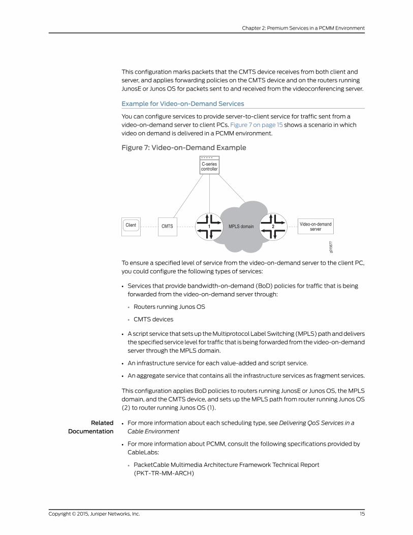
Example for Video-on-Demand Services
You can configure services to provide server-to-client service for traffic sent from a
video-on-demand server to client PCs. Figure 7 on page 15 shows a scenario in which
video on demand is delivered in a PCMM environment.
Figure 7: Video-on-Demand Example
To ensure a specified level of service from the video-on-demand server to the client PC,
you could configure the following types of services:
• Services that provide bandwidth-on-demand (BoD) policies for traffic that is being
forwarded from the video-on-demand server through:
• Routers running Junos OS
• CMTS devices
• A script service that sets up the Multiprotocol Label Switching (MPLS) path and delivers
the specified service level for traffic that is being forwarded from the video-on-demand
server through the MPLS domain.
• An infrastructure service for each value-added and script service.
• An aggregate service that contains all the infrastructure services as fragment services.
This configuration applies BoD policies to routers running JunosE or Junos OS, the MPLS
domain, and the CMTS device, and sets up the MPLS path from router running Junos OS
(2) to router running Junos OS (1).
RelatedDocumentation
For more information about each scheduling type, see Delivering QoS Services in a
Cable Environment
•
• For more information about PCMM, consult the following specifications provided by
CableLabs:
• PacketCable Multimedia Architecture Framework Technical Report
(PKT-TR-MM-ARCH)
15Copyright © 2015, Juniper Networks, Inc.
Chapter 2: Premium Services in a PCMM Environment

• PacketCable Multimedia Specification PKT-SP-MM-I03-051221
• PacketCable Security Specifications (PKT-SP-SEC)
• Using the SAE in a PCMM Environment on page 16
• Using the NIC Resolver in PCMM Environments on page 21
• Example: Providing Premium Services
Using the SAE in a PCMMEnvironment
The SAE uses the Common Open Policy Service (COPS) protocol as specified in the
PacketCable Multimedia Specification PKT-SP-MM-I03-051221 to manage
PCMM-compliant CMTS devices in a cable network environment. The SAE connects to
the CMTS device by using a COPS over Transmission Control Protocol (TCP) connection.
In cable environments, the SAE manages the connection to the CMTS device.
The CMTS device does not provide address requests or notify the SAE of new subscribers,
subscriber IP addresses, or any other attributes. IP address detection and all other
subscriber attributes are collected outside of the COPS connection to the CMTS device.
The SAE uses COPS only to push policies to the CMTS device and to learn about the
CMTS status and usage data.
Because the CMTS device does not have the concept of interfaces, the SRC software
uses pseudointerfaces to model CMTS subscriber connections similar to subscriber
connections for routers running Junos OS.
This section describes how the SAE is used in cable networks. It includes the following
topics:
• Logging In Subscribers and Creating Sessions on page 16
• SAE Communities on page 19
• Storing Session Data on page 20
Logging In Subscribers and Creating Sessions
You can use two mechanisms to obtain subscriber address requests and other information
and to set up a pseudointerface on the CMTS device. (You must choose one mechanism;
you cannot mix them.):
1. Assigned IP subscriber. The SAE learns about a subscriber through subscriber-initiated
activities, such as activating a service through the portal or through the Advanced
Services Gateway (ASG).
With this method, you use the assigned IP subscriber login type along with the network
interface collector (NIC) to map IP addresses to the SAE.
2. Event notification from an IP address manager. The SAE learns about subscribers
through notifications from an external IP address manager, such as a DHCP server or
a RADIUS server.
Copyright © 2015, Juniper Networks, Inc.16
Service Management in a PCMM Environment

With this method, you use the event notification application programming interface
(API). The API provides an interface to the IP address manager, and lets the IP address
manager notify the SAE of events such as IP address assignments.
Assigned IP Subscribers
With the assigned IP subscriber method of logging in subscribers and creating sessions,
the SRC software uses IP address pools along with NIC resolvers to provide mapping of
IP addresses to SAEs. You configure the static address pools or dynamically discovered
address pools in the virtual router configuration for a CMTS device. These pools are
published in the NIC. The NIC maps subscriber IP addresses in requests received through
the portal or Advanced Services Gateway to the SAE that currently manages that CMTS
device.
Login Interactions with Assigned IP Subscribers
This section describes login interactions for assigned IP subscribers. In the example shown
in Figure 8 on page 17, the subscriber activates a service through a portal. You could also
have the subscriber activate a service through the Advanced Services Gateway.
Figure 8: Login Interactions with Assigned IP Subscribers
The sequence of events for logging in and creating sessions for assigned IP subscribers
is:
1. The subscriber logs in to the portal.
2. The portal sends the subscriber’s IP address to the NIC.
3. Based on the IP address, the NIC looks up the subscriber’s SAE, CMTS device, and
interface name, and returns this information to the portal.
4. The portal sends a getSubscriber message to the SAE. The message includes the
subscriber’s IP address, CMTS device, and interface name.
5. The SAE creates an assigned IP subscriber and performs a subscriber login. Specifically,
it:
a. Runs the interface classification script and creates a pseudointerface for the PCMM
device driver.
• If it finds a default policy, it pushes the policy to the CMTS device.
17Copyright © 2015, Juniper Networks, Inc.
Chapter 2: Premium Services in a PCMM Environment

• If it does not find a default policy, it continues with the next steps.
b. Runs the subscriber classification script with the IP address of the subscriber. (Use
the ASSIGNEDIP login type in subscriber classification scripts.)
c. Loads the subscriber profile.
d. Runs the subscriber authorization plug-ins.
e. Runs the subscriber tracking plug-ins.
f. Creates a subscriber session and stores the session data in the session store file.
6. The SAE pushes service policies for the subscriber session to the CMTS device.
Because the SAE is not notified when the subscriber logs out, the assigned IP idle timer
begins when no service is active. The SAE removes the interface subscriber session when
the timeout period ends.
Event Notification from an IP Address Manager
With the event notification method of logging in subscribers and creating subscriber
sessions, the subscriber logs in to the CMTS device and obtains an IP address through
an address server, usually a DHCP server. The SAE receives notifications about the
subscriber, such as the subscriber’s IP address, from an event notification application
that is installed on the DHCP server.
To use this method of logging in subscribers, you can use the event notification API to
create the application that notifies the SAE when events occur between the DHCP server
and the CMTS device. You can also use Monitoring Agent, an application that was created
with the event notification API, and that monitors DHCP or RADIUS messages for DHCP
or RADIUS servers. See SRC PE Sample Applications Guide.
Login with Event Notification
This section describes login interactions using event notifications.
Figure 9: Login Interactions with Event Notification Application
The sequence of events for logging in subscribers and creating sessions is:
Copyright © 2015, Juniper Networks, Inc.18
Service Management in a PCMM Environment

1. The DHCP client in the subscriber’s computer sends a DHCP discover request to the
DHCP server.
2. The DHCP server sends a DHCP offer to the subscriber’s DHCP client.
3. The DHCP client sends a DHCP request to the DHCP server.
4. The DHCP server acknowledges the request by sending a DHCP Ack message to the
DHCP client.
5. The event notification application that is running on the DHCP server intercepts the
DHCP Ack message.
6. The event notification application sends an ipUp message to the SAE that notifies
the SAE that an IP address is up.
7. The SAE performs a subscriber login. Specifically, it:
a. Runs the interface classification script and creates a pseudointerface for the PCMM
device driver.
• If it finds a default policy, it pushes the policy to the CMTS device.
• If it does not find a default policy, it continues with the next steps.
b. Runs the subscriber classification script.
c. Loads the subscriber profile.
d. Runs the subscriber authorization plug-ins.
e. Runs the subscriber tracking plug-ins.
f. Creates a subscriber session and stores the session in the session store file.
8. The SAE provisions policies for the subscriber session on the CMTS device.
The ipUp event should be sent with a timeout set to the DHCP lease time. The DHCP
server sends an ipUp event for each Ack sent to the client. The SAE restarts the timeout
each time it receives an ipUp event.
If the client explicitly releases the DHCP address (that is, it sends a DHCP release event),
the DHCP server sends an ipDown event. If the client does not renew the address, the
lease expires on the DHCP server and the timeout expires on the SAE.
SAE Communities
For SAE redundancy in a cable network, you can have a community of two or more SAEs.
SAEs in a community are given the role of either active SAE or passive SAE. The active
SAE manages the connection to the CMTS device and keeps session data up to date
within the community. Figure 10 on page 20 shows a typical SAE community.
19Copyright © 2015, Juniper Networks, Inc.
Chapter 2: Premium Services in a PCMM Environment

Figure 10: SAE Community
When an SAE opens a connection to the CMTS device, it negotiates with other SAEs to
determine which SAE controls the CMTS device. The SAE community manager and
members of the community select the active SAE.
A passive SAE needs to take over as active SAE in any of the following cases:
• The active SAE shuts down or the connection between the CMTS device and the active
SAE goes down. In this case, the active SAE notifies the passive SAEs, and one of the
passive SAEs takes over as active SAE.
• A passive SAE does not receive a keepalive message from the active SAE within the
keepalive interval. In this case, the passive SAE attempts to become the active SAE.
Storing Session Data
To aid in recovering from an SAE failover, the SAE stores subscriber and service session
data. When the SAE manages a CMTS device, session data is stored locally in the SAE
host’s file system. The SRC component that controls the storage of session data on the
SAE is called the session store. The session store queues data and then writes the data
to session store files on the SAE host’s disk. Once the data is written to disk, it can survive
a server reboot.
For more information, see Fault Recovery.
PCMMRecord-Keeping Server Plug-In
To allow the SAE’s embedded policy server to communicate with a record-keeping server
(RKS) in a PCMM environment, you need to use the PCMM record-keeping server plug-in.
This plug-in is similar to the RADIUS accounting plug-ins, but it works with any RKS that
is compliant with the PCMM specification. The RKS plug-in supports additional attributes:
Application-Manager-ID, Request-Type, and Update-Reason. The plug-in sends all
requests to the RKS as Acct-Status-Type=Interim-Update.
RelatedDocumentation
PCMM Environment Overview on page 7•
• Using the NIC Resolver in PCMM Environments on page 21
• Configuring the SAE to Manage PCMM Devices (SRC CLI) on page 27
• Initially Configuring the SAE
Copyright © 2015, Juniper Networks, Inc.20
Service Management in a PCMM Environment

• Storing Subscriber and Service Session Data
Using the NIC Resolver in PCMMEnvironments
If you are using the NIC to map the subscriber IP address to the SAE, you need to configure
a NIC host. The NIC system uses IP address pools to map IP addresses to SAEs. You
configure the local address pools in the application manager configuration for a policy
server group. These pools are published in the NIC. The NIC maps subscriber IP addresses
in requests received through the portal or Advanced Services Gateway to the policy server
group that currently manages that CMTS device.
The OnePopPcmm sample configuration data supports this scenario for a PCMM
environment in which you use the assigned IP subscriber method to log in subscribers
and in which you use the NIC to determine the subscriber’s SAE. The OnePopPcmm
configuration supports one point of presence (POP). NIC replication can be used to
provide high availability. The realm for this configuration accommodates the situation
in which IP pools are configured locally on each application manager group object.
The resolution process takes a subscriber’s IP address as the key and returns a reference
to the SAE managing this subscriber as the value.
The following agents collect information for resolvers in this realm:
• Directory agent PoolVr collects and publishes information about the mappings of IP
pools to the policy server group.
• Directory agent VrSaeId collects and publishes information about the mappings of
policy server groups to SAEs.
RelatedDocumentation
• PCMM Environment Overview on page 7
• Using the SAE in a PCMM Environment on page 16
• Specifying Application Manager Identifiers for Policy Servers (C-Web Interface)
• Configuring the NIC (SRC CLI)
• OnePopPcmm Scenario
21Copyright © 2015, Juniper Networks, Inc.
Chapter 2: Premium Services in a PCMM Environment

Copyright © 2015, Juniper Networks, Inc.22
Service Management in a PCMM Environment

PART 2
Configuration
• Tasks for Configuring the SAE for a PCMM Environment on page 25
• Configuration Tasks for Adding Objects for CMTS Devices on page 41
23Copyright © 2015, Juniper Networks, Inc.

Copyright © 2015, Juniper Networks, Inc.24
Service Management in a PCMM Environment

CHAPTER 3
Tasks for Configuring the SAE for a PCMMEnvironment
• Configuring the SAE for a Cable Network Environment (SRC CLI) on page 25
• Configuring the SAE for a Cable Network Environment (C-Web Interface) on page 26
• Configuring the SAE to Manage PCMM Devices (SRC CLI) on page 27
• Configuring the SAE to Manage PCMM Devices (C-Web Interface) on page 30
• Setting Up SAE Communities (SRC CLI) on page 30
• Setting Up SAE Communities (C-Web Interface) on page 31
• Configuring the SAE Community Manager on page 31
• Configuring the SAE Community Manager (C-Web Interface) on page 33
• Configuring SAE Properties for the Event Notification API (SRC CLI) on page 33
• Configuring SAE Properties for the Event Notification API (C-Web Interface) on page 34
• Configuring Record-Keeping Server Peers for Plug-Ins (SRC CLI) on page 34
• Configuring Record-Keeping Server Peers for Plug-Ins (C-Web Interface) on page 35
• Configuring PCMM Record-Keeping Server Plug-Ins (SRC CLI) on page 36
• Configuring PCMM Record-Keeping Server Plug-Ins (C-Web Interface) on page 38
• Configuring CMTS-Specific RKS Plug-Ins (SRC CLI) on page 38
• Configuring CMTS-Specific RKS Plug-Ins (C-Web Interface) on page 39
Configuring the SAE for a Cable Network Environment (SRC CLI)
The tasks to configure the SAE for a cable network environment are:
1. Configure the SAE to manage PCMM devices.
“Configuring the SAE to Manage PCMM Devices (SRC CLI)” on page 27.
2. Configure the session store.
See Configuring the Session Store Feature (SRC CLI).
3. Set up SAE communities.
See “Setting Up SAE Communities (SRC CLI)” on page 30.
25Copyright © 2015, Juniper Networks, Inc.

4. (Optional) Configure SAE properties for the event notification API.
See “Configuring SAE Properties for the Event Notification API (SRC CLI)” on page 33
(if you are using an external address manager).
5. (Optional) Configure record-keeping server peers for plug-ins.
See “Configuring Record-Keeping Server Peers for Plug-Ins (SRC CLI)” on page 34 (if
you are using the RKS plug-in).
6. (Optional) Configure PCMM record-keeping server plug-ins.
See “Configuring PCMM Record-Keeping Server Plug-Ins (SRC CLI)” on page 36 (if
you are using the SAE’s embedded policy server).
7. (Optional) Configure CMTS-specific RKS plug-ins.
See “Configuring CMTS-Specific RKS Plug-Ins (SRC CLI)” on page 38.
In addition to configuring the SAE, you need to:
1. Configure the CMTS device in the directory (if you are using the SAE’s embedded
policy server).
See “Adding Objects for CMTS Devices (SRC CLI)” on page 41.
2. Configure the NIC (if you are using assigned IP subscribers).
See Using the NIC Resolver.
3. Enable the Common Open Policy Service (COPS) interface on the CMTS device. See
the documentation for your CMTS device for information about how to do this.
RelatedDocumentation
PCMM Environment Overview on page 7•
• Configuring the SAE for a Cable Network Environment (C-Web Interface) on page 26
• Configuring the SAE to Manage PCMM Devices (C-Web Interface) on page 30
• Configuring an SAE Group
Configuring the SAE for a Cable Network Environment (C-Web Interface)
The tasks to configure the SAE for a cable network environment are:
1. Configure the SAE to manage PCMM devices.
See “Configuring the SAE to Manage PCMM Devices (C-Web Interface)” on page 30.
2. Configure the session store.
3. Set up SAE communities.
See Setting Up SAE Communities (C-Web Interface).
4. (Optional) Configure SAE properties for the Event Notification API.
See “Configuring SAE Properties for the Event Notification API (C-Web Interface)” on
page 34 (if you are using an external address manager).
Copyright © 2015, Juniper Networks, Inc.26
Service Management in a PCMM Environment

5. (Optional) Configure record-keeping server peers for plug-ins.
See “Configuring Record-Keeping Server Peers for Plug-Ins (C-Web Interface)” on
page 35 (if you are using the RKS plug-in).
6. (Optional) Configure PCMM record-keeping server plug-ins.
See “Configuring PCMM Record-Keeping Server Plug-Ins (C-Web Interface)” on
page 38 (if you are using the SAE’s embedded policy server).
In addition to configuring the SAE, you need to:
1. Configure the CMTS device in the directory (if you are using the SAE’s embedded
policy server).
See “Adding Objects for CMTS Devices (C-Web Interface)” on page 42.
2. Configure the NIC (if you are using assigned IP subscribers).
See “Using the NIC Resolver in PCMM Environments” on page 21.
3. Enable the Common Open Policy Service (COPS) interface on the CMTS device. See
the documentation for your CMTS device for information about how to do this.
RelatedDocumentation
Configuring the SAE for a Cable Network Environment (SRC CLI) on page 25•
• Using the SAE in a PCMM Environment on page 16
• PCMM Environment Overview on page 7
Configuring the SAE toManage PCMMDevices (SRC CLI)
The SAE connects to the PCMM device by using a COPS over TCP connection. The PCMM
device driver controls this connection.
Use the following configuration statements to configure the SAE to manage CMTS
devices:
shared sae configuration driver pcmm {keepalive-interval keepalive-interval ;tcp-connection-timeout tcp-connection-timeout ;application-manager-id application-manager-id ;message-timeoutmessage-timeout ;cops-message-maximum-length cops-message-maximum-length ;cops-message-read-buffer-size cops-message-read-buffer-size ;cops-message-write-buffer-size cops-message-write-buffer-size ;sae-community-manager sae-community-manager ;disable-full-sync disable-full-sync ;disable-pcmm-i03-policy disable-pcmm-i03-policy ;session-recovery-retry-interval session-recovery-retry-interval ;element-id element-id ;default-rks-plug-in default-rks-plug-in ;
}
To configure the SAE to manage CMTS devices:
27Copyright © 2015, Juniper Networks, Inc.
Chapter 3: Tasks for Configuring the SAE for a PCMM Environment

1. From configuration mode, access the configuration statement that configures the
PCMM driver. In this sample procedure, the PCMM device driver is configured in the
west-region group.
user@host# edit shared sae groupwest-region configuration driver pcmm
2. Configure the interval between keepalive messages sent from the COPS client (the
PCMM device) to the COPS server (the SAE).
[edit shared sae group west-region configuration driver pcmm]user@host# set keepalive-interval keepalive-interval
3. Configure the timeout for opening a TCP connection to the PCMM device.
[edit shared sae group west-region configuration driver pcmm]user@host# set tcp-connection-timeout tcp-connection-timeout
4. When this SAE is configured as the application manager, configure the identifier of
the application manager.
[edit shared sae group west-region configuration driver pcmm]user@host# set application-manager-id application-manager-id
5. Configure the time that the COPS server (the SAE) waits for a response to COPS
requests from the COPS client (the PCMM device). Change this value only if a high
number of COPS timeout events appear in the error log.
[edit shared sae group west-region configuration driver pcmm]user@host# setmessage-timeoutmessage-timeout
6. Configure the maximum length of a COPS message.
[edit shared sae group west-region configuration driver pcmm]user@host# set cops-message-maximum-length cops-message-maximum-length
7. Configure the buffer size for receiving COPS messages from the COPS client.
[edit shared sae group west-region configuration driver pcmm]user@host# set cops-message-read-buffer-size cops-message-read-buffer-size
8. Configure the buffer size for sending COPS messages to the COPS client.
[edit shared sae group west-region configuration driver pcmm]user@host# set cops-message-write-buffer-size cops-message-write-buffer-size
9. Configure the name of the community manager that manages PCMM driver
communities. Active SAEs are selected from this community.
[edit shared sae group west-region configuration driver pcmm]user@host# set sae-community-manager sae-community-manager
10. Enable or disable state synchronization with PCMM policy servers.
[edit shared sae group west-region configuration driver pcmm]user@host# set disable-full-sync disable-full-sync
Copyright © 2015, Juniper Networks, Inc.28
Service Management in a PCMM Environment

11. Enable or disable the SAE to send classifiers to the router that comply with PCMM
IO3. Disable this option if your network deployment has CMTS devices that do not
support PCMM IO3.
[edit shared sae group west-region configuration driver pcmm]user@host# set disable-pcmm-i03-policy disable-pcmm-i03-policy
12. Configure the time between attempts by the SAE to restore service sessions that are
being recovered in the background when state synchronization completes with a
state-data-incomplete error.
[edit shared sae group west-region configuration driver pcmm]user@host# set session-recovery-retry-interval session-recovery-retry-interval
13. (Optional) Configure the unique identifier that the SAE uses to identify itself when it
originates in record-keeping server (RKS) events.
[edit shared sae group west-region configuration driver pcmm]user@host# set element-id element-id
14. (Optional) Specify the name of the default RKS plug-in to which the SAE sends events
for CMTS devices.
[edit shared sae group west-region configuration driver pcmm]user@host# set default-rks-plug-in default-rks-plug-in
15. (Optional) Verify your PCMM driver configuration.
[edit shared sae group west-region configuration driver pcmm]user@host# showkeepalive-interval 45;tcp-connection-timeout 5;application-manager-id 1;message-timeout 120000;cops-message-maximum-length 204800;cops-message-read-buffer-size 3000;cops-message-write-buffer-size 3000;sae-community-manager PcmmCommunityManager;disable-full-sync true;disable-pcmm-i03-policy true;session-recovery-retry-interval 3600000;element-id 1;default-rks-plug-in rksTracking;
RelatedDocumentation
Using the SAE in a PCMM Environment on page 16•
• Connections to Managed Devices
• Configuring the SAE to Manage PCMM Devices (C-Web Interface) on page 30
• Configuring CMTS-Specific RKS Plug-Ins (SRC CLI) on page 38
• Initially Configuring the SAE
29Copyright © 2015, Juniper Networks, Inc.
Chapter 3: Tasks for Configuring the SAE for a PCMM Environment

Configuring the SAE toManage PCMMDevices (C-Web Interface)
The SAE connects to the PCMM device by using a COPS over TCP connection. The PCMM
device driver controls this connection.
To configure the SAE to manage PCMM devices:
1. Click Configure, expand Shared>SAE>Configuration>Driver, and then click PCCM.
The PCCM pane appears.
2. Click Create, enter information as described in the Help text in the main pane, and
then click Apply.
RelatedDocumentation
For information about setting up SAE groups, see Configuring an SAE Group•
• Configuring the SAE to Manage PCMM Devices (SRC CLI) on page 27
• Configuring PCMM Record-Keeping Server Plug-Ins (SRC CLI) on page 36
• Using the SAE in a PCMM Environment on page 16
Setting Up SAE Communities (SRC CLI)
You can configure the following for SAE communities:
• Define the members of an SAE community by adding the IP addresses of SAEs in the
community to the virtual router object of the network device in the directory.
See “Creating Virtual Routers for the CMTS Device (SRC CLI)” on page 43.
• Configure parameters for the SAE community manager.
See “Configuring the SAE Community Manager” on page 31.
• Specify the name of the community manager with the set sae-community-manager
option in the PCMM driver configuration.
See “Configuring the SAE to Manage PCMM Devices (SRC CLI)” on page 27.
• If there is a firewall in the network, configure the firewall to allow SAE messages through.
RelatedDocumentation
Using the SAE in a PCMM Environment on page 16•
• Setting Up SAE Communities (C-Web Interface)
• Initially Configuring the SAE
• Configuring SAE Properties for the Event Notification API (SRC CLI) on page 33
Copyright © 2015, Juniper Networks, Inc.30
Service Management in a PCMM Environment

Setting Up SAE Communities (C-Web Interface)
Tasks to configure SAE communities are:
• Configuring the SAE Community Manager on page 31
• Specifying the Community Manager in the SAE Device Driver on page 31
Configuring the SAE Community Manager
To configure the SAE community manager that manages third-party device communities:
1. Click Configure, expand Shared>SAE, and then click the SAE group for which you
want to manage third-party devices.
The Group pane appears.
2. In the side pane, expand Configuration>External Interface Features:PCMMCommunityManager, and then click Community Manager.
The Community Manager pane appears.
3. Enter information as described in the Help text in the main pane, and click Apply.
Specifying the Community Manager in the SAE Device Driver
To specify the community manager in the SAE device driver:
1. Click Configure, expand Shared>SAE>Configuration>Driver, and then click ThirdParty.
The Third Party pane appears.
2. Click Create, enter information as described in the Help text in the main pane, and
then click Apply.
RelatedDocumentation
Setting Up SAE Communities (SRC CLI)•
• Setting Up Script Services
• Adding Objects for Network Devices (C-Web Interface)
Configuring the SAE Community Manager
Use the following configuration statements to configure the SAE community manager
that manages PCMM device communities:
shared sae configuration external-interface-features name CommunityManager {keepalive-interval keepalive-interval ;threads threads ;acquire-timeout acquire-timeout ;blackout-time blackout-time ;
}
To configure the community manager:
31Copyright © 2015, Juniper Networks, Inc.
Chapter 3: Tasks for Configuring the SAE for a PCMM Environment

1. From configuration mode, access the configuration statements for the community
manager. In this sample procedure, west_region is the name of the SAE group, and
sae_mgr is the name of the community manager.
user@host# edit shared sae groupwest-region configurationexternal-interface-features sae_mgr CommunityManager
2. Specify the interval between keepalive messages sent from the active SAE to the
passive members of the community.
[edit shared sae group west-region configuration external-interface-features sae_mgrCommunityManager]
user@host# set keepalive-interval keepalive-interval
3. Specify the number of threads that are allocated to manage the community. You
generally do not need to change this value.
[edit shared sae group west-region configuration external-interface-features sae_mgrCommunityManager]
user@host# set threads threads
4. Specify the amount of time an SAE waits for a remote member of the community
when it is acquiring a distributed lock. You generally do not need to change this value.
[edit shared sae group west-region configuration external-interface-features sae_mgrCommunityManager]
user@host# set acquire-timeout acquire-timeout
5. Specify the amount of time that an active SAE must wait after it shuts down before
it can try to become the active SAE of the community again.
[edit shared sae group west-region configuration external-interface-features sae_mgrCommunityManager]
user@host# set blackout-time blackout-time
6. (Optional) Verify the configuration of the SAE community manager.
[edit shared sae group west-region configuration external-interface-features sae_mgr CommunityManager] user@host# showCommunityManager { keepalive-interval 30; threads 5; acquire-timeout 15; blackout-time 30;}
RelatedDocumentation
Using the SAE in a PCMM Environment on page 16•
• Configuring the SAE Community Manager (C-Web Interface) on page 33
• Setting Up SAE Communities (SRC CLI) on page 30
• Initially Configuring the SAE
Copyright © 2015, Juniper Networks, Inc.32
Service Management in a PCMM Environment

Configuring the SAE Community Manager (C-Web Interface)
To configure the SAE community manager that manages PCMM device communities:
1. Click Configure, expand Shared>SAE, and then expand the SAE group for which you
want to manage PCMM devices.
2. In the side pane, expand Configuration>External Interface Features:PCMMCommunityManager, and then click Community Manager.
The Community pane appears.
3. Enter information as described in the Help text in the main pane, and click Apply.
RelatedDocumentation
For information about setting up SAE groups, see Configuring an SAE Group•
• Setting Up SAE Communities (C-Web Interface)
• Configuring the SAE Community Manager on page 31
• Using the SAE in a PCMM Environment on page 16
Configuring SAE Properties for the Event Notification API (SRC CLI)
Use the following configuration statements to configure properties for the Event
Notification API:
shared sae configuration external-interface-features name EventAPI {retry-time retry-time ;retry-limit retry-limit ;threads threads ;
}
To configure properties for the Event Notification API:
1. From configuration mode, access the configuration statements for the Event
Notification API. In this sample procedure, west-region is the name of the SAE group,
and event_api is the name of the Event API configuration.
user@host# edit shared sae groupwest-region configurationexternal-interface-features event_api EventAPI
2. Specify the amount of time between attempts to send events that could not be
delivered.
[edit shared saegroupwest-region configuration external-interface-features event_apiEventAPI]
user@host# set retry-time retry-time
3. Specify the number of times an event fails to be delivered before the event is discarded.
[edit shared saegroupwest-region configuration external-interface-features event_apiEventAPI]
user@host# set retry-limit retry-limit
33Copyright © 2015, Juniper Networks, Inc.
Chapter 3: Tasks for Configuring the SAE for a PCMM Environment

4. Specify the number of threads allocated to process events.
[edit shared saegroupwest-region configuration external-interface-features event_apiEventAPI]
user@host# set threads threads
5. (Optional) Verify the configuration of the Event Notification API properties.
[edit shared sae group west-region configuration external-interface-features event_api EventAPI] user@host# showEventAPI { retry-time 300; retry-limit 5; threads 5;}
RelatedDocumentation
Using the SAE in a PCMM Environment on page 16•
• Configuring SAE Properties for the Event Notification API (C-Web Interface) on page 34
• Initially Configuring the SAE
• Configuring the SAE to Manage PCMM Devices (SRC CLI) on page 27
Configuring SAE Properties for the Event Notification API (C-Web Interface)
To configure properties for the event notification API:
1. Click Configure, expand Shared>SAE, and then expand the SAE group for which you
want to manage devices.
2. In the side pane, expandConfiguration>External InterfaceFeatures: event, and then
click Event API.
The Event API pane appears.
3. Enter information as described in the Help text in the main pane, and click Apply.
RelatedDocumentation
Configuring an SAE Group•
• Configuring SAE Properties for the Event Notification API (SRC CLI) on page 33
Configuring Record-Keeping Server Peers for Plug-Ins (SRC CLI)
An RKS peer is an instance of an RKS. A PCMM environment has a primary RKS and
optionally a secondary RKS. The primary RKS is mandatory, and you assign the RKS as
primary by configuring it as the default peer in the RKS plug-in. The secondary RKS is
optional, and it is an RKS peer that is not configured as the default peer. If you define
multiple nondefault peers, one of them is randomly chosen to be the secondary RKS.
RKS peers are configured in the peer group for each PCMM RKS plug-in instance. To
create an RKS peer group:
Copyright © 2015, Juniper Networks, Inc.34
Service Management in a PCMM Environment

Use the following configuration statements to configure an RKS peer group.
shared sae configuration plug-ins name name pcmm-rks peer-group name {server-address server-address ;server-port server-port ;
}
To configure an RKS peer group:
1. From configuration mode, access the configuration statements for RKS plug-ins. In
this sample procedure, west-region is the name of the SAE group, and rksPlugin is the
name of the plug-in and rksPeer is the name of the peer group.
user@host# edit shared sae groupwest-region configuration plug-ins name rksPluginpcmm-rks peer-group rksPeer
2. Specify the IP address of the RKS server to which the SAE sends accounting data.
[edit shared sae group west-region configuration plug-ins name rksPlugin pcmm-rkspeer-group rksPeer]
user@host# set server-address server-address
3. Specify the port used for sending accounting packets.
[edit shared sae group west-region configuration plug-ins name rksPlugin pcmm-rkspeer-group rksPeer]
user@host# set server-port server-port
4. (Optional) Verify your configuration.
[edit shared sae group west-region configuration plug-ins name rksPlugin pcmm-rks peer-group rksPeer]user@host# showserver-address 10.10.3.60;server-port 1812;
RelatedDocumentation
Using the SAE in a PCMM Environment on page 16•
• Configuring Record-Keeping Server Peers for Plug-Ins (C-Web Interface) on page 35
• Configuring PCMM Record-Keeping Server Plug-Ins (SRC CLI) on page 36
• Configuring CMTS-Specific RKS Plug-Ins (SRC CLI) on page 38
• Initially Configuring the SAE
Configuring Record-Keeping Server Peers for Plug-Ins (C-Web Interface)
An RKS peer is an instance of a record-keeping server. A PCMM environment has a primary
RKS and optionally a secondary RKS. The primary RKS is mandatory, and you assign the
RKS as primary by configuring it as the default peer in the RKS plug-in. The secondary
RKS is optional, and it is an RKS peer that is not configured as the default peer. If you
define multiple nondefault peers, one of them is randomly chosen to be the secondary
RKS.
35Copyright © 2015, Juniper Networks, Inc.
Chapter 3: Tasks for Configuring the SAE for a PCMM Environment

RKS peers are configured in the peer group for each PCMM RKS plug-in instance. To
create an RKS peer group:
1. Click Configure, expand Shared>SAE, and then expand the SAE group for which you
want to create RKS plug-ins.
2. In the side pane, expand Configuration>Plug Ins.
3. Expand the plug-in that you created for RKS, and then click PCMMRKS.
4. Enter information as described in the Help text in the main pane, and click Apply.
RelatedDocumentation
Configuring Record-Keeping Server Peers for Plug-Ins (SRC CLI) on page 34•
• Configuring PCMM Record-Keeping Server Plug-Ins (C-Web Interface) on page 38
• Configuring PCMM Record-Keeping Server Plug-Ins (SRC CLI) on page 36
Configuring PCMMRecord-Keeping Server Plug-Ins (SRC CLI)
Use the following configuration statements to configure an RKS plug-in.
shared sae configuration plug-ins name name pcmm-rks {load-balancing-mode (failover | roundRobin);failback-timer failback-timer;retry-interval retry-interval ;maximum-queue-lengthmaximum-queue-length ;bind-address bind-address ;udp-port udp-port ;feid-mso-data feid-mso-data ;feid-mso-domain-name feid-mso-domain-name ;trusted-element;default-peer default-peer ;
}
To configure an RKS plug-in:
1. From configuration mode, access the configuration statements for RKS plug-ins. In
this sample procedure, west-region is the name of the SAE group, and rksPlugin is the
name of the plug-in.
user@host# edit shared sae groupwest-region configuration plug-ins name rksPluginpcmm-rks
2. Specify the mode for load-balancing RKSs.
[edit shared sae group west-region configuration plug-ins name rksPlugin pcmm-rks]user@host# set load-balancing-mode (failover | roundRobin)
3. Specify if and when the SAE attempts to fail back to the default peer.
[edit shared sae group west-region configuration plug-ins name rksPlugin pcmm-rks]user@host# set failback-timer failback-timer
Copyright © 2015, Juniper Networks, Inc.36
Service Management in a PCMM Environment

4. Specify the time the SAE waits for a response from an RKS before it resends the
packet.
[edit shared sae group west-region configuration plug-ins name rksPlugin pcmm-rks]user@host# set retry-interval retry-interval
5. Specify the maximum number of unacknowledged messages that the plug-in receives
from the RKS before it discards new messages.
[edit shared sae group west-region configuration plug-ins name rksPlugin pcmm-rks]user@host# setmaximum-queue-lengthmaximum-queue-length
6. (Optional) Specify the source IP address that the plug-in uses to communicate with
the RKS.
[edit shared sae group west-region configuration plug-ins name rksPlugin pcmm-rks]user@host# set bind-address bind-address
7. (Optional) Specify the source UDP port or a pool of ports that the plug-in uses to
communicate with the RKS.
[edit shared sae group west-region configuration plug-ins name rksPlugin pcmm-rks]user@host# set udp-port udp-port
8. (Optional) Specify the multiple service operator (MSO)—defined data in the financial
entity ID (FEID) attribute, which is included in event messages.
[edit shared sae group west-region configuration plug-ins name rksPlugin pcmm-rks]user@host# set feid-mso-data feid-mso-data
9. (Optional) Specify the MSO domain name in the FEID attribute that uniquely identifies
the MSO for billing and settlement purposes.
[edit shared sae group west-region configuration plug-ins name rksPlugin pcmm-rks]user@host# set feid-mso-domain-name feid-mso-domain-name
10. (Optional) When the SAE is running as a policy server—which means that the SAE
sends event messages directly to the RKS—enable the SAE as a trusted network
element.
[edit shared sae group west-region configuration plug-ins name rksPlugin pcmm-rks]user@host# set trusted-element
11. Specify the name of the primary RKS peer to which the SAE sends accounting packets.
See “Configuring Record-Keeping Server Peers for Plug-Ins (SRC CLI)” on page 34.
[edit shared sae group west-region configuration plug-ins name rksPlugin pcmm-rks]user@host# set default-peer default-peer
12. (Optional) Verify your RKS plug-in configuration.
[edit shared sae group west-region configuration plug-ins name rksPlugin pcmm-rks]user@host> show
37Copyright © 2015, Juniper Networks, Inc.
Chapter 3: Tasks for Configuring the SAE for a PCMM Environment

load-balancing-mode failover;failback-timer -1;retry-interval 3000;maximum-queue-length 10000;feid-mso-domain-name abcd.com;trusted-element;default-peer radius01;
13. (Optional) Specify an RKS plug-in for specific CMTS devices.
See “Configuring CMTS-Specific RKS Plug-Ins (SRC CLI)” on page 38.
RelatedDocumentation
Using the SAE in a PCMM Environment on page 16•
• PCMM Environment Overview on page 7
• Configuring PCMM Record-Keeping Server Plug-Ins (C-Web Interface) on page 38
• Initially Configuring the SAE
Configuring PCMMRecord-Keeping Server Plug-Ins (C-Web Interface)
To configure an RKS plug-in:
1. Click Configure, expand Shared>SAE, and then expand the SAE group for which you
want to create RKS plug-ins,
2. In the side pane, expand Configuration>Plug Ins.
3. Expand the plug-in that you created for RKS, and then click PCMMRKS.
4. Click Create, enter information as described in the Help text in the main pane, and
then click Apply.
RelatedDocumentation
Configuring an SAE Group•
• Configuring PCMM Record-Keeping Server Plug-Ins (SRC CLI) on page 36
• Configuring Record-Keeping Server Peers for Plug-Ins (C-Web Interface) on page 35
• Using the SAE in a PCMM Environment on page 16
Configuring CMTS-Specific RKS Plug-Ins (SRC CLI)
You can configure an RKS plug-in for specific CMTS devices. When there are events for
the CMTS device, the SAE sends the events to the specified plug-in.
Use the following configuration statement to assign a CMTS-specific RKS plug-in.
shared sae configuration driver pcmm cmts-specific-rks-plug-ins name {rks-plug-in rks-plug-in ;
}
To configure a CMTS-specific RKS plug-in:
Copyright © 2015, Juniper Networks, Inc.38
Service Management in a PCMM Environment

1. From configuration mode, access the configuration statements for RKS plug-ins. In
this sample procedure, west-region is the name of the SAE group, and cmtsPlugin is
the name of the plug-in assignment.
user@host# edit shared sae groupwest-region configuration driver pcmmcmts-specific-rks-plug-ins cmtsPlugin
2. Specify the name of the CMTS-specific RKS plug-in.
[edit sharedsaegroupwest-regionconfigurationdriverpcmmcmts-specific-rks-plug-inscmtsPlugin]
user@host# set rks-plug-in rks-plug-in
3. (Optional) Verify your configuration.
[edit shared sae group west-region configuration driver pcmm cmts-specific-rks-plug-ins cmtsPlugin]user@host# showrks-plug-in rksPlugin;
RelatedDocumentation
Configuring CMTS-Specific RKS Plug-Ins (C-Web Interface) on page 39•
• Configuring Record-Keeping Server Peers for Plug-Ins (SRC CLI) on page 34
• Configuring PCMM Record-Keeping Server Plug-Ins (SRC CLI) on page 36
• Adding Objects for CMTS Devices (SRC CLI) on page 41
• Initially Configuring the SAE
Configuring CMTS-Specific RKS Plug-Ins (C-Web Interface)
You can configure an RKS plug-in for specific CMTS devices. When there are events for
the CMTS device, the SAE sends the events to the specified plug-in.
To configure a CMTS-specific RKS plug-in:
1. Click Configure, expand Shared>SAE,>Configuration>Driver, and then click PCCM.
2. Click Configure, expand Shared>SAE, and then expand the SAE group for which you
want to create CMTS-specific RKS plug-ins.
3. In the side pane, expand Configuration>Drivers, and then click PCCM.
The PCMM pane appears.
4. From the Create new list, select CMTS Specific RKS Plug-Ins.
5. Type a name for the new plug-in in the dialog box, and click OK.
6. In the side pane, click the new plug-in.
7. Click Create, enter information as described in the Help text in the main pane, and
then click Apply.
39Copyright © 2015, Juniper Networks, Inc.
Chapter 3: Tasks for Configuring the SAE for a PCMM Environment

RelatedDocumentation
• Configuring CMTS-Specific RKS Plug-Ins (SRC CLI) on page 38
• Adding Objects for CMTS Devices (SRC CLI) on page 41
• Creating Virtual Routers for the CMTS Device (SRC CLI) on page 43
Copyright © 2015, Juniper Networks, Inc.40
Service Management in a PCMM Environment

CHAPTER 4
Configuration Tasks for Adding Objectsfor CMTS Devices
• Adding Objects for CMTS Devices (SRC CLI) on page 41
• Adding Objects for CMTS Devices (C-Web Interface) on page 42
• Creating Virtual Routers for the CMTS Device (SRC CLI) on page 43
• Creating Virtual Routers for the CMTS Device (C-Web Interface) on page 44
Adding Objects for CMTS Devices (SRC CLI)
To manage CMTS devices, the SAE creates and manages pseudointerfaces that it
associates with a virtual router object. Each CMTS device in the SRC network must appear
in the configuration as a router object, and it must be associated with a virtual router
object called default. The router and virtual router are not actually configured on the
CMTS device; the router and virtual router provide a way for the SAE to manage the CMTS
device by using the SAE’s embedded policy server.
Use the following configuration statements to add a router object:
shared network device name {description description ;management-addressmanagement-address ;device-type (junose | junos | pcmm | proxy);qos-profile [ qos-profile ...];
}
To add a router:
1. From configuration mode, access the configuration statements that configure network
devices. In this sample procedure, pcmm_dtr is the name of the object.
user@host# edit shared network device pcmm_dtr
2. (Optional) Add a description for the CMTS device.
[edit shared network device pcmm_dtr]user@host# set description description
3. Add the IP address of the CMTS device.
41Copyright © 2015, Juniper Networks, Inc.

[edit shared network device pcmm_dtr]user@host# setmanagement-addressmanagement-address
4. (Optional) Specify the type of device that you are adding.
[edit shared network device pcmm_dtr]user@host# set device-type pcmm
5. (Optional) Verify your configuration.
[edit shared network device pcmm_dtr] user@host# showdescription "CMTS device";management-address 192.168.3.5;device-type pcmm;interface-classifier { rule rule-0 { script #; }}
RelatedDocumentation
Connections to Managed Devices•
• Configuring CMTS-Specific RKS Plug-Ins (SRC CLI) on page 38
• Creating Virtual Routers for the CMTS Device (SRC CLI) on page 43
Adding Objects for CMTS Devices (C-Web Interface)
To manage CMTS devices, the SAE creates and manages pseudointerfaces that it
associates with a virtual router object. Each CMTS device in the SRC network must appear
in the configuration as a router object, and it must be associated with a virtual router
object called default. The router and virtual router are not actually configured on the
CMTS device; the router and virtual router provide a way for the SAE to manage the CMTS
device by using the SAE’s embedded policy server.
To add a router:
1. Click Configure, expand Shared, and then click Network.
The Shared Network pane appears.
2. From the Create new list, select Device.
3. Type a name for the new device in the dialog box, and click OK.
The Device pane appears.
4. From the Device Type list, select pccm.
5. Enter information as described in the Help text in the main pane, and click Apply.
RelatedDocumentation
Creating Virtual Routers for the CMTS Device (C-Web Interface) on page 44•
Copyright © 2015, Juniper Networks, Inc.42
Service Management in a PCMM Environment

Creating Virtual Routers for the CMTSDevice (SRC CLI)
You need to add a virtual router object called default to the CMTS device.
Use the following configuration statements to add a virtual router:
shared network device name virtual-router name {sae-connection [ sae-connection ...];snmp-read-community snmp-read-community ;snmp-write-community snmp-write-community ;scope [ scope ...];local-address-pools local-address-pools ;static-address-pools static-address-pools ;tracking-plug-in [ tracking-plug-in ...];
}
To add a virtual router:
1. From configuration mode, access the configuration statements for virtual routers. In
this sample procedure, pcmm_dtr is the name of the router and default is the name
of the virtual router.
user@host# edit shared network device pcmm_dtr virtual-router default
2. Specify the addresses of SAEs that can manage this router. This step is required for
the SAE to work with the router.
[edit shared network device pcmm_dtr virtual-router default]user@host# set sae-connection [ sae-connection ...]
To specify the active SAE and the redundant SAE, enter an exclamation point (!) after
the hostname or IP address of the connected SAE. For example:
[edit shared network device pcmm_dtr virtual-router default]user@host# set sae-connection [sae1! sae2!]
3. (Optional) Specify an SNMP community name for SNMP read-only operations for
this VR.
[edit shared network device pcmm_dtr virtual-router default]user@host# set snmp-read-community snmp-read-community
4. (Optional) Specify an SNMP community name for SNMP write operations for this
virtual router.
[edit shared network device pcmm_dtr virtual-router default]user@host# set snmp-write-community snmp-write-community
5. (Optional) Specify service scopes assigned to this virtual router.
See Configuring Service Scopes (SRC CLI).
[edit shared network device pcmm_dtr virtual-router default]user@host# set scope [ scope ...]
43Copyright © 2015, Juniper Networks, Inc.
Chapter 4: Configuration Tasks for Adding Objects for CMTS Devices

6. (Optional) Specify the list of IP address pools that a CMTS virtual router currently
manages and stores.
If you are using assigned IP subscribers along with the network information collector
(NIC), you need to configure either a local or static address pool so that the NIC can
resolve the IP-to-SAE mapping.
[edit shared network device pcmm_dtr virtual-router default]user@host# set local-address-pools local-address-pools
7. (Optional) Specify the list of IP address pools that a CMTS VR manages but does not
store.
If you are using assigned IP subscribers along with the NIC, you need to configure either
a local or static address pool so that the NIC can resolve the IP-to-SAE mapping.
[edit shared network device pcmm_dtr virtual-router default]user@host# set static-address-pools static-address-pools
8. (Optional) Specify the plug-ins that track interfaces that the SAE manages on this
virtual router.
[edit shared network device pcmm_dtr virtual-router default]user@host# tracking-plug-in [ tracking-plug-in ...]
9. (Optional) Verify your configuration.
[edit shared network device pcmm_dtr virtual-router default] user@host# showsae-connection [ 10.14.39.2 10.10.5.30 ];snmp-read-community ********;snmp-write-community ********;scope POP-Westford;local-address-pools "10.25.8.0 10.25.20.255";tracking-plug-in rksPlugin;
RelatedDocumentation
Adding Objects for CMTS Devices (SRC CLI) on page 41•
• Configuring CMTS-Specific RKS Plug-Ins (SRC CLI) on page 38
• Associating Security Names with a Community (SRC CLI)
Creating Virtual Routers for the CMTSDevice (C-Web Interface)
You need to add a virtual router object called default to the CMTS device.
To add a virtual router to an existing router:
1. Click Configure, expand Shared>Network, and then click a CMTS device.
The Device pane appears.
2. From the Create new list, select Virtual Router.
3. Type a name for the new device in the dialog box, and click OK.
Copyright © 2015, Juniper Networks, Inc.44
Service Management in a PCMM Environment

The Virtual Router pane appears.
4. Click Create, enter information as described in the Help text in the main pane, and
then click Apply.
RelatedDocumentation
• Adding Objects for CMTS Devices (C-Web Interface) on page 42
45Copyright © 2015, Juniper Networks, Inc.
Chapter 4: Configuration Tasks for Adding Objects for CMTS Devices

Copyright © 2015, Juniper Networks, Inc.46
Service Management in a PCMM Environment

PART 3
Index
• Index on page 49
47Copyright © 2015, Juniper Networks, Inc.

Copyright © 2015, Juniper Networks, Inc.48
Service Management in a PCMM Environment

Index
Aaddress pools. See IP address pools
application manager
role, in PCMM environment...........................................7
assigned IP subscribers
PCMM network.........................................................16, 43
IP address pools.....................................................16
Ccable modem termination system. See CMTS
devices
client type 1, PCMM..................................................................9
client type 2, PCMM................................................................10
CMTS devices
adding objects to directory
C-Web interface.....................................................42
SRC CLI......................................................................41
adding virtual router objects to directory
C-Web interface....................................................44
SRC CLI.....................................................................43
configuration statements......................41, 42, 43, 44
role..........................................................................................7
community manager
configuring, third-party devices
C-Web interface......................................................31
conventions
notice icons.........................................................................x
text..........................................................................................x
customer support....................................................................xii
contacting JTAC...............................................................xii
DData over Cable Service Interface Specifications.
See DOCSIS protocol
directory
description..........................................................................4
directory server...........................................................................4
DOCSIS protocol.......................................................................8
documentation
comments on...................................................................xii
domains
IP service edge..................................................................12
IP subscriber edge...........................................................12
radio frequency................................................................12
Eend-to-end services................................................................12
event notification, PCMM network
configuration statements...........................................33
description.........................................................................17
properties, configuring
C-Web interface....................................................34
SRC CLI......................................................................33
event notification, third-party devices
properties, configuring
C-Web interface....................................................34
IIP address pools
assigned IP subscribers................................................16
assigned IP subscribers, configuring
SRC CLI.....................................................................43
local address pools, configuring
SRC CLI.....................................................................43
static pools, configuring
SRC CLI.....................................................................43
LLDAP (Lightweight Directory Access Protocol). See
directory; directory server
login process
assigned IP subscribers, PCMM.................................16
Mmanuals
comments on...................................................................xii
NNIC (network information collector)
IP address pools, configuring
SRC CLI.....................................................................43
notice icons..................................................................................x
PPCMM (PacketCable Multimedia)
application manager, role..............................................7
client type 1.........................................................................9
client type 2.......................................................................10
CMTS device, role.............................................................7
49Copyright © 2015, Juniper Networks, Inc.

configuring SAE
C-Web interface....................................................26
SRC CLI......................................................................25
creating sessions.............................................................16
description...........................................................................7
end-to-end QoS architecture.....................................12
end-to-end services.......................................................12
IP service edge domain.................................................12
IP subscriber edge domain..........................................12
logging in subscribers
assigned IP method..............................................16
overview.....................................................................16
overview................................................................................7
policy server, role...............................................................7
provisioning end-to-end services.............................13
record-keeping server......................................................7
RF domain............................................................................7
SAE.......................................................................................16
SAE communities...........................................................19
session store....................................................................20
single-phase resource reservation model...............9
SRC software in
description.................................................................11
traffic profiles............................................................11
video-on-demand example........................................14
videoconferencing example........................................13
PCMM device driver
configuration statements....................................27, 30
configuring
C-Web interface....................................................30
SRC CLI......................................................................27
PCMM record-keeping server plug-in
configuration statements....................................36, 38
configuring
C-Web interface....................................................38
SRC CLI.....................................................................36
description........................................................................20
plug-ins
PCMM record-keeping server plug-in.....................20
policy servers
role, in PCMM architecture............................................7
QQoS (quality of service)
PCMM environments
end-to-end QoS architecture............................12
extending to service edge domain...................13
extending to subscriber edge domain............13
Rrecord-keeping server. See RKS
RKS (record-keeping server)
peers, configuration statements.......................34, 35
peers, configuring in plug-ins
C-Web interface.....................................................35
SRC CLI.....................................................................34
plug-in................................................................................20
plug-in, configuration statements...........................38
plug-in, configuring
C-Web interface....................................................38
SRC CLI.....................................................................36
role in PCMM environment............................................7
SSAE (service activation engine)
PCMM environment.......................................................16
redundancy. See SAE communities
SAE (service activation engine), configuring
community manager
C-Web interface.....................................................33
SRC CLI.......................................................................31
event notification API properties
C-Web interface....................................................34
SRC CLI......................................................................33
PCMM device driver
C-Web interface....................................................30
SRC CLI......................................................................27
SAE communities
configuration overview
SRC CLI.....................................................................30
configuration statements.....................................31, 33
configuring manager
C-Web interface.....................................................33
SRC CLI.......................................................................31
defining members
SRC CLI.....................................................................43
description.........................................................................19
service flows................................................................................9
session store
in PCMM environment.................................................20
single phase resource reservation model, PCMM.........9
SRC components
description...........................................................................3
support, technical See technical support
Ttechnical support
contacting JTAC...............................................................xii
Copyright © 2015, Juniper Networks, Inc.50
Service Management in a PCMM Environment

text conventions.........................................................................x
traffic policies, PCMM.............................................................11
51Copyright © 2015, Juniper Networks, Inc.
Index

Copyright © 2015, Juniper Networks, Inc.52
Service Management in a PCMM Environment