service manual - electroluxtools.professional.electrolux.com/mirror/doc/sm/sm_72.6285_1_1_72... ·...
TRANSCRIPT

Service ManualGB/09.00 72.6285.04 (1)
COMPACT INDUCTION COOKERSVARIO INDUC VIVARIO WOK VW
Version 2000
2 Service Manual Compact Induction Cookers
CONTENTS
Page1. Safety measures................................ ................................ ............................. 32. Maintenance interval................................ ................................ .......................33. Functions ................................ ................................ ................................ .......3
3.1. Induction cooking................................ ................................ ....................33.2. Operation ................................ ................................ ............................... 33.3. Technical properties................................ ................................ ................43.4. Cooking pots ................................ ................................ .......................... 43.5. Functions in the generator................................ ................................ .......43.6. Ventilation / Cooling ................................ ................................ ................5
4. Technical data / Electric diagram................................ ................................ .....55. Maintenance check list................................ ................................ ....................76. Components / Removal and Installation................................ ........................... 87. Function checks................................ ................................ ............................ 10
7.1. In general................................ ................................ ............................. 107.2. Pot recognition test................................ ................................ ...............107.3. Power control test................................ ................................ .................107.4. Test of max. power rating................................ ................................ ......107.5. Ventilation test................................ ................................ ...................... 10
8. Faults / Rectifying faults ................................ ................................ ................118.1. Troubleshooting check list................................ ................................ .....118.2. Rectifying faults ................................ ................................ .................... 138.3. Testing of components................................ ................................ ..........13
9. Exchange of parts................................ ................................ ......................... 1410. Appendix ................................ ................................ ................................ ......15
10.1.Connections ................................ ................................ ......................... 1510.2.Further Development of Therma cookers................................ ...............17
10.2.1. Modifikations................................ ................................ ...........1710.2.2. Compatibility ................................ ................................ ...........1710.2.3. Operation, Settings................................ ................................ ..18
3.1. DIP switch settings................................ .......................... 183.2. Jumpers................................ ................................ ..........193.3. Operating lamp ................................ ............................... 193.4. Status display on the CPU pcb ................................ ........20
ADDITIONAL DOKUMENTS
Operating and Installation Instructions 72.6254Spare parts list 72.6286
SERIAL NUMBER of the appliance YWWXXXXX
The serial number is marked on the type plate. The 8 digits give following information:Y last digit of the year of productionWW week of productionXXXXX running number

Service Manual Compact Induction Cookers 3
1. SAFETY MEASURES
•Maintenance work, adjustments, conversions andrepairs may only be carried out by an authorizedtechnician. These technicians must be instructed by themanufacturer and carry out the work in accordance withspecific national and local regulations. Parts requiringreplacement are only to be replaced by original spares.
•Follow strictly the attention and warning label indicationson the appliances.
•Cleaning and maintenance may only be carried outwhen the appliance is cold.
•Before beginning any servicing, all appliances must bedisconnected from the power supply. Disconnection fromthe power supply is effected by switching off at the mainswitch, pulling out the plug or removing the fuses fitted tothe power supply.
•The internal wiring in the appliance as well as the earthconnections must be carried out in accordance with thecomplete electrical schematic. Basically, all metal parts
on which electrical connections are located must beearthed.
•Parts requiring replacement are only to be replaced byoriginal spares.
•After the appliance has been connected up, the serviceagent must carry out a test of all functions in the courseof which all the programs and operating states of alloperating elements as laid down in the operatinginstructions are checked.
•The conclusion of a maintenance agreement should berecommended to the user.
2. MAINTENANCE INTERVAL
Recommendation approx. 1 year
3. FUNCTIONS
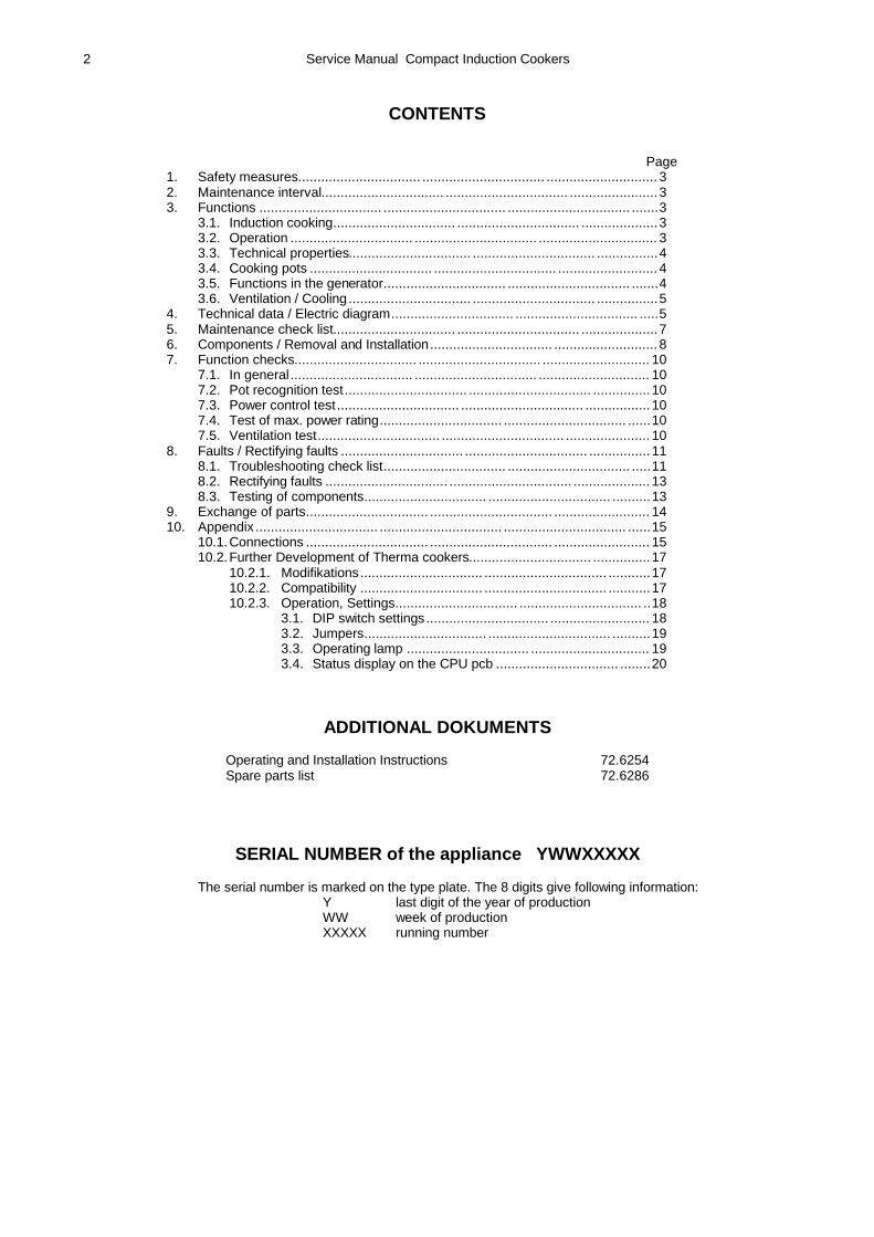
3.1. INDUCTION COOKINGWith induction cooking, the cooking pot is heated up withelectro-magnetic waves. The induction coil is fed with ahigh-frequency alternating current which generates apowerful magnetic field. If metallic objects are placed in
this area of the magnetic field, an eddy current is initiatedin them. This current penetrates the metallic objects, thatis, the bottom and wall of metal pots, and thus heats uptheir content.
Componentsa Mains connectionb Frequency changerc Operating paneld Parallel condensere Induction coilf Ferritic shieldg Glass ceramic plateh Magnetic field
3.2. OPERATIONThe required heating levels can be set in 9 steps byturning the control knob. The induction cooker'sperformance is depending of the position of the controlknob and of the size and material of the pan.The appliance is switched off when the control knob is inposition 0. When the control knob is switched on the greenlamp lights. The setting positions correspond to followingheating capacities:
Positionof knob 0 1 2 3 4 5 6 7 8 9
Capacity% off 10 15 20 25 30 50 65 85 100
4 Service Manual Compact Induction Cookers
3.3. TECHNICAL PROPERTIES- high performance and immediate readiness for operation- high efficiency- electric energy is directly transformed into heat in the pot
bottom- high energy saving- stepless power regulation by the operation of a rotary
regulator- pot recognition system- minimal loss of energy when on standby
3.4. COOKING POTSWith induction cooking it is very important to use suitablepots. The pot bottom is the element that closes themagnetic field generated by the induction coil. Thefollowing requirements must be met. They apply to potswith level bottoms as well as to WOK pans.The pots and pans must be made of a magnetic metal,such as iron, enamelled iron, carbon steel, cast iron,multilayered metal with a ferromagnetic layer on thebottom, iron-containing stainless steel, etc. Pots made ofcopper or aluminium must be equipped with a bottommade of steel or stainless steel with iron. Check themagnetic permeability with a permanent magnet. A pot issuitable for induction cooking when it has a bottom thatstrongly attracts a permanent magnet. We recommend theuse of cooking pots that were specially designed forinduction cooking. However, it is possible to use some ofthe traditional pots, too, such as the Lyon pan, pots andpans made of ferromagnetic stainless metals, enamelledpots, pots made of cast iron. You may also heat up certainmagnetic, non-conductive pot materials on the inductionrange. However, this is not recommended, as those potsdo not transmit the heat properly.Pans made of multi-layered metals with open aluminiumcore should not be used.The maximum power generated by the induction coildepends on the quality of the pot and the size of itsbottom. The larger the pot bottom, the more heat isgenerated in the pot and released to the food.
3.5. FUNCTIONS IN THE GENERATOR
Fan controlThe fan is controlled by a thermostat and does only switchon if the temperature in the heat sink reaches 55°C. Thefan switches off once the temperature in the heat sink hasreached the lower level of the thermostat. When theappliance is switched off the fan stops.
Induction coilThe connections of the coil must be wrenched andprotected by an isolating hose. Each coil has a built-intemperature sensor.
Power switchOn position "0" the power switch is turned off and theoutput signal has the resistance value 0. On positions 1 to9 the power switch is turned on and the output signal hasthe corresponding resistance value (max. 9 kΩ ).Setting the power ratingThe power rating is set with the potentiometer. The forceof the inductive power depends on the position of thepotentiometer and on the size and metal of the pot. Theinductive power can also be diminished by removing thepot from the center of the cooking zone. The power controlis sequential for the lower and progressive for the higherposition numbers.Sequential positionsWithin these positions there are power impulses emitted. It
takes about 1.4 s to complete a cycle. The duration of animpulse varies according to the set levels.Progressive positionsWithin these positions the power rating augments steadilywith increasing position numbers.
Pot recognition systemThe generator has an automatic pot recognition system. Acontrol impulse of the induction coil checks about every1.4 s whether there is a pot on the cooking zone and if thispot is suitable or not. If a suitable pot is placed on thecooking zone, the inductive heating goes on automatically.If the pot is removed, the inductive heating goes offautomatically. The inductive heating must only switch onwhen the pot placed on the cooking zone is of the requiredminimal size (approx. 12 cm). This prevents small,misplaced metallic objects from being heated up on thecooking zone.
Temperature controla) Induction coilThe temperature of the induction coil is controlled by atemperature sensor. If a coil is heated up to more than thetolerated maximum level, this generator will switch off andget blocked. After the coil has cooled down and resettingthe cooking zone is ready for operation again.b) Power moduleThe temperature of the power module is controlled by athermostat (safety thermostat). If the heat of the powermodule on the heat sink increases 55°C, the fan isswitched on. At temperatures over 70°C, the power will bereduced by 1/3. If the temperature still increases, thisgenerator will switch off. After the temperature aroundheat sink has dropped, the generator will switch onautomatically (no reset necessary).c) Temperature inside the applianceOn each control print there is a temperature sensor whichcontrols the temperature inside the appliance. If the heatexceeds the tolerated level on the control print, thegenerator will switch off. If the temperature on the controlprint drops, the same generator switches on automatically(no reset necessary).
Over current protectionIf non-ferromagnetic metallic objects (e.g. aluminium,copper, brass, chrome nickel steel, etc.) are placed on thecooking zone, the current in the induction coil canconsiderably increase. To protect the power module fromdestruction due to too fast a temperature rise within thismodule, there is a current control in the coil. If the currentsurpasses the tolerated level, the concerned generatorgets blocked. To release this blockage of the generator,switch off the concerned cooking zone (reset) for amoment. With the usual induction pots normally themaximum coil current will not be exceeded.
Voltage controlA supervision of excessive or low-tension voltage of themains is integrated in the power board. When the tensionlimits are reached the appliance is switched off.
Radio interference suppressionA mains filter for the radio interference suppression isintegrated in the power board.

Service Manual Compact Induction Cookers 5
3.6. VENTILATION / COOLING
GeneratorThe generator is force-cooled with a fan. The thermostatcontrol prevents the interior part of the appliance frombeing severely soiled. The fan operates at high powerlevels only during cooking. If small pots are used, or if thetemperature is set to a low level, the fan operates not orjust periodically. There is an air filter underneeth the
appliance.
Induction coilThe coil is cooled only naturally.
RecommendationDo not disconnect the plug of the appliance from themains socket while the fan is running.
4. TECHNICAL DATA
Type: VARIO INDUC VI VI 230 VI 400 VI 440Wattage kW 3,5 5 5Voltage 230V/1∼ N 400V/3∼ N 440V/3∼ (N)Current A 15.2 7.2 6.5Ceramic hob mm 340 x 340 340 x 340 340 x 340Appliance dimensions B/T/H mm 400 x 475 x 120 400 x 475 x 120 400 x 475 x 120Net weight kg 13 13 13
Type: VARIO WOK VW VW 230 VW 400 VW 440Wattage kW 3,5 5 5Voltage 230V/1∼ N 400V/3∼ N 440V/3∼ (N)Current A 15.2 7.2 6.5Ceramic bowl diameter mm 290 290 290Appliance dimensions B/T/H mm 400 x 475 x 180 400 x 475 x 180 400 x 475 x 180Net weight kg 13 13 13
For all types:Power factor cosϕ: >0.90; typical 0.95Leakage current 4 mA
Safety elements- 1 Protection switch per induction coil (temperature
sensor 180°C).- 1 Protection switch per power unit (power reduction of
1/3 at 70°C, cut off at 80°C).- 1 Protection switch per mains logic board (temperature
sensor 65°C).- 1 Overcurrent protection per power unit- 1 Electric fuse per control circuit
MiscellaneousMaximum tolerance of the mains: nominal voltage
+6/ -10%Supply frequency: 50 / 60 HzProtection class: IP X2
Minimal diameter of the pot bottom: about 12 cmMaximum ambient temperature
- storage room: -20.÷.+70°C- during operation: +5.÷.+42°C
Maximum humidity of air- storage room: 10.÷.90%- during operation: 30.÷.90%
Tests/certificates All electric appliances are tested by VDE. They fulfillfollowing standards and EC Directives. The appliances aremarked with the CE marking on the specification plate.EN 60335 SafetyEN 55014 Interference emissionEN 55104 Disturbance immunityLV Directive 73/23/EEC Low Voltage DirectiveEMV Directives 89/336/EEC Electro-magnetic
compatibility

6 Service Manual Compact Induction Cookers
Electric diagram (VARIO INDUC VI, VARIO WOK VW) 400V (230)
A1 Mains control / power unitA2 Logic boardB1 Temperature sensor of the coilH1 Control lamp greenL1 Induction coil
M1 FanS1 Power switchL1, L2, L3 PhasesN EarthK Connection cable

Service Manual Compact Induction Cookers 7
5. MAINTENANCE CHECK LIST
Check Fault ⇒ Remedy
Connections for protective conductors Check that all electric connections and contacts to terminals,coils, switches and junctions are tight. If contacts are loose ⇒ tighten contacts.
Measure the individual phase currents with a clamp-on ammeteron the power supply immediately before the connection terminalswith the appliance switched on full and compare the currents withthe ‘Technical data’.
Identify defective consumers (heating systems) by carefullymeasuring the individual currents. If major deviations arediscovered ⇒ replace.
Inspect internal wiring. If cables are faulty ⇒ replace cables.Check the cooking zones for continuous operation. Check powerconsumption with the largest possible pan filled with water.Check the generator and cooling block for internal contamination. If heavily soiled with grease and dust ⇒ clean with a brush or a
cloth and a spray cleaner intended for electronic componentsand blow out with compressed air.
Check the fan for operation and dirt. Note when the fan cuts in(should cut in after approx. 1-2 min. under full load). Fan must spinfreely and should turn when subjected to a current of air.
If the fan is dirty ⇒ clean with a brush or with compressed air.If the fan fails to spin freely after cleaning or the bearings arenoisy ⇒ replace the fan.
Check switch for easy movement and correct function. If the switch is hard to turn or makes a noise ⇒ replace.Check the the power switch steps. If the switch is found to be faulty, always replace the entire unit.Check the green operating lamp located on the control panel. Thelamp must be on at all switch settings from 1 to 10.
If the lens is damaged or the lamp fails to come on:⇒ replace the complete lamp.
Check the pan detection system by turning the switch to 9 andplacing a metal pan containing water onto the cooking zone.
If the heating fails to come on or fails to go off when the pan isremoved ⇒ replace the control print in the drawer.
Check the ceramic plate and wok bowl for any splits, cracks orwear and tear.
If the damage is likely to affect safety ⇒ replace the part.
Check the mecanical fixation of the induction coil and ferriteparts.
In case of changes ⇒ correct position and renew the fixation.
Check the seal between the ceramic plate / bowl and the cover. If damage is only slight ⇒ repair with silicone. If damage issevere ⇒ remove the plate / bowl and fit a new one.
MAINTENANCE
VentilationA proper function of the cooker can only be guaranteed, ifthe electronics can be kept at normal operatingtemperatures.- The air inlet and air outlet may not be obstructed- Air channels must be free of dirt- The heat sink lets the air flow through, no obstructions- The fan is mechanically well fixed- Air channeling panels are properly mounted- Filter is cleaned
Induction coilControl:- Mechanical fixation (screws fixed?)- Coil adhesive (fixation ok?)- Parts of ferrite (well fixed?)
In generalControl:- Protective ground connections- Screw connections- Cable insulation- Any kind of liquid spilled into the cooker'- Dirt inside the cooker

8 Service Manual Compact Induction Cookers
6. COMPONENTS / REMOVAL AND INSTALLATION
Casing (1)Removal: Remove the 6 screws (10) underneath theappliance. These security screws can only be handled witha special key (see ‘Spare parts list‘ 72.6286 / pos 10a). Theinterior of the appliance can now be accessed.Installation: Proceed as described under “Removal” but inthe reverse order.Ceramic hob (3)If the ceramic plate is damaged replace the entire cover(casing with ceramic plate built in) or only the ceramicplate.Procedure for changing the plate:Break up and remove the ceramic plate. Clean off allsilicone residues and inserts. Clean and degrease theframe parts. Bond the 2.6 mm-thick silicone inserts (4) tothe frame at a spacing of approx. 10 cm. Apply the siliconesealant (5) (Novasil S 76 black) to the frame from a tube.Insert the ceramic plate and press it down well. The coverand the ceramic plate should be flush. Apply siliconesealant to the joints. Smooth off the silicone using soapywater and rubber gloves. Remove any excess silicone.Allow the sealant to dry for 24 hours. Clean any sealantresidues off the cover and the ceramic plate with detergent,fine steel wool and paper.Wok pan (130)If the bowl is damaged replace the entire cover (casing withbowl and coil built in).Operating foil (2) exchangeRemoval:Operating foils (FO) and base plates (GR) are bonded tothe sheetmetal surfaces (cover plates) with self-adhesivecoatings. They are removed with a spatula, a screwdriveror a knife.Cleaning:The surfaces to which the foil is to be applied must beclean and dry, i.e. free from dust, grease, rust, paint, etc.Suitable for cleaning: toluol or 3M article S-152 stickremover.Procedure: shake the can thoroughly and spray evenly onthe surface to be cleaned. (Distance about 15 - 20 cm.)Rub over with a clean lint-free cloth. If surfaces are heavilysoiled, repeat the process.Sticking on the foil:Remove the protective backing, taking care not to touch theadhesive. After positioning, press down well. It is importantto apply firm, even pressure. The ideal workingtemperature is approximately 25°C. Temperatures below10°C should be avoided since the adhesive becomes toohard and instantaneous adhesion is reduced. Followingapplication, the foil has a working temperature range from -40° to + 120°C continuous temperature load and 180°Cshort-time temperature load.Filter (7)A filter drawer is located underneath the appliance whichcan be pulled out from the front side.INDUC coil (30)Removal: Unscrew the 4 screws (31) and disconnect theleads from the power- and logic boards.Installation: Proceed as described under “Removal” but inthe reverse order.

Service Manual Compact Induction Cookers 9
Switch (15)Removal: Pull the knob (40) off its spindle. Remove the twoscrews (30, 31). Extract the switch from the inside. Take offthe wiring connections.Installation: Proceed as described under “Removal” but inthe reverse order.Logic board (1)Removal: Disconnect the leads. Take off the plastic clips(14) and nuts respectively.Installation: Proceed as described under “Removal” but inthe reverse order.Power board (5)The power circuit board is constructed as a unit with theheat sink and may only be replaced as a complete unit.Removal: First remove the INDUC coil. Remove thedeflector (26) fitted to the fan (16). Remove the sheet (40)by unscrew the nuts (21). Disconnect the leads from thepower board.Take off the all nuts and screws. Pull theboard out.Installation: Proceed as described under “Removal” but inthe reverse order.Fan (16)Removal: Undo the screws (45) from underneath theappliance. Disconnect the leads.Installation: Proceed as described under “Removal” but inthe reverse order.Lamp (13)Removal: Disconnect the leads. Remove the nut (50) fromthe inside of the appliance. The lamp can be pulled out ofthe front panel.Installation: Proceed as described under “Removal” but inthe reverse order.Cable (45)If the exchange of the cable is necessary, the wires of thesupply (3P resp. P+N) must be wound around theringshaped core (50).

10 Service Manual Compact Induction Cookers
7. FUNCTION CHECKS
7.1. In general- After the maintenance of the appliance the serviceman
must carry out a function check.- To do that, pots should be used that are suitable and
that were specially designed for induction cooking.- To carry out a precise function test it is advisable to
measure the current of a phase with an ampere-meter.- The following two methods are used to check whether
the cooking zone is operating:- measuring the phase current- checking how much the pot has been heated up
- For the function check the pots must contain somewater.
- The level cooking zone and the WOK zone are testedwith the same tests.
7.2. Pot recognition testThis test shows whether the generator operates properlywith pots of a small diameter, and whether small metallicobjects are heated up on the cooking zone. To carry outthe test the following material is needed:induction pot with a bottom diameter of 12 cm or the- smallest pot available for the level cooking zone or- round steel disk with ∅ 12 and 7 cm
Step Activity Level Result1 Place pot or 12 cm disk on center
of cooking zone1 ... 9 Heating
on, lamplights
2 Move the pot away till its edge ison the center of the cooking zoneor place 7 cm disc in the center
1 ... 9 Heatingoff, lamp
off
7.3. Power control testThis test shows whether the power can be set throughout the whole range levels. For this test you need a pot with abottom diameter of > 12 cm for the level cooking zone and a WOK pan for the WOK zone.
Step Activity Level Result1 Place pot on cooking zone, wait till water boils 9 Heating on; water boils2 Turn knob slowly to lower levels 9 ... 1 Heating power and phase current decreases continuously;
water is not any more boiling
7.4. Test of maximum power ratingFor this test you need a pot with a bottom diameter of > 28 cm for the level cooking zone and a WOK pan for the WOKzone. Two different tests are possible.
Testing the cooking timeStep Activity Level Result
1 Place pot filled with several liters of water(~20°C) on cooking zone
9 Heating on
2 Measure the time needed for the water to boil 9 The heating up time must be:3.5 kW: approx. 150 sec./lit.5.0 kW: approx. 120 sec./lit.
Testing the currentStep Activity Level Result
1 Place pot with water on cooking zone 9 Heating on2 Measure the phase current 9 The phase current must be:
230/1N~V 3.5 kW: approx. 15.2 A400/3N~V 5.0 kW approx. 7.2 A
7.5. Ventilation testThis test is used to check the fan, the fan control, and thedegree of soiling. Before starting with the test, thegenerator must have cooled down. You need a pot with a
bottom diameter > 28 cm for the level cooking zone or aWOK pan for the Wok bowl.
Step Activity Level Result1 Place pot with water on cooking zone 9 Heating on2 Measure the time needed for the fan to switch
on9 Time = approx. 6 - 8 min.
3 Continue cooking for about 30 min. 9 The heating must not be interrupted. The fan may switch off inbetween times.
4 Switched off the appliance 0 The fan stops operating immediately. The fan is without timedelayed control.

Service Manual Compact Induction Cookers 11
8. FAULTS / RECTIFYING FAULTS
Attention: Before dismantling the appliance, the mainssupply must be switched off by pulling outthe plug.
When rectifying faults, the following must be observed:Repairs must be carried out by authorised servicemenonly. Always check the wiring before replacing a part ofthe appliance. Watch especially for the following faults:
- broken cables- crushed cables- damaged cable insulation
- poor solderingsNo repairs must be carried out on the print plate.After each repair it is necessary to carry out maintenancework according to chapter 5 and a function test accordingto chapter 7.
The following is a list of the main faults, their possiblecauses, and the corresponding remedial measures.
8.1. TROUBLESHOOTING CHECK LISTA suitable pan 1) with known characteristics should be used for the following tests.
Fault Possible Cause ActionCooker wrong connected Control connectionsShort circuit on the power board Control power board AP1
Preliminary fuse blowsduring switching ON
Short circuit in the wiring Control the wiringControl knob in OFF-position Turn control knob ON (power switch
ON)Main switch defective Control the voltage at clamps 5 and 6
(single phase supply) or 4, 5 and 6(three phase supply) on the power board
No mains supply Check preliminary fusesCheck mains connection
Supply voltage too low Control the supply voltageFuse(s) «logic supply» on the powerboard defective
Control fuses S1 and S2, replace (type1AT)
Pan too small (bottom diameter lessthan 12 cm)
Use a suitable pan
Pan is not placed in the center of theheating area (the cooker can't detectthe pan)
Move the pan to the center of theheating area
Unsuitable pan Choose a pan which is recommendedfor induction cooking 1)
Power board defective Control the power board AP2Logic board defective Control the logic board AL1Power switch defective Control power switch AO1
No heatingindicator lamp is OFF (dark)
Temperature sensor coil defective Control temperature sensor coil AT1No heating with small pans Pan detection wrong tuned Control the logic board AL2
Used pan is not ideal Use a pan which is recommended forinduction cooking 1). Compare resultswith known pan
Power switch defective Control power switch AO2Air-cooling system obstructed Verify, that air inlet and air outlet are not
obstructed with objectsAmbient temperature is too high (thecooling system is not able to keepthe cooker in normal operatingconditions 2)
Verify, that no hot air is sucked in by thefan. Reduce the ambient temperature.The temperature of the inlet air must notexceed 40°C.
One phase is missing (only withthree phase supply)
Check preliminary fuses
Power board defective Control the power board AP3
Poor heating, indicator lampis ON (lights)
Logic board defective Control the logic board AL3No reaction to control knobpositions
Power switch defective Control power switch AO3
Air inlet or outlet obstructed Remove objects from air inlet and airoutlet slots, clean the slots
Heating switches off and onwithin minutes, fan is active
Fan dirty Clean fan AF1

12 Service Manual Compact Induction Cookers
Fault Possible Cause ActionHeating switches off and onwithin minutes, fan is neveractive
Fan defectivefan control defective
Control fan AF2
After a longer permanentoperating time, the heatingswitches off and on withinminutes
Coil overheated, cooking area toohotempty panpan with overheated oil
Switch cooker off, remove pan and waituntil the cooking area has cooled off.
Small metallic objects (e.g.spoon) are heated up withinthe cooking area
Pan detection wrong tuned Control logic board AL4
1) To verify, if the pan is suitable, use a permanentmagnet and find out if it slightly sticks on the bottomof the pan. If not, your pan is not suitable for inductioncooking.
2) The cooling-system (fan) starts to operate when theheat sink temperature exceeds 55ºC. At heat sinktemperatures higher than 70ºC, the controllerautomatically reduces the power to keep the powerunit in normal operating conditions. The cooker runs ina non continuous mode which can be heard.

Service Manual Compact Induction Cookers 13
8.2. RECTIFICATIONDetailed description of the actions to take (according to «Troubleshooting check list»)
ActionAP1 Unplug the cooker from the mains supply. Check with an Ohmmeter for short circuit. Do the check with the
power switch in ON- and OFF-position. Locate the short circuit. If it is on the power board, replace the powerunit. Check the power switch
AP2 control the supply +24VDCST1/1: +24 VDC, ST1/4: GND (on power board and on logic board). If wrong, replace power unitcontrol the signals 'enable' (ST1/2) and 'low' (ST1/3) a) . If wrong, replace logic board. Test components (see«Component test»)
AP3 control the signals 'low' (ST1/3) and 'high0' (ST1/5) a) . If wrong, replace logic board, else test components onthe power unit (see «Component test»)
AL1 control the signals 'enable' (ST1/2) and 'low' (ST1/3) a) . If wrong, replace logic boardAL2 replace logic boardAL3 control the signals 'low' (ST1/3) and 'high0' (ST1/5) a) . If wrong, replace logic board, else replace power unit
(see also AP3)AL4 see AL2AO1 Unplug the cooker from the mains supply. Disconnect ST4 on the logic board. control the resistance (ST4/1 -
ST4/2) with an Ohmmeter:control knob position R (kOhm)
0 0 ± 5%4 4 ± 5%9 9 ± 5%
If wrong, replace the complete power switch.AO2 see AO1AO3 see AO1AT1 Unplug the cooker from the mains supply. Disconnect ST7 on the logic board. control the resistance (ST7/1 -
ST7/2) with an Ohmmeter:temp. Ceran plate R (Ohm)25ºC / 80ºF 980 ... 1000100ºC / 210ºF 1240 ... 1280150ºC / 300ºF 1410 ... 1450200ºC / 390ºF 1570 ... 1610if out of range, replace the coil including temperature sensor
AF1 disconnect and dismount the fan, clean itAF2 connect the signal 'venti0' (ST1/10) with GND (ST1/4): the fan must run. If no, fan defective, replace it,
otherwise logic board defective, replace it.ST1/1 = plug 1, connection 1 on logic boardGND = groundK016/K018 = designation of power and logic boardsa) see «Signals connector ST1»
8.3. COMPONENT TEST
Power unitControl of the functioning of the transistormodule and the rectifier.
Rectifier (S = view solder side of power board)Diode forward voltage UF = approx. 0.5V: if all forward voltagesare about 0.5 V, the rectifier is functioning.A short circuit between '+' and '-' is a hint, that thetransistormodule is defective.
Transistormodule (S = view solder side of power board)Diode forward voltage UF = approx. 0.4V: if all forward voltagesare about 0.4 V, the transistormodule is functioning.A short circuit between C2-E2, C1-E1 and C1-E2 says that thetransistormodule is defective.If the rectifier and/or the transistormodule seems to bedefective, separate the power board K016 from the heat sinkand test the rectifier and transistormodule without anyconnections.

14 Service Manual Compact Induction Cookers
RectifierThe rectifier is disconnected from the power board, stillmounted on the heat sink. How to disconnect, see«Replace power board».Diode forward voltage UF = approx. 0.5V: if all forwardvoltages are about 0.5 V, the rectifier is functioning.Short circuit across individual diodes: Rectifier is defective
Transistor moduleThe transistor module is disconnected from the powerboard, still mounted on the heat sink. How to disconnect,see «Replace power board».Diode forward voltage UF = approx. 0.4V: if all forwardvoltages are about 0.4 V, the transistor module isfunctioning.A short circuit between C2-E2, C1-E1 and C1-E2 says thatthe transistor module isdefective. If the module is defective, check the diodes D7,D8, D9, and D10 against short circuit. Replace the powerboard, if you detect any short circuit.
9. EXCHANGE OF PARTS
Power board K016(single phase, three phase)Removal- disconnect all plug connections on the power board: ST1- disconnect all clamp connections on the power board:
- single phase: L1, N, PE, 1, 2, 3, 4, 7, 8- three phase: L1, L2, L3, PE, 1, 2, 3, 4, 5, 6, 7, 8
- disconnect ST5 on logic board K018- loose the soldered connections J16, J17, J18, J19 with
the soldering iron- loose the bolt M4 and the screw M4 in the corners of the
board- loose the connections to the transistor module, 3 screws
M5x12- loose the connections to the rectifier, 5 screws M4x16
(three phase) or 4 screws M4x16 (single phase). Watchfor the spacers and washers: screw head - springwasher - spring washer - washer - spacer (place the twospring washers against one another).
- remove the power boardInstallation- place the board onto the bolts. Watch for the
connections J16, J17, J18, J19: The four wires from thetransistor module have to pass through the holes in thecircuit board
- apply the screws to fix the rectifier, 5 screws M4x16(three phase) or 4 screws M4x16 (single phase). Watchfor the spacers and washers: screw head - springwasher - spring washer - washer - spacer (place the twospring washers against one another)
- do not yet fix the screws- apply the screws to fix the transistor module, 3 screws
M5x12. Don't yet fix the screws- fix the rectifier screws- fix the transistor module screws. Fix them well, but not
too strong- fix the bolt M4 and the screw M4 in the corners of the
board- solder the connections J16, J17, J18, J19 with the solder
plating- connect all clamp connections on the power board:
- single phase: L1, N, PE, 1, 2, 4, 5, 7, 8- three phase: L1, L2, L3, PE, 1, 2, 3, 4, 5, 6, 7, 8
- connect all plug connections on the power board: ST1- connect ST5 on logic board K018- connect the coil to A1 and A2 (screws)
Logic boardRemoval- disconnect all plug connections on the logic board: ST1,
ST4, ST5, ST6, ST7, ST8- loose the nut M3 and the 3 plastic bolts- remove the logic board
Installation: Proceed as described under “Removal” but inthe reverse order.
Transistor ModuleFirst dismantle the power board K016- loose the socket head cap screws- remove the module from the heat sink- clean the heat sink surface: remove the heat conduction
paste, for example with methylated spirit- apply a coat of heat conducting paste to the new
transistor module. Make sure, that the whole bottom sideof the module is well covered
- fix the module with the socket head cap screws on theheat sink.
- fit the power board K016
RecitifierFirst dismantle the power board K016- loose the screws- remove the rectifier from the heat sink- clean the heat sink surface: remove the heat conduction
paste, for example with methylated spirit- apply a coat of heat conducting paste to the new
rectifier. Make sure, that the whole bottom side of themodule is well covered
- fix the rectifier with the screws on the heat sink- fit the power board K016
Fan- remove cables from terminals K7/K8- remove 4 screws from the bottom sheet- remove the fanInstallation: Proceed as described under “Removal” but in
the reverse order.
Temperature sensor heat sinkThe sensor is mounted in the cable terminal which is fixedat the transistor module. Just replace the whole unit (cableterminal with sensor, cable and connector).First dismantle the power board K016- loose the socket head cap screw on the transistor
module- remove the whole unit (cable terminal with sensor, cable
and connector)- remove the heat conduction paste, for example with
methylated spirit- apply a coat of heat conducting paste to the new cable
terminal- fix the cable terminal with the socket head cap screw on
the transistor module.- fit the power board K016

Service Manual Compact Induction Cookers 15
10. APPENDIX
10.1. CONNECTIONS
Components power board K016, 1 phase
clamp signal/function clamp signal/function connector signal/functionL1, N, PE mains 230VAC 1, 2 230VAC to circuit
breakerJ14, J15 coil current
7, 8 supply fan, 230VAC 3, 4 230VAC from circuitbreaker
ST1 signals to/from K018
Components power board K016, 3 phase
clamp signal/function clamp signal/function connector signal/functionL1, L2, L3,
PEmains 400VAC 1, 2, 3 400VAC to circuit
breakerJ14, J15 coil current
7, 8 supply fan, 230VAC(via relay)
4, 5, 6 400VAC from circuitbreaker
ST1 signals to/from K018
Connection to/from powerboard K016
L1 L2 L3 N PE5
Mainswitch
1 2 3 4 6
FAN
7 vi8
brvi
910
vibr
10 sz
8 gr9 ws
cable to c018
4567
21
3 3 or
5 gn6 bl
4 gb
1 br2 rt

16 Service Manual Compact Induction Cookers
Signals connector ST1
ST1 on power board K016 and ST1 on logic board K018 are directly connected (pin 1 to pin 1, pin 2 to pin 2 etc.). Thusthe signals are identical.
pin signal name short description1 +24 VDC supply +24V for logic board2 enable control transistormodules:
0V 5V __|¯|____...................__|¯|____ à ß 2us à ß 2us ß 20 ms à
3 low control transistormodules:logic-signal (High speed CMOS), frequency about 20 kHz
4 GND GND (logic)5 high0 control transistormodules 0:
logic-signal (High speed CMOS), frequency about 20 kHz6 high1 not used7 high2 not used8 high3 not used9 iph signal, proportional to phase current, range -5V to +5V10 venti0 activates the relay to start the cooling fan.
active ‚low‘, max. current 20mA
Connections to logic board C018
Service Manual Compact Induction Cookers 17
10.2. FURTHER DEVELOPMENT OF THERMA COMPACT INDUCTION COOKERS
10.2.1. MODIFICATIONS
Cycle timeThe cycle time for power control, overcurrent and pan sensor has been substantially reduced.The power unit is thus better protected and operation is more stable.
Trim potentiometer on the power unitAny tolerances on the power unit and the coil can be equalized.• Coil power is adjusted with a trimmer. (Nominal value ILC)• Maximum power is adjusted with a trimmer. (Nominal value IPH)
Trim potentiometer on the CPU pcb3 parameters can be adjusted on the CPU pcb.Each relevant trim potentiometer can be activated with a jumper.If the jumper is set, the relevant parameter is adjusted with the trim potentiometer. The value set can be read off via thestatus display (q.v. “DIP switch settings, Display mode).If the jumper is not set, the parameter is set to the standard value. The appliance can be safely used with the standardvalues.The following parameters can be adjusted:• Basic frequency 1)• Pan sensor• Overcurrent 1)
1) The parameter setting of basic frequency and overcurrent is optional. In addition, it may only be carried out by trainedpersonnel using special equipment.
Power limiterPower is limited to 105% of the rated power.This prevents the connected load from being exceeded.
Operating lampThe green lamp (previously only “Operating lamp”) displays the different operating states such as: searching, powerreduction and error messages with flashing code for all possible errors.
Status display on the CPU pcbThe 8 LEDs on the CPU pcb have a display function. A DIP switch is used to select the desired display mode. Displaymodes:• Normal display with display of errors• Actual value display of all sensors and currents
Same CPU pcb for a large number of appliancesThe same CPU pcb can be used for various appliances.The type of appliance concerned is set with a DIP switch.If the trim potentiometers on the CPU pcb are activated, they must be set or deactivated by removing the jumpers.
10.2.2. COMPATIBILITY
Power print1-phase appliances: C031a...3-phase appliances: C016c...The power pcb is not interchangeable with previous versions.
CPU pcbc018d...The CPU pcb is not interchangeable with previous versions.
Induction coilThe previous coil can no longer be used.

18 Service Manual Compact Induction Cookers
10.2.3. OPERATION, SETTINGS
3.1. DIP switch settingsThe DIP switch on the CPU pcb is used to select the appliance and the display mode.
SW1 - SW4: Display modeThese switches are used to set what is shown on the status display (LED1 - LED8 on the CPU pcb). (Please refer to:“Status display on the CPU pcb”)NB: The external operating lamp is coupled to LED1. For normal cooking operations, the display mode should always beset at the operating display (mode 0).
SW-4 SW-3 SW-2 SW-1 Mode Display-- -- -- -- 0 Operating display (normal operation)-- -- -- on 1 Temperature, external, in [°C]-- -- on -- 2 Temperature, cooking zone, in [bit] 1)-- -- on on 3 Temperature, cooling sheet, in [bit] 1)-- on -- -- 4 Temperature, interior, in [bit] 1)-- on -- on 5 Value of the rotary power knob in [bit] 1)-- on on -- 6 Trim potentiometer pot1 setting in [bit]-- on on on 7 Trim potentiometer pot2 setting in [bit]on -- -- -- 8 Trim potentiometer pot3 setting in [bit]on -- -- on 9 Coil current in [0.1A]on -- on -- 10 Primary current in [bit]on -- on on 11 Nominal value of temperature, external, in [°C]on on -- -- 12on on -- on 13on on on -- 14on on on on 15 Type of appliance 2)
1) The [bit] values can be converted using tables into [°C] values.2) The type of appliance is set using DIP switches SW5 - SW8. As this setting is the most important of all, it can be
checked here.
SW5 - SW8: Type of appliance
SW-8 SW-7 SW-6 SW-5 Nr. Type of appliance-- -- -- -- 0 IGL1AC230/3.5 – Vario Induc-- -- -- on 1 IGL3AC400/5.0 – Vario Induc-- -- on -- 2 IGL1AC230/3.5 – Vario Wok-- -- on on 3 IGL3AC400/5.0 – Vario Wok-- on -- -- 4-- on -- on 5-- on on -- 6-- on on on 7on -- -- -- 8on -- -- on 9on -- on -- 10on -- on on 11on on -- -- 12on on -- on 13on on on -- 14on on on on 15
Additional types of appliances are also being implemented.

Service Manual Compact Induction Cookers 19
3.2. Jumpers9 jumpers are available on the CPU pcb.The normal status of a jumper is off.off = jumper not seton = jumper set
JP-1 = On: trim potentiometer 3 (POT3) is active. Overcurrent can be adjusted with POT3. Turn CW = worse pans areaccepted. 1)
JP-2 = On: trim potentiometer 2 (POT2) is active. The pan sensor can be adjusted with POT2. Turn CW = smaller pansare not recognized.
JP-3 = On: trim potentiometer 1 (POT1) is active. The basic frequency can be adjusted with POT1. Turn CW = basicfrequency is increased. 1)
JP-4 = On: primary current measurement for 60Hz mains voltage.JP-4 = Off: primary current measurement for 50Hz mains voltage.JP-5 = On: switch off pan sensor. 1)JP-6 = On: switch off current control. 1)
JP-7 = On: switch off power limiter. 1)JP-8 = On: switch off overcurrent and undercurrent monitoring. 1)
JP-9 = Off: operation via rotary switchJP-9 = On: operation via 9K rotary switch
1) These functions may only be activated by trained personnel and only for test purposes. They can damage theappliance if incorrectly implemented.
3.3. Operating lamp (external green lamp)NB: The operating lamp is coupled to the CPU pcb with LED 1 on the status display. The operating lamp will only be
meaningful when the display mode is set to “operating display” (q.v. “DIP switch settings”)The following statuses are displayed:
Appliance is offLamp is OFF.The appliance has no power or the rotary power knob is at 0.
Normal operationLamp is permanently ON.Rotary power knob is at 1-10, pan is on the cooking zone
Search operationLamp flashes every second. (50ms ON, 950ms OFF)Rotary power knob is at 1-10, there is no pan on the cooking zone
Power reductionLamp flashes every second (Lamp is ON in step with power output)Rotary power knob is at 1-10, pan is on the cooking zone.The appliance is only operating in clock mode with reduced power.
Error messageLamp ON for 0.6 secs. A code sequence will then flash (1 flash means: 300ms OFF, then 200ms ON).Rotary power knob is at 1-10The error code can be read off the error messages table (q.v. “Status display”).

20 Service Manual Compact Induction Cookers
3.4. Status display on the CPU pcbThe 8 LEDs on the CPU pcb are used as a status display. The display mode is set using the DIP switches (q.v. “DIPswitch settings”)The display is binary.
Display modes 1 - 15A value from 0 - 255 is shown in binary form. LED1 - LED8 have the following values:
LED Bit Value Colour CommentLED1 0 1 green LSBLED2 1 2 greenLED3 2 4 greenLED4 3 8 greenLED5 4 16 redLED6 5 32 redLED7 6 64 redLED8 7 128 red MSB
Example: LED1, LED3, LED6, LED8 lights = 1 + 4 +32 + 128 = 165
Display mode 0 (normal operation)The 4 red LEDs (LEDs 5 - 8) are used to display errors in binary form. The lower number always has priority if severalerrors are displayed simultaneously.
ERROR MESSAGES
LED 8 LED7 LED6 LED5 Code Meaning-- -- -- -- -- No errors, normal operation-- -- -- on 01 No coil current, hardware overcurrent-- -- on -- 02 High coil current, software overcurrent-- -- on on 03 Temperature of cooling sheet-- on -- -- 04 Temperature of cooking zone 1)-- on -- on 05 Rotary power knob, power cable breakage-- on on -- 06 Internal temperature-- on on on 07 Cooking zone sensor short circuit 2)on -- -- -- 08 External temperature sensor unplugged or faulty 1)on -- -- on 09 Error in operation with external temperature sensor 1)on -- on -- 10on -- on on 11on on -- -- 12 Power reduction, cooling sheet temperature 3)on on -- on 13 Power reduction, cooking zone temperature 3)on on on 14 Power reduction due to bad pan 3)on on on on 15
1) The appliance will not switch on again before the error has been acknowledged (turn the power potentiometer to the0 position).
2) The appliance will continue to function normally but the cooking zone temperature is no longer being monitored.3) The appliance continues to work at reduced power in clock mode. The error code is not sent serially to the operating
lamp. The operating lamp flashes in step with the power output.