service manual - air-con...
TRANSCRIPT

Service Manual
A16EW4H4R09 A16EW4H4R12 A16EW4H4R18
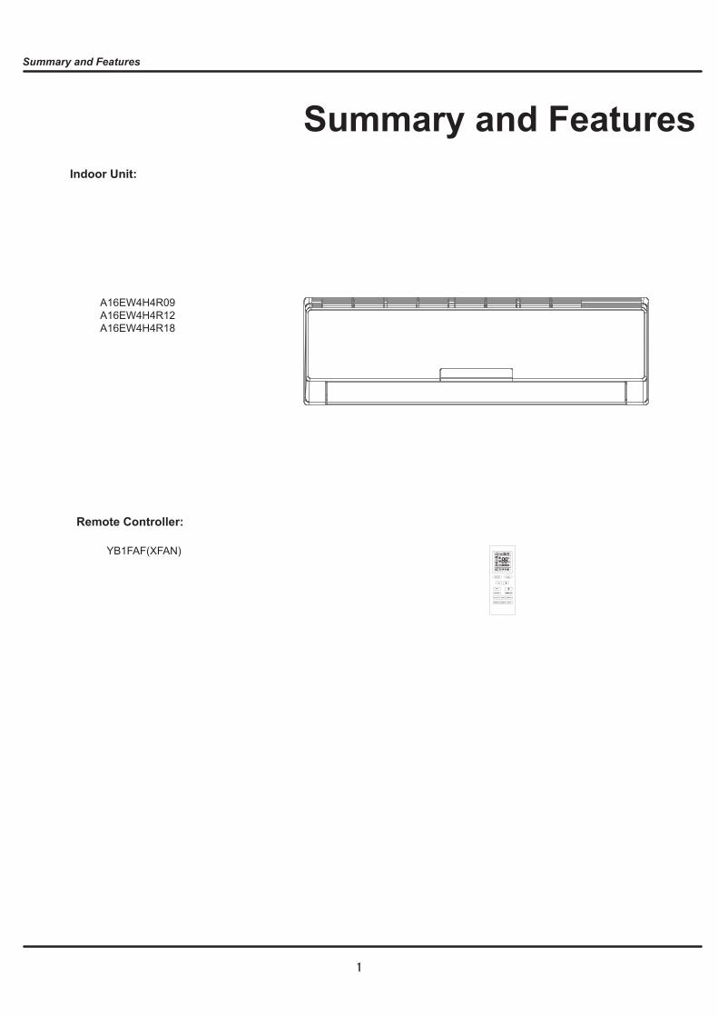
A16EW4H4R09 A16EW4H4R12 A16EW4H4R18
ON OFF/ MODE
FAN
CLOCK TIMER ON
X-FAN TEMP TIMER OFF
TURBO SLEEP LIGHT
1
2
A16EW4H4R09 A16EW4H4R18A16EW4H4R12
3
0
10
Noi
ce/d
B(A
)
20
30
40
50
60
Low Middle Super HighHigh
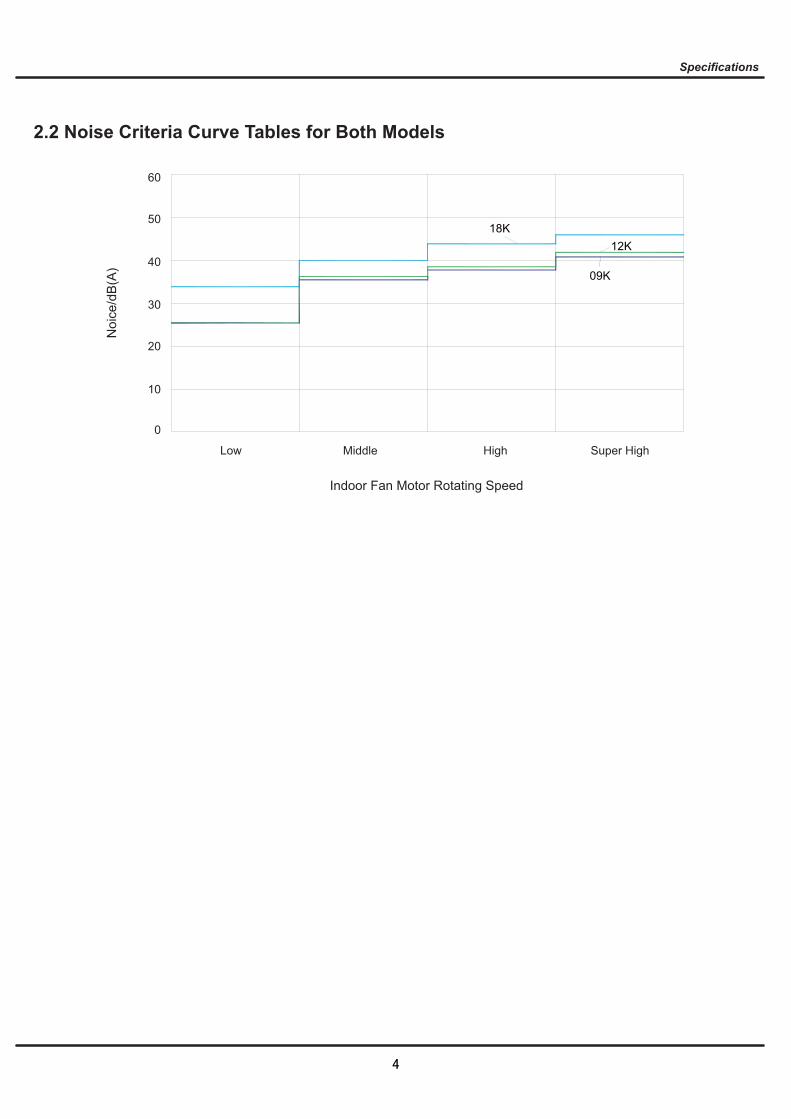
Indoor Fan Motor Rotating Speed
18K12K
09K
4
5
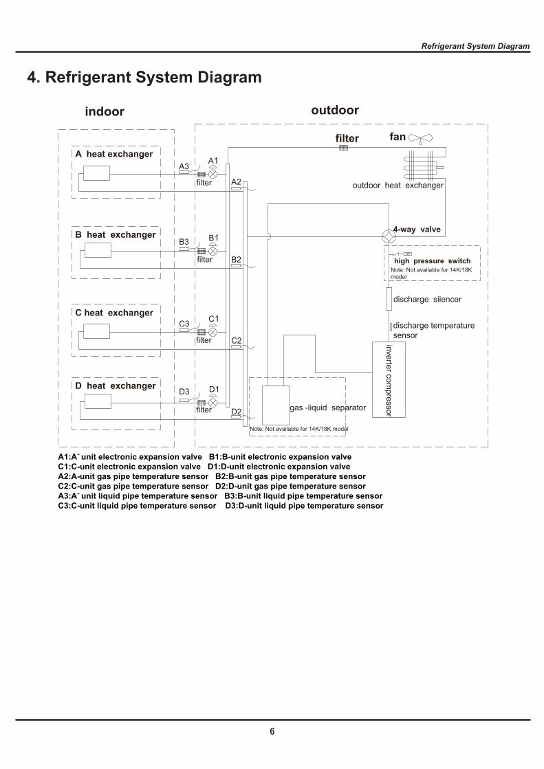
outdoorindoor
D1
C1
B1
A1
filterA heat exchanger
gas -liquid separator
inverter compressor
discharge silencer
discharge temperature sensor
SP
4-way valve
outdoor heat exchanger
fan
high pressure switch
B heat exchanger
C heat exchanger
D heat exchanger
filter
filter
filter
filter
Note: Not available for 14K/18K model
C2
C3
D3
D2
B3
B2
A2
A3
A1:A-unit electronic expansion valve B1:B-unit electronic expansion valveC1:C-unit electronic expansion valve D1:D-unit electronic expansion valveA2:A-unit gas pipe temperature sensor B2:B-unit gas pipe temperature sensorC2:C-unit gas pipe temperature sensor D2:D-unit gas pipe temperature sensorA3:A-unit liquid pipe temperature sensor B3:B-unit liquid pipe temperature sensorC3:C-unit liquid pipe temperature sensor D3:D-unit liquid pipe temperature sensor
Note: Not available for 14K/18K model
6

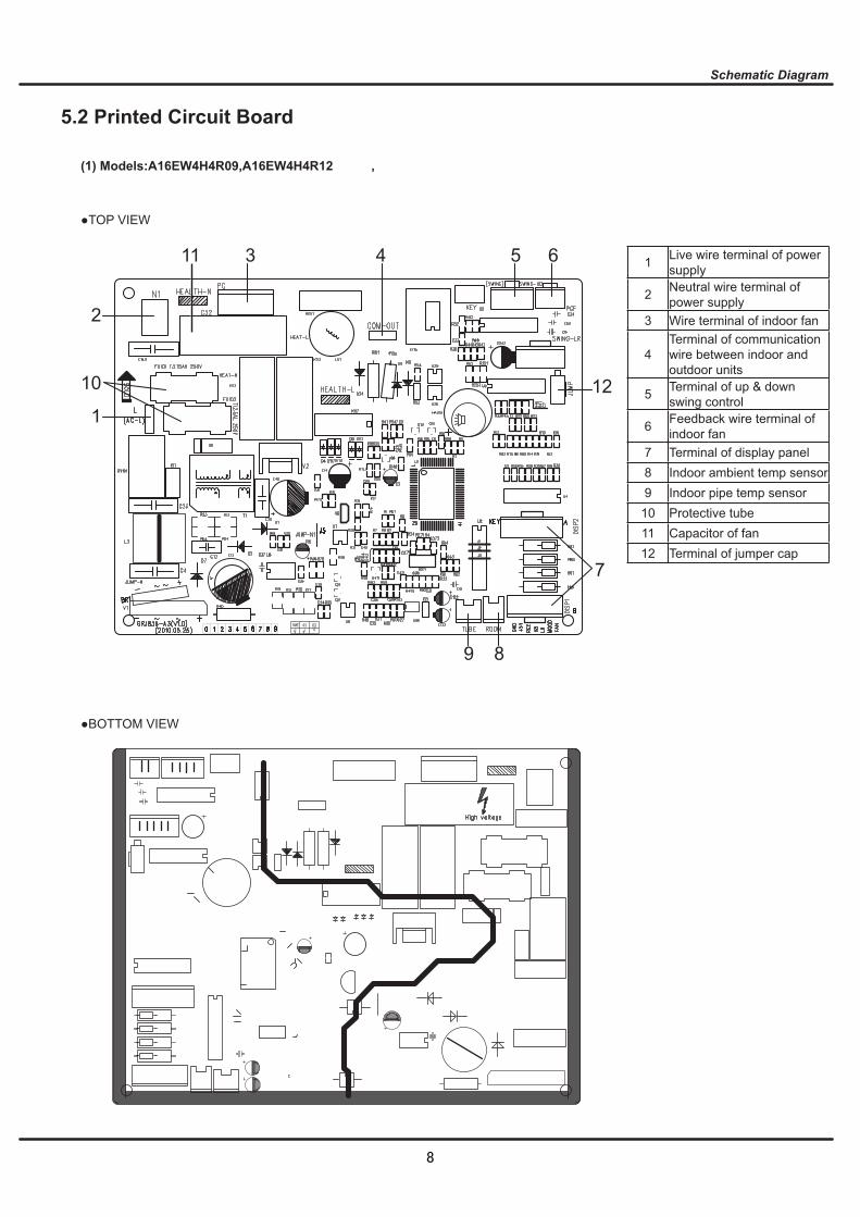
AP1
RECEIVER ANDDISPLAY BOARD
BU RD
HEALTH-N HEALTH-L
GENERATORCOOL PLASMA
EVAPORATORG
ELECTRIC BOX
YEGN(GN)
0
TEMP. SENSORTEMP. SENSOR
AC-L
BK
G
ROOMTUBE
M2
SWING-UD
ROOM
RT2
AP2BN
PG
YEGN(GN)
0 M1
BU
FANTUBE
RT1
SWINGMOTOR
COM-OUT
N
PGF
MOTOR
CAP
JUMP
DISP2DISP1
23
N(1)
23
N(1)
TERMINALBLOCKTERMINAL
BLOCK
OUTD
OOR
UNIT
XT
XT
L
L
NOTE:The parts with broken line is applicableto the models with COOL PLASMA GENERATOR
TEMP. SENSORTEMP. SENSORROOM
FANTUBE
MOTOR
RT2 RT1
ROOMTUBE PG PGF
AC-L
BK
BN
BU
COM-OUT
N
23
N(1)
23
N(1)
TERMINALBLOCKTERMINAL
BLOCK
OUTD
OOR
UNIT
XT
XT
L
L
L
YEGN(GN)
YEGN(GN)
EVAPORATORG
ELECTRIC BOXG
BU RD
HEALTH-N HEALTH-L
GENERATORCOOL PLASMARECEIVER AND
DISPLAY BOARD
SWING-UD
SWINGMOTOR
DISP2DISP1
AP1
AP2CAPJUMP
M2
M1
NOTE:The parts with broken line is applicableto the models with COOL PLASMA GENERATOR
7
1
2
3 411 5 6
12
7
89
10
A16EW4H4R09,A16EW4H4R12
8
A16EW4H4R18
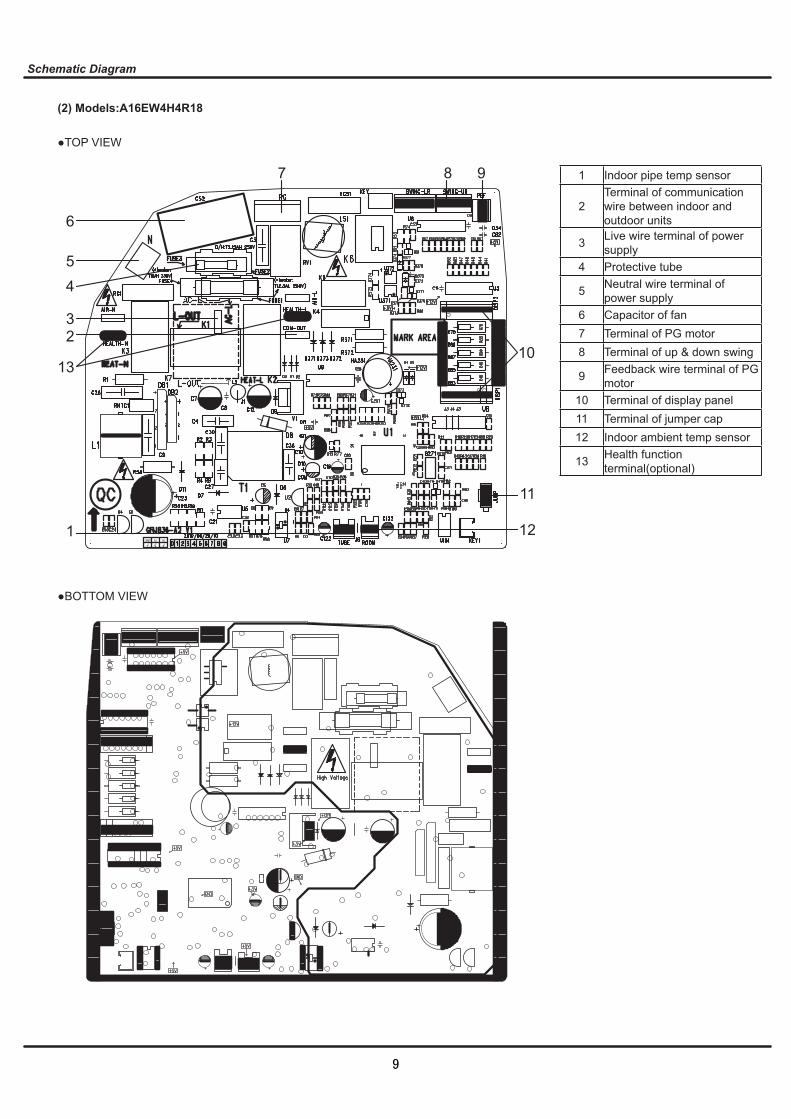
1
2
13
3
45
6
7 8 9
10
11
12
9
1
7
8
4
3
5
6
11
13
12
16
17
18
10
14
9
15
2
2
8
9
10
34
11
12
7
6
13 14
5
1
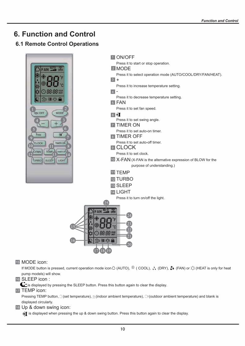
ON/OFFPress it to start or stop operation.MODEPress it to select operation mode (AUTO/COOL/DRY/FAN/HEAT).+Press it to increase temperature setting.-Press it to decrease temperature setting.FANPress it to set fan speed.
Press it to set swing angle.TIMER ONPress it to set auto-on timer.TIMER OFFPress it to set auto-off timer.CLOCKPress it to set clock.
X-FAN
TEMPTURBOSLEEPLIGHTPress it to turn on/off the light.
17
15
18 19
1620
21
23
24
22
25
MODE icon:If MODE button is pressed, current operation mode icon (AUTO), ( COOL), (DRY), (FAN) or (HEAT is only for heat pump models) will show.SLEEP icon : is displayed by pressing the SLEEP button. Press this button again to clear the display.TEMP icon:Pressing TEMP button, (set temperature), (indoor ambient temperature), (outdoor ambient temperature) and blank is displayed circularly.Up & down swing icon: is displayed when pressing the up & down swing button. Press this button again to clear the display.
(X-FAN is the alternative expression of BLOW for the purpose of understanding.)
10

20
21
22
23
24
25
1
2
3
4
5
6
19 LIGHT icon: is displayed by pressing the LIGHT button.Press LIGHT button again to clear the display.LOCK icon: is displayed by pressing "+" and “-” buttons simultaneously.Press them again to clear the display.SET TIME display:After pressing TIMER button, ON or OFF will blink.This area will show the set time.TURBO icon: is displayed when pressing theTURBO button.Press this button again to clear the display.DIGITAL display:This area will show the set temperature. In SAVE mode,"SE" will be displayed. During defrosting operation, “H1” will be displayed.X-FAN icon: is displayed when pressing the X-FAN button. Press this button again to clear the display.FAN SPEED display:Press FAN button to select the desired fan speed setting(AUTO Low-Med-High).Your selection will be displayed in the LCD windows,except the AUTO fan speed.
ON/OFF:Press this button to turn on the unit. Press this button again to turn off the unit.MODE:Each time you press this button,a mode is selected in a sequence that goes from AUTO, COOL,DRY, FAN, and HEAT *, as the following:
*Note: Only for models with heating function.After energization, AUTO mode is defaulted. In AUTO mode, the set temperature will not be displayed on the LCD, and the unit will automatically select the suitable operation mode in accordance with the room temperature to make indoor room comfortable.+ :Press this button to increase set temperature. Hold it down for above 2 seconds to rapidly increase set temperature. In AUTO mode, set temperature is not adjustable.-:Press this button to decrease set temperature. Hold it down for above . 2 seconds to rapidly decrease set temperature. In AUTO mode, set temperature is not adjustable.FAN :This button is used for setting fan speed in the sequence that goes from AUTO, , , to then back to Auto.
Press this button to set up & down swing angle, which circularly changes as below:
This remote controller is universal. If any command , or is sent out, the unit will carry out the command as indicates the guide louver swings as:
AUTO
COOL DRY FAN HEAT*AUTO
Low speed Medium speed High speed
OFF
Remote Controller Description
11
8
9
10
11
12
13
14
15
16
7 TIMER ON:Press this button to initiate the auto-ON timer. To cancel the auto-timer program, simply press this button again. After pressing this button, disappears and "ON" blinks . 0 0:00 is displayed for ON time setting. Within 5 seconds, press + or - button to adjust the time value. Every press of either button changes the time setting by 1 minute. Holding down either button rapidly changes the time setting by 1 minute and then 10 minutes. Within 5 seconds after setting, press TIMER ON button to confirm.TIMER OFF:Press this button to initiate the auto-off timer. To cancel the auto-timer program, simply press the button again.TIMER OFF setting is the same as TIMER ON.CLOCK :Pressing CLOCK button, blinks. Within 5 seconds, pressing + or - button adjusts the present time. Holding down either button above 2 seconds increases or decreases the time by 1 minute every 0.5 second and then by 10 minutes every 0.5 second. During blinking after setting, press CLOCK button again to confirm the setting, and then will be constantly displayed.X-FAN:Pressing X -FAN button in COOL or DRY mode,the icon is displayed and the indoor fan will continue operation for 10 minutes in order to dry the indoor unit even though you have turned off the unit.After energization, X-FAN OFF is defaulted. X-FAN is not available in AUTO, FAN or HEAT mode.TEMP:Press this button, could select displaying the indoor setting temperature or indoor ambient temperature.When the indoor unit firstly power on it will display the setting temperature, if the temperature's displaying status is changed from other status to" ",displays the ambient temperature, 5s later or within 5s, it receives other remote control signal that will return to display the setting tempera-ture. if the users haven't set up the temperature displaying status,that will display the setting temperature.TURBO:Press this button to activate / deactivate the Turbo function which enables the unit to reach the preset temperature in the shortest time. In COOL mode, the unit will blow strong cooling air at super high fan speed. In HEAT mode, the unit will blow strong heating airat super high fan speed. SLEEP:Press this button to go into the SLEEP operation mode. Press it again to cancel this function. This function is available in COOL, HEAT (Only for models with heating function) or DRY mode to maintain the most comfortable temperature for you.LIGHT:Press LIGHT button to turn on the display's light and press this button again to turn off the display's light. If the light is turned on , is displayed. If the light is tunrned off, disappears.Combination of "+" and "-" buttons: About lockPress "+ " and "-" buttons simultaneously to lock or unlock the keypad. If the remote controller is locked, is displayed. In this case, pressing any button, blinks three times.Combination of "MODE" and "-" buttons:About switch between Fahrenheit and Centigrade At unit OFF, press "MODE" and "- " buttons simultaneously to switch between ℃ and ℉.
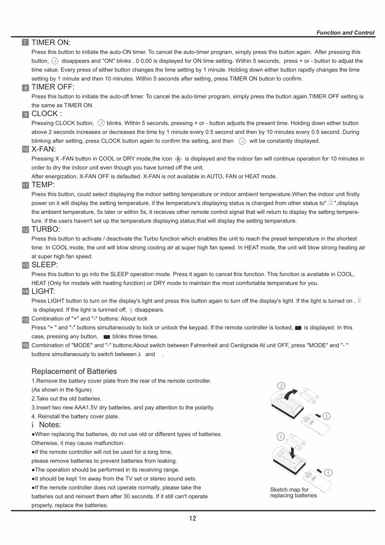
Replacement of Batteries1.Remove the battery cover plate from the rear of the remote controller.(As shown in the figure)2.Take out the old batteries.3.Insert two new AAA1.5V dry batteries, and pay attention to the polarity.4. Reinstall the battery cover plate.★Notes:●When replacing the batteries, do not use old or different types of batteries. Otherwise, it may cause malfunction.●If the remote controller will not be used for a long time, please remove batteries to prevent batteries from leaking.●The operation should be performed in its receiving range.●It should be kept 1m away from the TV set or stereo sound sets.●If the remote controller does not operate normally, please take thebatteries out and reinsert them after 30 seconds. If it still can't operate properly, replace the batteries.
Sketch map forreplacing batteries
12
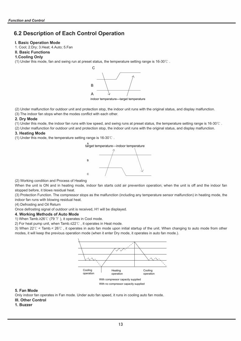
Coolingoperation
Heatingoperation
Coolingoperation
With compressor capacity suppliedWith no compressor capacity supplied
A
B
C
indoor temperature---target temperature
A
B
C
target temperature---indoor temperature
13
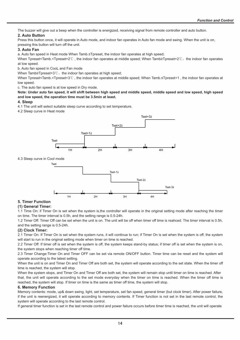
Tset
Tset+1℃
Tset+2℃
Tset+3℃
1H 2H 3H 4H
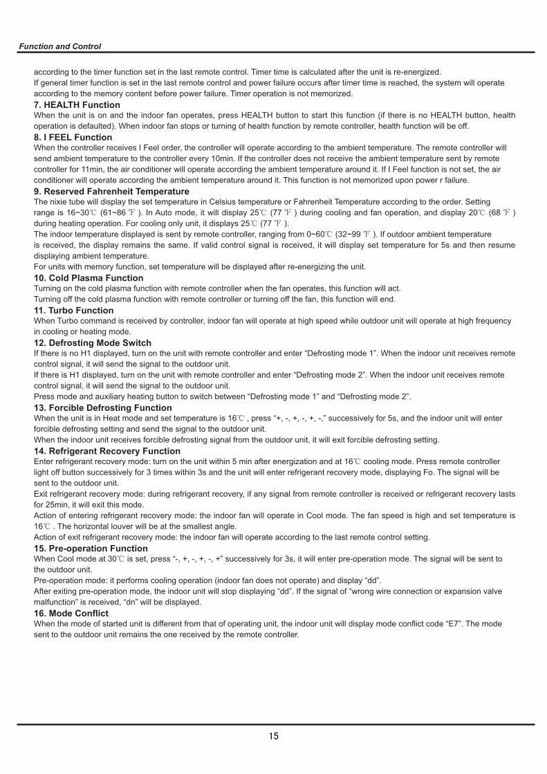
Tset
1H 2H 3H 4H
Tset-1℃
Tset-2℃
Tset-3℃
14
15

16

Space to the ceiling
Space to the wall
Space to the wall
Air outlet side Space to the floor
Above Above
Above
15cm Above 15cm Above
15cm
300cm 250cm
17
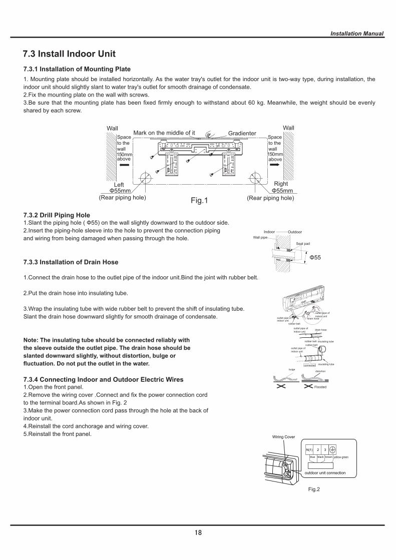
Indoor Outdoor Wall pipe
Seal pad
bulgedistortion
outlet pipe of indoor unit
insulating tubeconnected
insulating tube
drain hoseoutlet pipe of indoor unit
drain hose
outlet pipe of indoor unit
outlet pipe of indoor unit
rubber belt
rubber beltrubber belt
Flooded
Wall Wall Mark on the middle of it Gradienter
Left Right
(Rear piping hole) (Rear piping hole)
Space to the wall
above
Space to the wall
above 1 5 0mm 1 5 0mm
Fig.1 Φ55mm Φ55mm
yellow-green
Fig.2
N(1)
black
2 3
brownblue
Wiring Cover
outdoor unit connection
18
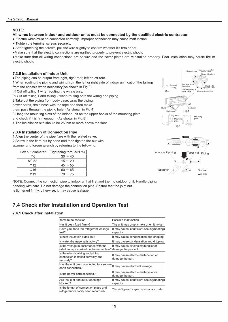
Spanner Torque wrench
PipingTaper nutIndoor unit piping
Fig.5
Mountingplate
Fixing hook Mounting plate
Right
Right rear Fig.4Left rear
Left
Fig.3Tailing 1Tailing 2
Finally wrap itwith tape
Gas side pipinginsulation
Water drainage pipe
Liquid sidePiping insulation
Gas side pipeExternal connection
electric wireLiquid side piping
Hex nut diameter Tightening torque(N·m)Ф6 30 40
Ф9.52 15 20Ф12 45 55Ф16 60 65Ф19 70 75
19

Fig. a
filter
Air filter
Fig. b
Fig. c
Healthy
20
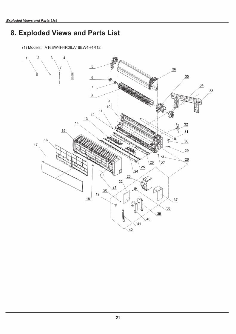
A16EW4H4R09,A16EW4H4R12
2 3 4
1716
15
1413
1211
10
8
7
36
34
35
33
32
31
30
29
28
2322
2120
4041
19
42
39
1
6
5
9
252726
18
38
24
37
21

A16EW4H4R09 A16EW4H4R12
22
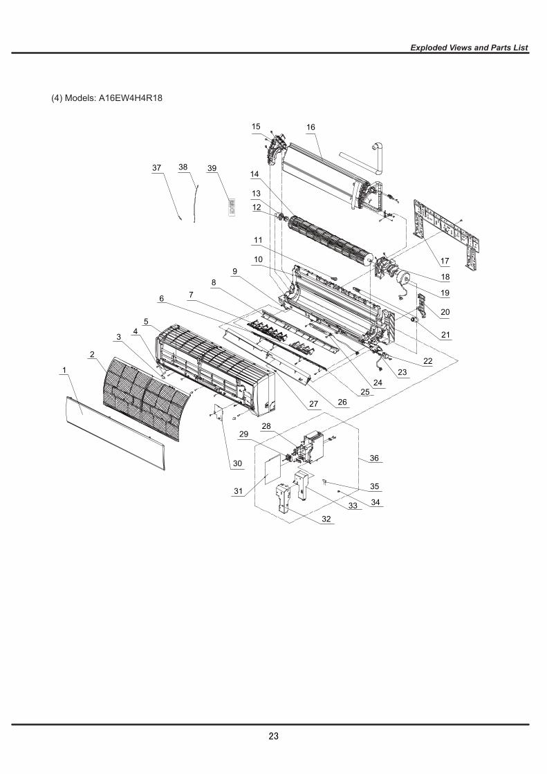
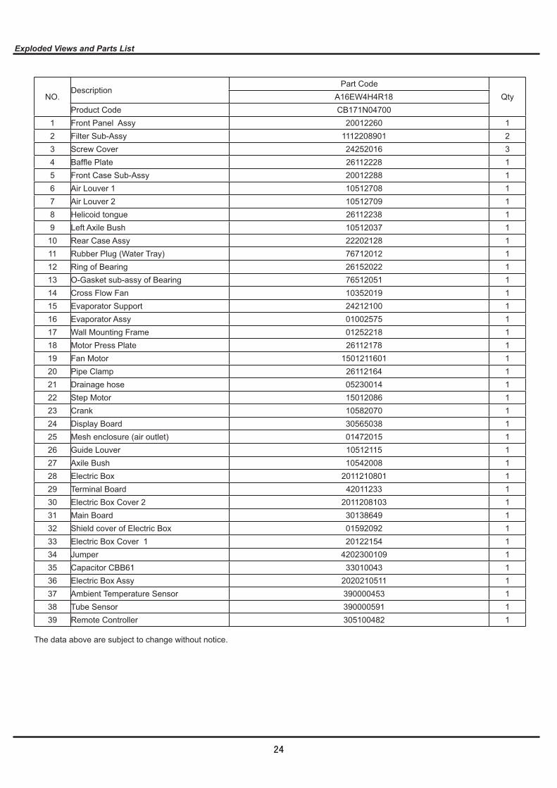
A16EW4H4R18
12
35
36
4
6
38
25
28
16
14
13
15
109
7
5
2
31
33 34
27 26
24
18
29
8
32
30
3
1
11
17
19
20
21
2322
37 39
23
A16EW4H4R18
24
25

26
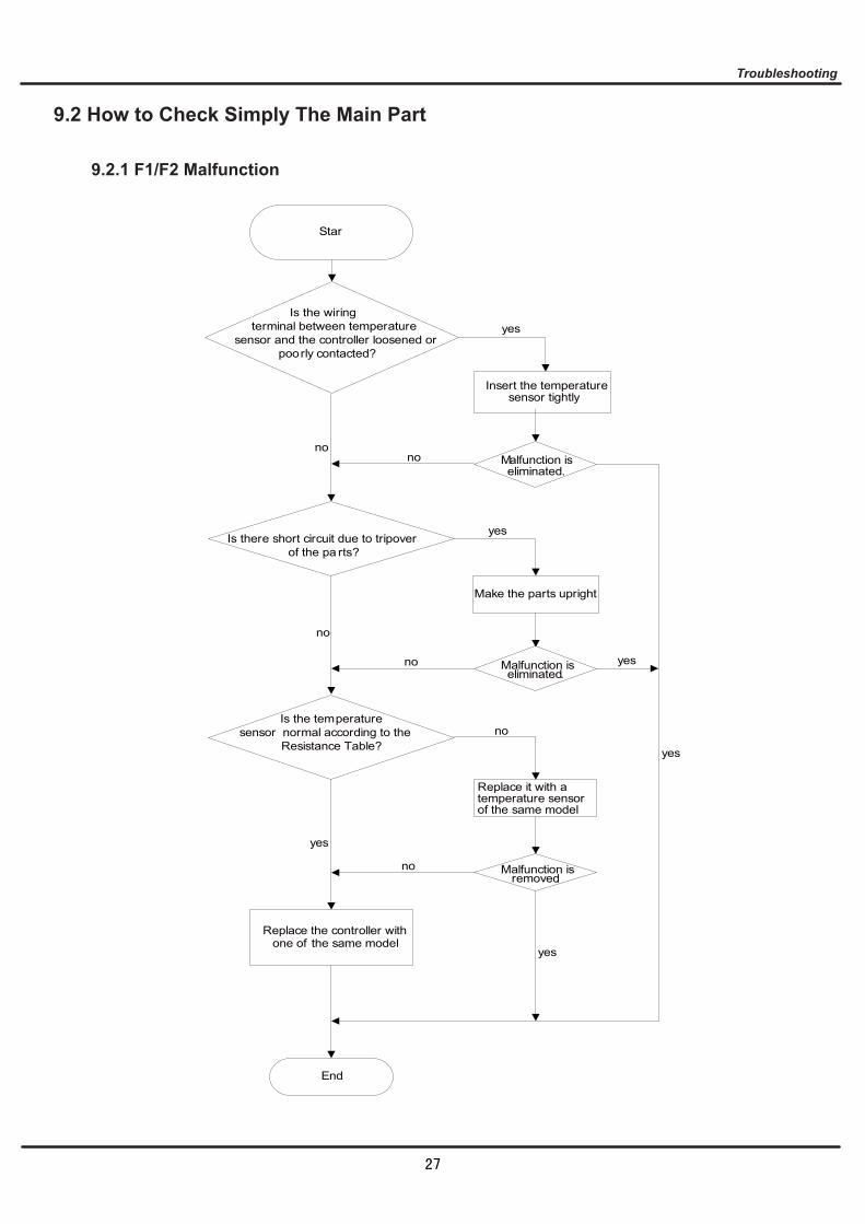
Star
Insert the temperature sensor tightly
yes
Malfunction is eliminated.
Make the parts upright
yes
Malfunction is eliminated.
Replace the controller with one of the same model
End
no
no
no
yes
yes
Malfunction is removed.
no
yes
yes
no
Is the wiring terminal between temperature sensor and the controller loosened or poorly contacted?
Is there short circuit due to tripover of the pa rts?
Is the temperature sensor normal according to the Resistance Table?
Replace it with a temperature sensor of the same model
no
27
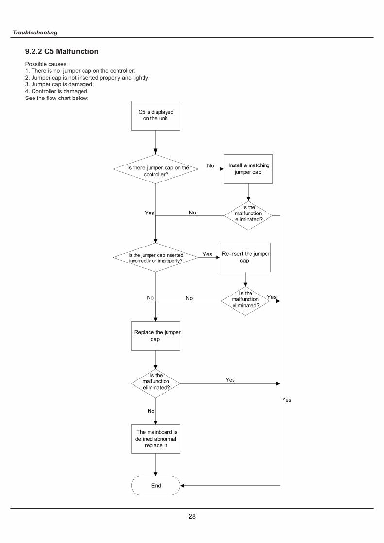
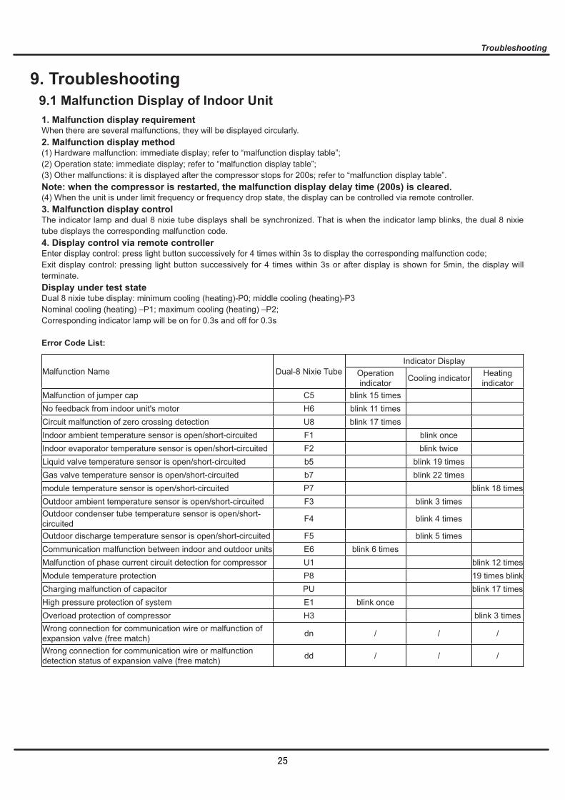
C5 is displayed on the unit.
Is there jumper cap on the controller?
Install a matching jumper cap.
No
Is the jumper cap inserted incorrectly or improperly?
Re-insert the jumper cap
The mainboard is defined abnormal
replace it
Yes
No
Yes
End
Is the malfunction eliminated?
Yes
No
No Yes
Replace the jumper cap
No
Yes
Is the malfunction eliminated?
Is the malfunction eliminated?
28
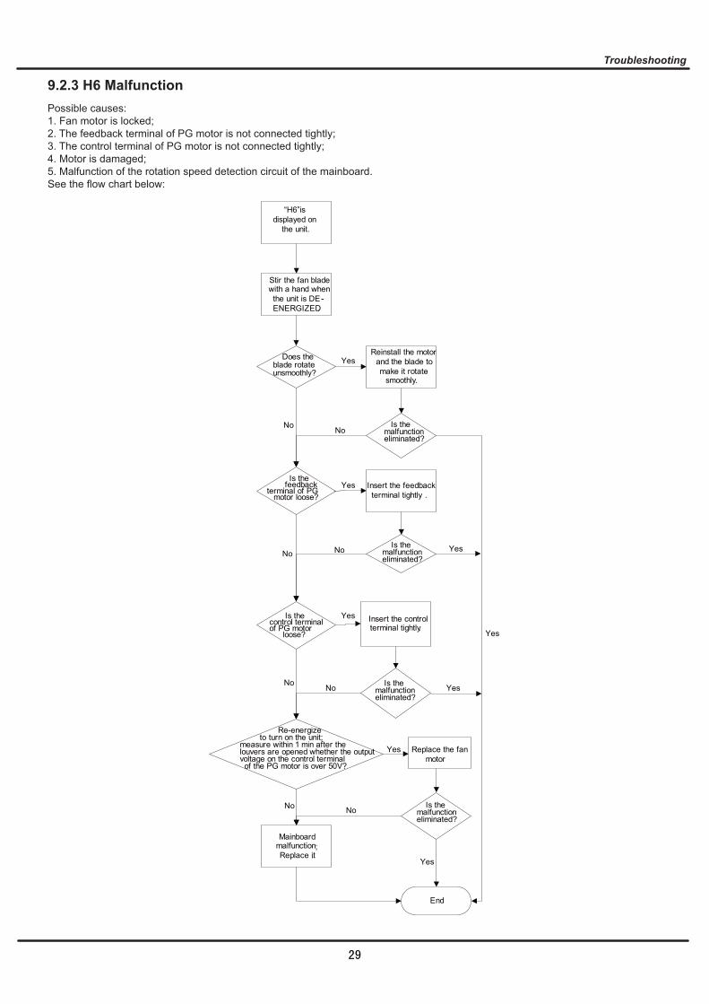
Stir the fan blade with a hand when the unit is DE-ENERGIZED.
Does the blade rotate unsmoothly?
Reinstall the motor and the blade to make it rotate
smoothly.
Yes
Is the feedback terminal of PG motor loose?
Insert the feedback terminal tightly .
Mainboard malfunction; Replace it.
No
Yes
Replace the fan motor
End
Insert the control terminal tightly.
Yes
No
Re-energize to turn on the unit; measure within 1 min after the louvers are opened whether the output voltage on the control terminal of the PG motor is over 50V?
No
Yes
No
Is the malfunction eliminated?
No
Is the malfunction eliminated?
No
No
No
Yes
Yes
Yes
Yes
Is the control terminal of PG motor loose?
Is the malfunction eliminated?
Is the malfunction eliminated?
“H6”is displayed on the unit.
29
Malfunction is eliminated.
No
Yes
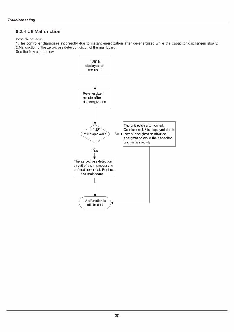
“U8” is displayed on the unit.
Re-energize 1 minute after de-erergization
Is“U8”still displayed?
The zero-cross detection circuit of the mainboard is defined abnormal. Replace the mainboard.
The unit returns to normal. Conclusion: U8 is displayed due to instant energization after de-energization while the capacitor discharges slowly.
30
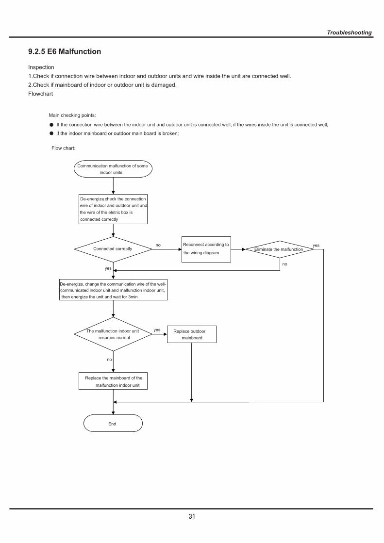
Main checking points:
If the indoor mainboard or outdoor main board is broken;
If the connection wire between the indoor unit and outdoor unit is connected well, if the wires inside the unit is connected well;
Flow chart:
Eliminate the malfunction
End
Communication malfunction of someindoor units
De-energize, check the connectionwire of indoor and outdoor unit and the wire of the eletric box isconnected correctly
no
no
no
Connected correctlyReconnect according to
the wiring diagram
yes
yes
yes
De-energize, change the communication wire of the well-communicated indoor unit and malfunction indoor unit,then energize the unit and wait for 3min
The malfunction indoor unitresumes normal
Replace outdoor mainboard
Replace the mainboard of the
malfunction indoor unit
31
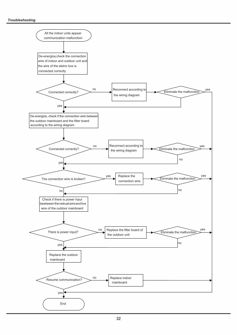
Eliminate the malfunction
Eliminate the malfunction
Eliminate the malfunction
Eliminate the malfunction
End
no
no
no
nono
no
no
no
yes
yes
yes
yes
yes
yes
yes
yes
yes
All the indoor units appear communication malfunction
De-energize, check the connectionwire of indoor and outdoor unit and the wire of the eletric box isconnected correctly
Connected correctly?Reconnect according to
the wiring diagram
Connected correctly?Reconnect according to the wiring diagram
De-energize, check if the connection wire betweenthe outdoor mainboard and the filter boardaccording to the wiring diagram
The connection wire is broken?Replace the connection wire
Check if there is power input bewtween the netrual wire and livewire of the outdoor mainboard
There is power input? Replace the filter board of the outdoor unit
Resume communication?
Replace the outdoor mainboard
Replace indoor mainboard
32
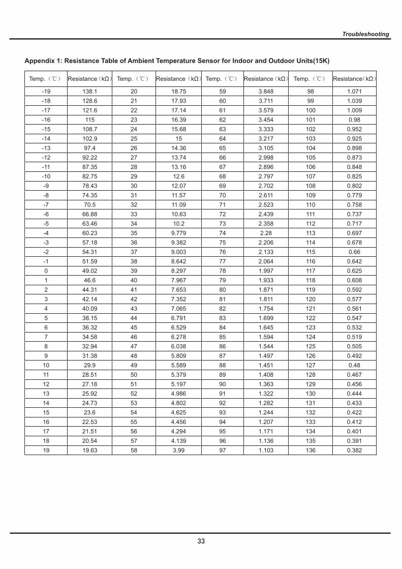
Temp. Resistance kΩ Temp. Resistance kΩ Temp. Resistance kΩ Temp. Resistance kΩ
-19 138.1 20 18.75 59 3.848 98 1.071-18 128.6 21 17.93 60 3.711 99 1.039-17 121.6 22 17.14 61 3.579 100 1.009-16 115 23 16.39 62 3.454 101 0.98-15 108.7 24 15.68 63 3.333 102 0.952-14 102.9 25 15 64 3.217 103 0.925-13 97.4 26 14.36 65 3.105 104 0.898-12 92.22 27 13.74 66 2.998 105 0.873-11 87.35 28 13.16 67 2.896 106 0.848-10 82.75 29 12.6 68 2.797 107 0.825-9 78.43 30 12.07 69 2.702 108 0.802-8 74.35 31 11.57 70 2.611 109 0.779-7 70.5 32 11.09 71 2.523 110 0.758-6 66.88 33 10.63 72 2.439 111 0.737-5 63.46 34 10.2 73 2.358 112 0.717-4 60.23 35 9.779 74 2.28 113 0.697-3 57.18 36 9.382 75 2.206 114 0.678-2 54.31 37 9.003 76 2.133 115 0.66-1 51.59 38 8.642 77 2.064 116 0.6420 49.02 39 8.297 78 1.997 117 0.6251 46.6 40 7.967 79 1.933 118 0.6082 44.31 41 7.653 80 1.871 119 0.5923 42.14 42 7.352 81 1.811 120 0.5774 40.09 43 7.065 82 1.754 121 0.5615 38.15 44 6.791 83 1.699 122 0.5476 36.32 45 6.529 84 1.645 123 0.5327 34.58 46 6.278 85 1.594 124 0.5198 32.94 47 6.038 86 1.544 125 0.5059 31.38 48 5.809 87 1.497 126 0.492
10 29.9 49 5.589 88 1.451 127 0.4811 28.51 50 5.379 89 1.408 128 0.46712 27.18 51 5.197 90 1.363 129 0.45613 25.92 52 4.986 91 1.322 130 0.44414 24.73 53 4.802 92 1.282 131 0.43315 23.6 54 4.625 93 1.244 132 0.42216 22.53 55 4.456 94 1.207 133 0.41217 21.51 56 4.294 95 1.171 134 0.40118 20.54 57 4.139 96 1.136 135 0.39119 19.63 58 3.99 97 1.103 136 0.382
Appendix 1: Resistance Table of Ambient Temperature Sensor for Indoor and Outdoor Units(15K)
33
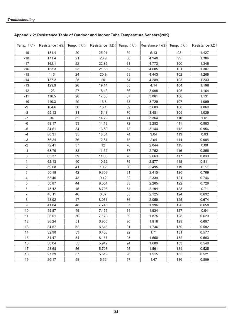
Temp. Resistance kΩ Temp. Resistance kΩ Temp. Resistance kΩ Temp. Resistance kΩ
-19 181.4 20 25.01 59 5.13 98 1.427-18 171.4 21 23.9 60 4.948 99 1.386-17 162.1 22 22.85 61 4.773 100 1.346-16 153.3 23 21.85 62 4.605 101 1.307-15 145 24 20.9 63 4.443 102 1.269-14 137.2 25 20 64 4.289 103 1.233-13 129.9 26 19.14 65 4.14 104 1.198-12 123 27 18.13 66 3.998 105 1.164-11 116.5 28 17.55 67 3.861 106 1.131-10 110.3 29 16.8 68 3.729 107 1.099-9 104.6 30 16.1 69 3.603 108 1.069-8 99.13 31 15.43 70 3.481 109 1.039-7 94 32 14.79 71 3.364 110 1.01-6 89.17 33 14.18 72 3.252 111 0.983-5 84.61 34 13.59 73 3.144 112 0.956-4 80.31 35 13.04 74 3.04 113 0.93-3 76.24 36 12.51 75 2.94 114 0.904-2 72.41 37 12 76 2.844 115 0.88-1 68.79 38 11.52 77 2.752 116 0.8560 65.37 39 11.06 78 2.663 117 0.8331 62.13 40 10.62 79 2.577 118 0.8112 59.08 41 10.2 80 2.495 119 0.773 56.19 42 9.803 81 2.415 120 0.7694 53.46 43 9.42 82 2.339 121 0.7465 50.87 44 9.054 83 2.265 122 0.7296 48.42 45 8.705 84 2.194 123 0.717 46.11 46 8.37 85 2.125 124 0.6928 43.92 47 8.051 86 2.059 125 0.6749 41.84 48 7.745 87 1.996 126 0.65810 39.87 49 7.453 88 1.934 127 0.6411 38.01 50 7.173 89 1.875 128 0.62312 36.24 51 6.905 90 1.818 129 0.60713 34.57 52 6.648 91 1.736 130 0.59214 32.98 53 6.403 92 1.71 131 0.57715 31.47 54 6.167 93 1.658 132 0.56316 30.04 55 5.942 94 1.609 133 0.54917 28.68 56 5.726 95 1.561 134 0.53518 27.39 57 5.519 96 1.515 135 0.52119 26.17 58 5.32 97 1.47 136 0.509
Appendix 2: Resistance Table of Outdoor and Indoor Tube Temperature Sensors(20K)
34

Temp.Resistance
kΩTemp. Resistance kΩ Temp. Resistance kΩ Temp. Resistance kΩ
-29 853.5 10 98 49 18.34 88 4.754-28 799.8 11 93.42 50 17.65 89 4.609-27 750 12 89.07 51 16.99 90 4.469-26 703.8 13 84.95 52 16.36 91 4.334-25 660.8 14 81.05 53 15.75 92 4.204-24 620.8 15 77.35 54 15.17 93 4.079-23 580.6 16 73.83 55 14.62 94 3.958-22 548.9 17 70.5 56 14.09 95 3.841-21 516.6 18 67.34 57 13.58 96 3.728-20 486.5 19 64.33 58 13.09 97 3.619-19 458.3 20 61.48 59 12.62 98 3.514-18 432 21 58.77 60 12.17 99 3.413-17 407.4 22 56.19 61 11.74 100 3.315-16 384.5 23 53.74 62 11.32 101 3.22-15 362.9 24 51.41 63 10.93 102 3.129-14 342.8 25 49.19 64 10.54 103 3.04-13 323.9 26 47.08 65 10.18 104 2.955-12 306.2 27 45.07 66 9.827 105 2.872-11 289.6 28 43.16 67 9.489 106 2.792-10 274 29 41.34 68 9.165 107 2.715-9 259.3 30 39.61 69 8.854 108 2.64-8 245.6 31 37.96 70 8.555 109 2.568-7 232.6 32 36.38 71 8.268 110 2.498-6 220.5 33 34.88 72 7.991 111 2.431-5 209 34 33.45 73 7.726 112 2.365-4 198.3 35 32.09 74 7.47 113 2.302-3 199.1 36 30.79 75 7.224 114 2.241-2 178.5 37 29.54 76 6.998 115 2.182-1 169.5 38 28.36 77 6.761 116 2.1240 161 39 27.23 78 6.542 117 2.0691 153 40 26.15 79 6.331 118 2.0152 145.4 41 25.11 80 6.129 119 1.9633 138.3 42 24.13 81 5.933 120 1.9124 131.5 43 23.19 82 5.746 121 1.8635 125.1 44 22.29 83 5.565 122 1.8166 119.1 45 21.43 84 5.39 123 1.777 113.4 46 20.6 85 5.222 124 1.7258 108 47 19.81 86 5.06 125 1.6829 102.8 48 19.06 87 4.904 126 1.64
Note: The information above is for reference only.
Appendix 3: Resistance Table of Outdoor Discharge Temperature Sensor(50K)
35

1.Remove the filter
Open the panel.
Loosen the clasp of the filter.
Remove axile bush of horizontallouver.
Push the filter inward and then raiseit to remove it.
2.Remove horizontal louver
1
2
3
1
panel
clasp
filter
axile bush
Steps Procedure
36

horizon-tal louver
Bend the horizontal louver slightly toremove it.
4.Remove electric box cover 2
3.Remove front panel
Slide the rotor shaft out of the groove.Remove the front panel.
rotor shaft
front panel
Remove the screws fixing the elec-tric box cover 2.
screw
1
2
1
Steps Procedure
37
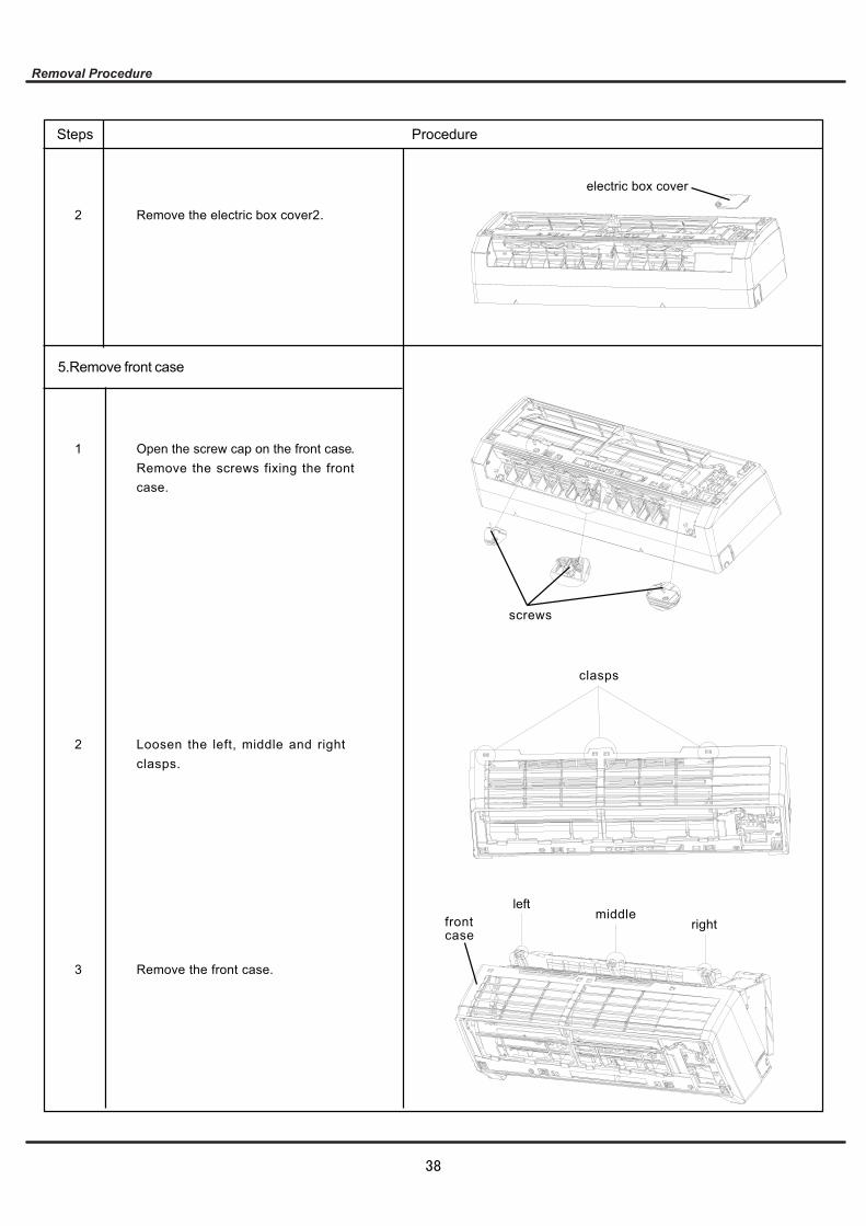
5.Remove front case
Open the screw cap on the front case.Remove the screws fixing the frontcase.
left
Remove the electric box cover2.
Loosen the left, middle and rightclasps.
screws
Remove the front case.
middlerightfront
case
2
1
2
3
electric box cover
clasps
Steps Procedure
38

6.Remove vertical louver
7.Remove electric box
Loosen the clasps connecting verticallouver with bottom case.
Disconnect the indoor pipe tempera-ture sensor.
Remove the screw of the electric box.
Remove the screws at the joint ofground wire and evaporator.
clasps
Remove the vertical louver.
Heat exchangerthermistor
vertical louver
screw
Ground Wire
2
2
1
1
3
screws
Steps Procedure
39
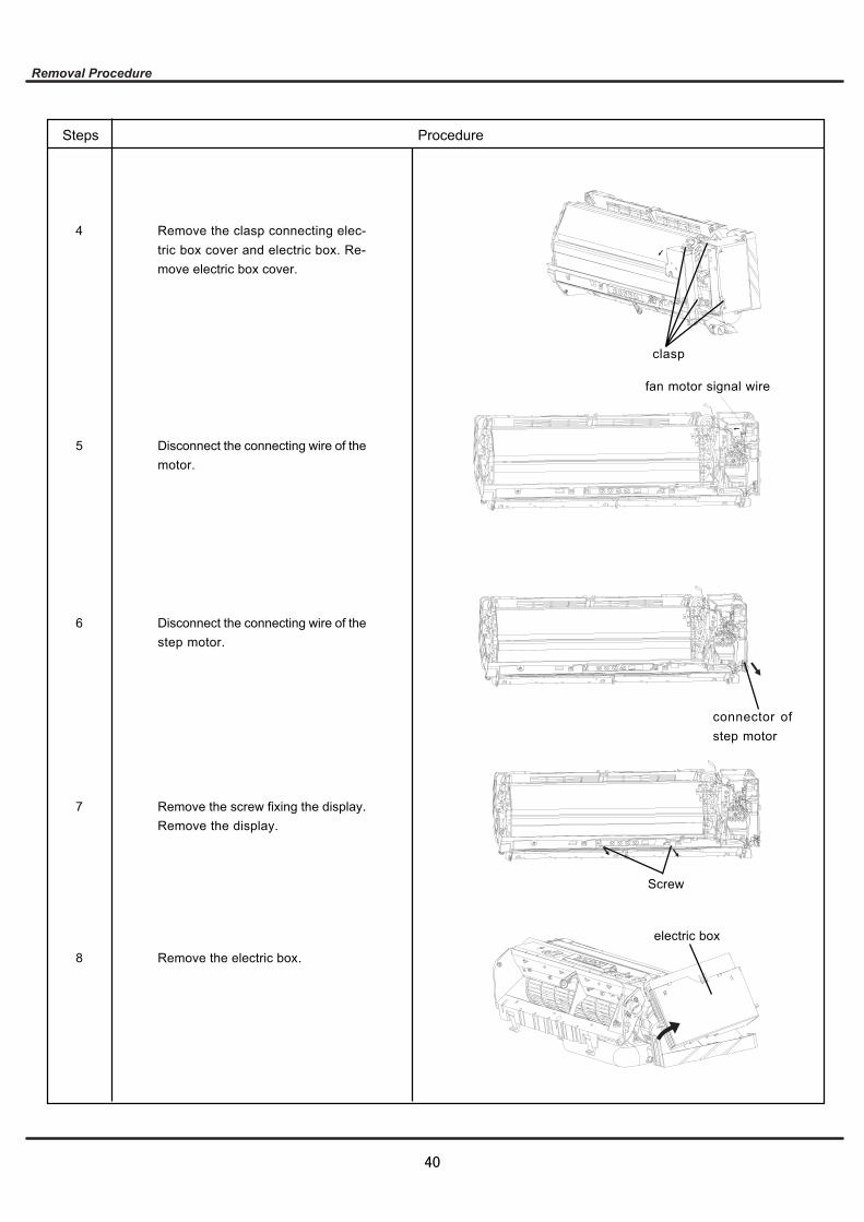
Remove the clasp connecting elec-tric box cover and electric box. Re-move electric box cover.
Disconnect the connecting wire of themotor.
Disconnect the connecting wire of thestep motor.
Remove the screw fixing the display.Remove the display.
Remove the electric box.
clasp
fan motor signal wire
connector ofstep motor
4
5
6
7
8
Screw
electric box
Steps Procedure
40
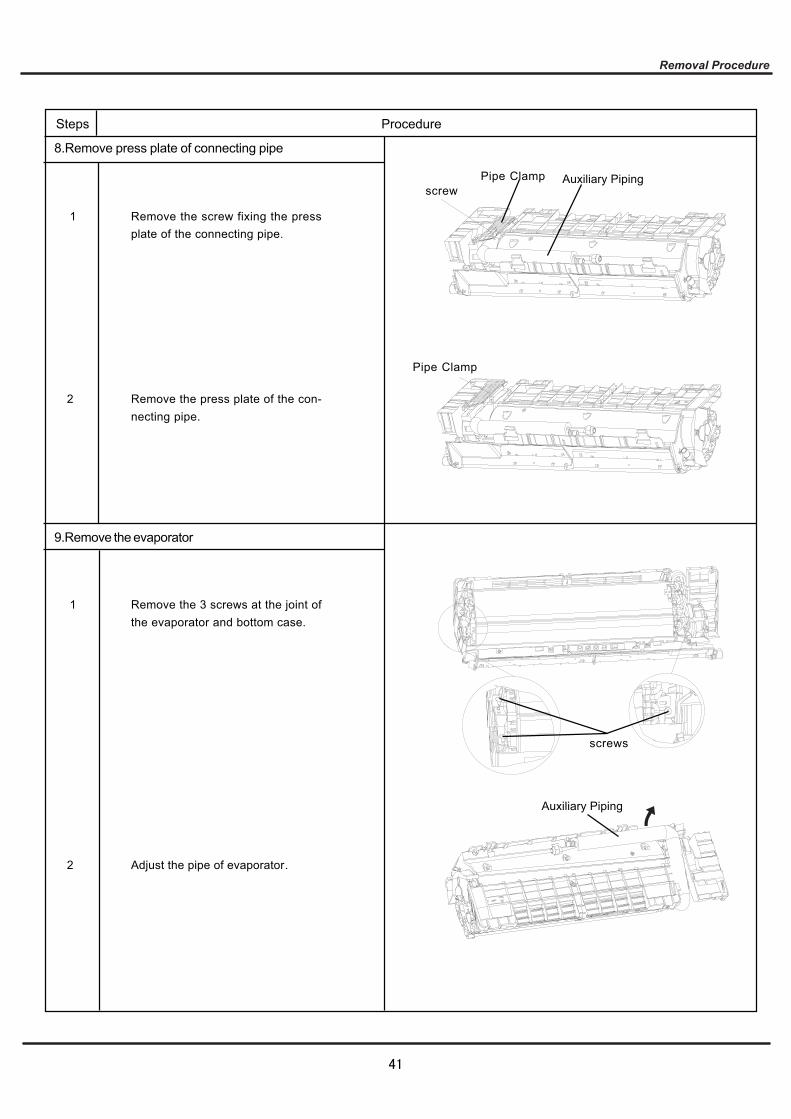
8.Remove press plate of connecting pipe
Remove the press plate of the con-necting pipe.
Remove the screw fixing the pressplate of the connecting pipe.
Auxiliary PipingPipe Clampscrew
Pipe Clamp
1
2
9.Remove the evaporator
Remove the 3 screws at the joint ofthe evaporator and bottom case.
Auxiliary Piping
Adjust the pipe of evaporator.
1
2
screws
Steps Procedure
41
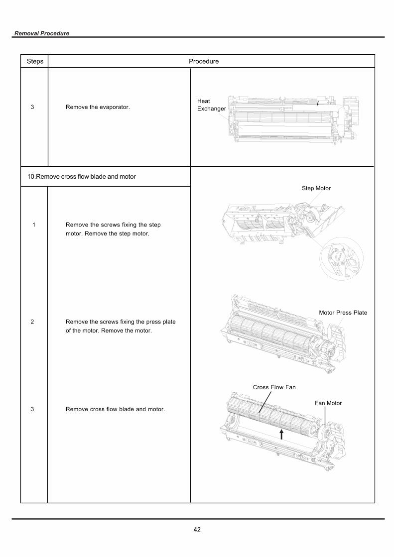
Remove the evaporator.
Remove the screws fixing the stepmotor. Remove the step motor.
10.Remove cross flow blade and motor
HeatExchanger
Step Motor
3
1
Remove the screws fixing the press plateof the motor. Remove the motor.
Remove cross flow blade and motor.
Motor Press Plate
Cross Flow Fan
Fan Motor
2
3
Steps Procedure
42
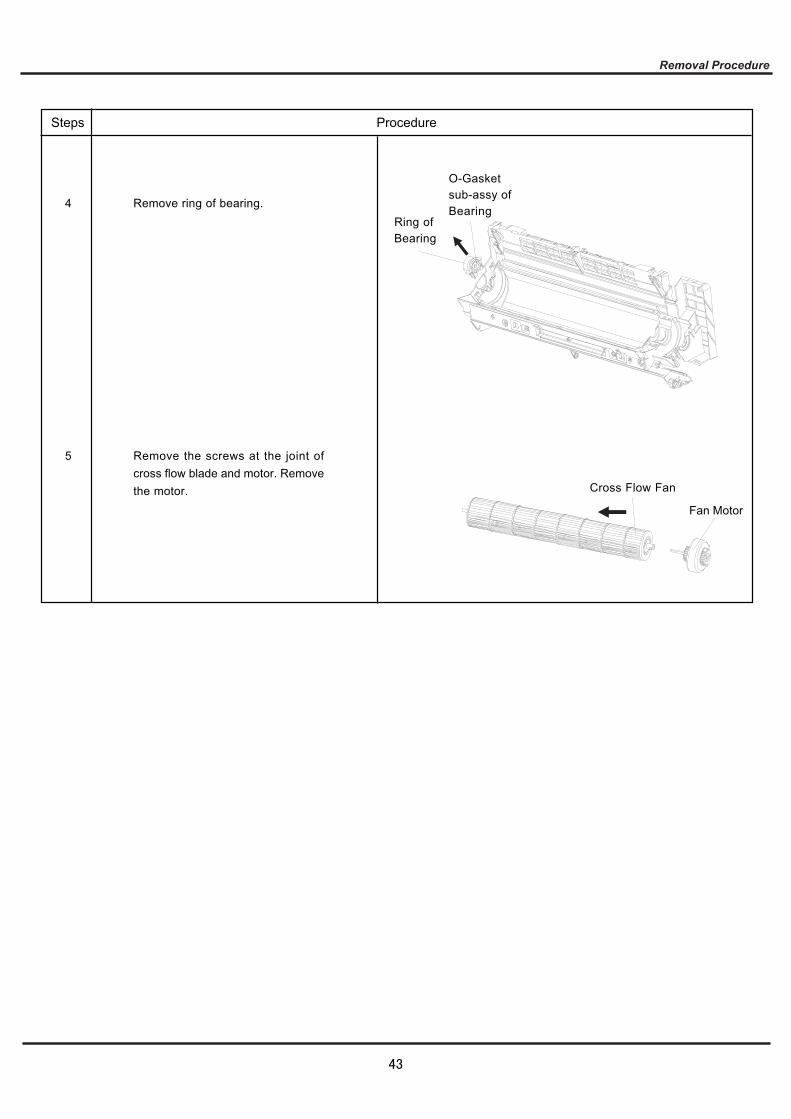
Remove the screws at the joint ofcross flow blade and motor. Removethe motor.
O-Gasketsub-assy ofBearing
Ring of Bearing
Remove ring of bearing.
Cross Flow Fan
Fan Motor
4
5
Steps Procedure
43