service manual, c842, c842i, c846, c846i bicycle · 2009-12-18 · c842, c842i, c846, c846i upright...
TRANSCRIPT
C842, C842i, C846, C846i Upright and Recumbent Cycle
C842, C842i, C846, C846i Bicycle
Warning: This service manual is for use by Precor trained service providers only.If you are not a Precor Trained Servicer, you must not attempt to service any Precor Product;
Call your dealer for service.
This document contains information required to perform the majority of troubleshooting, and replacement procedures required to repair and maintain this product.
This document contains general product information, software diagnostic procedures (when available), preventative maintenance procedures, inspection and adjustment procedures, troubleshooting procedures, replacement procedures and electrical block and wiring diagrams.
To move directly to a procedure, click the appropriate procedure in the bookmark section to the left of this page. You may “drag” the separator bar between this page and the bookmark section to change the size of the page being viewed.
© 2004 Precor Incorporated Unauthorized Reproduction and Distribution Prohibited By Law
Page 1
C842, C842i, C846, C846i Upright and Recumbent Cycle
Section One - Things You Should Know
Right, Left, Front, and Back Conventions
In this manual, right, left, front, and back are from the perspective of a user sitting on the C842 or C846, facing the display enclosure.
Identifying C846 Bicycles
Two generations of C842 and C846 bicycles have been manufactured.
The original version was first produce in January 1999. The original upright bicycle was manufactured under serial codes 6C, 7D, EH and ER. The original recumbent bicycle was manufactured under serial codes 6B, 7C, DM and EP. This bicycle utilized an alternator and load resistors to charge the internal battery and provide pedalling resistance.
The second generation C846 bicycle was first produced in February 2003. The C846 upright is manufactured under serial code NM, the C846 recumbent is manufactured under serial code NN. This bicycle utilizes a dual microprocessor control system, a touch sensitive keypad, a brushless generator to charge the internal battery and an eddy current system to provide pedalling resistance.
All C842 bicycles are second generation bicycles and were first produced on February 2003. The C842 upright is manufactured under serial code NK, the C842 recumbent is manufactured under serial code NL.
C846i bicycles were first produced in March 2004. The C846i upright is manufactured under serial code XE, the C846i recumbent is manufactured under serial code XX.
The C842i upright is manufactured under serial code AA28, the C842i recumbent is manufactured under serial code A993.
Warning and Caution Statements and General Safety Guidelines
Warning statements indicate a particularly dangerous activity. Warning statements you will find in this manual include:
• To remove power from the C842, C842i, C846 or C846i, the optional power adapter must be disconnected from the cycle. Always ensure that the optional power adapter is disconnected from the cycle when you inspect or adjust the C842, C842i, C846 or C846i, or when you isolate, remove, or replace a component.
• When serial code 6B, 6C, 7C, 7D, DM, DQ, EP or ER cycles are operated the load resistor will become very hot. During any service procedure, avoid contact with the load resistor or be sure that the load resistor has cooled sufficiently to be safely handled.
Page 2
C842, C842i, C846, C846i Upright and Recumbent Cycle
• Removing the covers exposes high voltage components and potentially dangerous moving parts. Exercise extreme caution when you perform maintenance procedures with the hood removed.
• During service operations you will be very close to moving machinery and high voltage components. When you perform maintenance procedures with the covers removed, remove jewelry (especially from ears and neck), tie up long hair, remove neck ties, and do not wear loose clothing.
• Exercise caution when touching any wire or electrical component during operation.
• Caution statements are intended to prevent damage to the bicycle as a result of the current activity. Caution statements included in this manual are listed below:
Safety guidelines you should know and follow include:
• Read the owner’s manual and follow all operating instructions.
• Visually check the bicycle before beginning service or maintenance operations. If it is not completely assembled or is damaged in any way, exercise extreme caution while operating and checking the bicycle.
• When operating the bicycle, do not wear loose clothing. Do not wear shoes with heels or leather soles. Check the soles of your shoes and remove any embedded stones. Tie long hair back.
• Do not rock the unit. Do not stand or climb on the handlebars, display enclosure, or cover.
• Do not set anything on the handlebars, display enclosure, or cover. While servicing, never place liquids on any part of the bicycle The water bottle holder must be empty.
• To prevent electrical shock, keep all electrical components, such as the power cord and power adapters away from water and other liquids.
• Do not use accessory attachments that are not recommended by the manufacturer, such attachments might cause injuries or damage to the unit.
General Information
For the latest exploded view diagram, part number and part pricing information, visit the Precor dealer website at “www.precor.com/connection”.
Page 3
C842, C842i, C846, C846i Upright and Recumbent Cycle
Required Tools and Equipment
The following is a summary of the tools and equipment that may be required when you service a Precor C842, C842i, C846 or C846i Upright or Recumbent Cycle.
Tools
Phillip and flat-head screwdriversStandard and metric allen wrench setOpen-end wrench setSocket wrench setChip pullerRubber malletSnap ring pliersTorque wrenchPry bar20030-119 secondary sheave tool32 mm deep well socket
Equipment
Anti-static kitDigital multimeter
Supplies
Cable ties
Page 4
C842, C842i, C846, C846i Upright and Recumbent Cycle
Section Two - Preventive Maintenance
Preventive maintenance measures are either scheduled or unscheduled. Scheduled preventive maintenance activities are included here so that you are aware of preventive measures performed on a regular basis.
Regular Preventive Maintenance (Owner)
Cleanliness of the cycle and its operating environment will keep maintenance problems and service calls to a minimum. Precor recommends that you perform the following preventive maintenance schedule.
After Each Use
• Turn off and, unplug the power adapter (if equipped) from the bicycle.
• Wipe down the covers, handlebars, seat and pedals with a damp cloth.
Daily Maintenance
Clean the bicycle’s frame, covers, seat and pedals using a water damped cloth. Wipe the surface of the electronic console with a damp sponge or soft cloth. Dry with a clean towel.
Weekly Maintenance
• Clean underneath the bicycle, following these steps:
1. Turn off the bicycle with the on/off switch, then unplug it from the power adapter (if equipped).
2. Place the bicycle on its side.
Note:Place a drop cloth under the bicycle to protect the flooring and to ensure that the cycle handrail is not scratched or damaged.
3. Vacuum the rug or damp mop the floor.
4. Make sure that the floor is dry before returning the bicycle to an upright position.
Page 5
C842, C842i, C846, C846i Upright and Recumbent Cycle
Quarterly Maintenance
1. Remove the cover.
2. Thoroughly clean inside the bicycle. Use a vacuum cleaner and damp rag all dust belt particles, etc.
3. Check the belt tension of both belts per Procedures 5.1 and 5.2.
4. Replace both covers.
On-Site Preventive Maintenance (Service Technician)
When you are called to service a C842, C842i, C846 or C846i, perform these preventive maintenance activities:
• Perform the software diagnostics. Check LED and keypad function. Record the odometer reading. See Procedure 3.1.
• Check speed sensor function (is RPM or speed displayed when the unit is in operation?). If not, see Procedure 6.4
• If the unit is operated at resistance level 1, does it turn freely and smoothly? If not, see Procedure 6.6.
• Visually inspect the drive belts for cracks, fraying or excessive wear.
• Visually examine all wires and check connectors and wire connections. Secure connections and replace wiring as necessary.
Page 6
C842, C842i, C846, C846i Upright and Recumbent Cycle
Procedure 3.1 - Software Access Codes
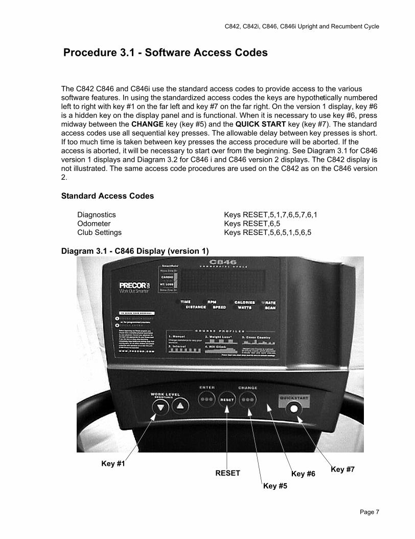
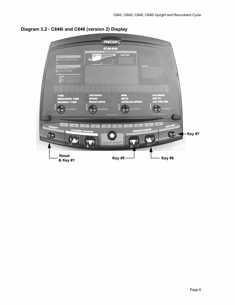
The C842 C846 and C846i use the standard access codes to provide access to the various software features. In using the standardized access codes the keys are hypothetically numbered left to right with key #1 on the far left and key #7 on the far right. On the version 1 display, key #6 is a hidden key on the display panel and is functional. When it is necessary to use key #6, press midway between the CHANGE key (key #5) and the QUICK START key (key #7). The standard access codes use all sequential key presses. The allowable delay between key presses is short. If too much time is taken between key presses the access procedure will be aborted. If the access is aborted, it will be necessary to start over from the beginning. See Diagram 3.1 for C846 version 1 displays and Diagram 3.2 for C846 i and C846 version 2 displays. The C842 display is not illustrated. The same access code procedures are used on the C842 as on the C846 version 2.
Standard Access Codes
Diagnostics Keys RESET,5,1,7,6,5,7,6,1 Odometer Keys RESET,6,5 Club Settings Keys RESET,5,6,5,1,5,6,5
Diagram 3.1 - C846 Display (version 1)
Key #1RESET
Key #5Key #6 Key #7
Page 7
C842, C842i, C846, C846i Upright and Recumbent Cycle
Diagram 3.2 - C846i and C846 (version 2) Display
Key #7
Key #6Key #5Reset& Key #1
Page 8
C842, C842i, C846, C846i Upright and Recumbent Cycle
Procedure 3.2 - Accessing the Diagnostic Program
The C846 diagnostic software cycles through the following tests:
C846 version 1 C846 i & C846 version 2 C842 & C842i• LED Diagnostics LED Diagnostics Display Test• Keypad Test Keypad Test Keyboard Test• Power Bits/Speed Heart Rate Heart Rate Test• Heart Rate Battery Voltage Display Battery Test• Battery Voltage Display RPM Test RPM Test• Brake Test Brake Test
Procedure
1. On C846 version 1 units, set the on/off switch in the “on” position. It will be necessary to start pedaling for the bicycle to “power up”. You must continue pedaling while performing this procedure.
2. With the start up banner displayed press keys RESET,5,1,7,6,5,7,6,1, sequentially.
3. For C842 and C842i units, skip to step 24. For C846i and C846 version 2 units, skip to step 11. For C846 version 1 units, continue with step 4.
4. Watch the upper display, all LED’s in the main window and the eight LED’s below the main window should be lit.
5. Press any key to continue with the key pad test.
6. The display will show seven vertical rows of two dots each. Each row corresponds to a key on the display. Press each of the seven keys, including the hidden key between the CHANGE and QUICK START key, the corresponding row will expand to six dots. Press and hold the RESET key to continue.
7. Power bits indicates the amount of power required to pedal the bike. The power bits are adjustable between 0 and 255 by using the or keys. The greater the power bits number the greater the pedaling resistance. Press ENTER to toggle the display between power bits and speed. Press the RESET key to continue to the heart rate test.
8. The left side of the window displays a “U F P”. the right side displays the heart rate, when a signal is received from a chest strap or test transmitter. The U indicates unfiltered, the F indicates filtered and P indicates Polar. The ENTER toggles through the three choices. When unfiltered is selected the heart rate display will show heart rate as received from the transmitter. When filtered is selected the heart rate signal will be averaged and displayed. When Polar is selected, the Polar method of filtering will be used and the results displayed. The Polar method of filtering is used during normal operation. Press and hold the RESET key to display the battery voltage level display
Page 9
C842, C842i, C846, C846i Upright and Recumbent Cycle
9. The battery voltage level will be displayed. Typically, the battery voltage level will be between 6.0 Vdc and 6.2 Vdc. A battery charger in the bike charges the battery as the bike is pedaled. If the battery voltage will not come up to 6.0 Vdc when the bike has been pedaled for several minutes or decreases very rapidly when then bike is not being pedaled, the battery should be replaced. Press the RESET key to exit the diagnostics routine.
10. The display will momentarily read HARDWARE VALIDATION.
11. Watch the upper display, all LED’s on the display should be lit.
12. Press the ENTER to continue to the key pad test.
13. The display will momentarily read KEYBOARD TEST.
14. The display will show a vertical rows of two dots each to represent each key on the keypad. Press each of the keys, upper dot in each key representation will go out when the key is pressed. Press and hold the ENTER key to continue.
15. The display will momentarily read HEART RATE TEST.
16. “U F P”. will be displayed. Grasp the hand held heart rate grips on the seat handlebars. The U indicates unfiltered, the F indicates filtered and P indicates Polar. Release the hand held heart rate grips and repeat the test using a chest strap transmitter or heart rate test transmitter. Verify that both the hand held and wireless (chest strap) readings are correct. A Polar watch is a good means of verifying the accuracy of the heart rate readings. Press the ENTER key to continue.
17. The display will momentarily read BATTERY TEST.
18. The current battery voltage will be displayed as XX.X VOLTS. Press the ENTER key to continue.
19. The display will momentarily read RPM TEST.
20. The display will show the pulse count from the display and the bike’s sped in RPM.
21. The display will momentarily read BRAKE TEST.
22. The display will show the current resistance level setting and the eddy current power bits reading (BRAKE). Using the resistance or keys, change the resistance level. The power bits reading should increase or decrease proportionally to the resistance level setting and the pedalling resistance should also increase or decrease proportionally to the resistance level setting
23. Press the ENTER or RESET key to exit the diagnostics program.
24. The message DISPLAY TEST will be momentarily displayed. All of the LED’s on the display will then be illuminated.
25. Press the SELECT key to continue to the keyboard test.
Page 10
C842, C842i, C846, C846i Upright and Recumbent Cycle
26. The message KEYBOARD TEST will be momentarily displayed. A representation of each key on the keyboard will be displayed. Pressing a key will cause the representation to change, indicating that the key is functioning normally. Test all of the keyboard keys in this manner.
27. Press the SELECT key to continue to the heart rate test.
28. The Polar filtered heart rate will be displayed as P XX. Pressing the SELECT key will toggle the display to the filtered heart rate, displayed as F XX. Pressing the SELECT key again will toggle the display the unfiltered heart rate, displayed as U XX.
29. Press the RESET key to continue to the battery test.
30. The message BATTERY TEST will be momentarily displayed.
31. A message will scroll indicating that the optional external is or is not connected. Pressing the SELECT key will cause a message to be displayed indicating the battery condition. Pressing the SELECT key again will display the actual battery voltage as BATTERY XX.X.
32. Press the RESET key to continue to the RPM test.
33. The message RPM TEST will be momentarily displayed.
34. The message RPM PULSE will be momentarily displayed, followed by the actual RPM reading.
35. Press the SELECT key to continue to the brake test.
36. The message BRAKE TEST will be momentarily displayed.
37. The message POWER BITS will be momentarily displayed, followed by the power bit reading. The power bit reading will change in correspondence with any change in the resistance level. Pressing the SELECT key will toggle the display to the resistance level.
38. The message RESISTANCE LEVEL will be momentarily displayed, followed by the current resistance level setting.
39. Press the RESET key to exit the program.
Page 11
C842, C842i, C846, C846i Upright and Recumbent Cycle
Procedure 3.3 - Displaying the Odometer
Procedure
1. For C846 version 1 units, set the on/off switch in the “on” position. You must continue pedaling while performing this procedure.
2. With the banner scrolling, press keys RESET,6,5, sequentially until the message. The total revolutions will be displayed.
3. For C842 and C842i units, skip to step 19. For C846i and C846 version 2 units, skip to step 8. For C846 version 1 units, continue with step 4.
4. Press the ENTER key and the total hours of usage will be displayed.
5. Press the ENTER key and the software version will be displayed.
6. Press the ENTER key and the first entry of error code log will be displayed. Use the and keys to view all of the error code log entries.
7. Press and hold the RESET key to exit the ODOMETER program.
8. The display will momentarily read INFORMATION DISPLAY.
9. The display will momentarily read ODOMETER.
10. The odometer will be displayed as XXXXX REVOLUTIONS. Press the ENTER key to continue to the hour meter display.
11. The display will momentarily read HOUR METER.
12. The hour meter will be displayed as XXX HOURS. Press the ENTER key to continue to the software version display.
13. The display will momentarily read SOFTWARE VERSION.
14. The software versions will be displayed as UPPER X.XX LOWER X.XX. Press the ENTER key to continue to the error log display.
15. The first (most recent) error will be displayed or the message NO ERRORS will be displayed if the log is empty. The and keys will move you through the log. Pressing and holding the QUICK START will allow you to clear the error log. Press the ENTER key to continue to the serial number display
16. The display will momentarily read SERIAL NUMBER.
Page 12
C842, C842i, C846, C846i Upright and Recumbent Cycle
17. The serial number of the unit will be displayed or NO SERIAL NUMBER. If a serial number has not been entered into memory. The serial number is in the upper PCA memory, therefore if the upper PCA is replaced or installed on a different C846 the serial number will be lost or incorrect.
18. Press the ENTER or RESET key to exit the program.
19. The odometer will be displayed, in total revolutions, as REVOLUTIONS XXXXXX.
20. Press the SELECT key to continue to the total hours display.
21. The total hours the bike has been used will be displayed as HOURS XXXX.
22. Press the SELECT key to continue to the software display.
23. The upper and lower software versions will be displayed as UPPER SW: VER XX.X LOWER SW: VER XX.X.
24. Press the SELECT key to continue to the error log.
25. The first (most recent) error will be displayed or the message NO ERRORS will be displayed if the log is empty. The and keys will move you through the log. Pressing and holding the QUICK START will allow you to clear the error log.
26. Press the RESET key to exit the program.
Page 13
C842, C842i, C846, C846i Upright and Recumbent Cycle
Procedure 3.4 - Club Settings
1. For C846 version 1 units, set the on/off switch in the “on” position.
2. On all versions, you must continue pedaling while performing this procedure.
3. For C842 and C842i units, skip to step 23. For C846i and C846 version 2 units, skip to step 11. For C846 version 1 units, continue with step 3.
4. Enter the club settings by pressing keys RESET,5,6,5,1,5,6,5, sequentially.
5. Either U.S. STANDARD or METRIC will be displayed. Use either of the or keys to select the desired setting.
6. Press the ENTER key to continue.
7. The maximum workout time will be displayed. The maximum workout may be selected with either of the or keys. Press ENTER to continue.
8. The maximum workout time is displayed on the display window. The maximum workout time is the maximum time a user is allowed to use the unit.
9. The maximum workout time is adjustable between 10 and 240 minutes. If you wish to change the maximum workout time...
THEN... OTHERWISE...Use the or keys to select Continue with the next step.the new maximum workout time;then continue with the next step.
10. Press and hold the RESET key to exit the program.
11. Enter the club settings by pressing keys RESET,5,6,5,1,5,6,5, sequentially.
12. The display will momentarily read SET CLUB PARAMETERS.
13. The display will momentarily read SELECT UNITS.
14. Either U.S. STANDARD or METRIC will be displayed. Use the either of the or keys to select the desired setting.
15. The display will momentarily read SET MAX WORKOUT TIME.
16. The current maximum workout time will be displayed. Use either of the or keys to select the desired setting. The maximum workout time may be set between 1 and 240 minutes or no limit.
Page 14
C842, C842i, C846, C846i Upright and Recumbent Cycle
17. The display will momentarily read SET MAX PAUSE TIME.
18. The current maximum pause time will be displayed. Use either of the or keys to select the desired setting. The maximum pause time may be set between 1 and 120 seconds.
19. The display will momentarily read SET RESISTANCE RANGE.
20. The current resistance rang setting will be displayed. Use either of the or keys to change the resistance range setting.
21. The change custom program section of the program will be available. follow the screen prompts to change the custom course if desired, otherwise continue with step 18.
22. Press the ENTER or RESET key to exit the program.
23. Enter the club settings by pressing keys RESET,5,6,5,1,5,6,5, sequentially.
24. The display will momentary read SELECT UNITS, followed by either U.S. STANDARD or METRIC. The or keys will toggle between the two measurement standards. When the desired unit of measure is selected, press the SELECT key to continue to maximum workout time.
25. The display will momentarily read SET MAX WORKOUT TIME, followed by the current maximum workout time setting. The or keys will allow you to set the maximum workout time between 1 and 99 minutes or no limit. Press the SELECT key to continue to maximum pause time.
26. The display will momentarily read SET MAX PAUSE TIME, followed by the current maximum workout time setting. The or keys will allow you to set the maximum workout time between 1 and 120 seconds.
27. Press the ENTER or RESET key to exit the program.
Page 15
C842, C842i, C846, C846i Upright and Recumbent Cycle
Procedure 3.5 - Documenting Software Problems
When a problem is found with either the software or upper or lower PCA’s, record the information listed below. If you isolated the problem to either the PROM, upper PCA, or lower PCA, include the information you recorded with the malfunctioning PROM or PCA when you ship it to Precor.
When a problem occurs, record the following information:
• Model and serial number
• Software version number
Note:Look at the PROM mounted on the upper PCA. A label on the PROM indicates the software version number.
• User and program number running when the problem occurred
• A description of:
a What happened or failed to happen.
b The action taken by the user just before the problem occurred.
c Problem-related information (such as how far into the program the problem occurred, the work level being used when the problem occurred, etc.).
d The frequency of occurrence.
Page 16
C842, C842i, C846, C846i Upright and Recumbent Cycle
Section Four - Checking C842, C842i, C846 or C846i Operation
This section provides you with a quick method of checking operation.
Procedure
1. On C846 version 1 units, set the on/off switch in the “on” position.
2. Start pedaling.
3. With the banner displayed, press QUICK START.
4. Select Resistance Level 1 and press ENTER.
5. Operate the C842, C846 or C846i for 4–5 minutes. As you operate the bike, concentrate on the operating sounds made by the unit. Be on the alert for unusual rubbing, hitting, grinding, or squeaking noises.
6. If the bike makes unusual noises or the electronic display does not change appropriately, troubleshoot per Section 6.
7. Press the RESISTANCE key until you reach Resistance Level 10. Operate the C846 for another 2–3 minutes.
8. If the resistance does not change or the operation of the bike feels inconsistent compared with Resistance Level 1, troubleshoot per section 6.
9. Press the RESISTANCE key until you reach Resistance Level 20. Operate the bike for another 2–3 minutes.
10. If the resistance of the bike does not change or operation feels inconsistent with Resistance Levels 1 and 10, troubleshoot per Procedure 6.5.
11. Check the LED’s mounted on the upper PCA and the function keys displayed on the electronic console by performing Procedure 3.2.
Page 17

C842, C842i, C846, C846i Upright and Recumbent Cycle
Procedure 5.1 - Primary Drive Belt Adjustment
1. For C842, C842i, C846i or C846 version 2 units, skip to step 8. For C846 version 1 units, continue with step 2.
2. Set the on/off switch in the “off” position.
3. Remove the right hand cover per Procedure 7.1.
4. Attach a drive belt tension gauge (Precor part # 20030-108 or equivalent) to the upper span of the primary drive belt. The gauge should read approximately 60 pounds. If the reading is incorrect, continue with step 4.
Diagram 5.1 - Primary Belt Tensioning (C846 version 1)
5. Loosen the adjustment bolt only enough to allow the adjustment bracket to pivot. The square hole in the adjustment bracket is made to fit a 1/2” drive socket wrench.
6. Insert a 1/2” drive socket wrench into the square hole and loosen or tighten the adjustment bracket as require until the drive belt gauge reads 90 pounds. Maintain the belt tension and tighten the adjustment bolt.
PrimaryDrive Belt
SquareHole
AdjustmentBolt
Page 18
C842, C842i, C846, C846i Upright and Recumbent Cycle
7. Replace the right hand cover per procedure 7.1.
8. Remove the left, right and top covers. Place the belt tension gauge, as shown in Diagram 5.2, on the primary belt.
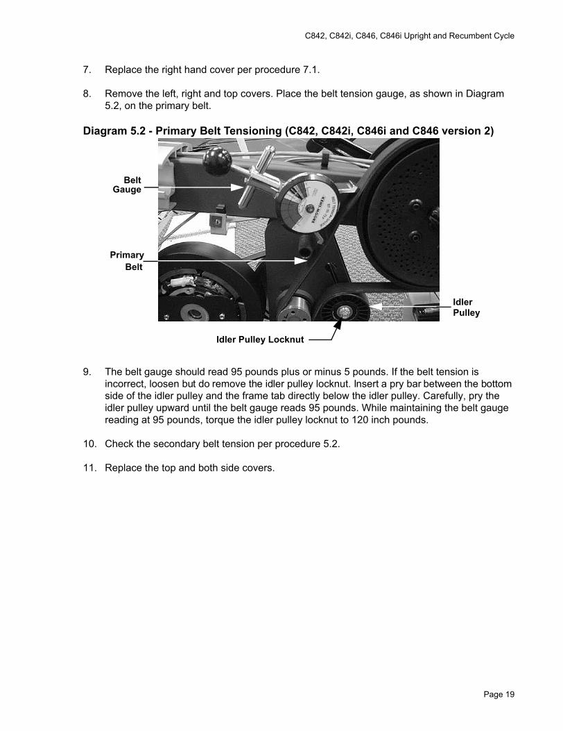
Diagram 5.2 - Primary Belt Tensioning (C842, C842i, C846i and C846 version 2)
9. The belt gauge should read 95 pounds plus or minus 5 pounds. If the belt tension is incorrect, loosen but do remove the idler pulley locknut. Insert a pry bar between the bottom side of the idler pulley and the frame tab directly below the idler pulley. Carefully, pry the idler pulley upward until the belt gauge reads 95 pounds. While maintaining the belt gauge reading at 95 pounds, torque the idler pulley locknut to 120 inch pounds.
10. Check the secondary belt tension per procedure 5.2.
11. Replace the top and both side covers.
BeltGauge
PrimaryBelt
IdlerPulley
Idler Pulley Locknut
Page 19
C842, C842i, C846, C846i Upright and Recumbent Cycle
Procedure 5.2 - Secondary Drive Belt Adjustment
1. For C842, C842i, C846i and C846 version 2 units, skip to step 8. For C846 version 1 units, continue with step 2.
2. Set the on/off switch in the “off” position.
3. Remove the left side cover per Procedure 7.1.
4. Attach a drive belt gauge (Precor part # 20030-108 or equivalent) to the upper span of the secondary drive belt. The gauge should read approximately 60 pounds. If the drive belt gauge reading is incorrect, continue with step 4.
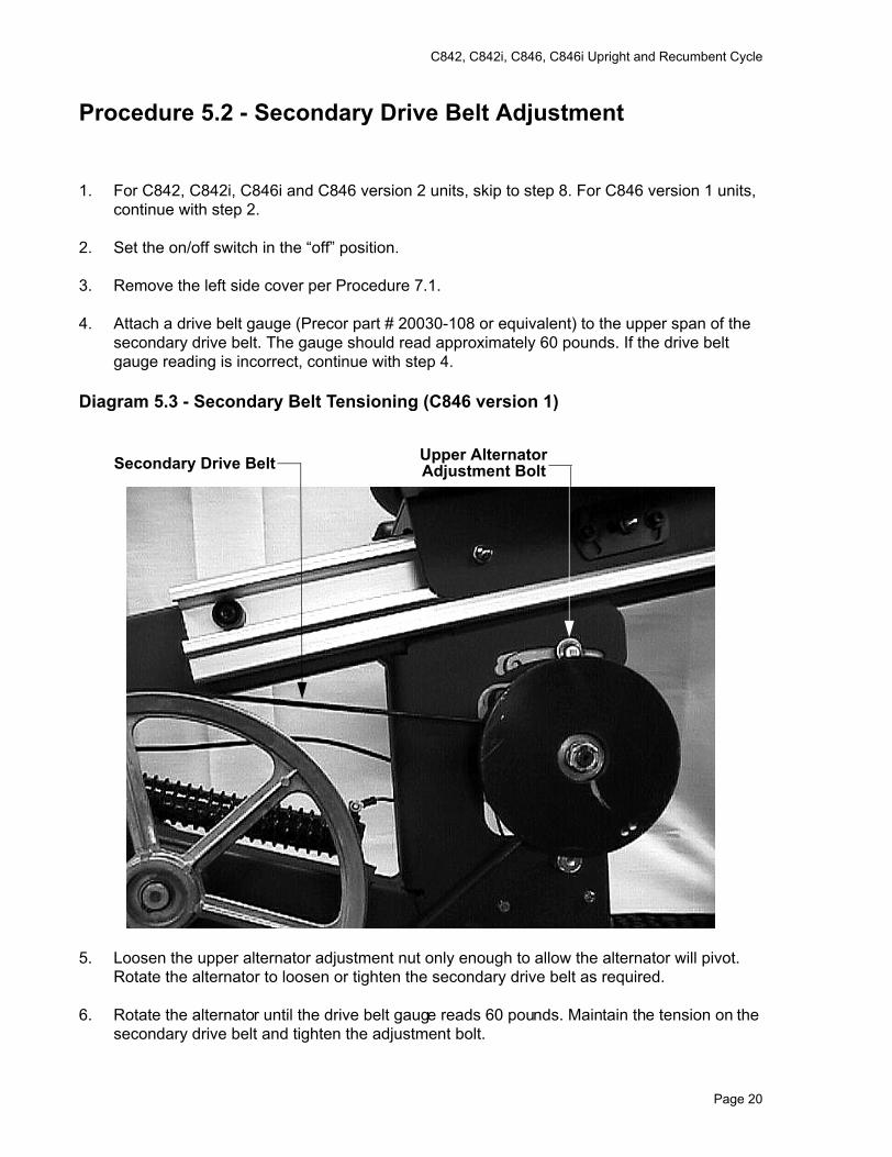
Diagram 5.3 - Secondary Belt Tensioning (C846 version 1)
5. Loosen the upper alternator adjustment nut only enough to allow the alternator will pivot. Rotate the alternator to loosen or tighten the secondary drive belt as required.
6. Rotate the alternator until the drive belt gauge reads 60 pounds. Maintain the tension on the secondary drive belt and tighten the adjustment bolt.
Secondary Drive Belt Upper AlternatorAdjustment Bolt
Page 20
C842, C842i, C846, C846i Upright and Recumbent Cycle
7. Replace the left side cover per procedure 7.1.
8. Remove both side covers and the top cover. Place the belt tension gauge, as shown in Diagram 5.4, on the secondary belt.
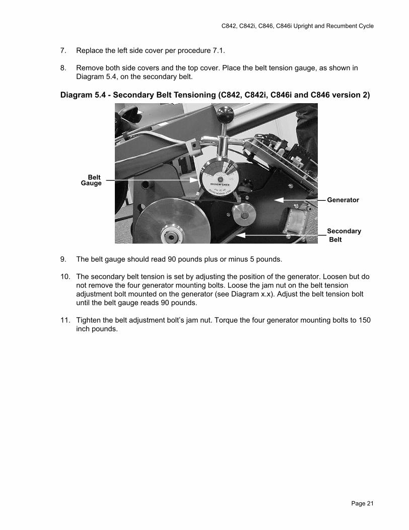
Diagram 5.4 - Secondary Belt Tensioning (C842, C842i, C846i and C846 version 2)
9. The belt gauge should read 90 pounds plus or minus 5 pounds.
10. The secondary belt tension is set by adjusting the position of the generator. Loosen but do not remove the four generator mounting bolts. Loose the jam nut on the belt tension adjustment bolt mounted on the generator (see Diagram x.x). Adjust the belt tension bolt until the belt gauge reads 90 pounds.
11. Tighten the belt adjustment bolt’s jam nut. Torque the four generator mounting bolts to 150 inch pounds.
SecondaryBelt
BeltGauge
Generator
Page 21
C842, C842i, C846, C846i Upright and Recumbent Cycle
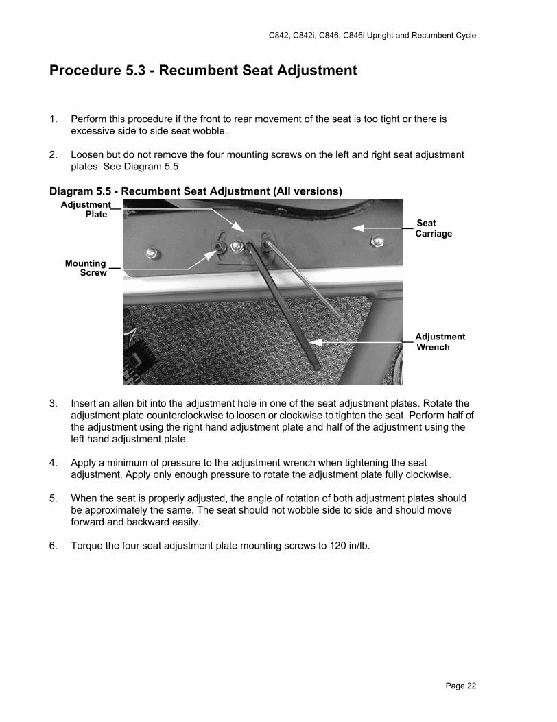
Procedure 5.3 - Recumbent Seat Adjustment
1. Perform this procedure if the front to rear movement of the seat is too tight or there is excessive side to side seat wobble.
2. Loosen but do not remove the four mounting screws on the left and right seat adjustment plates. See Diagram 5.5
Diagram 5.5 - Recumbent Seat Adjustment (All versions)
3. Insert an allen bit into the adjustment hole in one of the seat adjustment plates. Rotate the adjustment plate counterclockwise to loosen or clockwise to tighten the seat. Perform half of the adjustment using the right hand adjustment plate and half of the adjustment using the left hand adjustment plate.
4. Apply a minimum of pressure to the adjustment wrench when tightening the seat adjustment. Apply only enough pressure to rotate the adjustment plate fully clockwise.
5. When the seat is properly adjusted, the angle of rotation of both adjustment plates should be approximately the same. The seat should not wobble side to side and should move forward and backward easily.
6. Torque the four seat adjustment plate mounting screws to 120 in/lb.
AdjustmentPlate
Mounting Screw
SeatCarriage
AdjustmentWrench
Page 22
C842, C842i, C846, C846i Upright and Recumbent Cycle
Procedure 6.1 - Troubleshooting the Interconnect Cables
7. For C842, C842i, C846i and C846 version 2 units, skip to step 18. For C846 version 1 units, continue with step 2.
8. Set the on/off switch in the “off” position.
9. Both the upper and lower interconnect cable are easily disconnected at both ends. Therefore, the simplest way to troubleshoot the interconnect cables is to by-pass them with a known good interconnect cable.
10. Remove the left hand cover per Procedure 7.1.
Troubleshooting the upper interconnect cable
11. Remove the display housing per Procedure 7.13. Disconnect the upper interconnect cable from the upper PCA.
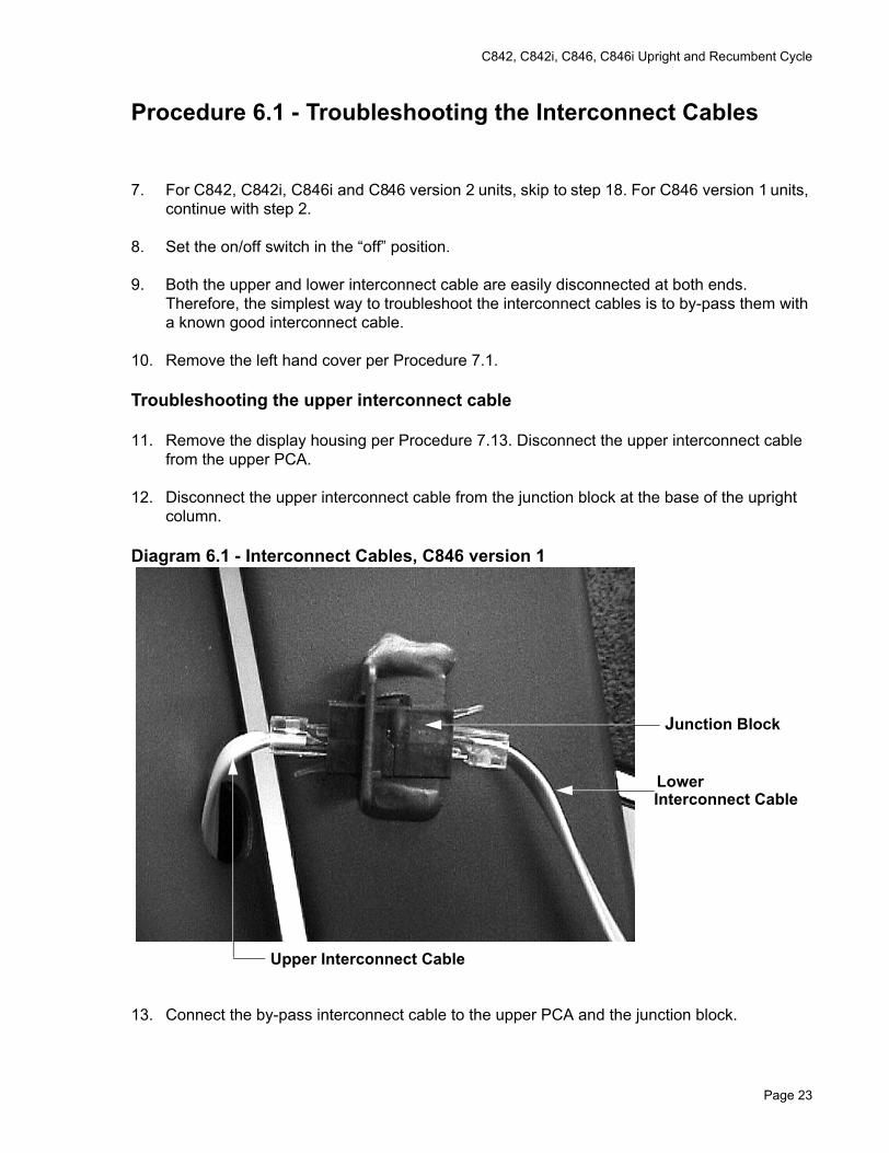
12. Disconnect the upper interconnect cable from the junction block at the base of the upright column.
Diagram 6.1 - Interconnect Cables, C846 version 1
13. Connect the by-pass interconnect cable to the upper PCA and the junction block.
Junction Block
LowerInterconnect Cable
Upper Interconnect Cable
Page 23
C842, C842i, C846, C846i Upright and Recumbent Cycle
14. Check the operation of the cycle as described in Section Four.
15. If the problem is still present re-connect the original upper interconnect cable and proceed with step 9.
Troubleshooting the Lower Interconnect cable
16. Disconnect the lower interconnect cable from the lower PCA and the junction block.
17. Connect the by-pass cable to the junction block and the lower PCA.
18. Check the operation of the cycle as described in Section Four.
19. If the problem is still present, troubleshoot junction block
Troubleshooting the Junction Block
20. Remove the display housing per Procedure 7.13. Disconnect the upper interconnect cable from the upper PCA.
21. Disconnect the lower interconnect cable from the junction block. Connect the lower interconnect cable to the upper PCA.
22. Check the operation of the cycle as described in Section Four.
23. If you have performed all of the previous tests and have not been able to locate the trouble, call Precor customer support.
24. Both the upper and lower interconnect cable are easily disconnected at both ends. Therefore, the simplest way to troubleshoot the interconnect cables is to by-pass them with a known good interconnect cable. Remove the two bolts that fasten the display column to the main bike frame. Carefully move the column away from the main bike frame. There are two cables in the column, care must be taken to avoid damaging the cables as the column is removed from the main bike frame. For conveniences, lay the column on the floor in front of the bike.
25. Remove the left hand cover per Procedure 7.1.
Troubleshooting the upper interconnect cable
26. Remove the display housing per Procedure 7.13. Disconnect the upper interconnect cable from the upper PCA.
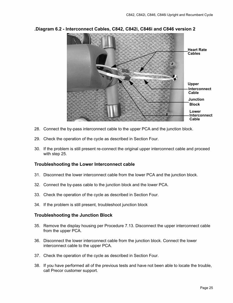
27. Disconnect the upper interconnect cable from the junction block between the column and the main frame.
Page 24
C842, C842i, C846, C846i Upright and Recumbent Cycle
.Diagram 6.2 - Interconnect Cables, C842, C842i, C846i and C846 version 2
28. Connect the by-pass interconnect cable to the upper PCA and the junction block.
29. Check the operation of the cycle as described in Section Four.
30. If the problem is still present re-connect the original upper interconnect cable and proceed with step 25.
Troubleshooting the Lower Interconnect cable
31. Disconnect the lower interconnect cable from the lower PCA and the junction block.
32. Connect the by-pass cable to the junction block and the lower PCA.
33. Check the operation of the cycle as described in Section Four.
34. If the problem is still present, troubleshoot junction block
Troubleshooting the Junction Block
35. Remove the display housing per Procedure 7.13. Disconnect the upper interconnect cable from the upper PCA.
36. Disconnect the lower interconnect cable from the junction block. Connect the lower interconnect cable to the upper PCA.
37. Check the operation of the cycle as described in Section Four.
38. If you have performed all of the previous tests and have not been able to locate the trouble, call Precor customer support.
Heart RateCables
UpperInterconnectCable
JunctionBlock
LowerInterconnectCable
Page 25
C842, C842i, C846, C846i Upright and Recumbent Cycle
Procedure 6.2 - Troubleshooting the Keypad
If the function keys on the electronic console are unresponsive, the problem may be either the upper PCA or keypad. This troubleshooting procedure gives you the information you need to determine which of these components is malfunctioning.
Procedure
1. On C846 version 1 units, set the on/off switch in the “off” position.
WARNINGBefore continuing with this procedure, review the Warning and Caution statements listed in Section One.
2. If an error 5 is being displayed, continue with step 3. If one or more keys do not function, skip to step 8.
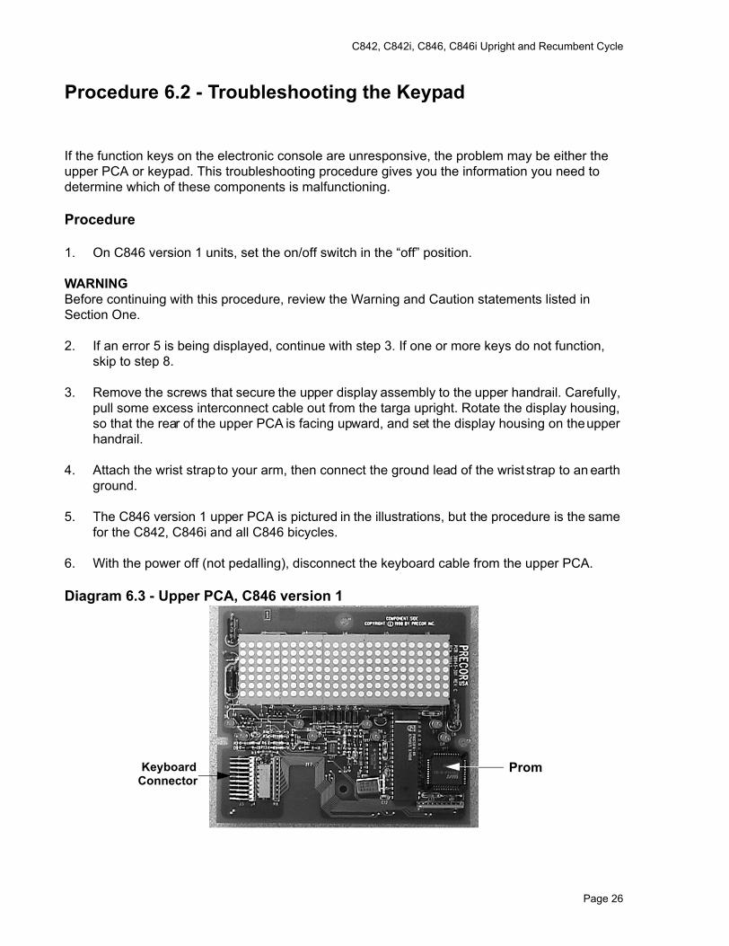
3. Remove the screws that secure the upper display assembly to the upper handrail. Carefully, pull some excess interconnect cable out from the targa upright. Rotate the display housing, so that the rear of the upper PCA is facing upward, and set the display housing on the upper handrail.
4. Attach the wrist strap to your arm, then connect the ground lead of the wrist strap to an earth ground.
5. The C846 version 1 upper PCA is pictured in the illustrations, but the procedure is the same for the C842, C846i and all C846 bicycles.
6. With the power off (not pedalling), disconnect the keyboard cable from the upper PCA.
Diagram 6.3 - Upper PCA, C846 version 1
PromKeyboardConnector
Page 26
C842, C842i, C846, C846i Upright and Recumbent Cycle
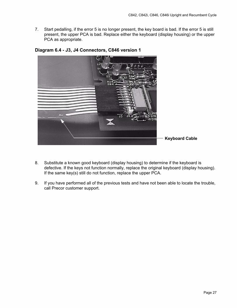
7. Start pedalling, if the error 5 is no longer present, the key board is bad. If the error 5 is still present, the upper PCA is bad. Replace either the keyboard (display housing) or the upper PCA as appropriate.
Diagram 6.4 - J3, J4 Connectors, C846 version 1
8. Substitute a known good keyboard (display housing) to determine if the keyboard is defective. If the keys not function normally, replace the original keyboard (display housing). If the same key(s) still do not function, replace the upper PCA.
9. If you have performed all of the previous tests and have not been able to locate the trouble, call Precor customer support.
Keyboard Cable
Page 27
C842, C842i, C846, C846i Upright and Recumbent Cycle
Procedure 6.3 - Display does not Illuminate
Note:In order to conserve battery power when the cycle is not in use, a time out feature is incorporated in the cycles software. If the cycle is not used (motion not detected by the speed sensor), when in the program mode, approximately 15 seconds later, the cycle will “power down” even when the on/off switch is in the “on” position.The bike will “power up” again when pedaling is resumed (motion detected by the speed sensor). In order to measure voltages in the unit it is necessary to keep the unit powered up. This can be accomplished either by pedaling on the unit or by installing the optional external power adapter.
1. On C846 Version 1 units, set the on/off switch in the on position.
2. Pedal on the cycle for a minimum of 5 seconds. If the display does not illuminate proceed with step 2 for C846 version 1 units or step 12 for C842 and C846 version 2 units and for C842i and C846i units.
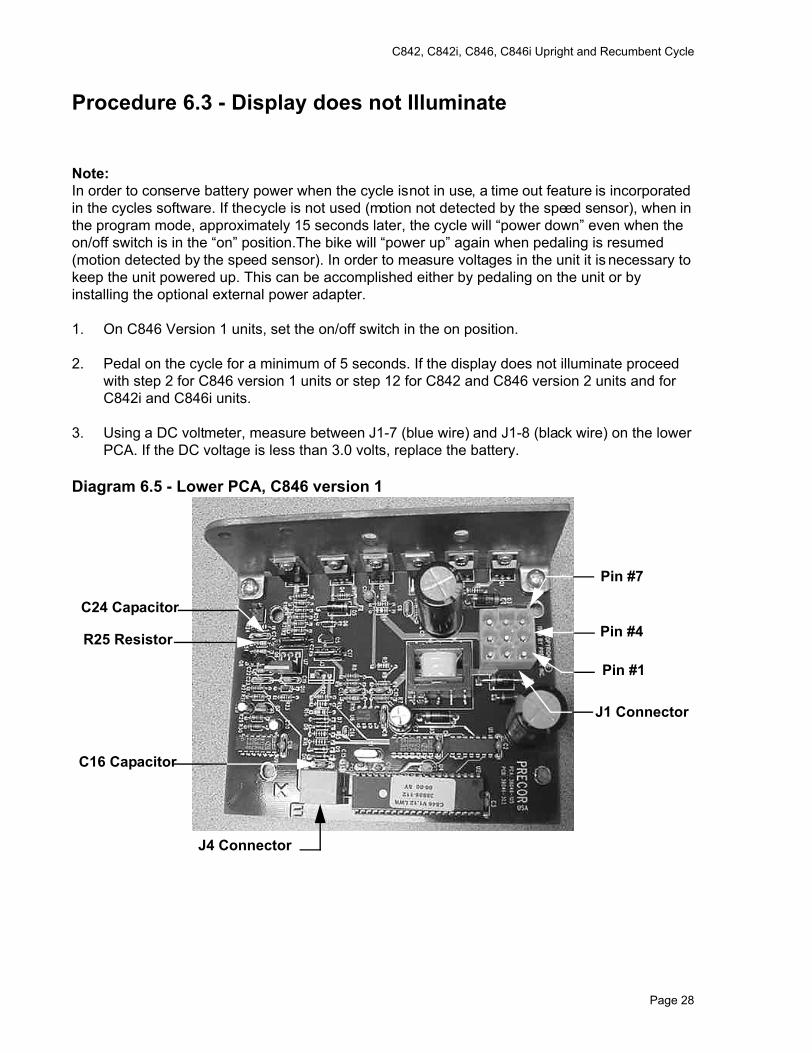
3. Using a DC voltmeter, measure between J1-7 (blue wire) and J1-8 (black wire) on the lower PCA. If the DC voltage is less than 3.0 volts, replace the battery.
Diagram 6.5 - Lower PCA, C846 version 1
J1 Connector
C16 Capacitor
J4 Connector
Pin #1
Pin #4
Pin #7
R25 Resistor
C24 Capacitor
Page 28
C842, C842i, C846, C846i Upright and Recumbent Cycle
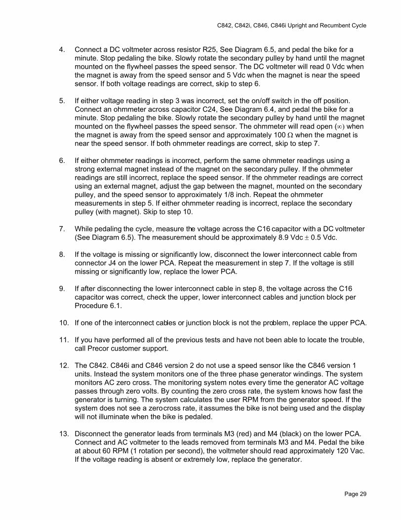
4. Connect a DC voltmeter across resistor R25, See Diagram 6.5, and pedal the bike for a minute. Stop pedaling the bike. Slowly rotate the secondary pulley by hand until the magnet mounted on the flywheel passes the speed sensor. The DC voltmeter will read 0 Vdc when the magnet is away from the speed sensor and 5 Vdc when the magnet is near the speed sensor. If both voltage readings are correct, skip to step 6.
5. If either voltage reading in step 3 was incorrect, set the on/off switch in the off position. Connect an ohmmeter across capacitor C24, See Diagram 6.4, and pedal the bike for a minute. Stop pedaling the bike. Slowly rotate the secondary pulley by hand until the magnet mounted on the flywheel passes the speed sensor. The ohmmeter will read open (∞) when the magnet is away from the speed sensor and approximately 100 Ω when the magnet is near the speed sensor. If both ohmmeter readings are correct, skip to step 7.
6. If either ohmmeter readings is incorrect, perform the same ohmmeter readings using a strong external magnet instead of the magnet on the secondary pulley. If the ohmmeter readings are still incorrect, replace the speed sensor. If the ohmmeter readings are correct using an external magnet, adjust the gap between the magnet, mounted on the secondary pulley, and the speed sensor to approximately 1/8 inch. Repeat the ohmmeter measurements in step 5. If either ohmmeter reading is incorrect, replace the secondary pulley (with magnet). Skip to step 10.
7. While pedaling the cycle, measure the voltage across the C16 capacitor with a DC voltmeter (See Diagram 6.5). The measurement should be approximately 8.9 Vdc ± 0.5 Vdc.
8. If the voltage is missing or significantly low, disconnect the lower interconnect cable from connector J4 on the lower PCA. Repeat the measurement in step 7. If the voltage is still missing or significantly low, replace the lower PCA.
9. If after disconnecting the lower interconnect cable in step 8, the voltage across the C16 capacitor was correct, check the upper, lower interconnect cables and junction block per Procedure 6.1.
10. If one of the interconnect cables or junction block is not the problem, replace the upper PCA.
11. If you have performed all of the previous tests and have not been able to locate the trouble, call Precor customer support.
12. The C842. C846i and C846 version 2 do not use a speed sensor like the C846 version 1 units. Instead the system monitors one of the three phase generator windings. The system monitors AC zero cross. The monitoring system notes every time the generator AC voltage passes through zero volts. By counting the zero cross rate, the system knows how fast the generator is turning. The system calculates the user RPM from the generator speed. If the system does not see a zero cross rate, it assumes the bike is not being used and the display will not illuminate when the bike is pedaled.
13. Disconnect the generator leads from terminals M3 (red) and M4 (black) on the lower PCA. Connect and AC voltmeter to the leads removed from terminals M3 and M4. Pedal the bike at about 60 RPM (1 rotation per second), the voltmeter should read approximately 120 Vac. If the voltage reading is absent or extremely low, replace the generator.
Page 29
C842, C842i, C846, C846i Upright and Recumbent Cycle
14. If the voltage reading in step 13 was normal, replace the lower PCA. If the lower PCA did not correct the problem, continue with step 15.
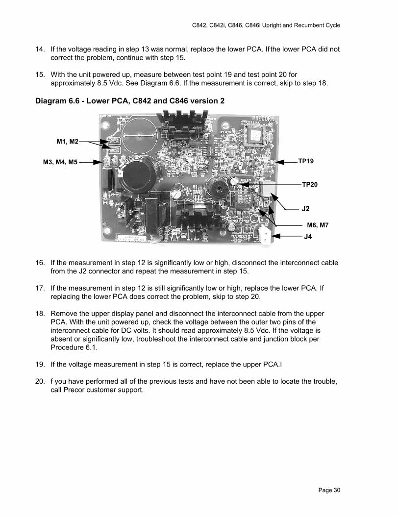
15. With the unit powered up, measure between test point 19 and test point 20 for approximately 8.5 Vdc. See Diagram 6.6. If the measurement is correct, skip to step 18.
Diagram 6.6 - Lower PCA, C842 and C846 version 2
16. If the measurement in step 12 is significantly low or high, disconnect the interconnect cable from the J2 connector and repeat the measurement in step 15.
17. If the measurement in step 12 is still significantly low or high, replace the lower PCA. If replacing the lower PCA does correct the problem, skip to step 20.
18. Remove the upper display panel and disconnect the interconnect cable from the upper PCA. With the unit powered up, check the voltage between the outer two pins of the interconnect cable for DC volts. It should read approximately 8.5 Vdc. If the voltage is absent or significantly low, troubleshoot the interconnect cable and junction block per Procedure 6.1.
19. If the voltage measurement in step 15 is correct, replace the upper PCA.I
20. f you have performed all of the previous tests and have not been able to locate the trouble, call Precor customer support.
TP19
TP20
J2
M1, M2
M3, M4, M5
M6, M7
J4
Page 30
C842, C842i, C846, C846i Upright and Recumbent Cycle
Procedure 6.4 - The RPM Display is Incorrect
1. For C842, C842i, C846i and C846 version 2 units, skip to step 8. For C846 version 1 units, continue with step 2.
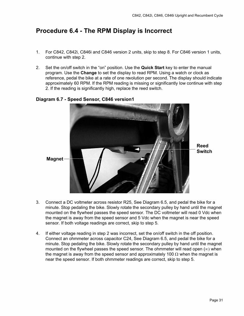
2. Set the on/off switch in the “on” position. Use the Quick Start key to enter the manual program. Use the Change to set the display to read RPM. Using a watch or clock as reference, pedal the bike at a rate of one revolution per second. The display should indicate approximately 60 RPM. If the RPM reading is missing or significantly low continue with step 2. If the reading is significantly high, replace the reed switch.
Diagram 6.7 - Speed Sensor, C846 version1
3. Connect a DC voltmeter across resistor R25, See Diagram 6.5, and pedal the bike for a minute. Stop pedaling the bike. Slowly rotate the secondary pulley by hand until the magnet mounted on the flywheel passes the speed sensor. The DC voltmeter will read 0 Vdc when the magnet is away from the speed sensor and 5 Vdc when the magnet is near the speed sensor. If both voltage readings are correct, skip to step 5.
4. If either voltage reading in step 2 was incorrect, set the on/off switch in the off position. Connect an ohmmeter across capacitor C24, See Diagram 6.5, and pedal the bike for a minute. Stop pedaling the bike. Slowly rotate the secondary pulley by hand until the magnet mounted on the flywheel passes the speed sensor. The ohmmeter will read open (∞) when the magnet is away from the speed sensor and approximately 100 Ω when the magnet is near the speed sensor. If both ohmmeter readings are correct, skip to step 5.
ReedSwitch
Magnet
Page 31
C842, C842i, C846, C846i Upright and Recumbent Cycle
5. If either ohmmeter readings is incorrect, perform the same ohmmeter readings using a strong external magnet instead of the magnet on the secondary pulley. If the ohmmeter readings are still incorrect, replace the speed sensor. If the ohmmeter readings are correct using an external magnet, adjust the gap between the magnet, mounted on the secondary pulley, and the speed sensor to approximately 1/8 inch. Repeat the ohmmeter measurements in step 3. If either ohmmeter reading is incorrect, replace the secondary pulley (with magnet). Skip to step 6.
6. Replace the lower PCA. Check the lower PCA as in step 1.
7. If you have performed all of the previous tests and have not been able to locate the trouble, call Precor customer support.
8. The C842 and C846 version 2 do not use a speed sensor like the C846 version 1 units. Instead the system monitors one of the three phase generator windings. The system monitors AC zero cross. The monitoring system notes every time the generator AC voltage passes through zero volts. By counting the zero cross rate, the system knows how fast the generator is turning. The system calculates the user RPM from the generator speed. If
9. It is highly unlikely that the RPM reading could be present but incorrect. If this condition should occur, replace the lower PCA.
Page 32
C842, C842i, C846, C846i Upright and Recumbent Cycle
Procedure 6.5 - No or Incorrect Pedaling Resistance
1. If the display is not illuminated, go to Procedure 6.3.
2. For C842, C842i, C846i and C846 version 2 units, skip to step 15. For C846 version 1 units, continue with step 3.
3. Enter the “manual” program and set the work level at “level 20”. Pedal the cycle and confirm that there is no resistance or that the resistance is abnormally low.
Note:The voltage readings in this procedure will vary with the pedaling rate. Pedal the cycle at approximately 60 RPM with the work level set at “10” while taking the voltage readings in this procedure. Resistance readings must be taken with the power off and the cycle idle.
4. Use a DC voltmeter to measure the voltage between terminals 4 (black wire) & 6 (white wire) of J1 on the lower PCA (see Diagram 6.4). The voltage should measure approximately 3.85 Vdc ± 0.5 Vdc.
5. If the voltage is missing or significantly lower than 3.85 Vdc, continue with step 6.
6. If the voltage is approximately 3.85 Vdc, but there is no resistance, measure the voltage between terminals 1 (red wire) and 4 (black wire) of the J1 connector on the lower PCA. The voltage should measure approximately 18 -19 Vdc ± 1 Vdc. Measure the voltage between terminals 1 (red wire) and 9 (yellow wire) of the J1 connector on the lower PCA. The voltage should measure approximately 2 Vdc ± 0.5 Vdc.
7. Set the on/off switch in the off position. Disconnect the J1 connector from the lower PCA. Measure between terminals 1 and 9 of the J1 connector. The ohmmeter should read approximately 1.5 Ω ± 0.5Ω. If the reading is open (∞) or significantly high replace the load resistor per Procedure 7.11.
Note:Do not reconnect the J1 connector, removed in step 6, until the resistance measurements in step 9 are completed.
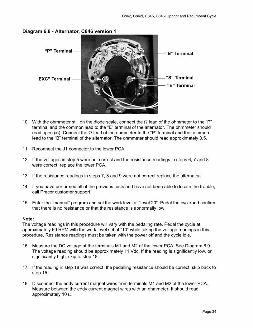
8. Measure between the “EXC” and “S” terminals on the alternator with an ohmmeter (See Diagram 6.8). The ohmmeter should read approximately 5 Ω ± 0.5Ω.
9. Set the ohmmeter on the “diode” scale. Connect the common lead of the ohmmeter to the “P” terminal and the Ω lead to the “B” terminal of the alternator. The ohmmeter should read open (∞). Connect the common lead of the ohmmeter to the “P” terminal and the Ω lead to the “E” terminal of the alternator. The ohmmeter should read approximately 0.5.
Page 33
C842, C842i, C846, C846i Upright and Recumbent Cycle
Diagram 6.8 - Alternator, C846 version 1
10. With the ohmmeter still on the diode scale, connect the Ω lead of the ohmmeter to the “P” terminal and the common lead to the “E” terminal of the alternator. The ohmmeter should read open (∞). Connect the Ω lead of the ohmmeter to the “P” terminal and the common lead to the “B” terminal of the alternator. The ohmmeter should read approximately 0.5.
11. Reconnect the J1 connector.to the lower PCA
12. If the voltages in step 5 were not correct and the resistance readings in steps 6, 7 and 8 were correct, replace the lower PCA.
13. If the resistance readings in steps 7, 8 and 9 were not correct replace the alternator.
14. If you have performed all of the previous tests and have not been able to locate the trouble, call Precor customer support.
15. Enter the “manual” program and set the work level at “level 20”. Pedal the cycle and confirm that there is no resistance or that the resistance is abnormally low.
Note:The voltage readings in this procedure will vary with the pedaling rate. Pedal the cycle at approximately 60 RPM with the work level set at “10” while taking the voltage readings in this procedure. Resistance readings must be taken with the power off and the cycle idle.
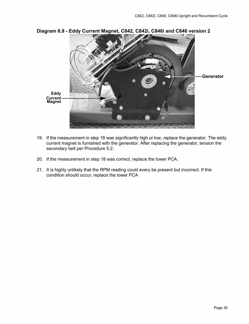
16. Measure the DC voltage at the terminals M1 and M2 of the lower PCA. See Diagram 6.9. The voltage reading should be approximately 11 Vdc. If the reading is significantly low, or significantly high, skip to step 18.
17. If the reading in step 18 was correct, the pedalling resistance should be correct, skip back to step 15.
18. Disconnect the eddy current magnet wires from terminals M1 and M2 of the lower PCA. Measure between the eddy current magnet wires with an ohmmeter. It should read approximately 10 Ω.
“B” Terminal
“S” Terminal“EXC” Terminal
“P” Terminal
“E” Terminal
Page 34
C842, C842i, C846, C846i Upright and Recumbent Cycle
Diagram 6.9 - Eddy Current Magnet, C842, C842i, C846i and C846 version 2
19. If the measurement in step 18 was significantly high or low, replace the generator. The eddy current magnet is furnished with the generator. After replacing the generator, tension the secondary belt per Procedure 5.2.
20. If the measurement in step 18 was correct, replace the lower PCA.
21. It is highly unlikely that the RPM reading could every be present but incorrect. If this condition should occur, replace the lower PCA
EddyCurrentMagnet
Generator
Page 35
C842, C842i, C846, C846i Upright and Recumbent Cycle
Procedure 6.6 - Unit does not Mechanically Operate Freely/Quietly
1. On C846 version 1 units, set the on/off switch in the off position.
2. Remove both covers per Procedure 7.1, steps 2-7.
3. If the unit is noisy, skip to step 8. If the unit does not turn freely continue with step 4.
4. Remove the primary drive belt per Procedure 7.15.
5. Remove the secondary drive belt per procedure 7.16.
6. Turn the primary pulley, secondary pulley, idler pulley and alternator or generator by hand to determine which part is not turning freely.
7. Replace the necessary part(s) by following the appropriate procedure in Section Seven.
8. Operate the unit and listen to the noise generated. The noise will be produced by one of the following parts: primary pulley bearings, secondary pulley bearings, idler pulley, generator or alternator.
9. Replace the necessary part(s) by following the appropriate procedure in Section Seven.
Page 36
C842, C842i, C846, C846i Upright and Recumbent Cycle
Procedure 6.7 - Troubleshooting Hand Held Heart Rate
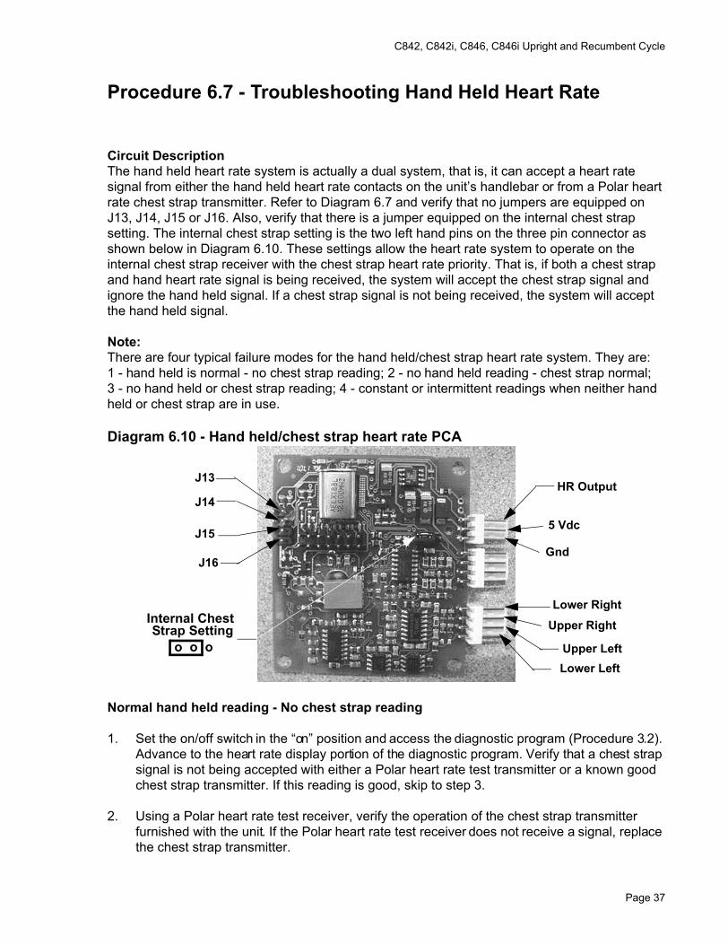
Circuit DescriptionThe hand held heart rate system is actually a dual system, that is, it can accept a heart rate signal from either the hand held heart rate contacts on the unit’s handlebar or from a Polar heart rate chest strap transmitter. Refer to Diagram 6.7 and verify that no jumpers are equipped on J13, J14, J15 or J16. Also, verify that there is a jumper equipped on the internal chest strap setting. The internal chest strap setting is the two left hand pins on the three pin connector as shown below in Diagram 6.10. These settings allow the heart rate system to operate on the internal chest strap receiver with the chest strap heart rate priority. That is, if both a chest strap and hand heart rate signal is being received, the system will accept the chest strap signal and ignore the hand held signal. If a chest strap signal is not being received, the system will accept the hand held signal.
Note:There are four typical failure modes for the hand held/chest strap heart rate system. They are: 1 - hand held is normal - no chest strap reading; 2 - no hand held reading - chest strap normal; 3 - no hand held or chest strap reading; 4 - constant or intermittent readings when neither hand held or chest strap are in use.
Diagram 6.10 - Hand held/chest strap heart rate PCA
Normal hand held reading - No chest strap reading
1. Set the on/off switch in the “on” position and access the diagnostic program (Procedure 3.2). Advance to the heart rate display portion of the diagnostic program. Verify that a chest strap signal is not being accepted with either a Polar heart rate test transmitter or a known good chest strap transmitter. If this reading is good, skip to step 3.
2. Using a Polar heart rate test receiver, verify the operation of the chest strap transmitter furnished with the unit. If the Polar heart rate test receiver does not receive a signal, replace the chest strap transmitter.
J13
J14
J15
J16
5 Vdc
Gnd
Lower Right
Upper Right
Upper LeftLower Left
HR Output
o o o
Internal ChestStrap Setting
Page 37
C842, C842i, C846, C846i Upright and Recumbent Cycle
3. Set the on/off switch in the “off” position and remove the display housing.
4. Verify the internal chest strap setting is set as shown in Diagram 6.7. Verify that a ferrite bead is installed on the heart rate PCA to upper PCA cable.
5. If the above procedures did not correct the problem, replace the heart rate PCA.
No hand held reading - Normal chest strap reading
6. Set the on/off switch in the “on” position and access the diagnostic program (Procedure 3.2). Advance to the heart rate display portion of the diagnostic program. Verify that a hand held signal is not being accepted by firmly grasping both the right and left hand held contacts on the handlebars. Cover as much of the contact surface area with your hands as possible (without moving your hands), you should receive a heart rate reading within ten seconds.
7. If a hand held signal is not being accepted, set the on/off switch in the off position.
8. Temporarily, install a spare jumper on J14 of the heart rate PCA (hand held priority). Set the on/off switch in the “on” position and repeat the procedure in step 6.
9. If the hand held signal is now being accept, something in the near vicinity is radiating RF (radio frequency) energy that is being received by the chest strap portion of the heart rate PCA. Disabling the chest strap signal proves that it is radiated energy that is causing the problem.
10. If a hand held signal still not being accepted, skip to step 13.
11. The source of the radiated energy must be determined and relocated so that it no longer affects the heart rate PCA. Televisions, cell phones, Cardio-theatre receivers, etc. are possible sources of radiated energy.
12. Set the on/off switch in the “off” position, and remove the temporary jumper from J14 of the heart rate PCA. Re-locate all potential sources of radiation. Set the on/off switch in the “on” position and repeat the procedure in step 6.
13. Set the on/off switch in the “on” position and access the diagnostic program (Procedure 3.2). Advance to the heart rate display portion of the diagnostic program. Verify that a hand held signal is not being accepted by firmly grasping both the right and left hand held contacts with the opposite hands, right hand on the left handlebar contacts and left hand on the right handlebar contacts. Cover as much of the contact surface area with your hands as possible, you should receive a heart rate reading within ten seconds. If a hand held signal is still not being accepted, skip to step 15.
14. If a hand held signal was accepted in step 13, the hand held contact wiring is reversed. The end of the wire harness that connects to the hand held contacts in the handlebar is segregated into two groups. One group has blue shrink wrap around it and the other group has black shrink wrap around it. The “blue” group must go to the right hand contacts and the “black” group must go to the left hand contacts. In both groups the black wire must go to the lower contact and the red wire must go to the upper contact. If necessary, rewire the hand held contacts as described above and test as described in step 6.
Page 38
C842, C842i, C846, C846i Upright and Recumbent Cycle
15. Set the on/off switch in the “off” position. Refer to Diagram 6.7 for the following measurements. With an ohmmeter measure between the “lower right contact” pin on the J1 connector and the lower right hand held heart rate contact on the handlebar. The reading should be 1 Ω or less. Measure between the “upper right contact” pin on the J1 connector and the upper right hand held heart rate contact on the handlebar. The reading should be 1 Ω or less. Measure between the “upper left contact” pin on the J1 connector and the upper left hand held heart rate contact on the handlebar. The reading should be 1 Ω or less. Measure between the “lower left contact” pin on the J1 connector and the lower left hand held heart rate contact on the handlebar. The reading should be 1 Ω or less. If any of the above readings are greater than 1 Ω, replace the heart rate PCA to handlebar wire harness.
No hand held reading - No chest strap reading
16. Set the on/off switch in the “on” position and access the diagnostic program (Procedure 3.2). Advance to the heart rate display portion of the diagnostic program. Verify that neither a chest strap signal or a hand held signal is being accepted with either a heart rate test transmitter or a chest strap transmitter.
17. Check the plug/connector connections on both the heart rate PCA (J4), and upper PCA (J1).
18. If neither a chest strap signal or a hand held signal is being accepted, measure between the “ground” and “5 Vdc” pins on J4 for 5 Vdc. If 5 Vdc is present, replace the heart rate PCA.
19. If 5 Vdc is not present, remove the connector from J4 of the heart rate PCA. Measure between the “ground” and “5 Vdc” pins of the connector (just removed from the heart rate PCA) for 5 Vdc. If 5 Vdc is present, replace the heart rate PCA. If the 5 Vdc is not present, measure between the corresponding pins of J1 on the upper PCA (red and black wires). If 5 Vdc is not present replace the upper PCA. If 5 Vdc is present, replace the upper PCA to heart rate PCA cable.
Constant or intermittent readings when neither the hand held or chest strap is in use
20. Verify that a ferrite core is clamped around the heart rate PCA to upper PCA cable.
21. Constant or intermittent heart rate readings when neither heart rate system is in use is caused by something in the near vicinity radiating RF energy that is being received by the chest strap portion of the heart rate PCA.
22. Temporarily, install a spare jumper on J14 of the heart rate PCA (hand held priority). Set the on/off switch in the “on” position and repeat the procedure in step 6.
23. If the hand held signal is now being accept, something in the near vicinity is radiating RF energy that is being received by the chest strap portion of the heart rate PCA. Disabling the chest strap signal proves that it is radiated energy that is causing the problem.
24. The source of the radiated energy must be determined and relocated so that it no longer affects the heart rate PCA. Televisions, cell phones, Cardio-theatre receivers, etc. are possible sources of radiated energy.
Page 39
C842, C842i, C846, C846i Upright and Recumbent Cycle
25. Set the on/off switch in the “off” position, and remove the spare jumper from J14 of the heart rate PCA. Re-locate all potential sources of radiation. Set the on/off switch in the “on” position and repeat the procedure in step 6.
Page 40
C842, C842i, C846, C846i Upright and Recumbent Cycle
Procedure 7.1 - Removing or Replacing One or Both Covers
1. For C842, C842i, C846i and C846 version 2 units, skip to step 14. For C846 version 1 units, continue with step 2.
2. Set the on/off switch in the off position.
3. The right hand cover may be removed without removing the right hand crankarm. The left hand crankarm must be removed to remove the left hand cover.
4. If you are removing the left hand cover, a plastic cap covers the crankarm mounting bolt. Using a thin bladed tool, remove the cap from the crankarm. (See Diagram 7.1), continue with step 4. If you are removing the right hand cover skip with step 6.
5. Grasp and hold the left hand crankarm, loosen but do not remove the crankarm mounting bolt with a socket wrench.
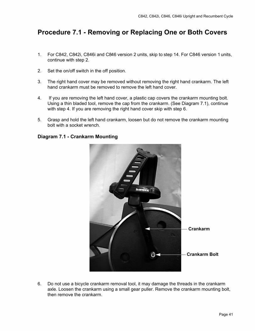
Diagram 7.1 - Crankarm Mounting
6. Do not use a bicycle crankarm removal tool, it may damage the threads in the crankarm axle. Loosen the crankarm using a small gear puller. Remove the crankarm mounting bolt, then remove the crankarm.
Crankarm
Crankarm Bolt
Page 41
C842, C842i, C846, C846i Upright and Recumbent Cycle
7. Remove the cover fasteners across the top surface of the covers. Remove the fasteners from across the bottom edge of the cover(s) being removed.
8. Remove the column mounting bolts associated with the cover(s) being removed (2 per cover). Remove the cover(s).
Caution:If both covers were removed in step 7, replace the column mounting bolts after the covers have been removed. If the column mounting bolts are not replaced the column will be unsupported and may fall off of it’s mount.
9. When maintenance procedures are complete, remove the column mounting bolts (if necessary). Set the original or replacement cover(s) in place on the cycle’s frame.
10. Replace and hand tighten the column mounting bolts.
11. Hand start all of the fasteners across the top surface and bottom edge(s) of the cover(s). Tighten all of the cover fasteners and column bolts in the following order: the three screws across the top of the cover, the two screws on the rear of the cover, the two screws on the bottom of the cover and the column mounting bolts last.
12. If the left hand cover has been removed, align the flat surfaces of the crankarm with the flat surfaces of the axle and slide the crankarm onto the axle. Ensure that the crankarms are opposite (180°) each other. Place blue loctite on the crankarm mounting bolt and thread the crankarm mounting bolt into the axle and torque the crankarm bolt to 500 in. lbs. Press the crankarm cap into place in the crankarm(s).
13. Operate the cycle a high resistance setting until you are assured that the crankarms are securely mounted.
14. Remove four screws from the and left side of the top cover.
NoteIt is not necessary to remove the crankarms to remove the covers on the C842 and C846 version 2 units.
15. Remove two screws from the rear of the cover and two screws from the bottom of the left and right covers. Remove the left and right cover. Grasp the top cover and move it sideways away from the front column. Slide the top cover forward and off.
16. When maintenance procedures are complete, set the top cover in place. Gently spread the the two projecting legs at the rear of the cover and slide the legs under the seat rail. Take care that you do not snag the lower PCA wiring with the top cover legs.
17. Hand start the two front bolts third from the front top cover mounting bolts on both sides of the cover. Only start them a few threads, just enough so that they are securely in place.
18. Slide the top edge of the right side cover under the top cover and hand start the two remaining top bolts and the two bottom bolts.
Page 42

C842, C842i, C846, C846i Upright and Recumbent Cycle
19. Slide the top edge of the left side cover under the top cover and hand start the two remaining top bolts and the two bottom bolts. Hand start the two rear cover bolts.
20. Securely tighten all fourteen cover bolts.
Page 43
C842, C842i, C846, C846i Upright and Recumbent Cycle
Procedure 7.2 - Replacing a Pedal or Crankarm
1. For C842, C842i, C846i and C846 version 2 units, skip to step 10. For C846 version 1 units, continue with step 2.
2. Set the on/off switch in the off position.
3. If you are replacing a pedal(s) only it is not necessary to remove the crankarm(s).
4. Grasp the pedal spindle with an open end wrench where it threads into the crankarm. The right hand pedal has normal threads and the left hand pedal has reverse threads. The Left hand pedal must be turned clockwise to loosen and counter-clockwise to tighten.Un-thread the pedal(s) from the crankarms.
5. If you are not replacing crankarms skip to step 7. Otherwise continue with step 5.
6. Remove the crankarm(s) per Procedure 7.1, steps 2-4.
7. Replace the crankarm(s) per Procedure 7.1, steps 11-13.
8. Hand thread the pedal(s) into the crankarm(s). Remember, the left hand pedal is reverse threaded.
9. Torque the pedal(s) to 150 in/lb. This procedure is complete.
10. If you are replacing a pedal(s) only it is not necessary to remove the crankarm(s).
11. Grasp the pedal spindle with an open end wrench where it threads into the crankarm. The right hand pedal has normal threads and the left hand pedal has reverse threads. The Left hand pedal must be turned clockwise to loosen and counter-clockwise to tighten. Un-thread the pedal(s) from the crankarms.
12. If you are not replacing crankarms skip to step 17. Otherwise continue with step 13.
13. Remove crankarm locking bolt with a 6 mm allen wrench and the crankarm mounting bolt with a 8 mm allen wrench. See Diagram 7.2.
14. Set the replacement crankarm on the crankarm axle. Ensure that the crankarm alignment pin engages in its mating hole in the primary pulley.
15. Hand start the crankarm mounting bolt and locking bolt. First torque the crankarm mounting bolt to 245 inch pounds. Then torque the crankarm locking bolt to 325 inch pounds.
16. Replace the remaining crankarm, if necessary in the same manner as in steps 13-15.
Page 44

C842, C842i, C846, C846i Upright and Recumbent Cycle
Diagram 7.2 - Crankarm, C842, C842i, C846i and C846 version 2
17. Hand thread the pedal(s) into the crankarm(s). Remember, the left hand pedal is reverse threaded.
18. Torque the pedal(s) to 150 in/lb.
MountingBolt
LockingBolt
Page 45
C842, C842i, C846, C846i Upright and Recumbent Cycle
Procedure 7.3 - Replacing the Seat or Seat Post (Upright Cycle)
1. On C846 version 1 units, set the on/off switch in the off position.
2. Loosen the seat mounting nut with a box or open end wrench. Lift the seat upward and off of the seat post. If you are not replacing the seat post, skip to step 5.
3. Pull outward on the seat adjustment knob and lift the seat post out of the cycle’s frame.
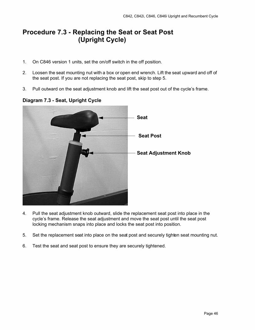
Diagram 7.3 - Seat, Upright Cycle
4. Pull the seat adjustment knob outward, slide the replacement seat post into place in the cycle’s frame. Release the seat adjustment and move the seat post until the seat post locking mechanism snaps into place and locks the seat post into position.
5. Set the replacement seat into place on the seat post and securely tighten seat mounting nut.
6. Test the seat and seat post to ensure they are securely tightened.
Seat
Seat Post
Seat Adjustment Knob
Page 46
C842, C842i, C846, C846i Upright and Recumbent Cycle
Procedure 7.4 - Replacing All or Part of a Seat Carriage Assembly (Recumbent Cycle)
Note:The seat carriage assembly was modified on April 1, 2000. If you have a unit manufactured prior to April 1, 2000 and are experiencing a problem with the seat rocking, it is recommended that the seat carriage be upgraded by installing a 58012-101 seat carriage upgrade kit. The seat carriage and seat carriage parts described in this procedure refer to the seat carriage assembly manufactured starting April 1, 2000.
1. For C842, C846i and C846 version 2 units, skip to step 15. For C846 version 1 units, continue with step 2.
2. Set the on/off switch in the off position.
3. The seat carriage assembly consists of the following: carriage, seat, wheels and seat adjustment assembly (See Diagram 7.4).
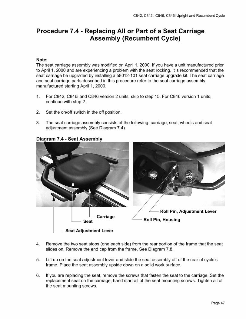
Diagram 7.4 - Seat Assembly
4. Remove the two seat stops (one each side) from the rear portion of the frame that the seat slides on. Remove the end cap from the frame. See Diagram 7.8.
5. Lift up on the seat adjustment lever and slide the seat assembly off of the rear of cycle’s frame. Place the seat assembly upside down on a solid work surface.
6. If you are replacing the seat, remove the screws that fasten the seat to the carriage. Set the replacement seat on the carriage, hand start all of the seat mounting screws. Tighten all of the seat mounting screws.
CarriageSeat
Seat Adjustment Lever
Roll Pin, Adjustment Lever
Roll Pin, Housing
Page 47
C842, C842i, C846, C846i Upright and Recumbent Cycle
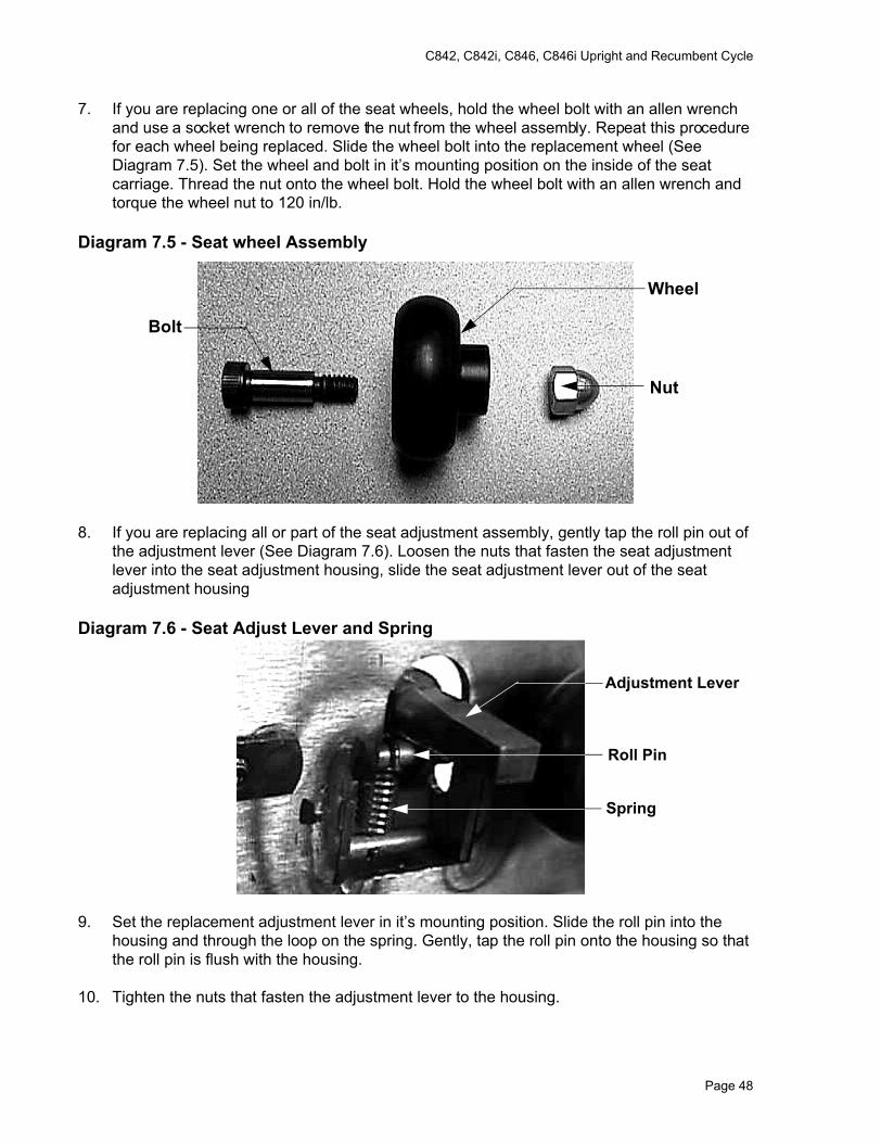
7. If you are replacing one or all of the seat wheels, hold the wheel bolt with an allen wrench and use a socket wrench to remove the nut from the wheel assembly. Repeat this procedure for each wheel being replaced. Slide the wheel bolt into the replacement wheel (See Diagram 7.5). Set the wheel and bolt in it’s mounting position on the inside of the seat carriage. Thread the nut onto the wheel bolt. Hold the wheel bolt with an allen wrench and torque the wheel nut to 120 in/lb.
Diagram 7.5 - Seat wheel Assembly
8. If you are replacing all or part of the seat adjustment assembly, gently tap the roll pin out of the adjustment lever (See Diagram 7.6). Loosen the nuts that fasten the seat adjustment lever into the seat adjustment housing, slide the seat adjustment lever out of the seat adjustment housing
Diagram 7.6 - Seat Adjust Lever and Spring
9. Set the replacement adjustment lever in it’s mounting position. Slide the roll pin into the housing and through the loop on the spring. Gently, tap the roll pin onto the housing so that the roll pin is flush with the housing.
10. Tighten the nuts that fasten the adjustment lever to the housing.
Wheel
Bolt
Nut
Adjustment Lever
Roll Pin
Spring
Page 48
C842, C842i, C846, C846i Upright and Recumbent Cycle
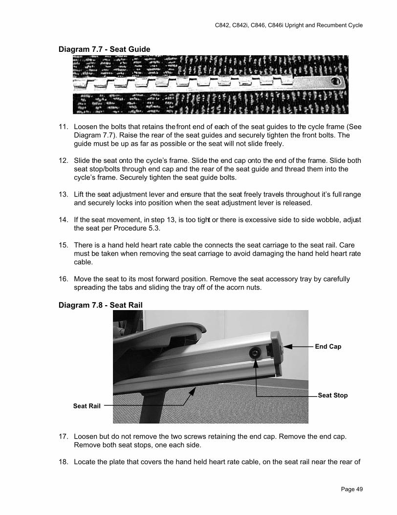
Diagram 7.7 - Seat Guide
11. Loosen the bolts that retains the front end of each of the seat guides to the cycle frame (See Diagram 7.7). Raise the rear of the seat guides and securely tighten the front bolts. The guide must be up as far as possible or the seat will not slide freely.
12. Slide the seat onto the cycle’s frame. Slide the end cap onto the end of the frame. Slide both seat stop/bolts through end cap and the rear of the seat guide and thread them into the cycle’s frame. Securely tighten the seat guide bolts.
13. Lift the seat adjustment lever and ensure that the seat freely travels throughout it’s full range and securely locks into position when the seat adjustment lever is released.
14. If the seat movement, in step 13, is too tight or there is excessive side to side wobble, adjust the seat per Procedure 5.3.
15. There is a hand held heart rate cable the connects the seat carriage to the seat rail. Care must be taken when removing the seat carriage to avoid damaging the hand held heart rate cable.
16. Move the seat to its most forward position. Remove the seat accessory tray by carefully spreading the tabs and sliding the tray off of the acorn nuts.
Diagram 7.8 - Seat Rail
17. Loosen but do not remove the two screws retaining the end cap. Remove the end cap. Remove both seat stops, one each side.
18. Locate the plate that covers the hand held heart rate cable, on the seat rail near the rear of
End Cap
Seat StopSeat Rail
Page 49
C842, C842i, C846, C846i Upright and Recumbent Cycle
the seat. Remove the plate. The cable may be stuck to the plate with double sided tape.
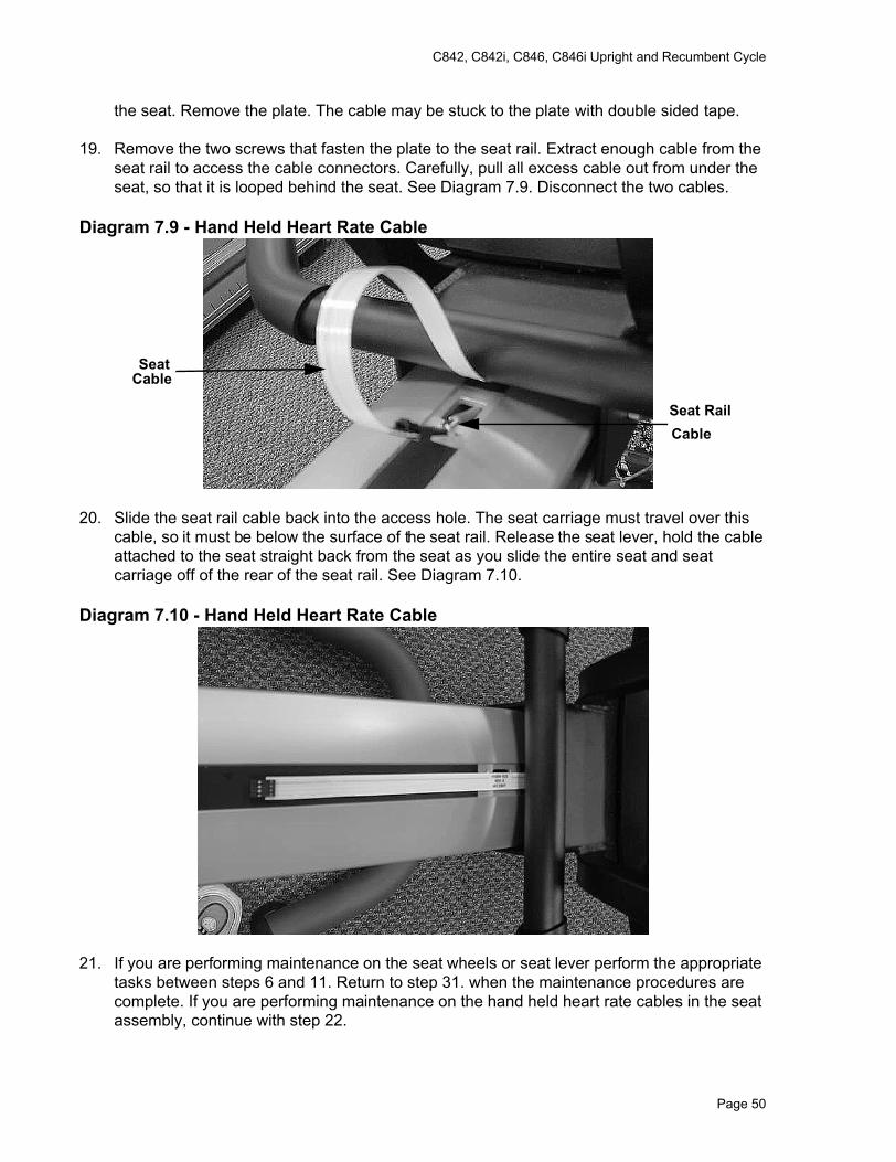
19. Remove the two screws that fasten the plate to the seat rail. Extract enough cable from the seat rail to access the cable connectors. Carefully, pull all excess cable out from under the seat, so that it is looped behind the seat. See Diagram 7.9. Disconnect the two cables.
Diagram 7.9 - Hand Held Heart Rate Cable
20. Slide the seat rail cable back into the access hole. The seat carriage must travel over this cable, so it must be below the surface of the seat rail. Release the seat lever, hold the cable attached to the seat straight back from the seat as you slide the entire seat and seat carriage off of the rear of the seat rail. See Diagram 7.10.
Diagram 7.10 - Hand Held Heart Rate Cable
21. If you are performing maintenance on the seat wheels or seat lever perform the appropriate tasks between steps 6 and 11. Return to step 31. when the maintenance procedures are complete. If you are performing maintenance on the hand held heart rate cables in the seat assembly, continue with step 22.
Seat RailCable
SeatCable
Page 50
C842, C842i, C846, C846i Upright and Recumbent Cycle
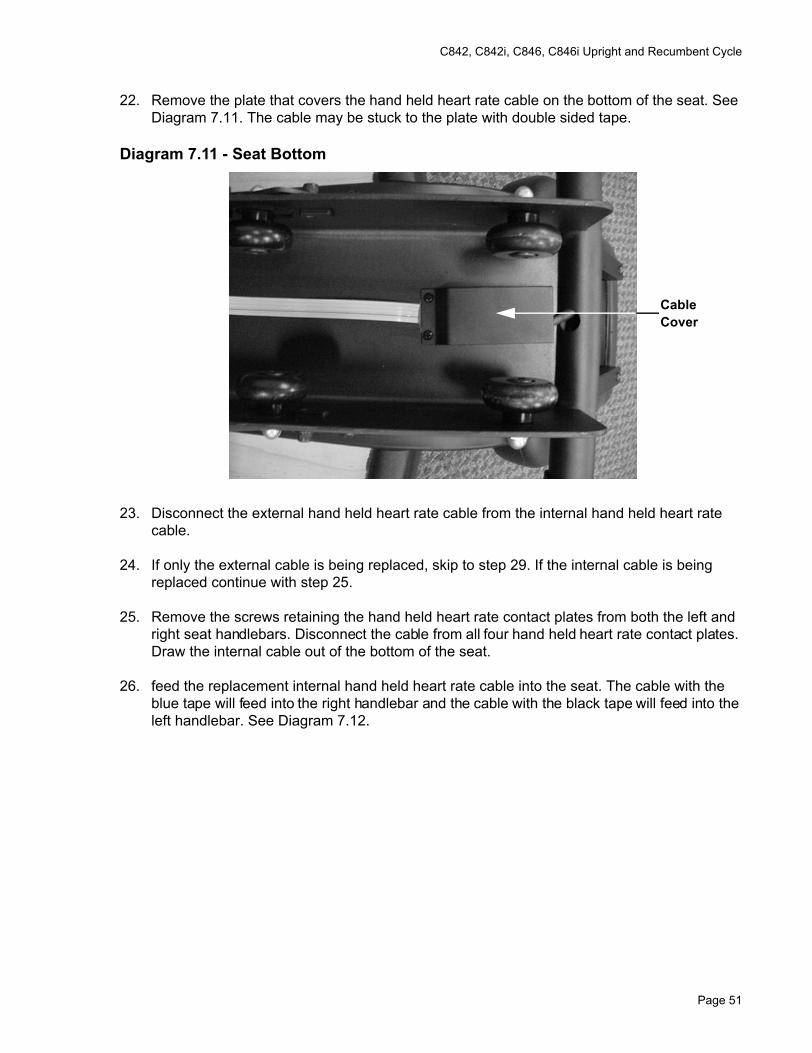
22. Remove the plate that covers the hand held heart rate cable on the bottom of the seat. See Diagram 7.11. The cable may be stuck to the plate with double sided tape.
Diagram 7.11 - Seat Bottom
23. Disconnect the external hand held heart rate cable from the internal hand held heart rate cable.
24. If only the external cable is being replaced, skip to step 29. If the internal cable is being replaced continue with step 25.
25. Remove the screws retaining the hand held heart rate contact plates from both the left and right seat handlebars. Disconnect the cable from all four hand held heart rate contact plates. Draw the internal cable out of the bottom of the seat.
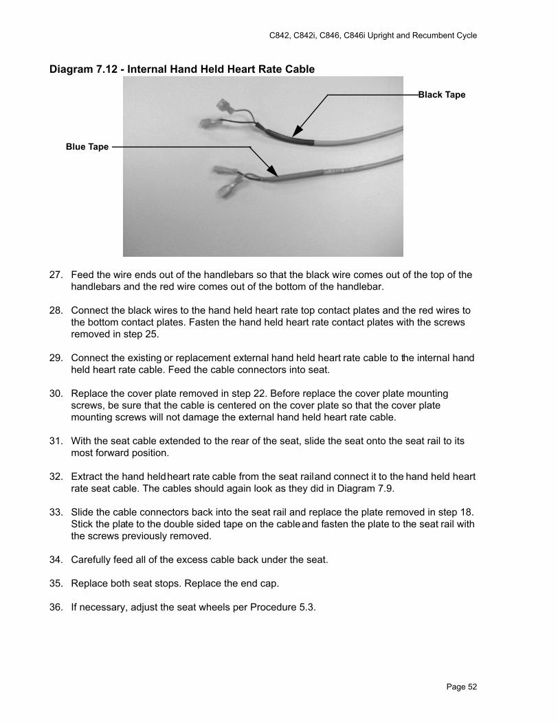
26. feed the replacement internal hand held heart rate cable into the seat. The cable with the blue tape will feed into the right handlebar and the cable with the black tape will feed into the left handlebar. See Diagram 7.12.
CableCover
Page 51
C842, C842i, C846, C846i Upright and Recumbent Cycle
Diagram 7.12 - Internal Hand Held Heart Rate Cable
27. Feed the wire ends out of the handlebars so that the black wire comes out of the top of the handlebars and the red wire comes out of the bottom of the handlebar.
28. Connect the black wires to the hand held heart rate top contact plates and the red wires to the bottom contact plates. Fasten the hand held heart rate contact plates with the screws removed in step 25.
29. Connect the existing or replacement external hand held heart rate cable to the internal hand held heart rate cable. Feed the cable connectors into seat.
30. Replace the cover plate removed in step 22. Before replace the cover plate mounting screws, be sure that the cable is centered on the cover plate so that the cover plate mounting screws will not damage the external hand held heart rate cable.
31. With the seat cable extended to the rear of the seat, slide the seat onto the seat rail to its most forward position.
32. Extract the hand held heart rate cable from the seat rail and connect it to the hand held heart rate seat cable. The cables should again look as they did in Diagram 7.9.
33. Slide the cable connectors back into the seat rail and replace the plate removed in step 18. Stick the plate to the double sided tape on the cable and fasten the plate to the seat rail with the screws previously removed.
34. Carefully feed all of the excess cable back under the seat.
35. Replace both seat stops. Replace the end cap.
36. If necessary, adjust the seat wheels per Procedure 5.3.
Black Tape
Blue Tape
Page 52
C842, C842i, C846, C846i Upright and Recumbent Cycle
Procedure 7.5 - Replacing the Column
1. For C842, C846i and C846 version 2 units, skip to step 14. For C846 version 1 units, continue with step 2.
2. Set the on/off switch in the off position.
3. Remove the left hand cover per Procedure 7.1.
4. Remove the display housing per Procedure 7.12, steps 1-4.
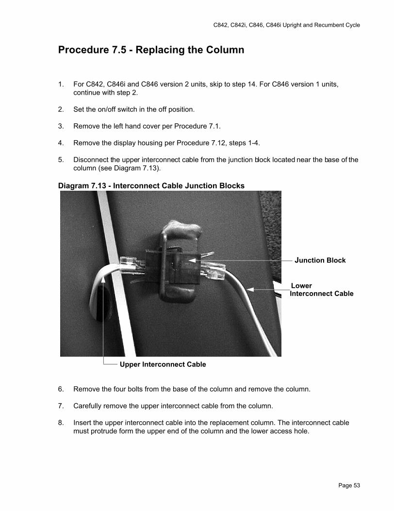
5. Disconnect the upper interconnect cable from the junction block located near the base of the column (see Diagram 7.13).
Diagram 7.13 - Interconnect Cable Junction Blocks
6. Remove the four bolts from the base of the column and remove the column.
7. Carefully remove the upper interconnect cable from the column.
8. Insert the upper interconnect cable into the replacement column. The interconnect cable must protrude form the upper end of the column and the lower access hole.
Junction Block
LowerInterconnect Cable
Upper Interconnect Cable
Page 53
C842, C842i, C846, C846i Upright and Recumbent Cycle
9. Set the column at it’s mounting position and hand start all four column mounting bolts. Securely tighten the column mounting bolts. Ensure that the column is securely fastened and does not wiggle or move.
10. Reconnect the upper interconnect cable to the junction block.
11. Reconnect the interconnect cable to the J1 connector on the upper PCA.
12. Set the display housing at it’s mounting position on the display backing plate. Replace and tighten display housing mounting screws.
13. Replace the cover per Procedure 7.1.
14. Remove the display housing per Procedure 7.12, steps 1-4.
15. While supporting the column, remove the two large bolts that fastens the lower portion of the column to the main frame. Carefully move the column away from the bike frame, taking care not to damage the cables shown in Diagram 6.2. Lay the column on the floor near the front of the bike.
16. Extract both cables from the column.
17. Set the replacement column on the floor near the front of the bike. Feed both cables removed in step 16 into the replacement column.
18. Attach the rubber boot, from the original column, to the bottom of the replacement column. Carefully feed the cables into the column and the main frame as you move the column into its mounting position.
19. Hand start both of the column mounting bolts removed in step 15. Securely tighten both column mounting bolts.
20. Reconnect the interconnect cable to the J1 connector on the upper PCA. Connect the hand held heart rate cable to J4 of the hand held heart rate PCA (C846i & C846 version 2 only).
21. Set the display housing at it’s mounting position on the display backing plate. Replace and tighten display housing mounting screws.
Page 54
C842, C842i, C846, C846i Upright and Recumbent Cycle
Procedure 7.6 - Replacing the Upper or Lower Interconnect Cable or Heart Rate Cable
1. For C842, C842i, C846i and C846 version 2 units, skip to step 18. For C846 version 1 units, continue with step 2.
2. Set the on/off switch in the off position.
3. Remove the left hand cover per Procedure 7.1.
4. If you are only replacing the upper interconnect cable, skip to step 9.
5. Disconnect the lower interconnect cable from the junction block (See Diagram 7.7) and the lower PCA.
6. Slide the lower interconnect cable out of the cable clips and remove the lower interconnect cable.
7. Connect the replacement lower interconnect cable to the junction block and the lower PCA.
8. Dress the interconnect cable into the proper position and slide it into the cable clips.
9. If you are not replacing the upper interconnect cable, skip to step 15.
10. Remove the display housing per Procedure 7.12, steps 1-4.
11. Disconnect the upper interconnect cable from the junction block located near the base of the column.
12. Tape the replacement upper interconnect cable to the lower end of the interconnect cable that protrudes from the lower access hole (See Diagram 7.7).
13. Carefully pull the interconnect out of the top end of the column. When the replacement interconnect cable emerges from the top of the column, remove the tape and discard the original upper interconnect cable.
14. Reconnect the upper interconnect cable to the junction block.
15. Connect the upper interconnect cable to the upper PCA. Set the display housing at it’s mounting position on the display backing plate. Replace and tighten display housing mounting screws.
16. Check the operation of the cycle per Section 4.
17. Replace the cover per Procedure 7.1.
18. If you are replacing only lower interconnect cable or heart rate, skip to step 26.
Page 55

C842, C842i, C846, C846i Upright and Recumbent Cycle
19. Remove the display housing per Procedure 7.12, steps 1-4. Disconnect the interconnect cable from J1 of the upper PCA or the heart rate cable from J4 of the hand held heart rate PCA, as required.
20. Connect the replacement interconnect cable to the J1 connector on the upper PCA or the replacement hand held heart rate cable to J4 of the hand held heart rate PCA.
21. Set the display housing at it’s mounting position on the display backing plate. Replace and tighten display housing mounting screws.
22. If you are replacing only the upper interconnect or heart rate cable, skip to step 28.
23. On recumbent units, disconnect the lower heart rate cable from the upper heart rate cable. Slide the seat to its most forward position. Remove the plate covering the heart rate cable. Disconnect the cable in the frame from the cable to the seat. Pull the cable out of the frame from the front.
24. Feed the replacement cable into the frame from behind the seat. Pull the cable out of the front of the frame and connect it to the upper heart rate cable.
25. Connect the other end of the cable to the seat cable. Feed all excess seat cable under the seat. Replace the cable plate removed in step 27.
26. Disconnect the lower interconnect cable from the upper interconnect cable. Disconnect the lower interconnect cable from the J2 connector of the lower PCA. Remove the cable from the frame cable clips.
27. Connect the replacement lower interconnect cable to J2 of the lower PCA. Feed it through the frame cable clips and connect the other end to the upper interconnect cable.
28. While supporting the column, remove the two large bolts that fastens the lower portion of the column to the main frame. Carefully move the column away from the bike frame, taking care not to damage the cables shown in Diagram 6.2. Lay the column on the floor near the front of the bike.
29. Draw the cable being replaced out of the bottom of the column. Disconnect the cable being replaced from the lower cable. Feed the replacement cable into the top of the column. When it appears at lower access hole in the column, draw it out and connect it to its mating lower cable.
30. Verify that the rubber boot is still on the bottom of the column. Carefully feed the cables into the column and the main frame as you move the column into its mounting position.
31. Hand start both of the column mounting bolts removed in step 20. Securely tighten both column mounting bolts
Page 56
C842, C842i, C846, C846i Upright and Recumbent Cycle
Procedure 7.7 - Replacing the On/Off Switch (C846 version 1 only)
1. Set the on/off switch in the off position.
2. Remove the right hand cover per Procedure 7.1.
3. Remove the black wires from the positive terminal of the battery (the positive battery terminal is denoted with a red stripe, see Diagram 7.9).
4. Note the position of the blue and black wires and disconnect them from the on/off switch.
5. Note the orientation of the on/off switch, depress the tabs on the on/off switch and slide the switch out of the mounting panel.
6. Orient the replacement on/off switch as noted in step 4 and slide the switch into the mounting panel. Be sure that the switch snaps into place and both tabs are securely behind the mounting panel.
7. Replace the blue and black wires in the positions noted in step 3.
8. Replace the black wires on the positive terminal of the battery.
9. Check the operation of the cycle per Section 4.
10. Replace the cover per Procedure 7.1.
Page 57
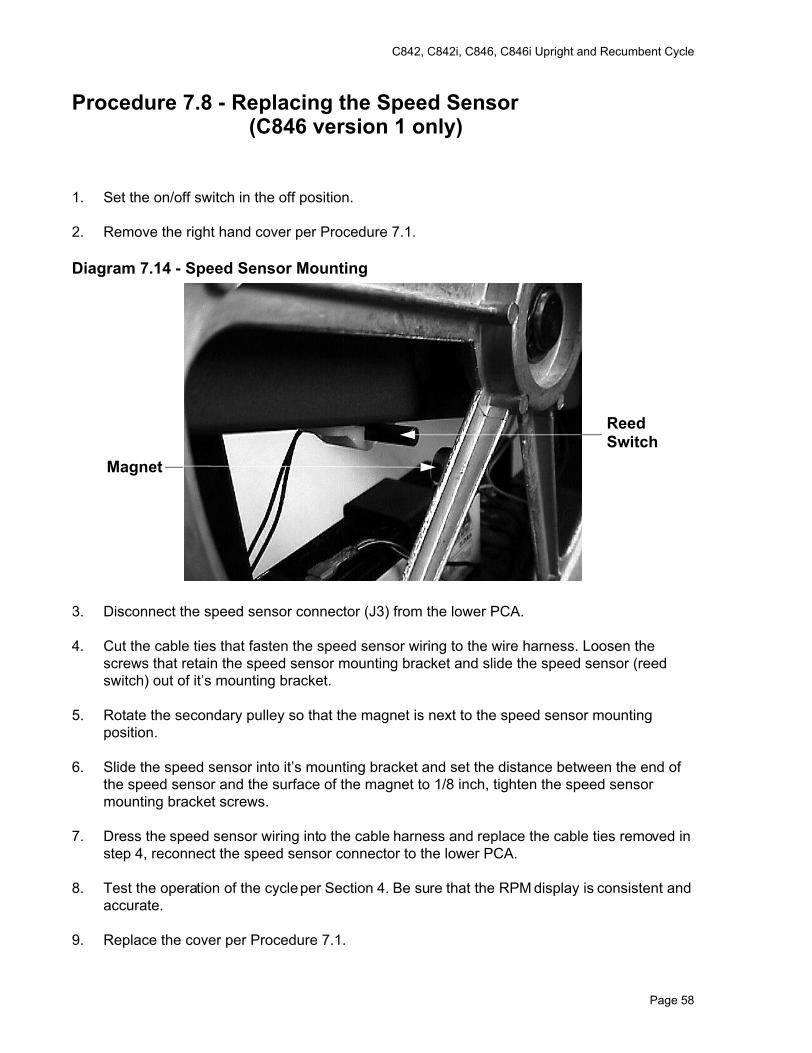
C842, C842i, C846, C846i Upright and Recumbent Cycle
Procedure 7.8 - Replacing the Speed Sensor (C846 version 1 only)
1. Set the on/off switch in the off position.
2. Remove the right hand cover per Procedure 7.1.
Diagram 7.14 - Speed Sensor Mounting
3. Disconnect the speed sensor connector (J3) from the lower PCA.
4. Cut the cable ties that fasten the speed sensor wiring to the wire harness. Loosen the screws that retain the speed sensor mounting bracket and slide the speed sensor (reed switch) out of it’s mounting bracket.
5. Rotate the secondary pulley so that the magnet is next to the speed sensor mounting position.
6. Slide the speed sensor into it’s mounting bracket and set the distance between the end of the speed sensor and the surface of the magnet to 1/8 inch, tighten the speed sensor mounting bracket screws.
7. Dress the speed sensor wiring into the cable harness and replace the cable ties removed in step 4, reconnect the speed sensor connector to the lower PCA.
8. Test the operation of the cycle per Section 4. Be sure that the RPM display is consistent and accurate.
9. Replace the cover per Procedure 7.1.
ReedSwitch
Magnet
Page 58
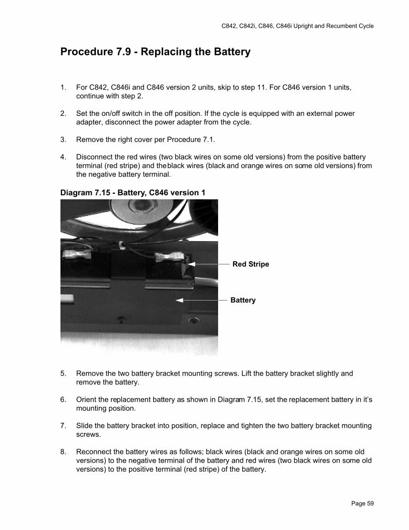
C842, C842i, C846, C846i Upright and Recumbent Cycle
Procedure 7.9 - Replacing the Battery
1. For C842, C846i and C846 version 2 units, skip to step 11. For C846 version 1 units, continue with step 2.
2. Set the on/off switch in the off position. If the cycle is equipped with an external power adapter, disconnect the power adapter from the cycle.
3. Remove the right cover per Procedure 7.1.
4. Disconnect the red wires (two black wires on some old versions) from the positive battery terminal (red stripe) and the black wires (black and orange wires on some old versions) from the negative battery terminal.
Diagram 7.15 - Battery, C846 version 1
5. Remove the two battery bracket mounting screws. Lift the battery bracket slightly and remove the battery.
6. Orient the replacement battery as shown in Diagram 7.15, set the replacement battery in it’s mounting position.
7. Slide the battery bracket into position, replace and tighten the two battery bracket mounting screws.
8. Reconnect the battery wires as follows; black wires (black and orange wires on some old versions) to the negative terminal of the battery and red wires (two black wires on some old versions) to the positive terminal (red stripe) of the battery.
Battery
Red Stripe
Page 59
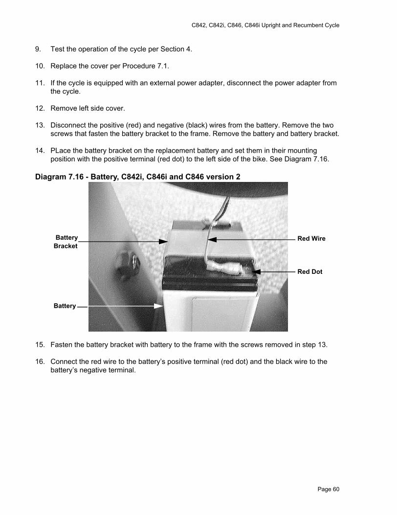
C842, C842i, C846, C846i Upright and Recumbent Cycle
9. Test the operation of the cycle per Section 4.
10. Replace the cover per Procedure 7.1.
11. If the cycle is equipped with an external power adapter, disconnect the power adapter from the cycle.
12. Remove left side cover.
13. Disconnect the positive (red) and negative (black) wires from the battery. Remove the two screws that fasten the battery bracket to the frame. Remove the battery and battery bracket.
14. PLace the battery bracket on the replacement battery and set them in their mounting position with the positive terminal (red dot) to the left side of the bike. See Diagram 7.16.
Diagram 7.16 - Battery, C842i, C846i and C846 version 2
15. Fasten the battery bracket with battery to the frame with the screws removed in step 13.
16. Connect the red wire to the battery’s positive terminal (red dot) and the black wire to the battery’s negative terminal.
Red Wire
Red Dot
BatteryBracket
Battery
Page 60
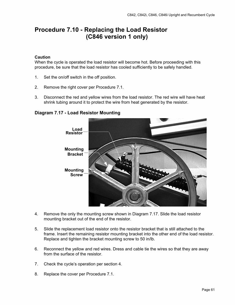
C842, C842i, C846, C846i Upright and Recumbent Cycle
Procedure 7.10 - Replacing the Load Resistor (C846 version 1 only)
Caution When the cycle is operated the load resistor will become hot. Before proceeding with this procedure, be sure that the load resistor has cooled sufficiently to be safely handled.
1. Set the on/off switch in the off position.
2. Remove the right cover per Procedure 7.1.
3. Disconnect the red and yellow wires from the load resistor. The red wire will have heat shrink tubing around it to protect the wire from heat generated by the resistor.
Diagram 7.17 - Load Resistor Mounting
4. Remove the only the mounting screw shown in Diagram 7.17. Slide the load resistor mounting bracket out of the end of the resistor.
5. Slide the replacement load resistor onto the resistor bracket that is still attached to the frame. Insert the remaining resistor mounting bracket into the other end of the load resistor. Replace and tighten the bracket mounting screw to 50 in/lb.
6. Reconnect the yellow and red wires. Dress and cable tie the wires so that they are away from the surface of the resistor.
7. Check the cycle’s operation per section 4.
8. Replace the cover per Procedure 7.1.
LoadResistor
MountingBracket
MountingScrew
Page 61
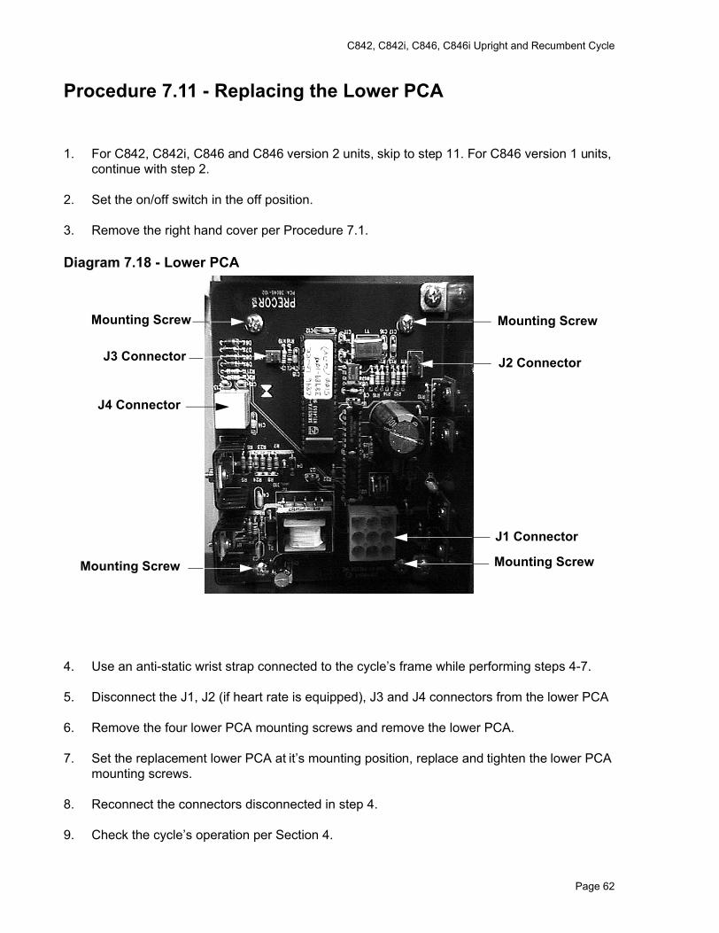
C842, C842i, C846, C846i Upright and Recumbent Cycle
Procedure 7.11 - Replacing the Lower PCA
1. For C842, C842i, C846 and C846 version 2 units, skip to step 11. For C846 version 1 units, continue with step 2.
2. Set the on/off switch in the off position.
3. Remove the right hand cover per Procedure 7.1.
Diagram 7.18 - Lower PCA
4. Use an anti-static wrist strap connected to the cycle’s frame while performing steps 4-7.
5. Disconnect the J1, J2 (if heart rate is equipped), J3 and J4 connectors from the lower PCA
6. Remove the four lower PCA mounting screws and remove the lower PCA.
7. Set the replacement lower PCA at it’s mounting position, replace and tighten the lower PCA mounting screws.
8. Reconnect the connectors disconnected in step 4.
9. Check the cycle’s operation per Section 4.
J1 Connector
J3 Connector
J4 Connector
J2 Connector
Mounting ScrewMounting Screw
Mounting ScrewMounting Screw
Page 62
C842, C842i, C846, C846i Upright and Recumbent Cycle
10. Replace the cover per Procedure 7.1.
11. Disconnect the optional external power adapter, if equipped.
12. Remove the left, right and top covers.
13. Disconnect the red wire from the battery. Disconnect all of the wires from the lower PCA.
14. Remove the four lower PCA mounting screws. Remove the lower PCA.
15. Set the replacement lower PCA at its mounting position, with terminal M1 facing the front of the bike. See Diagram 6.6.
16. Refer to Diagram 6.6 and replace the lower PCA wiring as follows. Connect the wires from the external power jack to connector J4 on the lower PCA. Connect the two red wires from the eddy current magnet to terminals M1 and M2 of the lower PCA (it does not matter which red wire goes on terminal M1 or M2). Connect the red wire from the generator to terminal M3, connect the black wire from the generator to terminal M4 and the white wire from the generator to terminal M5. Connect the interconnect cable to connector J2 on the lower PCA. Connect the black wire from the battery to terminal M7 and the red wire to terminal M6 of the lower PCA.
17. Reconnect the red wire, removed in step 13, to the positive terminal (red dot) of the battery.
18. Reconnect the external power adapter, if equipped.
Page 63
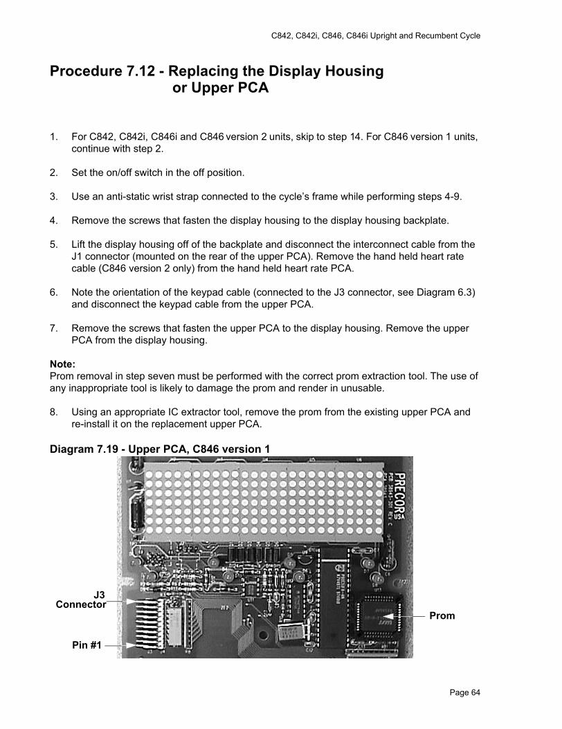
C842, C842i, C846, C846i Upright and Recumbent Cycle
Procedure 7.12 - Replacing the Display Housing or Upper PCA
1. For C842, C842i, C846i and C846 version 2 units, skip to step 14. For C846 version 1 units, continue with step 2.
2. Set the on/off switch in the off position.
3. Use an anti-static wrist strap connected to the cycle’s frame while performing steps 4-9.
4. Remove the screws that fasten the display housing to the display housing backplate.
5. Lift the display housing off of the backplate and disconnect the interconnect cable from the J1 connector (mounted on the rear of the upper PCA). Remove the hand held heart rate cable (C846 version 2 only) from the hand held heart rate PCA.
6. Note the orientation of the keypad cable (connected to the J3 connector, see Diagram 6.3) and disconnect the keypad cable from the upper PCA.
7. Remove the screws that fasten the upper PCA to the display housing. Remove the upper PCA from the display housing.
Note:Prom removal in step seven must be performed with the correct prom extraction tool. The use of any inappropriate tool is likely to damage the prom and render in unusable.
8. Using an appropriate IC extractor tool, remove the prom from the existing upper PCA and re-install it on the replacement upper PCA.
Diagram 7.19 - Upper PCA, C846 version 1
Prom
J3 Connector
Pin #1
Page 64
C842, C842i, C846, C846i Upright and Recumbent Cycle
9. Orient the keypad cable as noted in step 5 and reconnect the keypad cable to the J3 connector.
10. Assemble the replacement or original upper PCA and display housing as required and replace and tighten the upper PCA mounting screws.
11. Reconnect the interconnect cable to the J1 connector.
12. Set the display housing at it’s mounting position on the display backing plate. Replace and tighten display housing mounting screws.
13. Check the cycle’s operation per Section 4.
14. Remove the screws that retain the display, lift the display and disconnect the interconnect cable from the J5 connector and the heart rate cable from the J1 connector (when equipped).
15. Disconnect the keypad cable from the J2 connector.
16. Remove the screws the retain the upper PCA to the display. Remove the upper PCA.
17. Many PCA’s are furnished without software, If your PCA does not have an IC chip installed in the U6 socket, remove the U6 IC chip from the existing PCA (using a IC extractor and anti-static protection) and install it on the replacement PCA.
18. Set the replacement PCA in its mounting position and fasten it with the screws removed in step 16.
19. Connect the keypad cable to the J2 connector.
20. Hold the display near its mounting position and connect the interconnect cable to the J5 connector and the heart rate cable to the J1 connector (when equipped).
21. Set the display in its mounting position and fasten it with the screws removed in step 14.
Page 65
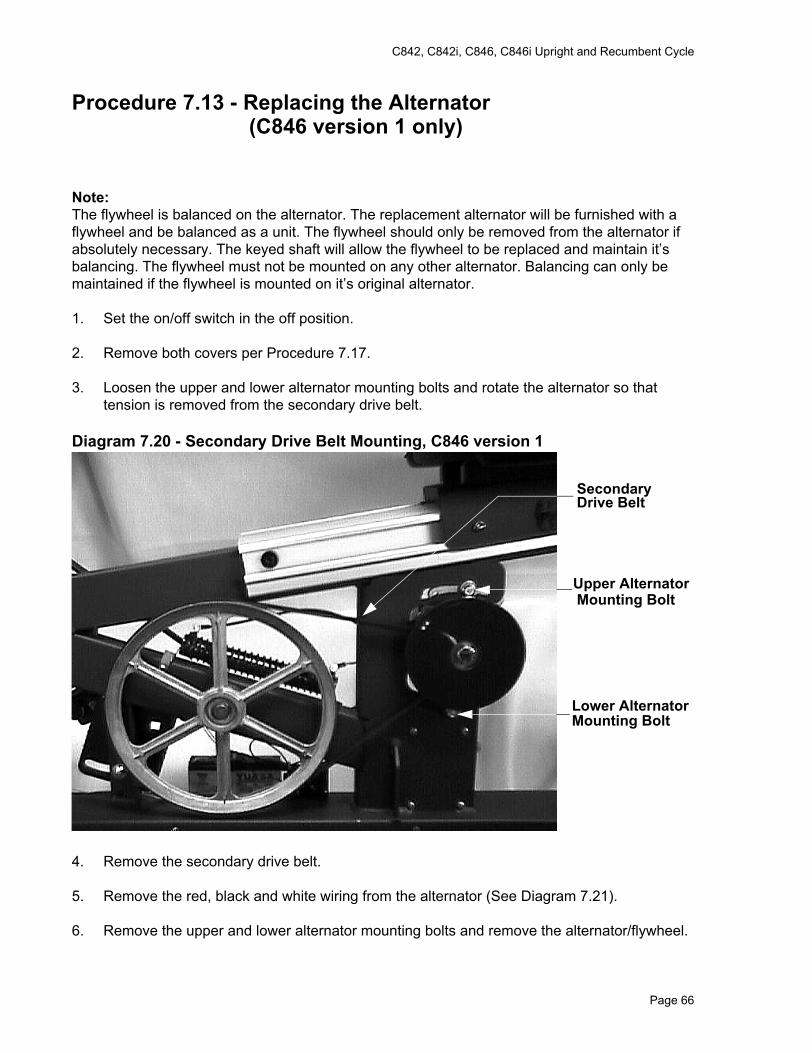
C842, C842i, C846, C846i Upright and Recumbent Cycle
Procedure 7.13 - Replacing the Alternator (C846 version 1 only)
Note:The flywheel is balanced on the alternator. The replacement alternator will be furnished with a flywheel and be balanced as a unit. The flywheel should only be removed from the alternator if absolutely necessary. The keyed shaft will allow the flywheel to be replaced and maintain it’s balancing. The flywheel must not be mounted on any other alternator. Balancing can only be maintained if the flywheel is mounted on it’s original alternator.
1. Set the on/off switch in the off position.
2. Remove both covers per Procedure 7.17.
3. Loosen the upper and lower alternator mounting bolts and rotate the alternator so that tension is removed from the secondary drive belt.
Diagram 7.20 - Secondary Drive Belt Mounting, C846 version 1
4. Remove the secondary drive belt.
5. Remove the red, black and white wiring from the alternator (See Diagram 7.21).
6. Remove the upper and lower alternator mounting bolts and remove the alternator/flywheel.
SecondaryDrive Belt
Upper AlternatorMounting Bolt
Lower AlternatorMounting Bolt
Page 66
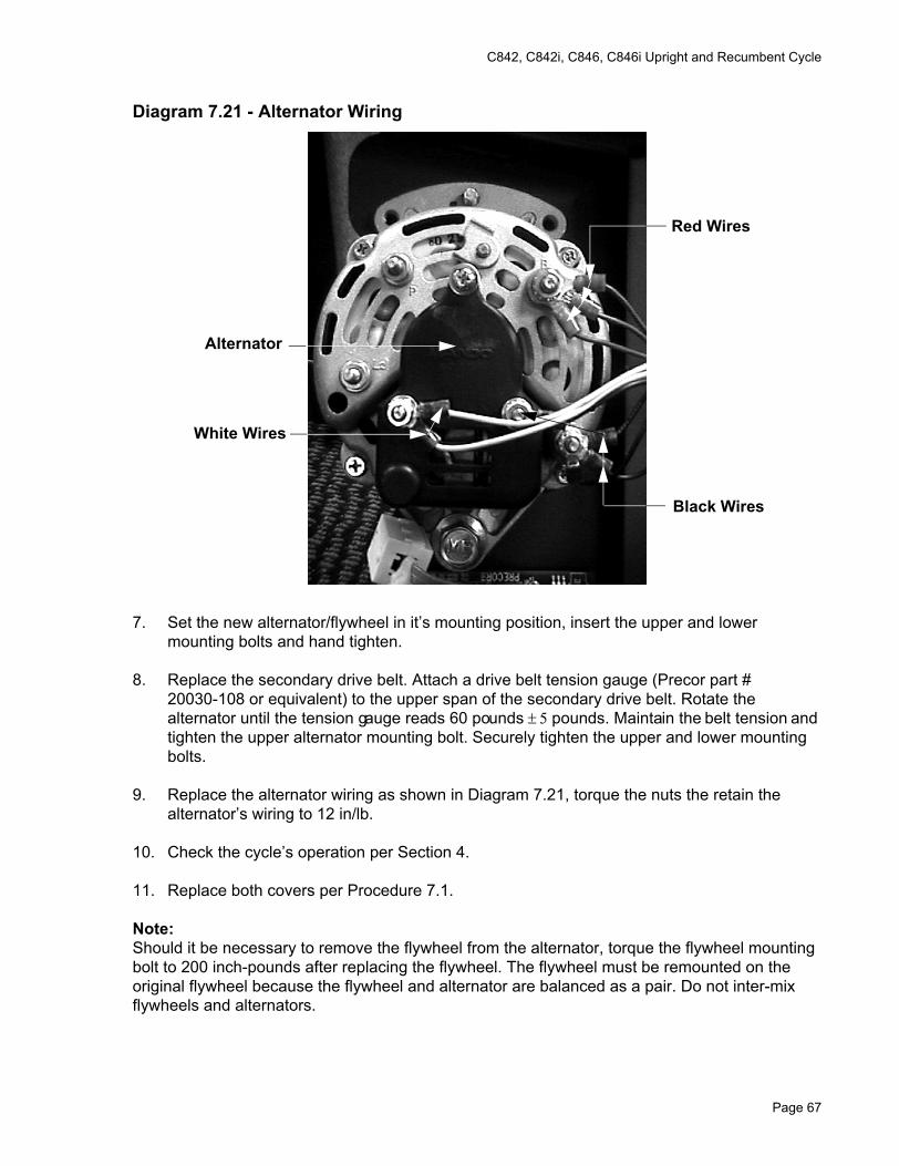
C842, C842i, C846, C846i Upright and Recumbent Cycle
Diagram 7.21 - Alternator Wiring
7. Set the new alternator/flywheel in it’s mounting position, insert the upper and lower mounting bolts and hand tighten.
8. Replace the secondary drive belt. Attach a drive belt tension gauge (Precor part # 20030-108 or equivalent) to the upper span of the secondary drive belt. Rotate the alternator until the tension gauge reads 60 pounds ± 5 pounds. Maintain the belt tension and tighten the upper alternator mounting bolt. Securely tighten the upper and lower mounting bolts.
9. Replace the alternator wiring as shown in Diagram 7.21, torque the nuts the retain the alternator’s wiring to 12 in/lb.
10. Check the cycle’s operation per Section 4.
11. Replace both covers per Procedure 7.1.
Note:Should it be necessary to remove the flywheel from the alternator, torque the flywheel mounting bolt to 200 inch-pounds after replacing the flywheel. The flywheel must be remounted on the original flywheel because the flywheel and alternator are balanced as a pair. Do not inter-mix flywheels and alternators.
Red Wires
Black Wires
White Wires
Alternator
Page 67
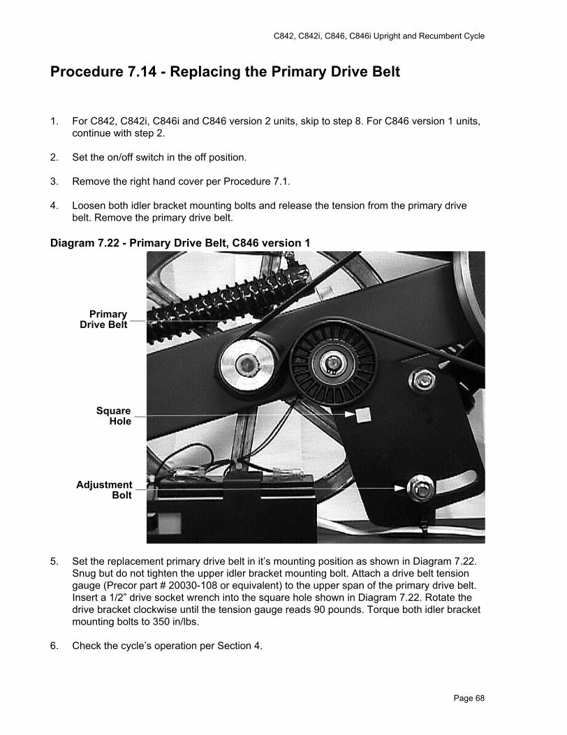
C842, C842i, C846, C846i Upright and Recumbent Cycle
Procedure 7.14 - Replacing the Primary Drive Belt
1. For C842, C842i, C846i and C846 version 2 units, skip to step 8. For C846 version 1 units, continue with step 2.
2. Set the on/off switch in the off position.
3. Remove the right hand cover per Procedure 7.1.
4. Loosen both idler bracket mounting bolts and release the tension from the primary drive belt. Remove the primary drive belt.
Diagram 7.22 - Primary Drive Belt, C846 version 1
5. Set the replacement primary drive belt in it’s mounting position as shown in Diagram 7.22. Snug but do not tighten the upper idler bracket mounting bolt. Attach a drive belt tension gauge (Precor part # 20030-108 or equivalent) to the upper span of the primary drive belt. Insert a 1/2” drive socket wrench into the square hole shown in Diagram 7.22. Rotate the drive bracket clockwise until the tension gauge reads 90 pounds. Torque both idler bracket mounting bolts to 350 in/lbs.
6. Check the cycle’s operation per Section 4.
PrimaryDrive Belt
SquareHole
AdjustmentBolt
Page 68
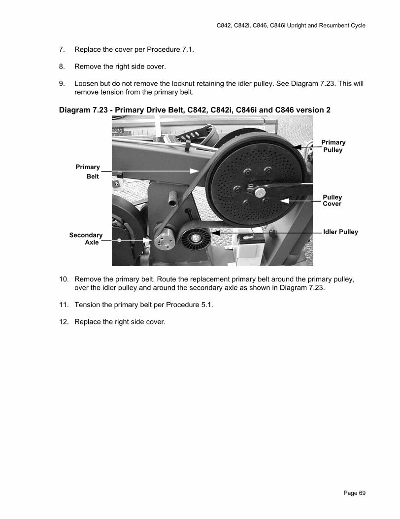
C842, C842i, C846, C846i Upright and Recumbent Cycle
7. Replace the cover per Procedure 7.1.
8. Remove the right side cover.
9. Loosen but do not remove the locknut retaining the idler pulley. See Diagram 7.23. This will remove tension from the primary belt.
Diagram 7.23 - Primary Drive Belt, C842, C842i, C846i and C846 version 2
10. Remove the primary belt. Route the replacement primary belt around the primary pulley, over the idler pulley and around the secondary axle as shown in Diagram 7.23.
11. Tension the primary belt per Procedure 5.1.
12. Replace the right side cover.
PrimaryPulley
Idler Pulley
PrimaryBelt
SecondaryAxle
CoverPulley
Page 69

C842, C842i, C846, C846i Upright and Recumbent Cycle
Procedure 7.15 - Replacing the Secondary Drive Belt
1. For C842, C842i, C846i and C846 version 2 units, skip to step 11. For C846 version 1 units, continue with step 2.
2. Set the on/off switch in the off position.
3. Remove the left hand cover per Procedure 7.1.
4. Loosen the upper and lower alternator mounting bolts and rotate the alternator so that tens
5. rotate the secondary pulley and guide the secondary drive belt off of the secondary pulley.
Diagram 7.24 - Secondary Drive Belt Mounting, C846 version 1
6. Remove the secondary drive belt.
7. Set the replacement secondary drive around the alternator pulley and the upper half of the secondary pulley. Slowly rotate the secondary pulley and guide the secondary drive belt onto the secondary pulley.
8. Re-tension the secondary drive belt per Procedure 5.2.
9. Check the cycle’s operation per Section 4.
SecondaryDrive Belt
Upper AlternatorMounting Bolt
Lower AlternatorMounting Bolt
Page 70
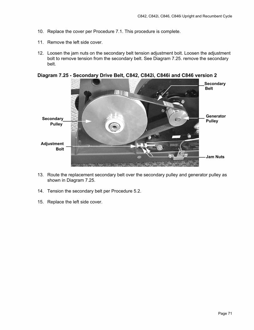
C842, C842i, C846, C846i Upright and Recumbent Cycle
10. Replace the cover per Procedure 7.1. This procedure is complete.
11. Remove the left side cover.
12. Loosen the jam nuts on the secondary belt tension adjustment bolt. Loosen the adjustment bolt to remove tension from the secondary belt. See Diagram 7.25. remove the secondary belt.
Diagram 7.25 - Secondary Drive Belt, C842, C842i, C846i and C846 version 2
13. Route the replacement secondary belt over the secondary pulley and generator pulley as shown in Diagram 7.25.
14. Tension the secondary belt per Procedure 5.2.
15. Replace the left side cover.
SecondaryBelt
GeneratorPulley
Jam Nuts
SecondaryPulley
AdjustmentBolt
Page 71
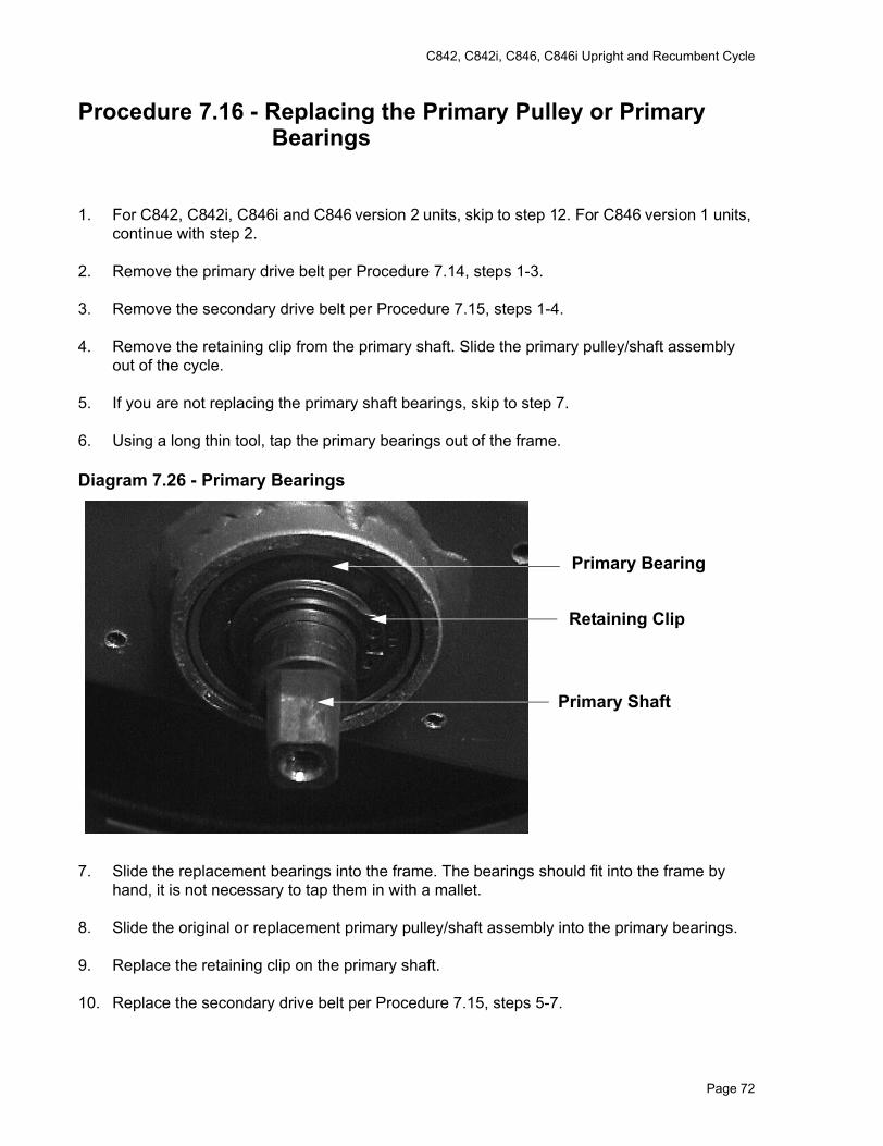
C842, C842i, C846, C846i Upright and Recumbent Cycle
Procedure 7.16 - Replacing the Primary Pulley or Primary Bearings
1. For C842, C842i, C846i and C846 version 2 units, skip to step 12. For C846 version 1 units, continue with step 2.
2. Remove the primary drive belt per Procedure 7.14, steps 1-3.
3. Remove the secondary drive belt per Procedure 7.15, steps 1-4.
4. Remove the retaining clip from the primary shaft. Slide the primary pulley/shaft assembly out of the cycle.
5. If you are not replacing the primary shaft bearings, skip to step 7.
6. Using a long thin tool, tap the primary bearings out of the frame.
Diagram 7.26 - Primary Bearings
7. Slide the replacement bearings into the frame. The bearings should fit into the frame by hand, it is not necessary to tap them in with a mallet.
8. Slide the original or replacement primary pulley/shaft assembly into the primary bearings.
9. Replace the retaining clip on the primary shaft.
10. Replace the secondary drive belt per Procedure 7.15, steps 5-7.
Primary Bearing
Retaining Clip
Primary Shaft
Page 72
C842, C842i, C846, C846i Upright and Recumbent Cycle
11. Replace the primary drive belt per procedure 7.14, steps 4-6. This procedure is complete.
12. Remove the left, right and top covers.
13. Remove the left and right crankarms per Procedure 7.2. Slide the left pulley cover off of the primary pulley axle.
14. Remove the five bolts retaining the right pulley cover. See Diagram 7.23. Remove the right pulley cover.
15. Loosen the idler pulley locknut and release tension from the primary belt.
16. There are two small screws retaining the left and right hand primary pulley bearings in the frame. The screws retaining the left hand bearing are easily visible. The primary pulley has holes in it that will align with and provide access to the right hand bearing retaining screws. Remove all four bearing retaining screws.
17. Remove the large cease nut from the left side of primary pulley shaft. Slide the primary pulley out of the frame. The left hand bearing is in the frame bearing pocket, the right side bearing is part of the primary pulley assembly.
18. If the bearings are being replaced, slide the left hand bearing out of the frame pulley pocket. Slide the replacement bearing into the left hand frame pocket and fasten it with two of the bearing retaining screws removed in step 16.
19. Slide the replace primary pulley assembly into place in the frame. Align the holes in the primary pulley with the bearing retaining holes. Fasten the right hand bearing with the remaining two screws removed in step 16.
20. Thread the large cease nut, removed in step 17 onto the primary pulley shaft and tighten. Do not over tighten the cease nut, the primary pulley must turn freely without any wobble or lateral movement.
21. Set the left hand pulley cover in its mounting position and retain it with screws removed in step 14. Torque the screws to 50 inch pounds. Slide the left pulley cover onto the primary shaft.
22. Replace both crankarms per Procedure 7.2.
23. Tension the primary belt per Procedure 5.1.
24. Replace the left, right and top covers.
Page 73
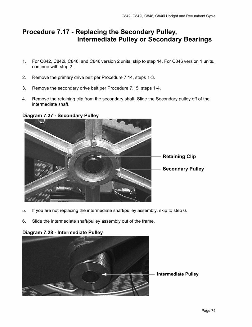
C842, C842i, C846, C846i Upright and Recumbent Cycle
Procedure 7.17 - Replacing the Secondary Pulley, Intermediate Pulley or Secondary Bearings
1. For C842, C842i, C846i and C846 version 2 units, skip to step 14. For C846 version 1 units, continue with step 2.
2. Remove the primary drive belt per Procedure 7.14, steps 1-3.
3. Remove the secondary drive belt per Procedure 7.15, steps 1-4.
4. Remove the retaining clip from the secondary shaft. Slide the Secondary pulley off of the intermediate shaft.
Diagram 7.27 - Secondary Pulley
5. If you are not replacing the intermediate shaft/pulley assembly, skip to step 6.
6. Slide the intermediate shaft/pulley assembly out of the frame.
Diagram 7.28 - Intermediate Pulley
Retaining Clip
Secondary Pulley
Intermediate Pulley
Page 74
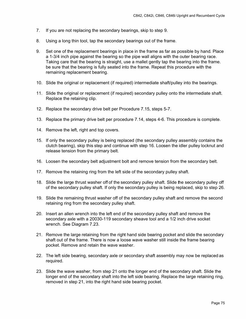
C842, C842i, C846, C846i Upright and Recumbent Cycle
7. If you are not replacing the secondary bearings, skip to step 9.
8. Using a long thin tool, tap the secondary bearings out of the frame.
9. Set one of the replacement bearings in place in the frame as far as possible by hand. Place a 1-3/4 inch pipe against the bearing so the pipe wall aligns with the outer bearing race. Taking care that the bearing is straight, use a mallet gently tap the bearing into the frame. be sure that the bearing is fully seated into the frame. Repeat this procedure with the remaining replacement bearing.
10. Slide the original or replacement (if required) intermediate shaft/pulley into the bearings.
11. Slide the original or replacement (if required) secondary pulley onto the intermediate shaft. Replace the retaining clip.
12. Replace the secondary drive belt per Procedure 7.15, steps 5-7.
13. Replace the primary drive belt per procedure 7.14, steps 4-6. This procedure is complete.
14. Remove the left, right and top covers.
15. If only the secondary pulley is being replaced (the secondary pulley assembly contains the clutch bearing), skip this step and continue with step 16. Loosen the idler pulley locknut and release tension from the primary belt.
16. Loosen the secondary belt adjustment bolt and remove tension from the secondary belt.
17. Remove the retaining ring from the left side of the secondary pulley shaft.
18. Slide the large thrust washer off of the secondary pulley shaft. Slide the secondary pulley off of the secondary pulley shaft. If only the secondary pulley is being replaced, skip to step 26.
19. Slide the remaining thrust washer off of the secondary pulley shaft and remove the second retaining ring from the secondary pulley shaft.
20. Insert an allen wrench into the left end of the secondary pulley shaft and remove the secondary axle with a 20030-119 secondary sheave tool and a 1/2 inch drive socket wrench. See Diagram 7.23.
21. Remove the large retaining from the right hand side bearing pocket and slide the secondary shaft out of the frame. There is now a loose wave washer still inside the frame bearing pocket. Remove and retain the wave washer.
22. The left side bearing, secondary axle or secondary shaft assembly may now be replaced as required.
23. Slide the wave washer, from step 21 onto the longer end of the secondary shaft. Slide the longer end of the secondary shaft into the left side bearing. Replace the large retaining ring, removed in step 21, into the right hand side bearing pocket.
Page 75
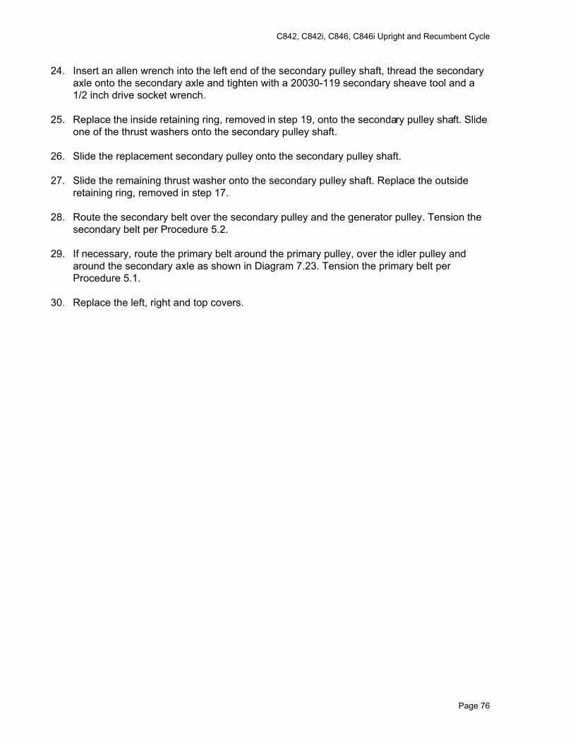
C842, C842i, C846, C846i Upright and Recumbent Cycle
24. Insert an allen wrench into the left end of the secondary pulley shaft, thread the secondary axle onto the secondary axle and tighten with a 20030-119 secondary sheave tool and a 1/2 inch drive socket wrench.
25. Replace the inside retaining ring, removed in step 19, onto the secondary pulley shaft. Slide one of the thrust washers onto the secondary pulley shaft.
26. Slide the replacement secondary pulley onto the secondary pulley shaft.
27. Slide the remaining thrust washer onto the secondary pulley shaft. Replace the outside retaining ring, removed in step 17.
28. Route the secondary belt over the secondary pulley and the generator pulley. Tension the secondary belt per Procedure 5.2.
29. If necessary, route the primary belt around the primary pulley, over the idler pulley and around the secondary axle as shown in Diagram 7.23. Tension the primary belt per Procedure 5.1.
30. Replace the left, right and top covers.
Page 76
C842, C842i, C846, C846i Upright and Recumbent Cycle
Procedure 7.18 - Replacing the Idler Pulley
1. For C842, C842i, C846i and C846 version 2 units, skip to step 8. For C846 version 1 units, continue with step 2.
2. Remove the primary drive belt per Procedure 7.14, steps 1-3.
3. Remove the retaining clip from the idler pulley
Diagram 7.29 - Idler Pulley, C846 version 1
4. Slide the idler pulley off of the idler pulley shaft.
5. Slide the replacement idler pulley onto the idler pulley shaft.
6. Replace the retaining clip.
7. Replace the primary drive belt per procedure 7.14, steps 4-6. This procedure is complete.
8. Remove the right hand cover.
9. Loosen the idler pulley locknut to remove tension from the primary belt. Then remove the idler pulley locknut. Remove the idler pulley from its mounting bolt.
10. Slide the replacement idler pulley onto its mounting bolt and hand start the idler pulley locknut.
11. Tension the primary belt per Procedure 5.1.
12. Replace the right hand cover.
Retaining Clip
Idler Pulley
Page 77
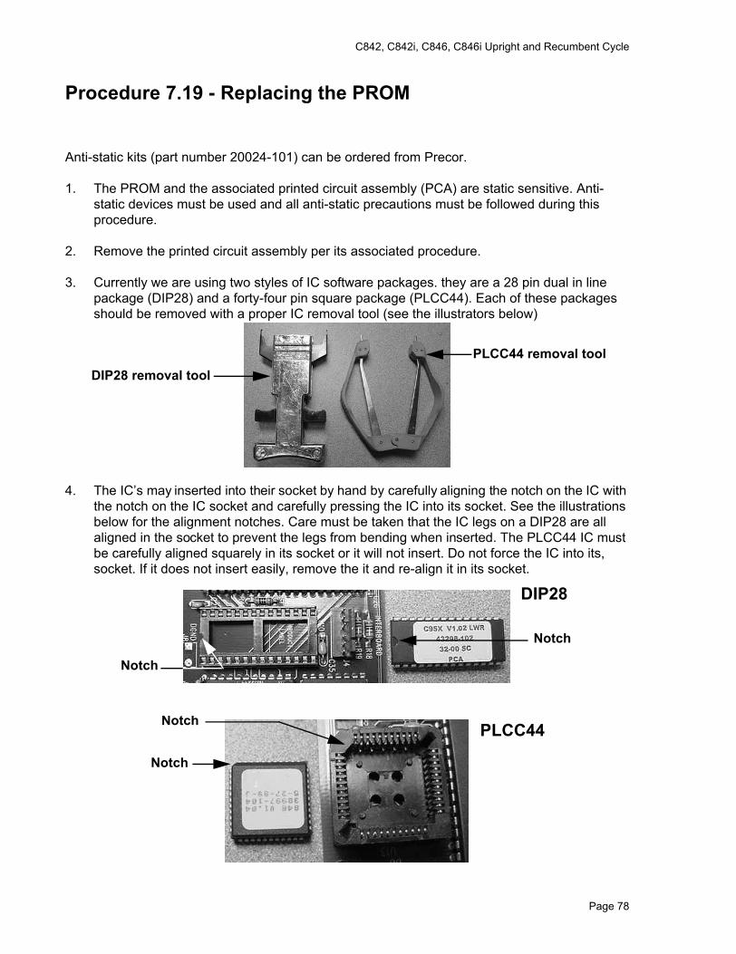
C842, C842i, C846, C846i Upright and Recumbent Cycle
Procedure 7.19 - Replacing the PROM
Anti-static kits (part number 20024-101) can be ordered from Precor.
1. The PROM and the associated printed circuit assembly (PCA) are static sensitive. Anti-static devices must be used and all anti-static precautions must be followed during this procedure.
2. Remove the printed circuit assembly per its associated procedure.
3. Currently we are using two styles of IC software packages. they are a 28 pin dual in line package (DIP28) and a forty-four pin square package (PLCC44). Each of these packages should be removed with a proper IC removal tool (see the illustrators below)
4. The IC’s may inserted into their socket by hand by carefully aligning the notch on the IC with the notch on the IC socket and carefully pressing the IC into its socket. See the illustrations below for the alignment notches. Care must be taken that the IC legs on a DIP28 are all aligned in the socket to prevent the legs from bending when inserted. The PLCC44 IC must be carefully aligned squarely in its socket or it will not insert. Do not force the IC into its, socket. If it does not insert easily, remove the it and re-align it in its socket.
DIP28 removal toolPLCC44 removal tool
Notch
Notch
DIP28
Notch
Notch PLCC44
Page 78
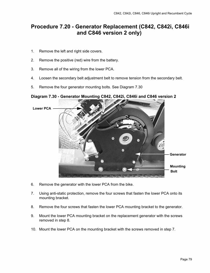
C842, C842i, C846, C846i Upright and Recumbent Cycle
Procedure 7.20 - Generator Replacement (C842, C842i, C846i and C846 version 2 only)
1. Remove the left and right side covers.
2. Remove the positive (red) wire from the battery.
3. Remove all of the wiring from the lower PCA.
4. Loosen the secondary belt adjustment belt to remove tension from the secondary belt.
5. Remove the four generator mounting bolts. See Diagram 7.30
Diagram 7.30 - Generator Mounting C842, C842i, C846i and C846 version 2
6. Remove the generator with the lower PCA from the bike.
7. Using anti-static protection, remove the four screws that fasten the lower PCA onto its mounting bracket.
8. Remove the four screws that fasten the lower PCA mounting bracket to the generator.
9. Mount the lower PCA mounting bracket on the replacement generator with the screws removed in step 8.
10. Mount the lower PCA on the mounting bracket with the screws removed in step 7.
Generator
MountingBolt
Lower PCA
Page 79
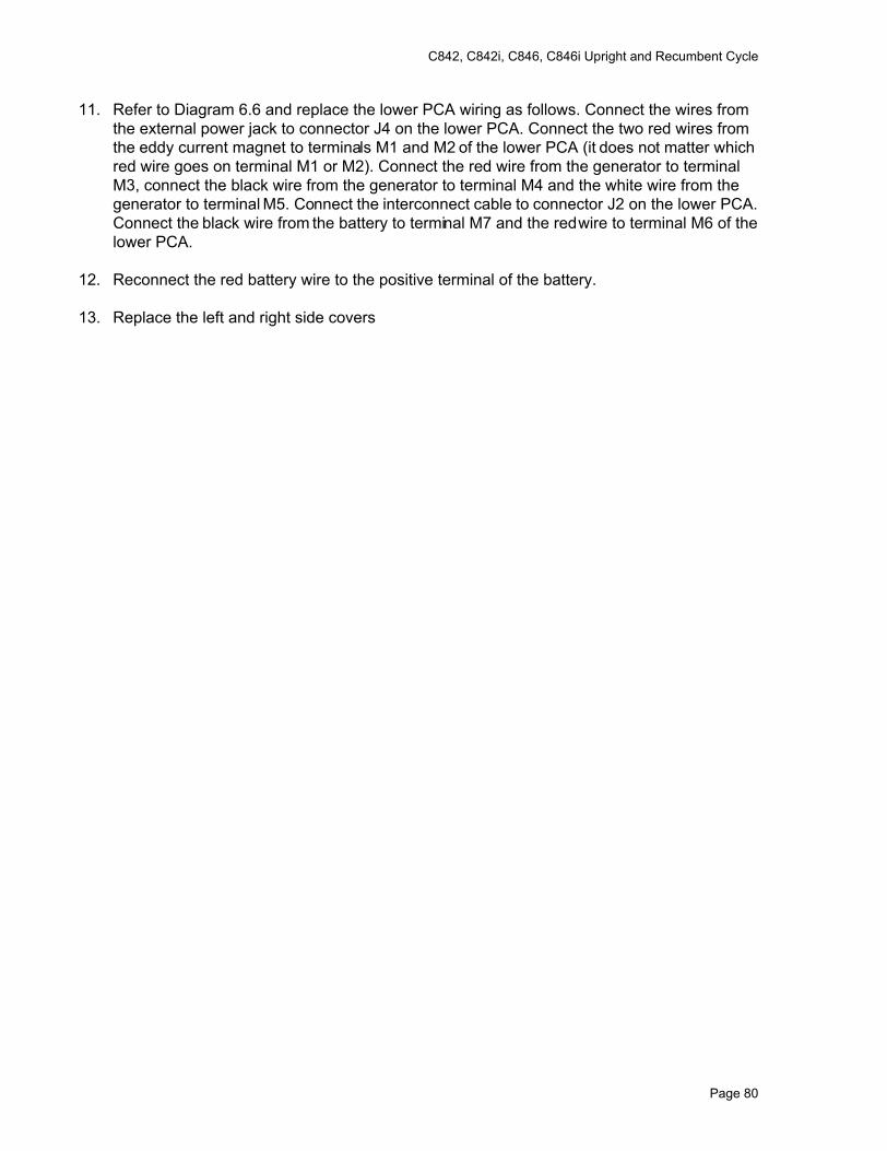
C842, C842i, C846, C846i Upright and Recumbent Cycle
11. Refer to Diagram 6.6 and replace the lower PCA wiring as follows. Connect the wires from the external power jack to connector J4 on the lower PCA. Connect the two red wires from the eddy current magnet to terminals M1 and M2 of the lower PCA (it does not matter which red wire goes on terminal M1 or M2). Connect the red wire from the generator to terminal M3, connect the black wire from the generator to terminal M4 and the white wire from the generator to terminal M5. Connect the interconnect cable to connector J2 on the lower PCA. Connect the black wire from the battery to terminal M7 and the red wire to terminal M6 of the lower PCA.
12. Reconnect the red battery wire to the positive terminal of the battery.
13. Replace the left and right side covers
Page 80
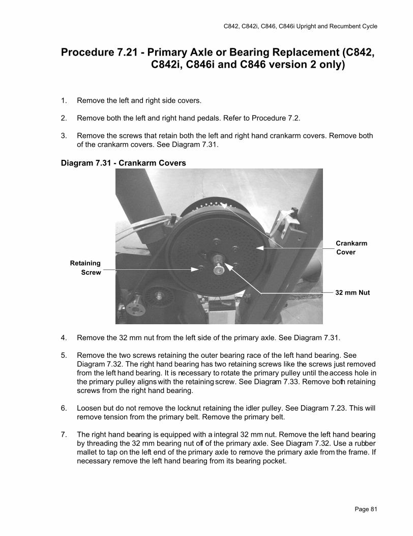
C842, C842i, C846, C846i Upright and Recumbent Cycle
Procedure 7.21 - Primary Axle or Bearing Replacement (C842, C842i, C846i and C846 version 2 only)
1. Remove the left and right side covers.
2. Remove both the left and right hand pedals. Refer to Procedure 7.2.
3. Remove the screws that retain both the left and right hand crankarm covers. Remove both of the crankarm covers. See Diagram 7.31.
Diagram 7.31 - Crankarm Covers
4. Remove the 32 mm nut from the left side of the primary axle. See Diagram 7.31.
5. Remove the two screws retaining the outer bearing race of the left hand bearing. See Diagram 7.32. The right hand bearing has two retaining screws like the screws just removed from the left hand bearing. It is necessary to rotate the primary pulley until the access hole in the primary pulley aligns with the retaining screw. See Diagram 7.33. Remove both retaining screws from the right hand bearing.
6. Loosen but do not remove the locknut retaining the idler pulley. See Diagram 7.23. This will remove tension from the primary belt. Remove the primary belt.
7. The right hand bearing is equipped with a integral 32 mm nut. Remove the left hand bearing by threading the 32 mm bearing nut off of the primary axle. See Diagram 7.32. Use a rubber mallet to tap on the left end of the primary axle to remove the primary axle from the frame. If necessary remove the left hand bearing from its bearing pocket.
CrankarmCover
RetainingScrew
32 mm Nut
Page 81
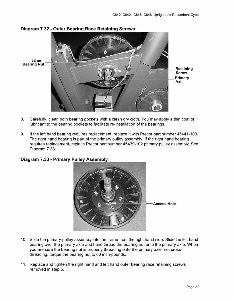
C842, C842i, C846, C846i Upright and Recumbent Cycle
Diagram 7.32 - Outer Bearing Race Retaining Screws
8. Carefully, clean both bearing pockets with a clean dry cloth. You may apply a thin coat of lubricant to the bearing pockets to facilitate re-installation of the bearings.
9. If the left hand bearing requires replacement, replace it with Precor part number 45441-103. The right hand bearing is part of the primary pulley assembly. If the right hand bearing requires replacement, replace Precor part number 45439-102 primary pulley assembly. See Diagram 7.33.
Diagram 7.33 - Primary Pulley Assembly
10. Slide the primary pulley assembly into the frame from the right hand side. Slide the left hand bearing over the primary axle and hand thread the bearing nut onto the primary axle. When you are sure the bearing nut is properly threading onto the primary axle, not cross-threading, torque the bearing nut to 60 inch-pounds.
11. Replace and tighten the right hand and left hand outer bearing race retaining screws removed in step 5.
Retaining Screw
32 mmBearing Nut
PrimaryAxle
Access Hole
Page 82
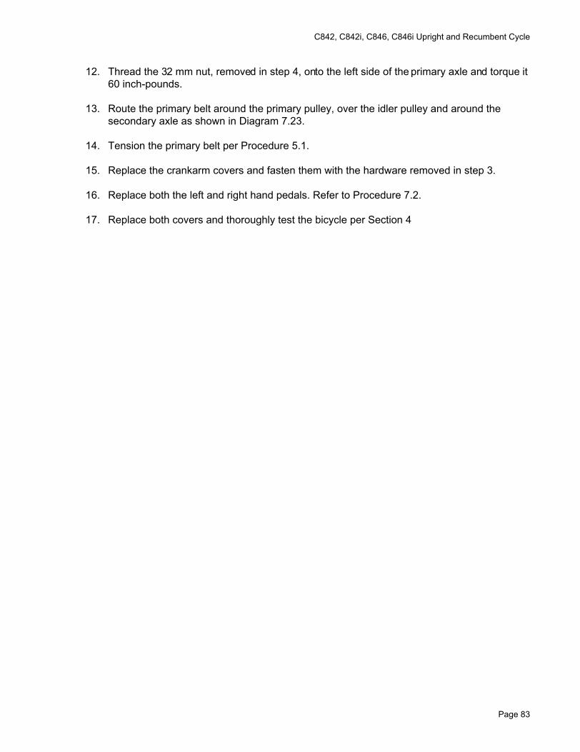
C842, C842i, C846, C846i Upright and Recumbent Cycle
12. Thread the 32 mm nut, removed in step 4, onto the left side of the primary axle and torque it 60 inch-pounds.
13. Route the primary belt around the primary pulley, over the idler pulley and around the secondary axle as shown in Diagram 7.23.
14. Tension the primary belt per Procedure 5.1.
15. Replace the crankarm covers and fasten them with the hardware removed in step 3.
16. Replace both the left and right hand pedals. Refer to Procedure 7.2.
17. Replace both covers and thoroughly test the bicycle per Section 4
Page 83
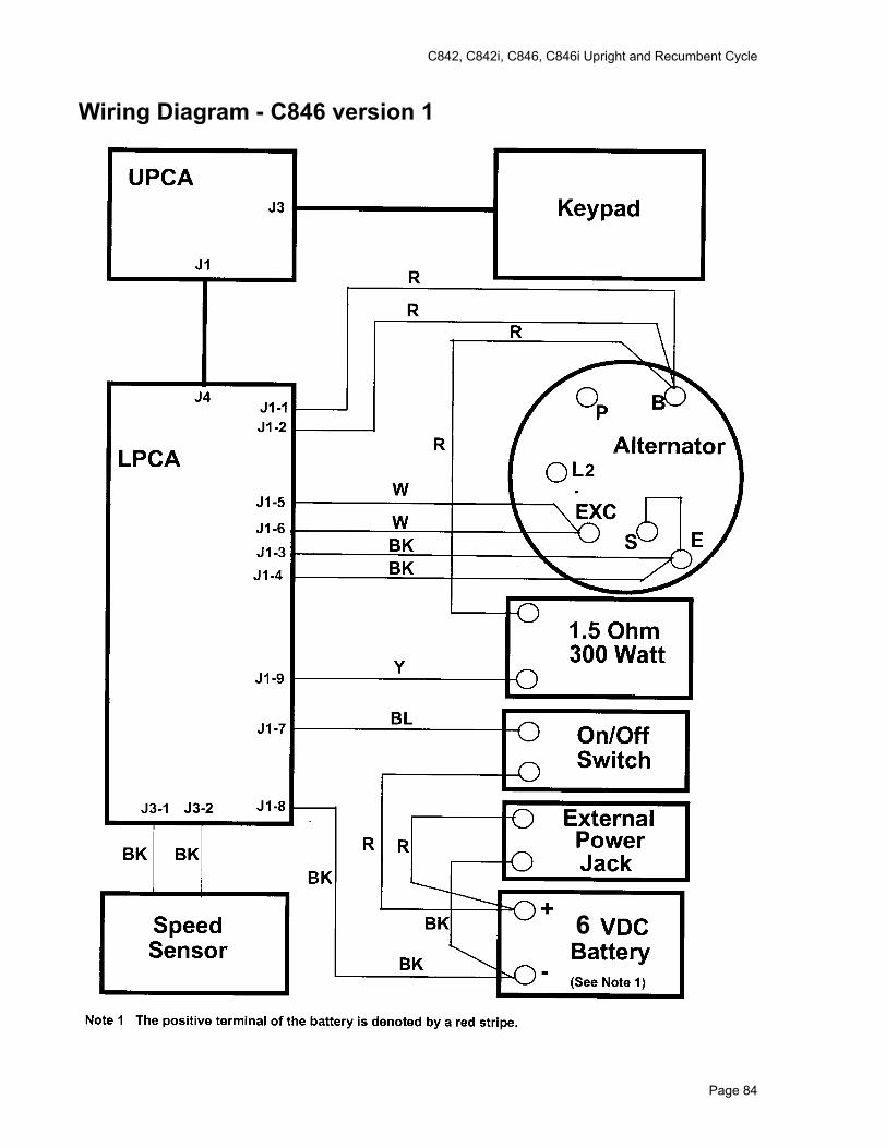
C842, C842i, C846, C846i Upright and Recumbent Cycle
Wiring Diagram - C846 version 1
6
Page 84
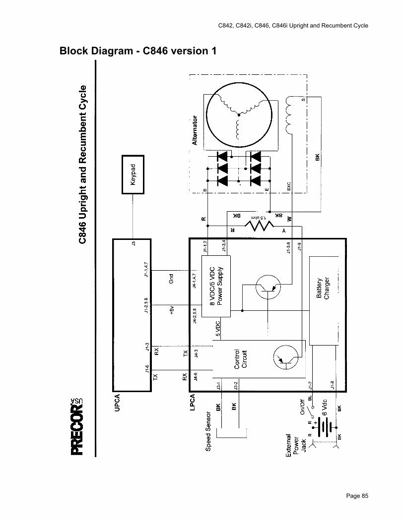
C842, C842i, C846, C846i Upright and Recumbent Cycle
Block Diagram - C846 version 1
Page 85
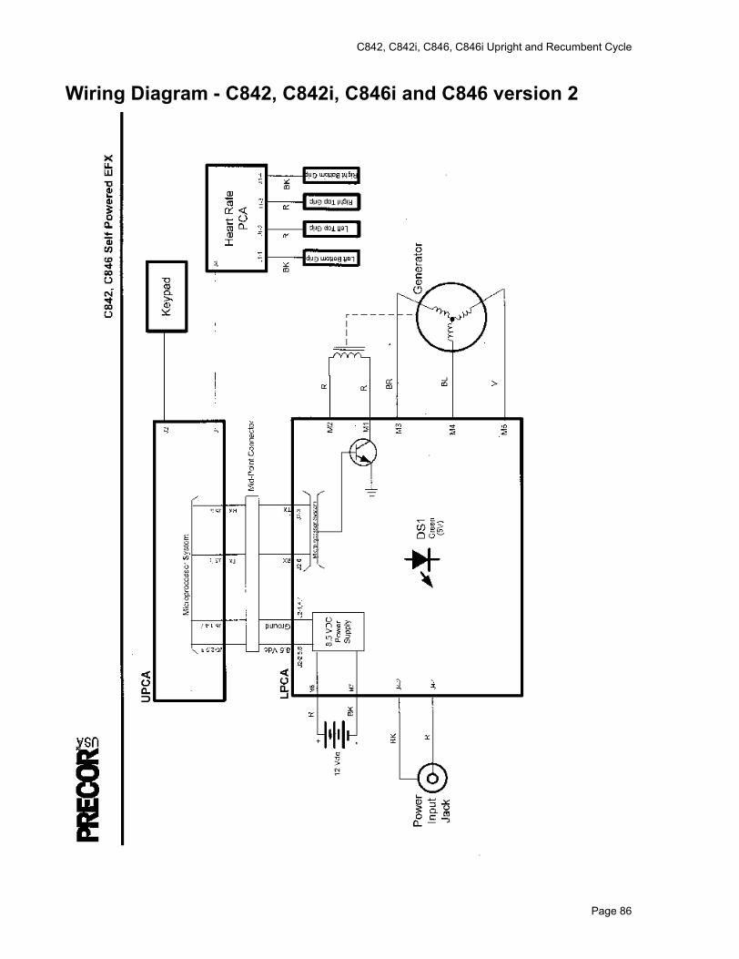
C842, C842i, C846, C846i Upright and Recumbent Cycle
Wiring Diagram - C842, C842i, C846i and C846 version 2
Page 86
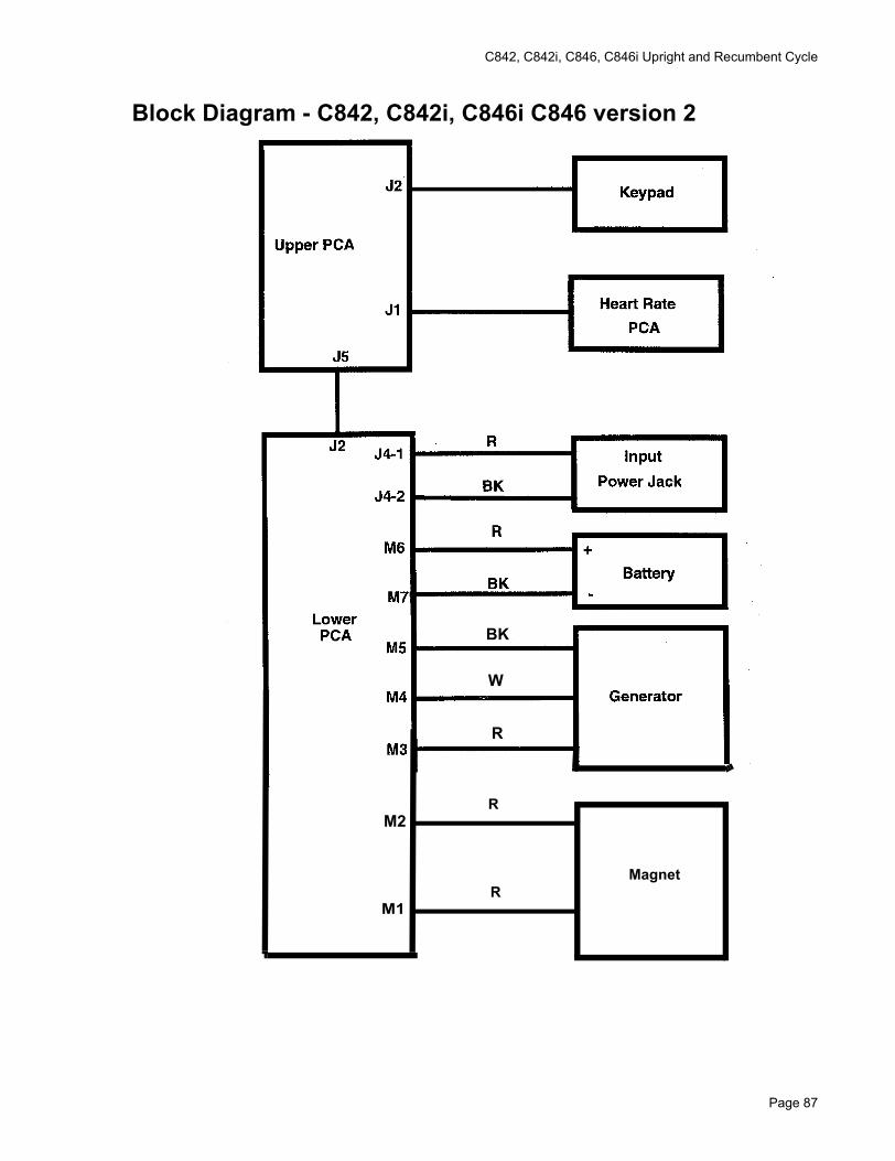
C842, C842i, C846, C846i Upright and Recumbent Cycle
Block Diagram - C842, C842i, C846i C846 version 2
BK
W
R
M2
M1
Magnet
R
R
Page 87