service manual - cab
TRANSCRIPT

Service Manual
1000Applicator

2 2
Family TypeApplicator 1000
Edition: 08/2010 - Part No. 9009031
CopyrightThis documentation as well as translation hereof are property of cab Produkttechnik GmbH & Co. KG. The replication, conversion, duplication or divulgement of the whole manual or parts of it for other intentions than its original intended purpose demand the previous written authorization by cab.
EditorRegarding questions or comments please contact cab Produkttechnik GmbH & Co. KG.
TopicalityDue to the constant further development of our products discrepancies between documentation and product can occur.Please check www.cab.de for the latest update.
Terms and conditionsDeliveries and performances are effected under the General conditions of sale of cab.
Service Manual for the following products
Germanycab Produkttechnik GmbH & Co KG
Postfach 1904 D-76007 Karlsruhe Wilhelm-Schickard-Str. 14 D-76131 KarlsruheTelefon +49 721 6626-0 Telefax +49 721 6626-249www.cab.de [email protected]
France cab technologies s.a.r.l. F-67350 Niedermodern Téléphone +33 388 722 501
www.cab.de [email protected]
España cab España S.L. E-08304 Montaró (Barcelona) Teléfono +34 937 414 605
www.cab.de [email protected]
USA cab Technology Inc. Tyngsboro MA, 01879 Phone +1 978 649 0293
www.cabtechn.com [email protected]
South Afrika cab Technology (Pty.) Ltd. 2125 Randburg Phone +27 11-886-3580
www.cab.de [email protected]
[email protected] +86 21 6236-3161
2299 11C60
cab (Shanghai) Trading Co.,Ltd
cab Technology Co, Ltd.
Junghe 23552, Taipei, TaiwanPhone +886 2 8227 3966
Asia
Representatives in other countries on request.

2 3Table of Contents
1 Introduction ............................................................................................................................................ 41.1 Instructions ............................................................................................................................................... 41.2 Safety Instructions .................................................................................................................................... 51.3 Environment ............................................................................................................................................. 5
2 Product Description ............................................................................................................................... 62.1 Device Overview ...................................................................................................................................... 62.2 Function ................................................................................................................................................... 8
3 Maintenance / Cleaning ....................................................................................................................... 103.1 Tools ....................................................................................................................................................... 103.2 Cleaning ................................................................................................................................................. 10
4 Replace Assembly Units...................................................................................................................... 114.1 Instructions for sticking Slide Foil onto the Pad .....................................................................................114.2 Change Valves ....................................................................................................................................... 124.3 Change PCB Applicator Control ............................................................................................................. 134.4 Change Controller .................................................................................................................................. 134.5 Change PCB Applicator Interfaces ......................................................................................................... 144.6 Change Cylinder .................................................................................................................................... 144.7 Change Sensors On The Cylinder ......................................................................................................... 15
5 Troubleshooting and Fault Clearance ............................................................................................... 165.1 Check Sensor Labeling Position / Sensor Start Position ....................................................................... 165.2 Status LED ............................................................................................................................................. 165.3 Pressure Measurement .......................................................................................................................... 175.4 Error Indication ....................................................................................................................................... 18
6 Block Diagram ...................................................................................................................................... 20
7 Pneumatic Drawing .............................................................................................................................. 21
8 Index ...................................................................................................................................................... 22

4 4
1.1 InstructionsImportant information and instructions in this documentation are designated as follows:
Danger!Draws your attention to an exceptionally grave, impending danger to your health or life.
!Warning!Indicates a hazardous situation that could lead to injuries or material damage.
!Attention!Draws attention to possible dangers, material damage or loss of quality.
iNotice! Gives you tips. They make a working sequence easier or draw attention to important working processes.
Environment!Gives you tips on protecting the environment.
Handling instruction
Reference to section, position, illustration number or document.
Option (accessories, peripheral equipment, special fittings).
1 Introduction

4 5
1.2 Safety Instructions• Only connect the device to other devices which have a protective low voltage.• Before mounting the delivered components disconnect the printer from the power supply and close the shutoff
valve at the applicator.• The device may only be used in a dry environment, do not expose it to moisture (sprays of water, mists, etc.).
!Warning!In case of working on the applicator disconnect the printer of the power supply and close the pressure air.
!Warning!In operation, moving parts are easily accessible. This applies especially for the zone, where the pad is moved between the starting and the labelling position. During operation do not reach into that zone and keep long hair, loose clothes, and jewelry distant. Before any manipulations in those areas, close the shutoff valve.
!Warning!Don't change the device in a kind which not described in the documentation of the printer and applicator.
1.3 Environment
Obsolete devices contain valuable recyclable materials that should be sent for recycling. Send to suitable collection points, separately from residual waste.
The modular construction of the print module enables it to be easily disassembled into its component parts. Send the parts for recycling.
1 Introduction

6 6
2.1 Device OverviewView A View B
2 Product Description
1 Energy Track 9 Sensor Start Position2 Knurled Screw 10 Set Screw vertical3 Set Screw horizontal 11 Throttle Valve Lift Cylinder (bottom) 4 Connector Compressed Air 12 Pad Retainer5 Shut Down Valve 13 Pad ( customized)6 Cylinder 14 Blow Tube 7 Throttle Valve lift Cylinder (top) 15 Connector Applicator - Printer8 Stopper 16 Labelling Sensor
Fig. 1 Overview
7
6
10
11
12
14
13
1
4
5
23
13
12
11
6
878
14
15
32
9
16

6 72 Product Description
View C
Fig. 2 Overview
17 Valve Block 24 Vacuum Generator18 Valve Cylinder 25 PCB Applicator Control19 Valve Blow Air 26 Controller20 Valve Vacuum / Support Air21 Switch to the valve control by hand22 Switch to the valve control by hand23 Sensor for vacuum on the PCB Applicator
Interfaces
17
18192021
22
24
23
26
25

8 82 Product Description
2.2 Function
2.2.1 Sensors
Sensor Labeling positionThe contact of the pad onto the product or the reaching of the release position is detected by a Hall-sensor. For which purpose the displacement of the adapter bolt in relation to the sensor is used.
Sensor Start PositionThe start position is the upper end position of cylinder and the position of the pad which takeover the label from printer. This position will detected via a Hall-sensor in interaction with a magnet mounted inside cylinder.
Sensor VacuumThe correct transfer of a label will checked by the vacuum sensor. It also check that there is no longer a label on the pad in case the return movement. This sensor is integrated on the PCB applicator interfaces.
Sensor Pressure AirThe pressure sensor controls the pressure air. This sensor is integrated on the PCB applicator interfaces.
2.2.2 Pneumatics
CylinderA cylinder with stroke of 100-400 mm is used for the transport of labels between the dispense edge of the printer and the labelling position. It will controlled by the "cylinder" valve. The speed of movement can be changed by two throttle valves mounted at cylinder.
PadThe label will be transported by a pad. The pad must be appropriate to the size of label. The pad assembly and cylinder are conjoint and it will range by the cylinder.In case of a label transportation it's a vacuum applied on the pad.When the applicator will used in 'blow' mode, the label will be apply by a high pressure.
Vacuum GeneratorThe vacuum at the pad will produced by a vacuum generator. The vacuum generator is controlled by the vacuum valve "Vakuum". It's possible to adjust the low pressure by a throttle valve.
Blow TubeAir is blown from below (supporting air) trough a blow tube onto the label in order to support the transfer of the label from the printer to the pad. It's possible to adjust he direction of the blast. The supporting air is switched on by the supporting air valve "Stützluft"
Pneumatic Maintenance UnitThe pneumatic maintenance unit is offered as an option for the applicator. The important components of the pneumatic maintenance unit are a pressure reducer with manometer, a water separator with micro filter and a main connector for compressed air
Valve BlockThe distribution of the compressed air to the various pneumatic units is made in the valve block.On the valve block is mounted the control valve for vacuum and support air in combination with throttle valves and the control valves for lift cylinder an blow air.

8 9
ValvesFor control and adjust works its possible to start a valve direct by hand via an integrated switch.You can see the valves only with dismounted cover.
Loosen screws (1) and remove cover (2) .Via integrated Keys (3-8) you can switch the pneumatic valves by hand.
Three way valve (9) to control the lift cylinderIs the printer switched on the valve will be electrical controlled and the pad will move to the start position and hold on this place. In case of switching the valve the pad will move to the labelling position. In normal labelling operation the valve switched again after the signal of the labelling sensor.
i Notice! The manually control of the valves is only possible when the printer is switched off.
When switching the valve via the key 3 the pad will moved down to the most bottom position. It doesn't use the stop signal from the labelling sensor.Switch key 4 and the pad will move up.
Double two way valve (10) to control the blow airIn the operation mode "blow" the label will blow on the product trough switch on the blow air on the pad.in the operation modes "stamp" and "roll on" will start the blow air for a short time in the movement back to the start position to clean all holes in the pad.
For all described function the both integrated valves will switched parallel.When switching the valves (blow air) manually by switch 5 and 6 there used only one of the two integrated valves.
Double two way valve (11) to control the vacuum / support airThe both internal valves attend to switch on the vacuum generator , to create a depression on the pad and independent of there to control the support air on the blow tube.switch 7 switched the support air and switch 8 the vacuum.
2 Product Description
3 4 5 6 7 8
Fig. 3 Dismount cover Fig. 4 Pneumatic control valves
1
2
1
9
10
11

10 10
! Attention!Pull tubes (1) at pneumatic connectors only if the releasing ring (2) pressed. (Figure 6 right).
3 Maintenance / Cleaning
3.2 Cleaning
! Attention!Never use solvent and abrasive.
Clean the outside surfaces with multi purpose cleaner.
In regularly function it's possible that accrue dust particles and label splits. Remove that by a soft brush or/and a vacuum cleaner.
Especially at slide foil (1) it's possible that fouling deposit. To receive an ideal takeover and handling of the label it's necessary to clean the surface of slide foil at regular intervals.
3.1 ToolsAll tools you need for repair the applicator
Fig. 6 Pad with slide foil
Tools Size for Assembliescombination wrench 5,5 mm cylinder plunger
9,0 mm throttle valve10,0 mm guide rod14,0 mm L-connector (valve block > pneumatic maintenance unit)20,0 mm lift cylinder
hexagon wrench 2,0 mm valve block, energy track ... 2,5 mm PCB ... 5,0 mm adjustment guiding block
screwdriver for slotted screws 2,5 mm throttle valvescrosstip screwdriver PH0 valves on the valve block
PH2 Sensors on cylinderPC-Extractor changing controller
wrist grounding for works at PCB and controllermanometer to 5 bar pressure measurementsoft brush, cloth, multi purpose cleaner (without solvent))
1
2
Fig. 5 Push (left) and pull (right) of tubes
Table 2 Tools and their purpose
1
1

10 11
Dismount Cover
1. Loosen screws (1).2. Remove cover in direction of arrow.
4 Replace Assembly Units
To divide on the mother plate to arrive it's necessary to dismount the cover. Before the regular work will start it's absolutely necessary to mount the cover again.
!Warning!Attend that the printer power supply is disconnected and the compressed air supply is closed before starts the mounting works.
4.1 Instructions for sticking Slide Foil onto the Pad
1. Dismount the pad unit.2. Make a note of the hole pattern on the slide foil.3. Remove the slide foil completely.4. Clear the surface from remains of glue.5. Remove covering foil from the slide foil. 6. Put the slide foil (1) with its adhesive side onto the pad (2). 7. Press the slide foil firmly on the pad.8. Cut off those parts of the slide foil (1) (along the broken
line) that jut out over the edge of the pad (2). 9. Punch the slide foil on the pad (2) using the punch pin (3)
appropriate to the hole pattern on the wearing slide foil. 10. Punch the hole completely by turning the pin.11. Mount the pad unit.
12
2
3
! Attention!Mount the cover again before you start the normal operation!
Fig. 8 Sticking the slide foil /Punching the holes
1
2
1
Fig. 7 Cover mount and dismount

12 12
4.2 Change Valves
!Warning!Attend that the printer power supply is disconnected and the compressed air supply is closed before starts the mounting works.
4 Replace Assembly Units
Fig. 9 Change valves
1. Remove the cover.2. Loosen screws (5) from bracket (4) and the PCB valve block (1). 3. Remove bracket (4).4. Loosen screws (3) of the to switch valve.5. Change valve (2a,b or c).6. Tighten screws(3) of the changed valve.7. Set on the bracket (4) to the PCB valve block (1) and tighten it with the screws (5).8. Mount the cover again.
2a
3
4
5
1
2b2c

12 13
4.3 Change PCB Applicator Control
! Attention!Protection against electrostatic discharge before work grounding
1. Dismount the cover.2. Pull PCB (2) out from the connector (3) of the interface to
the PCB Applicator Interfaces.3. Pull the PCB (2) in the guiding (1) out of the device.4. Mounting in reverse order.
4 Replace Assembly Units
Fig. 10 Change PCB Applicator Control
4.4 Change Controller
! Attention!Protection against electrostatic discharge before work grounding
! Attention!Remove controller only with a special tool
1. Dismount PCB Applicator Control described like chapter 4.3.
2. Replace controller (1) with PC-Extractor (3) from the socket.
3. Put in Controller (1). Look at the marker! half round marker on Controller half round marker on Socket
4. Mount PCB Applicator Control like chapter 4.3 .
1
2
3
Fig. 11 Change Controller
1
2
3
1

14 14
4.6 Change Cylinder
!Warning!Attend that the printer power supply is disconnected and the compressed air supply is closed before starts the mounting works.
1. Dismount sensor start position (1) with sensor collar and remove all tubes from cylinder (2).
2. Remove throttle valves (3) from cylinder (2).3. Remove lock washer (8) and the two other washer.4. Pull guide down from adapter bolt (6) and take out the
spring (7). 5. Hold the adapter bolt (6) on the hole with a tool and
unscrew the piston (4) with a 5,5 mm wrench from adapter bolt.
6. Loosen nut (5) and take out cylinder (2).7. Put in the new cylinder (2) and attach it with nut (5).8. Tighten the adapter bolt (6) on the piston (4) of the cylinder.9. Attach the spring (7) to the guide and press the guide at
the top. Press the adapter bolt toward the guide.10. Attach the washer and fix it with the lock washer (8). 11. Mount throttle valves (3) .12. Mount again sensor start position (1) and all tubes.
Fig. 13 Change cylinder
4 Replace Assembly Units
Fig. 12 Change PCB Applicator Interfaces
3
2
5
1
6
7
4
8
3
2
14
2
4.5 Change PCB Applicator Interfaces
!Warning!Attend that the printer power supply is disconnected and the compressed air supply is closed before starts the mounting works.
1. Remove cover.2. Detach all tubes from valve block (4).3. Loosen screws (1) and move out valve block (4).4. Remove PCB Applicator Control.5. Loosen screws (2) and remove PCB Applicator Interfaces
(3).6. Mounting of the PCB Applicator Interfaces (3) in reverse
order.

14 15
4.7 Change Sensors On The Cylinder
!Warning!Attend that the printer power supply is disconnected and the compressed air supply is closed before starts the mounting works.
1. Remove cover.2. Remove the connector of the sensor, you would change.
Slot CON 11 (6) Sensor Start Position (2)Slot CON 12 (5) Sensor Labelling Position (1)
3. Dismount sensor:
Sensor Labelling Position (1)
Loosen screws (5) to dismount the energy track on one side only.
Detach the into one another looked divide in T-form (7) from the divide in U-form (8) of the energy track. (Figure 17)
Pull out the dismounted sensor. Replace the sensor. Close the energy track again. Press in the T-form (7)
pieces into the U-form (8) pieces.
Sensor Start Position (2)
Remove the cable clip from the cylinder. Loosen the screw of the sensor an remove the sensor. Change sensor start position (2) .
4. Mounting of new sensors in reverse order.
iNotice! After replacing a sensor it's necessary to adjust the sensor position new. chapter 5.1
4 Replace Assembly Units
Fig. 16 Interfaces sensors
Fig. 17 Open of the energy track - Sensor labelling position
Fig. 14 Sensor labelling position / sensor start position
2
1
7 8
5
6
Fig. 15 Cable run
34
16 16
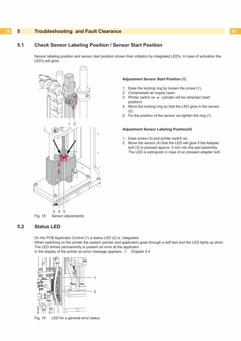
5.1 Check Sensor Labeling Position / Sensor Start Position
Sensor labeling position and sensor start position shown their initiation by integrated LED's. In case of activation the LED's will glow.
Adjustment Sensor Start Position (1)
1. Ease the locking ring by loosen the screw (1).2. Compressed air supply open.3. Printer switch on cylinder will be retracted (start
position)4. Move the locking ring so that the LED glow in the sensor
(2).5. Fix the position of the sensor via tighten the ring (1)
Adjustment Sensor Labeling Position(4)
1. Ease screw (3) and printer switch on.2. Move the sensor (4) that the LED will glow if the Adapter
bolt (3) is pressed approx. 5 mm into the pad assembly. The LED is extinguish in case of an pressed adapter bolt.
5 Troubleshooting and Fault Clearance
Fig. 18 Sensor adjustments
1 2
543
Fig. 19 LED for a general error status
5.2 Status LED
On the PCB Applicator Control (1) a status LED (2) is integrated.When switching on the printer the system (printer and applicator) goes through a self test and the LED lights up short. The LED shines permanently is present an error at the applicator . In the display of the printer an error message appears. Chapter 5.4
1
2

16 17
Reading points (RP) of pressure values.
RP 1 : Support air (reference value 2 to 2,5 bar)1. Remove cover. 1. Consecutively connect the manometer on RP 1.
- Tube (5) from valve block to blow tube connector. - L-Fitting (6) on the blow tube.
2. Activate the valve manually to measure the pressure.3. As and when required adjust it on support air throttle valve
(1).4. Mount cover again.
RP 2 : Vacuum (reference value -0,3 to -0,6 bar) 1. Remove cover.1. Close suction plate hermetic.2. Attach manometer between measurement points RP 4.
- T-Fitting (3) on the vacuum generator - Tube (4) from vacuum generator to the pad
3. Open the air supply and activate the valve manually to measure the pressure.
4. As and when required adjust it on vacuum throttle valve (2).
5. Mount cover again.
! Attention!After pressure measurements, connect all component exactly and check it.
Fig. 20 Pressure Measurement
5.3 Pressure Measurement
Use a manometer with a measurement area to 5 bar for measurement the pressure
RP 1
4
3
RP 2
56
5 Troubleshooting and Fault Clearance
Fig. 22 Reading points to measure the pressure
Fig. 21 Throttle valves support air and vacuum
21

18 185 Troubleshooting and Fault Clearance
5.4 Error Indication
The following table comprised possible sources of faults and possible proposals for fault clearance. Outer causes like lack of pressure air and malfunction of printer will be verified further.
Symptom Cause and solutionInsufficient vacuum on pad 1. In cyclical operation, the vacuum valve won't controlled.
PCB Applicator Control defect Change PCB Applicator Control
2. There is no pressure at the outlet of the vacuum throttle valve or the pressure can't be controlled. Replace vacuum throttle valve.
3. It doesn't establish a vacuum on exit of the vacuum generator Replace the sound absorber if it soiled.
4. Leakage in the chain of vacuum Measurement like described in 5.2
Check the vacuum transmission elements and in case of failure replace it.
5. It doesn't establish a vacuum on exit of the vacuum generator Replace the vacuum generator in case of failure.
6. Not enough negative pressure at the suction plate. Suction channels at the suction plate, foil or absorbability plate clotted. Clean the suction channels and/or replace foil and absorbability plate respectively.
Fault in cylinder movement The state of valve control will shown via LED's on the valves. 1. Cylinder will be not controlled. LED's glow in case of switching but valve doesn't work Replace valve Check connections, replace as necessary PCB's
2. There is no pressure at the outlet of each on cylinder mounted throttle valve or the pressure can't be controlled. Replace the fault throttle valve.
Loss of blow air 1. The valve doesn't activated, LED at valve doesn't glow.PCB Applicator Control damaged Replace PCB Applicator Control
2. On pad doesn't exist enough pressure in case of activated valve. Pneumatic tubes fault Replace pneumatic tubes
Loss of applicator function 1. Interface applicator-printer connector SUB-D15 doesn't connect accurate. Reestablish connection.
2. Breakdown pressure air. Check circuit points.
3. Applicator PCB Applicator Control damaged. Replace PCB Applicator Control.
Table 4 Troubleshooting and fault clearance

18 19
Symptom Cause and solutionLoss of support air 1. Valve will not controlled, LED doesn't glow. Operator's Manual
- PCB Applicator Control defect Replace PCB Applicator Control
2. There is no pressure at the outlet of the support air throttle valve or the pressure can't be controlled. Replace support air throttle valve.
3. Not enough pressure air at blow tube in case of controlled valve. Pneumatic tubes fault Replace pneumatic tubes
Permanent error in transfer of labels to the pad(Error message: pad empty)
1. Incorrect pad position in the start position compared to the printer's dispense edge. Backmost edge of pad approx. 1 mm over the printer's dispense edge. ( Operator's manual)
2. Temporary falling pressure in compressed air supply for the lift cylinder. (e.g. trough manipulate hand slide valves) Quit the error message
3. Vacuum to low and want of Vacuum at pad Adjust vacuum throttle valve.
4. Support air doesn't blow exactly the label to the pad. Adjust the blow tube for support air. Adjust pressure of support air via throttle valve 'support air'.
System not ready. Status LED ( chapter 5.2) lights permanent
1. Pressure air supply not ready Check pressure air supply.
Applicator not in start position Check sensor Start position. Check pressure air supply of the cylinder. Check valve for cylinder control.
Error message "Air pressure ins." in case of a correct pressure air supply
1. Sensor pressure air defect Change PCB Applicator Interfaces
Permanent error message "Label not depos." with no label on pador"Vac. plate empty" with covered pad
1. Sensor vacuum defect Change PCB Applicator Interfaces
5 Troubleshooting and Fault Clearance
Table 4 Troubleshooting and fault clearance (continuance)
20 206 Block Diagram
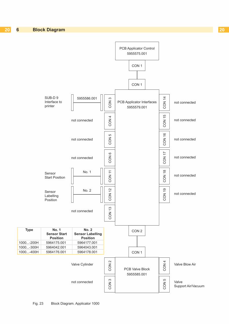
Fig. 23 Block Diagram. Applicator 1000
PCB Applicator Interfaces5955579.001
CON 2
CON 1
C
ON
14
C
ON
15
C
ON
16
C
ON
17
C
ON
18
C
ON
19
C
ON
3
CO
N 4
C
ON
5
CO
N 6
C
ON
11
C
ON
12
PCB Valve Block5955585.001
CON 1
C
ON
2
CO
N 3
C
ON
4
CO
N 5
PCB Applicator Control5955575.001
CON 1
not connected
not connected C
ON
13
not connected
not connected
not connected
not connected
not connected
not connected
not connected
Sensor Labelling Position
No. 2
Sensor Start Position
No. 1
not connected
SUB-D 9 Interface to printer
5955586.001
not connected
Valve Cylinder Valve Blow Air
Valve Support Air/Vacuum
Type No. 1 Sensor Start
Position
No. 2 Sensor Labelling
Position1000...-200H 5964175.001 5964177.0011000...-300H 5964042.001 5964043.0011000...-400H 5964176.001 5964178.001

20 217 Pneumatic Drawing
Fig. 24 Pneumatic Drawing Applicator 1000
Pos
.1
Mai
nten
ance
uni
t with
shu
t dow
n va
lve
Pos
.2
Valv
e bl
ock
Pos
.3
Thro
ttle
valv
e lif
t cyl
inde
r mov
e ou
tP
os.
4Th
rottl
e va
lve
lift c
ylin
der m
ove
inP
os.
5C
ylin
der
Pos
.6
Vacu
um G
ener
ator
Pos
.7
Thro
ttle
valv
e Va
cuum
Pos
.8
Thro
ttle
valv
e S
uppo
rt A
ir
Pos
. 1
Pos
. 2
Pos
. 3P
os. 4
Pos
. 5
Pos
. 6
Pos
. 7P
os. 8
Vacu
um
B
low
Air
Cyl
inde
r
Sen
sor 1
: Sta
rt P
ositi
onS
enso
r 2: L
abel
ling
Pos
ition
22 22
A
Address ..............................................2Adjustment........................................16Aufschlagsensor ...............................16
B
Block Diagram ..................................20Blow Tube ...........................................8
C
Controller ..........................................13cover ...................................................9Cover ................................................ 11Cylinder ............................................14
E
Energy track .....................................15Environment .......................................5Error ..................................................18
F
Function ..............................................8
G
general error .....................................16
I
Instructions .........................................4
L
Labeling position.................................8LED...................................................16
M
Maintenance Unit................................8Measurement....................................17
O
Overview.............................................6
P
Pad ...............................................8, 10PCB Applicator Control .....................13PCB Applicator Interfaces.................14PC-Extractor .....................................13Pneumatic...........................................8Pneumatic Drawing ..........................21Pressure ...........................................17Pressure Air ........................................8
S
Safety .................................................5Sensor ..........................................8, 15Slide Foil ........................................... 11Start Position ......................................8Status LED .......................................16
T
Tools .................................................10Tube .................................................10
V
Vacuum ...............................................8Vacuum Generator .............................8Valve .................................................12Valve Block .........................................8
8 Index