service manual - cat pumps
TRANSCRIPT
www.catpumps.com
Product Quality, Reliability and Support You Expect
SERVICE MANUAL67070 PLUNGER PUMP
PUMP MODELS INCLUDED67070
SERVICE MANUAL | 67070 Plunger Pump2 (763) 780-5440 | [email protected] | www.catpumps.com
Safety Symbols 2
General Safety Information & Symbols 3
Seal & Valve Kits 6
Service Intervals 6
Seal & Valve Kit Pump Diagram 7
Tools Needed 7
Servicing the Seals 8
Manifold and Seal Removal 8
Seal Reassembly 11
Plunger Disassembly 12
Plunger Reassembly 13
Inlet and Discharge Manifolds Reassembly 14
Servicing the Valves 16
Valve Disassembly 16
Valve Reassembly & Installation 18
Crankcase Component Inspection 20
Reference Information 22
Preventive Maintenance Schedule 22
Torque Chart 23
Discharge Manifold Torque Sequence 23
Valve Plug Cover Torque Sequence 23
Technical Bulletin Reference Chart 23
Diagnosis and Maintenance 24
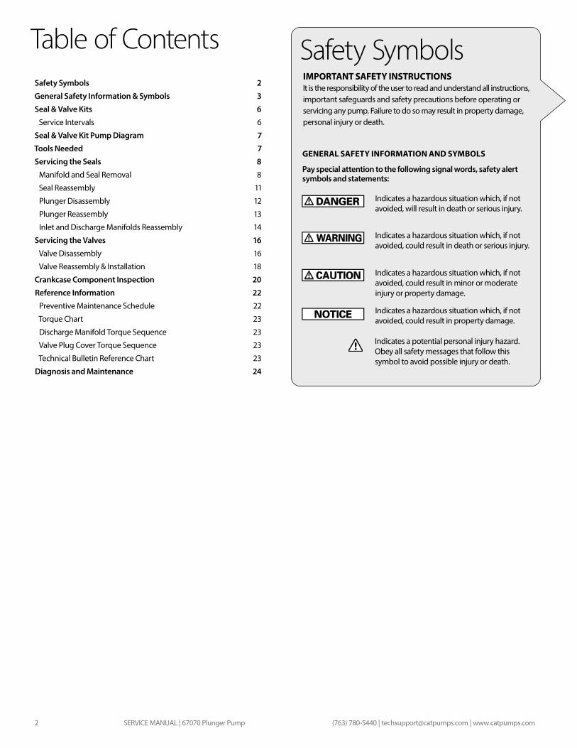
Table of ContentsIMPORTANT SAFETY INSTRUCTIONSIt is the responsibility of the user to read and understand all instructions, important safeguards and safety precautions before operating or servicing any pump. Failure to do so may result in property damage, personal injury or death.
GENERAL SAFETY INFORMATION AND SYMBOLS
Pay special attention to the following signal words, safety alert symbols and statements:
Safety Symbols
Indicates a potential personal injury hazard. Obey all safety messages that follow this symbol to avoid possible injury or death.
Indicates a hazardous situation which, if not avoided, could result in minor or moderate injury or property damage.
Indicates a hazardous situation which, if not avoided, could result in property damage.
Indicates a hazardous situation which, if not avoided, will result in death or serious injury.
Indicates a hazardous situation which, if not avoided, could result in death or serious injury.
SERVICE MANUAL | 67070 Plunger Pump 3(763) 780-5440 | [email protected] | www.catpumps.com
General Safety Information & Symbols
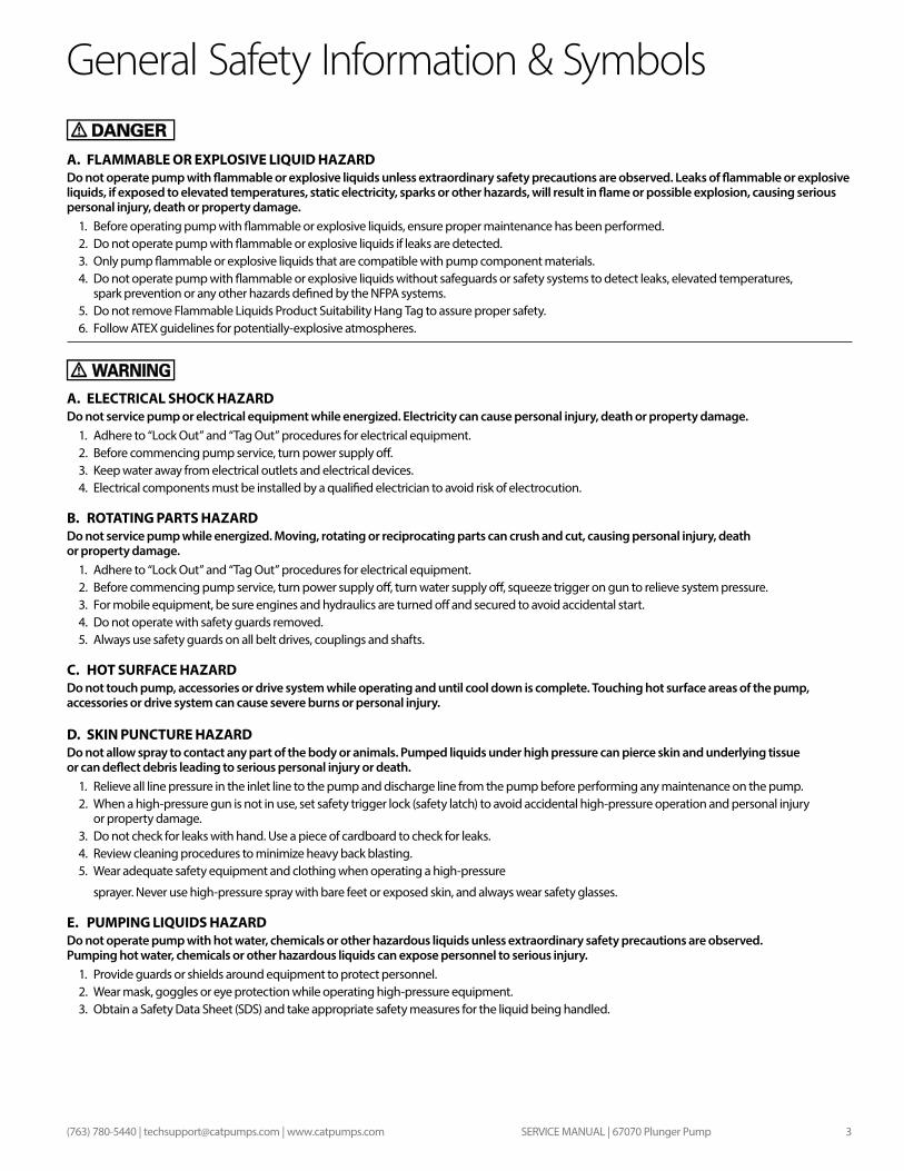
A. FLAMMABLE OR EXPLOSIVE LIQUID HAZARDDo not operate pump with flammable or explosive liquids unless extraordinary safety precautions are observed. Leaks of flammable or explosive liquids, if exposed to elevated temperatures, static electricity, sparks or other hazards, will result in flame or possible explosion, causing serious personal injury, death or property damage.
1. Before operating pump with flammable or explosive liquids, ensure proper maintenance has been performed.2. Do not operate pump with flammable or explosive liquids if leaks are detected.3. Only pump flammable or explosive liquids that are compatible with pump component materials.4. Do not operate pump with flammable or explosive liquids without safeguards or safety systems to detect leaks, elevated temperatures,
spark prevention or any other hazards defined by the NFPA systems.5. Do not remove Flammable Liquids Product Suitability Hang Tag to assure proper safety.6. Follow ATEX guidelines for potentially-explosive atmospheres.
A. ELECTRICAL SHOCK HAZARDDo not service pump or electrical equipment while energized. Electricity can cause personal injury, death or property damage.
1. Adhere to “Lock Out” and “Tag Out” procedures for electrical equipment.2. Before commencing pump service, turn power supply off. 3. Keep water away from electrical outlets and electrical devices.4. Electrical components must be installed by a qualified electrician to avoid risk of electrocution.
B. ROTATING PARTS HAZARDDo not service pump while energized. Moving, rotating or reciprocating parts can crush and cut, causing personal injury, death or property damage.
1. Adhere to “Lock Out” and “Tag Out” procedures for electrical equipment.2. Before commencing pump service, turn power supply off, turn water supply off, squeeze trigger on gun to relieve system pressure. 3. For mobile equipment, be sure engines and hydraulics are turned off and secured to avoid accidental start.4. Do not operate with safety guards removed.5. Always use safety guards on all belt drives, couplings and shafts.
C. HOT SURFACE HAZARDDo not touch pump, accessories or drive system while operating and until cool down is complete. Touching hot surface areas of the pump, accessories or drive system can cause severe burns or personal injury.
D. SKIN PUNCTURE HAZARDDo not allow spray to contact any part of the body or animals. Pumped liquids under high pressure can pierce skin and underlying tissue or can deflect debris leading to serious personal injury or death.
1. Relieve all line pressure in the inlet line to the pump and discharge line from the pump before performing any maintenance on the pump.2. When a high-pressure gun is not in use, set safety trigger lock (safety latch) to avoid accidental high-pressure operation and personal injury
or property damage.3. Do not check for leaks with hand. Use a piece of cardboard to check for leaks.4. Review cleaning procedures to minimize heavy back blasting.5. Wear adequate safety equipment and clothing when operating a high-pressure
sprayer. Never use high-pressure spray with bare feet or exposed skin, and always wear safety glasses.
E. PUMPING LIQUIDS HAZARDDo not operate pump with hot water, chemicals or other hazardous liquids unless extraordinary safety precautions are observed. Pumping hot water, chemicals or other hazardous liquids can expose personnel to serious injury.
1. Provide guards or shields around equipment to protect personnel.2. Wear mask, goggles or eye protection while operating high-pressure equipment.3. Obtain a Safety Data Sheet (SDS) and take appropriate safety measures for the liquid being handled.
SERVICE MANUAL | 67070 Plunger Pump4 (763) 780-5440 | [email protected] | www.catpumps.com
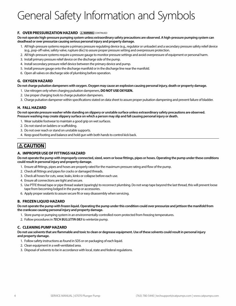
General Safety Information and SymbolsF. OVER PRESSURIZATION HAZARDDo not operate high-pressure pumping system unless extraordinary safety precautions are observed. A high-pressure pumping system can deadhead or over pressurize causing serious personal injury and property damage.
1. All high-pressure systems require a primary pressure regulating device (e.g., regulator or unloader) and a secondary pressure safety relief device (e.g., pop-off valve, safety valve, rupture disc) to assure proper pressure setting and overpressure protection.
2. All high-pressure systems require a pressure gauge to monitor pressure settings and avoid overpressure of equipment or personal harm.3. Install primary pressure relief device on the discharge side of the pump.4. Install secondary pressure relief device between the primary device and pump.5. Install pressure gauge onto the discharge manifold or in the discharge line near the manifold.6. Open all valves on discharge side of plumbing before operation.
G. OXYGEN HAZARDDo not charge pulsation dampeners with oxygen. Oxygen may cause an explosion causing personal injury, death or property damage.
1. Use nitrogen only when charging pulsation dampeners, DO NOT USE OXYGEN.2. Use proper charging tools to charge pulsation dampeners.3. Charge pulsation dampener within specifications stated on data sheet to assure proper pulsation dampening and prevent failure of bladder.
H. FALL HAZARDDo not operate pressure washer while standing on slippery or unstable surface unless extraordinary safety precautions are observed. Pressure washing may create slippery surface on which a person may slip and fall causing personal injury or death.
1. Wear suitable footwear to maintain a good grip on wet surfaces.2. Do not stand on ladders or scaffolding.3. Do not over reach or stand on unstable supports.4. Keep good footing and balance and hold gun with both hands to control kick back.
A. IMPROPER USE OF FITTINGS HAZARDDo not operate the pump with improperly-connected, sized, worn or loose fittings, pipes or hoses. Operating the pump under these conditions could result in personal injury and property damage.
1. Ensure all fittings, pipes and hoses are properly rated for the maximum pressure rating and flow of the pump.2. Check all fittings and pipes for cracks or damaged threads.3. Check all hoses for cuts, wear, leaks, kinks or collapse before each use.4. Ensure all connections are tight and secure.5. Use PTFE thread tape or pipe thread sealant (sparingly) to reconnect plumbing. Do not wrap tape beyond the last thread, this will prevent loose
tape from becoming lodged in the pump or accessories.6. Apply proper sealants to assure secure fit or easy disassembly when servicing.
B. FROZEN LIQUID HAZARDDo not operate the pump with frozen liquid. Operating the pump under this condition could over pressurize and jettison the manifold from the crankcase causing personal injury and property damage.
1. Store pump or pumping system in an environmentally-controlled room protected from freezing temperatures.2. Follow procedures in TECH BULLETIN 083 to winterize pump.
C. CLEANING PUMP HAZARDDo not use solvents that are flammable and toxic to clean or degrease equipment. Use of these solvents could result in personal injury and property damage.
1. Follow safety instructions as found in SDS or on packaging of each liquid.2. Clean equipment in a well-ventilated area.3. Disposal of solvents to be in accordance with local, state and federal regulations.
CONTINUED
SERVICE MANUAL | 67070 Plunger Pump 5(763) 780-5440 | [email protected] | www.catpumps.com
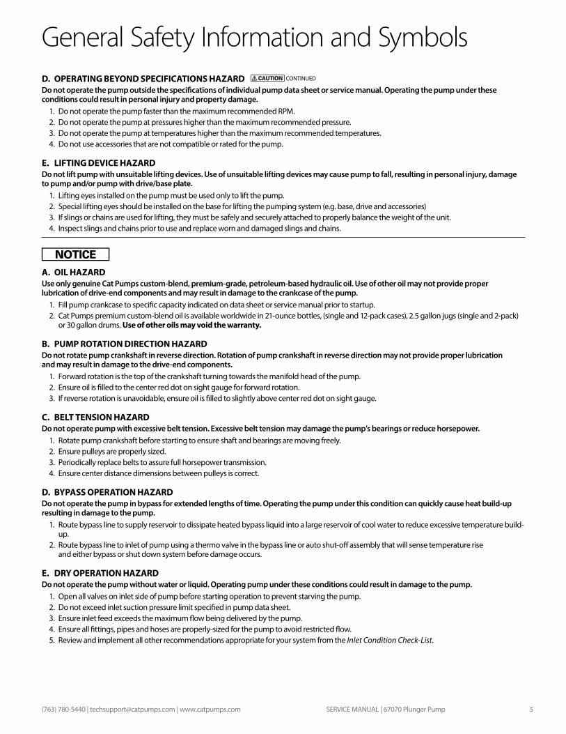
General Safety Information and SymbolsD. OPERATING BEYOND SPECIFICATIONS HAZARDDo not operate the pump outside the specifications of individual pump data sheet or service manual. Operating the pump under these conditions could result in personal injury and property damage.
1. Do not operate the pump faster than the maximum recommended RPM.2. Do not operate the pump at pressures higher than the maximum recommended pressure.3. Do not operate the pump at temperatures higher than the maximum recommended temperatures.4. Do not use accessories that are not compatible or rated for the pump.
E. LIFTING DEVICE HAZARDDo not lift pump with unsuitable lifting devices. Use of unsuitable lifting devices may cause pump to fall, resulting in personal injury, damage to pump and/or pump with drive/base plate.
1. Lifting eyes installed on the pump must be used only to lift the pump.2. Special lifting eyes should be installed on the base for lifting the pumping system (e.g. base, drive and accessories) 3. If slings or chains are used for lifting, they must be safely and securely attached to properly balance the weight of the unit.4. Inspect slings and chains prior to use and replace worn and damaged slings and chains.
A. OIL HAZARDUse only genuine Cat Pumps custom-blend, premium-grade, petroleum-based hydraulic oil. Use of other oil may not provide proper lubrication of drive-end components and may result in damage to the crankcase of the pump.
1. Fill pump crankcase to specific capacity indicated on data sheet or service manual prior to startup.2. Cat Pumps premium custom-blend oil is available worldwide in 21-ounce bottles, (single and 12-pack cases), 2.5 gallon jugs (single and 2-pack)
or 30 gallon drums. Use of other oils may void the warranty.
B. PUMP ROTATION DIRECTION HAZARDDo not rotate pump crankshaft in reverse direction. Rotation of pump crankshaft in reverse direction may not provide proper lubrication and may result in damage to the drive-end components.
1. Forward rotation is the top of the crankshaft turning towards the manifold head of the pump.2. Ensure oil is filled to the center red dot on sight gauge for forward rotation.3. If reverse rotation is unavoidable, ensure oil is filled to slightly above center red dot on sight gauge.
C. BELT TENSION HAZARDDo not operate pump with excessive belt tension. Excessive belt tension may damage the pump’s bearings or reduce horsepower.
1. Rotate pump crankshaft before starting to ensure shaft and bearings are moving freely.2. Ensure pulleys are properly sized.3. Periodically replace belts to assure full horsepower transmission.4. Ensure center distance dimensions between pulleys is correct.
D. BYPASS OPERATION HAZARDDo not operate the pump in bypass for extended lengths of time. Operating the pump under this condition can quickly cause heat build-up resulting in damage to the pump.
1. Route bypass line to supply reservoir to dissipate heated bypass liquid into a large reservoir of cool water to reduce excessive temperature build-up.
2. Route bypass line to inlet of pump using a thermo valve in the bypass line or auto shut-off assembly that will sense temperature rise and either bypass or shut down system before damage occurs.
E. DRY OPERATION HAZARDDo not operate the pump without water or liquid. Operating pump under these conditions could result in damage to the pump.
1. Open all valves on inlet side of pump before starting operation to prevent starving the pump.2. Do not exceed inlet suction pressure limit specified in pump data sheet.3. Ensure inlet feed exceeds the maximum flow being delivered by the pump.4. Ensure all fittings, pipes and hoses are properly-sized for the pump to avoid restricted flow. 5. Review and implement all other recommendations appropriate for your system from the Inlet Condition Check-List.
CONTINUED
SERVICE MANUAL | 67070 Plunger Pump6 (763) 780-5440 | [email protected] | www.catpumps.com
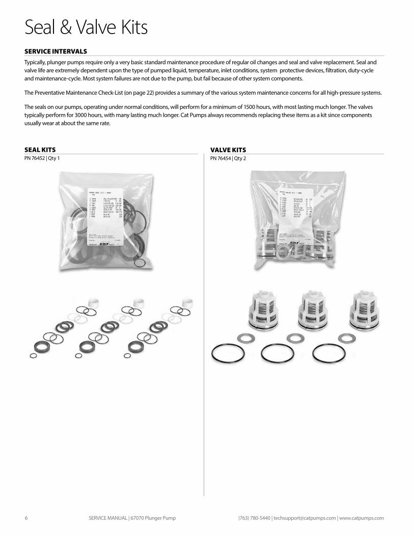
Seal & Valve Kits SERVICE INTERVALS Typically, plunger pumps require only a very basic standard maintenance procedure of regular oil changes and seal and valve replacement. Seal and valve life are extremely dependent upon the type of pumped liquid, temperature, inlet conditions, system protective devices, filtration, duty-cycle and maintenance-cycle. Most system failures are not due to the pump, but fail because of other system components.
The Preventative Maintenance Check-List (on page 22) provides a summary of the various system maintenance concerns for all high-pressure systems.
The seals on our pumps, operating under normal conditions, will perform for a minimum of 1500 hours, with most lasting much longer. The valves typically perform for 3000 hours, with many lasting much longer. Cat Pumps always recommends replacing these items as a kit since components usually wear at about the same rate.
SEAL KITS PN 76452 | Qty 1
VALVE KITSPN 76454 | Qty 2
SERVICE MANUAL | 67070 Plunger Pump 7(763) 780-5440 | [email protected] | www.catpumps.com
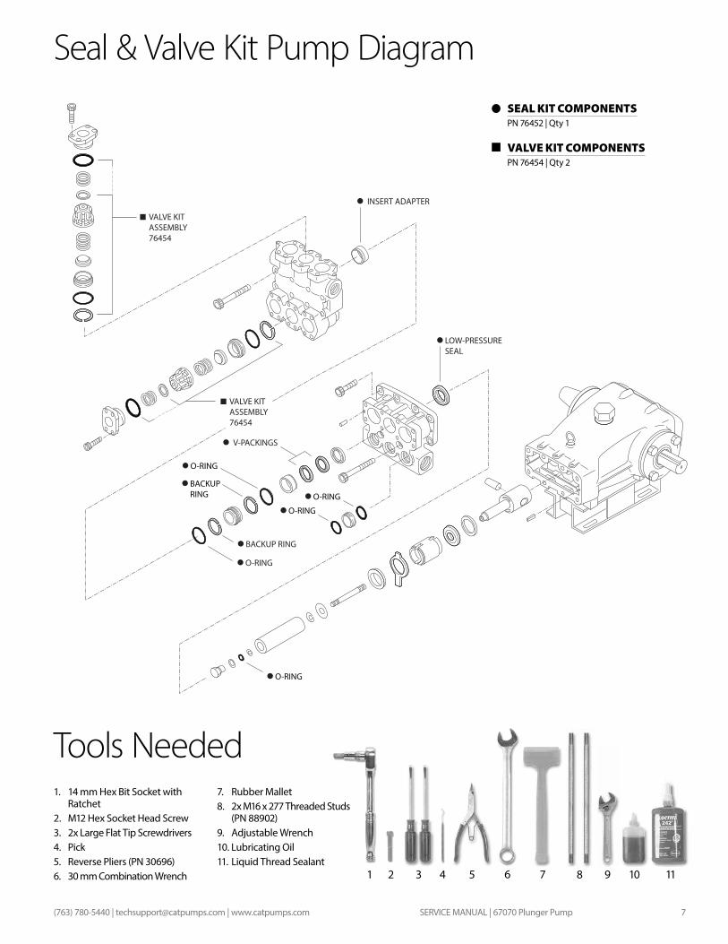
VALVE KIT ASSEMBLY 76454
O-RING
O-RING
O-RING
BACKUPRING O-RING
V-PACKINGS
INSERT ADAPTER
LOW-PRESSURESEAL
BACKUP RING
O-RING
VALVE KIT ASSEMBLY 76454
Tools Needed1. 14 mm Hex Bit Socket with
Ratchet2. M12 Hex Socket Head Screw 3. 2x Large Flat Tip Screwdrivers4. Pick5. Reverse Pliers (PN 30696)6. 30 mm Combination Wrench
7. Rubber Mallet8. 2x M16 x 277 Threaded Studs
(PN 88902)9. Adjustable Wrench10. Lubricating Oil11. Liquid Thread Sealant
Seal & Valve Kit Pump Diagram
VALVE KIT COMPONENTSPN 76454 | Qty 2
32 4 5 11109871
SEAL KIT COMPONENTS PN 76452 | Qty 1
6
SERVICE MANUAL | 67070 Plunger Pump8 (763) 780-5440 | [email protected] | www.catpumps.com
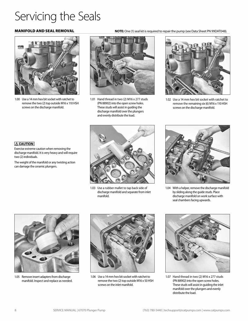
Servicing the SealsMANIFOLD AND SEAL REMOVAL
1.03 Use a rubber mallet to tap back side of discharge manifold and separate from inlet manifold.
1.05 Remove insert adapters from discharge manifold. Inspect and replace as needed.
1.04 With a helper, remove the discharge manifold by sliding along the guide studs. Place discharge manifold on work surface with seal chambers facing upwards.
1.00 Use a 14 mm hex bit socket with ratchet to remove the two (2) top outside M16 x 110 HSH screws on the discharge manifold.
1.01 Hand thread in two (2) M16 x 277 studs (PN 88902) into the open screw holes. These studs will assist in guiding the discharge manifold over the plungers and evenly distribute the load.
1.02 Use a 14 mm hex bit socket with ratchet to remove the remaining six (6) M16 x 110 HSH screws on the discharge manifold.
1.06 Use a 14 mm hex bit socket with ratchet to remove the two (2) top outside M16 x 50 HSH screws on the inlet manifold.
1.07 Hand thread in two (2) M16 x 277 studs (PN 88902) into the open screw holes. These studs will assist in guiding the inlet manifold over the plungers and evenly distribute the load.
Exercise extreme caution when removing the discharge manifold. It is very heavy and will require two (2) individuals.
The weight of the manifold or any twisting action can damage the ceramic plungers.
NOTE: One (1) seal kit is required to repair the pump (see Data Sheet PN 99DAT048).
SERVICE MANUAL | 67070 Plunger Pump 9(763) 780-5440 | [email protected] | www.catpumps.com
Servicing the SealsMANIFOLD AND SEAL REMOVAL
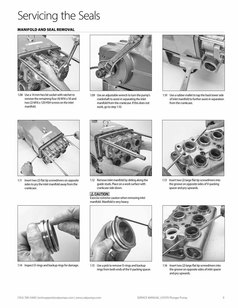
1.08 Use a 14 mm hex bit socket with ratchet to remove the remaining four (4) M16 x 50 and two (2) M16 x 120 HSH screws on the inlet manifold.
1.09 Use an adjustable wrench to turn the pump’s crankshaft to assist in separating the inlet manifold from the crankcase. If this does not work, go to step 1.10.
1.12 Remove inlet manifold by sliding along the guide studs. Place on a work surface with crankcase side down.
Exercise extreme caution when removing inlet manifold. Manifold is very heavy.
1.15 Use a pick to remove O-rings and backup rings from both ends of the V-packing spacer.
1.10 Use a rubber mallet to tap the back lower side of inlet manifold to further assist in separation from the crankcase.
1.13 Insert two (2) large flat tip screwdrivers into the groove on opposite sides of V-packing spacer and pry upwards.
1.16 Insert two (2) large flat tip screwdrivers into the groove on opposite sides of inlet spacer and pry upwards.
1.11 Insert two (2) flat tip screwdrivers on opposite sides to pry the inlet manifold away from the crankcase.
1.14 Inspect O-rings and backup rings for damage.
SERVICE MANUAL | 67070 Plunger Pump10 (763) 780-5440 | [email protected] | www.catpumps.com
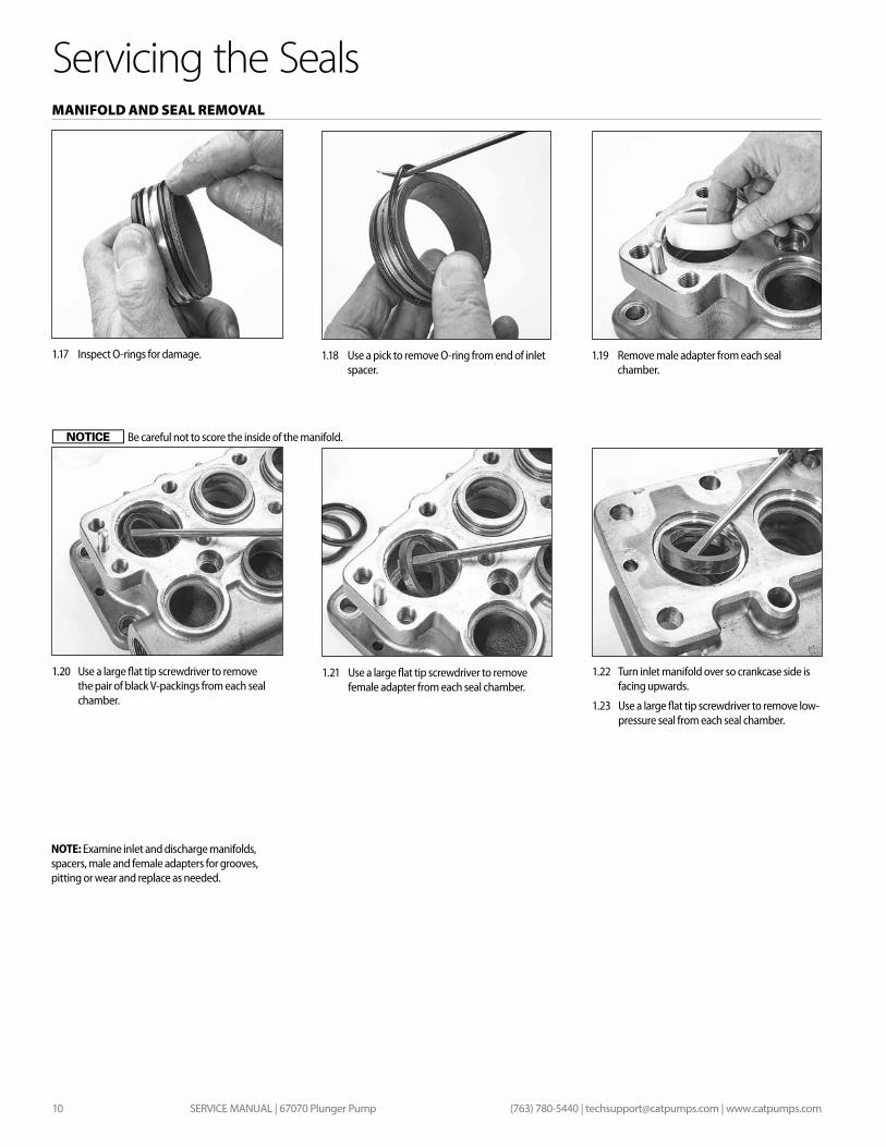
1.19 Remove male adapter from each seal chamber.
1.21 Use a large flat tip screwdriver to remove female adapter from each seal chamber.
1.18 Use a pick to remove O-ring from end of inlet spacer.
Servicing the Seals
1.17 Inspect O-rings for damage.
1.20 Use a large flat tip screwdriver to remove the pair of black V-packings from each seal chamber.
MANIFOLD AND SEAL REMOVAL
NOTE: Examine inlet and discharge manifolds, spacers, male and female adapters for grooves, pitting or wear and replace as needed.
1.22 Turn inlet manifold over so crankcase side is facing upwards.
1.23 Use a large flat tip screwdriver to remove low-pressure seal from each seal chamber.
Be careful not to score the inside of the manifold.
SERVICE MANUAL | 67070 Plunger Pump 11(763) 780-5440 | [email protected] | www.catpumps.com
SEAL REASSEMBLY
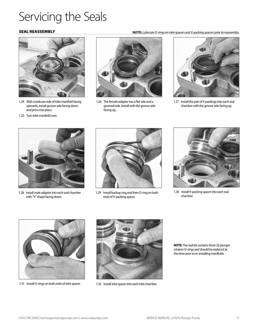
1.26 The female adapter has a flat side and a grooved side. Install with the groove side facing up.
1.29 Install backup ring and then O-ring on both ends of V-packing spacer.
1.24 With crankcase side of inlet manifold facing upwards, install groove side facing down and press into place.
1.25 Turn inlet manifold over.
1.27 Install the pair of V-packings into each seal chamber with the groove side facing up.
1.28 Install male adapter into each seal chamber with “V” shape facing down.
Servicing the Seals
1.32 Install inlet spacer into each inlet chamber.
1.30 Install V-packing spacer into each seal chamber.
1.31 Install O-rings on both ends of inlet spacer.
NOTE: The seal kit contains three (3) plunger retainer O-rings and should be replaced at this time prior to re-installing manifolds.
NOTE: Lubricate O-rings on inlet spacers and V-packing spacers prior to reassembly.
SERVICE MANUAL | 67070 Plunger Pump12 (763) 780-5440 | [email protected] | www.catpumps.com
PLUNGER DISASSEMBLY
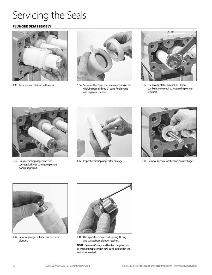
1.33 Remove seal retainers with wicks. 1.34 Separate the 2-piece retainer and remove the wick. Inspect all three (3) parts for damage and replace as needed.
Servicing the Seals
1.35 Use an adjustable wrench or 30 mm combination wrench to loosen the plunger retainers.
1.38 Remove keyhole washer and barrier slinger.1.36 Grasp ceramic plunger and turn counterclockwise to remove plunger from plunger rod.
1.39 Remove plunger retainer from ceramic plunger.
1.37 Inspect ceramic plungers for damage.
1.40 Use a pick to remove backup ring, O-ring and gasket from plunger retainer.
NOTE: Examine O-rings and backup rings for cuts or wear and replace with new parts as found in the seal kit as needed.
SERVICE MANUAL | 67070 Plunger Pump 13(763) 780-5440 | [email protected] | www.catpumps.com
Servicing the Seals
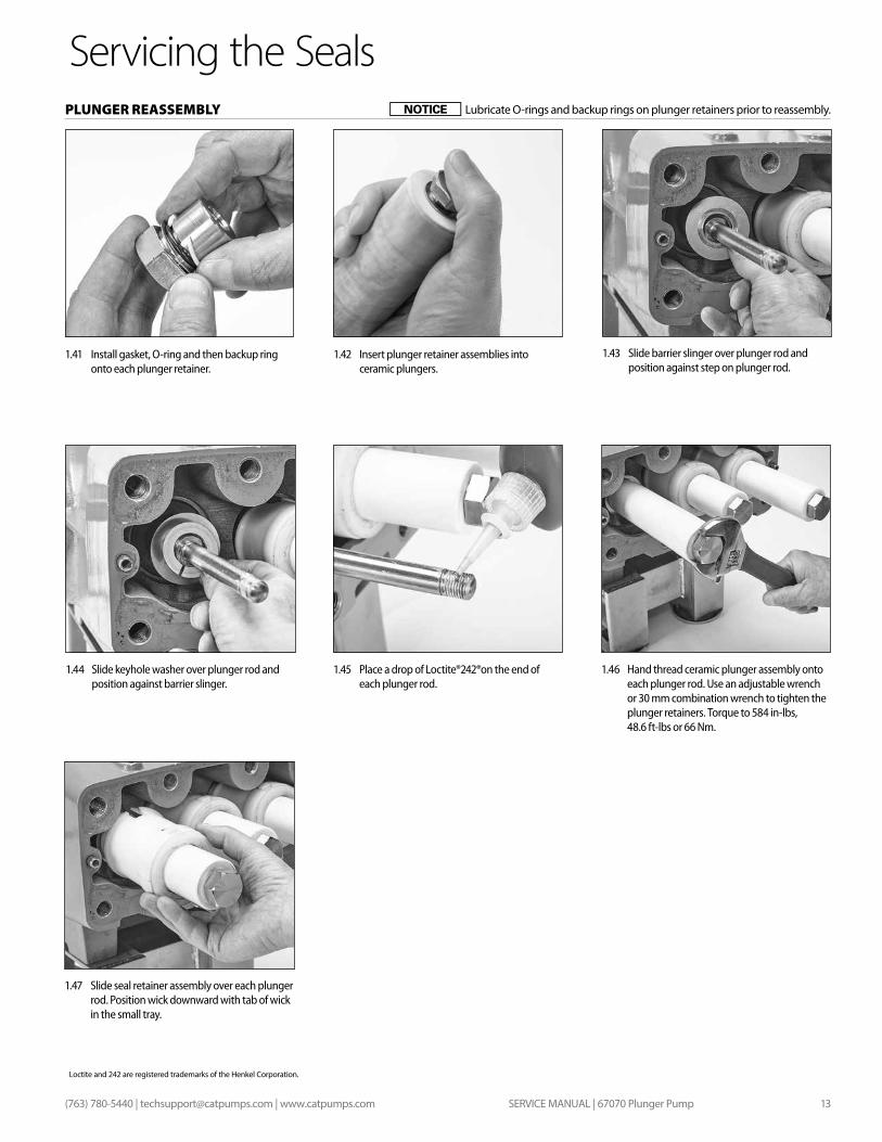
1.43 Slide barrier slinger over plunger rod and position against step on plunger rod.
1.46 Hand thread ceramic plunger assembly onto each plunger rod. Use an adjustable wrench or 30 mm combination wrench to tighten the plunger retainers. Torque to 584 in-lbs, 48.6 ft-lbs or 66 Nm.
1.44 Slide keyhole washer over plunger rod and position against barrier slinger.
1.47 Slide seal retainer assembly over each plunger rod. Position wick downward with tab of wick in the small tray.
1.45 Place a drop of Loctite®242®on the end of each plunger rod.
1.41 Install gasket, O-ring and then backup ring onto each plunger retainer.
1.42 Insert plunger retainer assemblies into ceramic plungers.
Loctite and 242 are registered trademarks of the Henkel Corporation.
PLUNGER REASSEMBLY Lubricate O-rings and backup rings on plunger retainers prior to reassembly.
SERVICE MANUAL | 67070 Plunger Pump14 (763) 780-5440 | [email protected] | www.catpumps.com
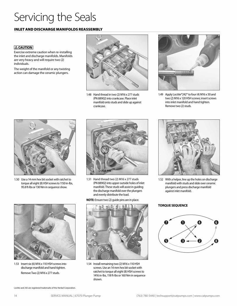
1.50 Use a 14 mm hex bit socket with ratchet to torque all eight (8) HSH screws to 1150 in-lbs, 95.8 ft-lbs or 130 Nm in sequence show.
1.49 Apply Loctite®242® to four (4) M16 x 50 and two (2) M16 x 120 HSH screws; insert screws into inlet manifold and hand tighten. Remove two (2) studs.
1.52 With a helper, line up the holes on discharge manifold with studs and slide over ceramic plungers and press discharge manifold against inlet manifold.
1.51 Hand thread two (2) M16 x 277 studs (PN 88902) into upper outside holes of inlet manifold. These studs will assist in guiding the discharge manifold over the plungers and evenly distribute the load.
NOTE: Ensure two (2) guide pins are in place.
1.53 Insert six (6) M16 x 110 HSH screws into discharge manifold and hand tighten.
Remove Two (2) M16 x 277 studs.
1.54 Install remaining two (2) M16 x 110 HSH screws. Use an 14 mm hex bit socket with ratchet to torque all eight (8) HSH screws to 1416 in-lbs, 118 ft-lbs or 160 Nm in sequence shown.
1.48 Hand thread in two (2) M16 x 277 studs (PN 88902) into crankcase. Place inlet manifold onto studs and slide up against crankcase.
Servicing the SealsINLET AND DISCHARGE MANIFOLDS REASSEMBLY
TORQUE SEQUENCE
Exercise extreme caution when re-installing the inlet and discharge manifolds. Manifolds are very heavy and will require two (2) individuals.
The weight of the manifold or any twisting action can damage the ceramic plungers.
Loctite and 242 are registered trademarks of the Henkel Corporation.
GUIDE PIN

SERVICE MANUAL | 67070 Plunger Pump 15(763) 780-5440 | [email protected] | www.catpumps.com
SERVICE MANUAL | 67070 Plunger Pump16 (763) 780-5440 | [email protected] | www.catpumps.com
Servicing the ValvesVALVE DISASSEMBLY
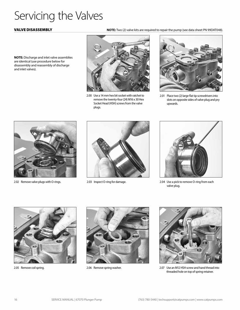
2.00 Use a 14 mm hex bit socket with ratchet to remove the twenty-four (24) M16 x 30 Hex Socket Head (HSH) screws from the valve plugs.
2.01 Place two (2) large flat tip screwdrivers into slots on opposite sides of valve plug and pry upwards.
2.02 Remove valve plugs with O-rings.
2.05 Remove coil spring. 2.06 Remove spring washer. 2.07 Use an M12 HSH screw and hand thread into threaded hole on top of spring retainer.
2.03 Inspect O-ring for damage. 2.04 Use a pick to remove O-ring from each valve plug.
NOTE: Two (2) valve kits are required to repair the pump (see data sheet PN 99DAT048).
NOTE: Discharge and inlet valve assemblies are identical (use procedure below for disassembly and reassembly of discharge and inlet valves).
SERVICE MANUAL | 67070 Plunger Pump 17(763) 780-5440 | [email protected] | www.catpumps.com
Servicing the ValvesVALVE DISASSEMBLY
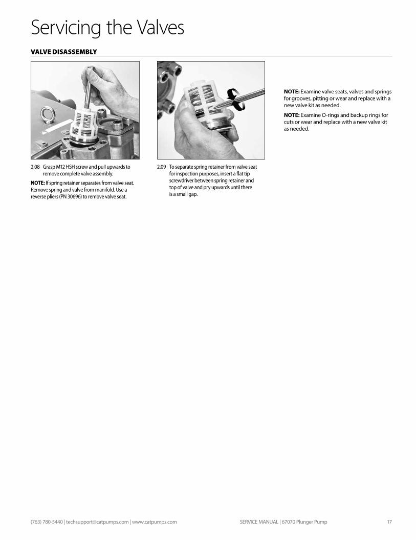
2.09 To separate spring retainer from valve seat for inspection purposes, insert a flat tip screwdriver between spring retainer and top of valve and pry upwards until there is a small gap.
2.08 Grasp M12 HSH screw and pull upwards to remove complete valve assembly.
NOTE: If spring retainer separates from valve seat. Remove spring and valve from manifold. Use a reverse pliers (PN 30696) to remove valve seat.
NOTE: Examine valve seats, valves and springs for grooves, pitting or wear and replace with a new valve kit as needed.
NOTE: Examine O-rings and backup rings for cuts or wear and replace with a new valve kit as needed.
SERVICE MANUAL | 67070 Plunger Pump18 (763) 780-5440 | [email protected] | www.catpumps.com
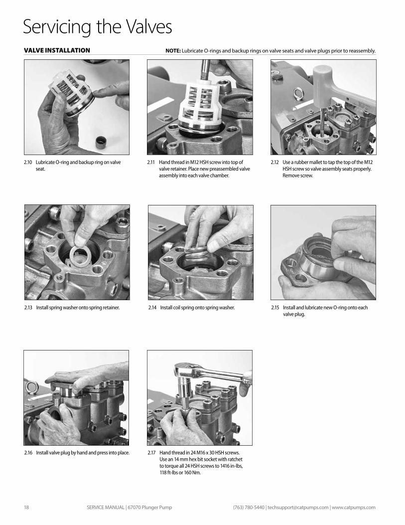
Servicing the ValvesVALVE INSTALLATION
2.10 Lubricate O-ring and backup ring on valve seat.
2.11 Hand thread in M12 HSH screw into top of valve retainer. Place new preassembled valve assembly into each valve chamber.
2.12 Use a rubber mallet to tap the top of the M12 HSH screw so valve assembly seats properly. Remove screw.
2.13 Install spring washer onto spring retainer. 2.14 Install coil spring onto spring washer. 2.15 Install and lubricate new O-ring onto each valve plug.
NOTE: Lubricate O-rings and backup rings on valve seats and valve plugs prior to reassembly.
2.17 Hand thread in 24 M16 x 30 HSH screws. Use an 14 mm hex bit socket with ratchet to torque all 24 HSH screws to 1416 in-lbs, 118 ft-lbs or 160 Nm.
2.16 Install valve plug by hand and press into place.

SERVICE MANUAL | 67070 Plunger Pump 19(763) 780-5440 | [email protected] | www.catpumps.com
SERVICE MANUAL | 67070 Plunger Pump20 (763) 780-5440 | [email protected] | www.catpumps.com
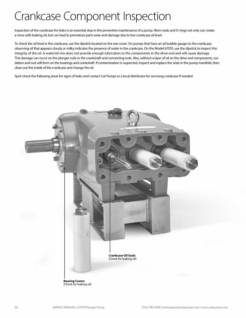
Bearing Covers (Check for leaking oil)
Crankcase Oil Seals (Check for leaking oil)
Inspection of the crankcase for leaks is an essential step in the preventive maintenance of a pump. Worn seals and O-rings not only can create a mess with leaking oil, but can lead to premature parts wear and damage due to low crankcase oil level.
To check the oil level in the crankcase, use the dipstick located on the rear cover. On pumps that have an oil bubble gauge on the crankcase, observing oil that appears cloudy or milky indicates the presence of water in the crankcase. On the Model 67070, use the dipstick to inspect the integrity of the oil. A water/oil mix does not provide enough lubrication to the components in the drive end and will cause damage. This damage can occur on the plunger rods or the crankshaft and connecting rods. Also, without a layer of oil on the drive end components, oxi-dation and rust will form on the bearings and crankshaft. If contamination is suspected, inspect and replace the seals in the pump manifold, then clean out the inside of the crankcase and change the oil.
Spot-check the following areas for signs of leaks and contact Cat Pumps or a local distributor for servicing crankcase if needed.
Crankcase Component Inspection
SERVICE MANUAL | 67070 Plunger Pump 21(763) 780-5440 | [email protected] | www.catpumps.com
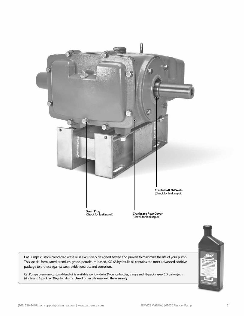
Crankshaft Oil Seals (Check for leaking oil)
Drain Plug (Check for leaking oil) Crankcase Rear Cover
(Check for leaking oil)
Cat Pumps custom blend crankcase oil is exclusively designed, tested and proven to maximize the life of your pump. This special formulated premium-grade, petroleum-based, ISO 68 hydraulic oil contains the most advanced additive package to protect against wear, oxidation, rust and corrosion.
Cat Pumps premium custom-blend oil is available worldwide in 21-ounce bottles, (single and 12-pack cases), 2.5 gallon jugs (single and 2-pack) or 30 gallon drums. Use of other oils may void the warranty.
SERVICE MANUAL | 67070 Plunger Pump22 (763) 780-5440 | [email protected] | www.catpumps.com
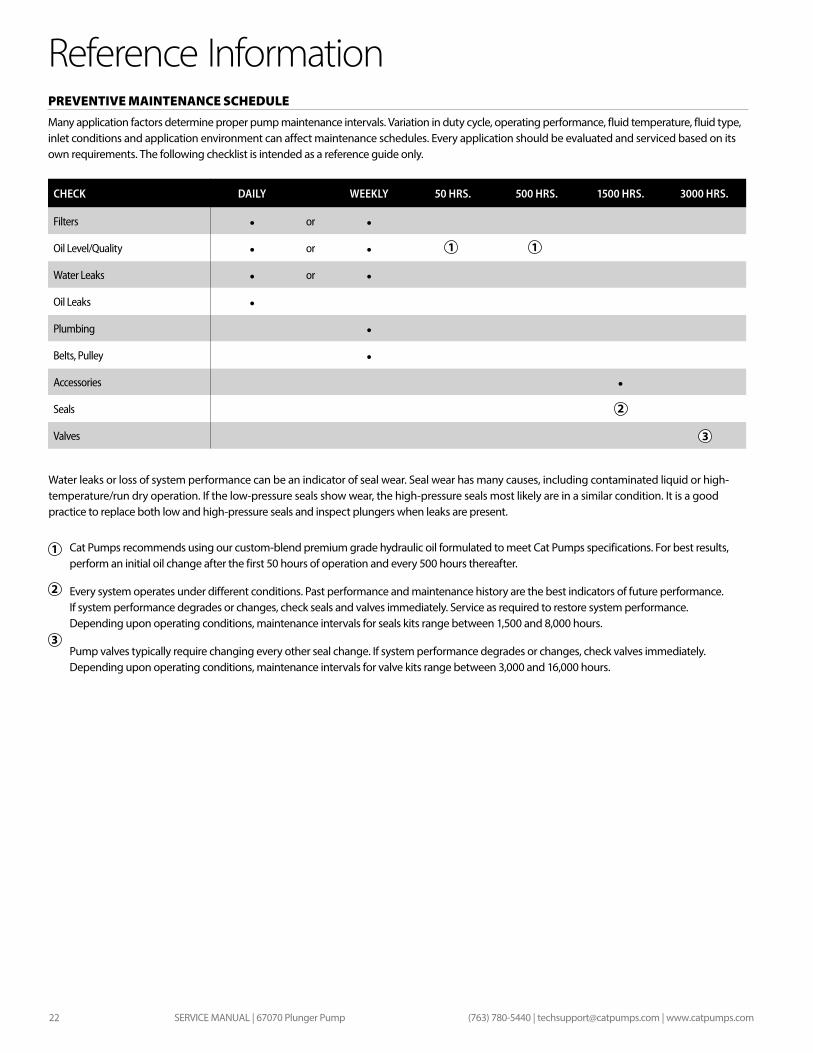
Reference InformationPREVENTIVE MAINTENANCE SCHEDULE Many application factors determine proper pump maintenance intervals. Variation in duty cycle, operating performance, fluid temperature, fluid type, inlet conditions and application environment can affect maintenance schedules. Every application should be evaluated and serviced based on its own requirements. The following checklist is intended as a reference guide only.
CHECK DAILY WEEKLY 50 HRS. 500 HRS. 1500 HRS. 3000 HRS.
Filters • or •Oil Level/Quality • or •Water Leaks • or •Oil Leaks •Plumbing •Belts, Pulley •Accessories •Seals
Valves
1 1
2
3
Cat Pumps recommends using our custom-blend premium grade hydraulic oil formulated to meet Cat Pumps specifications. For best results, perform an initial oil change after the first 50 hours of operation and every 500 hours thereafter.
Every system operates under different conditions. Past performance and maintenance history are the best indicators of future performance. If system performance degrades or changes, check seals and valves immediately. Service as required to restore system performance. Depending upon operating conditions, maintenance intervals for seals kits range between 1,500 and 8,000 hours.
Pump valves typically require changing every other seal change. If system performance degrades or changes, check valves immediately. Depending upon operating conditions, maintenance intervals for valve kits range between 3,000 and 16,000 hours.
1
2
3
Water leaks or loss of system performance can be an indicator of seal wear. Seal wear has many causes, including contaminated liquid or high- temperature/run dry operation. If the low-pressure seals show wear, the high-pressure seals most likely are in a similar condition. It is a good practice to replace both low and high-pressure seals and inspect plungers when leaks are present.
SERVICE MANUAL | 67070 Plunger Pump 23(763) 780-5440 | [email protected] | www.catpumps.com
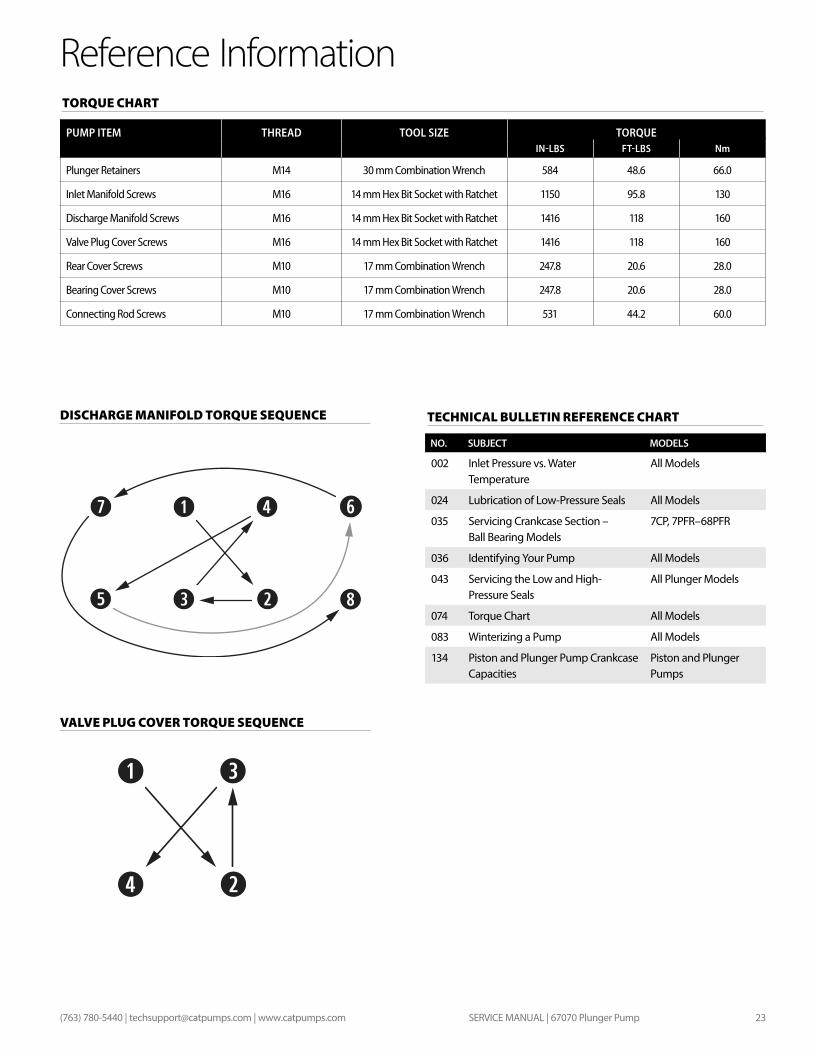
Reference InformationTORQUE CHART
PUMP ITEM THREAD TOOL SIZE TORQUEIN-LBS FT-LBS Nm
Plunger Retainers M14 30 mm Combination Wrench 584 48.6 66.0
Inlet Manifold Screws M16 14 mm Hex Bit Socket with Ratchet 1150 95.8 130
Discharge Manifold Screws M16 14 mm Hex Bit Socket with Ratchet 1416 118 160
Valve Plug Cover Screws M16 14 mm Hex Bit Socket with Ratchet 1416 118 160
Rear Cover Screws M10 17 mm Combination Wrench 247.8 20.6 28.0
Bearing Cover Screws M10 17 mm Combination Wrench 247.8 20.6 28.0
Connecting Rod Screws M10 17 mm Combination Wrench 531 44.2 60.0
TECHNICAL BULLETIN REFERENCE CHART
NO. SUBJECT MODELS
002 Inlet Pressure vs. Water Temperature
All Models
024 Lubrication of Low-Pressure Seals All Models
035 Servicing Crankcase Section – Ball Bearing Models
7CP, 7PFR–68PFR
036 Identifying Your Pump All Models
043 Servicing the Low and High- Pressure Seals
All Plunger Models
074 Torque Chart All Models
083 Winterizing a Pump All Models
134 Piston and Plunger Pump Crankcase Capacities
Piston and Plunger Pumps
DISCHARGE MANIFOLD TORQUE SEQUENCE
VALVE PLUG COVER TORQUE SEQUENCE
PN 99MAN006 Rev A 4/21
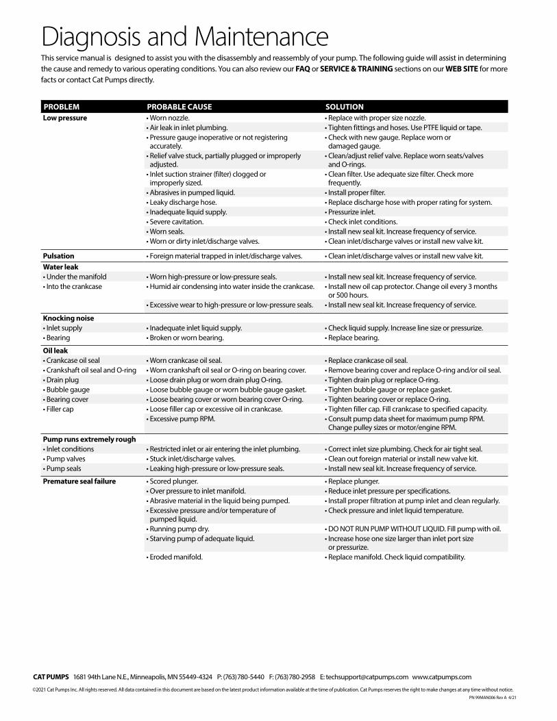
PROBLEM PROBABLE CAUSE SOLUTIONLow pressure • Worn nozzle. • Replace with proper size nozzle.
• Air leak in inlet plumbing. • Tighten fittings and hoses. Use PTFE liquid or tape.• Pressure gauge inoperative or not registering
accurately.• Check with new gauge. Replace worn or
damaged gauge.• Relief valve stuck, partially plugged or improperly
adjusted.• Clean/adjust relief valve. Replace worn seats/valves
and O-rings.• Inlet suction strainer (filter) clogged or
improperly sized.• Clean filter. Use adequate size filter. Check more
frequently.• Abrasives in pumped liquid. • Install proper filter.• Leaky discharge hose. • Replace discharge hose with proper rating for system.• Inadequate liquid supply. • Pressurize inlet. • Severe cavitation. • Check inlet conditions.• Worn seals. • Install new seal kit. Increase frequency of service.• Worn or dirty inlet/discharge valves. • Clean inlet/discharge valves or install new valve kit.
Pulsation • Foreign material trapped in inlet/discharge valves. • Clean inlet/discharge valves or install new valve kit.Water leak• Under the manifold • Worn high-pressure or low-pressure seals. • Install new seal kit. Increase frequency of service.• Into the crankcase • Humid air condensing into water inside the crankcase. • Install new oil cap protector. Change oil every 3 months
or 500 hours.• Excessive wear to high-pressure or low-pressure seals. • Install new seal kit. Increase frequency of service.
Knocking noise• Inlet supply • Inadequate inlet liquid supply. • Check liquid supply. Increase line size or pressurize.• Bearing • Broken or worn bearing. • Replace bearing.
Oil leak• Crankcase oil seal • Worn crankcase oil seal. • Replace crankcase oil seal.• Crankshaft oil seal and O-ring • Worn crankshaft oil seal or O-ring on bearing cover. • Remove bearing cover and replace O-ring and/or oil seal.• Drain plug • Loose drain plug or worn drain plug O-ring. • Tighten drain plug or replace O-ring.• Bubble gauge • Loose bubble gauge or worn bubble gauge gasket. • Tighten bubble gauge or replace gasket.• Bearing cover • Loose bearing cover or worn bearing cover O-ring. • Tighten bearing cover or replace O-ring.• Filler cap • Loose filler cap or excessive oil in crankcase. • Tighten filler cap. Fill crankcase to specified capacity.
• Excessive pump RPM. • Consult pump data sheet for maximum pump RPM. Change pulley sizes or motor/engine RPM.
Pump runs extremely rough• Inlet conditions • Restricted inlet or air entering the inlet plumbing. • Correct inlet size plumbing. Check for air tight seal.• Pump valves • Stuck inlet/discharge valves. • Clean out foreign material or install new valve kit.• Pump seals • Leaking high-pressure or low-pressure seals. • Install new seal kit. Increase frequency of service.
Premature seal failure • Scored plunger. • Replace plunger.• Over pressure to inlet manifold. • Reduce inlet pressure per specifications.• Abrasive material in the liquid being pumped. • Install proper filtration at pump inlet and clean regularly.• Excessive pressure and/or temperature of
pumped liquid.• Check pressure and inlet liquid temperature.
• Running pump dry. • DO NOT RUN PUMP WITHOUT LIQUID. Fill pump with oil.• Starving pump of adequate liquid. • Increase hose one size larger than inlet port size
or pressurize.• Eroded manifold. • Replace manifold. Check liquid compatibility.
Diagnosis and MaintenanceThis service manual is designed to assist you with the disassembly and reassembly of your pump. The following guide will assist in determining the cause and remedy to various operating conditions. You can also review our FAQ or SERVICE & TRAINING sections on our WEB SITE for more facts or contact Cat Pumps directly.
CAT PUMPS 1681 94th Lane N.E., Minneapolis, MN 55449-4324 P: (763) 780-5440 F: (763) 780-2958 E: [email protected] www.catpumps.com
©2021 Cat Pumps Inc. All rights reserved. All data contained in this document are based on the latest product information available at the time of publication. Cat Pumps reserves the right to make changes at any time without notice.