service manual europump international · service manual europump international 9.taking the lpg...
TRANSCRIPT

Service Manual EUROPUMP INTERNATIONAL
INDEX Page No
1. INFORMATIONS FOR CUSTOMERS 11.1 Pictograms and Terms Used in the Manual 11.2 Important Notices 2
2. SAFETY OF DISPENSER OPERATION 32.1 First Aid 3
3. DENOTATION OF THE LPG DISPENSER 4
4. OVERAL VIEW AND DESCRIPTIONS OF DISPENSERS 5
5. TRANSPORTATION 115.1 Loading and transportation5.2 Unloading5.3 Storage of the LPG dispenser
6. INSTALLATION AND TAKING THE LPG DISPENSER INTO SERVICE 116.1 Cleaning of pipes 126.2 Execution of Foundation 136.3 Shear valve / break point 136.4 Connection of the LPG dispenser to the suction and return line 136.5 LPG Dispenser Pump Switch 136.6 Emergency stop button 136.7 Gas Sensor 14
6.8 Lightining Protection 146.9 First Operation Of Dispenser 146.10 Refuelling of Cars 176.11 Principles of Operation and Maintenance of Break-Off Safety Valves 17
7. MAINTENANCE 187.1 Remarks relating operation 187.2 Filters 197.3 Greasing of rotary parts 197.4 Checking of hydraulic connections and electrical devices 197.5 Pipeline of liquefied and gaseous phases 197.6 Warranty and Complaints 19
8. ASSEMBLY 198.1 Anchoring the dispenser 198.2 Locking the counter 198.3 Mounting the columns 19
9. DISASSEMBLY 199.1 Opening the hydraulic housing 199.2 Opening of Counter Enclosure 209.3 Opening the columns 20
10. SERVICE MANUAL OF ELECTRONIC 21
10.1. SETTING OF PARAMETERS 22
10.2. DESCRIPTION OF PROGRAMMABLE FUNCTIONS 24
10.2.1. PUMP MENU 25
10.2.2. ADMINISTRATOR MENU 28
10.2.3. SERVICE MENU 30
i
Service Manual EUROPUMP INTERNATIONAL
10.3. GENERAL COMPUTER CONNECTION 36
10.4. DESCRIPTION OF DISPLAYED ERRORS 37
11. TECHNICAL DATA 39
12. BREAKDOWN REPAIRS 40
13. CONTACT US 61
DRAWING LIST
Drawing 1. CE Mark 2Drawing 2. Denotation of LPG dispenser 4Drawing 3. Overal View and Decriptions 5Drawing 4. Sample Station Establisment 15Drawing 5. Configurations and Overall Dimensions 41Drawing 6. Classification of hazardous areas 47Drawing 7. Connection Diagram 52Drawing 8. Hydraulic connections of the dispenser at the filling station 54Drawing 9. Hydraulic system Diagram 55Drawing 10. Foundation of the LPG dispensers 58
i
Service Manual EUROPUMP INTERNATIONAL
1. INFORMATIONS FOR CUSTOMERS
This service manual is designed for all customers and users of liquefied gas propane-butane dispensers series EUROSTAR.
As EUROPUMP INTERNATIONAL we recommend to become familiar with the presentmanual before proceeding to installation and use of this LPG dispenser.
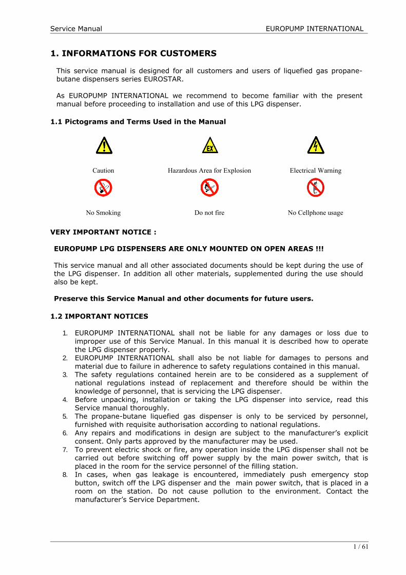
1.1 Pictograms and Terms Used in the Manual
Caution Hazardous Area for Explosion Electrical Warning
No Smoking Do not fire No Cellphone usage
VERY IMPORTANT NOTICE :
EUROPUMP LPG DISPENSERS ARE ONLY MOUNTED ON OPEN AREAS !!!
This service manual and all other associated documents should be kept during the use ofthe LPG dispenser. In addition all other materials, supplemented during the use shouldalso be kept.
Preserve this Service Manual and other documents for future users.
1.2 IMPORTANT NOTICES
1. EUROPUMP INTERNATIONAL shall not be liable for any damages or loss due toimproper use of this Service Manual. In this manual it is described how to operatethe LPG dispenser properly.
2. EUROPUMP INTERNATIONAL shall also be not liable for damages to persons andmaterial due to failure in adherence to safety regulations contained in this manual.
3. The safety regulations contained herein are to be considered as a supplement ofnational regulations instead of replacement and therefore should be within theknowledge of personnel, that is servicing the LPG dispenser.
4. Before unpacking, installation or taking the LPG dispenser into service, read thisService manual thoroughly.
5. The propane-butane liquefied gas dispenser is only to be serviced by personnel,furnished with requisite authorisation according to national regulations.
6. Any repairs and modifications in design are subject to the manufacturer’s explicitconsent. Only parts approved by the manufacturer may be used.
7. To prevent electric shock or fire, any operation inside the LPG dispenser shall not becarried out before switching off power supply by the main power switch, that isplaced in the room for the service personnel of the filling station.
8. In cases, when gas leakage is encountered, immediately push emergency stopbutton, switch off the LPG dispenser and the main power switch, that is placed in aroom on the station. Do not cause pollution to the environment. Contact themanufacturer’s Service Department.
1 / 61
Service Manual EUROPUMP INTERNATIONAL
9. Taking the LPG dispenser in service shall be conducted by the manufacturer’s serviceor any other authorized service only. Any failure in adherence to these requirementsentails the loss of warranty for the purchased product.
10. In cases, when irregular operation of the LPG dispenser is encountered, immediatelycontact the manufacturer.
11. No components of the housing may be removed during operation of the LPGdispenser.
12. The propane-butane liquefied gas dispenser may not be installed in explosive areas,Zone 0,1,2 defined in EN 60079-10
13. Due to its constructional features, the LPG dispenser may not be operated withoutroofing or in closed space and in cases of untight installation or during filling orcleaning of fuel tanks. The LPG dispenser is designed to deliver propane-butaneliquefied gas.
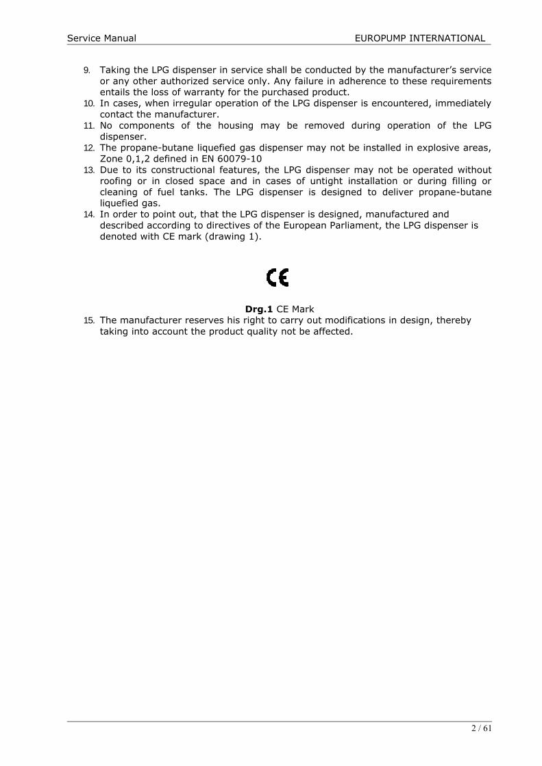
14. In order to point out, that the LPG dispenser is designed, manufactured and described according to directives of the European Parliament, the LPG dispenser is denoted with CE mark (drawing 1).
Drg.1 CE Mark15. The manufacturer reserves his right to carry out modifications in design, thereby
taking into account the product quality not be affected.
2 / 61

Service Manual EUROPUMP INTERNATIONAL
2. SAFETY OF DISPENSERS OPERATION
Owner of the filling station is liable for its operation which shall be entrusted to the trained staff only, having relevant authorization. The operator refuels vehicle tanks by LPG professionally, checks state of the fuel dispenser and the technology in the preset time intervals, checks operation of the whole unit and maintains operating records.
The prohibit of smoking and open fire handing in the area of 10 m must be fixed on a visible places next to the fuel dispenser. The notice of necessary motor switch-off, max. volume of refueling (80%) and braking the vehicle from undesirable motion has also be placed here. From the design point of view the fuel dispensers and all components which might initiate explosion are approved by the state authorized institution - the State Testing Laboratory FTZÚ Ostrava-Radvanice, which issues the necessary certificates.
For detection of possible gas leaks relevant detectors/sensors should be installed in the dispenser area.
From the hygienic point of view the device is harmless for the operator and the owner. When operating and maintaining the device, it is advisable to protect the hands by gloves.
2.1 FIRST AID
Poisoning-gaseous LPGWhen refueling, avoid LPG vapor inhalation - danger of suffocation. The injured person must be taken out of the contaminated area. Attention! Fire and explosion hazard! LPG is not poisonous, but is suffocating. In case of breathing failure carry out apply artificial breathing immediately. In case of blood circulation failure combine artificial breathing with indirect heart massage. Transfer the affected person the heath facility immediately.
Frostbites-liquid LPGIn case of steep drop of overpressure to the atmospheric pressure the liquid LPG is evaporated under the temperature of -42°C. Leak of the liquid LPG may result in frostbites, when in contact with the skin. Do not rub the frostbitten parts of the body, but cover by a sterile dressing and call the doctor.
Eyes affected by LPG shall be flushed by plenty of water. Call the doctor.
Burns-fireWhen burnt, cool the injury by cold water, do not lubricate, cover by a sterile dressing andcall the doctor. Do not remove the dress. If the clothes are burnt - do not run, extinguish by water, blanket, by rolling about ....
3 / 61

Service Manual EUROPUMP INTERNATIONAL
3. DENOTATION OF THE LPG DISPENSER
Dispenser marking
Example :
EUROSTAR E 1 -SM
X V Y Z
Eurostar Economic Type, One Nozzle, Slim Multimedia LPG Dispenser
4 / 61
MODEL T NUMBER OF NOZZLES ADDENDUMS
Modeli Tipi Tabanca Say ısı Ekler
X V Y ZEUROSTAR E Economic Type 1 -SL Slim long
T Tow er Type 2 -SS Slim Short
F Flag Type 4 -SM Slim Multimedia
-FL Flag Long
-FM Flag Multimedia
-ES Eco Short
-XL Wide Long
-XS Wide Short
-XX Extra Wide
-XM Wide Multimedia

Service Manual EUROPUMP INTERNATIONAL
4. Overal View and Descriptions of Eurostar LPG Dispensers
• Eurostar En-SL
• Eurostar En-FL
5 / 61

Service Manual EUROPUMP INTERNATIONAL
• Eurostar En-SM
• Eurostar En-FM
6 / 61
Service Manual EUROPUMP INTERNATIONAL
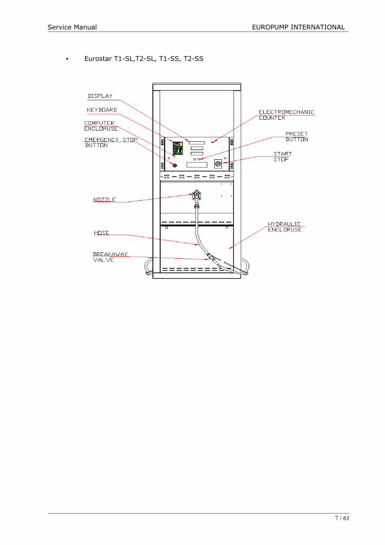
• Eurostar T1-SL,T2-SL, T1-SS, T2-SS
7 / 61
Service Manual EUROPUMP INTERNATIONAL
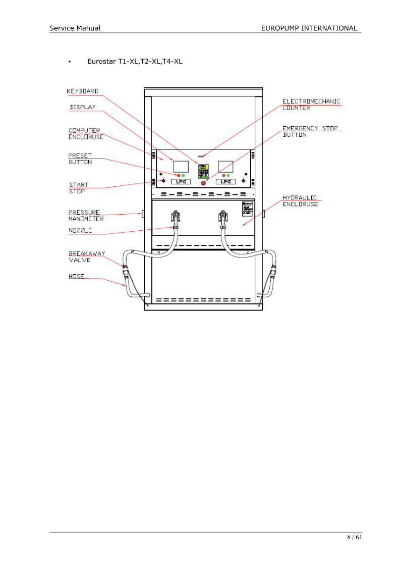
• Eurostar T1-XL,T2-XL,T4-XL
8 / 61
Service Manual EUROPUMP INTERNATIONAL
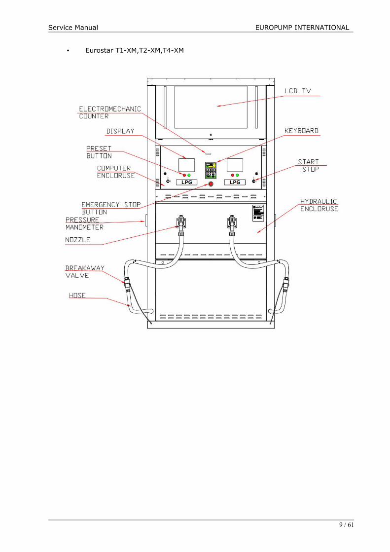
• Eurostar T1-XM,T2-XM,T4-XM
9 / 61

Service Manual EUROPUMP INTERNATIONAL
• Eurostar T1-XX,T2-XX,T4-XX
10 / 61

Service Manual EUROPUMP INTERNATIONAL
5. TRANSPORTATION
5.1 Loading and transportationMeans of transportation is determined in the contract by the customer.Handling should be made by forklift truck. Driving the forks under the transportationpalette, the LPG dispenser should be tightly secured against slippage by belts. Secure theLPG dispenser on mean of transportation against overturning and shocks, which candamage the counter and the glass elements during transportation.Follow closely instructions on package during transportation.The LPG dispenser should be transported only with covered means and in erect position.
5.2 Unloadingİmmediately upon arrival at destination, check the LPG dispenser for any damages fromtransportation, for which the carrier is liable.Unloading shall be made by driving the forklift’s forks under the palette, thereby securingtightly the LPG dispenser against slippage by belts. Then the LPG dispenser should belifted off the mean of transportation.In order to avoid any mechanical damage to the dispenser, care should be taken duringunpacking.
5.3 Storage of the LPG dispenserAlways store the LPG dispenser in dry and breezy places.During storage, always keep the liquefied and gaseous phases, placed inside the bottompart, closed.
IMPORTANT NOTICEBefore completely assembling the LPG dispenser, remove protection layer, if provided, onthe housing. Any failure to do so may cause difficulty removing the layer and givedamage to the surface.
11 / 61

Service Manual EUROPUMP INTERNATIONAL
6. INSTALLATION AND TAKING THE LPG DISPENSER INTO SERVICE
Installation and taking into service the LPG dispenser shall only be made bymanufacturer’s technical service or an authorized technical service.
Due to the construction of the LPG dispenser, it may not operate in area withoutroofing or in closed space and in cases of untight installation or during filling orcleaning of fuel tanks.
RECOMMENDATIONS
1. The pulse overvoltage can take place in any line due to lightning - up to thedistance of several kilometers – or due to industrial activities. The pulses arisen bylightning induction are quite enough for full destruction of the electronic unit. Forthis purpose the advanced countries usually apply the overvoltage protection,leading the overvoltage pulse power away into the earthing conductor, thusprotecting the unit in question. Therefore the manufacturer of fuel dispensersrecommends to protect the main (and/or the secondary) switchboard, feeding thefuel dispenser, electronic unit (computer, POS, etc.) and the data lines byovervoltage protection and lightning arresters.
2. In order to provide trouble-free operation of fuel dispensers it is necessary tosecure the stabilized dispenser feeding by the standby source - UPS. Power supplydropouts, heavy disturbances or drop of voltage in peak hours (particularly duringwinter season) are very frequent phenomena in our power supply network. Allphenomena as above can be eliminated by utilization of a correct standby source(UPS). There are two models of standby source available and suitable for the fueldispenser in our market : UPS of line interactive type UPS of on-line type
UPS of the line-interactive type is enough for stabilization in the filling stationsconnected to a very stable power supply network (without any voltage drop andwithout any disturbances).
In other cases the ON-LINE type UPS has to be applied. Disturbances, drops ofvoltage or failures can result in frequent blocking of the dispensers, problems incomputer/dispenser communication, failures of computers (data loss), etc.
3. For trouble-free operation of the fuel dispensers the signal cables have to beseparated thoroughly from the power supply cables. Parallel connection of powerand signal cables without any separation results in disturbances and undesirableparasite phenomena which may cause problems with fuel dispenser control and/oreven full damage of electronic units inside the dispensers and in the kiosk.Therefore any crossing or parallel laying (in a single bundle) of the signal andpower cables has to be prevented reliably. Separate “channels” (metal tubes,troughs) for power and signal cables represent a suitable solution. Themanufacturer is not liable for thedamages caused due to unsuitably designed cableconnection.
6.1 Cleaning of pipesTwo pipes are coming from the storage tank to the dispenser. Before installing andstarting the LPG dispenser, clean pipes to avoid debris of sand grain and metal chipsinside the pipes. Cleaning is to be done until all impurities are removed.
Driving LPG out of the fuel dispenser and piping (e.g. during disassembly) iscarried out by nitrogen or inert gas. Driving LPG out by air or oxygen isprohibited!
12 / 61
Service Manual EUROPUMP INTERNATIONAL
6.2 Execution of Foundation Foundation is to be made according to drg.10 Lay the pipes for the liquefied line and thegaseous phase return line with diameters, as in drg.10 up to the connections of the LPGdispenser, as shown in drg.10
The EUROSTAR LPG dispenser is mounted on a frame, having four M14 fixing bolt for thefour holes, diameter 16 mm in the base of the LPG dispenser, as shown in drg.10 Placethe frame on the well, level and anchor in concrete foundation. Care should be takenwhen performing these works. Having performed these works, check once again positionsof the liquefied line and the gaseous phase return line to the foundation frame and thelevel of the particular frame.
6.3 Shear valve / break point The vapour return pipe shall be provided with a means to prevent the flow of LPG fromthe piping to the atmosphere in the event of a fracture. The liquid line for delivery of LPGshall be fitted with a means to ensure the flow is automatically stopped in the event of afracture. This can be achieved by either a break point combined with excess flow valves, ashear valve or other suitable means.
The shear valve or break point shall be fixed rigidly to the dispenser and to the ground.The dispenser shall be provided with a means for mounting on a plinth or otherfoundation.
Shear valve should be used with LPG Dispensers. Installing shear valve todispenser is responsibility of station constructors.
6.4 Connection of the LPG dispenser to the suction and return lineBefore positioning the LPG dispenser on foundation (drg.5), unlock and remove frontcoverof the hydraulic system. Unscrew the palette and place the dispenser on the foundationframe. Using appropriate devices secure the dispenser on the foundation frame by meansof 4 M12 nuts.
The connection heights of liquefied and gaseous phases are ¾”, as shown in drg10. Inorder to ensure tightness of the entire hydraulic system, all hydraulic connections must besealed (Loctite 577 for gas sealings is recommended).
Personnel or firm to install the LPG dispenser in the filling station is required to fit globevalves on connecting nuts (stub pipes) of the liquefied and gaseous phases in theinstallation at the dispenser base.
The switches for operating the LPG dispenser, are placed on the LPG dispenser.
6.5 LPG Dispenser Pump Switch :The switch is operated only manually. The switch has two positions: 1 = On , O = Off In position “on”, the pump is activated and delivers pressurized liquid to the dispenser.Using the switch for purposes other than intended in the manual, is prohibited.
6.6 Emergency stop button :
The emergency stop button is placed on the side wall of the LPG dispenser at a visiblelocation “within reach”. The emergency stop button switches off the entire energy supplyto the Dispenser and LPG pump.
The emergency stop switches to open position and energy cuts off. Pullingthe button switches off and energizes.
6.7 Gas Sensor :
13 / 61

Service Manual EUROPUMP INTERNATIONAL
For detection of possible gas leaks relevant detectors/sensors should be installed in thedispenser area.
Installing shear valve to dispenser is responsibility of station constructors.
6.8 Lightining Protection
Lightning is the visible discharge of static electricity within a cloud, between clouds, orbetween tile earth and a cloud. Lightning is a major threat to LPG Gas Stations andsystems in it - not only in rare direct strikes, but also nearby strikes radiating energy to thestation. A lightning protection system does not prevent lightning from striking; it providesa means for controlling it and preventing damage by providing a low resistance path for thedischarge of lightning energy.
Sample station protection diagram based on station building
Lightining protection systems should be designed by skilled electiralengineers as it requires sensitive calculations and experience.
Lightining protection is responsibility of station constructors.
6.9 First Operation Of Dispenser
The propane-butane liquefied gas dispenser is to be serviced byauthorized technician only.
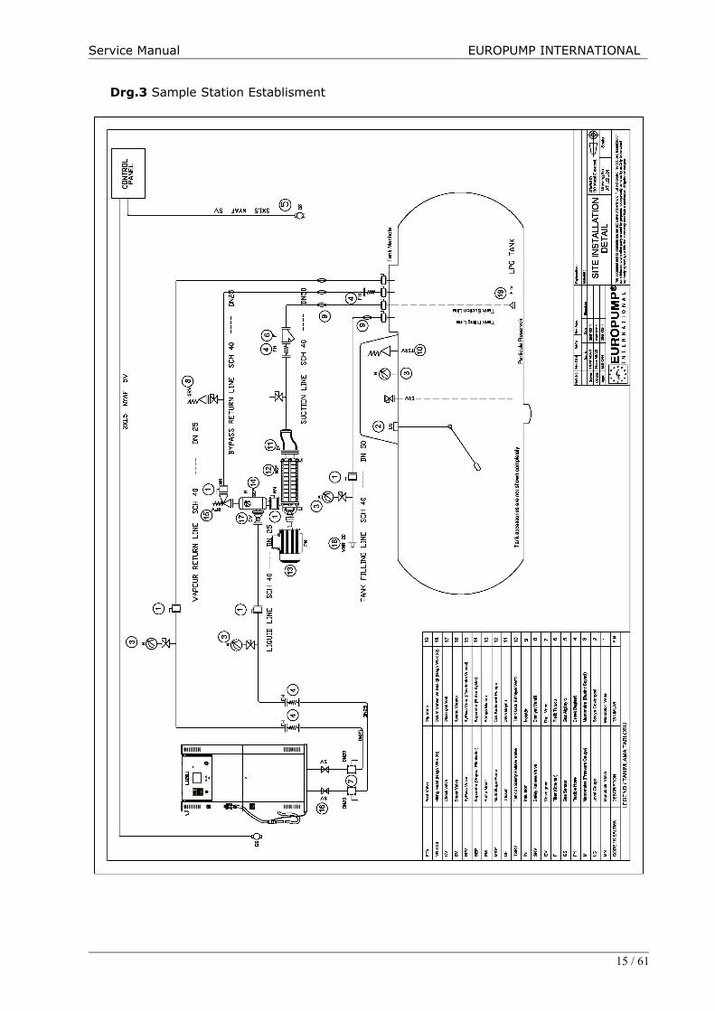
Initial state : All valves of the installation and of the tanks in the filling station are closed.
NOTICE:
If in the present service manual reference was made to open a valve, this procedureshould be made so that 10% of its operating flowrate is not exceeded by carefully andslowly shifting the lever. The valve should be maintained in this position until aconsistent pressure is established and then be opened entirely.
14 / 61
Service Manual EUROPUMP INTERNATIONAL
Drg.3 Sample Station Establisment
15 / 61

Service Manual EUROPUMP INTERNATIONAL
16 / 61

Service Manual EUROPUMP INTERNATIONAL
6.10 REFUELLING OF CARS
The propane-butane liquefied gas dispenser is to be serviced by personnel withappropriate authorizations only (according to domestic regulations).
Refuelling a car is performed by following operations:• Connect the dispenser nozzle to the appropriate place of the car to be refuelled
(connection to be tight and without leakage),• Switch on the pump by setting start-stop switch of the dispenser on position 1 (switch
on) (Check the manometer to indicate proper pressure of 1.0 to 1.3 MPa during pumpoperation);
• In case of refuelling a car brimfull (max. 80% of tank capacity), as soon as the checkvalve in the refuelled tank cuts off the gas flow to the tank, immediately switch off thepump.
NOTICE!
FILLING THE TANK TO ROUND UP SUMS OR DELIVERED VOLUMES AFTERACTIVATION OF CHECK VALVE IS STRICTLY PROHIBITED.
When refuelling is finished, switch off the pump by setting srtart-stop switch of thedispenser on position O/Switch off.Disconnect the dispenser nozzle from the vehicle and hang the nozzle at the hose-hangon the dispenser.When operation finished:• close valves of liquefied ana gaseous phases on the tank.• cut off power supply of LPG dispenser.• check that installation is tight.
6.11 Principles of Operation and Maintenance of Break-Off Safety Valves ofRepeated Use ¾” Repeated Use Break-Off ValveInstallation, use and maintenance of the repeated break-off valve is to be in conformitywith all relevant codes, rules, legal regulations. Periodical control and maintenance shallbe carried out by a qualified personel. Before installing, using and maintenancing isperformed, be sure to read and understand all instructions carefully. The final user of thegas filling station shall be familiarized with present Service Manual.
WARNING !
Contact or inhalation of liquefied propane, butane and their vapours can causeserious injuries or even death ! In order to protect human and livestock againstLPG effect, it shall be diluted by carrying away outside with an air stream. Toprevent any fire or explosion, LPG shall be stored in sufficiant distance from openfire or any source of ignition.LPG is heavier than air and therefore neither evaporating nor dissipating whensuddenly released to still air.
OperationThe ¾” breakaway valve is specially designed to ensure safety by breaking off therefuelling procedure. If fitted at the inlet of the delivery hose, it protects against leakageat both ends. At the moment of separation only some cm3 of gas will be liberated.InstallingFix release arm of valve in “upstream” position.Use M12 screw or U-screw with proper washers and nuts 3 mm diameter stainless flexiblestrand of appr. 450kgs tensile strength.
17 / 61

Service Manual EUROPUMP INTERNATIONAL
With appropriate connecting elements the valve shall have possibility to rotate so as toensure collinearity of the axis and the force axis at the moment of break off. Between stiff tubing and breakaway valve inlet a short hose shall be used. The hoselength of 30-63 cm (depending on installation) shall ensure sufficient flexibility.Fix the delivery hose with the inlet end of the break off valve.In order to state proper and reliable operation of the break off valve of repeated use thetest of breaking off shall be carried out before installation is filled with gas.
Reconnection
Before reconnection, make sure the whole inner pressure from the inlet and outlet part ofthe valve set of reuse is abolished. To reconnect simply push the male part into thefemale until the fixing balls are placed in the proper grooves of the body.Establish a pressure in the system and in order to detect leakages carry out tightnesstest on joint using high solution for leakage.
NOTICE To ensure proper operation of the break off valve, testing every 6 months isrecommended (separated and greased). As source of pressure during tests theuse of nitrogen or an other inert gas is recommended.The male part of the valve must be greased at least once a 6 months.If the valve is out of service for a longer period (e.g. seasonal operation),preserving it by spraying good quality machine oil in aerosol (e.g. WD40)or/and wrapping it against moisture is recommended.
7. MAINTENANCE
Take care of cleanness of the fuel dispenser by cleaning with a wet rag soakedwith an agent, that is appropriate to that purpose.Non-metallic surfaces of the fuel dispenser shall be cleaned with wet rag to avoidaccumulation of electric charges.Before getting started the activities, all necessary fire fighting equipment(powder extinguishers, sandbuckets, etc.) shall be held ready at the workinglocation.
7.1 Remarks relating operation
Proper and error free operation of the fuel dispenser depends on:• Proper connection and execution of the gas and electric installations,• Proper sevicing of the fuel dispenser (according to instruction),• Correctly adjusted pump (the adjustment depending on operation conditions),
And besides the above• Take care the stepped pump not to form cavitation• Do not refuel gas cylinders• Do not refuel vehicles with stretched delivery hose (possibility of breaking of the safety
valve),• Pay special attention to prevent the delivery hose not to get under a wheel of refuelled
vehicle,• Do not use open fire in the zone of explosive conditions• Observe the basic rules of industrial safety and fire fighting codes.
And besides the above
7.2 Filters
In case the of decrease in flow rate and pressure, check filters and if contaminated,replace with new ones. Replacing of filters is started from protection of the dispenser byclosing the liquefied and gaseous phases in the dispenser. In case of the EUROSTAR
18 / 61

Service Manual EUROPUMP INTERNATIONAL
dispenser, the filter between separator and meter is degassed by unscrewing the 4screws M8 to fix the cover by wrench 8 mm and the screw allowing the filter cartridge tobe removed by wrench 32 mm. Having replaced the filter cartridge and accurately fixedcover (of housing), slightly fill installation, observing the tightness of the entire system.In case of leakage, stop the work and eliminate the leakage. When remounting thecovers, it is recommended to slightly press the screws and gaskets.If at the end of all these works the flowrate values of the discharge valve do not conformto technical data, contact the manufacturer.
7.3 Greasing of rotary partsAll rotary parts, such as Hinges and locks shall be greased every 6 months.
7.4 Checking of hydraulic connections and electrical devicesCheck tightness of electrical devices and connection elements (hydraulic connections,valves, etc.), since the fuel dispenser is exposed to vibrations during operation.
7.5 Pipeline of liquefied and gaseous phasesThe tightness of nuts, connecting pipes shall be checked every three months.Moreover, after every disassembly sealing elements shall be replaced.
7.6 Warranty and Complaints
The contractual warranty is determined - the manufacturer warrants for the supplied unitis 1 year or 1 million liters of dispensed medium as a standard. The warranty does notcover the consumables (e.g. The tubular discharge lamps). When raising possible claims,the following data have to be specified:
• Serial number and name - see the rating plate• Precise description of fault and the circumstances under which the fault occurred.
The claim will not be acknowledged provided that damaged seals or non-permittedintervention into the unit were established. Defects and drawbacks following fromincorrect operation, inspection and maintenance of the fuel dispenser or its functionalassemblies are out of scope of the warranty (e.g. the problems caused by presence ofwater and impurities in the tank and the hydraulic system). Check for presence of waterand impurities and possible cleaning is necessary in the course of operation.
8. ASSEMBLY
8.1 Anchoring the dispenserAnchor the dispenser through 4 holes on the botton frame and turn lock (A).
8.2 Locking the counterClose the door of counter and turn lock (B).
8.3 Mounting the columnsPlace the screws located on columns (1, 2)
9. DISASSEMBLY
! ATTENTION !• Before opening the housing switch off power supply.• Proceed according to this Service Manual.
9.1 Opening the hydraulic housingOpen the lock located on the upper part of the housing turning it anticlockwise by 90° (for
19 / 61
Service Manual EUROPUMP INTERNATIONAL
both sides of the dispenser separately).Lift the housing and take out (appr. 15 cm) the gudgeons of the housing (located on top),then release the housing from the grips in the bottom lifting the housing and remove it.Now, access to the hydraulic housing is possible and hydraulic connections as well asperiodical controls can be carried out.
9.2 Opening of Counter EnclosureBefore any activities are made inside the counter the power master switch (motors,lighting, counter, etc.), which is situated in the room of filling station personnel, shall beswitched off.Open the counter cover turning lock.Now, access into the housing is enabled.
9.3 Opening the columnsRemove screws located on columns (1,2). Then access to cable glands, to emergency stopand key is possible.
20 / 61

Service Manual EUROPUMP INTERNATIONAL
10. SERVICE MANUAL OF ELECTRONIC
Before any activities are made inside the counter the power master switch(motors, lighting, counter etc.), which is situated in the room of filling stationpersonnel, shall be switched off.
The counter should indicate zero!
Delivery TotalField
Liter Field
Unit Price Field
VIEW OF DISPLAY
21 / 61
Service Manual EUROPUMP INTERNATIONAL
10.1 Setting of Parameters
! ATTENTION !
1. Before the housing is opened switch off the power supply
2. Proceed according to this service manual
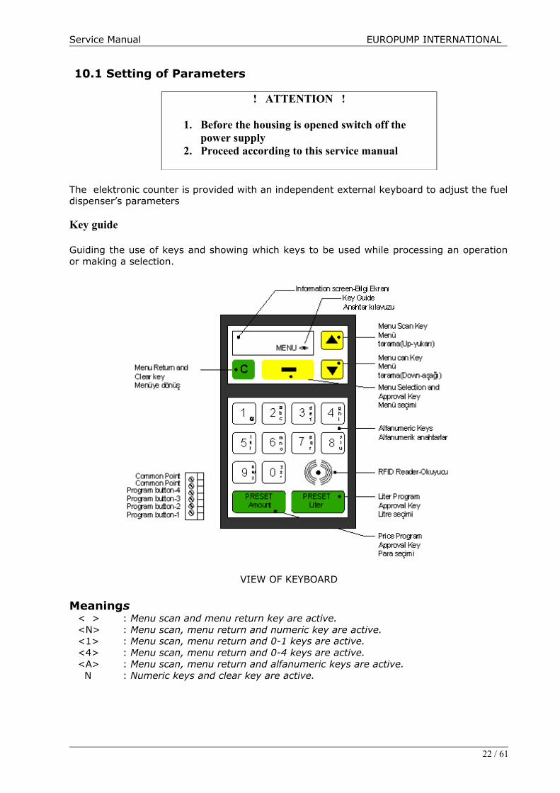
The elektronic counter is provided with an independent external keyboard to adjust the fueldispenser’s parameters
Key guide
Guiding the use of keys and showing which keys to be used while processing an operationor making a selection.
VIEW OF KEYBOARD
Meanings < > : Menu scan and menu return key are active.<N> : Menu scan, menu return and numeric key are active.<1> : Menu scan, menu return and 0-1 keys are active.<4> : Menu scan, menu return and 0-4 keys are active.<A> : Menu scan, menu return and alfanumeric keys are active. N : Numeric keys and clear key are active.
22 / 61
Service Manual EUROPUMP INTERNATIONAL
Menu selection and approval key
Used to approve selected operation by means of menu scanning keys. Facilitates operationsto be done by changing the designation of this key on the screen according to operations inthe menu in which is operated.
Menu return and clear key
Used to return to the menu and menu subfunctions and to clear digits or characters enteredwhile entering data. Each time when pressed, returns to the next higher menu or functionlevel.
Menu scan keys
Used to scan menues and subfunctions.
Programming approval keys
Used to approve entered price and liter program.
Note : If while any menu is selected no operation is made within two minutes, the systemautomatically returns to default logo screen.
Abbreviations :
DT : Screen type / makeM : Motor numberV : Valve numberP : Pulser numberD : Screen numberMK : Meksan screenS4 : S4I2C numberX : All screen types and makesB :Preset button number
23 / 61
Service Manual EUROPUMP INTERNATIONAL
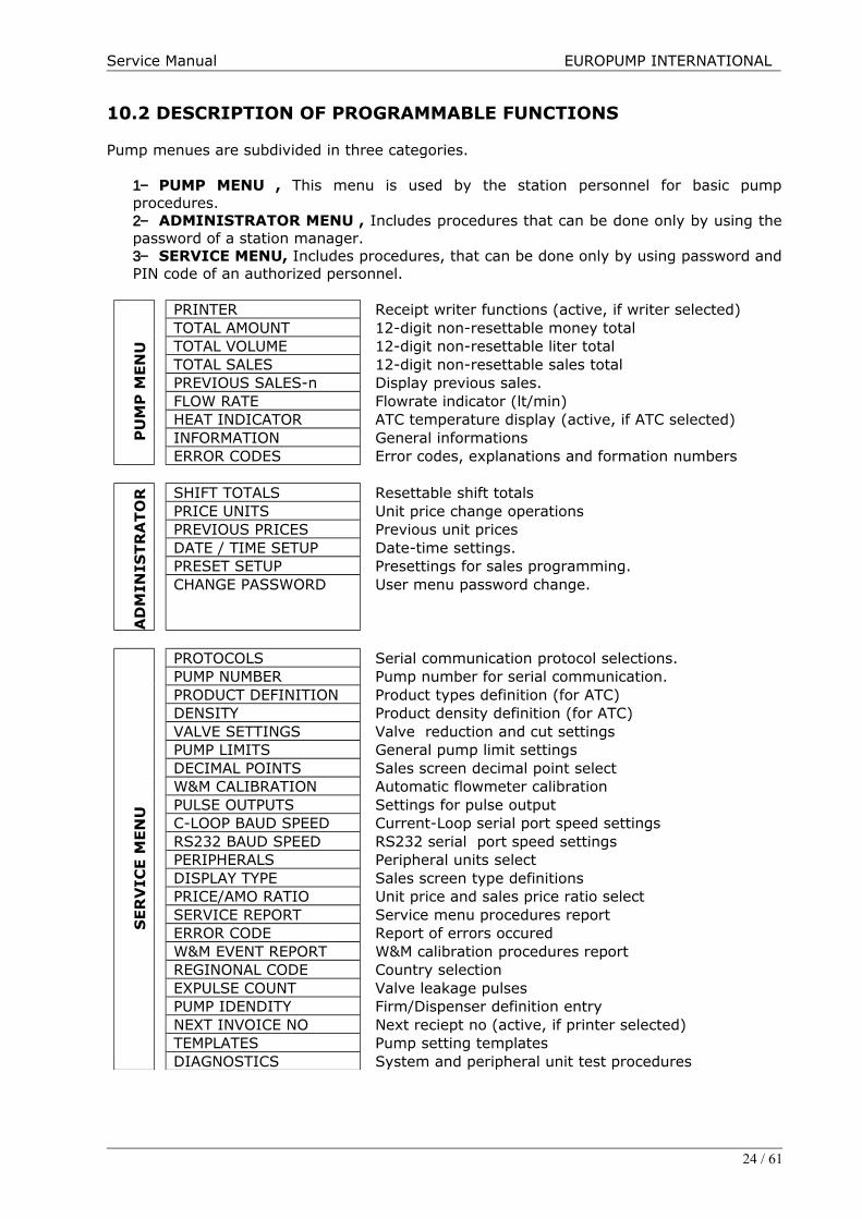
10.2 DESCRIPTION OF PROGRAMMABLE FUNCTIONS
Pump menues are subdivided in three categories.
1− PUMP MENU , This menu is used by the station personnel for basic pumpprocedures.2− ADMINISTRATOR MENU , Includes procedures that can be done only by using thepassword of a station manager.3− SERVICE MENU, Includes procedures, that can be done only by using password andPIN code of an authorized personnel.
PU
MP
MEN
U
PRINTER Receipt writer functions (active, if writer selected)TOTAL AMOUNT 12-digit non-resettable money totalTOTAL VOLUME 12-digit non-resettable liter totalTOTAL SALES 12-digit non-resettable sales totalPREVIOUS SALES-n Display previous sales.FLOW RATE Flowrate indicator (lt/min)HEAT INDICATOR ATC temperature display (active, if ATC selected)INFORMATION General informationsERROR CODES Error codes, explanations and formation numbers
AD
MIN
ISTR
ATO
R
SHIFT TOTALS Resettable shift totalsPRICE UNITS Unit price change operationsPREVIOUS PRICES Previous unit pricesDATE / TIME SETUP Date-time settings.PRESET SETUP Presettings for sales programming.CHANGE PASSWORD User menu password change.
SER
VIC
E M
EN
U
PROTOCOLS Serial communication protocol selections.PUMP NUMBER Pump number for serial communication.PRODUCT DEFINITION Product types definition (for ATC)DENSITY Product density definition (for ATC)VALVE SETTINGS Valve reduction and cut settings PUMP LIMITS General pump limit settingsDECIMAL POINTS Sales screen decimal point selectW&M CALIBRATION Automatic flowmeter calibrationPULSE OUTPUTS Settings for pulse outputC-LOOP BAUD SPEED Current-Loop serial port speed settingsRS232 BAUD SPEED RS232 serial port speed settingsPERIPHERALS Peripheral units selectDISPLAY TYPE Sales screen type definitionsPRICE/AMO RATIO Unit price and sales price ratio selectSERVICE REPORT Service menu procedures reportERROR CODE Report of errors occuredW&M EVENT REPORT W&M calibration procedures reportREGINONAL CODE Country selectionEXPULSE COUNT Valve leakage pulsesPUMP IDENDITY Firm/Dispenser definition entryNEXT INVOICE NO Next reciept no (active, if printer selected)TEMPLATES Pump setting templatesDIAGNOSTICS System and peripheral unit test procedures
24 / 61
Service Manual EUROPUMP INTERNATIONAL
10.2.1. PUMP MENU
EMERGENCY STOP
Used for emergency stop while filling, if appropriate.For operation logo screen should be visible. ( If you are inside te menu, return to logoscreen by menu return key)Select nozzle no. of nozzle you want to stop, using the menu scan keys. You may exitoperation by menu return key.On display the no. of nozzle to be stopped visible.Pressing the approval key, you can stop nozzle you selected.
PASSWORD CHANGE
Password entry procedure to enter administrator and service menu. A 4-digit password isrequired to enter the administrator menu. This password may also be changed throughadministrator menu and factory set “0000”. For th service menu a 6-digit password and a4-digit PIN-code are required, whereby PIN-code differs for every authorized personnel.Once inside the service menu all menus are activated, whereas inside the administratormenu, pump service menus are activated.
Administrator menu entry :
For operation logo screen should be visible.Enter the 4-digit password pressing the numeric keys. You may clear entered digitsbackwards in case of need.Approve password pressing approval the key.You may exit menu by menu return key.
Service menu entry :
For operation logo screen should be visible.Enter the 6-digit by pressing numeric keys. Using clear key you may clear entered digitsbackwards, if need be.Approve entered password by pressing approval key.If entered 6-digit service password is correct, PIN-code will be prompted. Entering PIN-code, when approved service menu will be activated,.You may exit the menu using menu return key.
SALES PROGRAMMING
Used for programming pump sales amounts (money and liter) prior to transaction. Presetprogramming procedures are done using keypad and preset buttons. Preset programmingoperations are carried out by using keypad or preset buttons. Inside the administratormenu preset changes for preset buttons and keypad can be carried out.In order to cancel entered programme, carry out following procedur by entering “0”.For the operation the logo screen should appear.Enter required amount to be programmed using numeric keys. By means of clear key youmay clear backwards entered digits.If in your presettings zeros are defined, these will be appended to the entered amount.For Liter press “Amount”, for money press “Volume” key.If several filling points provided, nozzle no. will be prompted.Entering the nozzle no., programmed amount will appear on the screen.
25 / 61

Service Manual EUROPUMP INTERNATIONAL
Programming with Preset Button :
For every sales point, depending on pump construction settings 1-4 units of preset buttonsare available. Every time the button is pressed, the nozzle being in place, the previouslydefined button-1 amount will be doubled up and be visible on the sales screen. In order tocancel the programme keep button pressed during 2-3 seconds, preset will be reset to zeroand the last sales screen will appear.
Notes :
1− For multiple product single sales point pumps, the given preset amount will beapplicable to the product, of which the nozzle has been taken up first.
2− The entered preset amount is unvalid, if it is outside the sales screen limits.3− The preset operation will be cancelled after expiry of time, defined in the presettings (if
no sale was made within that time)4− For preset operations, valve settings in the service menu must be adjusted.5− The preset buttons can effect changes depending on the number of filling points. If only
one filling point provided, 4 buttons for the same filling point programmable, ifsimultaneously 4 filling points provided, for each filling point one button will be valid.
PRINTER MENU :
If a reciept printer is connected to system and active. Pump salesman can print out shiftreport or last sale reciept from this menu.
PRICE, LITER AND SALES TOTALS :
Undeletable price, liter and sales totals are accumulated totals of the sales.If inside the menu, using scan keys; if in the logo screen, initially using approval key andthen by means of menu scan keys, you may select out from “PRICE TOTALS”,”LITERTOTALS” or “SALES TOTALS” whichever you wish to view.Pressing the approval key, you may view totals you selected.If several filling points provided, by means of menu scan keys you may view the totals ofother nozzles. The digit “(1)” on the top left corner of the screen indicates the nozzle no.By means of menu return key you may exit the menu.
PREVIOUS SALES
Indicates the money total of the last transaction.
If inside the menu using scan keys, if inside the logo screen using initially the approval keyafterwards menu scan keys, select “PREVIOUS SALES” menu.Pressing the approval key, you may view previous transaction amounts. If several filling points provided, you may view sales of other nozzles using the menu scankeys. By means of menu return key you may exit the menu.
FLOWRATE
Indicates the amount of last sale.
If inside the menu using scan keys, if inside the logo screen using initially the approval keyafterwards menu scan keys, select “FLOWRATE INDICATOR” menu.Pressing the approval key, you may view flowrate of the pump. If several filling points provided, you may view flowrates of other nozzles using menu scankeys. The digit “1” in the top left corner of the screen indicates the nozzle no.By means of menu return key you may exit the menu.
26 / 61
Service Manual EUROPUMP INTERNATIONAL
TEMPERATURE INDICATOR
If ATC feature is active, sensor temperatures and CTE (thermal expansion coefficient)values are indicated (if this feature is not selected from peripherals menu, not visible insidethe menu).
If inside the menu using scan keys, if inside the logo screen using initially the approval keythen afterwards menu scan keys, select “TEMPERATURE INDICATOR” menu.Pressing the approval key, you may view sensor temperatures.By means of menu return key you may exit the menu.
INFORMATION
Indicates meanings and no. of occurence of error messages appearing on sales screen unitprice display.
If inside the menu using scan keys, if inside the logo screen using initially the approval keyafterwards menu scan keys, select “INFORMATION” menu.Enter subfunctions pressing approval key.Select required information using menu kesy.Indicates pump configuration setting and selected sales screen type.Indicates Program version and date of installation.Shows current date and hour.Indicates mains voltage.Indicates program CRC value.Indicates pump operation condition.Indicates operation intensity of the microprocessor.Indicates passwords and PIN-codes related definitions.By means of menu return key you may exit the menu.
ERROR CODES
Indicates meanings and no. of occurrence of error messages appearing on sales screen unitprice display.
If inside the menu, using scan keys, if inside the logo screen using initially the approval keyafterwards menu scan keys, select “ERROR MESSAGES” menu.Pressing approval key, view error messages.Using the menu scan keys, select error message you require.By means of menu return key you may exit the menu.
27 / 61
Service Manual EUROPUMP INTERNATIONAL
10.2.2. ADMINISTRATOR MENU
SHIFT TOTALSDeletable price totals of nozzles.
If inside the menu, using scan keys, if inside logo screen, first using administratorpassword, afterwards using approval key and menu scan key, select “SHIFT TOTALS" menu.Pressing the approval key you may view shift totals.If several filling points provided, you may view shift totals of other nozzles by means ofmenu scan keys. The digit “[1]:” on the top left corner of the screen indicates the nozzleno.Using menu return key you may exit menu.
PRICE UNITS
If inside menu using scan keys, if inside logo screen, first using approval key and thenmenu scan keys select “UNIT PRICES” menu.Pressing the approval key you may view and change unit prices you wish to change.If several filling points provided, you may change unit prices of other nozzles using menuscan keys. The digit “[1]:” on the top left corner of the screen indicates the nozzle no.Using numeric keys you may change prices. Approve prices changes pressing the approvalkey.Using menu return key you may exit menu or you may backwards delete starting from thelast digit entered.
Note : Unit prices you changed, are visible on the screen when nozzle is activated.
PREVIOUS PRICES
From this menu you can trace previous prices with changed date and hour.
If inside the menu using scan keys, or if inside the logo screen first using approval key andthen using menu scan keys select “PREVIOUS PRICES” menu.Pressing the approval key you may view previous prices.If several filling points are provided, by means of menu scan keys you may view prices ofother nozzles. The digit “[19]” on the top left corner of the screen indicates the nozzle no.On the left bottom corner of the screen date and time of change can be seen.Using menu return key you may exit the menu.
TIME-DATE SETUP
If inside the menu using scan keys, if inside the logo screen, first using approval key andthen menu scan key select “DATE/TIME” menu.Pressing the approval key you may view and change date and time settings.Using numeric keys you may enter date and hour settings. Pressing the approval keytoggles to the next selection. Using the menu scan keys you may select setting needed. By means of menu scan key you may exit the menu or delete backwards starting from thelast digit entered.
PRESET SETUP
Definitions for sales programming (preset) are made.
If inside the menu using scan keys, if inside the logo screen first entering the administratorpassword, afterwards using approval key and menu scan key select “PRESETTINGS”.Pressing the approval key you may enter subfunctions and by means of menu scan keysview and change the entered values.
28 / 61
Service Manual EUROPUMP INTERNATIONAL
Preset button value no.1,Preset button value no.2,Preset button value no.3,Preset button value no.4,If no transaction has been made within the minute after programming, made by means ofkeyboard, the programme will be cancelled.Using the numeric keys you may enter settings.You may exit the menu by means of menu return key or delete backwards starting from thelast entered digit.
PASSWORD CHANGE
If inside the menu using scan keys, if inside the logo screen first entering the administratorpassword, then using approval key and menu scan keys slect “PASSWORD CHANGE” menu.Pressing the approval key you may change administrator password.Using the numeric keys you may enter the 4-digit admnistrator password and activate bymeans of approval key.Using the menu return key you may exit the menu or delete backwards starting from lastentered digit.
29 / 61
Service Manual EUROPUMP INTERNATIONAL
10.2.3. SERVICE MENU
PROTOCOLS
For serial communication protocol selection is made.
Order of key entry:If inside the menu using scan keys, or if inside the logo screen first using approval key andthe using menu scan keys select “PROTOCOLS” menu.Pressing the approval key you may view selected protocol.By means of menu scan keys you may select other protocols and pressing the approval keyactivate selected protocol.Pressing approval key approve selection.Using menu return key you may exit the menu.
Protocols:Standalone : Operates independent from pump serial communication.S4-dart : Extended DART protocol.PSN-DART : Default DART protocol.Modbus : Communication witth mass meters
Note: Detailed information about dart protocols is set forth in “SERIAL COMMUNICATION andDART PROTOCOL” documentation.
PUMP NUMBER
For serial communication pump number selection is made.
If inside the menu using scan keys, or if inside the logo screen first using approval key andthe using menu scan keys select “PUMP NUMBER” menu.Pressing the approval key you may view and change selected protocol.Using the two-digit numeric keys (0-99) you may enter pump number and activate byapproval key.By means of menu scan key you may exit menu or delete backwards starting fromthe last entered digit.
PRODUCT TYPE
For every nozzle a product density definition is made, which is needed for ATC function.
If inside the menu using scan keys, if inside the logo screen first entering the servicepassword and PIN-code, then using approval key and menu return key select “PRODUCTDEFINITION” menu.Pressing the approval key you may view and change previously defined product types.If several filling points are provided, you may change product types of other nozzles. Thedigit “[1]:” on the top left corner of the screen indicates the nozzle number.Using numeric keys 1-9 you may change product type. Approve selection by pressingapproval key.By means of menu return key you may exit the menu.
PRODUCT DENSITY
For every nozzle a product density definition is made, which is needed for ATC function.
30 / 61

Service Manual EUROPUMP INTERNATIONAL
If inside the menu using scan keys, if inside the logo screen first entering the servicepassword and PIN-code, then using approval key and menu return key select “DENSITY”menu.Pressing the approval key you may view and change previously defined density values.If several filling points are provided, you may change density values of other nozzles. Thedigit “[1]:” on the top left corner of the screen indicates the nozzle number.Using numeric keys you may change density values. Approve selection by pressing approvalkey.By means of menu return key you may exit the menu or delete backwards last entereddigits.
VALVE SETUP
For preset function valve definitions are made.
If inside the menu using scan keys, if inside the logo screen first entering the servicepassword and PIN-code, then using approval key and menu return key, select “DENSITY”menu.Pressing the approval key you may enter subfunctions, using the menu scan keys you mayview and change entered values.For previously programmed sales (peset) value, reduction value prior to preset termination(in mm).(if entered zero, automatically adjusts cut value)Using numeric keys you may change ve settings. Pressing approval key approve selectedchange.lYou may exit menu by means of menu return key or delete backwards starting from the lastentered digit.
PUMP LIMITS
General pump definitions.
If inside the menu using scan keys, if inside logo screen first enter service password andPIN-code, then using approval key and menu scan keys select “PUMP LIMITS” menu.Pressing the approval key you may enter subfunctions, using menu scan keys you may viewand change entered values.Test screen duration when nozzle lifted. (sec)Stand-by time when nozzle put back. (sec)If within entered value (sec) after lifting nozzle no transaction is made, the engine stops.Last digit of Litre screen (ml x 10). After entered value screen activated.At flowrates higher than entered values in liters, shut-off of nozzle is retarded.If for LPG pumps transaction is made under the entered flowrate value in liters, after theLPG Off-Time the engine stops.For LPG Offset value lapse of time in seconds.Limit value of price field. If entered zero, limitless. (after 99999999, starting from zero)Liter field limit value. If entered zero, limitless. (after 9999.99 starting from zero)Serial communication DART protocol lapse time Using numeric keys you may change pump limits. Approve selected change by pressingapproval key.By means of menu return key you may exit the manu or delete backwards starting from thelast entered digit.
DECIMAL POINTS
Decimal point locations of price, liter and unit price fields of sales screen are defined.
31 / 61

Service Manual EUROPUMP INTERNATIONAL
If inside the menu using scan keys, if inside logo menu first entering service password andPIN-code, then using approval key and menu scan keys, select “DECIMAL POINTS” menu. Pressing the approval key you may enter subfunctions, using menu scan keys you may viewand change entered values.Unit price decimal point definition.Liter decimal point definition.Price decimal point definition.Using numeric keys you may change decimal point definitions.Approve changes pressing the approval key.By means of menu return key you may exit the menu or delete backwards starting from thelast entered digit.
W&M CALIBRATION
Automatic flowmeter calibration carried out.
If inside the menu using scan keys, if inside logo menu first entering service password andPIN-code, then using approval key and menu scan keys, select “W&M CALIBRATION” menu.Pressing the approval key you may enter subfunctions.If several filling points provided, select using menu scan keys flowmeter to be calibrated.The digit “[1]:” on the top left corner of the screen indicates the nozzle no.After selecting flowmeter follow below steps for calibrating ;
1. Keep a completely empty 10 liter measuring vessel ready.2. Lift the nozzle and fill up the vessel up to scaling line.3. Press approval (Set) key when made sure filled amount is equal to amount of
measuring vessel.
By means of menu return key you may exit menu.
PULSE OUTPUTS
If inside the menu using scan keys, if inside the logo screen first enter service passwordand PIN-code, then using approval key and menu scan key select “PULSE RATIOS” menu.By means of menu scan key you may exit the menu.
C-LOOP BAUD RATE
For Current-Loop serial communication unit, baud speed is defined.
If inside the menu using scan keys, if inside the logo screen first enter service passwordand PIN-code, then using approval key and menu scan key select “C-LOOP BAUD SPEED”menu.Pressing approval key you may enter subfunctions, using menu scan keys you may viewand change selected values.Having selected BAUD speed value to be changed press approval key.By means of menu scan key you may exit the menu.
RS 232 BAUD RATE
For RS232 serial communication unit baud speed is defined.If inside the menu using scan keys, if inside the logo screen first enter service passwordand PIN-code, then using approval key and menu scan key select “RS232 BAUD SPEED”menu.Pressing approval key you may enter subfunctions, using menu scan keys you may viewand change selected values.Having selected BAUD speed value to be changed press approval key.
32 / 61
Service Manual EUROPUMP INTERNATIONAL
By means of menu scan key you may exit the menu.
PERIPHERALS
Selection of active / passive peripheral units
If inside the menu using scan keys, if inside the logo screen first enter service passwordand PIN-code, then using approval key and menu scan key select “PERIPHERAL UNITS”menu.
Pressing approval key you may enter subfunctions, using menu scan keys you may viewand change selected values.Pressing key 1 you may activate, pressing 0 deactivate selected unit.Approve performed operation by pressing approval key.By means of menu scan key you may exit the menu.
DISPLAY TYPE
Sales screen type selection.
If inside the menu using scan keys, if inside the logo screen first enter service passwordand PIN-code, then using approval key and menu scan key select “SALES SCREEN TYPE”menu.Pressing approval key you may enter subfunctions, using menu scan keys you may viewand change selected screen type.Approve performed operation by pressing approval key.By means of menu scan key you may exit the menu.
PRICE/AMO RATIO
For calculations unit price/total ratios are defined.
If inside the menu using scan keys, if inside the logo screen first enter service passwordand PIN-code, then using approval key and menu scan key select “UNIT/PRICE RATIO”menu.Pressing approval key you may enter subfunctions, using menu scan keys you may viewand change selected ratio.Approve performed operation by pressing approval key.By means of menu scan key you may exit the menu.
SERVICE LOG
Up to 250 operations of entering service menu by date, hour and PIN-code may be tracedbackwards. If inside the menu using scan keys, if inside the logo screen first enter service passwordand PIN-code, then using approval key and menu scan key select “SERVICE REPORT”menu.Pressing approval key enter to reports.By means of menu scan keys you may trace records onwards and backwards. In the topline of the screen you may see date and hour, in the bottom line PIN-code.
ERROR LOG
Up to 250 operations of error codes occured by date, hour and PIN-code may be tracedbackwards.
33 / 61

Service Manual EUROPUMP INTERNATIONAL
If inside the menu using scan keys, if inside the logo screen first enter service passwordand PIN-code, then using approval key and menu scan key select “ERROR CODE” menu.Pressing approval key enter to reports.By means of menu scan keys you may trace records onwards. In the top line of the screenyou may see date and hour, in the bottom line nozzle no.By means of menu scan key you may exit the menu.
W&M EVENT LOG
W&M calibration operations may be traced 250 changes backwards by date, hour andcalibration value.
If inside the menu using scan keys, if inside the logo screen first enter service passwordand PIN-code, then using approval key and menu scan key select “W&M REPORT” menu.Onay tuşunu kullanar Pressing approval key enter to reports.By means of menu scan keys you may trace records onwards and backwards. In the topline of the screen you may see date and hour, in the bottom line nozzle no.By means of menu scan key you may exit the menu.
REGINOAL CODE
If inside the menu using scan keys, if inside the logo screen first enter service passwordand PIN-code, then using approval key and menu scan key select “COUNTRY CODE” menu.
Pressing approval key you may enter subfunctions, using menu scan keys you may viewand change selected country code values.Approve performed operation by pressing approval key.By means of menu scan key you may exit the menu.
EXPULSE COUNT
Shows leakage quantities while nozzle is closed.
PUMP IDENTITY
Pump identity definition number is used for printer operations, in order to specify uniquepump id.Pressing approval key you may view and change previously defined value.Using numeric keys you may change firm definition values. Pressing approval key you mayapprove performed changes. By means of menu return key you may exit menu or deletebackwards starting from the last entered digit.
NEXT INVOICE NO
Definition is used for printer operatiıons to specify next reciept no.
TEMPLATES
Template definitions depending on pump type.
If inside the menu using scan keys, if inside the logo screen first enter service passwordand PIN-code, then using approval key and menu scan key select “TEMPLATES” menu.Pressing approval key you may view subfunctions, using menu scan keys you may view andchange selected template.Approve performed operation by pressing approval key.By means of menu scan key you may exit the menu.
34 / 61
Service Manual EUROPUMP INTERNATIONAL
DIAGNOSTICS
If inside the menu using scan keys, if inside the logo screen first enter service passwordand PIN-code, then using approval key and menu scan key select “SYSTEM CONTROL”menu.Pressing approval key you may enter subfunctions, using menu scan keys you may selectunit to be tested. Approve performed operation by pressing approval key.By means of menu scan key you may exit the menu.
35 / 61

Service Manual EUROPUMP INTERNATIONAL
10.3. GENERAL COMPUTER CONNECTION
S4 PRO-B
PRO-C
36 / 61
Service Manual EUROPUMP INTERNATIONAL
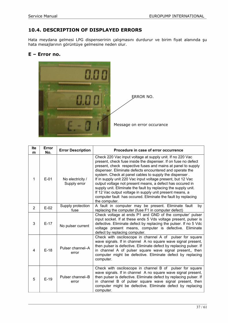
10.4. DESCRIPTION OF DISPLAYED ERRORS
Hata meydana gelmesi LPG dispenserinin çalışmasını durdurur ve birim fiyat alanında şuhata mesajlarının görüntüye gelmesine neden olur.
E – Error no.
ERROR NO.
Message on error occurance
Item
ErrorNo.
Error Description Procedure in case of error occurrence
1 E-01 No electricity /Supply error
Check 220 Vac input voltage at supply unit. If no 220 Vac present, check fuse inside the dispenser. If on fuse no defect present, check respective fuses and mains at panel to supply dispenser. Eliminate defects encountered and operate the system. Check at panel cables to supply the dispenser .If in supply unit 220 Vac input voltage present, but 12 Vac output voltage not present means, a defect has occured in supply unit. Eliminate the fault by replacing the supply unit.If 12 Vac output voltage in supply unit present means, a computer fault has occured. Eliminate the fault by replacing the computer.
2 E-02Supply protection
fuseA fault in computer may be present. Eliminate fault byreplacing the computer (fuse F1 in computer defect)
3 E-17No pulser current
Check voltage at ends P1 and GND of the computer’ pulserinput socket. If at these ends 5 Vds voltage present, pulser isdefective. Eliminate defect by replacing the pulser. If no 5 Vdcvoltage present means, computer is defective. Eliminatedefect by replacing computer.
4 E-18Pulser channel–A
error
Check with osciloscope in channel A of pulser for squarewave signals. If in channel A no square wave signal present,then pulser is defective. Eliminate defect by replacing pulser. Ifin channel A of pulser square wave signal present,, thencomputer might be defective. Eliminate defect by replacingcomputer.
5 E-19Pulser channel–B
error
Check with osciloscope in channel B of pulser for squarewave signals. If in channel A no square wave signal present,then pulser is defective. Eliminate defect by replacing pulser. Ifin channel B of pulser square wave signal present, thencomputer might be defective. Eliminate defect by replacingcomputer.
37 / 61

Service Manual EUROPUMP INTERNATIONAL
6 E-20Pulser channelsadverse
Error eliminated by connecting pulser channel ends correctly.
7 E-24Communicationprotocolincompatible
Check protocol values from administrator menu. Error eliminated by using compatible communication protocol.
8 E-25 Serial Line LossCheck SW1 switch if Modbus mode onn and cpu is connected to suitable massmeter.
9 E-26Electromechanicaltotalisor error
Check electromechanical total connection. If there is no fault inconnection, change electromechanical total.
10 E-29Nozzle open(electricity cut off)
Place nozzle in boot. If error persists, check switch and if defective replace. If no defect on switch observed, check cables enabling communication between computer and switch.If cables not found to be defective, replace computer.
11 E-31Unit price notentered
Entering the unit price, error can be eliminated.
12 E-36Liter field beyondlimit
If in system liter total limitation is set for each sale, thedispenser can not sell more than the set amount for everysale. If required, limitation can be cancelled by entering max.amo. value 0 (zero) from service menu.
13 E-37Money fieldbeyond limit
If in system sales amount limitation is set for each sale, thedispenser can not sell more than the set liters for every sale. Ifrequired, limitation can be cancelled by entering max. vol.value 0 (zero) from service menu.
14 E-39Solenoid valveleakage
Error occures, when in preset delivery mode, product deliveryexceeds preset value. Check solenoid valves.
15 E-42Servicemenu/W&M active
Temporary error code. Occures when lifting nozzle while inservice menu or W&M switch is active. Insert nozzle back intoboot, leave service menu, then lift nozzle.
16 E-43 WATCHDOG timeexpiry
Error in case of product delivery under value entered intocomputer. Eliminated by inserting nozzle back into nozzleboot.
38 / 61
Service Manual EUROPUMP INTERNATIONAL
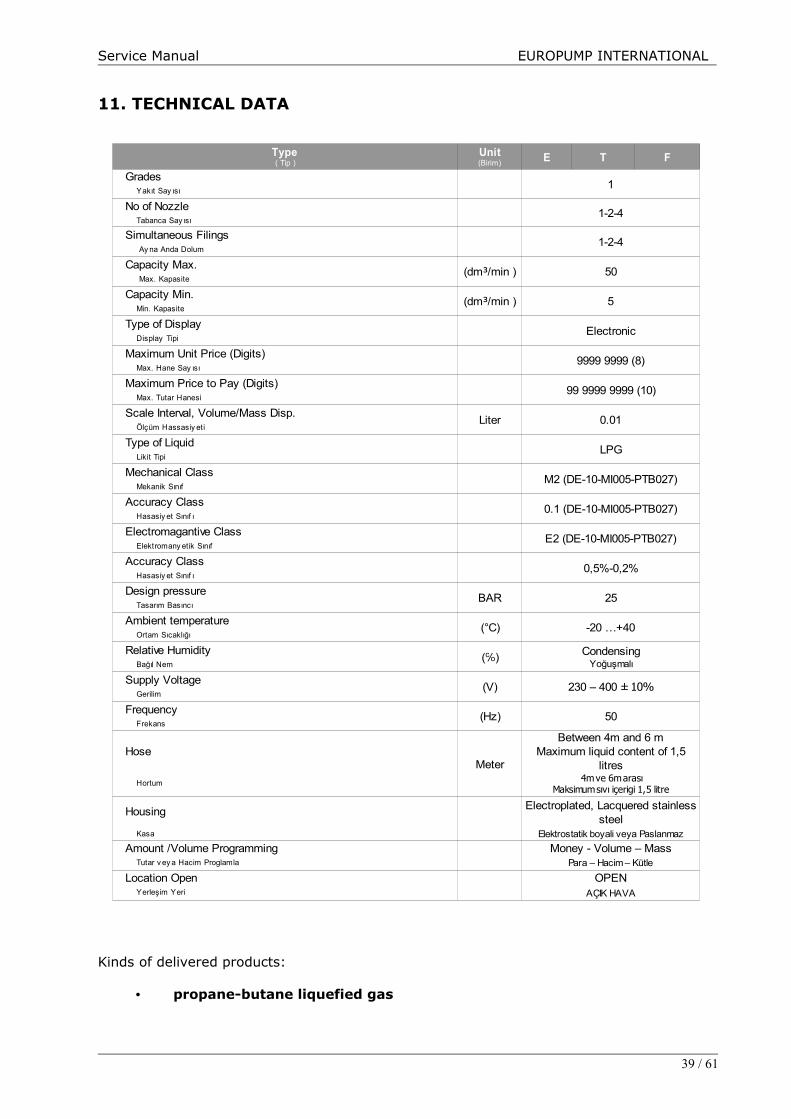
11. TECHNICAL DATA
Kinds of delivered products:
• propane-butane liquefied gas
39 / 61
E T F
Grades1
Yakıt Say ısı
No of Nozzle1-2-4
Tabanca Say ısı
Simultaneous Filings1-2-4
Ay na Anda Dolum
Capacity Max.50
Max. Kapasite
Capacity Min.5
Min. Kapasite
Type of DisplayElectronic
Display Tipi
Maximum Unit Price (Digits)9999 9999 (8)
Max. Hane Say ısı
Maximum Price to Pay (Digits)99 9999 9999 (10)
Max. Tutar Hanesi
Scale Interval, Volume/Mass Disp.Liter 0.01
Ölçüm Hassasiy eti
Type of LiquidLPG
Likit Tipi
Mechanical ClassM2 (DE-10-MI005-PTB027)
Mekanik Sınıf
Accuracy Class0.1 (DE-10-MI005-PTB027)
Hasasiy et Sınıf ı
Electromagantive ClassE2 (DE-10-MI005-PTB027)
Elektromany etik Sınıf
Accuracy Class0,5%-0,2%
Hasasiy et Sınıf ı
Design pressureBAR 25
Tasarım Basıncı
Ambient temperature(°C) -20 …+40
Ortam Sıcaklığı
Relative Humidity(℅)
Bağıl Nem
Supply Voltage(V)
Gerilim
Frequency (Hz) 50
Frekans
HoseMeter
Hortum
Housing
Kasa Elektrostatik boyali veya Paslanmaz
Amount /Volume Programming Money - Volume – MassTutar v ey a Hacim Proglamla Para – Hacim – Kütle
Location Open OPENYerleşim Yeri AÇIK HAVA
Type( Tip )
Unit(Birim)
(dm³/min )
(dm³/min )
CondensingYoğuşmalı
230 – 400 ± 10%
Between 4m and 6 mMaximum liquid content of 1,5
litres 4m ve 6m arası
Maksimum sıvı içerigi 1,5 litre
Electroplated, Lacquered stainless steel

Service Manual EUROPUMP INTERNATIONAL
12. BREAKDOWN REPAIRS
Any repair shall be made by trained persons provided with proper competence.Before any activities are made inside the LPG dispenser the power master switch (motors, lighting, counter, etc.) , which is situated in the room of filling station personnel, shall be switched off.
Always cut off power supply by switching power master switch off.
40 / 61
Service Manual EUROPUMP INTERNATIONAL
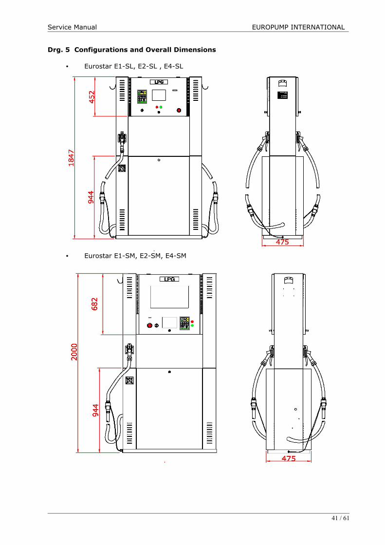
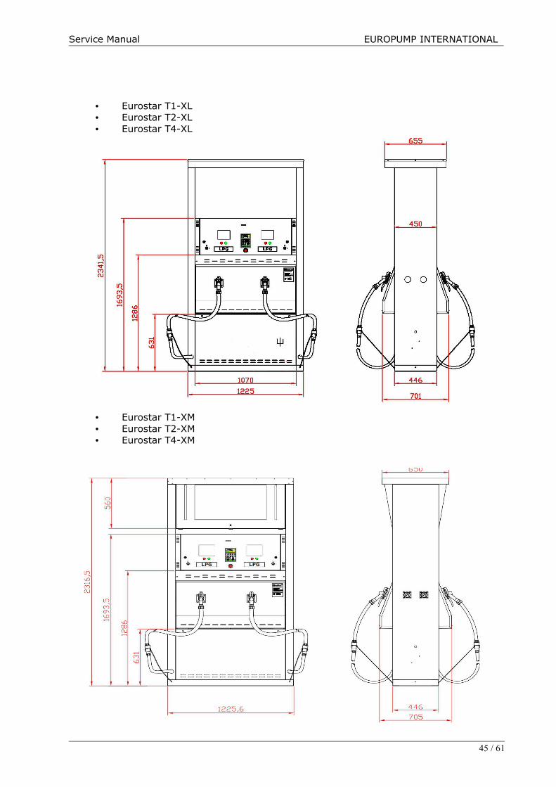
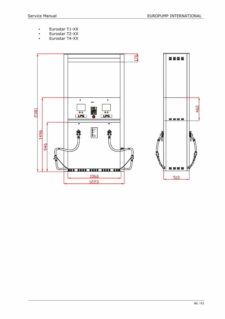
Drg. 5 Configurations and Overall Dimensions
• Eurostar E1-SL, E2-SL , E4-SL
• Eurostar E1-SM, E2-SM, E4-SM
41 / 61
Service Manual EUROPUMP INTERNATIONAL
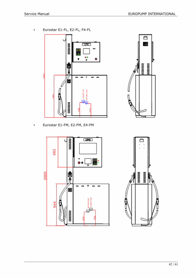
• Eurostar E1-FL, E2-FL, F4-FL
• Eurostar E1-FM, E2-FM, E4-FM
42 / 61

Service Manual EUROPUMP INTERNATIONAL
• Eurostar T1-SL• Eurostar T2-SL
43 / 61

Service Manual EUROPUMP INTERNATIONAL
• Eurostar T1-SS • Eurostar T2-SS
• Eurostar T1-ES• Eurostar T2-ES
44 / 61
Service Manual EUROPUMP INTERNATIONAL
• Eurostar T1-XL• Eurostar T2-XL• Eurostar T4-XL
• Eurostar T1-XM• Eurostar T2-XM• Eurostar T4-XM
45 / 61
Service Manual EUROPUMP INTERNATIONAL
• Eurostar T1-XX• Eurostar T2-XX• Eurostar T4-XX
46 / 61
Service Manual EUROPUMP INTERNATIONAL
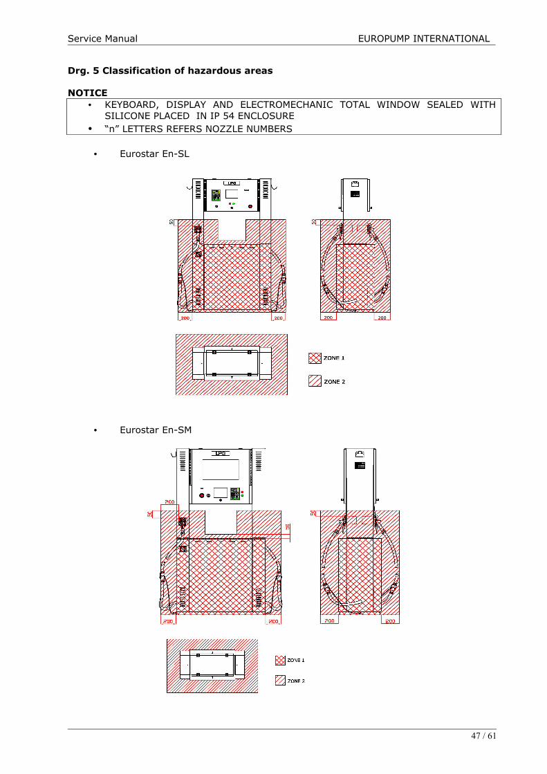
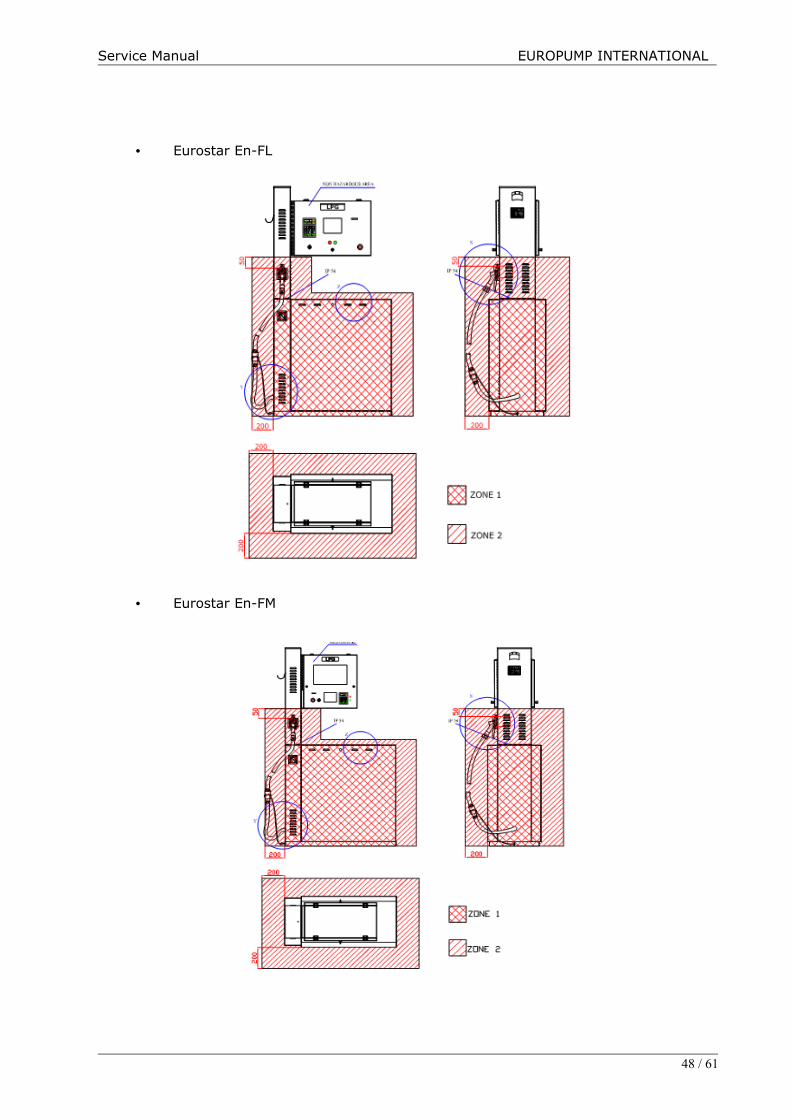
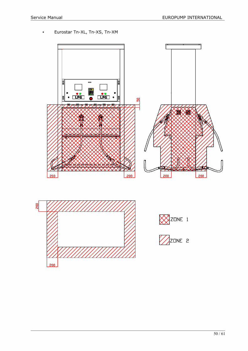
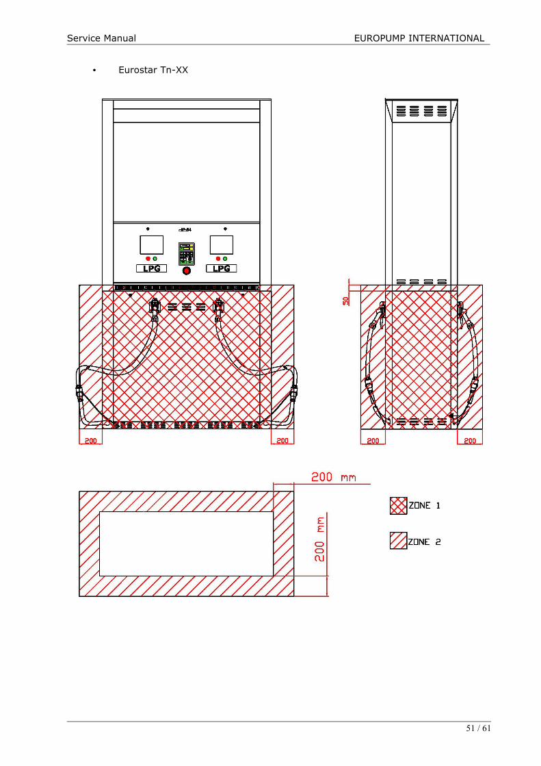
Drg. 5 Classification of hazardous areas
NOTICE • KEYBOARD, DISPLAY AND ELECTROMECHANIC TOTAL WINDOW SEALED WITH
SILICONE PLACED IN IP 54 ENCLOSURE• “n” LETTERS REFERS NOZZLE NUMBERS
• Eurostar En-SL
• Eurostar En-SM
47 / 61
Service Manual EUROPUMP INTERNATIONAL
• Eurostar En-FL
• Eurostar En-FM
48 / 61

Service Manual EUROPUMP INTERNATIONAL
• Eurostar Tn-SL, Tn-SS, Tn-ES
49 / 61
Service Manual EUROPUMP INTERNATIONAL
• Eurostar Tn-XL, Tn-XS, Tn-XM
50 / 61
Service Manual EUROPUMP INTERNATIONAL
• Eurostar Tn-XX
51 / 61
Service Manual EUROPUMP INTERNATIONAL
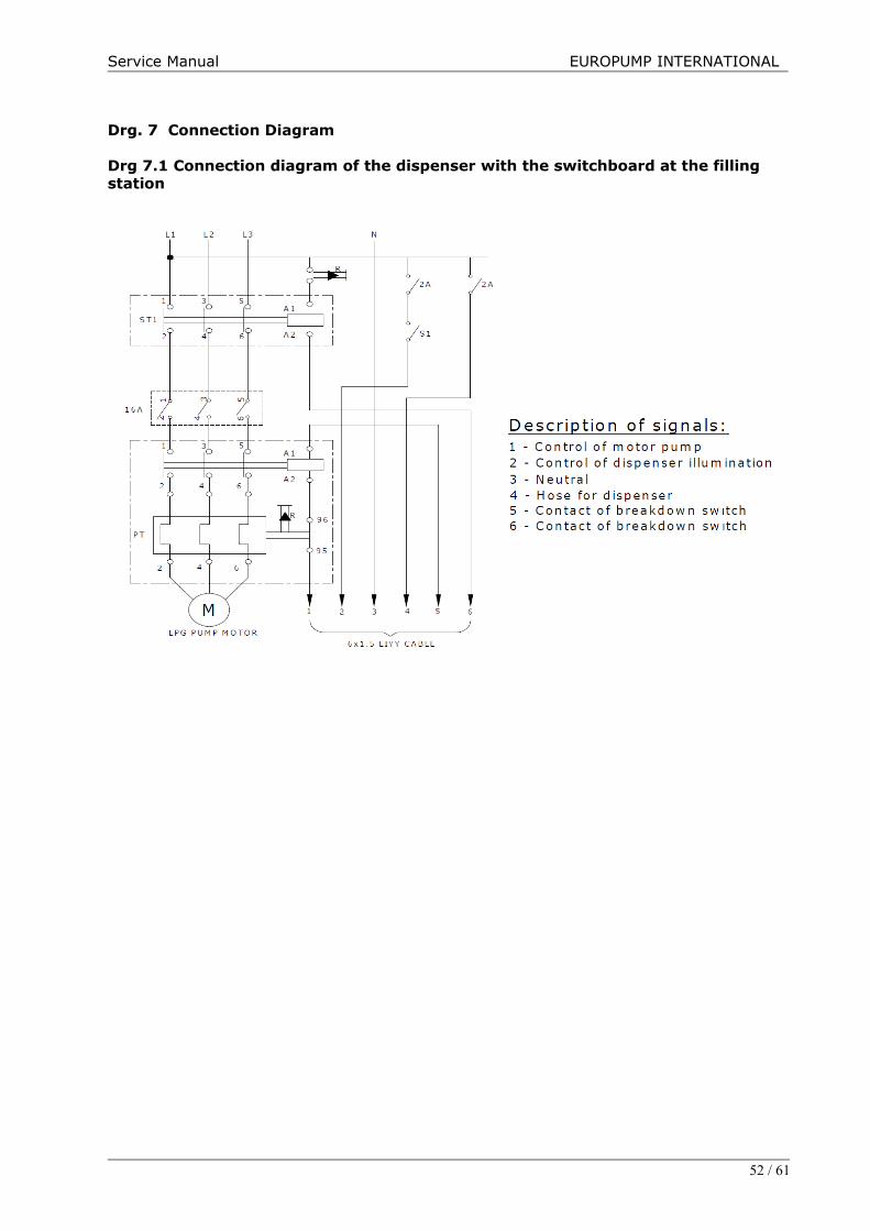
Drg. 7 Connection Diagram
Drg 7.1 Connection diagram of the dispenser with the switchboard at the filling station
52 / 61

Service Manual EUROPUMP INTERNATIONAL
Drg. 7.2 Junction box connection diagram of the Eurostar Dispensers
Single Nozzle
Multiple Nozzle
53 / 61
Service Manual EUROPUMP INTERNATIONAL
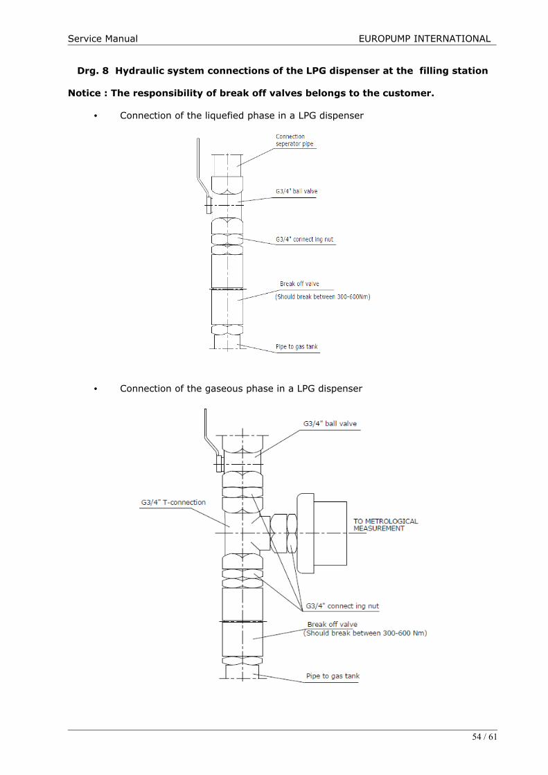
Drg. 8 Hydraulic system connections of the LPG dispenser at the filling station
Notice : The responsibility of break off valves belongs to the customer.
• Connection of the liquefied phase in a LPG dispenser
• Connection of the gaseous phase in a LPG dispenser
54 / 61

Service Manual EUROPUMP INTERNATIONAL
Drg. 9 Hydraulic system diagram for single nozzle dispensers
Drg. 9.1 Hydraulic system diagram for single nozzle dispensers
55 / 61
Service Manual EUROPUMP INTERNATIONAL
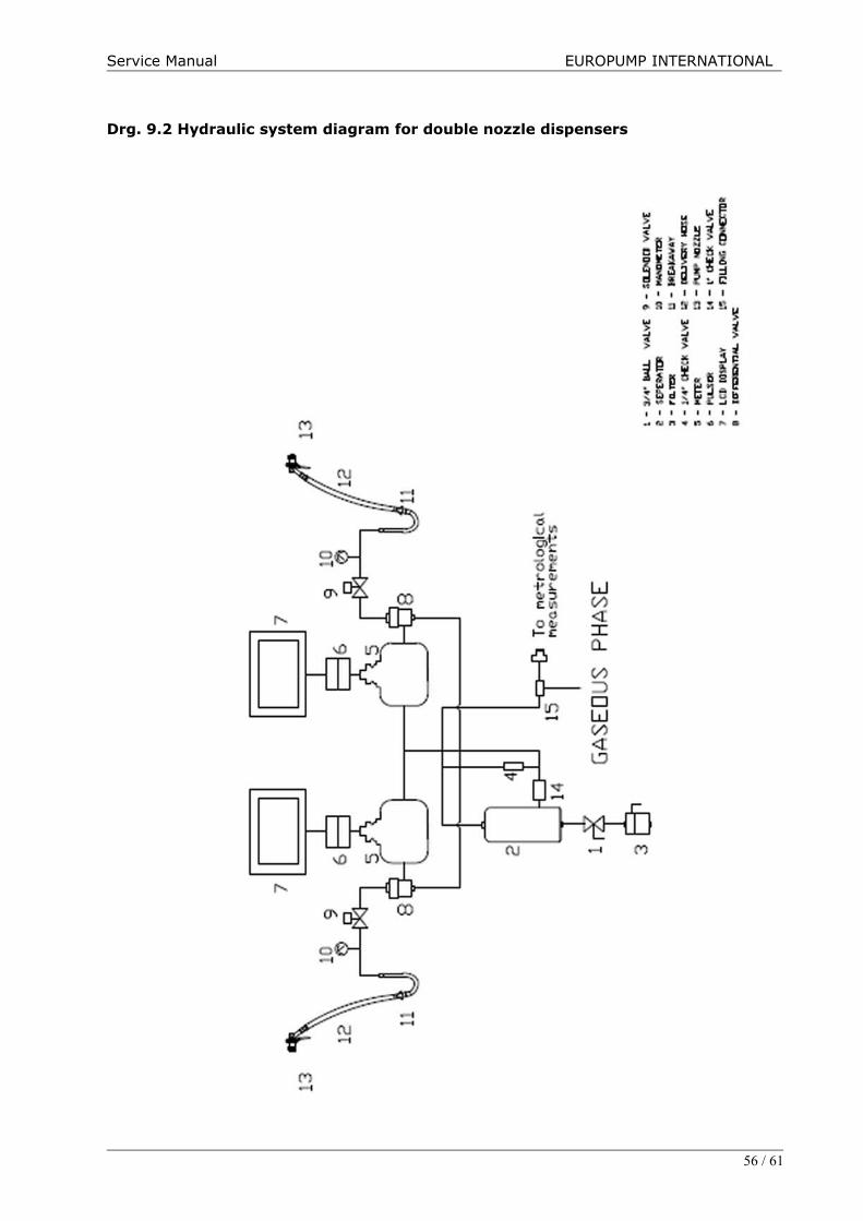
Drg. 9.2 Hydraulic system diagram for double nozzle dispensers
56 / 61
Service Manual EUROPUMP INTERNATIONAL
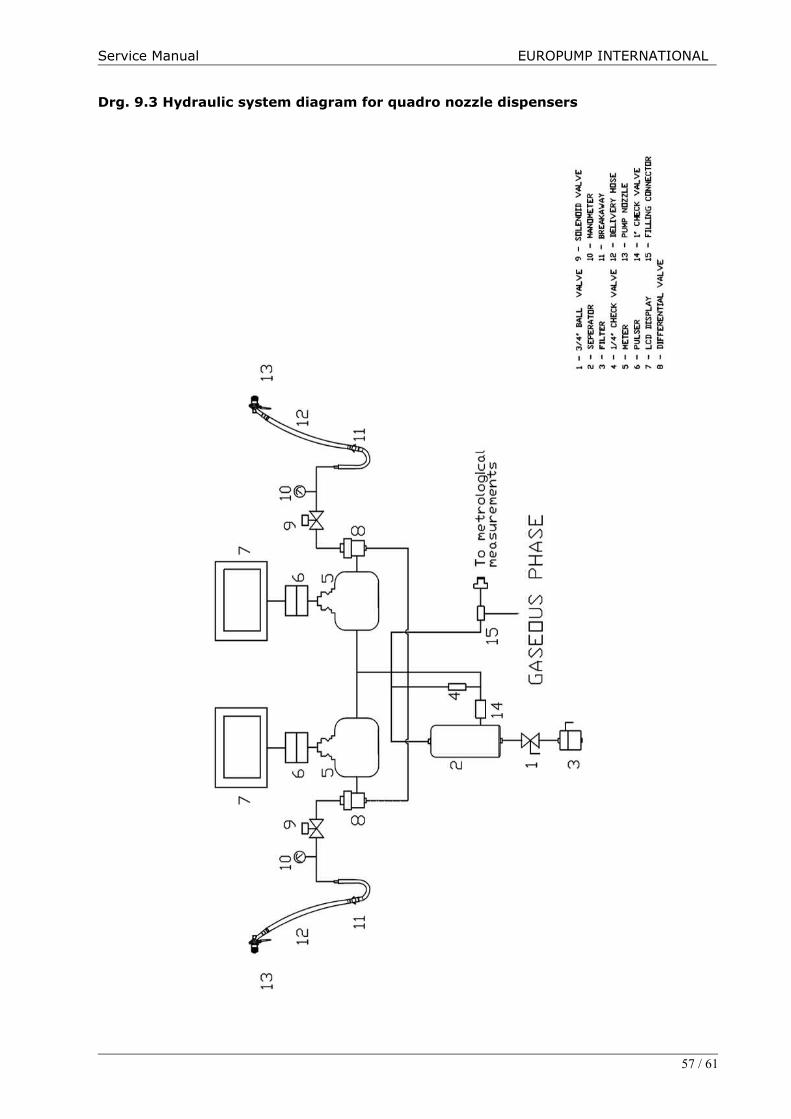
Drg. 9.3 Hydraulic system diagram for quadro nozzle dispensers
57 / 61
Service Manual EUROPUMP INTERNATIONAL
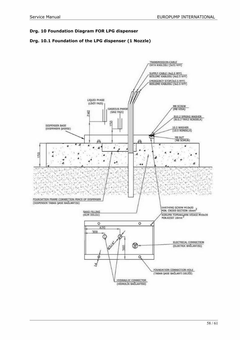
Drg. 10 Foundation Diagram FOR LPG dispenser
Drg. 10.1 Foundation of the LPG dispenser (1 Nozzle)
58 / 61

Service Manual EUROPUMP INTERNATIONAL
Drg. 10.2 Foundation of the LPG dispenser (2 Nozzle)
59 / 61
Service Manual EUROPUMP INTERNATIONAL
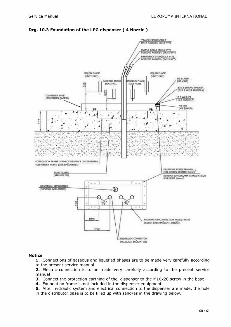
Drg. 10.3 Foundation of the LPG dispenser ( 4 Nozzle )
Notice1. Connections of gaseous and liquefied phases are to be made very carefully accordingto the present service manual2. Electric connection is to be made very carefully according to the present servicemanual3. Connect the protection earthing of the dispenser to the M10x20 screw in the base.4. Foundation frame is not included in the dispenser equipment5. After hydraulic system and electrical connection to the dispenser are made, the holein the distributor base is to be filled up with sand/as in the drawing below.
60 / 61
Service Manual EUROPUMP INTERNATIONAL
13. CONTACT US :
Please do not hessitate to contact us for your all kind of technical and sales support fromour website www.europump.com or following worldwide offices :
USA :Europump USA41 Saxon Ave , Bayshore NY 11706 USAE-mail : [email protected] Telephone: +1 201 266 02 42 Fax :+1 201 399 33 03
ITALY :Europump Italia SRLVIA CASIGNOLO, 24 20092 CINISELLO BALSAMO (MI) ITALIAE-mail: [email protected] Telephone: +39 02 66014608 (708) Fax: +39 02 6600523
TURKEY :Europump Aky.Techizatlari San. ve Tic. A.S.Nisantepe Mh.Edip Sk. B17 Cekmekoy-Istanbul TURKEYE-mail: [email protected] Telephone: +90 216 365 35 70 Fax: +90 216 365 35 72
POLAND :EUROPUMP POLSKA Spółka z o. o.86-300 Grudziądz ul. Rapackiego 37 PolandE-mail: [email protected] Telephone: +48 56 64 11 666 Fax: +48 56 64 11 665
61 / 61