service manual - Термотрейдfile.thermotrade.ru/techno/servicedanilov/vrv/vrviii/service...
TRANSCRIPT
SiEN34-705
Service
Manual
Design, Installation & Testing InstructionR-410A Heat Pump 50Hz/60Hz
Cooling Only 50HzRXYQ5PY1(E)RXYQ8PY1(E)RXYQ10PY1(E)RXYQ12PY1(E)RXYQ14PY1(E)RXYQ16PY1(E)RXYQ18PY1(E)RXYQ20PY1(E)RXYQ22PY1(E)RXYQ24PY1(E)RXYQ26PY1(E)RXYQ28PY1(E)RXYQ30PY1(E)RXYQ32PY1(E)RXYQ34PY1(E)RXYQ36PY1(E)RXYQ38PY1(E)RXYQ40PY1(E)RXYQ42PY1(E)RXYQ44PY1(E)RXYQ46PY1(E)RXYQ48PY1(E)RXYQ50PY1(E)RXYQ52PY1(E)RXYQ54PY1(E)
RXYQ5PYL(E)RXYQ8PYL(E)RXYQ10PYL(E)RXYQ12PYL(E)RXYQ14PYL(E)RXYQ16PYL(E)RXYQ18PYL(E)RXYQ20PYL(E)RXYQ22PYL(E)RXYQ24PYL(E)RXYQ26PYL(E)RXYQ28PYL(E)RXYQ30PYL(E)RXYQ32PYL(E)RXYQ34PYL(E)RXYQ36PYL(E)RXYQ38PYL(E)RXYQ40PYL(E)RXYQ42PYL(E)RXYQ44PYL(E)RXYQ46PYL(E)RXYQ48PYL(E)RXYQ50PYL(E)RXYQ52PYL(E)RXYQ54PYL(E)
RXQ5PY1RXQ8PY1RXQ10PY1RXQ12PY1RXQ14PY1RXQ16PY1RXQ18PY1RXQ20PY1RXQ22PY1RXQ24PY1RXQ26PY1RXQ28PY1RXQ30PY1RXQ32PY1RXQ34PY1RXQ36PY1RXQ38PY1RXQ40PY1RXQ42PY1RXQ44PY1RXQ46PY1RXQ48PY1RXQ50PY1RXQ52PY1RXQ54PY1

SiEN34-705
Table of Contents i
R-410A Series
Part 1 General Information ...........................................................11. Product Outline .......................................................................................2
1.1 Model Names of Indoor/Outdoor Units.....................................................21.2 External Appearance................................................................................31.3 Combination of Outdoor Units ..................................................................61.4 Model Selection......................................................................................10
2. Points to Bear in Mind at the System Design........................................122.1 Points Relating to the Performance of the Air Conditioning Units ..........122.2 The Installation is of Vital Importance ....................................................142.3 Striking a Balance between System Installation and General Construction
Work (Comprehensive Flow Chart)152.4 Points to Bear in Mind when Preparing the Contract Drawings .............16
3. Installation .............................................................................................193.1 Step by Step Installation Procedure .......................................................193.2 Work Involved in Individual Operations and Points to be Borne in Mind20
4. Test Operation ......................................................................................824.1 Procedure and Outline ...........................................................................824.2 Operation when Power is Turned On .....................................................864.3 Outdoor Unit PC Board Layout...............................................................874.4 Field Setting ...........................................................................................88
5. Caution for Refrigerant Leaks .............................................................1245.1 Caution for Refrigerant Leaks ..............................................................124
6. Hand Over to Customer ......................................................................1276.1 Operational Steps.................................................................................127
7. Appendix .............................................................................................1287.1 Operating Noise of Indoor Units ...........................................................1287.2 Piping Installation Point ........................................................................1307.3 Example of Connection (R-410A type).................................................1327.4 Refrigerant Branch Kit Selection ..........................................................1367.5 Pipe Size Selection ..............................................................................1397.6 How to Calculate the Additional Refrigerant to be Charged.................1417.7 Size of Main Gas and Liquid Pipes and Allowable Length ...................1427.8 Record of Field Setting and Additional Refrigerant Charge .................1447.9 Outdoor Unit Multi Connection Piping Kit .............................................1457.10 REFNET Joint and Header...................................................................1607.11 VRV Inspection Sheet ..........................................................................1657.12 Piping System Diagrams ......................................................................1707.13 Wiring Diagrams (Heat Pump 50Hz/60Hz, Cooling Only 50Hz)...........1827.14 Bad Examples and Good Examples in Installation...............................1957.15 Malfunction of Transmission Examples................................................210
SiEN34-705
ii Table of Contents
Part 2 Installation Manual ........................................................2131. Heat Pump / Cooling Only 50Hz (RX(Y)Q5~54P)...............................214
1.1 First of All .............................................................................................2151.2 Introduction...........................................................................................2181.3 Selection of Location ............................................................................2221.4 Inspecting and Handling the Unit .........................................................2241.5 Placing the Unit ....................................................................................2251.6 Refrigerant Piping.................................................................................2261.7 Field Wiring ..........................................................................................2381.8 Air Tight Test and Vacuum Drying .......................................................2461.9 Pipe Insulation......................................................................................2481.10 Checking of Device and Installation Conditions ...................................2491.11 Additional Refrigerant Charge and Check Operation ...........................2501.12 Onsite Settings .....................................................................................2571.13 Test Run...............................................................................................2581.14 Caution for Refrigerant Leaks ..............................................................259
2. Heat Pump 60Hz (RXYQ5~54P).........................................................2612.1 First of All .............................................................................................2622.2 Introduction...........................................................................................2652.3 Selection of Location ............................................................................2692.4 Inspecting and Handling the Unit .........................................................2712.5 Placing the Unit ....................................................................................2722.6 Refrigerant Piping.................................................................................2732.7 Field Wiring ..........................................................................................2862.8 Air Tight Test and Vacuum Drying .......................................................2942.9 Pipe Insulation......................................................................................2962.10 Checking of Device and Installation Conditions ...................................2972.11 Additional Refrigerant Charge and Check Operation ...........................2982.12 Onsite Settings .....................................................................................3052.13 Test Run...............................................................................................3062.14 Caution for Refrigerant Leaks ..............................................................307
Part 3 Operation Manual ...........................................................3091. Heat Pump / Cooling Only 50Hz (RX(Y)Q5~54P) ............................. 310
1.1 Safety Cautions ......................................................................... 3111.2 Specifications ............................................................................ 3121.3 What to do before Operation ..................................................... 3121.4 Remote Control and COOL/HEAT Selector: Name and Function of
Each Switch and Display(Refer to figure 2 and 3)............................................................. 313
1.5 Operation Range ....................................................................... 3131.6 Operation Procedure ................................................................. 3131.7 Optimum Operation ................................................................... 3171.8 Seasonal Maintenance .............................................................. 3171.9 Following Symptoms are not Air Conditioner Troubles.............. 3171.10 Trouble Shooting ....................................................................... 319
2. Heat Pump 60Hz (RXYQ5~54P)........................................................ 3212.1 Safety Cautions ......................................................................... 3222.2 Specifications ............................................................................ 3232.3 What to do before Operation ..................................................... 3232.4 Remote Control and COOL/HEAT Selector: Name and Function of

SiEN34-705
Table of Contents iii
each Switch and Display (Refer to figure 2 and 3) .................... 3232.5 Operation Range ....................................................................... 3242.6 Operation Procedure ................................................................. 3242.7 Optimum Operation ................................................................... 3282.8 Seasonal Maintenance .............................................................. 3282.9 Following Symptoms are not Air Conditioner Troubles.............. 3282.10 Trouble Shooting ....................................................................... 330
Part 4 Precautions for New Refrigerant (R-410A) ....................3331. Precautions for New Refrigerant (R-410A) .........................................334
1.1 Outline ..................................................................................................3341.2 Refrigerant Cylinders............................................................................3361.3 Service Tools........................................................................................337
Index ............................................................................................. i
Drawings & Flow Charts ............................................................... iii

Preface
This system is a modular zone controllable air conditioning system of great sophistication which is capable of assembly in a variety of different configurations. It would, however, be no exaggeration to say that the full potential of the systems functions can only be achieved in combination with the skills of those involved in the design of the equipment itself and those responsible for the installation work.
As the move towards intelligent buildings has gathered momentum, so we have also been seeing ever more a growing demand for a wider range of independently controllable building related functions.
Against this background there have also quite naturally been calls for the development of more distributed types of air conditioning systems while at the same time taking full account of the need to use energy economically by demand matching in view of the huge annual increases in the demand for electric power seen in recent years.
We have therefore prepared this installation manual to enable installation work to be handled confidently on the basis of a clear understanding of the special features of this system. We have paid particular attention to points of difference in installation procedure between this system and the more traditional package and room air conditioning system.
The manual is designed specifically to cater for those supervising installation work and concentrates on those products which are currently on the market. Essential points which need to be taken into consideration when designing an appropriate configuration for the system and in each of the separate installation processes have also been included.
We have also added a section covering problems which have arisen in connection with installation work undertaken to date in an attempt to prevent the recurrence of the same problems.
Please be sure to read this manual thoroughly before starting installation work in order to ensure that all such work is carried out with maximum efficiency and to maximum effect.
The following technical documents are also available from Daikin. Please use these documents together with this manual to conduct efficient servicing.
May, 2007
After Sales Service Division
Title Pub.:No. Published InService Manual VRVIII R-410A Heat Pump 50Hz P Series Si34-601 Jun., 2006Service Manual VRVIII R-410A Heat Pump 60Hz P Series Si34-605 Feb., 2007Service Manual VRVIII R-410A Cooling Only 50Hz P Series Si34-704 Mar., 2007

SiEN34-705
General Infomation 1
Part 1General Information
1. Product Outline .......................................................................................21.1 Model Names of Indoor/Outdoor Units.....................................................21.2 External Appearance................................................................................31.3 Combination of Outdoor Units ..................................................................61.4 Model Selection......................................................................................10
2. Points to Bear in Mind at the System Design........................................122.1 Points Relating to the Performance of the Air Conditioning Units ..........122.2 The Installation is of Vital Importance ....................................................142.3 Striking a Balance between System Installation and
General Construction Work (Comprehensive Flow Chart) .....................152.4 Points to Bear in Mind when Preparing the Contract Drawings .............16
3. Installation .............................................................................................193.1 Step by Step Installation Procedure .......................................................193.2 Work Involved in Individual Operations and
Points to be Borne in Mind .....................................................................204. Test Operation ......................................................................................82
4.1 Procedure and Outline ...........................................................................824.2 Operation when Power is Turned On .....................................................864.3 Outdoor Unit PC Board Layout...............................................................874.4 Field Setting ...........................................................................................88
5. Caution for Refrigerant Leaks .............................................................1245.1 Caution for Refrigerant Leaks ..............................................................124
6. Hand Over to Customer ......................................................................1276.1 Operational Steps.................................................................................127
7. Appendix .............................................................................................1287.1 Operating Noise of Indoor Units ...........................................................1287.2 Piping Installation Point ........................................................................1307.3 Example of Connection (R-410A type).................................................1327.4 Refrigerant Branch Kit Selection ..........................................................1367.5 Pipe Size Selection ..............................................................................1397.6 How to Calculate the Additional Refrigerant to be Charged.................1417.7 Size of Main Gas and Liquid Pipes and Allowable Length ...................1427.8 Record of Field Setting and Additional Refrigerant Charge .................1447.9 Outdoor Unit Multi Connection Piping Kit .............................................1457.10 REFNET Joint and Header...................................................................1607.11 VRV Inspection Sheet ..........................................................................1657.12 Piping System Diagrams ......................................................................1707.13 Wiring Diagrams (Heat Pump 50Hz/60Hz, Cooling Only 50Hz)...........1827.14 Bad Examples and Good Examples in Installation...............................1957.15 Malfunction of Transmission Examples................................................210
Product Outline SiEN34-705
2 General Information
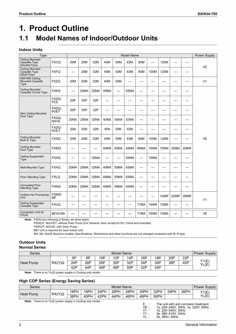
1. Product Outline1.1 Model Names of Indoor/Outdoor UnitsIndoor Units
Note: FXDQ has following 2 Series, as show below.FXDQ-P, N(A)VET: without Drain Pump (For General, Asia: except for EU, China and Australia)FXDQ-P, N(A)VE: with Drain PumpBEV unit is required for each indoor unit.MA, NA: RoHS Directive models; Specifications, Dimensions and other functions are not changed compared with M, N type.
Outdoor UnitsNormal Series
Note: There is no YL(E) power supply in Cooling only model.
High COP Series (Energy Saving Series)
Note: There is no YL(E) power supply in Cooling only model.
Type Model Name Power SupplyCeiling Mounted Cassette Type (Double Flow)
FXCQ 20M 25M 32M 40M 50M 63M 80M � 125M � �VE
Ceiling Mounted Cassette Type(Multi Flow)
FXFQ � 25M 32M 40M 50M 63M 80M 100M 125M � �
600×600 Ceiling Mounted Cassette Type
FXZQ 20M 25M 32M 40M 50M � � � � � � V1
Ceiling Mounted Cassette Corner Type FXKQ � 25MA 32MA 40MA � 63MA � � � � �
VE
Slim Ceiling Mounted Duct Type
FXDQ-PVE 20P 25P 32P � � � � � � � �
FXDQ-PVET 20P 25P 32P � � � � � � � �
FXDQ-NAVE 20NA 25NA 32NA 40NA 50NA 63NA � � � � �
FXDQ-NVET 20N 25N 32N 40N 50N 63N � � � � �
Ceiling Mounted Built-In Type FXSQ 20M 25M 32M 40M 50M 63M 80M 100M 125M � �
Ceiling Mounted Duct Type FXMQ � � � 40MA 50MA 63MA 80MA 100MA 125MA 200MA 250MA
Ceiling Suspended Type FXHQ � � 32MA � � 63MA � 100MA � � �
Wall Mounted Type FXAQ 20MA 25MA 32MA 40MA 50MA 63MA � � � � �
Floor Standing Type FXLQ 20MA 25MA 32MA 40MA 50MA 63MA � � � � �
Concealed Floor Standing Type FXNQ 20MA 25MA 32MA 40MA 50MA 63MA � � � � �
Outdoor Air Processing Unit
FXMQ-MF � � � � � � � � 125MF 200MF 250MF
V1Ceiling Suspended Cassette Type FXUQ � � � � � � 71MA 100MA 125MA � �
Connection Unit for FXUQ BEVQ-MA � � � � � � 71MA 100MA 125MA � � VE
Series Model Name Power Supply
Heat Pump RX(Y)Q5P 8P 10P 12P 14P 16P 18P 20P 22P
Y1(E)YL(E)24P 26P 28P 30P 32P 34P 36P 38P 40P
42P 44P 46P 48P 50P 52P 54P
Series Model Name Power Supply
Heat Pump RX(Y)Q16PH 18PH 24PH 26PH 28PH 30PH 32PH 34PH 36PH Y1(E)
YL(E)38PH 40PH 42PH 44PH 46PH 48PH 50PH
E : The unit with anti corrosion treatmentVE : 1φ, 220~240V, 50Hz, 1φ, 220V, 60HzV1 : 1φ, 220~240V, 50HzY1 : 3φ, 380~415V, 50HzYL : 3φ, 380V, 60Hz
SiEN34-705 Product Outline
General Information 3
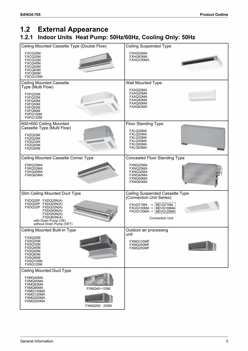
1.2 External Appearance1.2.1 Indoor Units Heat Pump: 50Hz/60Hz, Cooling Only: 50HzCeiling Mounted Cassette Type (Double Flow)
FXCQ20MFXCQ25MFXCQ32MFXCQ40MFXCQ50MFXCQ63MFXCQ80MFXCQ125M
Ceiling Suspended Type
FXHQ32MAFXHQ63MAFXHQ100MA
Ceiling Mounted Cassette Type (Multi Flow)
FXFQ25MFXFQ32MFXFQ40MFXFQ50MFXFQ63MFXFQ80MFXFQ100MFXFQ125M
Wall Mounted Type
FXAQ20MAFXAQ25MAFXAQ32MAFXAQ40MAFXAQ50MAFXAQ63MA
600×600 Ceiling Mounted Cassette Type (Multi Flow)
FXZQ20MFXZQ25MFXZQ32MFXZQ40MFXZQ50M
Floor Standing Type
FXLQ20MAFXLQ25MAFXLQ32MAFXLQ40MAFXLQ50MAFXLQ63MA
Ceiling Mounted Cassette Corner Type
FXKQ25MAFXKQ32MAFXKQ40MAFXKQ63MA
Concealed Floor Standing Type
FXNQ20MAFXNQ25MAFXNQ32MAFXNQ40MAFXNQ50MAFXNQ63MA
Slim Ceiling Mounted Duct Type
FXDQ20P FXDQ20N(A)FXDQ25P FXDQ25N(A)FXDQ32P FXDQ32N(A)
FXDQ40N(A)FXDQ50N(A)FXDQ63N(A)
with Drain Pump (VE)without Drain Pump (VET)
Ceiling Suspended Cassette Type (Connection Unit Series)
FXUQ71MA +FXUQ100MA +FXUQ125MA +
Connection Unit
Ceiling Mounted Built-In Type
FXSQ20MFXSQ25MFXSQ32MFXSQ40MFXSQ50MFXSQ63MFXSQ80MFXSQ100MFXSQ125M
Outdoor air processing unit
FXMQ125MFFXMQ200MFFXMQ250MF
Ceiling Mounted Duct Type
FXMQ40MAFXMQ50MAFXMQ63MAFXMQ80MAFXMQ100MAFXMQ125MAFXMQ200MAFXMQ250MA
FXMQ40~125M
FXMQ200 · 250M
BEVQ71MABEVQ100MABEVQ125MA
Product Outline SiEN34-705
4 General Information
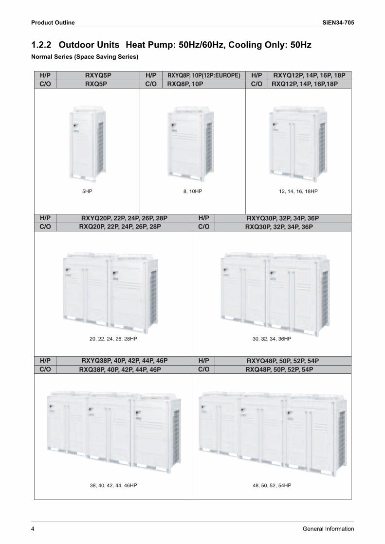
1.2.2 Outdoor Units Heat Pump: 50Hz/60Hz, Cooling Only: 50HzNormal Series (Space Saving Series)
RXYQ5P RXYQ8P, 10P (12P: EUROPE)
RXYQ48P, 50P, 52P, 54P
RXYQ12P, 14P, 16P, 18P
5HP 8, 10HP 12, 14, 16, 18HP
20, 22, 24, 26, 28HP 30, 32, 34, 36HP
38, 40, 42, 44, 46HP 48, 50, 52, 54HP
RXYQ5P RXYQ8P, 10P(12P:EUROPE) RXYQ12P, 14P, 16P, 18PRXQ5P
H/PC/O
H/PC/O
H/PC/ORXQ8P, 10P RXQ12P, 14P, 16P,18P
RXYQ5P RXYQ8P, 10P (12P: EUROPE)H/PC/O
H/PC/O
RXYQ20P, 22P, 24P, 26P, 28PRXQ20P, 22P, 24P, 26P, 28P
RXYQ30P, 32P, 34P, 36PRXQ30P, 32P, 34P, 36P
RXYQ5P RXYQ8P, 10P (12P: EUROPE)H/PC/O
H/PC/O
RXYQ48P, 50P, 52P, 54PRXQ48P, 50P, 52P, 54P
RXYQ38P, 40P, 42P, 44P, 46PRXQ38P, 40P, 42P, 44P, 46P

SiEN34-705 Product Outline
General Information 5
High COP Series (Energy Saving Series)
16, 18HP 24, 26HP
28, 30HP
RXYQ36PH, 38PH, 40PH, 42PH, 44PH, 46PH, 48PH, 50PHRXQ36PH, 38PH, 40PH, 42PH, 44PH, 46PH, 48PH, 50PH
32, 34HP
36, 38, 40, 42, 44, 46, 48, 50HP
RXYQ5P RXYQ8P, 10P (12P: EUROPE)RXYQ16PH, 18PHRXQ16PH, 18PH
RXYQ24PH, 26PHRXQ24PH, 26PH
RXYQ5P RXYQ8P, 10P (12P: EUROPE)RXYQ28PH, 30PHRXQ28PH, 30PH
RXYQ32PH, 34PHRXQ32PH, 34PH
H/PC/O
H/PC/O
H/PC/O
H/PC/O
H/PC/O

Product Outline SiEN34-705
6 General Information
1.3 Combination of Outdoor UnitsNormal Series (Space Saving Series)
Note: For multiple connection of 20HP system or more, an optional Daikin Outdoor Unit Multi Connection Piping Kit is required.
System Capacity
Number of units
Module Outdoor Unit Multi Connection Piping Kit (Option)5 8 10 12 14 16 18
5HP 1 l
�
8HP 1 l
10HP 1 l
12HP 1 l
14HP 1 l
16HP 1 l
18HP 1 l
20HP 2 l l
BHFP22P100
22HP 2 l l
24HP 2 l l
26HP 2 l l
28HP 2 l l
30HP 2 l l
32HP 2 ll
34HP 2 l l
36HP 2 ll
38HP 3 l l l
BHFP22P151
40HP 3 l ll
42HP 3 l l l
44HP 3 l ll
46HP 3 l ll
48HP 3 l ll
50HP 3 l ll
52HP 3 l ll
54HP 3 lll
SiEN34-705 Product Outline
General Information 7
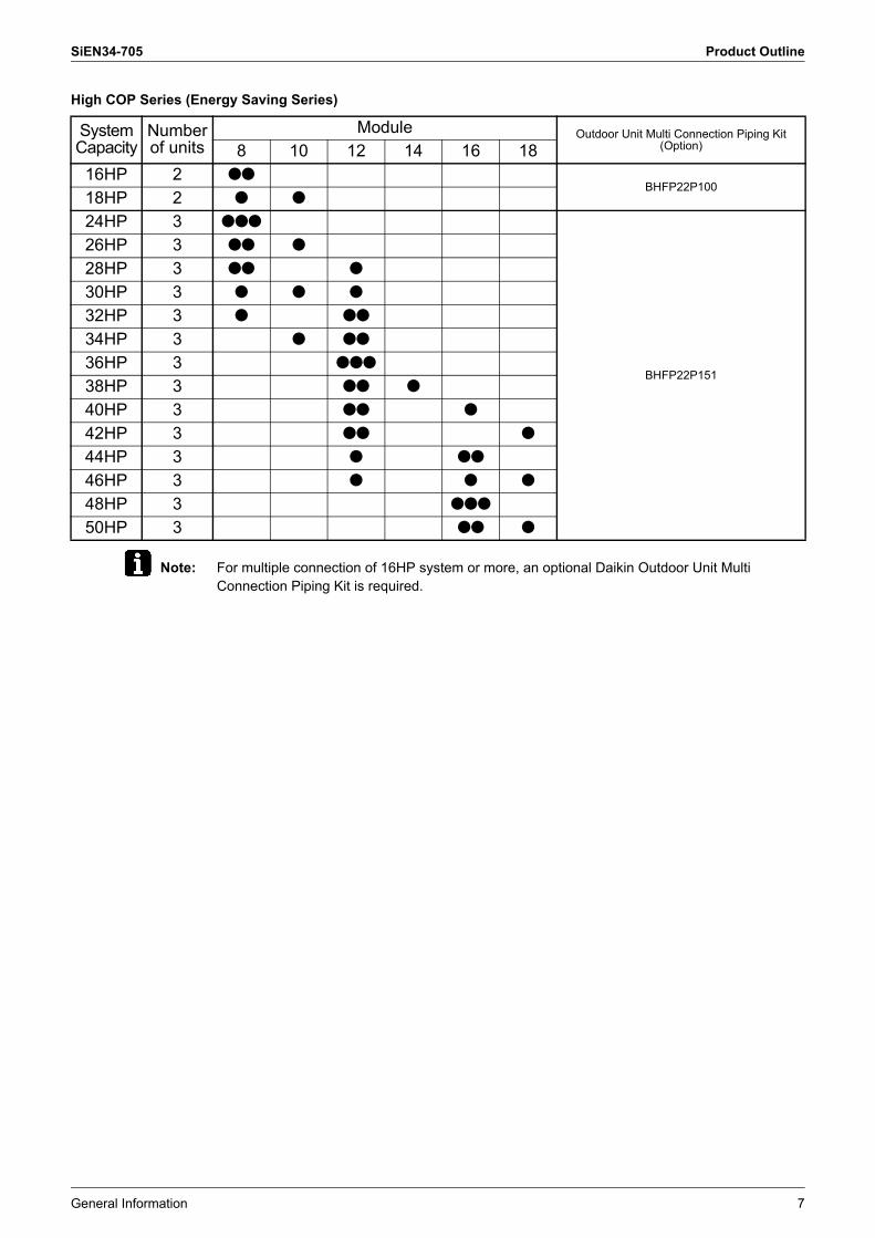
High COP Series (Energy Saving Series)
Note: For multiple connection of 16HP system or more, an optional Daikin Outdoor Unit Multi Connection Piping Kit is required.
System Capacity
Number of units
Module Outdoor Unit Multi Connection Piping Kit (Option)8 10 12 14 16 18
16HP 2 llBHFP22P100
18HP 2 l l
24HP 3 lll
BHFP22P151
26HP 3 ll l
28HP 3 ll l
30HP 3 l l l
32HP 3 l ll
34HP 3 l ll
36HP 3 lll
38HP 3 ll l
40HP 3 ll l
42HP 3 ll l
44HP 3 l ll
46HP 3 l l l
48HP 3 lll
50HP 3 ll l
Product Outline SiEN34-705
8 General Information
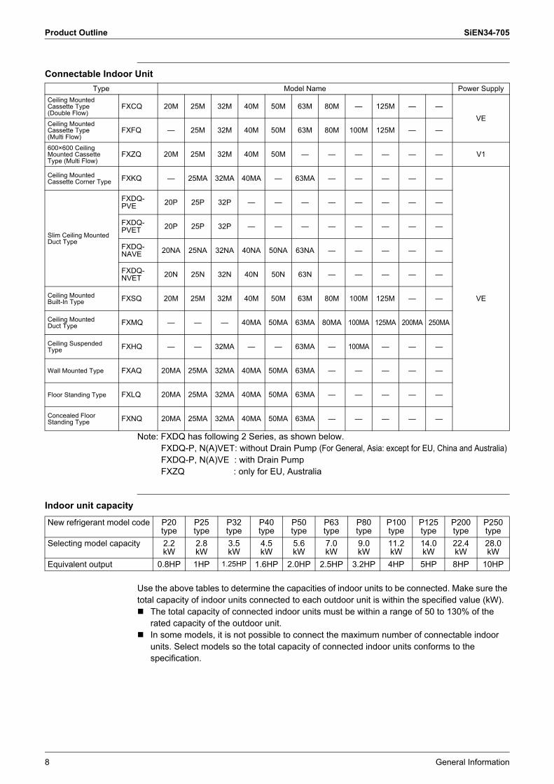
Connectable Indoor Unit
Note: FXDQ has following 2 Series, as shown below.FXDQ-P, N(A)VET: without Drain Pump (For General, Asia: except for EU, China and Australia)FXDQ-P, N(A)VE : with Drain Pump FXZQ : only for EU, Australia
Indoor unit capacity
Use the above tables to determine the capacities of indoor units to be connected. Make sure the total capacity of indoor units connected to each outdoor unit is within the specified value (kW).! The total capacity of connected indoor units must be within a range of 50 to 130% of the
rated capacity of the outdoor unit.! In some models, it is not possible to connect the maximum number of connectable indoor
units. Select models so the total capacity of connected indoor units conforms to the specification.
Type Model Name Power SupplyCeiling Mounted Cassette Type (Double Flow)
FXCQ 20M 25M 32M 40M 50M 63M 80M � 125M � �VE
Ceiling Mounted Cassette Type(Multi Flow)
FXFQ � 25M 32M 40M 50M 63M 80M 100M 125M � �
600×600 Ceiling Mounted Cassette Type (Multi Flow)
FXZQ 20M 25M 32M 40M 50M � � � � � � V1
Ceiling Mounted Cassette Corner Type FXKQ � 25MA 32MA 40MA � 63MA � � � � �
VE
Slim Ceiling Mounted Duct Type
FXDQ-PVE 20P 25P 32P � � � � � � � �
FXDQ-PVET 20P 25P 32P � � � � � � � �
FXDQ-NAVE 20NA 25NA 32NA 40NA 50NA 63NA � � � � �
FXDQ-NVET 20N 25N 32N 40N 50N 63N � � � � �
Ceiling Mounted Built-In Type FXSQ 20M 25M 32M 40M 50M 63M 80M 100M 125M � �
Ceiling Mounted Duct Type FXMQ � � � 40MA 50MA 63MA 80MA 100MA 125MA 200MA 250MA
Ceiling Suspended Type FXHQ � � 32MA � � 63MA � 100MA � � �
Wall Mounted Type FXAQ 20MA 25MA 32MA 40MA 50MA 63MA � � � � �
Floor Standing Type FXLQ 20MA 25MA 32MA 40MA 50MA 63MA � � � � �
Concealed Floor Standing Type FXNQ 20MA 25MA 32MA 40MA 50MA 63MA � � � � �
New refrigerant model code P20 type
P25 type
P32 type
P40 type
P50 type
P63 type
P80 type
P100 type
P125 type
P200 type
P250 type
Selecting model capacity 2.2kW
2.8kW
3.5kW
4.5kW
5.6kW
7.0kW
9.0kW
11.2kW
14.0kW
22.4kW
28.0kW
Equivalent output 0.8HP 1HP 1.25HP 1.6HP 2.0HP 2.5HP 3.2HP 4HP 5HP 8HP 10HP
SiEN34-705 Product Outline
General Information 9
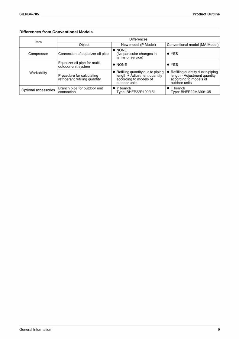
Differences from Conventional Models
ItemDifferences
Object New model (P Model) Conventional model (MA Model)
Compressor Connection of equalizer oil pipe" NONE
(No particular changes in terms of service)
" YES
Workability
Equalizer oil pipe for multi-outdoor-unit system " NONE " YES
Procedure for calculating refrigerant refilling quantity
" Refilling quantity due to piping length + Adjustment quantity according to models of outdoor units
" Refilling quantity due to piping length - Adjustment quantity according to models of outdoor units
Optional accessories Branch pipe for outdoor unit connection
" Y branchType: BHFP22P100/151
" T branchType: BHFP22MA90/135

Product Outline SiEN34-705
10 General Information
1.4 Model SelectionVRV III Heat Pump: 50Hz/60Hz, Cooling Only: 50Hz
Connectable indoor units number and capacityNormal Series
HP 5HP 8HP 10HP 12HP 14HP 16HP 18HPSystem name RX(Y)Q5P RX(Y)Q8P RX(Y)Q10P RX(YQ12P RX(YQ14P RX(YQ16P RX(YQ18POutdoor unit 1 RX(Y)Q5P RX(Y)Q8P RX(Y)Q10P RX(Y)Q12P RX(Y)Q14P RX(Y)Q16P RX(Y)Q18POutdoor unit 2 � � � � � � �Outdoor unit 3 � � � � � � �Total number of connectableindoor units 8 13 16 19 23 26 29
Total capacity of connectableindoor units (kW) 7.00~18.20 11.20~29.12 14.00~36.40 16.75~43.55 20.00~52.00 22.40~58.24 25.20~65.52
HP 20HP 22HP 24HP 26HP 28HP 30HP 32HPSystem name RX(Y)Q20P RX(Y)Q22P RX(Y)Q24P RX(Y)Q26P RX(Y)Q28P RX(Y)Q30P RX(Y)Q32POutdoor unit 1 RX(Y)Q8P RX(Y)Q10P RX(Y)Q8P RX(Y)Q8P RX(Y)Q10P RX(Y)Q12P RX(Y)Q16POutdoor unit 2 RX(Y)Q12P RX(Y)Q12P RX(Y)Q16P RX(Y)Q18P RX(Y)Q18P RX(Y)Q18P RX(Y)Q16POutdoor unit 3 � � � � � � �Total number of connectableindoor units 32 35 39 42 45 48 52
Total capacity of connectableindoor units (kW) 27.95~72.67 30.75~79.95 33.60~87.36 36.40~94.64 39.15~101.79 41.95~109.07 44.70~116.22
HP 34HP 36HP 38HP 40HP 42HP 44HP 46HPSystem name RX(Y)Q34P RX(Y)Q36P RX(Y)Q38P RX(Y)Q40P RX(Y)Q42P RX(Y)Q44P RX(Y)Q46POutdoor unit 1 RX(Y)Q16P RX(Y)Q18P RX(Y)Q8P RX(Y)Q8P RX(Y)Q8P RX(Y)Q8P RX(Y)Q10POutdoor unit 2 RX(Y)Q18P RX(Y)Q18P RX(Y)Q12P RX(Y)Q16P RX(Y)Q16P RX(Y)Q18P RX(Y)Q18POutdoor unit 3 � � RX(Y)Q18P RX(Y)Q16P RX(Y)Q18P RX(Y)Q18P RX(Y)Q18PTotal number of connectableindoor units 55 58 61 64
Total capacity of connectableindoor units (kW) 47.50~123.50 50.25~130.65 53.50~139.10 56.00~145.60 58.00~150.80 61.75~160.55 63.75~165.75
HP 48HP 50HP 52HP 54HPSystem name RX(Y)Q48P RX(Y)Q50P RX(Y)Q52P RX(Y)Q54POutdoor unit 1 RX(Y)Q12P RX(Y)Q14P RX(Y)Q16P RX(Y)Q18POutdoor unit 2 RX(Y)Q18P RX(Y)Q18P RX(Y)Q18P RX(Y)Q18POutdoor unit 3 RX(Y)Q18P RX(Y)Q18P RX(Y)Q18P RX(Y)Q18PTotal number of connectableindoor units 64
Total capacity of connectableindoor units (kW) 67.50~175.50 69.50~180.70 71.50~185.90 73.50~191.10
SiEN34-705 Product Outline
General Information 11
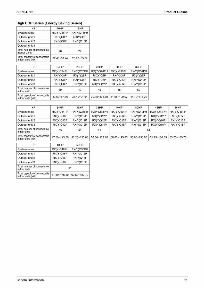
High COP Series (Energy Saving Series)HP 16HP 18HP
System name RX(Y)Q16PH RX(Y)Q18PHOutdoor unit 1 RX(Y)Q8P RX(Y)Q8POutdoor unit 2 RX(Y)Q8P RX(Y)Q10POutdoor unit 3 � �Total number of connectableindoor units 26 29
Total capacity of connectableindoor units (kW) 22.40~58.24 25.20~65.52
HP 24HP 26HP 28HP 30HP 32HPSystem name RX(Y)Q24PH RX(Y)Q26PH RX(Y)Q28PH RX(Y)Q30PH RX(Y)Q32PHOutdoor unit 1 RX(Y)Q8P RX(Y)Q8P RX(Y)Q8P RX(Y)Q8P RX(Y)Q8POutdoor unit 2 RX(Y)Q8P RX(Y)Q8P RX(Y)Q8P RX(Y)Q10P RX(Y)Q12POutdoor unit 3 RX(Y)Q8P RX(Y)Q10P RX(Y)Q12P RX(Y)Q12P RX(Y)Q12PTotal number of connectableindoor units 39 42 45 48 52
Total capacity of connectableindoor units (kW) 33.60~87.36 36.40~94.64 39.15~101.79 41.95~109.07 44.70~116.22
HP 34HP 36HP 38HP 40HP 42HP 44HP 46HPSystem name RX(Y)Q34PH RX(Y)Q36PH RX(Y)Q38PH RX(Y)Q40PH RX(Y)Q42PH RX(Y)Q44PH RX(Y)Q46PHOutdoor unit 1 RX(Y)Q10P RX(Y)Q12P RX(Y)Q12P RX(Y)Q12P RX(Y)Q12P RX(Y)Q12P RX(Y)Q12POutdoor unit 2 RX(Y)Q12P RX(Y)Q12P RX(Y)Q12P RX(Y)Q12P RX(Y)Q12P RX(Y)Q16P RX(Y)Q16POutdoor unit 3 RX(Y)Q12P RX(Y)Q12P RX(Y)Q14P RX(Y)Q16P RX(Y)Q18P RX(Y)Q16P RX(Y)Q18PTotal number of connectableindoor units 55 58 61 64
Total capacity of connectableindoor units (kW) 47.50~123.50 50.25~130.65 53.50~139.10 56.00~145.60 58.00~150.80 61.75~160.55 63.75~165.75
HP 48HP 50HPSystem name RX(Y)Q48PH RX(Y)Q50PHOutdoor unit 1 RX(Y)Q16P RX(Y)Q16POutdoor unit 2 RX(Y)Q16P RX(Y)Q16POutdoor unit 3 RX(Y)Q16P RX(Y)Q18PTotal number of connectableindoor units 64
Total capacity of connectableindoor units (kW) 67.50~175.50 69.50~180.70
Points to Bear in Mind at the System Design SiEN34-705
12 General Information
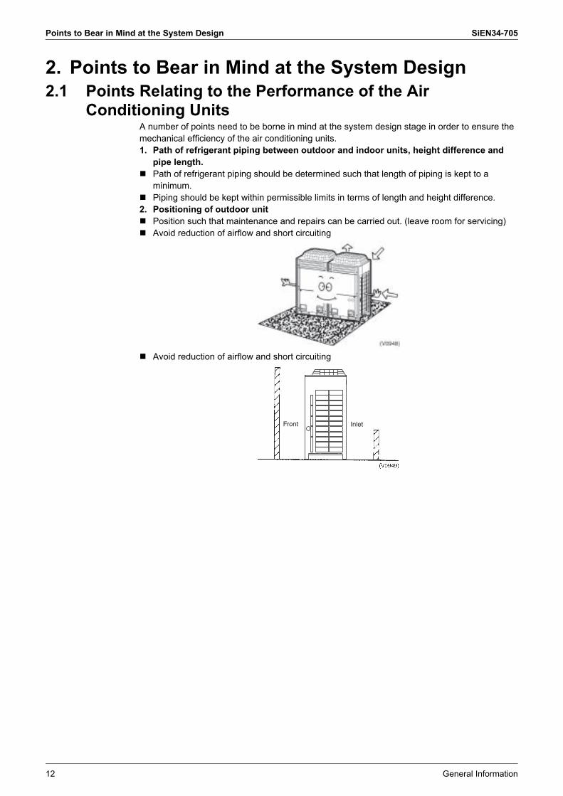
2. Points to Bear in Mind at the System Design2.1 Points Relating to the Performance of the Air
Conditioning UnitsA number of points need to be borne in mind at the system design stage in order to ensure the mechanical efficiency of the air conditioning units.1. Path of refrigerant piping between outdoor and indoor units, height difference and
pipe length.! Path of refrigerant piping should be determined such that length of piping is kept to a
minimum.! Piping should be kept within permissible limits in terms of length and height difference.2. Positioning of outdoor unit! Position such that maintenance and repairs can be carried out. (leave room for servicing)! Avoid reduction of airflow and short circuiting
! Avoid reduction of airflow and short circuiting
Front Inlet
SiEN34-705 Points to Bear in Mind at the System Design
General Information 13
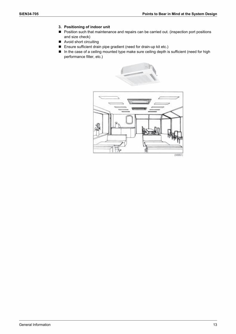
3. Positioning of indoor unit! Position such that maintenance and repairs can be carried out. (inspection port positions
and size check)! Avoid short circuiting! Ensure sufficient drain pipe gradient (need for drain-up kit etc.)! In the case of a ceiling mounted type make sure ceiling depth is sufficient (need for high
performance filter, etc.)
Points to Bear in Mind at the System Design SiEN34-705
14 General Information
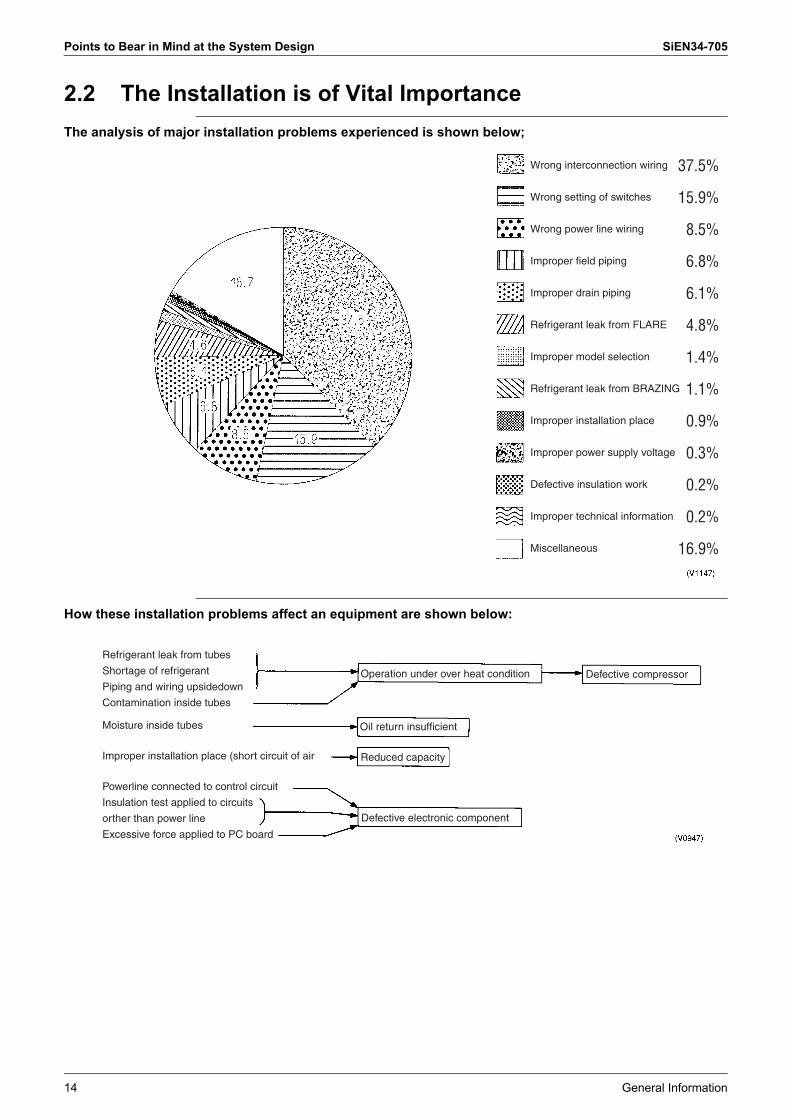
2.2 The Installation is of Vital ImportanceThe analysis of major installation problems experienced is shown below;
How these installation problems affect an equipment are shown below:
Wrong interconnection wiring
Wrong setting of switches
Wrong power line wiring
Improper field piping
Improper drain piping
Refrigerant leak from FLARE
Improper model selection
Refrigerant leak from BRAZING
Improper installation place
Improper power supply voltage
Defective insulation work
Improper technical information
Miscellaneous
37.5%
15.9%
8.5%
6.8%
6.1%
4.8%
1.4%
1.1%
0.9%
0.3%
0.2%
0.2%
16.9%
Refrigerant leak from tubes
Shortage of refrigerant
Piping and wiring upsidedown
Contamination inside tubes
Moisture inside tubes
Improper installation place (short circuit of air
Powerline connected to control circuit
Insulation test applied to circuits
orther than power line
Excessive force applied to PC board
Operation under over heat condition
Oil return insufficient
Reduced capacity
Defective electronic component
Defective compressor

SiEN34-705 Points to Bear in Mind at the System Design
General Information 15
2.3 Striking a Balance between System Installation and General Construction Work (Comprehensive Flow Chart)
Note: 1. The division of the work should be thoroughly clarified. (This applies particularly to work relating to the connection of control wiring, fitting of remote control and central control panel, boundary work on areas such as connection of drain piping and humidification supply piping, inspection and foundation)
2. Keep a constant check on the progress of the construction work to avoid deviations from the air conditioning work schedule.
3. For sleeve and insert work the positions of ceiling girders should be confirmed and sleeve and insert requirement, hole diameters, positioning and numbers decided. This is particularly important in the case of sleeves for drain piping.
Construction work
Air conditioning work
Determination of division of work
Settling operational details
Settling sleeve and insert work details
Fitting of steel sleeves
Molding box and reinforcement work
Removal of molding boxes
Ceiling preparations
Building rooftop cinder concrete
Preparation of contract drawings
Sleeve and insert work
Installation of indoor unit
Refrigerant piping work
Drain pipe work
Duct work
Heat insulation work
Electrical work
Installation of outdoor unit
Air tight test
Vacuum drying
Fit decoration panels
Test run
Transfer to customer with explanation
Additional charge of refrigerant
Outdoor unit foundation work
Energization
Cleaning inside and outside

Points to Bear in Mind at the System Design SiEN34-705
16 General Information
2.4 Points to Bear in Mind when Preparing the Contract Drawings
The following points should be borne in mind when preparing the contract drawings from the original drawings and the execution drawings.The contract drawings for the air conditioning system are blueprints for the performance of the necessary work which are drawn up on the basis of the original drawings in such a way that a working balance is achieved between the specific requirements of each individual aspect of the work.
Contract Drawing Objectives include:! The drawings should be easily comprehensible to those carrying out the work.! The contents of the drawings should not be subject to subsequent alteration.
The following is a list of the main points to be considered when preparing contract drawings for the III System and should be used as a reference during this stage of the work:
2.4.1 At the Contract Drawing Stage the Following Points are Critical!!
Contract drawing
Check pointsArrangement of units 1. Have you left the access passages clear and allowed sufficient room for servicing?
2. Have you taken full account of the possibility of short circuits? (Both indoor and outdoor units)3. Can the air filters be replaced easily?4. Have you indicated the size and location of the ceiling inspection ports? (Make sure there no other installations in
the area above)5. Have you taken into account the depth of the installation area? (In case of ceiling built-in type)6. Have you specified the position of the indoor unit clearly? (Have you taken full account of relevant features of the
local ventilation, humidity and lighting?)Refrigerant piping 1. Is the piping system correctly connected?
2. Are the rise and fall pipes correctly connected?3. Are the lengths and height differences of the pipes within the
recommended limits?Operational control 1. Are the interconnections between the piping and wiring of the
indoor and outdoor units clearly shown?2. Are the numbers of the local setting switches clearly shown?
(Group No. and Unit No.)3. Are the wiring connections between the remote control and the
centralized and remote controls clearly shown?Refer to the notes relating to the preparation of the control wiring system diagrams (see next page)
4. Are the different types of wires clearly marked?5. Are the any problems with the way the power supply cables and
control wiring have been separated or bound together?6. Are the inter-floor connections of the control wiring correct?7. Is the position of the remote control clearly marked?
Miscellaneous 1. Have you checked the gradient of the drain piping? (Must be at least 1/100)
(Example of a contract drawing)
Heat adjuster
Heating/cooling selector switch
Humidifying water supply pipe connection
SiEN34-705 Points to Bear in Mind at the System Design
General Information 17
2.4.2 Main Considerations in Preparation of Control Circuit DiagramsIn addition to the design of the appropriate this system configuration it is also essential that the control system be made amply clear. If the system is designed and installed without a clear, comprehensive plan then problems are inevitably going to occur during the test run.Servicing too will become much more time consuming than necessary. However, if control circuit diagrams are prepared along with the contract drawings in order to make the total system clearly visible then the essential points relating to the electrical connections will be easily understood, the test run will go off without a hitch and the whole system will be rendered fully effective.
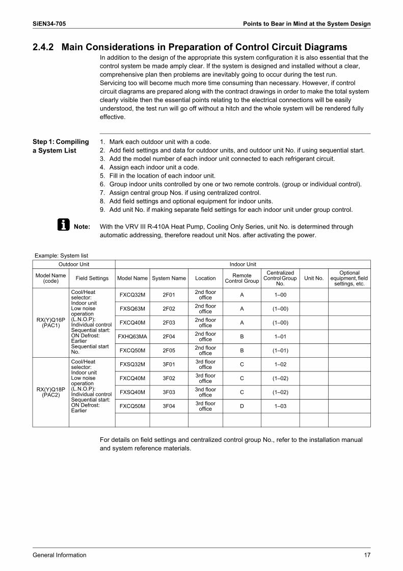
Step 1: Compiling a System List
1. Mark each outdoor unit with a code.2. Add field settings and data for outdoor units, and outdoor unit No. if using sequential start.3. Add the model number of each indoor unit connected to each refrigerant circuit.4. Assign each indoor unit a code.5. Fill in the location of each indoor unit.6. Group indoor units controlled by one or two remote controls. (group or individual control).7. Assign central group Nos. if using centralized control.8. Add field settings and optional equipment for indoor units.9. Add unit No. if making separate field settings for each indoor unit under group control.
Note: With the VRV III R-410A Heat Pump, Cooling Only Series, unit No. is determined through automatic addressing, therefore readout unit Nos. after activating the power.
For details on field settings and centralized control group No., refer to the installation manual and system reference materials.
Example: System listOutdoor Unit Indoor Unit
Model Name (code) Field Settings Model Name System Name Location Remote
Control GroupCentralized
Control Group No.
Unit No.Optional
equipment, field settings, etc.
RX(Y)Q16P (PAC1)
Cool/Heat selector: Indoor unitLow noise operation (L.N.O.P): Individual control Sequential start: ON Defrost: Earlier Sequential start No.
FXCQ32M 2F01 2nd floor office A 1�00
FXSQ63M 2F02 2nd floor office A (1�00)
FXCQ40M 2F03 2nd floor office A (1�00)
FXHQ63MA 2F04 2nd floor office B 1�01
FXCQ50M 2F05 2nd floor office B (1�01)
RX(Y)Q18P (PAC2)
Cool/Heat selector: Indoor unit Low noise operation (L.N.O.P): Individual control Sequential start: ON Defrost: Earlier
FXSQ32M 3F01 3rd floor office C 1�02
FXCQ40M 3F02 3rd floor office C (1�02)
FXSQ40M 3F03 3nd floor office C (1�02)
FXCQ50M 3F04 3rd floor office D 1�03
Points to Bear in Mind at the System Design SiEN34-705
18 General Information
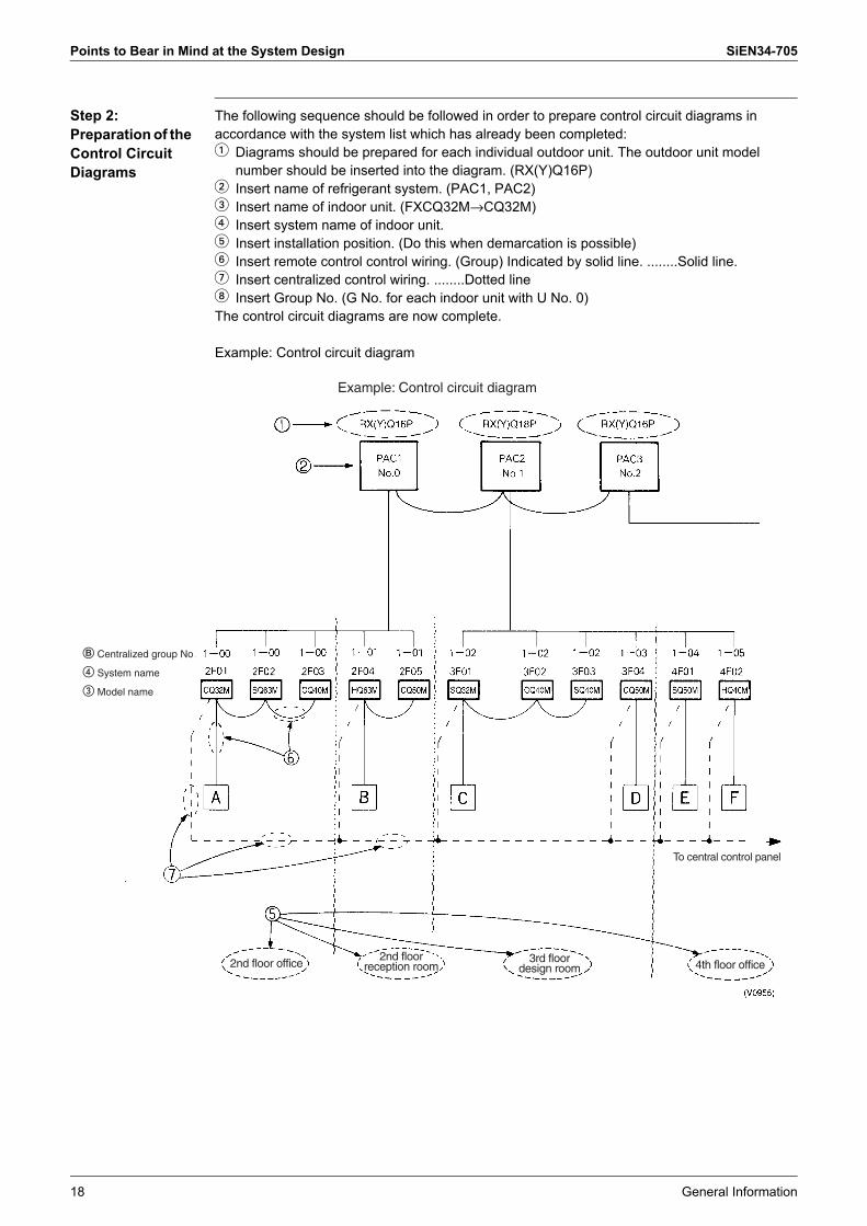
Step 2: Preparation of the Control Circuit Diagrams
The following sequence should be followed in order to prepare control circuit diagrams in accordance with the system list which has already been completed:1 Diagrams should be prepared for each individual outdoor unit. The outdoor unit model
number should be inserted into the diagram. (RX(Y)Q16P)2 Insert name of refrigerant system. (PAC1, PAC2)3 Insert name of indoor unit. (FXCQ32M→CQ32M)4 Insert system name of indoor unit.5 Insert installation position. (Do this when demarcation is possible)6 Insert remote control control wiring. (Group) Indicated by solid line. ........Solid line.7 Insert centralized control wiring. ........Dotted line8 Insert Group No. (G No. for each indoor unit with U No. 0)The control circuit diagrams are now complete.
Example: Control circuit diagram
Example: Control circuit diagram
� Centralized group No
� System name
� Model name
2nd floor office2nd floor
reception room3rd floor
design room 4th floor office
To central control panel

SiEN34-705 Installation
General Information 19
3. Installation3.1 Step by Step Installation Procedure
The above list indicates the order in which the individual work operations are normally carried out but this order may be varied where local conditions warrant such a change
Determination of division of work
Preparation of contract drawings
Sleeve and insert work
Installation of indoor unit
Refrigerant piping work
Drain pipe work
Duct work
Heat insulation work
Prework
Work
< Operations > < Points>
Indicate clearly who is to be responsible for switch settings.
Make relationship between outdoor, indoor, remote control and option connections clear. (Prepare control diagrams).
Take account of gradient of drain piping.
Check model name to make sure the fitting is made correctly.
Special attention to dryness, cleanness and tightness.
Adjust to downward gradient.
Make sure airflow is sufficient.
Make sure no gaps are left where the insulating materials are joined.
Multiple core cable must not be used. (Suitable cable
should be selected).
Must be carried out in strict accordance with control circuit diagrams.
The foundation must be level.
Avoid short circuits and ensure sufficient space is allowed for servicing.
Must be carried out in strict accordance with control circuit diagrams(Sequence start, low noise input, Cooling/Heating selection refrigerant piping lenght etc.).
In the final check for 24 hours at 3.80 MPa there must be no drop in pressure.
The vacuum pump used must have a capacity of reaching at least 5mmHg
The amount of refrigerant to be added to the unit should be calculated and written on th “Added Refrigerant” plate and attached to the rear side of the front cover.
Make sure there are no gaps left between the decoration panel and ceiling
Run each indoor unit in turn to make sure the pipework has been fitted correctly
Explain the use of the system as clearly as possible to your customer and make sure all relevant documentation
Electrical work (connection circuits and drive circuits)
Setting of indoor unit setting switches
Outdoor unit foundation work
Installation of outdoor unit
Setting of outdoor unit setting switch
Air tight test
Vacuum drying
Additional charge of refrigerant
Fit decoration panels
Test run adjustment
Transfer to customer with explana-tion
Installation SiEN34-705
20 General Information
3.2 Work Involved in Individual Operations and Points to be Borne in Mind
3.2.1 Sleeve and Insert Work! Operational steps
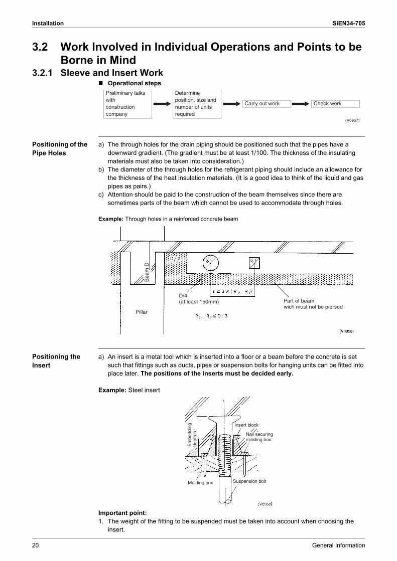
Positioning of the Pipe Holes
a) The through holes for the drain piping should be positioned such that the pipes have a downward gradient. (The gradient must be at least 1/100. The thickness of the insulating materials must also be taken into consideration.)
b) The diameter of the through holes for the refrigerant piping should include an allowance for the thickness of the heat insulation materials. (It is a good idea to think of the liquid and gas pipes as pairs.)
c) Attention should be paid to the construction of the beam themselves since there are sometimes parts of the beam which cannot be used to accommodate through holes.
Example: Through holes in a reinforced concrete beam
Positioning the Insert
a) An insert is a metal tool which is inserted into a floor or a beam before the concrete is set such that fittings such as ducts, pipes or suspension bolts for hanging units can be fitted into place later. The positions of the inserts must be decided early.
Example: Steel insert
Important point:1. The weight of the fitting to be suspended must be taken into account when choosing the
insert.
Preliminary talks withconstruction company
Determine position, size and number of units required
Carry out work Check work
(V0957)
Pillar
D/4(at least 150mm) Part of beam
wich must not be piersed
Bea
m D
Molding box Suspension bolt
Insert block
Nail securing molding box
Em
bedd
ing
dept
h h

SiEN34-705 Installation
General Information 21
3.2.2 Installation of Indoor Unit! Operational steps
Positioning 3 essential points when installing an indoor unit
1. Height: Take care to account for final ceiling facing surface level2. Level: Level fitting is essential. (within ±1 degree of horizontal)3. Direction: The unit must be fitted in line with the ultimately visible ceiling joints
Important points1. The suspension bolts must be strong enough to support the weight of the indoor unit.2. Optional features must be added to the indoor unit prior to installation.3. The model name should be checked prior to installation.4. Take care to align the main unit correctly. (Bearing in mind piping layout and direction of
blow out)5. Leave sufficient space for servicing to be carried out.6. Make inspection holes for model which need them.7. Fit the unit to ensure proper drainage.
Example: Ceiling mounted cassette type (FXCQ63M)
Determine installation position
Fit indoor unitMark installation position
Fit suspension bolts
(V0960)
Leave a gap of at least 3cm (leave pleanty of room)
Surface of ceiling facing
Surface of ceiling facing
Indoor unit
1500
or more
1500
or more
100 or more
100 or more
400
or m
ore
Installation SiEN34-705
22 General Information
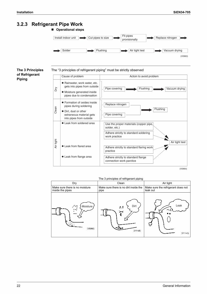
3.2.3 Refrigerant Pipe Work! Operational steps
The 3 Principles of Refrigerant Piping
The �3 principles of refrigerant piping� must be strictly observed
Fit pipes provisionally
Install indoor unit
Solder Flushing Air tight test Vacuum drying
Cut pipes to size Replace nitrogen
(V0963)
The 3 principles of refrigerant pipingDry Clean Air tight
Make sure there is no moisture inside the pipes
Make sure there is no dirt inside the pipe
Make sure the refrigerant does not leak out
Actoin to avoid problemCause of problem
� Rainwater, work water, etc. gets into pipes from outside
� Moisture generated inside pipes due to condensation
� Formation of oxides inside pipes during soldering
� Dirt, dust or other extraneous material gets into pipes from outside
� Leak from soldered area
� Leak from flared area
� Leak from flange area
Pipe covering Flushing
Replace nitrogen
Pipe covering
Air tight test
Flushing
Vacuum drying
Use the proper materials (copper pipe, solder, etc.)
Adhere strictly to standard soldering work practice
Adhere strictly to standard flaring work practice
Adhere strictly to standard flange connection work parctice
Cle
anD
ryA
ir tig
ht
(V0964)
Moisture Dirt Leak
SiEN34-705 Installation
General Information 23
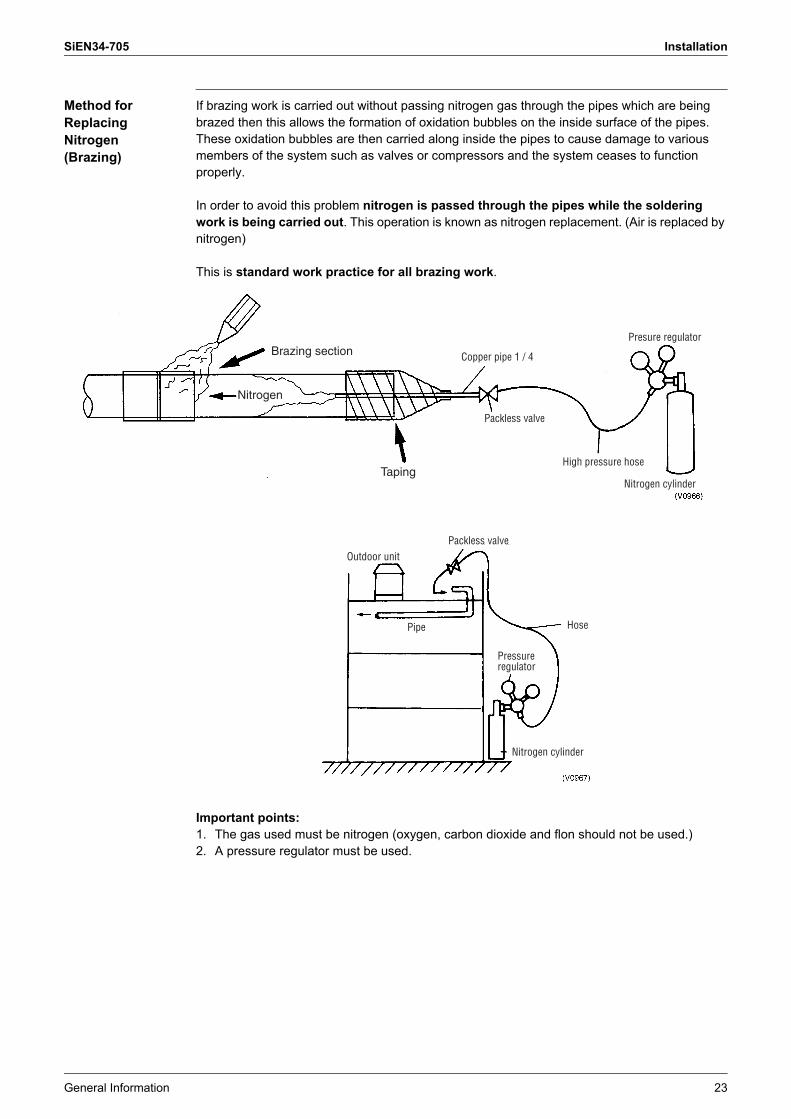
Method for Replacing Nitrogen (Brazing)
If brazing work is carried out without passing nitrogen gas through the pipes which are being brazed then this allows the formation of oxidation bubbles on the inside surface of the pipes. These oxidation bubbles are then carried along inside the pipes to cause damage to various members of the system such as valves or compressors and the system ceases to function properly.
In order to avoid this problem nitrogen is passed through the pipes while the soldering work is being carried out. This operation is known as nitrogen replacement. (Air is replaced by nitrogen)
This is standard work practice for all brazing work.
Important points:1. The gas used must be nitrogen (oxygen, carbon dioxide and flon should not be used.)2. A pressure regulator must be used.
Brazing section
Nitrogen
Taping
Presure regulator
Copper pipe 1 / 4
Packless valve
High pressure hose
Nitrogen cylinder
Outdoor unitPackless valve
Pipe Hose
Pressure regulator
Nitrogen cylinder
Installation SiEN34-705
24 General Information
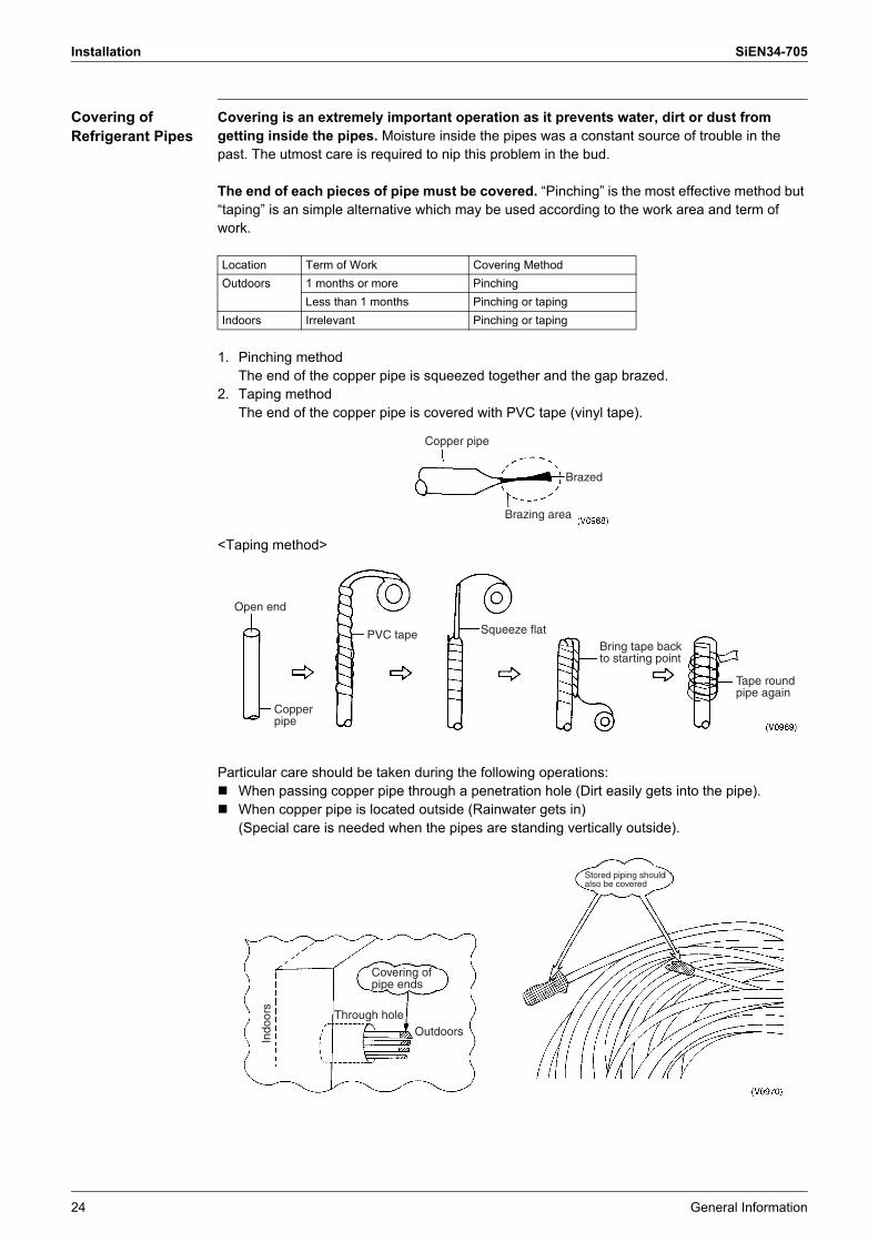
Covering of Refrigerant Pipes
Covering is an extremely important operation as it prevents water, dirt or dust from getting inside the pipes. Moisture inside the pipes was a constant source of trouble in the past. The utmost care is required to nip this problem in the bud.
The end of each pieces of pipe must be covered. �Pinching� is the most effective method but �taping� is an simple alternative which may be used according to the work area and term of work.
1. Pinching methodThe end of the copper pipe is squeezed together and the gap brazed.
2. Taping methodThe end of the copper pipe is covered with PVC tape (vinyl tape).
<Taping method>
Particular care should be taken during the following operations:! When passing copper pipe through a penetration hole (Dirt easily gets into the pipe).! When copper pipe is located outside (Rainwater gets in)
(Special care is needed when the pipes are standing vertically outside).
Location Term of Work Covering MethodOutdoors 1 months or more Pinching
Less than 1 months Pinching or tapingIndoors Irrelevant Pinching or taping
Copper pipe
Brazed
Brazing area
Copper pipe
Open end
Squeeze flatPVC tapeBring tape back to starting point
Tape round pipe again
OutdoorsThrough hole
Indo
ors
Stored piping should also be covered
Covering of pipe ends

SiEN34-705 Installation
General Information 25
Refrigerant Pipe Flushing
[3 major effects]1. Removal of oxidation bubbles formed inside copper pipes when �nitrogen replacement is
insufficient� during soldering work2. Removal of extraneous material and moisture from pipes when covering has been
insufficient3. Checks connections in pipes linking outdoor and indoor units (Both liquid and gas pipes)
[Example of procedure]1. Set pressure regulator on nitrogen cylinder.
∗The gas used must be nitrogen.(There is a danger of condensation if fleon or carbon dioxide are used and oxygen carries the risk of explosions.)
2. Connect the charge hose from the pressure regulator to the service port on the liquid pipe side of the outdoor unit.
3. Fit blanking plugs to all indoor units (B) other than unit A.
4. Open the main valve on the nitrogen cylinder and set the pressure regulator to 0.5MPa.
5. Check that the nitrogen is passing through the unit A liquid pipe.6. Flushing.! Block the end of the pipe with the insulation of your hand.↓! When the gas pressure becomes too great to contain remove insulation quickly. (First flush)↓! Block the end of the pipe with insulation again.↓(Carry out second flushing)
Flushing is a method of cleaning extraneous matter out of pipes using pressurized gas.
Pressure regulator
Outdoor unitGas pipe
Liquid pipe
Liquid pipeGas pipe
Blanking plug (brass)
Flare nutCopper pipe
Pressure regulatorNitrogen
Main valve
Primaryside
Secondary side
0.5 MPa
Wood
Gas pressure of 0.5 MPa
Insulation

Installation SiEN34-705
26 General Information
(The nature and amount of the extraneous material inside the pipe can be checked during flushing by placing a rag lightly over the end of the pipe. In the unlikely case that even a small quantity of moisture is found then the inside of the pipe should be dried out thoroughly.)Action:1. Flush the inside of the pipe with nitrogen gas. (Until such time as the moisture disappears.)2. Carry out a thorough vacuum drying operation. (See page 39)
1 Close the main valve on the nitrogen cylinder.2 Repeat the above operation for unit B.3 When the liquid pipe operations have been completed then do the same with the gas
pipes.
Choice of Materials for Refrigerant Piping
a) Refrigerant pipingSelection of piping material1. Foreign materials inside pipes (including oils for fabrication) must be 30mg/10m or less.2. Use the following material specification for refrigerant pipping:
� construction material: Phosphoric acid deoxidized seamless copper for refrigerant.� size: Determine the proper size referring to chapter �Example of connection�.� The wall thickness of the refrigerant piping should comply with relevant local and national
regulations. For R-410A the design pressure is 4.0 MPa.(40.8kgf/cm2).
3. Make sure to use the particular branches of piping that have been selected referring to chapter �Example of connection�.
4. The piping minimum thickness and material.* The min. thickness of the pipes shows the requirements of Japanese High Pressure Gas Control
low. (As of Jan. 2003)And the temper grade (#, 1/2H) shows the material type of JIS H 3300.The thickness and material should comply with relevant local and national regulations for the design pressure 4.0MPa (40bar).Select the wall thickness in accordance with relevant local and national regulations.
R-410ASize Temper grade Minimum thickness (mm)φ6.4 # 0.80φ9.5 # 0.80
φ12.7 # 0.80φ15.9 # 0.99φ19.1 1/2H 0.80φ22.2 1/2H 0.80φ25.4 1/2H 0.88φ28.6 1/2H 0.99φ31.8 1/2H 1.10φ34.9 1/2H 1.21φ38.1 1/2H 1.32φ41.3 1/2H 1.43

SiEN34-705 Installation
General Information 27
Equivalent piping length of joints and header (Reference)
b) Brazed joints and special branches1. General use (L bend joint, socket joint, T joint, etc.)! Joints must meet the requirements of the relevant JIS standard. (Size, materials, thickness,
etc.)2. Special branches! The Daikin outdoor unit multi connection kit, REFNET joint, REFNET header or Reducing
socket should be used.
Example: R-410A RXYQ-P Series
Refer detail of DAIKIN REFNET joint and REFNET header on page 161.
(Unit: mm)Pipe Size φ6.4 φ9.5 φ12.7 φ15.9 φ19.1 φ25.4 φ31.8 φ34.9 φ38.1 φ41.3L Joints
0.16 0.18 0.20 0.25 0.35 0.45 0.55 0.60 0.65 0.75
REFNET Joint
0.5
REFNET Header
1.0
REFNET header
4 branches
REFNET joint
Gas
pip
e(w
ith h
eat i
nsul
atio
n co
atin
g)
Liqu
id p
ipe
(with
hea
t ins
ulat
ion
coat
ing)
8 branches

Installation SiEN34-705
28 General Information
c) BrazingThe Multi-System requires only copper/copper jointing and the jointing method is explained below.! The use of �hard solder� is essential.
The R-410A Heat Pump, Cooling Only RX(Y)Q-P Series uses a wide range of piping sizes. You should therefore be careful when selecting the nozzle tip. If a small nozzle tip is used for brazing piping of large diameters such as φ38.1 and φ44.5, brazing flow becomes poor.
Table 1: Correlation of nozzle tip and size of refrigeration piping
Note: The values in the table above are for type B torch (French).
Type Solder:JIS mark
BCup-2(Phospor copper solder
BAg-2(Silver solder)
Soldering:temperature
(°C)
735
840
700
845
Breaking strengh
(kg/mm2)
Approx.25
Approx.25
Soldering method
Gas
Gas
Jointing distance
(mm)
0.05
0.2
0.05
0.2
Example for reference (product name)
Flux (example for reference)
Not required
Remarks
BCup-2 reacts easily with slufur to form a fragile water-soluble compound and should not therefore be used where the environment is not suitable.
Suitable for environments with a high sulfur contentH
ard
sold
er
This is used under normal conditions
6.4
9.5
12.7
15.9
19.1
22.2
25.4
28.6
31.8
34.9
38.1
41.3
Nozzle tip No.
1.6 2.4 3.2
(V0977)
Pip
ing
size
# 200 # 225 # 250 # 315 # 400 # 450 # 500
Brazing Rod diameter φ
SiEN34-705 Installation
General Information 29
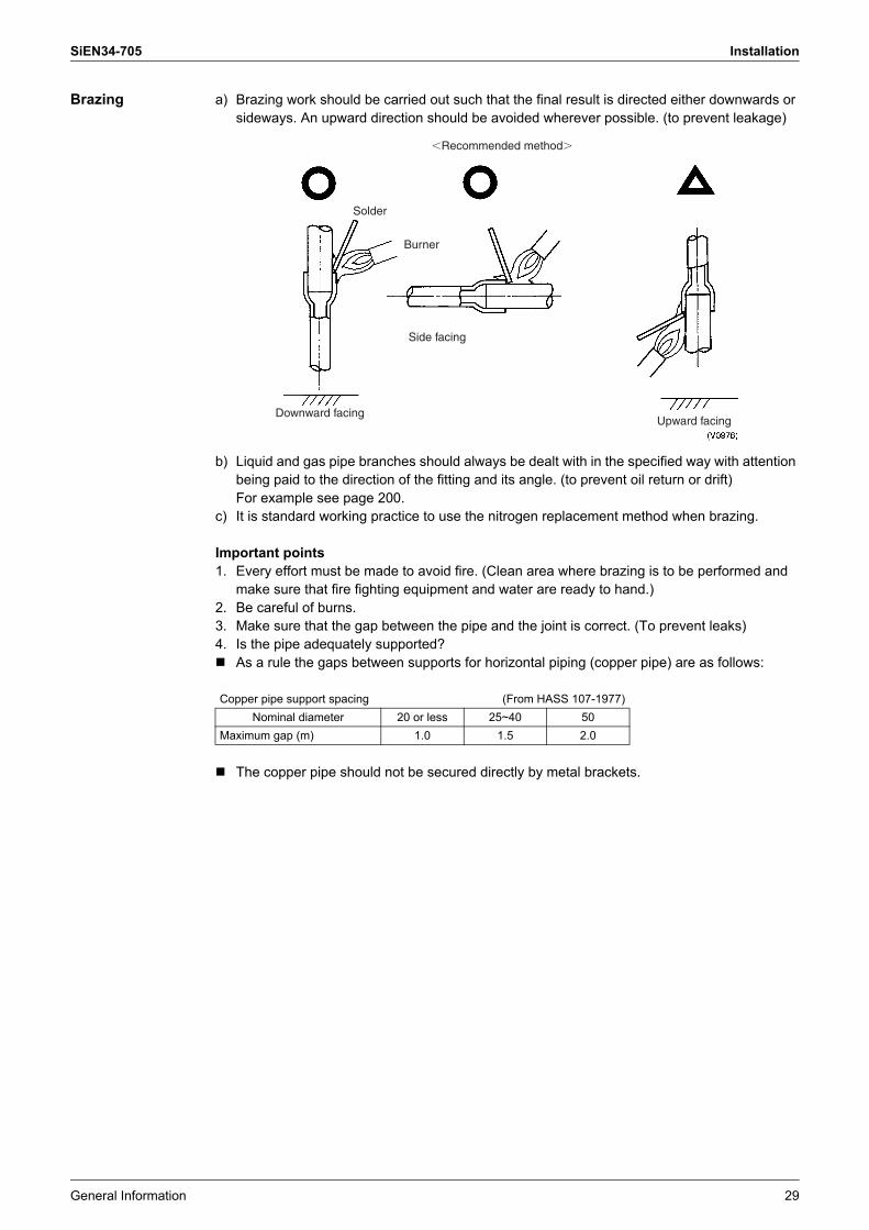
Brazing a) Brazing work should be carried out such that the final result is directed either downwards or sideways. An upward direction should be avoided wherever possible. (to prevent leakage)
b) Liquid and gas pipe branches should always be dealt with in the specified way with attention being paid to the direction of the fitting and its angle. (to prevent oil return or drift) For example see page 200.
c) It is standard working practice to use the nitrogen replacement method when brazing.
Important points1. Every effort must be made to avoid fire. (Clean area where brazing is to be performed and
make sure that fire fighting equipment and water are ready to hand.)2. Be careful of burns.3. Make sure that the gap between the pipe and the joint is correct. (To prevent leaks)4. Is the pipe adequately supported?! As a rule the gaps between supports for horizontal piping (copper pipe) are as follows:
! The copper pipe should not be secured directly by metal brackets.
Copper pipe support spacing (From HASS 107-1977)Nominal diameter 20 or less 25~40 50
Maximum gap (m) 1.0 1.5 2.0
�Recommended method�
Downward facing
Side facing
Burner
Solder
Upward facing

Installation SiEN34-705
30 General Information
Flare Connection (a) Stiffened pipe must always be annealed at least once prior to the flaring work.(b) A pipe cutter must be used to cut the pipe. (A large pipe cutter must be used where the pipe
has a large diameter. When cutting a pipe which is too big for the pipe cutter a metal saw may be used but care must be taken to ensure that the debris from sawing does not get into the pipe.)
(c) Set the flaring tool to make sure the flare size remains within the prescribed limits.
New Rank Compatible Flare ToolCompared to previous refrigerants, the components of a HFC refrigerant is small. R-410A also has a higher pressure than other refrigerants. Therefore, in order to strengthen the intensity of the form and size of the flare section used for R-410A (class 2) apparatus, unlike the specification of the conventional refrigerants, it was set up with different standards.When carrying out flare processing, use a new rank compatible flare tool or a conventional flare tool.
Flare Gauge (Adapter Corresponding to the New Rank)When using the later, use a flare gauge to take out the pipe from the gauge bar, adjust it, and then carry out the flare processing.
Size from the dice surface to the copper tip (in mm)
(d) Coat the inner and outer surface of the flare with refrigerator oil (Ester or ether oil). (this ensures that the flare nut passes smoothly, preventing the pipe from twisting.)Do not use SUNISO-4GS oil.
Nominal diameter External diameter of pipe d Pipe widening dimensions A1/4 6.35 9.13/8 9.52 13.21/2 12.7 16.65/8 15.88 19.73/4 19.05 24.0
Name Outer diameter
Wall thickness
Previous refrigerant (R-22, R-407C etc.) R-410AThe conventional flare tool The conventional flare tool
Clutch type Clutch type1/4� 6.35 0.8 0~0.5 1.0~1.53/8� 9.52 0.8 0~0.5 1.0~1.51/2� 12.70 0.8 0~0.5 1.0~1.55/8� 15.88 1.0 0~0.5 1.0~1.5
12mm×72mm1.0×0.5mm Each
Flare gauge
Size
Thickness
Oil Oil
SiEN34-705 Installation
General Information 31
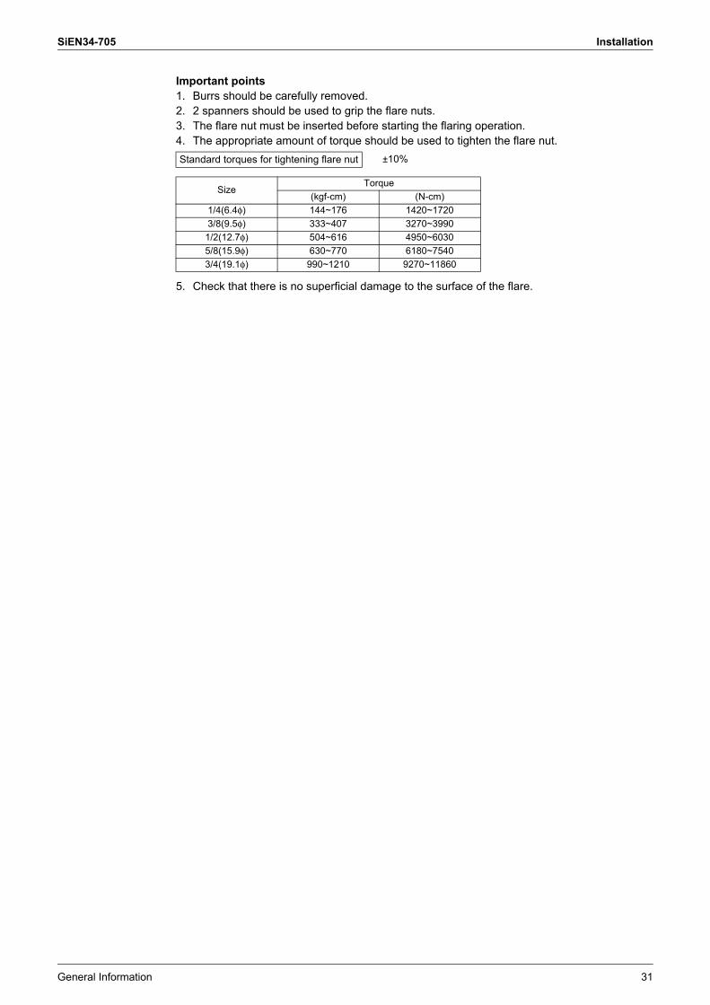
Important points1. Burrs should be carefully removed.2. 2 spanners should be used to grip the flare nuts.3. The flare nut must be inserted before starting the flaring operation.4. The appropriate amount of torque should be used to tighten the flare nut.
5. Check that there is no superficial damage to the surface of the flare.
Standard torques for tightening flare nut ±10%
SizeTorque
(kgf-cm) (N-cm)1/4(6.4φ) 144~176 1420~17203/8(9.5φ) 333~407 3270~3990
1/2(12.7φ) 504~616 4950~60305/8(15.9φ) 630~770 6180~75403/4(19.1φ) 990~1210 9270~11860

Installation SiEN34-705
32 General Information
Flaring Procedure
➀ Cut the pipe using a pipe cutter.
➁ The cut edge has burrs. (The amount of burrs becomes larger when the pipe wall is thick
➂ Remove the burrs using a file.(Be careful not to let particles enter the pipe. Point the pipe end downward during file
➃ Remove the burrs using a reamer.(Be careful not to let particles enter the pipe. Point the pipe end downward during cutting.)
➇ Apply refrigerant oil (Ester or ether oil) on the inside and outside of the flared section. (Do not apply SUNISO oil.)(Be careful to keep dust away.)
➆ Flare the pipe.Rotate the flaring tool 3 or 4 turns after a clicking sound is produced. This results in a clean flared surface.
➅ Before flaring, clean the cone section of the flaring tool.
Corn section
➄ Clean the inside of the pipe.(Use a thin stick with a cloth wrapped around it.)
SiEN34-705 Installation
General Information 33
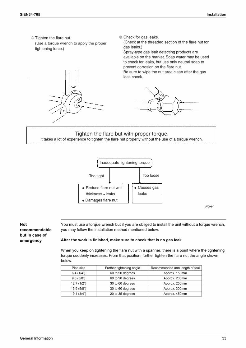
Not recommendable but in case of emergency
You must use a torque wrench but if you are obliged to install the unit without a torque wrench, you may follow the installation method mentioned below.
After the work is finished, make sure to check that is no gas leak.
When you keep on tightening the flare nut with a spanner, there is a point where the tightening torque suddenly increases. From that position, further tighten the flare nut the angle shown below:
➈ Tighten the flare nut.(Use a torque wrench to apply the proper tightening force.)
➉ Check for gas leaks.(Check at the threaded section of the flare nut for gas leaks.)Spray-type gas leak detecting products are available on the market. Soap water may be used to check for leaks, but use only neutral soap to prevent corrosion on the flare nut.Be sure to wipe the nut area clean after the gas leak check.
Tighten the flare but with proper torque.It takes a lot of experience to tighten the flare nut properly without the use of a torque wrench.
Inadequate tightening torque
Too tight Too loose
● Reduce flare nut wall
thickness ➞ leaks
● Damages flare nut
● Causes gas
leaks
Pipe size Further tightening angle Recommended arm length of tool6.4 (1/4�) 60 to 90 degrees Approx. 150mm9.5 (3/8�) 60 to 90 degrees Approx. 200mm
12.7 (1/2�) 30 to 60 degrees Approx. 250mm15.9 (5/8�) 30 to 60 degrees Approx. 300mm19.1 (3/4�) 20 to 35 degrees Approx. 450mm
Installation SiEN34-705
34 General Information
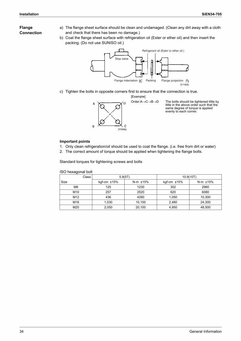
Flange Connection
a) The flange sheet surface should be clean and undamaged. (Clean any dirt away with a cloth and check that there has been no damage.)
b) Coat the flange sheet surface with refrigeration oil (Ester or ether oil) and then insert the packing. (Do not use SUNISO oil.)
c) Tighten the bolts in opposite corners first to ensure that the connection is true.
Important points1. Only clean refrigeration/oil should be used to coat the flange. (i.e. free from dirt or water)2. The correct amount of torque should be applied when tightening the flange bolts.
Standard torques for tightening screws and bolts
ISO hexagonal bolt
[Example]Order:A→C→B→D The bolts should be tightened little by
little in the above order such that the same degree of torque is applied evenly to each corner.
Class 5.8(5T) 10.9(10T)Size kgf-cm ±15% N-m ±15% kgf-cm ±15% N-m ±15%
M8 125 1230 302 2960M10 257 2520 620 6080M12 436 4280 1,050 10,300M16 1,030 10,100 2,480 24,300M20 2,050 20,100 4,950 48,500
Refrigerant oil (Ester or ether oil.)
Flange indentation Packing Flange projection
Stop valve

SiEN34-705 Installation
General Information 35
3.2.4 Thermal Insulation Work (Refrigerant Piping)! Operational steps
Materials The thermal insulation materials which are used must be well able to withstand the heat from the pipes.Example:Heat pump type: Heat resistant polyethylene foam (heat resistance of at least 120°C)Cooling only: Polyethylene foam (heat resistance of 100°C or more)
Essential Points of Thermal Insulation
The insulation of jointed areas such as the soldered, flared or flanged sections should only be carried out after the successful completion of the air tight test.The tips for insulation! Gas piping must be insulated.! Be sure to insulate the liquid-side and gas-side piping for the inter-unit piping and the
refrigerant branch kits and always use 18-type or better insulation for the oil pressure equalizer.
! Materials: Glass fiber or heat resistant polyethylene foam.Thickness: 10mm or moreHeat resistance: Gas pipe : 120°C or more / Liquid pipe : 70°C or more
! If you think the humidity around the cooling piping might exceed 30°C and RH80%, reinforce the insulation on the cooling piping (at least 20mm thick). Condensation might form on the surface of the insulation.
! Insulation of both liquid and gas pipe
Caution Be sure to size up the main gas line in the connecting piping of the suction gas piping if the equivalent length of the piping between the indoor and outdoor units exceeds 90m. In order to minimize the reduction of capacity caused by the pressure drop, the refrigerant pipe size may be sized up.
Refrigerant pipe work
Insulation(jointed areas)
Insulation (with the exception of the jointed areas)
Air tight test
(V0985)
Insulator
Finishing tape
Gas pipe
Electric cableLiquid pipe

Installation SiEN34-705
36 General Information
3.2.5 Air Tight Test! Operational steps
Essential Points of Testing (Maintaining Pressure Over a Period)
The key to successful testing is strict adherence to the following procedure:a) The liquid and gas piping in each refrigerant system should be pressurized in turn in
accordance with the following steps. (Nitrogen gas must be used.)
∗ Increasing the system pressure to 4.00MPa does not guarantee the identification of minor leaks if pressure is maintained for only a short time. It is therefore recommended that the system remain pressurized in accordance with Step 3 above for at least 24 hours.
Note: The pressure must on no account be increased beyond 4.00MPa.
Complete refrigerant pipe installation work
Pressurize Check for pressure drop Success
Locate and repair leaks(V0987)
! Step 1: increase pressure to 0.3MPa for 3 minutes or more ⎫
⎪⎬⎪⎭
⎫⎪⎬⎪⎭
Indicates existence of major leaks! Step 2: increase pressure to 1.5MPa for 3
minutes or more
Indicates existence of minor leaks! Step 3: increase pressure to 4.00MPa for
approx. 24 hours

SiEN34-705 Installation
General Information 37
b) Check for pressure dropIf there is no drop in pressure then the test is deemed a success.If the pressure drops then the leak must be located. See following page.However, if there is a change in the ambient temperature between the pressurizing stage and the time when you check for a drop in pressure then you will have to adjust your calculations accordingly since a change of 1°C can account for a pressure change of approximately 0.01MPa.Compensating adjustment value:(temperature at time of pressurizing � temperature at time of checking) × 0.01Example:Time of pressurizing: 4.00MPa 25°C24 hours later: 3.95MPa 20°CThe pressure drop in such a case is deemed to be zero (successful test).
Step 3 4.00 Mpa x 24hr
Step 2 15 Mpa x 5min
Step 1 0.3 Mpa x 3min
24 hours5 minutes
3 minutes
Installation SiEN34-705
38 General Information
Checking for Leaks
[Check 1] (Where pressure falls while carrying out Steps 1 to 3 described on previous page)! Check by ear......Listen for the sound of a major leak.! Check by hand......Check for leak by feeling around jointed sections with hand.! Soap and water check (∗Snoop)......Bubbles will reveal the presence of a leak.
[Check 2] (When searching for a minor leak or when there has been a fall in pressure while the system has been fully pressurized but the source of the leak cannot be traced.)1. Release the nitrogen until the pressure reaches 0.3MPa.2. Increase pressure to 1.5MPa using gaseous flon gas (R-410A). (Nitrogen and flon gas
mixed)3. Search for the source of the leak using a leak detector.4. If the source of the leak still cannot be traced then repressurize with nitrogen up to 4.00MPa
and check again. (The pressure must not be increased to more than 4.00MPa.)
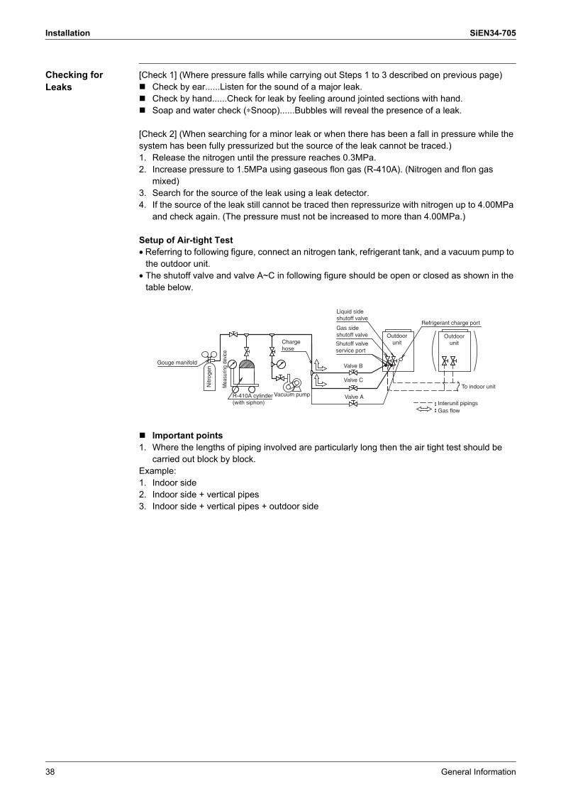
Setup of Air-tight Test• Referring to following figure, connect an nitrogen tank, refrigerant tank, and a vacuum pump to
the outdoor unit.• The shutoff valve and valve A~C in following figure should be open or closed as shown in the
table below.
! Important points1. Where the lengths of piping involved are particularly long then the air tight test should be
carried out block by block.Example:1. Indoor side2. Indoor side + vertical pipes3. Indoor side + vertical pipes + outdoor side
Gouge manifold
Charge hose
Vacuum pumpR-410A cylinder(with siphon)
Gas side shutoff valve
Shutoff valve service port
Valve B
Valve C
Valve A
Nitr
ogen
Mea
surin
g de
vice
Outdoor unit
Outdoor unit
Refrigerant charge port
To indoor unit
Interunit pipingsGas flow
Liquid side shutoff valve
SiEN34-705 Installation
General Information 39
3.2.6 Vacuum Drying
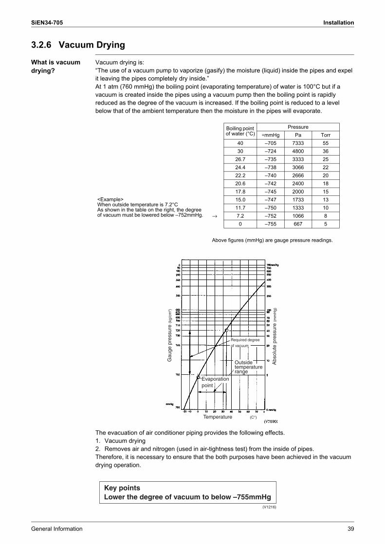
What is vacuum drying?
Vacuum drying is:�The use of a vacuum pump to vaporize (gasify) the moisture (liquid) inside the pipes and expel it leaving the pipes completely dry inside.�At 1 atm (760 mmHg) the boiling point (evaporating temperature) of water is 100°C but if a vacuum is created inside the pipes using a vacuum pump then the boiling point is rapidly reduced as the degree of the vacuum is increased. If the boiling point is reduced to a level below that of the ambient temperature then the moisture in the pipes will evaporate.
The evacuation of air conditioner piping provides the following effects.1. Vacuum drying2. Removes air and nitrogen (used in air-tightness test) from the inside of pipes.Therefore, it is necessary to ensure that the both purposes have been achieved in the vacuum drying operation.
<Example>When outside temperature is 7.2°CAs shown in the table on the right, the degree of vacuum must be lowered below �752mmHg.
Boiling point of water (°C)
Pressure∗mmHg Pa Torr
40 �705 7333 5530 �724 4800 36
26.7 �735 3333 2524.4 �738 3066 2222.2 �740 2666 2020.6 �742 2400 1817.8 �745 2000 1515.0 �747 1733 1311.7 �750 1333 10
→ 7.2 �752 1066 80 �755 667 5
Above figures (mmHg) are gauge pressure readings.
Required degree
of vacuum
Outside temperature range
Evaporation point
Gau
ge p
ress
ure
(kg/
cm2 )
Abs
olut
e pr
essu
re (m
mH
g)
Temperature (C°)
Key pointsLower the degree of vacuum to below –755mmHg
(V1216)
Installation SiEN34-705
40 General Information
Choosing a Vacuum Pump
GeneralRefrigerant piping content volume of the VRV III R-410A Series is larger than the VRV Inverter Series, and consequently takes more time for vacuum drying. If you have time to spare, you may use the same vacuum pump, but if you want to save time, you will have to use a pump with higher exhaust velocity (exhaust volume).
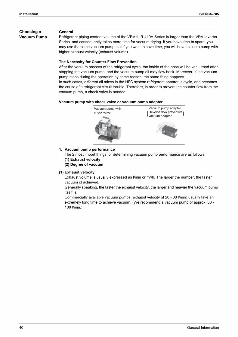
The Necessity for Counter Flow PreventionAfter the vacuum process of the refrigerant cycle, the inside of the hose will be vacuumed after stopping the vacuum pump, and the vacuum pump oil may flow back. Moreover, if the vacuum pump stops during the operation by some reason, the same thing happens.In such cases, different oil mixes in the HFC system refrigerant apparatus cycle, and becomes the cause of a refrigerant circuit trouble. Therefore, in order to prevent the counter flow from the vacuum pump, a check valve is needed.
Vacuum pump with check valve or vacuum pump adapter
1. Vacuum pump performanceThe 2 most import things for determining vacuum pump performance are as follows: (1) Exhaust velocity(2) Degree of vacuum
(1) Exhaust velocityExhaust volume is usually expressed as l/min or m³/h. The larger the number, the faster vacuum id achieved.Generally speaking, the faster the exhaust velocity, the larger and heavier the vacuum pump itself is. Commercially available vacuum pumps (exhaust velocity of 20 - 30 l/min) usually take an extremely long time to achieve vacuum. (We recommend a vacuum pump of approx. 60 - 100 l/min.)
Vacuum pump adapterReverse flow preventive vacuum adapter
Vacuum pump with check valve

SiEN34-705 Installation
General Information 41
(2) Degree of vacuumUltimate vacuum varies largely according to use of the vacuum pump. Vacuum pumps used for vacuum forming cannot be used for vacuum drying. (A vacuum pump with a high degree of vacuum is required.)
When selecting a vacuum, you should select one which is capable of achieving 0.2 Torr of ultimate vacuum.
Degree of vacuum is expressed in Torr, micron, mmHg, and Pascal (Pa). The units correlate as follows:
2. Vacuum pump maintenanceBecause of their nature, most vacuum pumps contain large amounts of oil which lubricates bearings, etc., and functions to enhance airtightness of pistons. When using a vacuum pump to discharge air from refrigerant piping, moisture in the air tends to get mixed in with the oil. You must therefore change oil periodically and make sure the proper oil level is maintained. (Perform periodic inspections in accordance with the operating instructions.)
3. Degree of vacuum measurementAn extremely accurate vacuum gauge is required to test degree of vacuum. You cannot accurately measure degree of vacuum with the compound gauge on the gauge manifold. A Pirani vacuum gauge is required to measure degree of vacuum accurately. Because Pirani gauges are very sensitive and require extreme care when using, they are not very suitable for use in the field. You should therefore use the Pirani gauge to calibrate the attached vacuum gauge on the gauge manifold and the degree of vacuum of the vacuum pump.
Unit Standard atmospheric pressure Perfect vacuumGauge Pressure kg/cm2 0 �1.033Absolute Pressure kg/cm2 abs 1.033 0Torr Torr 760 0Micron Micron 760000 0∗mmHg mmHg 0 760Pa hPa 1013.33 0
(V0992)
760 Torr
1013.33 hPa
0 mmHg
Standard atmospheric pressure760
5 Torr
667 Pa
755 mmHg
Vacuum target value5
0 Torr
0 Pa
760 mmHg
Perfect vacuum0 Torr
Degree of vacuum must be within the range expressed by
Installation SiEN34-705
42 General Information
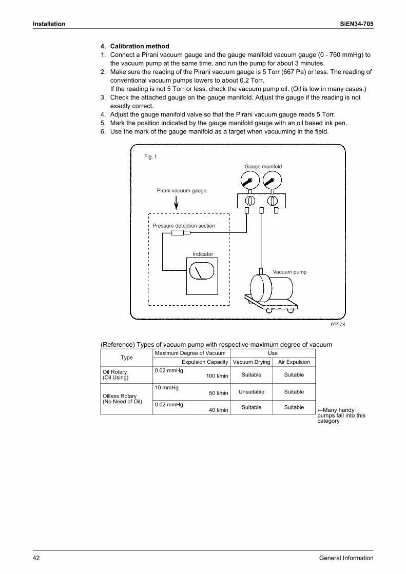
4. Calibration method1. Connect a Pirani vacuum gauge and the gauge manifold vacuum gauge (0 - 760 mmHg) to
the vacuum pump at the same time, and run the pump for about 3 minutes. 2. Make sure the reading of the Pirani vacuum gauge is 5 Torr (667 Pa) or less. The reading of
conventional vacuum pumps lowers to about 0.2 Torr.If the reading is not 5 Torr or less, check the vacuum pump oil. (Oil is low in many cases.)
3. Check the attached gauge on the gauge manifold. Adjust the gauge if the reading is not exactly correct.
4. Adjust the gauge manifold valve so that the Pirani vacuum gauge reads 5 Torr.5. Mark the position indicated by the gauge manifold gauge with an oil based ink pen.6. Use the mark of the gauge manifold as a target when vacuuming in the field.
(Reference) Types of vacuum pump with respective maximum degree of vacuum
TypeMaximum Degree of Vacuum Use
Expulsion Capacity Vacuum Drying Air Expulsion
Oil Rotary (Oil Using)
0.02 mmHg100 l/min Suitable Suitable
Oilless Rotary (No Need of Oil)
10 mmHg50 l/min Unsuitable Suitable
0.02 mmHg40 l/min Suitable Suitable ←Many handy
pumps fall into this category
Gauge manifold
Pirani vacuum gauge
Vacuum pump
Indicator
Pressure detection section
Fig. 1
SiEN34-705 Installation
General Information 43
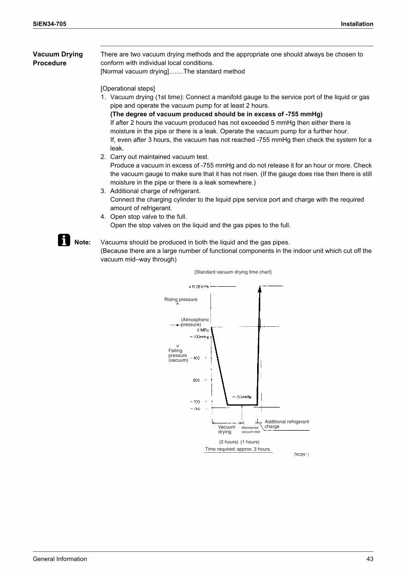
Vacuum Drying Procedure
There are two vacuum drying methods and the appropriate one should always be chosen to conform with individual local conditions.[Normal vacuum drying]........The standard method
[Operational steps]1. Vacuum drying (1st time): Connect a manifold gauge to the service port of the liquid or gas
pipe and operate the vacuum pump for at least 2 hours.(The degree of vacuum produced should be in excess of -755 mmHg)If after 2 hours the vacuum produced has not exceeded 5 mmHg then either there is moisture in the pipe or there is a leak. Operate the vacuum pump for a further hour.If, even after 3 hours, the vacuum has not reached -755 mmHg then check the system for a leak.
2. Carry out maintained vacuum test.Produce a vacuum in excess of -755 mmHg and do not release it for an hour or more. Check the vacuum gauge to make sure that it has not risen. (If the gauge does rise then there is still moisture in the pipe or there is a leak somewhere.)
3. Additional charge of refrigerant.Connect the charging cylinder to the liquid pipe service port and charge with the required amount of refrigerant.
4. Open stop valve to the full.Open the stop valves on the liquid and the gas pipes to the full.
Note: Vacuums should be produced in both the liquid and the gas pipes.(Because there are a large number of functional components in the indoor unit which cut off the vacuum mid�way through)
[Standard vacuum drying time chart]
Time required: approx. 3 hours.
Additional refrigerant charge
(Atmospheric pressure)
Failing pressure (vacuum)
Rising pressure
Vacuum drying
Maintained vacuum test
(2 hours) (1 hours)
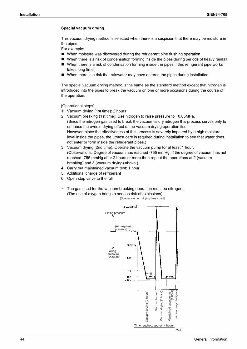
Installation SiEN34-705
44 General Information
Special vacuum drying
This vacuum drying method is selected when there is a suspicion that there may be moisture in the pipes.For example:! When moisture was discovered during the refrigerant pipe flushing operation! When there is a risk of condensation forming inside the pipes during periods of heavy rainfall! When there is a risk of condensation forming inside the pipes if this refrigerant pipe works
takes long time! When there is a risk that rainwater may have entered the pipes during installation
The special vacuum drying method is the same as the standard method except that nitrogen is introduced into the pipes to break the vacuum on one or more occasions during the course of the operation.
[Operational steps]1. Vacuum drying (1st time): 2 hours2. Vacuum breaking (1st time): Use nitrogen to raise pressure to +0.05MPa.
(Since the nitrogen gas used to break the vacuum is dry nitrogen this process serves only to enhance the overall drying effect of the vacuum drying operation itself. However, since the effectiveness of this process is severely impaired by a high moisture level inside the pipes, the utmost care is required during installation to see that water does not enter or form inside the refrigerant pipes.)
3. Vacuum drying (2nd time): Operate the vacuum pump for at least 1 hour.(Observations: Degree of vacuum has reached -755 mmHg. If the degree of vacuum has not reached -755 mmHg after 2 hours or more then repeat the operations at 2 (vacuum breaking) and 3 (vacuum drying) above.)
4. Carry out maintained vacuum test: 1 hour5. Additional charge of refrigerant6. Open stop valve to the full
∗ The gas used for the vacuum breaking operation must be nitrogen.(The use of oxygen brings a serious risk of explosions)
[Special vacuum drying time chart]
Time required: approx. 4 hours.
Add
ition
al c
harg
e of
ref
riger
ant
(Atmospheric pressure)
Failing pressure (vacuum)
Rising pressure
Vac
uum
dry
ing
(2 h
ours
)
Mai
ntai
ned
vacu
um te
st
(1 h
our)
Vac
uum
bro
ken
Vac
uum
dry
ing
(1 h
our)
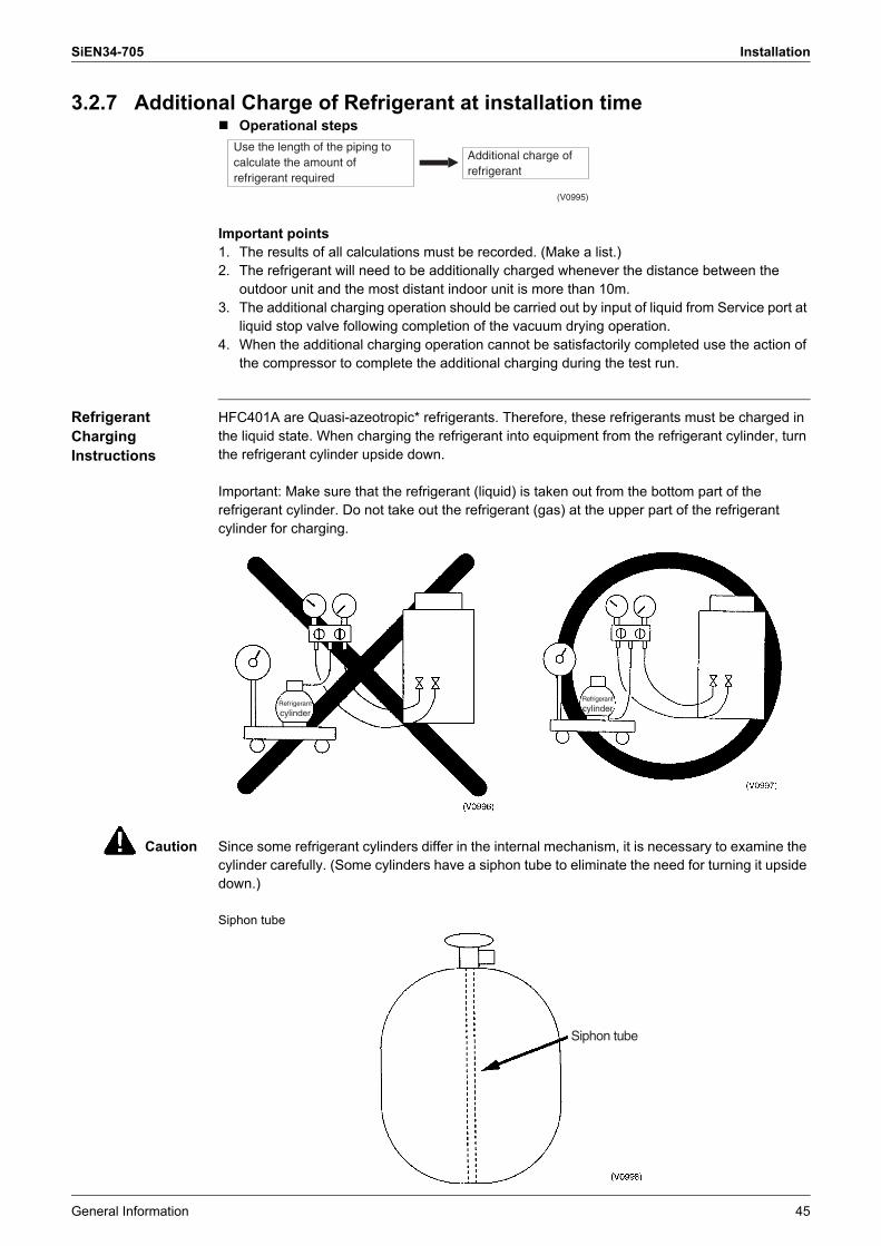
SiEN34-705 Installation
General Information 45
3.2.7 Additional Charge of Refrigerant at installation time! Operational steps
Important points1. The results of all calculations must be recorded. (Make a list.)2. The refrigerant will need to be additionally charged whenever the distance between the
outdoor unit and the most distant indoor unit is more than 10m.3. The additional charging operation should be carried out by input of liquid from Service port at
liquid stop valve following completion of the vacuum drying operation.4. When the additional charging operation cannot be satisfactorily completed use the action of
the compressor to complete the additional charging during the test run.
Refrigerant Charging Instructions
HFC401A are Quasi-azeotropic* refrigerants. Therefore, these refrigerants must be charged in the liquid state. When charging the refrigerant into equipment from the refrigerant cylinder, turn the refrigerant cylinder upside down.
Important: Make sure that the refrigerant (liquid) is taken out from the bottom part of the refrigerant cylinder. Do not take out the refrigerant (gas) at the upper part of the refrigerant cylinder for charging.
Caution Since some refrigerant cylinders differ in the internal mechanism, it is necessary to examine the cylinder carefully. (Some cylinders have a siphon tube to eliminate the need for turning it upside down.)
Siphon tube
Use the length of the piping to calculate the amount of refrigerant required
Additional charge of refrigerant
(V0995)
Refrigerant
cylinder
Refrigerant
cylinder
Siphon tube
Installation SiEN34-705
46 General Information
<*Non-azeotropic refrigerants or Quasi-azeotropic refrigerants>When a refrigerant is a mixture of two or more types with different evaporation temperature, it is called a non-azeotropic refrigerant. If all refrigerant components evaporate at the same temperature, the mixture is called an azeotropic refrigerant.If a non-azeotropic refrigerant is charged into equipment in the gaseous state, the refrigerant components that evaporate sooner than others enter the equipment, and the refrigerant that evaporate after others remain in the refrigerant cylinder.
* Quasi-azeotropic mixture refrigerant: mixture of two or more refrigerants having similar boiling points.
Caution itemsThe following devices designed for R-22 cannot be used to charge the new refrigerants. Be sure to use the devices specifically designed for the new refrigerants.1. Charging cylinder...(Pressure resisting specification is different.)2. Gauge manifold (including hose)...(same as above)
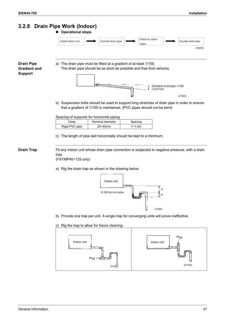
SiEN34-705 Installation
General Information 47
3.2.8 Drain Pipe Work (Indoor)! Operational steps
Drain Pipe Gradient and Support
a) The drain pipe must be fitted at a gradient of at least 1/100.The drain pipe should be as short as possible and free from airlocks.
b) Suspension bolts should be used to support long stretches of drain pipe in order to ensure that a gradient of 1/100 is maintained. (PVC pipes should not be bent)
Spacing of supports for horizontal piping
c) The length of pipe laid horizontally should be kept to a minimum.
Drain Trap Fit any indoor unit whose drain pipe connection is subjected to negative pressure, with a drain trap.(FXYMP40~125 only)
a) Rig the drain trap as shown in the drawing below.
b) Provide one trap per unit. A single trap for converging units will prove ineffective.
c) Rig the trap to allow for future cleaning.
Insulate drain pipeInstall indoor unit Connect drain pipeCheck for water
leaks
(V0999)
Class Nominal diameter SpacingRigid PVC pipe 25~40mm 1~1.5m
Gradient of at least 1/100(1cm/1m)
Indoor unit
H: 50 mm or more
Indoor unit
Plug
Indoor unit
Plug
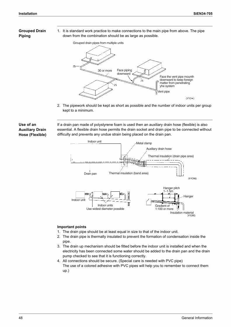
Installation SiEN34-705
48 General Information
Grouped Drain Piping
1. It is standard work practice to make connections to the main pipe from above. The pipe down from the combination should be as large as possible.
2. The pipework should be kept as short as possible and the number of indoor units per group kept to a minimum.
Use of an Auxiliary Drain Hose (Flexible)
If a drain pan made of polystyrene foam is used then an auxiliary drain hose (flexible) is also essential. A flexible drain hose permits the drain socket and drain pipe to be connected without difficulty and prevents any undue strain being placed on the drain pan.
Important points1. The drain pipe should be at least equal in size to that of the indoor unit.2. The drain pipe is thermally insulated to prevent the formation of condensation inside the
pipe.3. The drain up mechanism should be fitted before the indoor unit is installed and when the
electricity has been connected some water should be added to the drain pan and the drain pump checked to see that it is functioning correctly.
4. All connections should be secure. (Special care is needed with PVC pipe)The use of a colored adhesive with PVC pipes will help you to remember to connect them up.)
Grouped drain pipes from multiple units
Face piping downward
Face the vent pipe mounth downward to keep foreign matter from penetrating yhe system
Vent pipe
30 or more
Indoor unit
Thermal insulation (band area)Drain pan
Metal clamp
Thermal insulation (drain pipe area)
Auxiliary drain hose
Indoor unit
Indoor unitsUse widest diameter possible
Hanger pitch1~1.5m
Insulation material
Gradient of 1:100 or more
Hanger

SiEN34-705 Installation
General Information 49
Piping Diameter for Grouped Drain Pipes
! Select piping diameter from the below table in accordance with the amount of condensation drained by all units with a common drain pipe.
! Consider 2 l/hr of drainage for every 1 HP. For example, drainage from 3 units running at 2 HP and 2 units running at 3 HP is calculated as follows. 2 (l/hr) × 2 (HP) × 3 (units) + { 2 (l/hr) × 3 (HP) × 2 (units) = 24 l/hr
1. Relationship between horizontal pipe diameter and allowable drainage (for extended ventilation system)
Notes: ! Calculations have been made with water area inside the pipe as 10%.! Allowable flow rate figures below the decimal have been discarded.! Use VP30 or larger pipe after the convergence point.
2. Relationship between riser diameter and allowable drainage (for extended ventilation system)
Notes: ! Allowed flow rate figures below the decimal have been discarded.! Use VP30 or larger pipe in risers.! Use the same drain pipe for the humidifier as the indoor unit.
3.2.9 Drain Piping for Each Model
Ceiling Mounted Cassette Type (FXCQ-M Double flow)
Drain Pump Kit
Drain Piping Work⟨⟨Rig the drain pipe as shown below and take measures against condensation. Improperly rigged piping could lead to leaks and eventually wet furniture and belongings.⟩⟩
JIS nominal Vinyl chloride pipe diameter (mm)
Allowable flow rate (l/hr)Remarks
Piping gradient 1:50 Piping gradient 1:100VP20 20 39 27 (Reference value) Cannot
be used in grouped piping.VP25 25 70 50VP30 31 125 88
Can be used in grouped piping.VP40 40 247 175
VP50 51 473 334
JIS nominal Vinyl chloride pipe diameter (mm)
Allowable flow rate(l/hr) Remarks
VP20 20 220 (Reference value) Cannot be used in grouped piping.VP25 25 410
VP30 31 730
Can be used in grouped piping.
VP40 40 1440VP50 51 2760VP65 67 5710VP75 77 8280
Indoor unit Drain pump kitFXCQ�M Standard (Equipped with indoor unit)

Installation SiEN34-705
50 General Information
(1) Carry out the drain piping! The diameter of the drain pipe should be greater than or equal to the diameter of the
connecting pipe (vinyl tube, pipe size: 25 mm; outer dimension: 32 mm).! Keep the drain pipe short and sloping downwards at a gradient of at least 1/100 to prevent
air pockets from forming.! If the drain hose cannot be sufficiently set on a slope, execute the drain raising piping.! To keep the drain hose from sagging, space hanging wires every 1 to 1.5 m.
Caution Setting the unit at an angle opposite to the drain piping might cause leaks.
! Use the attached drain hose and clamp metal.Insert the drain hose into the drain socket, up to the white tape. Tighten the clamp until the screw head is less than 4mm from the hose.
! Wrap the attached sealing pad over the clamp and drain hose to insulate.! Insulate the drain hose inside the building.
(PRECAUTIONS FOR DRAIN RAISING PIPING)! Install the drain raising pipes at a height of less than 310 mm.! Install the drain raising pipes at a right angle to the indoor unit and no more than 300 mm
from the unit.
! If converging multiple drain pipes, install according to the procedure shown below.
Select converging drain pipes whose gauge is suitable for the operating capacity of the unit.
(Good)
Hanger bracket
(No Good)
≤4mm
Large sealing pad(accessory)
Metal clamp(accessory)
Metal clamp
Drain hoseTape
Ceiling slab
≤ 60
0m
m
( ≤ 310mm)
290
mm
1-1.5m≤ 300mm Hanger bracketAdjustable
Drain raising pipe
Drain hose (accessory)Metal clamp (accessory)
Hanger bracketAdjustable
Drain raising pipe
Drain hose (accessory)Metal clamp (accessory)
Ceiling slab
( ≤ 310mm)
≤ 300mm 1-1.5m
290
mm ≤ 60
0 m
m
T-joint converging drain pipes
≥100
mm

SiEN34-705 Installation
General Information 51
(2) After piping work is finished, check drainage flows smoothly.� Open the water inlet lid, add approximately 2.5 liter of water gradually and check drainage
flow.
WHEN ELECTRIC WIRING WORK IS FINISHED! Check drainage flow during COOL running, explained under "TEST OPERATION".
WHEN ELECTRIC WIRING WORK IS NOT FINISHED
! Remove the electric parts box lid, connect a power supply and remote control to the terminals. (Refer to the �HOW TO CONNECT WIRINGS�)Be sure attach the electric parts box lid before turning on the power.
! Next, press the inspection / test operation button � � on the remote control. The unit will engage the test operation mode. Press the operation mode selector button � � until selecting FAN OPERATION � �. Then, press the ON / OFF button � �. The indoor unit fan and drain pump will start up. Check that the water has drained from the unit. Press � � to go back to the first mode.
! Be careful when doing so because the fan is turning at the same time.! Attach the electric parts box lid as before.
Caution � Drain piping connectionsDo not connect the drain piping directly to sewage pipes that smell of ammonia. The ammonia in the sewage might enter the indoor unit through the drain pipes and corrode the heat exchanger.
� Keep in mind that it will become the cause of getting drain pipe blocked if water collects on drain pipe.
3PR01906-7R
CloseOpen
Bucket
Refrigerant piping
Portable pump
Water inlet lid
Water inlet
220V-240V single phase power supply
Electric parts box lid
Terminal block
TEST
TEST

Installation SiEN34-705
52 General Information
Ceiling Mounted Cassette Type (FXFQ-M Multi-flow)
Drain Pump Kit
Drain Piping Work(1) Carry out the drain piping! Lay pipes so as to ensure that drainage can occur with no problems.! Employ a pipe with either the same diameter or with the diameter larger (excluding the
raising section) than that of the connecting pipe (PVC pipe, nominal diameter 25 mm, outside diameter 32 mm).
! Keep the drain pipe short and sloping downwards at a gradient of at least 1/100 to prevent air pockets from forming.
! If the drain hose cannot be sufficiently set on a slope, execute the drain raising piping.! To keep the drain hose from sagging, space hanging wires every 1 to 1.5 m.
! Use the attached drain hose (1) and clamp (2).! Insert the drain hose into the drain socket up to the base, and tighten the clamp securely
within the portion of a white tape of the hose-inserted tip. Tighten the clamp until the screw head is less than 4 mm from the hose.
! Wrap the attached sealing pad (10) over the clamp and drain hose to insulate.! Make sure that heat insulation work is executed on the following 2 spots to prevent any
possible water leakage due to dew condensation.� Indoor drain pipe� Drain socket
3PA60996-14Y
Indoor unit Drain pump kitFXFQ-M Standard (Equipped with indoor unit)
1–1.5 m
Fig. 18
GOOD
Fig. 19
WRONG1/100 gradient or more
Hanger bracket
Metal clamp (2)
Tape
Drain hose (1)
Fig. 20
Metal clamp (2)
(accessory) (accessory)
4 mmFig. 21 ≥
Large sealing pad (10)
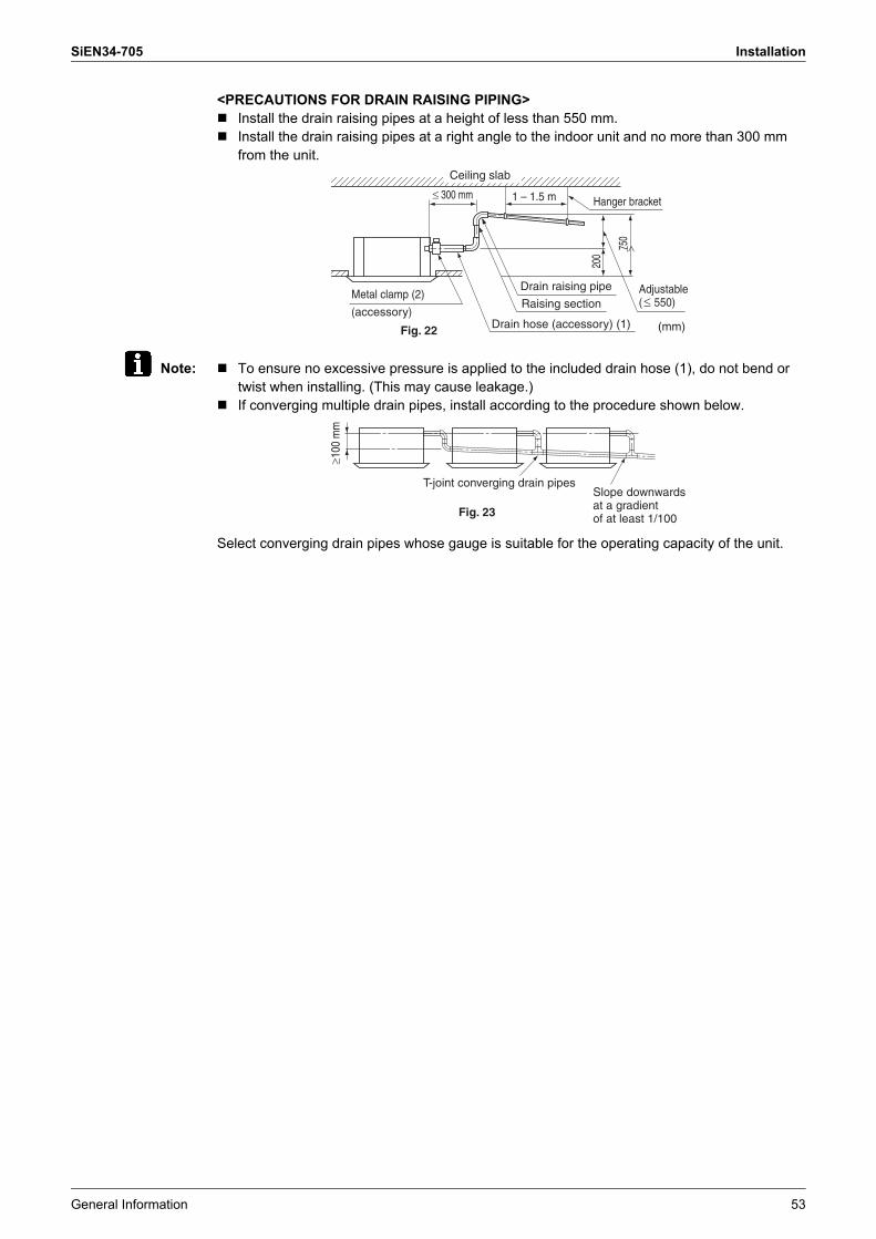
SiEN34-705 Installation
General Information 53
<PRECAUTIONS FOR DRAIN RAISING PIPING>! Install the drain raising pipes at a height of less than 550 mm.! Install the drain raising pipes at a right angle to the indoor unit and no more than 300 mm
from the unit.
Note: ! To ensure no excessive pressure is applied to the included drain hose (1), do not bend or twist when installing. (This may cause leakage.)
! If converging multiple drain pipes, install according to the procedure shown below.
Select converging drain pipes whose gauge is suitable for the operating capacity of the unit.
Ceiling slab
Drain raising pipe
(mm)
750
Hanger bracket1 – 1.5 m300 mm
200
Fig. 22
≥
≥
≥Adjustable ( 550)
Metal clamp (2)
(accessory) Raising section
Drain hose (accessory) (1)≥1
00 m
m
Fig. 23
Slope downwards at a gradient of at least 1/100
T-joint converging drain pipes
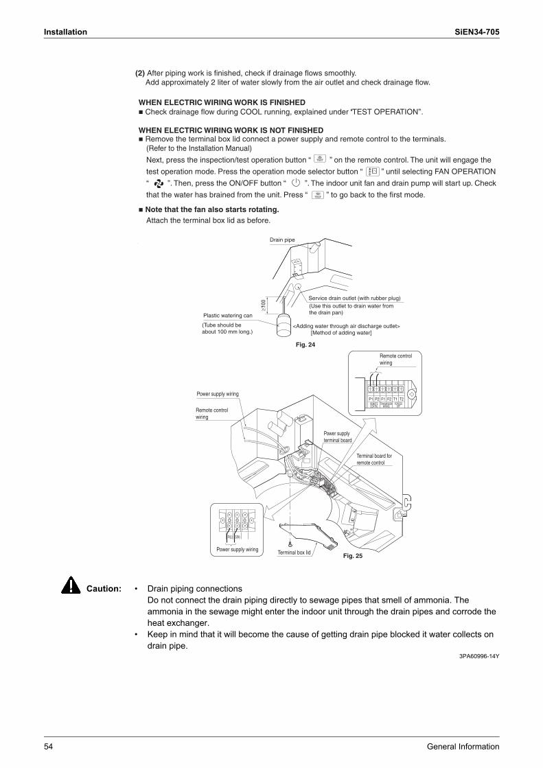
Installation SiEN34-705
54 General Information
Caution: � Drain piping connectionsDo not connect the drain piping directly to sewage pipes that smell of ammonia. The ammonia in the sewage might enter the indoor unit through the drain pipes and corrode the heat exchanger.
� Keep in mind that it will become the cause of getting drain pipe blocked it water collects on drain pipe.
3PA60996-14Y
TEST
WHEN ELECTRIC WIRING WORK IS FINISHED � Check drainage flow during COOL running, explained under ‘‘TEST OPERATION’’.
WHEN ELECTRIC WIRING WORK IS NOT FINISHED � Remove the terminal box lid connect a power supply and remote control to the terminals.
(Refer to the Installation Manual)
Next, press the inspection/test operation button “ ” on the remote control. The unit will engage the
test operation mode. Press the operation mode selector button “ ” until selecting FAN OPERATION
“ ”. Then, press the ON/OFF button “ ”. The indoor unit fan and drain pump will start up. Check
that the water has brained from the unit. Press “ ” to go back to the first mode.
� Note that the fan also starts rotating. Attach the terminal box lid as before.
TEST
≥?10
0
Fig. 24
R(L) S(N)
T2T1F2F1P2P1REMOTECONTRL
TRANSMISSIONWIRING
FORCEDOFF
Fig. 25
(Tube should be about 100 mm long.)
Plastic watering can
Service drain outlet (with rubber plug)(Use this outlet to drain water from the drain pan)
<Adding water through air discharge outlet> [Method of adding water]
Drain pipe
Remote control wiring
Remote control wiring
Power supply wiring
Power supply terminal board
Terminal board for remote control
Power supply wiring Terminal box lid
(2) After piping work is finished, check if drainage flows smoothly. Add approximately 2 liter of water slowly from the air outlet and check drainage flow.

SiEN34-705 Installation
General Information 55
Ceiling Mounted Cassette Corner Type (FXKQ-MA)
Drain Piping Work
(1) Carry out the drain piping.! Keep piping as short as possible and slope it
downwards so that air may not remained trapped inside the pipe.
! The diameter of the drain pipe should be greater than or equal to the diameter of the connecting pipe (vinyl tube; pipe size : 25 mm ; outer dimension : 32 mm).
! Use the drain hose and metal clamp. Insert the drain hose into the drain socket, up to the white tape. Tighten the metal clamp until the screw head is less than 4 mm from the hose.
Caution Setting the unit at an angle opposite to the drain piping might cause leaks.
! Wrap the sealing pad over the clamp and drain hose to insulate.! Insulate the drain hose inside the building.
While referring to the figure on the right, insulate the clamp and drain hose with the large sealing pad.
! If the drain hose cannot be sufficiently set on a slope, execute the drain raising piping.! Secure a downward gradient of 1 / 100 or more for the drain pipe. To accomplish this,
mount supporting brackets at an interval of 1 - 1.5 m.⟨Precautions when doing drain-up piping work.⟩ ! Make sure the drain-up piping is at most 330 mm high.! Stand the drain-up piping horizontally, and make sure it is not further than 300 mm from
the base of the drain socket.
! Use the following outline if laying concentrated drain piping.! If converging multiple drain pipes, install according to the procedure shown below.
Select converging drain pipes whose gauge is suitable for the operating capacity of the unit.
3P086156-8V
⟨⟨Rig the drain pipe as shown below and take measures against condensation. Improperly rigged piping could lead to leaks and eventually wet furniture and belongings.⟩⟩
Metal clamp
Drain hoseTape
≤4mm
Large sealing padMetal clamp(accessory) (accessory)
Ceiling slab
300 1-1.5 m
500
170
Riser
(length: mm)Metal clamp (accessory)
Drain hose (accessory)
Adjustable ( 330)
Drain-up piping
Support bracket
≥100
mm
T-joint converging drain pipes
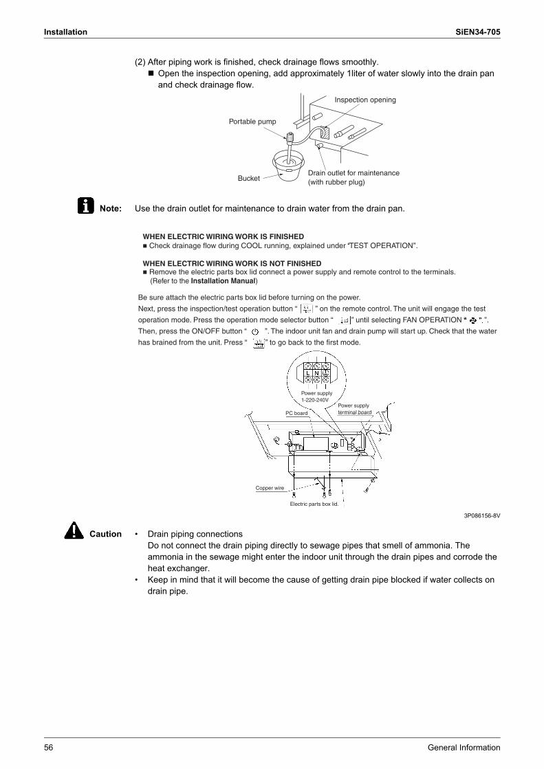
Installation SiEN34-705
56 General Information
(2) After piping work is finished, check drainage flows smoothly.! Open the inspection opening, add approximately 1liter of water slowly into the drain pan
and check drainage flow.
Note: Use the drain outlet for maintenance to drain water from the drain pan.
3P086156-8V
Caution � Drain piping connectionsDo not connect the drain piping directly to sewage pipes that smell of ammonia. The ammonia in the sewage might enter the indoor unit through the drain pipes and corrode the heat exchanger.
� Keep in mind that it will become the cause of getting drain pipe blocked if water collects on drain pipe.
Inspection opening
Drain outlet for maintenance (with rubber plug)
Portable pump
Bucket
WHEN ELECTRIC WIRING WORK IS FINISHED � Check drainage flow during COOL running, explained under ‘‘TEST OPERATION’’.
WHEN ELECTRIC WIRING WORK IS NOT FINISHED � Remove the electric parts box lid connect a power supply and remote control to the terminals.
(Refer to the Installation Manual)
Be sure attach the electric parts box lid before turning on the power.
Next, press the inspection/test operation button “ ” on the remote control. The unit will engage the test
operation mode. Press the operation mode selector button “ ” until selecting FAN OPERATION “ ”.
Then, press the ON/OFF button “ ”. The indoor unit fan and drain pump will start up. Check that the water
has brained from the unit. Press “ ” to go back to the first mode.
PC board
Power supply1-220-240V
Power supplyterminal board
Copper wire
Electric parts box lid.

SiEN34-705 Installation
General Information 57
Slim Ceiling Mounted Duct Type (FXDQ)
Drain Piping Work1. Install the drain piping.
! Make sure the drain works properly.! The diameter of the drain piping should be greater than or equal to the diameter of the
connecting pipe (vinyl tube; pipe size: 20 mm; outer dimension: 26 mm).(not including the riser)
! Keep the drain pipe short and sloping downwards at a gradient of at least 1/100 to prevent air pockets from forming. (Refer to Fig. 10)
Caution Water accumulating in the drain piping can cause the drain to clog.
! To keep the drain piping from sagging, space hanging bracket every 1 to 1.5 m.! Use the drain hose (2) and the metal clamp (1). Insert the drain hose (2) fully into the drain
pipe connection hole and firmly tighten the metal clamp (1) with the upper part of the tape on the hose end. Tighten the metal clamp (1) until the screw head is less than 4 mm from the hose. (Refer to Fig. 11, 12)
! The two areas below should be insulated because condensation may form there causing water to leak.! Drain piping passing indoors! Drain pipe connection hole
In case of PVE, NAVE (with Drain Pump) Type
In case of PVET, NVET (without Drain Pump) Type
Drain pipe connection hole
Drain pipe connection hole
Refrigerant pipes
Service drain hole (with rubber cap)
Connect the drain pipe after removing the rubber cap and insulation tubing attached to the connection hole.
Refrigerant pipes
Central drain piping(with a slope of at least 1/100)
100m
m
or m
ore
Fig. 10

Installation SiEN34-705
58 General Information
Referring the figure below, insulate the metal clamp (1) and drain hose (2) using the included large sealing pad (5). (Refer to Fig. 12)
3PN05141-4SIn case of PVE · N(A)VE (with Drain Pump) Type
<PRECAUTIONS>Drain piping connections! Do not connect the drain piping directly to sewage pipes that smell of ammonia. The
ammonia in the sewage might enter the indoor unit through the drain piping and corrode the heat exchanger.
! Do not twist or bend the drain hose (2), so that excessive force is not applied to it. (This type of treatment may cause leaking.)
! If you are using central drain piping, follow the procedure outlined in the figure 10.! Select central drain piping of proper size according to the capacity of the connected unit.
3PN05141-4S
2. After piping work is finished, check drainage flows smoothly.! Gradually insert approximately 1L of water into the drain pan to check drainage in the
manner described below.
<PRECAUTIONS FOR DRAIN RAISING PIPE>! Make sure the drain raising pipe height is no higher than 600mm.! Place the drain raising pipe vertically and make sure it is no further than 300mm from the unit.
(Refer to Fig. 13)
In case of NVET Type
! Gradually pour approximately 1L of water from the outlet hole into the drain pan to check drainage.
! Check the drainage
Metal clamp (1)
(accessory)
Fig. 11 Fig. 12
Drain hose (2)
(accessory)
Tape
Large sealing pad (5)
accessoryMetal clamp (1)
(accessory)
�4mm
300 mm or less
Metal clamp (1) (accessory)
Drain hose (2) (accessory)
Ceiling slab
Drain rising pipe
(Field supply)
Adjustable range(600mm or less)
Hanging bracket1 - 1.5m
Fig. 13
Portable pump
RefrigerantpipesBucket
Air outlet
Drain outlet
Refrigerant pipes
Drain outlet
Air outletPortable pump
Bucket
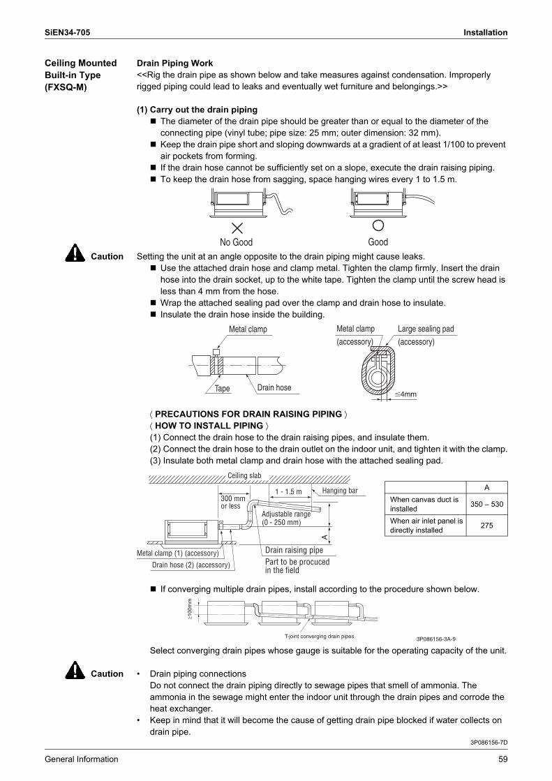
SiEN34-705 Installation
General Information 59
Ceiling Mounted Built-in Type (FXSQ-M)
Drain Piping Work<<Rig the drain pipe as shown below and take measures against condensation. Improperly rigged piping could lead to leaks and eventually wet furniture and belongings.>>
(1) Carry out the drain piping! The diameter of the drain pipe should be greater than or equal to the diameter of the
connecting pipe (vinyl tube; pipe size: 25 mm; outer dimension: 32 mm).! Keep the drain pipe short and sloping downwards at a gradient of at least 1/100 to prevent
air pockets from forming.! If the drain hose cannot be sufficiently set on a slope, execute the drain raising piping.! To keep the drain hose from sagging, space hanging wires every 1 to 1.5 m.
Caution Setting the unit at an angle opposite to the drain piping might cause leaks.! Use the attached drain hose and clamp metal. Tighten the clamp firmly. Insert the drain
hose into the drain socket, up to the white tape. Tighten the clamp until the screw head is less than 4 mm from the hose.
! Wrap the attached sealing pad over the clamp and drain hose to insulate.! Insulate the drain hose inside the building.
⟨ PRECAUTIONS FOR DRAIN RAISING PIPING ⟩⟨ HOW TO INSTALL PIPING ⟩(1) Connect the drain hose to the drain raising pipes, and insulate them.(2) Connect the drain hose to the drain outlet on the indoor unit, and tighten it with the clamp.(3) Insulate both metal clamp and drain hose with the attached sealing pad.
! If converging multiple drain pipes, install according to the procedure shown below.
Select converging drain pipes whose gauge is suitable for the operating capacity of the unit.
Caution � Drain piping connectionsDo not connect the drain piping directly to sewage pipes that smell of ammonia. The ammonia in the sewage might enter the indoor unit through the drain pipes and corrode the heat exchanger.
� Keep in mind that it will become the cause of getting drain pipe blocked if water collects on drain pipe.
3P086156-7D
No Good Good
AWhen canvas duct is installed 350 � 530
When air inlet panel is directly installed 275
Tape Drain hose
Metal clamp
�4mm
Metal clamp
(accessory)
Large sealing pad
(accessory)
A
300 mm or less
Metal clamp (1) (accessory)
Drain hose (2) (accessory)
Ceiling slab
Part to be procuced in the field
Adjustable range(0 - 250 mm)
Hanging bar1 - 1.5 m
Drain raising pipe
≥100
mm
3P086156-3A-9T-joint converging drain pipes

Installation SiEN34-705
60 General Information
(2) After piping work is finished, check drainage flows smoothly.! Open the water inlet lid, add approximately
1 liter of water gradually and check drainage flow.
[ WHEN ELECTRIC WIRING WORK IS FINISHED ]! Check drainage flow during COOL running, explained under �TEST OPERATION�.[ WHEN ELECTRIC WIRING WORK IS NOT FINISHED ]! Remove the electric parts box lid, connect a
power supply and remote control to the terminals.(Refer to the �HOW TO CONNECT WIRINGS�)Be sure attach the electric parts box lid before turning on the power.Next, press the inspection/ test operation button � � on the remote control. The unit will engage the test operation mode.Press the operation mode selector button � � until selecting FAN OPERATION � � . Then, press the ON/OFF button � �. The indoor unit fan and drain pump will start up. Check that the water has drained from the unit. Press � � to go back to the first mode.
! You can check whether drainage is satisfactory or not by removing the access opening lid and checking the water level of the drain pan through the access opening.
! Be careful when doing so because the fan is turning at the same time.3P086156-7D
Water inlet
Portable pump
Water inlet lid
Refrigerant pipes
Bucket
Drain outlet for maintenance
(with rubber plug)
Note: Use this outlet to drain water from the drain pan.
«Adding water from inspection opening»
Open
Close
L N
X Y
NL
Power supplyterminal block
220V – 240V single phase power supply.
Indoor PC board
Electric parts boxTEST
TEST

SiEN34-705 Installation
General Information 61
Ceiling Mounted Duct Type (FXMQ-MA)
Drain Piping Work⟨⟨Rig the drain pipe as shown below and take measures against condensation. Improperly rigged piping could lead to leaks and eventually wet furniture and belongings.⟩⟩⟨⟨Insulate the drain hose inside the building.⟩⟩
(1) Carry out the drain piping.
! Keep piping as short as possible and slope it downwards so that air may not remained trapped inside the pipe.
! Keep pipe size equal to or greater than that of the connecting pipe (Vinyl pipe of 25 mm nominal diameter and 32 mm outer diameter).
! Use the attached drain hose and clamp.Tighten the clamp firmly.
! Insulate the clamp metal with the sealing pad.
! There is negative pressure inside the unit relative to atmospheric pressure when the unit is running, so be sure to provide drain flap on the drain outlet. (See the figure)
! In order to prevent foreign matter from building up inside the piping, you should avoid curves as much as possible, and arrange so the trap can be cleaned.
Note: ! If converging multiple drain pipes, install according to the procedure shown below. (Install a drain trap for each indoor unit.)
! A drain trap need not be installed.! The diameter of the piping is the same as that of the connecting pipe (PS1B), and should
be kept equal to or greater than that of the connecting pipe.
FXMQ40-125MAVE
50m
m o
r m
ore
50m
m o
r m
ore
Bottom of unit
Attached drain hose
Metal clamp
Drain hoseTape4mm or less
Drain hose
Large sealing pad
(accessory)Metal clamp(accessory)
FXMQ200 · 250MAVE
100m
m
or m
ore
Installation SiEN34-705
62 General Information
(2) After piping work is finished, check drainage flows smoothly.
! Add approximately 1 liter of water slowly from the air inlet and check drainage flow.
! Open the water supply port, add approximately 1 liter of water slowly into the drain pan and check drainage flow.
Caution ! Drain piping connectionsDo not connect the drain piping directly to sewage pipes that smell of ammonia. The ammonia in the sewage might enter the indoor unit through the drain pipes and corrode the heat exchanger.
C: 3P086156-6U
FXMQ40-125MAVE
FXMQ200 · 250MAVE

SiEN34-705 Installation
General Information 63
Ceiling Suspended Type (FXHQ-MA)
3PN01417-7P
Fig. 20
Rear side (metal plate) removable part
Rear left-facing drain piping
Left dressing board removable part
Left-facing drain piping
Drain Piping WorkRig the drain pipe as shown below and take measures against condensation. Improperly rigged piping could lead to leaks and eventually wet furniture and belongings.
(1) Carry out the drain piping.� For drain work, rig the pipes so that they drain reliably.� The drain pipe outlet direction can be chosen from the right rear, right, left rear, and left. Refer to
“REFRIGERANT PIPING WORK” for right rear and right direction, and refer to Fig. 20 for left rear and left direction.
� For left drain pipe outlet, remove the rubber plug and the insulation on the drain pipe connecting opening on the left side of the unit and change the position to the right side.
� Insert the rubber stopper securely, all the way to the base, in order to prevent water leakage.� The diameter of the drain pipe should be greater than or equal to the diameter of the connecting pipe.
(Vinyl tube; pipe size: 20 mm; outer dimension: 26 mm)� Keep the drain pipe short and sloping downwards at a gradient of at least 1/100 to prevent air pockets
from forming. (Refer to Fig. 21)� Use the attached drain hose (1) and clamp (2).
Insert the drain hose into the drain socket, up to the gray tape.(Refer to Fig. 22) Tighten the clamp until the screw head is less than 4 mm from the hose. (Refer to Fig. 23)(Be careful of the installation direction. Install so that the clamp metal does not contact the intake grill.)
� Wrap the attached sealing pad (8) over the clamp and drain hose to insulate. (Refer to Fig. 23)� No folding of drain hose inside the indoor unit. (Refer to Fig. 24)
(If there is slack in the drain hose, it may cause damage to the intake grill.)
Tilt downDo not lift
(When drain hose is connected)Good Wrong
Fig. 21
Make sure it is not in the water
Make sure there is no slack
Taping area
Metal clamp (2) (accessory)
Fig. 22
Drain hose (1) (accessory)
Sealing pad (8) (accessory)
≤4
≤4
(length : mm)
< Facing rear right or right > < Facing rear left or left >Fig. 23
Metal clamp (2) (accessory)
Metal clamp (2) (accessory)
Sealing pad (8) (accessory)

Installation SiEN34-705
64 General Information
Notes: ! To ensure no excessive pressure is applied to the included drain hose (1), do not bend or twist when installing. (This may cause leakage.)
! If converging multiple drain pipes, install according to the procedure shown below.
Select converging drain pipes whose gauge is suitable for the operating capacity of the unit.
(2) Confirm that smooth drainage is achieved after the piping work.! Add 0.6 liter of water in the drain pan from the air outlet for confirming drainage.
(Refer to Fig. 25)
Caution ! Drain piping connectionsDo not connect the drain piping directly to sewage pipes that smell of ammonia. The ammonia in the sewage might enter the indoor unit through the drain pipes and corrode the heat exchanger.
! Keep in mind that it will become the cause of getting drain pipe blocked if water collects on drain pipe.
≥100
mm
T-joint converging drain pipes
Slope downwards at a gradient of at least 1/100
Wrong
Fig. 24
Fig. 25
Portable pump
Air outlet
Bucket
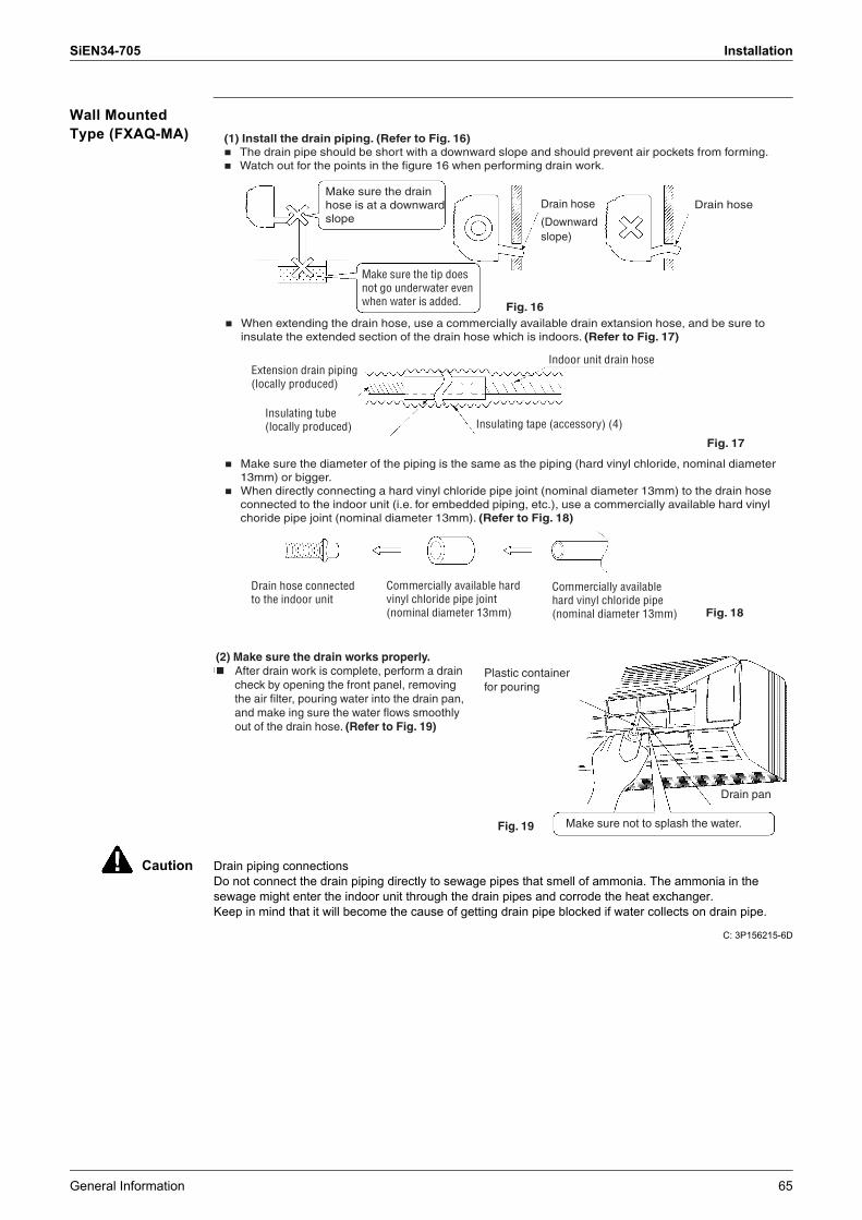
SiEN34-705 Installation
General Information 65
Wall Mounted Type (FXAQ-MA)
Caution Drain piping connectionsDo not connect the drain piping directly to sewage pipes that smell of ammonia. The ammonia in the sewage might enter the indoor unit through the drain pipes and corrode the heat exchanger.Keep in mind that it will become the cause of getting drain pipe blocked if water collects on drain pipe.
C: 3P156215-6D
(1) Install the drain piping. (Refer to Fig. 16)� The drain pipe should be short with a downward slope and should prevent air pockets from forming.� Watch out for the points in the figure 16 when performing drain work.
� When extending the drain hose, use a commercially available drain extansion hose, and be sure to insulate the extended section of the drain hose which is indoors. (Refer to Fig. 17)
� Make sure the diameter of the piping is the same as the piping (hard vinyl chloride, nominal diameter 13mm) or bigger.
� When directly connecting a hard vinyl chloride pipe joint (nominal diameter 13mm) to the drain hose connected to the indoor unit (i.e. for embedded piping, etc.), use a commercially available hard vinyl choride pipe joint (nominal diameter 13mm). (Refer to Fig. 18)
Make sure the drain hose is at a downward slope
Make sure the tip does not go underwater even when water is added.
Drain hose
(Downwardslope)
Drain hose
Extension drain piping (locally produced)
Insulating tube (locally produced)
Indoor unit drain hose
Insulating tape (accessory) (4)
Drain hose connected to the indoor unit
Commercially available hard vinyl chloride pipe joint (nominal diameter 13mm)
Commercially available hard vinyl chloride pipe (nominal diameter 13mm)
Fig. 16
Fig. 17
Fig. 18
(2) Make sure the drain works properly.� After drain work is complete, perform a drain
check by opening the front panel, removing the air filter, pouring water into the drain pan, and make ing sure the water flows smoothly out of the drain hose. (Refer to Fig. 19)
Plastic container for pouring
Drain pan
Make sure not to splash the water.Fig. 19

Installation SiEN34-705
66 General Information
Floor Standing/Concealed Floor Standing Type (FXLQ-MA, FXNQ-MA)
Drain Piping Work<<Rig the drain pipe as shown below and take measures against condensation. Improperly rigged piping could lead to leaks and eventually wet furniture and belongings.>>(1) Carry out the drain piping.
Connect the drain hose (1) using the attached hose and parts, as shown in the right drawing.
� If converging multiple drain pipes, install according to the procedure shown below.
Select converging drain pipes whose gauge is suitable for the operating capacity of the unit.(2) After piping work is finished, check drainage flows smoothly.
� Add approximately 1 liter of water slowly from the air outlet and check drainage flow.(3) Be sure to insulate all indoor pipes.
Caution ! Drain piping connectionsDo not connect the drain piping directly to sewage pipes that smell of ammonia. The ammonia in the sewage might enter the indoor unit through the drain pipes and corrode the heat exchanger.
! Keep in mind that it will become the cause of getting drain pipe blocked if water collects on drain pipe.
C: 3P086154-2K
3/4 B drain pipe
50 or more
Drip pan
Cut to suitable length
(length : mm)
Piping process inside unit
Tilt
Metal clamp (accessory) (2)
Drain hose (accessory) (1)
Slope downwards at a gradient of at least 1/100
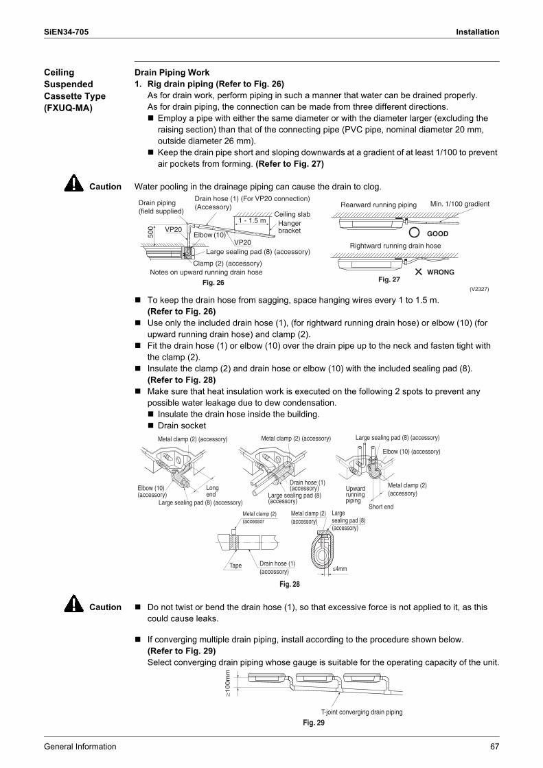
SiEN34-705 Installation
General Information 67
Ceiling Suspended Cassette Type (FXUQ-MA)
Drain Piping Work1. Rig drain piping (Refer to Fig. 26)
As for drain work, perform piping in such a manner that water can be drained properly.As for drain piping, the connection can be made from three different directions.! Employ a pipe with either the same diameter or with the diameter larger (excluding the
raising section) than that of the connecting pipe (PVC pipe, nominal diameter 20 mm, outside diameter 26 mm).
! Keep the drain pipe short and sloping downwards at a gradient of at least 1/100 to prevent air pockets from forming. (Refer to Fig. 27)
Caution Water pooling in the drainage piping can cause the drain to clog.
! To keep the drain hose from sagging, space hanging wires every 1 to 1.5 m.(Refer to Fig. 26)
! Use only the included drain hose (1), (for rightward running drain hose) or elbow (10) (for upward running drain hose) and clamp (2).
! Fit the drain hose (1) or elbow (10) over the drain pipe up to the neck and fasten tight with the clamp (2).
! Insulate the clamp (2) and drain hose or elbow (10) with the included sealing pad (8).(Refer to Fig. 28)
! Make sure that heat insulation work is executed on the following 2 spots to prevent any possible water leakage due to dew condensation.! Insulate the drain hose inside the building.! Drain socket
Caution ! Do not twist or bend the drain hose (1), so that excessive force is not applied to it, as this could cause leaks.
! If converging multiple drain piping, install according to the procedure shown below.(Refer to Fig. 29)Select converging drain piping whose gauge is suitable for the operating capacity of the unit.
1 - 1.5 m
VP20
VP20
500
Elbow (10)
Drain piping (field supplied)
Drain hose (1) (For VP20 connection) (Accessory)
Ceiling slabHanger bracket
Large sealing pad (8) (accessory)
Clamp (2) (accessory)Notes on upward running drain hose
Fig. 26
Rearward running piping Min. 1/100 gradient
Rightward running drain hose
GOOD
WRONGFig. 27
(V2327)
Fig. 28
Short end
Long end
Metal clamp (2) (accessory)Metal clamp (2) (accessory) Large sealing pad (8) (accessory)
Elbow (10) (accessory)
Drain hose (1) (accessory)
Large sealing pad (8) (accessory)
Upward running piping
Metal clamp (2)(accessory)
Elbow (10) (accessory)
Large sealing pad (8) (accessory)
Large sealing pad (8) (accessory)
Metal clamp (2) (accessor
Metal clamp (2) (accessory)
Tape Drain hose (1) (accessory) ≤4mm
≥1
00
mm
T-joint converging drain piping
Fig. 29
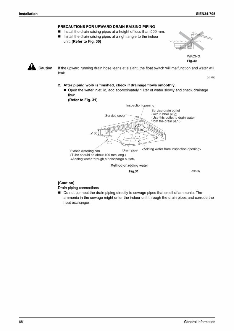
Installation SiEN34-705
68 General Information
PRECAUTIONS FOR UPWARD DRAIN RAISING PIPING! Install the drain raising pipes at a height of less than 500 mm.! Install the drain raising pipes at a right angle to the indoor
unit. (Refer to Fig. 30)
Caution If the upward running drain hose leans at a slant, the float switch will malfunction and water will leak.
(V2328)
2. After piping work is finished, check if drainage flows smoothly.! Open the water inlet lid, add approximately 1 liter of water slowly and check drainage
flow.(Refer to Fig. 31)
[Caution]Drain piping connections! Do not connect the drain piping directly to sewage pipes that smell of ammonia. The
ammonia in the sewage might enter the indoor unit through the drain pipes and corrode the heat exchanger.
WRONGFig.30
(V2329)
Service cover
Plastic watering can (Tube should be about 100 mm long.)<Adding water through air discharge outlet>
Method of adding water
Fig.31
Drain pipe <Adding water from inspection opening>
Service drain outlet (with rubber plug). (Use this outlet to drain water from the drain pan.)
Inspection opening
>100>100

SiEN34-705 Installation
General Information 69
Caution ! Electrical wiring work should be done by a certified electrician.! If someone who does not have the proper qualifications performs the work, perform the
following after the test run is complete.
! Remove the control box lid and change the emergency switch above the PC board assembly of the indoor unit from �NORM.� to �EMERG.�. Connect the single-phase power supply (1, 3) and ground wire to the inter-unit wiring (50Hz 220-240V) terminal block and confirm drain operation.Be sure to change the switch before turning on the power. (Refer to Fig. 32)
Caution ! Clamp solidly to clamp C to tension is not added to the wiring connections. ! Be aware that the fan will turn during the operation.
! After confirming drainage, turn off the power and be sure to change the emergency switch back to �NORM.�.
(V2330)
1 2 3
Inter-unit wiring terminal block
Inter-unit wiring terminal block
Single phase power supplyClamp CEmergency switch
• Checking the drain
• After the checking
Indoor PC board assembly
Fig. 32
Clamp C
Tab
NORM. EMERG
NORM. EMERG

Installation SiEN34-705
70 General Information
Outdoor Air Processing Unit (FXMQ-MF)
Drain Piping Work<<Rig the drain pipe as shown below and take measures against condensate. Improperly rigged piping could lead to leaks and eventually wet furniture and belongings.>><<Insulate the drain pipes inside the building and the drain sockets.>>
1. Carry out the drain piping.! The drain pipe should be short with a downward slope lower than 1/100 and should prevent
air pockets from forming.! The diameter of the pipe is the same as that of the connecting pipe (PS1B), and should be
kept equal to or greater than that of the connecting pipe.Note:! If converging multiple drain pipes, install according to the procedure shown below. (Select
an appropriate central drain pipe thickness for the units they will be connected to.)
2. After piping work is finished, check drainage flow smoothly.! Open the water supply port, add approximately 1 liter of water slowly into the drain pan and
check drainage flow. (Refer to Fig. 13)Pools of drainage can cause the drain pipes to clog.
Caution Do not connect the drain pipe directly to sewage pipes that smell of ammonia. The ammonia in the sewage might enter the unit through the drain pipes and corrode the heat exchanger.
Fig. 12
(Install with a downward slope of at least 1/100)
Central drain pipe10
0 m
m
or m
ore
Fig. 13
Water supply port
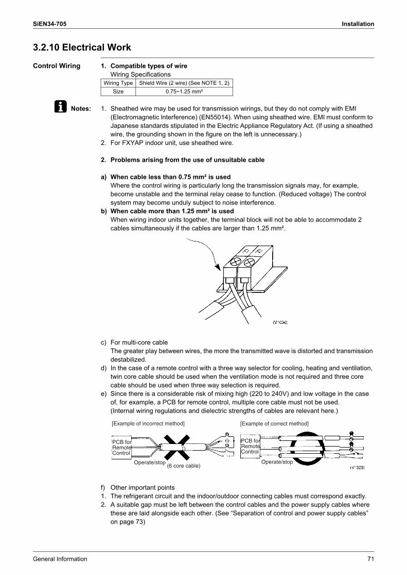
SiEN34-705 Installation
General Information 71
3.2.10 Electrical Work
Control Wiring 1. Compatible types of wireWiring Specifications
Notes: 1. Sheathed wire may be used for transmission wirings, but they do not comply with EMI (Electromagnetic lnterference) (EN55014). When using sheathed wire. EMI must conform to Japanese standards stipulated in the Electric Appliance Regulatory Act. (If using a sheathed wire, the grounding shown in the figure on the left is unnecessary.)
2. For FXYAP indoor unit, use sheathed wire.
2. Problems arising from the use of unsuitable cable
a) When cable less than 0.75 mm² is usedWhere the control wiring is particularly long the transmission signals may, for example, become unstable and the terminal relay cease to function. (Reduced voltage) The control system may become unduly subject to noise interference.
b) When cable more than 1.25 mm² is usedWhen wiring indoor units together, the terminal block will not be able to accommodate 2 cables simultaneously if the cables are larger than 1.25 mm².
c) For multi-core cableThe greater play between wires, the more the transmitted wave is distorted and transmission destabilized.
d) In the case of a remote control with a three way selector for cooling, heating and ventilation, twin core cable should be used when the ventilation mode is not required and three core cable should be used when three way selection is required.
e) Since there is a considerable risk of mixing high (220 to 240V) and low voltage in the case of, for example, a PCB for remote control, multiple core cable must not be used. (Internal wiring regulations and dielectric strengths of cables are relevant here.)
f) Other important points1. The refrigerant circuit and the indoor/outdoor connecting cables must correspond exactly.2. A suitable gap must be left between the control cables and the power supply cables where
these are laid alongside each other. (See �Separation of control and power supply cables� on page 73)
Wiring Type Shield Wire (2 wire) (See NOTE 1, 2)Size 0.75~1.25 mm²
[Example of incorrect method] [Example of correct method]
Operate/stop(6 core cable)
PCB for Remote Control
PCB for Remote Control
Operate/stop
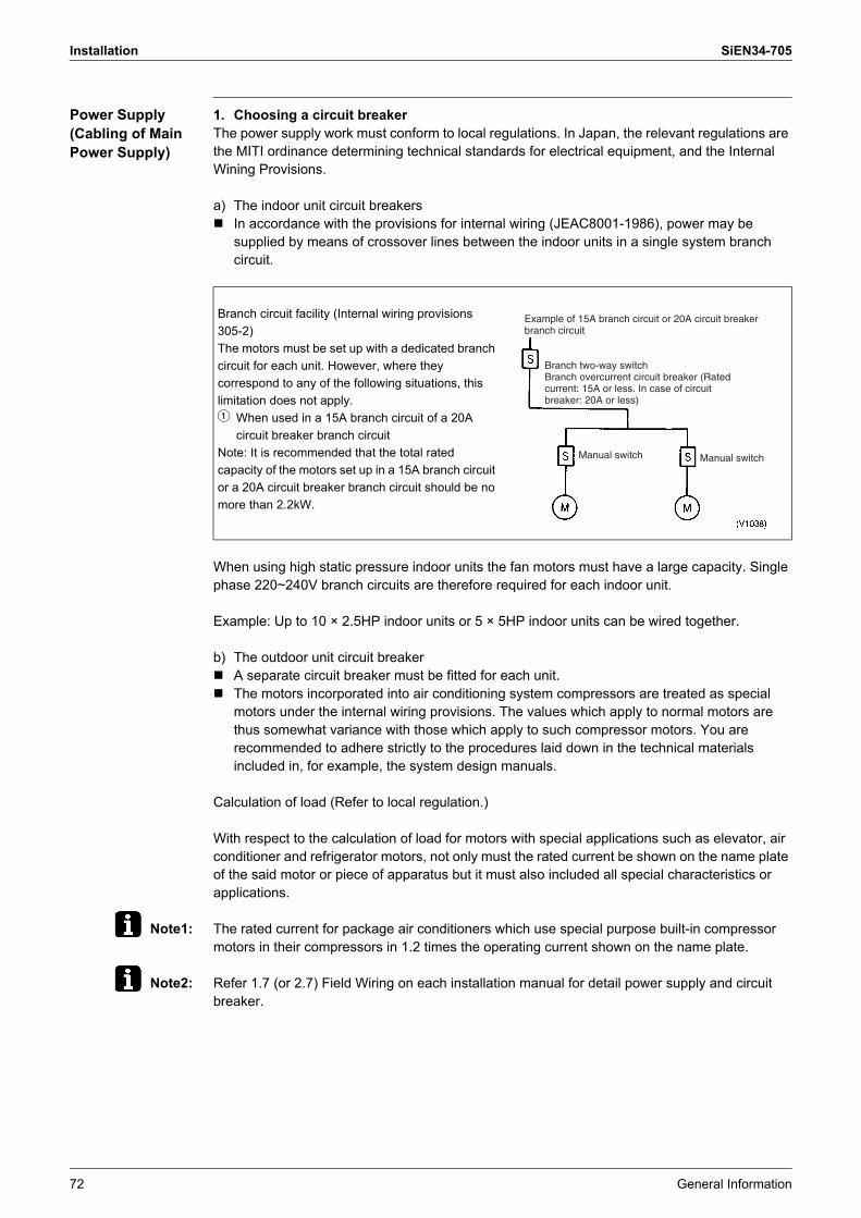
Installation SiEN34-705
72 General Information
Power Supply (Cabling of Main Power Supply)
1. Choosing a circuit breakerThe power supply work must conform to local regulations. In Japan, the relevant regulations are the MITI ordinance determining technical standards for electrical equipment, and the Internal Wining Provisions.
a) The indoor unit circuit breakers! In accordance with the provisions for internal wiring (JEAC8001-1986), power may be
supplied by means of crossover lines between the indoor units in a single system branch circuit.
When using high static pressure indoor units the fan motors must have a large capacity. Single phase 220~240V branch circuits are therefore required for each indoor unit.
Example: Up to 10 × 2.5HP indoor units or 5 × 5HP indoor units can be wired together.
b) The outdoor unit circuit breaker! A separate circuit breaker must be fitted for each unit.! The motors incorporated into air conditioning system compressors are treated as special
motors under the internal wiring provisions. The values which apply to normal motors are thus somewhat variance with those which apply to such compressor motors. You are recommended to adhere strictly to the procedures laid down in the technical materials included in, for example, the system design manuals.
Calculation of load (Refer to local regulation.)
With respect to the calculation of load for motors with special applications such as elevator, air conditioner and refrigerator motors, not only must the rated current be shown on the name plate of the said motor or piece of apparatus but it must also included all special characteristics or applications.
Note1: The rated current for package air conditioners which use special purpose built-in compressor motors in their compressors in 1.2 times the operating current shown on the name plate.
Note2: Refer 1.7 (or 2.7) Field Wiring on each installation manual for detail power supply and circuit breaker.
Branch circuit facility (Internal wiring provisions 305-2)The motors must be set up with a dedicated branch circuit for each unit. However, where they correspond to any of the following situations, this limitation does not apply.1 When used in a 15A branch circuit of a 20A
circuit breaker branch circuitNote: It is recommended that the total rated capacity of the motors set up in a 15A branch circuit or a 20A circuit breaker branch circuit should be no more than 2.2kW.
Example of 15A branch circuit or 20A circuit breaker branch circuit
Branch two-way switchBranch overcurrent circuit breaker (Rated current: 15A or less. In case of circuit breaker: 20A or less)
Manual switchManual switch
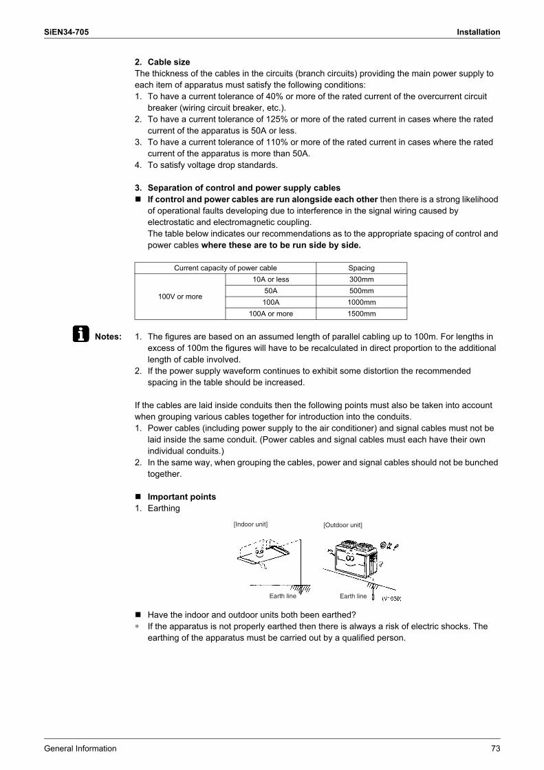
SiEN34-705 Installation
General Information 73
2. Cable sizeThe thickness of the cables in the circuits (branch circuits) providing the main power supply to each item of apparatus must satisfy the following conditions:1. To have a current tolerance of 40% or more of the rated current of the overcurrent circuit
breaker (wiring circuit breaker, etc.).2. To have a current tolerance of 125% or more of the rated current in cases where the rated
current of the apparatus is 50A or less.3. To have a current tolerance of 110% or more of the rated current in cases where the rated
current of the apparatus is more than 50A.4. To satisfy voltage drop standards.
3. Separation of control and power supply cables! If control and power cables are run alongside each other then there is a strong likelihood
of operational faults developing due to interference in the signal wiring caused by electrostatic and electromagnetic coupling.The table below indicates our recommendations as to the appropriate spacing of control and power cables where these are to be run side by side.
Notes: 1. The figures are based on an assumed length of parallel cabling up to 100m. For lengths in excess of 100m the figures will have to be recalculated in direct proportion to the additional length of cable involved.
2. If the power supply waveform continues to exhibit some distortion the recommended spacing in the table should be increased.
If the cables are laid inside conduits then the following points must also be taken into account when grouping various cables together for introduction into the conduits.1. Power cables (including power supply to the air conditioner) and signal cables must not be
laid inside the same conduit. (Power cables and signal cables must each have their own individual conduits.)
2. In the same way, when grouping the cables, power and signal cables should not be bunched together.
! Important points1. Earthing
! Have the indoor and outdoor units both been earthed?∗ If the apparatus is not properly earthed then there is always a risk of electric shocks. The
earthing of the apparatus must be carried out by a qualified person.
Current capacity of power cable Spacing
100V or more
10A or less 300mm50A 500mm
100A 1000mm100A or more 1500mm
[Indoor unit] [Outdoor unit]
Earth line Earth line
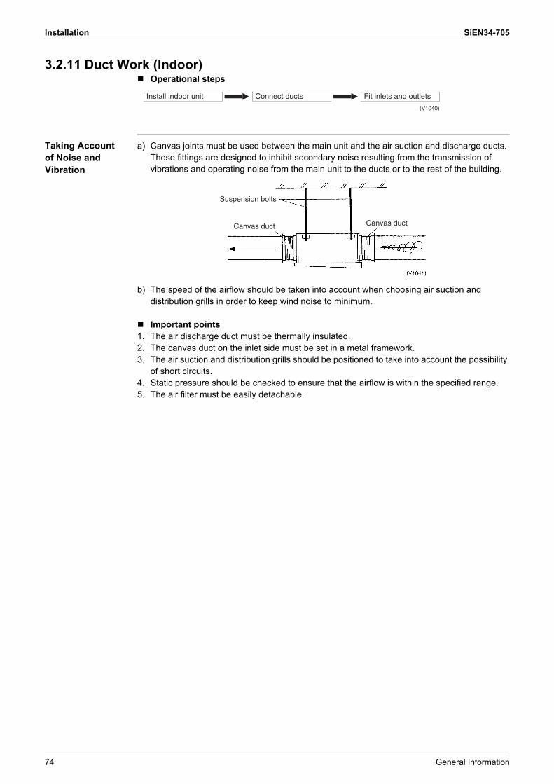
Installation SiEN34-705
74 General Information
3.2.11 Duct Work (Indoor)! Operational steps
Taking Account of Noise and Vibration
a) Canvas joints must be used between the main unit and the air suction and discharge ducts. These fittings are designed to inhibit secondary noise resulting from the transmission of vibrations and operating noise from the main unit to the ducts or to the rest of the building.
b) The speed of the airflow should be taken into account when choosing air suction and distribution grills in order to keep wind noise to minimum.
! Important points1. The air discharge duct must be thermally insulated.2. The canvas duct on the inlet side must be set in a metal framework.3. The air suction and distribution grills should be positioned to take into account the possibility
of short circuits.4. Static pressure should be checked to ensure that the airflow is within the specified range.5. The air filter must be easily detachable.
Install indoor unit Connect ducts Fit inlets and outlets
(V1040)
Suspension bolts
Canvas duct Canvas duct

SiEN34-705 Installation
General Information 75
3.2.12 Selection of LocationThis unit, both indoor and outdoor, is suitable for installation in a commercial and light industrial environment. If installed as a household appliance it could cause electromagnetic interference.The VRV outdoor units should be installed in a location that meets the following requirements:1. The foundation is strong enough to support the weight of the unit and the floor is flat to
prevent vibration and noise generation.2. The space around the unit is adequate for servicing and the minimum space for air inlet and
air outlet is available. (Refer to below figure and choose one of both possibilities.)3. There is no danger of fire due to leakage of inflammable gas.4. Ensure that water cannot cause any damage to the location in case it drips out the unit (e.g.
in case of a blocked drain pipe).5. The piping length between the outdoor unit and the indoor unit may not exceed the allowable
piping length. (See �Example of connection�.)6. Select the location of the unit in such a way that neither the discharged air nor the sound
generated by the unit disturb anyone.7. Make sure that the air inlet and outlet of the unit are not positioned towards the main wind
direction. Frontal wind will disturb the operation of the unit. If necessary, use a windscreen to block the wind.
Caution 1. An inverter air conditioner may cause electronic noise generated from AM broadcasting. Examine where to install the main air conditioner and electric wires, keeping proper distances away from stereo equipment, personal computers, etc.
If the electric wave of AM broadcasting is particularly weak, keep distances of 3m or more and use conduit tubes for power and transmission lines.
2. In heavy snowfall areas, select an installation site where snow will not affect operation of the unit.
3. If condensate may drip on downstairs (walkway) depending on the floor condition, take a measure such as the installation of central drain pan kit (sold separately).
4. The refrigerant R-410A itself is nontoxic, nonflammable and is safe. If the refrigerant should leak however, its concentration may exceed the allowable limit depending on room size. Due to this it could be necessary to take measures against leakage. Refer to the chapter �Caution for refrigerant leaks�.
≥10 ≥10≥10
≥20 ≥20
≥10
≥50≥50
≥50
≥200 ≥400 ≥400
≥50
≥10
≥300 ≥300
≥300
≥500 ≥500
≥500≥500
≥100 ≥100
≥100≥100
≥300
< If installed as a single unit >(Pattern 1)
(Pattern 2)
(Pattern 3)
(Pattern 1)
(Pattern 2)
(Pattern 3)
< When installed in serial >
Front side
Front side
Front side
Front side
Front side
Front side
No limit to wall heightNo limit to wall height
Service space of suction side
Service space of front side
Service space of suction side
Service space of front side
Service space of suction side
Service space of front side
Service space of front side
Service space of suction side
1500
500
h1
h2
Fron
t sid
e
Suc
tion
side
B
A
h1 = A (Actual height) – 1500h2 = B (Actual height) – 500
If this height is exceeded, calculate h1 and h2 shown in the figure below, and add the service space for the front and suction sides to h1/2 and h2/2.
For Patterns 1 and 2 in figure :• Wall height for front side no higher than
1500 mm.• Wall height on the suction side no higher
than 500 mm.• Wall height for sides – no limit.
≥1500
(mm)
≥1000
≥100
0≥100
0
≥150
0
≥1500
≥1500
indoor unit
Branch switch, overcurrent breaker
personal computer or radio
remote control
COOL / HEAT selector
Branch switch, overcurrent breaker
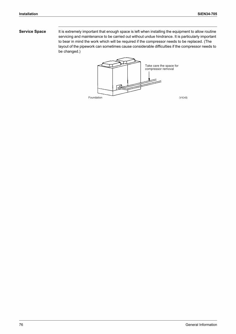
Installation SiEN34-705
76 General Information
Service Space It is extremely important that enough space is left when installing the equipment to allow routine servicing and maintenance to be carried out without undue hindrance. It is particularly important to bear in mind the work which will be required if the compressor needs to be replaced. (The layout of the pipework can sometimes cause considerable difficulties if the compressor needs to be changed.)
Take care the space for compressor removal
Foundation

SiEN34-705 Installation
General Information 77
3.2.13 Inspecting and Handling the Unit• At delivery, the package should be checked and any damage should be reported
immediately to the carrier claims agent.• When handling the unit, take into account the following:1. Fragile, handle the unit with care.
Keep the unit upright in order to avoid compressor damage.2. Decide on the transportation route.3. If a forklift is to be used, pass the forklift arms through the large openings on the bottom of
the unit.
4. If hanging the unit, use a cloth sling to prevent damaging the unit when hanging it. Keeping the following points in mind, hang the unit following the procedure shown in figure 6.
• Use a sling sufficiently strong to hold the mass of the unit.• Use 2 belts of at least 8m long.• Place extra cloth or boards in the locations where the casing comes in contact with the sling
to prevent damage. • Hoist the unit making sure it is being lifted at its center of gravity.5. After installation, remove the transportation clasp attached to the large openings.
Notes: • Use belt sling of 20mm width or less which adequately bears the weight of the product. • Apply a filler cloth on a fork to prevent coating of the bottom frame from coming off and rust
from occurring when bringing in the unit with anti-corrosion treatment type using a forklift.
Transportation clasp (yellow)
Fixed screws of transportation clasp
Hole (large)
Fork
For 5HP type, carry the belt sling through the hole (large)
Belt sling Belt sling
Hole (large)
Hole (small)
Board
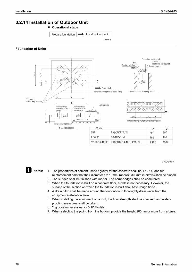
Installation SiEN34-705
78 General Information
3.2.14 Installation of Outdoor Unit! Operational steps
Foundation of Units
Notes: 1. The proportions of cement : sand : gravel for the concrete shall be 1 : 2 : 4, and ten reinforcement bars that their diameter are 10mm, (approx. 300mm intervals) shall be placed.
2. The surface shall be finished with mortar. The corner edges shall be chamfered.3. When the foundation is built on a concrete floor, rubble is not necessary. However, the
surface of the section on which the foundation is built shall have rough finish.4. A drain ditch shall be made around the foundation to thoroughly drain water from the
equipment installation area.5. When installing the equipment on a roof, the floor strength shall be checked, and water-
proofing measures shall be taken.6. Y groove unnecessary for 5HP Models.7. When selecting the piping from the bottom, provide the height 200mm or more from a base.
(V1150)
Install outdoor unitPrepare foundation
C:3D040102P
Y grooveExcept 5Hp Modeles
When building a foundation on the ground
When building a foundation on the concrete floor
groove groove
X - X cross section
Drain ditch(Smooth down grade of about 1/50)
Drain ditch
NutSpring washer
Frame
Foundation bolt type: JA Size M12 Four bolts are required
3 thread ridges
Foundation bolt executing method
When installing multiple units in connectionFloor
Model5HP
8.10HP
12�14�16�18HP
RX(Y)Q5PY1, YL
Q8�10PY1, YL
RX(Y)Q12�14�16�18PY1, YL
497
792
1 102
697
992
1302
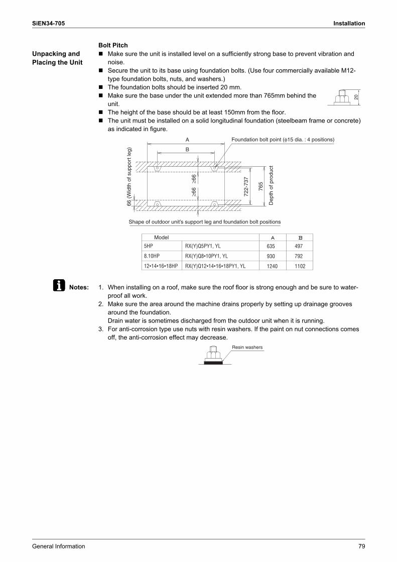
SiEN34-705 Installation
General Information 79
Bolt PitchUnpacking and Placing the Unit
! Make sure the unit is installed level on a sufficiently strong base to prevent vibration and noise.
! Secure the unit to its base using foundation bolts. (Use four commercially available M12-type foundation bolts, nuts, and washers.)
! The foundation bolts should be inserted 20 mm.! Make sure the base under the unit extended more than 765mm behind the
unit.! The height of the base should be at least 150mm from the floor.! The unit must be installed on a solid longitudinal foundation (steelbeam frame or concrete)
as indicated in figure.
Notes: 1. When installing on a roof, make sure the roof floor is strong enough and be sure to water-proof all work.
2. Make sure the area around the machine drains properly by setting up drainage grooves around the foundation.Drain water is sometimes discharged from the outdoor unit when it is running.
3. For anti-corrosion type use nuts with resin washers. If the paint on nut connections comes off, the anti-corrosion effect may decrease.
20
722-
737
≥66
≥66 76
5
A
B
66 (
Wid
th o
f sup
port
leg)
Foundation bolt point (φ15 dia. : 4 positions)
Shape of outdoor unit’s support leg and foundation bolt positions
Dep
th o
f pro
duct
Model
5HP
8.10HP
12•14•16•18HP
RX(Y)Q5PY1, YL
RX(Y)Q8•10PY1, YL
RX(Y)Q12•14•16•18PY1, YL
635
930
1240
497
792
1102
Resin washers
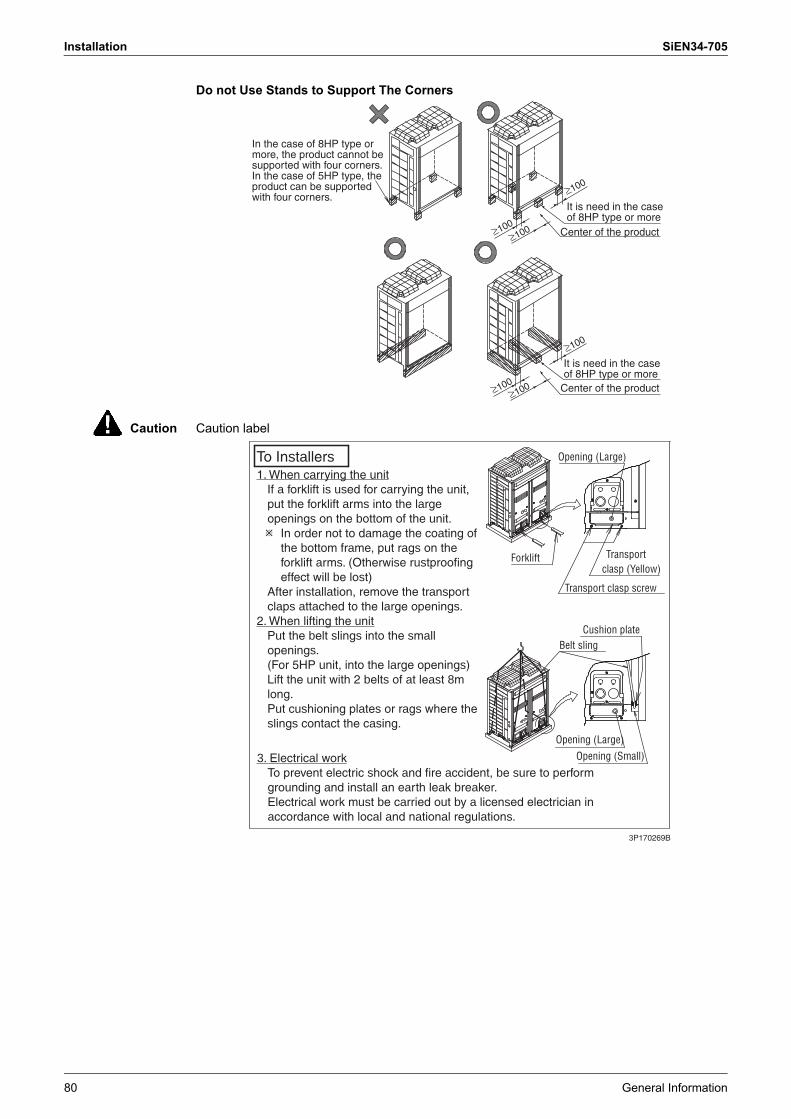
Installation SiEN34-705
80 General Information
Do not Use Stands to Support The Corners
Caution Caution label
In the case of 8HP type or more, the product cannot be supported with four corners.In the case of 5HP type, the product can be supported with four corners.
It is need in the case of 8HP type or more
Center of the product
It is need in the case of 8HP type or more
Center of the product
≥100
≥100
≥100
≥100
≥100
≥100
3P170269B
1. When carrying the unit� If a forklift is used for carrying the unit,
put the forklift arms into the large openings on the bottom of the unit.! In order not to damage the coating of
the bottom frame, put rags on the forklift arms. (Otherwise rustproofing effect will be lost)
� After installation, remove the transport claps attached to the large openings.
2. When lifting the unit� Put the belt slings into the small
openings.(For 5HP unit, into the large openings)
� Lift the unit with 2 belts of at least 8m long.
� Put cushioning plates or rags where the slings contact the casing.
3. Electrical work� To prevent electric shock and fire accident, be sure to perform
grounding and install an earth leak breaker.� Electrical work must be carried out by a licensed electrician in
accordance with local and national regulations.
To Installers Opening (Large)
Forklift
Transport clasp screw
Cushion plateBelt sling
Opening (Large)Opening (Small)
Transport clasp (Yellow)

SiEN34-705 Installation
General Information 81
3P170269B
Check the system status on LED(H2P) on the Pc board (A1P) from inspection door on the EL, COMPO, BOX coverLED display shows:TURNING OFF***Normal TURNING ON***Abnormal FLASHING***Under preparation(For multi system, check the PC board of the master unit. The master unit is the outdoor unit connected to the transmission wiring to the indoor units.)
To Service Person
● Beware the fan running when inspect.● Do not touch the charged parts when inspect
To ALL handlers● For removing the front panel, lift the panel a little (①), and pull
the panel towards you (➁).● For the location of the EL, COMPO. BOX and the service port,
see as shown below on the right.
Hanging lug
Front panel
EL. COMPO. BOX
Wiring diagram
(On the back side of the cover)
Inspection door
Earth terminal(Inside the EL. COMPO. BOX)
Gas shutoff valve service port
(Cooling-low pressureHeating-high pressure)
Liquid shutoff valve service port
(Cooling-high pressureHeating-intermediate
pressure)
Refrigerant charging port
(Heating-low pressure)
WARNING Caution to electric shock
.
3P173367B
● Do not remove the cover by force. If the cover is deformed, water may enter inside, wich may cause failure.
● Install the cover so that the sealing material labeled on the lower part on its back side may not get caught in the EL. COMPO. BOX inside. (See as shown below)
CAUTION for removing and installing the EL. COMPO. BOX cover
Method of removal CAUTION
Method of installationWARNING Caution to electric shock
➀ Remove the 4 screws fixing the cover.➁ Pull the cover downward till its top shows.➂ Pull the cover frontward and remove it.
For installing the cover, follow the procedures in the reverse order.
Shut off the power supply before removing the cover. If your fingers thouch the electrical components it may cause electric shock.
It cause damp or water to enter
Power supply terminal block
EL. COMPO. BOX cover
Front side
Sealing material Sealing material
Do not draw the lower part of the cover
Top cover
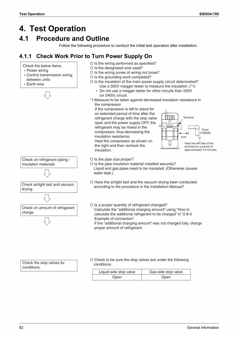
Test Operation SiEN34-705
82 General Information
4. Test Operation4.1 Procedure and Outline
Follow the following procedure to conduct the initial test operation after installation.
4.1.1 Check Work Prior to Turn Power Supply On
Terminal
Dryer(1000W)
Check airtight test and vacuum drying.
Check on refrigerant piping / insulation materials
Check on amount of refrigerant charge
Check the stop valves for conditions.
Check the below items.2Power wiring2Control transmission wiring
between units2Earth wire
� Is the wiring performed as specified?� Is the designated wire used?� Is the wiring screw of wiring not loose?� Is the grounding work completed?� Is the insulation of the main power supply circuit deteriorated?
Use a 500V megger tester to measure the insulation. (*1)2 Do not use a megger tester for other circuits than 200V (or 240V) circuit.
*1:Measure to be taken against decreased insulation resistance in the compressorIf the compressor is left to stand for an extended period of time after the refrigerant charge with the stop valve open and the power supply OFF, the refrigerant may be mixed in the compressor, thus decreasing the insulation resistance.Heat the compressor as shown on the right and then recheck the insulation.
� Is the pipe size proper?� Is the pipe insulation material installed securely?
Liquid and gas pipes need to be insulated. (Otherwise causes water leak.)
� Have the airtight test and the vacuum drying been conducted according to the procedure in the Installation Manual?
� Is a proper quantity of refrigerant changed?Calculate the “additional charging amount” using “How to calculate the additional refrigerant to be charged” in “2-6-5 Example of connection”.If the “additional charging amount” was not charged fully, charge proper amount of refrigerant.
� Check to be sure the stop valves are under the following conditions.
Liquid-side stop valveOpen
Gas-side stop valveOpen
Terminal
Dryer (1000W)
Heat the left side of the terminal for a period of approximately 15 minutes.
5cm

SiEN34-705 Test Operation
General Information 83
4.1.2 Turn Power On� Be sure to turn the power on 6 hours before starting operation to protect
compressors. (to power on clankcase heater)
� Check to be sure the transmission is normal.The transmission is normal if the LEDs display conditions as shown in table below.
(*) The master unit is the outdoor unit to which the transmission wiring for the indoor units is conncted. The other outdoor units are slave units.
� Make field settings if needed.(For the setting procedure, refer to information in "4.4.2. Field Setting from Outdoor Unit" on page 101 onward.)For the outdoor-multi system, make field settings with the master unit. (Field settings made with the slave unit will be all invalid.)
The check operations shown below will be automatically initiated.• Check for erroneous wirings• Check for failure to open stop valves• Check for excessive refrigerant refilling• Automatic judgment of piping length
� Before starting the normal operation after the completion of check operations, make sure indoor and outdoor units normally operate.
Turn outdoor unit and indoor unit power on.
Check the LED display of the outdoor unit PC board.
Conduct check operations.
Check for normal operation.
Make field settings with outdoor unit PC board.
LED display(Default status before
delivery)
Micro-computer
operation monitor
MODE
HAP
9
9
9
9
H1P
7
7
7
7
H2P
7
7
7
7
H3P
7
7
7
7
H4P
7
7
7
7
H5P
7
7
7
7
H6P
7
7
7
7
H7P
7
7
7
7
H8P
7
7
9
7
Master
Slave 1
Slave 2
One outdoor unit installed
When multiple outdoor unit installed (*)
TESTIND
COOL / HEAT selectLED display 7 ON 7 7 OFF 9 9 Blinking
MASTER SLAVE
Low noise Demand Multi

Test Operation SiEN34-705
84 General Information
4.1.3 Check Operation[Check Operation Procedure]STEP1 Make the onsite setting as needed using the dip switches on the outdoor unit PC-board
(A1P) with the power off (See below instruction Note1)STEP2 Close the EL. COMPO. BOX lid and all front panels except as the side of the EL.
COMPO. BOX and turn on the power to the outdoor unit and all connected indoor units.(Be sure to turn the power on at least 6 hours before operation in order to have powerrunning to the crank case heater.)
STEP3 Check the LED display on the outdoor unit PC-board (A1P) is as shown in the tablebelow and transmission is normal.
LED display: 3...OFF, 4...ON, 5...Blinking
(*)How to distinguish the master unit, sub unit 1, and sub unit 2 in the multi system.
STEP4 Make the onsite settings as needed using the push button (BS1-BS5) on the outdoor unit PC-board (A1P) with the power on. (See �4.4.2 Field Setting from Outdoor Unit.�)
STEP5 Perform the check operation following the Check Operation Method of the [Service Precautions] label on the EL. COMPO. BOX lid. The system operation for about 40 minutes and automatically stops the check operation.If the malfunction code is not displayed in the remote control after the system stop, check operation is completed. Normal operation will be possible after 5 minutes. If the malfunction code is displayed in the remote control, correct the malfunction following [remote control displays malfunction code] and perform the check operation again.
Note1: Onsite Settings with the Power OffIf the COOL/HEAT selector was connected to the outdoor unit set the dip switch (DS1) on the outdoor unit PC-board (A1P) to �ON� (it is set to �OFF� when shipped from the factory).For the position of the dip switch (DS1), see the �Service Precautions� label (see at right) which is attached to the EL. COMPO. BOX lid.
LED display(Default status of shipped)
SERV. MONI-TOR
MODE TEST/HWL
C/H SELECTORL.N.O.P DEMA-
ND MULTIIND MASTE
R SLAVE
HAP H1P H2P H3P H4P H5P H6P H7P H8P
Single system 5 3 3 4 3 3 3 3 3
Multi system
(*)
Master unit 5 3 3 4 3 3 3 3 4
Sub unit 1 5 3 3 3 3 3 3 3 5
Sub unit 2 5 3 3 3 3 3 3 3 3
Method 1: By the H8P (MULTI) LED display
4 (ON): Master unit 5 (Blinking): Sub unit 1 3 (OFF): Sub unit 2Method 2: By the transmission wiring to indoor unit
Transmission wiring is connected: Master unit
Transmission wiring is not connected : Sub unit 1 or Sub unit 2
Inspection door
[Service Precautions] label
EL.COMPO. BOX lid

SiEN34-705 Test Operation
General Information 85
[remote control displays malfunction code]
If any malfunction codes other than the above are displayed, check the service manual for how to respond.
Malfunction code Installation error Remedial action
E3, E4F3, F6UF
The shutoff valve of the outdoor unit is left closed. Open the shutoff valve.
U1 The phases of the power to the outdoor unit is reversed.
Exchange two of the three phases (L1, L2, L3) to make a proper connection.
U1U4LC
No power is supplied to an outdoor or indoor unit (including phase interruption).
Make sure the power source wire is properly connected to the outdoor unit and revise if necessary.
UFThere is conflict on the connection of transmission wiring in the system.
Check if the refrigerant piping line and the transmission wiring are consistent with each other.
E3F6UF
Refrigerant overcharge.Recalculate the additional amount refrigerant from the piping length and correct the refrigerant charge level by recovering any excessive refrigerant with a refrigerant recovery machine.
E4F3 Insufficient refrigerant.
� Check if the additional refrigerant charge has been finished correctly.
� Recalculate the additional amount refrigerant from the piping length and add the adequate amount.
U7, U4UF, UH
If the outdoor unit terminal is connected when there is one outdoor unit installed.
Remove the line from the outdoor multi terminals (Q1 and Q2).
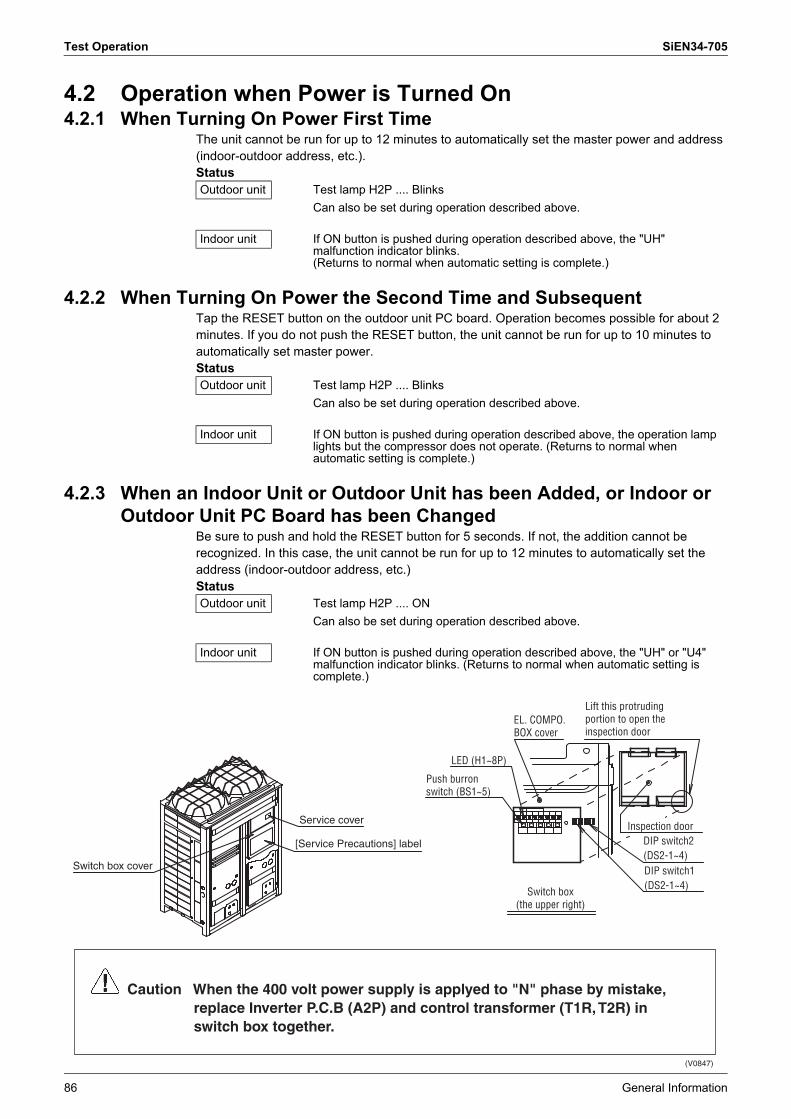
Test Operation SiEN34-705
86 General Information
4.2 Operation when Power is Turned On4.2.1 When Turning On Power First Time
The unit cannot be run for up to 12 minutes to automatically set the master power and address (indoor-outdoor address, etc.).Status
4.2.2 When Turning On Power the Second Time and SubsequentTap the RESET button on the outdoor unit PC board. Operation becomes possible for about 2 minutes. If you do not push the RESET button, the unit cannot be run for up to 10 minutes to automatically set master power.Status
4.2.3 When an Indoor Unit or Outdoor Unit has been Added, or Indoor or Outdoor Unit PC Board has been Changed
Be sure to push and hold the RESET button for 5 seconds. If not, the addition cannot be recognized. In this case, the unit cannot be run for up to 12 minutes to automatically set the address (indoor-outdoor address, etc.)Status
Outdoor unit Test lamp H2P .... BlinksCan also be set during operation described above.
Indoor unit If ON button is pushed during operation described above, the "UH" malfunction indicator blinks.(Returns to normal when automatic setting is complete.)
Outdoor unit Test lamp H2P .... BlinksCan also be set during operation described above.
Indoor unit If ON button is pushed during operation described above, the operation lamp lights but the compressor does not operate. (Returns to normal when automatic setting is complete.)
Outdoor unit Test lamp H2P .... ONCan also be set during operation described above.
Indoor unit If ON button is pushed during operation described above, the "UH" or "U4" malfunction indicator blinks. (Returns to normal when automatic setting is complete.)
Switch box cover
Service cover
[Service Precautions] label
Switch box (the upper right)
Lift this protruding portion to open the inspection door
EL. COMPO. BOX cover
Push burron switch (BS1~5)
LED (H1~8P)
Inspection door DIP switch2 (DS2-1~4)DIP switch1 (DS2-1~4)
Caution When the 400 volt power supply is applyed to "N" phase by mistake, replace Inverter P.C.B (A2P) and control transformer (T1R, T2R) in switch box together.
(V0847)
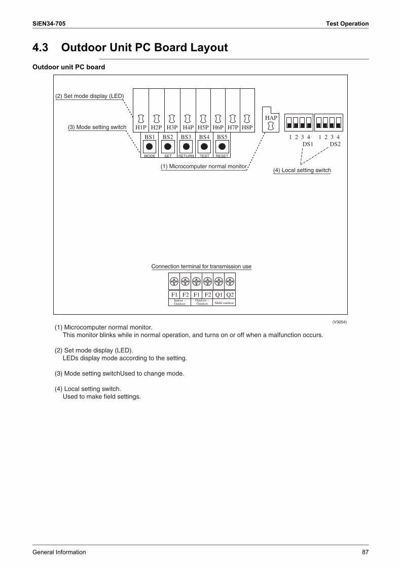
SiEN34-705 Test Operation
General Information 87
4.3 Outdoor Unit PC Board LayoutOutdoor unit PC board
BS1
MODE SET RETURN TEST RESET
BS2 BS3 BS4 BS5
H1P H2P H3P H4P H5P H6P H7P H8P
1 2 3 4 1 2 3 4
F1 F2 F1 F2 Q1 Q2
DS1 DS2
HAP
(V3054)
(1) Microcomputer normal monitor. This monitor blinks while in normal operation, and turns on or off when a malfunction occurs.
(2) Set mode display (LED).LEDs display mode according to the setting.
(3) Mode setting switchUsed to change mode.
(4) Local setting switch. Used to make field settings.
Indoor − Outdoor
Outdoor − Outdoor Multi outdoor
(2) Set mode display (LED)
(3) Mode setting switch
(1) Microcomputer normal monitor(4) Local setting switch
Connection terminal for transmission use

Test Operation SiEN34-705
88 General Information
4.4 Field Setting4.4.1 Field Setting from Remote Control
Individual function of indoor unit can be changed from the remote control. At the time of installation or after service inspection / repair, make the local setting in accordance with the following description.Wrong setting may cause malfunction.(When optional accessory is mounted on the indoor unit, setting for the indoor unit may be required to change. Refer to information in the option handbook.)
4.4.1.1 Wired Remote Control <BRC1C61, 62>
1. When in the normal mode, press the � � button for a minimum of four seconds, and the FIELD SET MODE is entered.
2. Select the desired MODE NO. with the � � button (2).3. During group control, when setting by each indoor unit (mode No. 20, 22 and 23 have been
selected), push the � � button (3) and select the INDOOR UNIT NO to be set. (This operation is unnecessary when setting by group.)
4. Push the � � upper button (4) and select FIRST CODE NO.5. Push the � � lower button (5) and select the SECOND CODE NO.6. Push the � � button (6) once and the present settings are SET.7. Push the � � button (7) to return to the NORMAL MODE.
(Example) If during group setting and the time to clean air filter is set to FILTER CONTAMINATION, HEAVY, SET MODE NO. to �10� FIRST CODE NO. to �0�, and SECOND CODE NO. to �02�.
SETTING
TEST
UNIT NO.
3 4
5671
2
UNIT NO.
.
.
MODE NO.
.
(V0292)
SECOND CODE NO.
FIRST CODE NO.
FIELD SET MODE
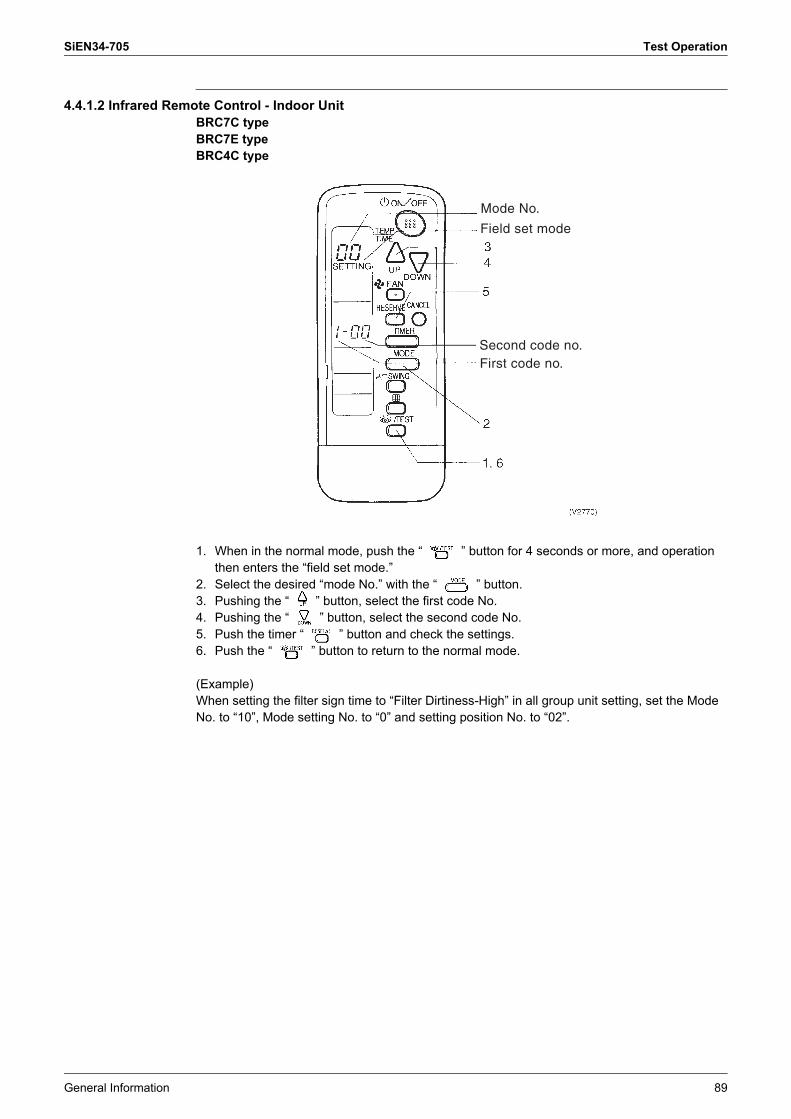
SiEN34-705 Test Operation
General Information 89
4.4.1.2 Infrared Remote Control - Indoor UnitBRC7C typeBRC7E typeBRC4C type
1. When in the normal mode, push the � � button for 4 seconds or more, and operation then enters the �field set mode.�
2. Select the desired �mode No.� with the � � button. 3. Pushing the � � button, select the first code No. 4. Pushing the � � button, select the second code No. 5. Push the timer � � button and check the settings. 6. Push the � � button to return to the normal mode.
(Example)When setting the filter sign time to �Filter Dirtiness-High� in all group unit setting, set the Mode No. to �10�, Mode setting No. to �0� and setting position No. to �02�.
Mode No.
Field set mode
Second code no.First code no.

Test Operation SiEN34-705
90 General Information
4.4.1.3 Simplified Remote ControlBRC2A51BRC2C51
1. Remove the upper part of remote control.2. When in the normal mode, press the [BS6] BUTTON (2) (field set), and the FIELD SET
MODE is entered.3. Select the desired MODE No. with the [BS2] BUTTON (3) (temperature setting s) and the
[BS3] BUTTON (3) (temperature setting t).4. During group control, when setting by each indoor unit (mode No. 20, 22, and 23 have been
selected), push the [BS8] (4) BUTTON (unit No.) and select the INDOOR UNIT NO. to be set. (This operation is unnecessary when setting by group.)
5. Push the [BS9] BUTTON (5) (set A) and select FIRST CODE NO.6. Push the [BS10] BUTTON (6) (set B) and select SECOND CODE NO.7. Push the [BS7] BUTTON (7) (set/cancel) once and the present settings are SET.8. Push the [BS6] BUTTON (8) (field set) to return to the NORMAL MODE.9. (Example) If during group setting and the time to clean air filter is set to FILTER
CONTAMINATION - HEAVY, SET MODE NO. to �10�, FIRST CODE NO. to �0�, and SECOND CODE NO. to �02�.
Mode No.
Second code no.
First code no.
Unit No.

SiEN34-705 Test Operation
General Information 91
4.4.1.4 Setting Contents and Code No. � VRV Indoor unit
Notes: 1. Settings are made simultaneously for the entire group, however, if you select the mode No. inside parentheses, you can also set by each individual unit. Setting changes however cannot be checked except in the individual mode for those in parentheses.
2. The mode numbers inside parentheses cannot be used by infrared remote controls, so they cannot be set individually. Setting changes also cannot be checked.
3. Marked are factory set.4. Do not make settings other than those described above. Nothing is displayed for functions
the indoor unit is not equipped with. 5. �88� may be displayed to indicate the remote control is resetting when returning to the
normal mode. 6. If the setting mode to �Equipped�, heat reclaim ventilation fan conducts the fan residual
operation by linking to indoor unit.
VRV system indoor unit settings
Mode No.
Note 2
Setting Switch
No.
Setting Contents Second Code No.(Note 3)01 02 03 04
10(20) 0 Filter contamination heavy/light (Setting for display time to clean air filter)(Sets display time to clean air filter to half when there is heavy filter contamination.)
Super long life filter
Light Approx. 10,000
hrs.
Heavy Approx. 5,000 hrs.
� �
Long life filter
Approx. 2,500 hrs.
Approx. 1,250 hrs.
Standardfilter
Approx. 200 hrs.
Approx. 100 hrs.
1 Long life filter type Long life filter Super long life filter
� �
2 Thermostat sensor in remote control Use No use �3 Display time to clean air filter
calculation (Set when filter sign is not to be displayed.)
Display No display �
12(22) 0 Optional accessories output selection (field selection of output for adapter for wiring)
Indoor unit turned ON by
thermostat
Operation output Malfunction output
1 ON/OFF input from outside (Set when ON/OFF is to be controlled from outside.)
Forced OFF ON/OFF control External protection device
input
�
2 Thermostat differential changeover(Set when remote sensor is to be used.)
1°C 0.5°C � �
3 OFF by thermostat fan speed LL Set fan speed � �4 Automatic mode differential (automatic
temperature differential setting for VRV system heat recovery series cool/heat)
01:0 02:1 03:2 04:3 05:4 06:5 07:6 08:7
5 Power failure automatic reset Not equipped Equipped � �13(23) 0 High air outlet velocity
(Set when installed in place with ceiling higher than 2.7 m.)
N H S �
1 Selection of air flow direction(Set when a blocking pad kit has been installed.)
F (4 directions) T (3 directions) W (2 directions) �
3 Air flow direction adjustment (Set at installation of decoration panel.)
Equipped Not equipped �
4 Field set air flow position setting Draft prevention Standard Ceiling Soiling prevention
�
5 Field set fan speed selection(fan speed control by air discharge outlet for phase control)
Standard Optional accessory 1
Optional accessory 2
�
15(25) 1 Thermostat OFF excess humidity Not equipped Equipped � �2 Direct duct connection
(when the indoor unit and heat reclaim ventilation unit are connected by duct directly.) ∗Note 6
Not equipped Equipped � �
3 Drain pump humidifier interlock selection
Not equipped Equipped � �
5 Field set selection for individual ventilation setting by remote control
Not equipped Equipped � �
6 Field set selection for individual ventilation setting by remote control
Not equipped Equipped � �
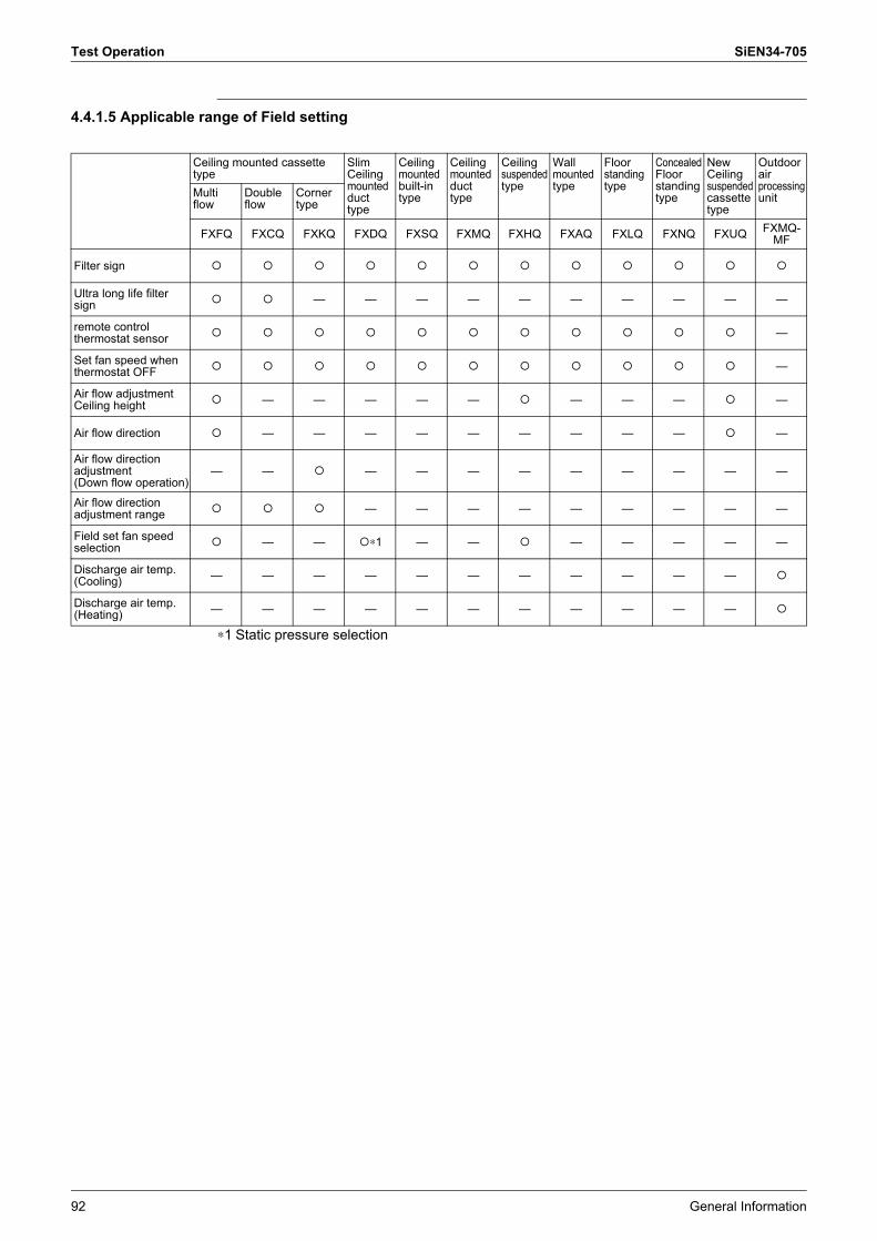
Test Operation SiEN34-705
92 General Information
4.4.1.5 Applicable range of Field setting
∗1 Static pressure selection
Ceiling mounted cassette type
Slim Ceiling mounted duct type
Ceiling mounted built-in type
Ceiling mounted duct type
Ceiling suspended type
Wall mounted type
Floor standing type
Concealed Floor standing type
New Ceiling suspended cassette type
Outdoor air processing unitMulti
flowDouble flow
Corner type
FXFQ FXCQ FXKQ FXDQ FXSQ FXMQ FXHQ FXAQ FXLQ FXNQ FXUQ FXMQ-MF
Filter sign # # # # # # # # # # # #
Ultra long life filter sign # # � � � � � � � � � �
remote control thermostat sensor # # # # # # # # # # # �
Set fan speed when thermostat OFF # # # # # # # # # # # �
Air flow adjustment Ceiling height # � � � � � # � � � # �
Air flow direction # � � � � � � � � � # �
Air flow direction adjustment (Down flow operation)
� � # � � � � � � � � �
Air flow direction adjustment range # # # � � � � � � � � �
Field set fan speed selection # � � #∗1 � � # � � � � �
Discharge air temp. (Cooling) � � � � � � � � � � � #
Discharge air temp. (Heating) � � � � � � � � � � � #
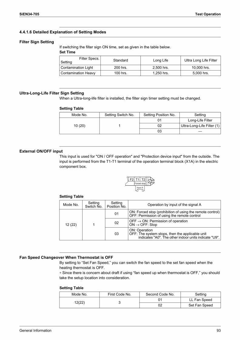
SiEN34-705 Test Operation
General Information 93
4.4.1.6 Detailed Explanation of Setting Modes
Filter Sign SettingIf switching the filter sign ON time, set as given in the table below.Set Time
Ultra-Long-Life Filter Sign SettingWhen a Ultra-long-life filter is installed, the filter sign timer setting must be changed.
Setting Table
External ON/OFF inputThis input is used for "ON / OFF operation" and "Protection device input" from the outside. The input is performed from the T1-T1 terminal of the operation terminal block (X1A) in the electric component box.
Setting Table
Fan Speed Changeover When Thermostat is OFFBy setting to �Set Fan Speed,� you can switch the fan speed to the set fan speed when the heating thermostat is OFF.∗ Since there is concern about draft if using �fan speed up when thermostat is OFF,� you should take the setup location into consideration.
Setting Table
Filter Specs.Setting Standard Long Life Ultra Long Life Filter
Contamination Light 200 hrs. 2,500 hrs. 10,000 hrs.Contamination Heavy 100 hrs. 1,250 hrs. 5,000 hrs.
Mode No. Setting Switch No. Setting Position No. Setting
10 (20) 101 Long-Life Filter02 Ultra-Long-Life Filter (1)03 �
F2 T1 T2Forced stop
Input A
Mode No. Setting Switch No.
Setting Position No. Operation by input of the signal A
12 (22) 1
01 ON: Forced stop (prohibition of using the remote control)OFF: Permission of using the remote control
02 OFF → ON: Permission of operationON → OFF: Stop
03ON: OperationOFF: The system stops, then the applicable unit
indicates "A0". The other indoor units indicate "U9".
Mode No. First Code No. Second Code No. Setting
12(22) 301 LL Fan Speed02 Set Fan Speed
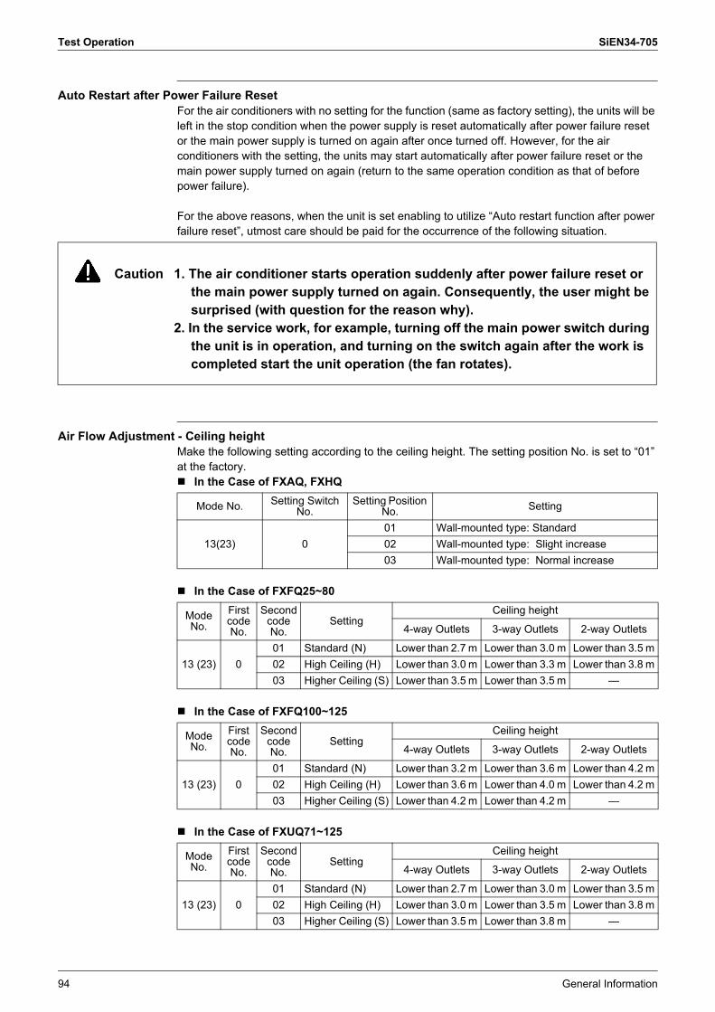
Test Operation SiEN34-705
94 General Information
Auto Restart after Power Failure ResetFor the air conditioners with no setting for the function (same as factory setting), the units will be left in the stop condition when the power supply is reset automatically after power failure reset or the main power supply is turned on again after once turned off. However, for the air conditioners with the setting, the units may start automatically after power failure reset or the main power supply turned on again (return to the same operation condition as that of before power failure).
For the above reasons, when the unit is set enabling to utilize �Auto restart function after power failure reset�, utmost care should be paid for the occurrence of the following situation.
Air Flow Adjustment - Ceiling heightMake the following setting according to the ceiling height. The setting position No. is set to �01� at the factory.! In the Case of FXAQ, FXHQ
! In the Case of FXFQ25~80
! In the Case of FXFQ100~125
! In the Case of FXUQ71~125
Caution 1. The air conditioner starts operation suddenly after power failure reset or the main power supply turned on again. Consequently, the user might be surprised (with question for the reason why).
2. In the service work, for example, turning off the main power switch during the unit is in operation, and turning on the switch again after the work is completed start the unit operation (the fan rotates).
Mode No. Setting Switch No.
Setting Position No. Setting
13(23) 001 Wall-mounted type: Standard02 Wall-mounted type: Slight increase03 Wall-mounted type: Normal increase
ModeNo.
FirstcodeNo.
Second code No.
SettingCeiling height
4-way Outlets 3-way Outlets 2-way Outlets
13 (23) 001 Standard (N) Lower than 2.7 m Lower than 3.0 m Lower than 3.5 m02 High Ceiling (H) Lower than 3.0 m Lower than 3.3 m Lower than 3.8 m03 Higher Ceiling (S) Lower than 3.5 m Lower than 3.5 m �
ModeNo.
FirstcodeNo.
Second code No.
SettingCeiling height
4-way Outlets 3-way Outlets 2-way Outlets
13 (23) 001 Standard (N) Lower than 3.2 m Lower than 3.6 m Lower than 4.2 m02 High Ceiling (H) Lower than 3.6 m Lower than 4.0 m Lower than 4.2 m03 Higher Ceiling (S) Lower than 4.2 m Lower than 4.2 m �
ModeNo.
FirstcodeNo.
Second code No.
SettingCeiling height
4-way Outlets 3-way Outlets 2-way Outlets
13 (23) 001 Standard (N) Lower than 2.7 m Lower than 3.0 m Lower than 3.5 m02 High Ceiling (H) Lower than 3.0 m Lower than 3.5 m Lower than 3.8 m03 Higher Ceiling (S) Lower than 3.5 m Lower than 3.8 m �