service manual - fisher & paykel...the step-up capacitor supplies high-voltage electricity to...
TRANSCRIPT

Domestic air conditioner
SERVICE MANUAL
Wall Mounted Type
DC Inverter FREE MATCH N-Series
AS53HE1HRA Model No. AS71NE1HRE
This service information is designed for experienced repair technicians only and is not designed for use by the general public. It does not contain warnings or cautions to advise non-technical individuals of potential dangers in attempting to service a product. Products powered by electricity should be serviced or repaired only by experienced professional technicians. Any attempt to service or Repair the product or products dealt with in this service information by anyone else could result in serious injury or death
WARNING
2016 (Qingdao Haier Air Conditioner General corp. , Ltd)All rights reserved. Unauthorized copying and distribution is a violation of law
Haier Group Version:V1 Date 2016-05-12

Table fo contents
Domestic air conditioner
Contents
1. Introduction ............................................................................................ 3
2. Features ................................................................................................ 3
3. Specifications ........................................................................................ 3
4. Sensors list ............................................................................................ 3
5. Piping diagrams ..................................................................................... 3
6. Printed Circuit Board Connector Wiring Diagram ................................. 11
7. Functions and Control .......................................................................... 16
8. System configuration ........................................................................... 27
9. Dimensional drawings ......................................................................... 42
10. Conter of gravity ................................................................................ 43
11. Service Diagnosis .............................................................................. 44
12. Circuit diagrams. ................................................................................ 59

Int oduction
Domestic air conditioner
1 Introduction
1.1 Model name explanation
A S 5 3 H E 1 H R A
Indoor unit
Type of indoor unit: S (wall-mounted)
Nominal cooling capacity (5300W)
Platform of indoor units: N (N platform)
Super-match range
Version number
Heat pump & R410A refrigerant
DC inverter
Apply toT1; 220~240V50HZ/1ph
A S 7 1 N E 1 H R E
Indoor unit
Type of indoor unit: S (wall-mounted)
Nominal cooling capacity (7100W)
Platform of indoor units: N (N platform)
Super-match range
Version number
Heat pump & R410A refrigerant
DC inverter
Apply toT1; 220~240V50HZ/1ph
Introduction
Domestic air conditioner
1.2 Safety Cautions Be sure to read the following safety cautions before conducting repair work.
The caution items are classified into “Warning” and “Caution”. The “Warning” items are especially important since they can lead to death or serious injury if they are not followed closely. The “Caution” items can also lead to serious accidents under some conditions if they are not followed. Therefore, be sure to observe all the safety caution items described below. About the pictograms
This symbol indicates an item for which caution must be exercised. The pictogram shows the item to which attention must be paid.
This symbol indicates a prohibited action. The prohibited item or action is shown inside or near the symbol. This symbol indicates an action that must be taken, or an instruction. The instruction is shown inside or near the symbol. After the repair work is complete, be sure to conduct a test operation to ensure that the equipment operates
Normally, and explain the cautions for operating the product to the customer.
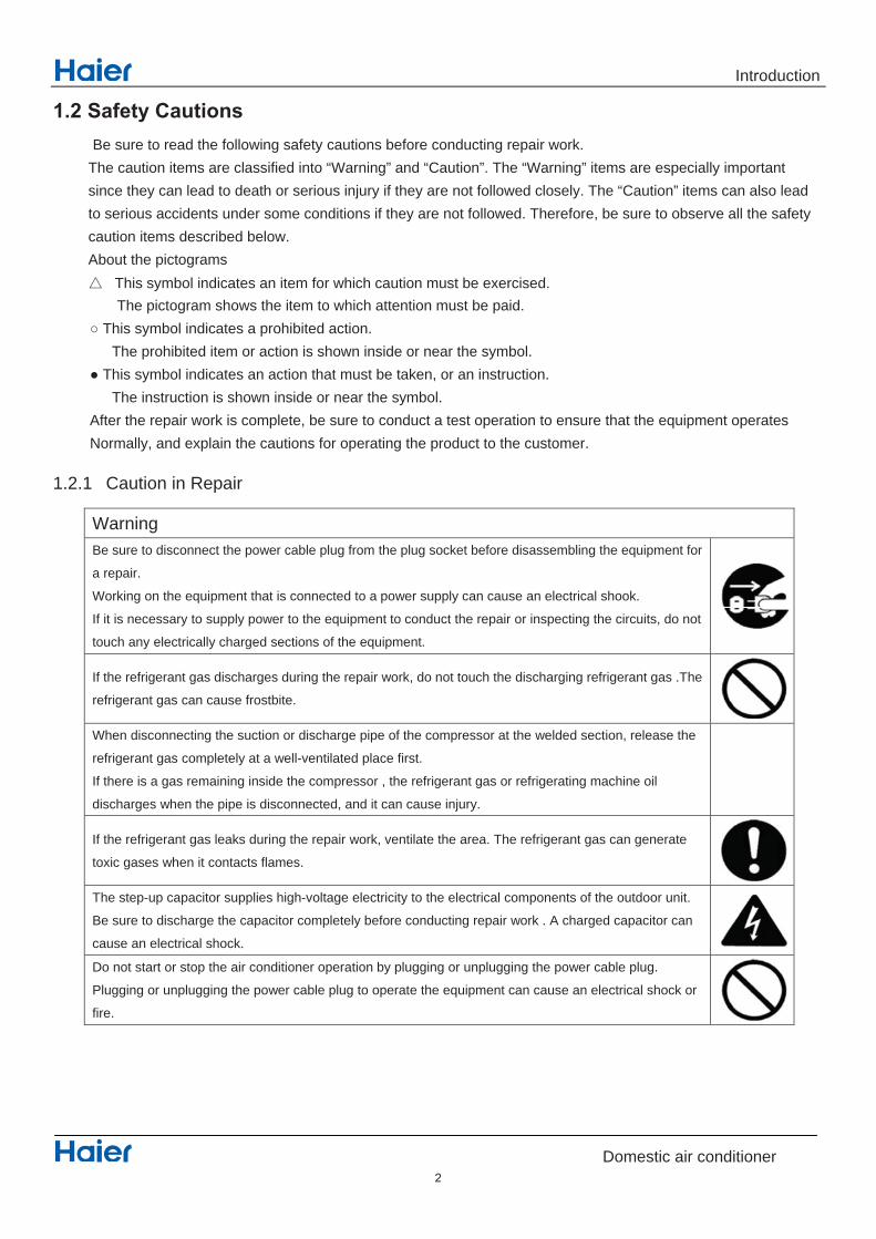
1.2.1 Caution in Repair
Warning Be sure to disconnect the power cable plug from the plug socket before disassembling the equipment for
a repair.
Working on the equipment that is connected to a power supply can cause an electrical shook.
If it is necessary to supply power to the equipment to conduct the repair or inspecting the circuits, do not
touch any electrically charged sections of the equipment.
If the refrigerant gas discharges during the repair work, do not touch the discharging refrigerant gas .The
refrigerant gas can cause frostbite.
When disconnecting the suction or discharge pipe of the compressor at the welded section, release the
refrigerant gas completely at a well-ventilated place first.
If there is a gas remaining inside the compressor , the refrigerant gas or refrigerating machine oil
discharges when the pipe is disconnected, and it can cause injury.
If the refrigerant gas leaks during the repair work, ventilate the area. The refrigerant gas can generate
toxic gases when it contacts flames.
The step-up capacitor supplies high-voltage electricity to the electrical components of the outdoor unit.
Be sure to discharge the capacitor completely before conducting repair work . A charged capacitor can
cause an electrical shock. Do not start or stop the air conditioner operation by plugging or unplugging the power cable plug.
Plugging or unplugging the power cable plug to operate the equipment can cause an electrical shock or
fire.
2

Introduction
Domestic air conditioner
Warning
Do not repair the electrical components with wet hands . Working on the equipment with wet hands can
cause an electrical shock
Do not clean the air conditioner by splashing water. Washing the unit with water can cause an electrical
shock.
Be sure to provide the grounding when repairing the equipment in a humid or wet place, to avoid
electrical
shock.
Be sure to turn off the power switch and unplug the power cable when cleaning the equipment. The
internal fan rotates at a high speed, and cause injury.
Do not tilt the unit when removing it. The water inside the unit can spill and wet the furniture and floor.
Be sure to check that the refrigerating cycle section has cooled down sufficiently before conducting
repair
work. Working on the unit when the refrigerating cycle section is hot can cause burns.
Use the welder in a well-ventilated place. Using the welder in an enclosed room can cause oxygen
deficiency.
1.2.2 Cautions Regarding Products after Repair
Warning
Be sure to use parts listed in the service parts list of the applicable model and appropriate tools to
conduct repair work. Never attempt to modify the equipment. The use of inappropriate parts or tools can
cause an electrical shock, excessive heat generation or fire.
When relocating the equipment, make sure that the new installation site has sufficient strength to
withstand the weight of the equipment.
If the installation site does not have sufficient strength and if the installation work is not conducted
securely, the equipment can fall and cause injury.
Be sure to install the product correctly by using the provided standard installation frame.
Incorrect use of the installation frame and improper installation can cause the equipment to fall, resulting
in injury.
For
integral
units only
Be sure to install the product securely in the installation frame mounted on a window frame.
If the unit is not securely mounted, it can fall and cause injury.
For
integral
units only
3

Introduction
Domestic air conditioner
Warning
Be sure to use an exclusive power circuit for the equipment, and follow the technical standards related to
the electrical equipment, the internal wiring regulations and the instruction manual for installation when
conducting electrical work.
Insufficient power circuit capacity and improper electrical work can cause an electrical shock or fire.
Be sure to use the specified cable to connect between the indoor and outdoor units. Make the
connections securely and route the cable properly so that there is no force pulling the cable at the
connection terminals.
Improper connections can cause excessive heat generation or fire.
When connecting the cable between the indoor and outdoor units, make sure that the terminal cover
does
not lift off or dismount because of the cable.
If the cover is not mounted properly, the terminal connection section can cause an electrical shock,
excessive heat generation or fire.
Do not damage or modify the power cable.
Damaged or modified power cable can cause an electrical shock or fire. Placing heavy items on the
power cable, and heating or pulling the power cable can damage the cable.
Do not mix air or gas other than the specified refrigerant (R-410A / R22) in the refrigerant system.
If air enters the refrigerating system, an excessively high pressure results, causing equipment damage
and injury.
If the refrigerant gas leaks, be sure to locate the leak and repair it before charging the refrigerant. After
charging refrigerant, make sure that there is no refrigerant leak.
If the leak cannot be located and the repair work must be stopped, be sure to perform pump-down and
close the service valve, to prevent the refrigerant gas from leaking into the room. The refrigerant gas
itself
is harmless, but it can generate toxic gases when it contacts flames, such as fan and other heaters,
stoves and ranges.
.
When replacing the coin battery in the remote controller, be sure to disposed of the old battery to prevent
children from swallowing it.
If a child swallows the coin battery, see a doctor immediately.
4
Introduction
Domestic air conditioner
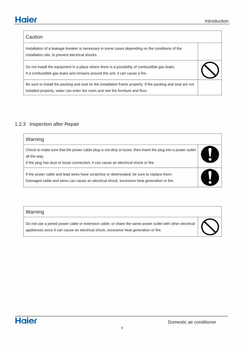
Caution
Installation of a leakage breaker is necessary in some cases depending on the conditions of the
installation site, to prevent electrical shocks.
Do not install the equipment in a place where there is a possibility of combustible gas leaks.
If a combustible gas leaks and remains around the unit, it can cause a fire.
Be sure to install the packing and seal on the installation frame properly. If the packing and seal are not
installed properly, water can enter the room and wet the furniture and floor.
1.2.3 Inspection after Repair
Warning
Check to make sure that the power cable plug is not dirty or loose, then insert the plug into a power outlet
all the way.
If the plug has dust or loose connection, it can cause an electrical shock or fire.
If the power cable and lead wires have scratches or deteriorated, be sure to replace them.
Damaged cable and wires can cause an electrical shock, excessive heat generation or fire.
Warning
Do not use a joined power cable or extension cable, or share the same power outlet with other electrical
appliances since it can cause an electrical shock, excessive heat generation or fire.
5

Introduction
Domestic air conditioner
Caution Check to see if the parts and wires are mounted and connected properly, and if the connections at the
soldered or crimped terminals are secure. Improper installation and connections can cause excessive
heat generation, fire or an electrical shock.
If the installation platform or frame has corroded, replace it. Corroded installation platform or frame can
cause the unit to fall, resulting in injury.
Check the grounding, and repair it if the equipment is not properly grounded. Improper grounding can
cause an electrical shock.
Be sure to measure the insulation resistance after the repair, and make sure that the resistance is 1 M
ohm or higher.
Faulty insulation can cause an electrical shock.
Be sure to check the drainage of the indoor unit after the repair.
Faulty drainage can cause the water to enter the room and wet the furniture and floor.
1.2.4 Using Icons Icons are used to attract the attention of the reader to specific information. The meaning of each icon is described in the table below: 1.2.5 Using Icons List
Icon Type of Information Description
Note Note
A “note” provides information that is not indispensable, but may
nevertheless be valuable to the reader, such as tips and tricks.
Caution Caution
A “caution” is used when there is danger that the reader, through
incorrect manipulation, may damage equipment, loose data, get
an
unexpected result or has to restart (part of) a procedure.
Warning Warning A “warning” is used when there is danger of personal injury.
Reference
A “reference” guides the reader to other places in this binder or in
this manual, where he/she will find additional information on a
specific topic.
6

Specifications
Domestic air conditioner
2.Features
4 Fan setting :Select the fan speed LO,MED,HI,AUTO
Anti-mold filter: Catches most small particles and remove unpleasant odors effectively.
Sleep mode: The setting temperature and the indoor noise can be adjusted to a more comfortable level
when you set the “sleep mode” during night sleep.
24Hour timer: Use the timer function to set on,or off,or from on to off,or from off to on
Auto restart: Automatic return to previous operation conditions after sudden power blackout
Easy clean design: The panel is easy to wash and the airflow vents can be detached easily
Child lock: Avoid the child's wrong operation on the remote controller
3D air flow: The 3D airflow is able to deliver the airflow horizontally and vertically.
Auto mode: Adjust the last fixed operation mode automatically.
Power mode: Quick cooling or heating
Soft mode: Lower noise operation condition Intelligent air: With twin-blade technology ,the airflow can be adjusted not to blow directly RCD module: RCD module can strongly degrade formaldehyde that caused by the chemical products. Super Nano-Quqa: Super Nano-Quqa can ionize water molecules into nanometer water ion, which can be easily absorbed by skin. Note: Y: Holding functions N: No functions
7

Specifications
Domestic air conditioner
3 Specifications-AS53HE1HRA
NOMINAL DISTRIBUTION SYSTEM VOLTAGE
1 / esahP
05 zH ycneuqerF
032 V egatloV
NOMINAL CAPACITY and NOMINAL INPUT
gnitaeh gnilooc
Capacity rated KW 5.0(1.5-6.0) 5.5(1.6-7.7)
Btu/h 17000(5119-20477) 18500(5460-26279)
Power Consumption(Rat 73.1 24.1 WK )de
30.4 7.3 W/W POCS/REES
1178 1221 hWK noitpmusnoc ygrene launnA
-³01*0.2 h/³m lavomeR erutsioM
TECHNICAL SPECIFICATIONS
633×342×5111 mm D*W*H snoisnemiD
814×243×6021 mm D*W*H snoisnemiD degakcaP
61 GK / thgieW
6.91 GK / thgiew ssorG
etihW / / roloC
Sound level Sound pressure(high/medium/low) dB 55/52/49
Sound power(high/medium/low) dB /

Specifications
Domestic air conditioner
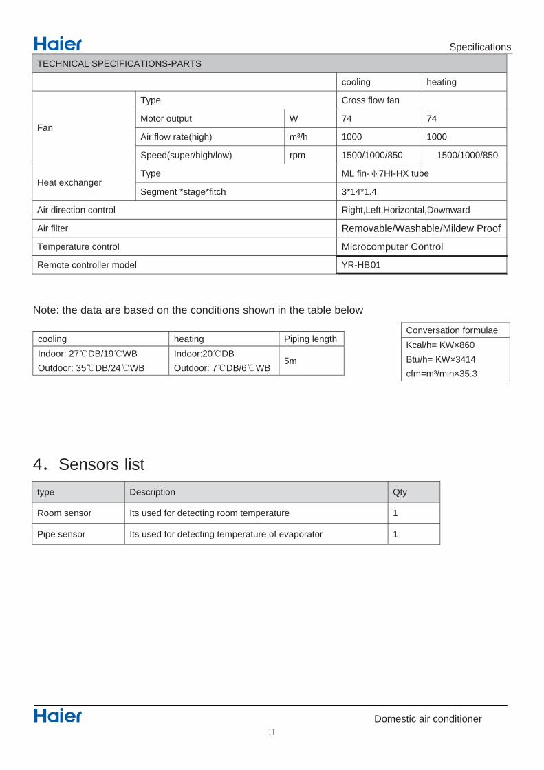
TECHNICAL SPECIFICATIONS-PARTS
cooling heating
Fan
Type Cross flow fan
Motor output W 74 74
Air flow rate(high) m³/h 1000 1000
Speed(super/high/low) rpm 950/850/750 850/775/700
Heat exchanger Type ML fin- 7HI-HX tube
Segment *stage*fitch 3*14*1.4
Air direction control Right,Left,Horizontal,Downward
Air filter Removable/Washable/Mildew Proof
Temperature control Microcomputer Control
Remote controller model YR-HB01
Note: the data are based on the conditions shown in the table below cooling heating Piping lengthIndoor: 27 DB/19 WB Outdoor: 35 DB/24 WB
Indoor:20 DB Outdoor: 7 DB/6 WB
5m
4 Sensors list type Description Qty
Room sensor Its used for detecting room temperature 1
Pipe sensor Its used for detecting temperature of evaporator 1
Conversation formulae Kcal/h= KW×860 Btu/h= KW×3414 cfm=m³/min×35.3
9

Specifications
Domestic air conditioner
3 Specifications-AS71NE1HRE
NOMINAL DISTRIBUTION SYSTEM VOLTAGE
1 / esahP
05 zH ycneuqerF
032 V egatloV
NOMINAL CAPACITY and NOMINAL INPUT
gnitaeh gnilooc
Capacity rated KW 7.3(1.9-8.4) 8.0(2.5-10.2)
Btu/h 24913(6484-28668) 27302(8532-34811)
Power Consumption(Rat 21.2 80.2 WK )de
6.3 4.3 W/W POCS/REES
1823 9871 hWK noitpmusnoc ygrene launnA
-³01*8.2 h/³m lavomeR erutsioM
TECHNICAL SPECIFICATIONS
633×342×5111 mm D*W*H snoisnemiD
814×243×6021 mm D*W*H snoisnemiD degakcaP
71 GK / thgieW
6.02 GK / thgiew ssorG
etihW / / roloC
Sound level Sound pressure(high/medium/low) dB 58/54/50
Sound power(high/medium/low) dB /
Specifications
Domestic air conditioner
TECHNICAL SPECIFICATIONS-PARTS
gnitaeh gnilooc
Fan
naf wolf ssorC epyT
47 47 W tuptuo rotoM
Air flow rate(high) m³/h 1000 1000
Speed(super/high/low) rpm 1500/1000/850 1500/1000/850
Heat exchanger Type ML fin- 7HI-HX tube
4.1*41*3 hctif*egats* tnemgeS
hgiR lortnoc noitcerid riA t,Left,Horizontal,Downward
Air filter Removable/Washable/Mildew Proof
Temperature control Microcomputer Control
10BH-RY ledom rellortnoc etomeR
Note: the data are based on the conditions shown in the table below
htgnel gnipiP gnitaeh gniloocIndoor: 27 DB/19 WBOutdoor: 35 DB/24 WB
Indoor:20 DBOutdoor: 7 DB/6 WB
5m
4 Sensors list type Description Qty
1 erutarepmet moor gnitceted rof desu stI rosnes mooR
Pipe sensor Its used for detecting temperature of evaporator 1
Conversation formulae Kcal/h= KW×860 Btu/h= KW×3414 cfm=m³/min×35.3
Piping diagrams
Domestic air conditioner
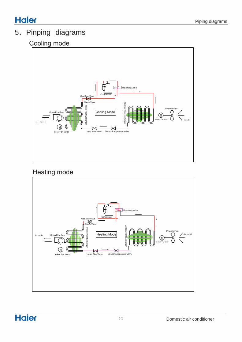
5 Pinping diagrams
Electronic expansion valve
Electronic expansion valve

Connector Wiring diagrams
Domestic air conditioner
6. Printed Circuit Board Connector Wiring Diagram
PCB (1) (Indoor control PCB)
Note: Other designations 1) SW1 Connector for Emergency operation ON / OFF switch 2) SW2 1 Select remote code A or B,
2 Select room card able or disable3,4 Select eeprom code 23 26 33 and 35 ,
3) RV1 Varistor 4) FUSE1 Fuse 3.15A/250VAC
Series PCB connector Connect with load
1 CN21 Connector for power N and L
2 CN52
3 CN27 Connector for ground
4 CN23 Connector for communication between indoor and outdoor unit
5 CN6 Connector for thermistors
6 CN9 Connector for fan motor
7 CN7 Connector for display
8 CN5 Connector for up-down stepmotor
9 CN11 Connector for left-right stepmotor
10 CN2 Connector for wiring-control
11 CN51 Connector for room card
12 CN34 Connector for wifi-control
13 CN1 Reserved connector
13

Connector Wiring diagrams
Domestic air conditioner
Up-down stepmotor
Fan motor
EMERGENCY SWITCH
RECEIVER DISPLAY
AMBIENT TEMP SENSORPIPING TEMP SENSOR
Right stepmotor
left stepmotor
Fresh air
Room card
@
Wifi @
@
ire controller
@Ion generator
14

Functions and Control
Domestic air conditioner
7.Funcitions and Control 7.1 Main functions and control specification
7.1.1 Automatic operation When the running mode is turned to automation after starting the system, the system will first determine the running mode according to the current room temperature and then will run according to the determined mode. Tr in the following selection conditions means room temperature, Ts means setting temperature, Tp means temperature of indoor coil pipe Tr 23 Choose Cooling Mode Tr 23 Choose Heating Mode After turning to the automation mode, the running mode can be switched between cooling mode, fan mode and heating mode according to the change of the indoor ambient temperature. But the automatic conversion between cooling mode and heating mode must be conducted after 15 minutes.
7.1.2 Cooling operation mode Temperature control range: 16 ---30 Temperature difference: 1 * Control features: When Tr input airflow >Ts set temperature , the compressor will be opened, the indoor fan will operate at the set speed and the mode signal will be sent to the outdoor system. When Tr input airflow Ts set temperature , the compressor will be opened, the indoor fan will operate at the set speed and the mode signal will be sent to the outdoor system. The system will keep the original status if Tr= Ts. Airflow speed control: (temperature difference 1 ) Automatic: When Tr Ts+3 , high speed. When Ts+1 Tr<Ts+3 , medium speed When Tr<Ts+1 , low speed When the sensor is off, low speed When the airflow speed has no delay from the high to low switching, the speed should be delayed for 3 minutes (remain at high speed for 3 minutes.) before the next switch. Manus: When the system is operating, you can set the high, medium or low speed manually. (When the sensor is on or off, the system will change the speed 2 seconds after receiving the signal.) *Airgate location control: the location for the airgate can be set according to your needs. *Defrosting function: preventing the frosting on the indoor heat exchanger (when cooling or dehumidifying). When the compressor works continuously for 1/6 minutes (adaptable in EEPROM) and the temperature of the indoor coils has been below zero centigrade for 10 seconds, the compressor will be stopped and the malfunction will be recorded in the malfunction list. The indoor system will continue to run. When the temperature of the indoor coil is raised to 7 , the compressor will be restarted again (the requirement of 3 minutes’ delay should be satisfied.) * timing system on/off function. * Dormant control function.
15
Functions and Control
Domestic air conditioner
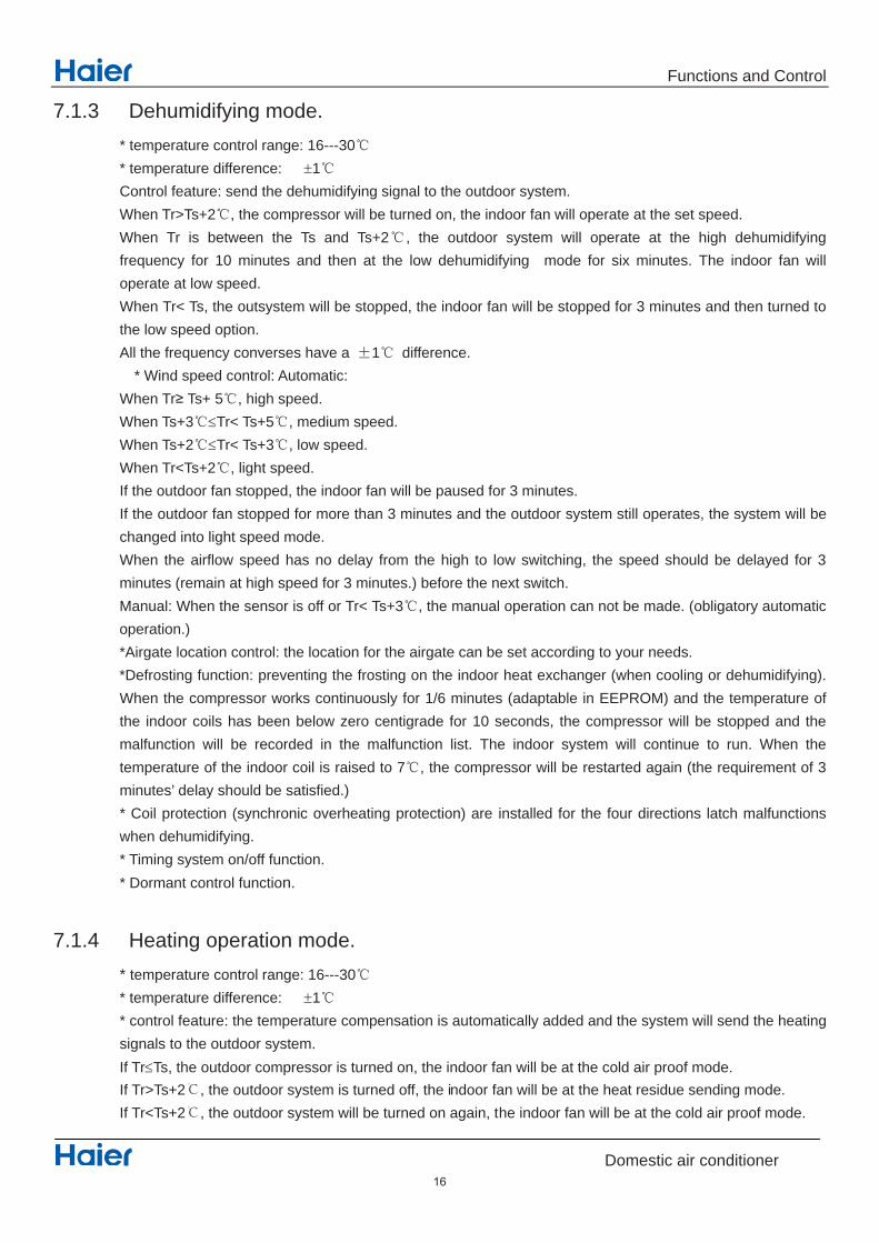
7.1.3 Dehumidifying mode. * temperature control range: 16---30 * temperature difference: 1 Control feature: send the dehumidifying signal to the outdoor system. When Tr>Ts+2 , the compressor will be turned on, the indoor fan will operate at the set speed. When Tr is between the Ts and Ts+2 , the outdoor system will operate at the high dehumidifying frequency for 10 minutes and then at the low dehumidifying mode for six minutes. The indoor fan will operate at low speed. When Tr< Ts, the outsystem will be stopped, the indoor fan will be stopped for 3 minutes and then turned to the low speed option. All the frequency converses have a 1 difference. * Wind speed control: Automatic: When Tr Ts+ 5 , high speed. When Ts+3 Tr< Ts+5 , medium speed. When Ts+2 Tr< Ts+3 , low speed. When Tr<Ts+2 , light speed. If the outdoor fan stopped, the indoor fan will be paused for 3 minutes. If the outdoor fan stopped for more than 3 minutes and the outdoor system still operates, the system will be changed into light speed mode. When the airflow speed has no delay from the high to low switching, the speed should be delayed for 3 minutes (remain at high speed for 3 minutes.) before the next switch. Manual: When the sensor is off or Tr< Ts+3 , the manual operation can not be made. (obligatory automatic operation.) *Airgate location control: the location for the airgate can be set according to your needs. *Defrosting function: preventing the frosting on the indoor heat exchanger (when cooling or dehumidifying). When the compressor works continuously for 1/6 minutes (adaptable in EEPROM) and the temperature of the indoor coils has been below zero centigrade for 10 seconds, the compressor will be stopped and the malfunction will be recorded in the malfunction list. The indoor system will continue to run. When the temperature of the indoor coil is raised to 7 , the compressor will be restarted again (the requirement of 3 minutes’ delay should be satisfied.) * Coil protection (synchronic overheating protection) are installed for the four directions latch malfunctions when dehumidifying. * Timing system on/off function. * Dormant control function.
7.1.4 Heating operation mode. * temperature control range: 16---30 * temperature difference: 1 * control feature: the temperature compensation is automatically added and the system will send the heating signals to the outdoor system. If Tr Ts, the outdoor compressor is turned on, the indoor fan will be at the cold air proof mode. If Tr>Ts+2℃, the outdoor system is turned off, the indoor fan will be at the heat residue sending mode. If Tr<Ts+2℃, the outdoor system will be turned on again, the indoor fan will be at the cold air proof mode.
16

Functions and Control
Domestic air conditioner
*Indoor fan control manual control: You can choose high, medium, low and automatic speed control. Automatic: When Tr<Ts, high speed. When Ts Tr Ts+2 , medium speed. When Tr> Ts+2 , low speed. When the airflow speed has no delay from the high to low switching, the speed should be delayed for 3 minutes (remain at high speed for 3 minutes.) before the next switch. *Airgate location control: the location for the airgate can be set according to your needs. Coldair proof operation 1. The indoor operation within 4 minutes after the start up is as the following diagram, the air speed can be raised only after the speed has reached a certain level.
Set speed Heat start temp 1 Low speed Heat start temp 2 Light speed Heat start temp 3 Fan/off Heat start temp 4 Fan/off
2. 4 minutes after the start up of the indoor fan, the light airflow and the low airflow will be turned to the set speed airflow. 3. In the cold air proof operation, the fan won’t stop after the start up. 4. During the cold air proof operation, the indoor system will continuously send ‘indoor high speed’ signals to the outdoor system. * Residue heat sending. The indoor fan will send the residue heat at a low speed for 12 seconds. If other conditions are satisfied, when the compressor stops, the indoor system will operate at a light speed. The indoor fan will stop when the coil temperature is below the ‘heat start temp 4’. * Defrosting. When the system receives the defrosting signal from outdoors, the indoor fan will stop and the indoor temperature display won’t change. At the time, any indoor coil malfunctions will be neglected. When the outdoor defrosting finishes, the coil malfunction will still be neglected until the compressor has been started up for 30 seconds. The indoor temperature display will not change and the system operates at the cold air proof mode. * Automatic heating temperature compensation: when the system enters the heating mode, the temperature compensation (4) will be added. When the status is switched off, the compensation will be erased.
7.1.5 Strength operation The system enters the mode after receiving the ‘strength signal’. Send strength operation signal to the outdoor system. The mode change finishes the strength operation. Entering ‘mute’, you can have normal operation or signal control such as timing to finish the strength operation.
Keep the high
speed. The fan
doesn’t stop
17

Functions and Control
Domestic air conditioner
When the system is at the automatic option with the strength/ mute function, if the system enters the cooling mode, the cooling strength/ mute function will be offered; if the system enters the heating mode, then the heating strength/ mute function will be offered; if the system enters the airflow mode, there will be no strength/ mute function.
7.1.6 Mute operation The system enters the mode after receiving the ‘mute signal’. a. Mute heating: the airflow speed is slight, the system sends the mute signal to the outdoor system. b. mute cooling: the airflow speed is slight, the system sends the mute signal to the outdoor system. When the compressor operates, the airflow speed is mute speed. EEPROM is adaptable. Mute operation can not work under the dehumidifying and airflow-sending operation.
7.1.7 Air refreshing After receiving the signal from the remote control, (HV series: the background light of the ‘health’ logo is green. HS series: the ‘health’ indicator will be lighted). If the fan operates, the Nano-Aqua operates to realize the ions sending function. If the indoor fan stops, the Nano-Aqua is turned off. When the Nano-Aqua is turned off, if the air refreshing system is turned on, the Nano-Aqua will be turned on when the fan operates.
7.1.8 Timing You can set 24 hours’ on/off timing accordingly. After the setting, the timing indicator will be lightened. Also, the light will be turning off after the timing is finished. The followings are several timing methods. 1.system /on timing: The timing indicator will be lightened and the indoor system is under the waiting mode. The light will be turned off when the timing is finished and the rest of the system will operate under a normal condition. The timing starts since the last reception of the timing signal. 2.system /off timing: When the system is turned on, the timing indicator is lightened, the rest of the system will operated under a normal condition. When set time comes, the indicator light will be turned off and the system will be turned off. If you have set the dormant functions, the order of your settings will be operated according to the timing settings. 3 .system /on and off timing: The settings will be completed according to the orders..
7.1.9 Dormant operation
The dormant timing is an eight hours unadaptable one. The timing signs are shown on the V series board. (RC series show the dormant signal, the timing light is lighted on the 6 lights board). 2.1 Under the cooling/ dehumidifying operation, after the setting of the dormant operation, the set temperature will be raised for 1 centigrade after 1 hour’s operation and will be raised for 1 centigrade 1 hour later. The system will keep this status for 6 hours and then close. 2.2 Under the heating mode, after the setting of the dormant operation, the setting temperature will fall 2 centigrade after 1 hour’s operation and will fall 2 centigrade 1 hour later. 3 hours after the preceding operations, the set temperature will be raised for 1 centigrade and the system will keep this status for 3 hours
18

Functions and Control
Domestic air conditioner
and then close down. 2.3 During the dormant time, except the change of the system mode or a new press on the dormant setting keys, the timing of the 8 hours dormancy will take the first timing as the start time, any presses on other keys will not affect the original timing. 2.4 Indoor fan control under the dormant operation. If the indoor fan is at the high speed before the dormant operation setting, the speed will be turned to medium after the setting. If the fan is at the medium speed before the dormant setting, the speed will be turned to low after the setting. If the fan is at the low speed before the dormant setting, the speed will not change.
7.1.10 Urgent on/off input Press the urgency button the buzzer will ring. The system will enter the automatic mode if you don’t press the button for more than 5 seconds. Under the system off mode, if you press the urgency key for 5 to 10 seconds, the system will start the test operation. Under the system off mode, if you press the urgency key for 10 to 15 seconds, the display screen will show the resume of the last malfunction. If the system is under operation, the press on the urgency key will stop it. Under the system off mode, the display screen will show automatic running sign. Under the system off mode, the system will not receive the remote control signal if the press on the urgency key doesn’t last for 15 seconds or if the key is loosened. Urgency operation: If you press the urgency key for less than 5 seconds, the buzzer will ring when you press the on/off key. The system will enter the urgency operation when the urgency key is loosened. The urgency operation is fully automatic. Test operation. The inlet temperature sensor doesn’t work, the indoor fan and the indoor air direction board motor works synchronically. High speed airflow, cooling, outdoor system on, etc, will send the ambient temperature 30 centigrade and coil temperature 16 centigrade information to the outdoor system. Test operation The defrost protection of the evaporator doesn’t work. The temperature control doesn’t work. The test operation will be finished in 30 minutes. The test operation can be stopped by the relative commands from the remote control.
7.1.11 Low load protection control In order to prevent the frosting of the indoor heat interaction device, the outdoor system will be stopped if the indoor heat interaction temperature is below zero centigrade for 5 minutes, but the fan will continue to operate. The outdoor system will be started again when the heat interaction temperature is above 7 centigrade and the system has been stopped for 3 minutes. The malfunction will be stored in the malfunction resume and will not be revealed.
7.1.12 High load protection control The outdoor system will be stopped if the coil temperature is above 65 for 2 minutes. The indoor fan will be
19
Functions and Control
Domestic air conditioner
keys for 6 times within 7 seconds, the system will feedback with 6 rings. * After the system enters the separate indoor system operation mode, the indoor system will operate according to the set mode and neglect the communication signals of the outdoor system. However, it has to send signals to the outdoor system. * Quitting condition: This mode can be quitted after receiving the quitting signal from the remote control or urgency system. The indoor system thus can quit the single operation mode.
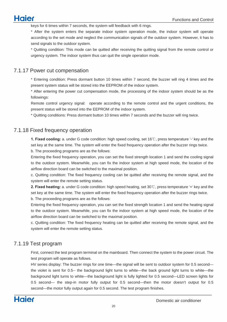
7.1.17 Power cut compensation * Entering condition: Press dormant button 10 times within 7 second, the buzzer will ring 4 times and the present system status will be stored into the EEPROM of the indoor system. * After entering the power cut compensation mode, the processing of the indoor system should be as the followings: Remote control urgency signal: operate according to the remote control and the urgent conditions, the present status will be stored into the EEPROM of the indoor system. * Quitting conditions: Press dormant button 10 times within 7 seconds and the buzzer will ring twice.
7.1.18 Fixed frequency operation 1. Fixed cooling: a. under G code condition: high speed cooling, set 16 , press temperature ‘-‘ key and the set key at the same time. The system will enter the fixed frequency operation after the buzzer rings twice. b. The proceeding programs are as the follows: Entering the fixed frequency operation, you can set the fixed strength location 1 and send the cooling signal to the outdoor system. Meanwhile, you can fix the indoor system at high speed mode, the location of the airflow direction board can be switched to the maximal position. c. Quitting condition: The fixed frequency cooling can be quitted after receiving the remote signal, and the system will enter the remote setting status. 2. Fixed heating: a. under G code condition: high speed heating, set 30 , press temperature ‘+‘ key and the set key at the same time. The system will enter the fixed frequency operation after the buzzer rings twice. b. The proceeding programs are as the follows: Entering the fixed frequency operation, you can set the fixed strength location 1 and send the heating signal to the outdoor system. Meanwhile, you can fix the indoor system at high speed mode, the location of the airflow direction board can be switched to the maximal position. c. Quitting condition: The fixed frequency heating can be quitted after receiving the remote signal, and the system will enter the remote setting status.
7.1.19 Test program
First, connect the test program terminal on the mainboard. Then connect the system to the power circuit. The test program will operate as follows. HV series display: The buzzer rings for one time—the signal will be sent to outdoor system for 0.5 second— the violet is sent for 0.5-- the background light turns to white—the back ground light turns to white—the background light turns to white—the background light is fully lighted for 0.5 second—LED screen lights for 0.5 second— the step-in motor fully output for 0.5 second—then the motor doesn’t output for 0.5 second—the motor fully output again for 0.5 second. The test program finishes.
20

Connector Wiring diagrams
Domestic air conditioner
21
PCB
CN7
CN21
CN52
CN23
CN9
CN27
CN34
CN6
CN5
CN51
CN5
CN2

Functions and Control
Domestic air conditioner
controlled by the thermostat. The outdoor system can be restarted when the coil temperature is below 42 and the system has been stopped for 3 minutes. The malfunction will be stored in the malfunction resume and will not be revealed.
7.1.13 Abnormal operation of indoor system
When the outdoor system operates, if the indoor system operation differs from the outdoor system, the abnormal operation malfunction will be reported. 10s after the report, the indoor system will be closed. Outdoor system mode Indoor system mode conflicts cooling heating yes cooling cooling no cooling airflow no heating heating no heating airflow yes heating cooling yes
7.1.14 Malfunction list resume. Nothing is presented if there is no code list. The malfunction display will automatically finish in 10 seconds. The remote control only receives the signals for stop. According to the signals, the malfunction resume presentation finishes. The resume restores after the power supply restores.
7.1.15 Abnormality confirmation approaches 1. indoor temperature sensor abnormality: Under the operation, the normal temperature ranges from 120 degree to -30 degree. When the temperature goes beyond this range, the abnormality can be confirmed. If the temperature goes back into the range, the system will automatically resume. 2 .indoor heat interaction sensor abnormality: Under the operation, the normal temperature ranges from 120 degree to -30 degree. When the temperature goes beyond this range, the abnormality can be confirmed. If the temperature goes back into the range, the system will automatically resume. 3 .indoor malfunction: Outdoor malfunction: When the indoor system receives the outdoor malfunction codes, it will store the code into E2 for the malfunction list resume. The indoor system will continue to operate according to the original status, the malfunction code will not be revealed or processed. 4. transmission abnormality: If the indoor system can’t receive the outdoor system for 8 minutes, the communication abnormality can be confirmed and reported and the outdoor system will be stopped.
7.1.16 Single indoor system operation
* Enter condition: First, set the high speed airflow and 30 centigrade set temperature, then press the dormant
22

Functions and Control
Domestic air conditioner
7.1.20 Time cutting function: Connect the test program terminal on the mainboard after connecting the system to the power circuit. The CPU of the main control will be 60 times faster.
7.2 Value of thermistor Room sensor and Pipe Sensor
R25 =10K 3% B25 /50 =3700K 3%
Temp.(( )) Max.(K ) Normal(K ) Min.(K ) Tolerance( )
-30 165.2170 147.9497 132.3678 -1.94 1.75
-29 155.5754 139.5600 125.0806 -1.93 1.74
-28 146.5609 131.7022 118.2434 -1.91 1.73
-27 138.1285 124.3392 111.8256 -1.89 1.71
-26 130.2371 117.4366 105.7989 -1.87 1.70
-25 122.8484 110.9627 100.1367 -1.85 1.69
-24 115.9272 104.8882 94.8149 -1.83 1.67
-23 109.4410 99.1858 89.8106 -1.81 1.66
-22 103.3598 93.8305 85.1031 -1.80 1.64
-21 97.6556 88.7989 80.6728 -1.78 1.63
-20 92.3028 84.0695 76.5017 -1.76 1.62
-19 87.2775 79.6222 72.5729 -1.74 1.60
-18 82.5577 75.4384 68.8710 -1.72 1.59
-17 78.1230 71.5010 65.3815 -1.70 1.57
-16 73.9543 67.7939 62.0907 -1.68 1.55
-15 70.0342 64.3023 58.9863 -1.66 1.54
-14 66.3463 61.0123 56.0565 -1.64 1.52
-13 62.8755 57.9110 53.2905 -1.62 1.51
-12 59.6076 54.9866 50.6781 -1.60 1.49
-11 56.5296 52.2278 48.2099 -1.58 1.47
-10 53.6294 49.6244 45.8771 -1.56 1.46
-9 50.8956 47.1666 43.6714 -1.54 1.44
-8 48.3178 44.8454 41.5851 -1.51 1.42
-7 45.8860 42.6525 39.6112 -1.49 1.40
-6 43.5912 40.5800 37.7429 -1.47 1.39
-5 41.4249 38.6207 35.9739 -1.45 1.37
-4 39.3792 36.7676 34.2983 -1.43 1.35
-3 37.4465 35.0144 32.7108 -1.41 1.33
-2 35.6202 33.3552 31.2062 -1.38 1.31
-1 33.8936 31.7844 29.7796 -1.36 1.29
0 32.2608 30.2968 28.4267 -1.34 1.28
1 30.7162 28.8875 27.1431 -1.32 1.26
23

Functions and Control
Domestic air conditioner
2 29.2545 27.5519 25.9250 -1.29 1.24
3 27.8708 26.2858 24.7686 -1.27 1.22
4 26.5605 25.0851 23.6704 -1.25 1.20
5 25.3193 23.9462 22.6273 -1.23 1.18
6 24.1432 22.8656 21.6361 -1.20 1.16
7 23.0284 21.8398 20.6939 -1.18 1.14
8 21.9714 20.8659 19.7982 -1.15 1.12
9 20.9688 19.9409 18.9463 -1.13 1.09
10 20.0176 19.0621 18.1358 -1.11 1.07
11 19.1149 18.2270 17.3646 -1.08 1.05
12 18.2580 17.4331 16.6305 -1.06 1.03
13 17.4442 16.6782 15.9315 -1.03 1.01
14 16.6711 15.9601 15.2657 -1.01 0.99
15 15.9366 15.2770 14.6315 -0.98 0.96
16 15.2385 14.6268 14.0271 -0.96 0.94
17 14.5748 14.0079 13.4510 -0.93 0.92
18 13.9436 13.4185 12.9017 -0.91 0.90
19 13.3431 12.8572 12.3778 -0.88 0.87
20 12.7718 12.3223 11.8780 -0.86 0.85
21 12.2280 11.8126 11.4011 -0.83 0.83
22 11.7102 11.3267 10.9459 -0.81 0.80
23 11.2172 10.8634 10.5114 -0.78 0.78
24 10.7475 10.4216 10.0964 -0.75 0.75
25 10.3000 10.0000 9.7000 -0.75 0.75
26 9.8975 9.5974 9.2980 -0.76 0.76
27 9.5129 9.2132 8.9148 -0.80 0.80
28 9.1454 8.8465 8.5496 -0.84 0.83
29 8.7942 8.4964 8.2013 -0.87 0.86
30 8.4583 8.1621 7.8691 -0.91 0.90
31 8.1371 7.8428 7.5522 -0.95 0.93
32 7.8299 7.5377 7.2498 -0.98 0.97
33 7.5359 7.2461 6.9611 -1.02 1.00
34 7.2546 6.9673 6.6854 -1.06 1.04
35 6.9852 6.7008 6.4222 -1.10 1.07
36 6.7273 6.4459 6.1707 -1.13 1.11
37 6.4803 6.2021 5.9304 -1.17 1.14
38 6.2437 5.9687 5.7007 -1.21 1.18
39 6.0170 5.7454 5.4812 -1.25 1.22
40 5.7997 5.5316 5.2712 -1.29 1.25
41 5.5914 5.3269 5.0704 -1.33 1.29
42 5.3916 5.1308 4.8783 -1.37 1.33
43 5.2001 4.9430 4.6944 -1.41 1.36
44 5.0163 4.7630 4.5185 -1.45 1.40
24

Functions and Control
Domestic air conditioner
45 4.8400 4.5905 4.3500 -1.49 1.44
46 4.6708 4.4252 4.1887 -1.53 1.47
47 4.5083 4.2666 4.0342 -1.57 1.51
48 4.3524 4.1145 3.8862 -1.61 1.55
49 4.2026 3.9686 3.7443 -1.65 1.59
50 4.0588 3.8287 3.6084 -1.70 1.62
51 3.9206 3.6943 3.4780 -1.74 1.66
52 3.7878 3.5654 3.3531 -1.78 1.70
53 3.6601 3.4416 3.2332 -1.82 1.74
54 3.5374 3.3227 3.1183 -1.87 1.78
55 3.4195 3.2085 3.0079 -1.91 1.82
56 3.3060 3.0989 2.9021 -1.95 1.85
57 3.1969 2.9935 2.8005 -2.00 1.89
58 3.0919 2.8922 2.7029 -2.04 1.93
59 2.9909 2.7948 2.6092 -2.08 1.97
60 2.8936 2.7012 2.5193 -2.13 2.01
61 2.8000 2.6112 2.4328 -2.17 2.05
62 2.7099 2.5246 2.3498 -2.22 2.09
63 2.6232 2.4413 2.2700 -2.26 2.13
64 2.5396 2.3611 2.1932 -2.31 2.17
65 2.4591 2.2840 2.1195 -2.36 2.21
66 2.3815 2.2098 2.0486 -2.40 2.25
67 2.3068 2.1383 1.9803 -2.45 2.29
68 2.2347 2.0695 1.9147 -2.49 2.34
69 2.1652 2.0032 1.8516 -2.54 2.38
70 2.0983 1.9393 1.7908 -2.59 2.42
71 2.0337 1.8778 1.7324 -2.63 2.46
72 1.9714 1.8186 1.6761 -2.68 2.50
73 1.9113 1.7614 1.6219 -2.73 2.54
74 1.8533 1.7064 1.5697 -2.78 2.58
75 1.7974 1.6533 1.5194 -2.83 2.63
76 1.7434 1.6021 1.4710 -2.88 2.67
77 1.6913 1.5528 1.4243 -2.92 2.71
78 1.6409 1.5051 1.3794 -2.97 2.75
79 1.5923 1.4592 1.3360 -3.02 2.80
80 1.5454 1.4149 1.2942 -3.07 2.84
81 1.5000 1.3721 1.2540 -3.12 2.88
82 1.4562 1.3308 1.2151 -3.17 2.93
83 1.4139 1.2910 1.1776 -3.22 2.97
84 1.3730 1.2525 1.1415 -3.27 3.01
85 1.3335 1.2153 1.1066 -3.32 3.06
86 1.2953 1.1794 1.0730 -3.38 3.10
87 1.2583 1.1448 1.0405 -3.43 3.15
25

Functions and Control
Domestic air conditioner
88 1.2226 1.1113 1.0092 -3.48 3.19
89 1.1880 1.0789 0.9789 -3.53 3.24
90 1.1546 1.0476 0.9497 -3.58 3.28
91 1.1223 1.0174 0.9215 -3.64 3.33
92 1.0910 0.9882 0.8942 -3.69 3.37
93 1.0607 0.9599 0.8679 -3.74 3.42
94 1.0314 0.9326 0.8424 -3.80 3.46
95 1.0030 0.9061 0.8179 -3.85 3.51
96 0.9756 0.8806 0.7941 -3.90 3.55
97 0.9490 0.8558 0.7711 -3.96 3.60
98 0.9232 0.8319 0.7489 -4.01 3.64
99 0.8983 0.8088 0.7275 -4.07 3.69
100 0.8741 0.7863 0.7067 -4.12 3.74
101 0.8507 0.7646 0.6867 -4.18 3.78
102 0.8281 0.7436 0.6672 -4.23 3.83
103 0.8061 0.7233 0.6484 -4.29 3.88
104 0.7848 0.7036 0.6303 -4.34 3.92
105 0.7641 0.6845 0.6127 -4.40 3.97
106 0.7441 0.6661 0.5957 -4.46 4.02
107 0.7247 0.6482 0.5792 -4.51 4.07
108 0.7059 0.6308 0.5632 -4.57 4.12
109 0.6877 0.6140 0.5478 -4.63 4.16
110 0.6700 0.5977 0.5328 -4.69 4.21
111 0.6528 0.5820 0.5183 -4.74 4.26
112 0.6361 0.5667 0.5043 -4.80 4.31
113 0.6200 0.5518 0.4907 -4.86 4.36
114 0.6043 0.5374 0.4775 -4.92 4.41
115 0.5891 0.5235 0.4648 -4.98 4.45
116 0.5743 0.5100 0.4524 -5.04 4.50
117 0.5600 0.4968 0.4404 -5.10 4.55
118 0.5460 0.4841 0.4288 -5.16 4.60
119 0.5325 0.4717 0.4175 -5.22 4.65
120 0.5194 0.4597 0.4066 -5.28 4.70
26

System configuration
Domestic air conditioner
8 System configuration
After the installation and test operation of the room air conditioner have been completed, it should be operated and handled as described below. Every user would like to know the correct method of operation of the room air conditioner, to check if it is capable of cooling(or heating) well, and to know a clever method of using it. In order to meet this expectation of the users, giving sufficient explanations taking enough time can be said to reduce about 80% of the requests for servicing. However good the installation work is and however good the functions are, the customer may blame either the room air conditioner or its installation work because of improper handling. The installation work and handing over of the unit can only be considered to have been completed when its handling has been explained to the user without using technical terms but giving full knowledge of the equipment.
27
Seivice diagnosis
Domestic air conditioner
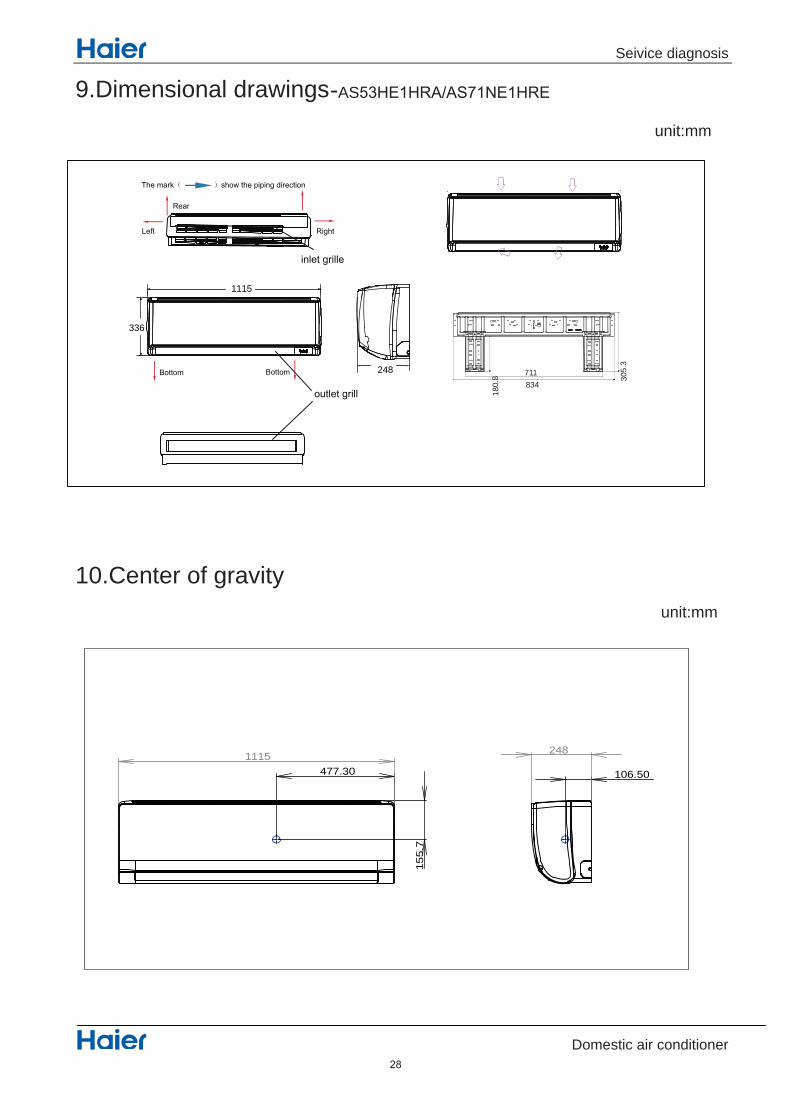
9.Dimensional drawings-AS53HE1HRA/AS71NE1HRE
10.Center of gravity
28
unit:mm
unit:mm
1115
248
336
711834
8.081
3. 503
1115477.30
155.
7
248
106.50

Seivice diagnosis
Domestic air conditioner
11 Service Diagnosis
11.1 Caution for Diagnosis The operation lamp flashes when any of the following errors is detected. 1. When a protection device of the indoor or outdoor unit is activated or when the thermistor malfunctions, disabling equipment operation. 2. When a signal transmission error occurs between the indoor and outdoor units. In either case, conduct the diagnostic procedure described in the following pages.
11.2 Parameter of primary electronic appliance
11.3 Problem Symptoms and Measures Symptom Check Item Details of Measure
None of the units operates
Check the power supply. Check to make sure that the rated voltage is supplied.
Check the indoor PCB Check to make sure that the indoor PCB is broken
Operation sometimes stops.
Check the power supply. A power failure of 2 to 10 cycles can stop air conditioner operation.
Equipment operates but does not cool, or does not heat (only for heat pump)
Check for faulty operation of the electronic expansion valve.
Set the units to cooling operation, and compare the temperatures of the liquid side connection pipes of the connection section among rooms to check the opening and closing operation of the electronic expansion valves of the individual units.
Diagnosis by service port pressure and operating current.
Check for insufficient gas.
Large operating noise and vibrations
Check the installation condition.
Check to make sure that the required spaces for installation (specified in the Technical Guide, etc.) are provided.
29
Seivice diagnosis
Domestic air conditioner
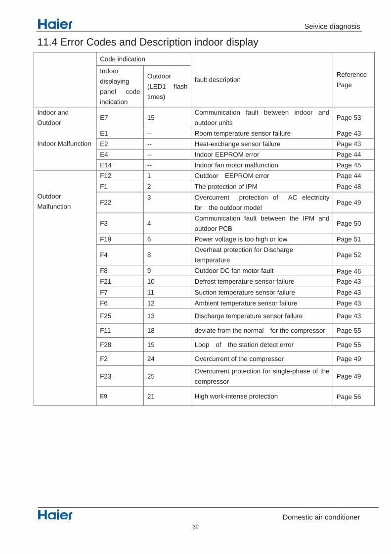
11.4 Error Codes and Description indoor display Code indication
fault description Reference Page
Indoor displaying panel code indication
Outdoor (LED1 flash times)
Indoor and Outdoor
E7 15 Communication fault between indoor and outdoor units
Page 53
Indoor Malfunction
E1 -- Room temperature sensor failure Page 43 E2 -- Heat-exchange sensor failure Page 43
44 egaP rorre MORPEE roodnI -- 4EE14 -- Indoor fan motor malfunction Page 45
Outdoor Malfunction
F12 1 Outdoor EEPROM error Page 44 F1 2 48 egaP MPI fo noitcetorp ehT
F22 3 Overcurrent protection of AC electricity
for the outdoor model Page 49
F3 4 Communication fault between the IPM and outdoor PCB
Page 50
F19 6 Power voltage is too high or low Page 51
F4 8 Overheat protection for Discharge temperature
Page 52
F8 9 Outdoor DC fan motor fault F21 10 Defrost temperature sensor failure Page 43F7 11 Suction temperature sensor failure Page 43F6 12 Ambient temperature sensor failure Page 43
F25 13 Discharge temperature sensor failure Page 43
F11 18 deviate from the normal for the compressor Page 55
F28 19 Loop of the station detect error Page 55
F2 24 Overcurrent of the compressor Page 49
F23 25 Overcurrent protection for single-phase of the compressor
Page 49
E9 21 High work-intense protection
30
Page 46
Page 56
Seivice diagnosis
Domestic air conditioner
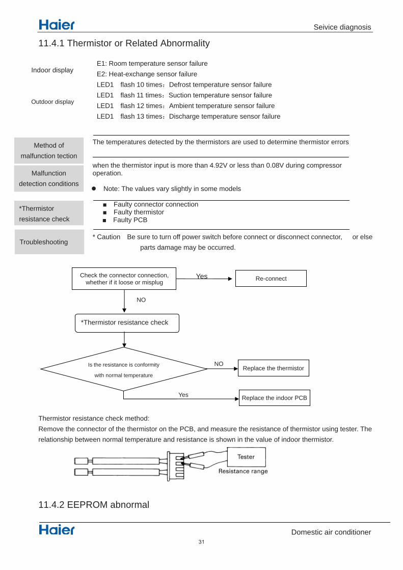
11.4.1 Thermistor or Related Abnormality
The temperatures detected by the thermistors are used to determine thermistor errors when the thermistor input is more than 4.92V or less than 0.08V during compressor operation.
Note: The values vary slightly in some models
Faulty connector connection Faulty thermistor
Faulty PCB * Caution Be sure to turn off power switch before connect or disconnect connector, or else
parts damage may be occurred.
Thermistor resistance check method: Remove the connector of the thermistor on the PCB, and measure the resistance of thermistor using tester. The relationship between normal temperature and resistance is shown in the value of indoor thermistor.
11.4.2 EEPROM abnormal
*Thermistor resistance check
Yes
NO
Yes
Check the connector connection, whether if it loose or misplug Re-connect
NO
Replace the thermistor
Replace the indoor PCB
Is the resistance is conformity
with normal temperature
Method of malfunction tection
Malfunction detection conditions
*Thermistor resistance check
Yes Troubleshooting
E1: Room temperature sensor failure E2: Heat-exchange sensor failure LED1 flash 10 times Defrost temperature sensor failure LED1 flash 11 times Suction temperature sensor failure LED1 flash 12 times Ambient temperature sensor failure LED1 flash 13 times Discharge temperature sensor failure
Indoor display
Outdoor display
31

Seivice diagnosis
Domestic air conditioner
Indoor Display E4: indoor EEPROM error outdoor display F12: Outdoor EEPROM error; Outdoor LED1 flash 1 times
Method of malfunction detection
Malfunction detection conditions
Supposed causes
Troubleshooting
The Data detected by the EEPROM are used to determine MCU
when the data of EEPROM is error or the EEPROM is damaged
Faulty EEPROM data Faulty EEPROM Faulty PCB
* Caution Be sure to turn off power switch before connect or disconnect connector, or parts damage may be occurred.
Replace the indoor or outdoor mainboard
32

Seivice diagnosis
Domestic air conditioner
11.4.3 Indoor AC fan motor malfunctionIndoor Display E14
Check whether terminals
on indoor pcb is well?
Electrify the machine again and turn it on in the cooling operation,
Measure voltage between the positions 1and 3 of Terminal CN5 on
the indoor PCB
the voltage is about 90-220vac
check whether motor can run
when turn on the unit
the indoor motor is damaged and need replace
YesMeasure whether there is voltage pulse(0-5VDC)
between the positions middle wire and black wire
of Terminal CN2 on the indoor PCB
the indoor pcb is damaged and need replace
Pull out the terminals on the indoor
mainboard and reinsert them.
Is it ok?
Method of malfunction detection
Malfunction detection conditions
Troubleshooting
The fan speed detected by the Hall IC during fan motor running which is used to determine the fan motor operating
When there is no fan speed feedback signal within 2 minutes
Operation halt due to breaking of wire inside the fan motor. Fan motor overheat protection Operation halt due to breaking of the fan motor lead wires Detection error due to faulty indoor unit PCB
Supposed causes
* Caution Be sure to turn off power switch before connect or disconnect connector, or else parts damage may be caused
33

Seivice diagnosis
Domestic air conditioner
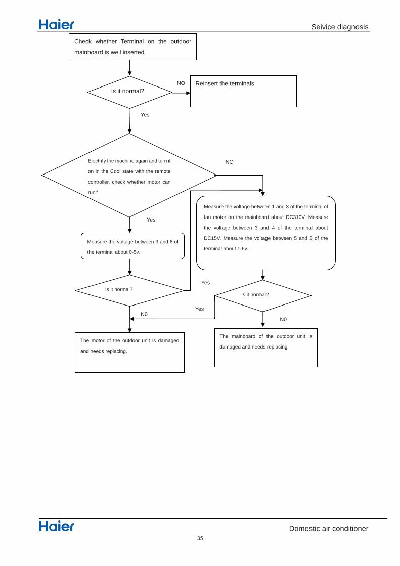
11.4.4 Outdoor DC fan motor fault
Method of malfunction detection
Malfunction detection conditions
Troubleshooting
DC fan motor is detected by checking the fan running condition and so on
when the data of EEPROM is error or the EEPROM is damaged
DC fan motor protection dues to the DC fan motor faulty DC fan motor protection dues to faulty PCB Supposed causes
* Caution Be sure to turn off power switch before connect or disconnect connector, or parts damage
may be occurred.
LED1 flash 9 times Outdoor diplay
34
Seivice diagnosis
Domestic air conditioner
Check whether Terminal on the outdoor
mainboard is well inserted.
Is it normal?
Yes
NO Reinsert the terminals
Electrify the machine again and turn it
on in the Cool state with the remote
controller. check whether motor can
run
Yes
Measure the voltage between 3 and 6 of
the terminal about 0-5v.
Is it normal?
N0
The motor of the outdoor unit is damaged
and needs replacing.
Measure the voltage between 1 and 3 of the terminal of
fan motor on the mainboard about DC310V, Measure
the voltage between 3 and 4 of the terminal about
DC15V. Measure the voltage between 5 and 3 of the
terminal about 1-6v.
NO
Is it normal?
The mainboard of the outdoor unit is
damaged and needs replacing
N0
Yes
Yes
35
Seivice diagnosis
Domestic air conditioner
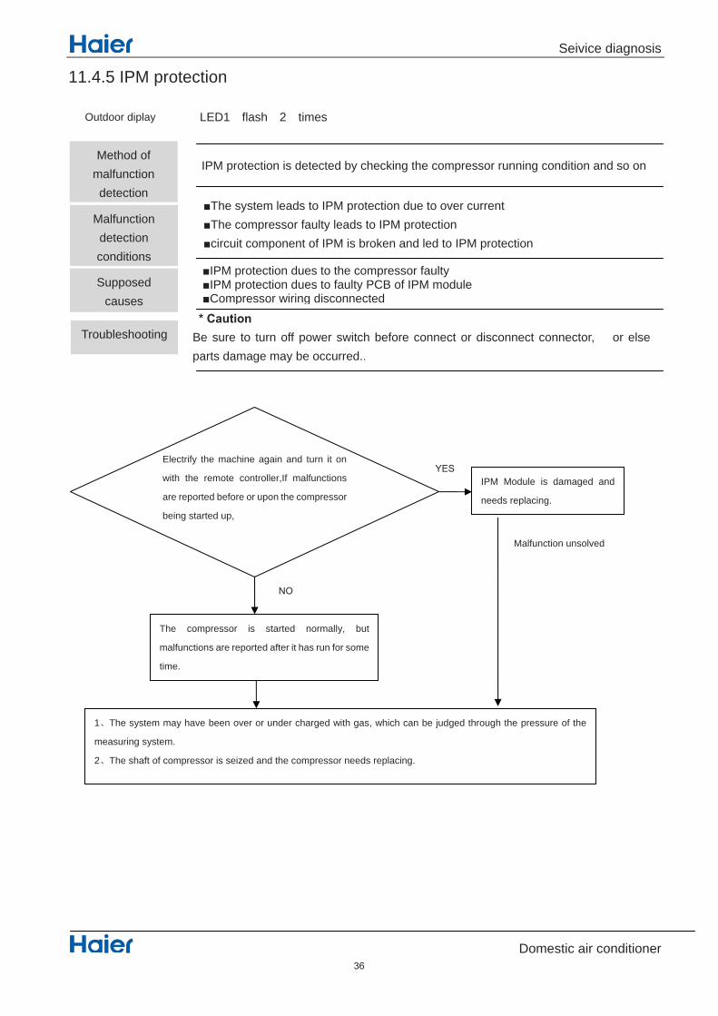
11.4.5 IPM protection
Electrify the machine again and turn it on
with the remote controller,If malfunctions
are reported before or upon the compressor
being started up,
IPM Module is damaged and
needs replacing.
1 The system may have been over or under charged with gas, which can be judged through the pressure of the
measuring system.
2 The shaft of compressor is seized and the compressor needs replacing.
The compressor is started normally, but
malfunctions are reported after it has run for some
time.
Malfunction unsolved
Method of malfunction detection
Malfunction detection conditions
Troubleshooting
IPM protection is detected by checking the compressor running condition and so on
The system leads to IPM protection due to over current The compressor faulty leads to IPM protection circuit component of IPM is broken and led to IPM protection
IPM protection dues to the compressor faulty IPM protection dues to faulty PCB of IPM module Compressor wiring disconnected
Supposed causes
* Caution Be sure to turn off power switch before connect or disconnect connector, or else parts damage may be occurred..
LED1 flash 2 timesOutdoor diplay
36
Seivice diagnosis
Domestic air conditioner
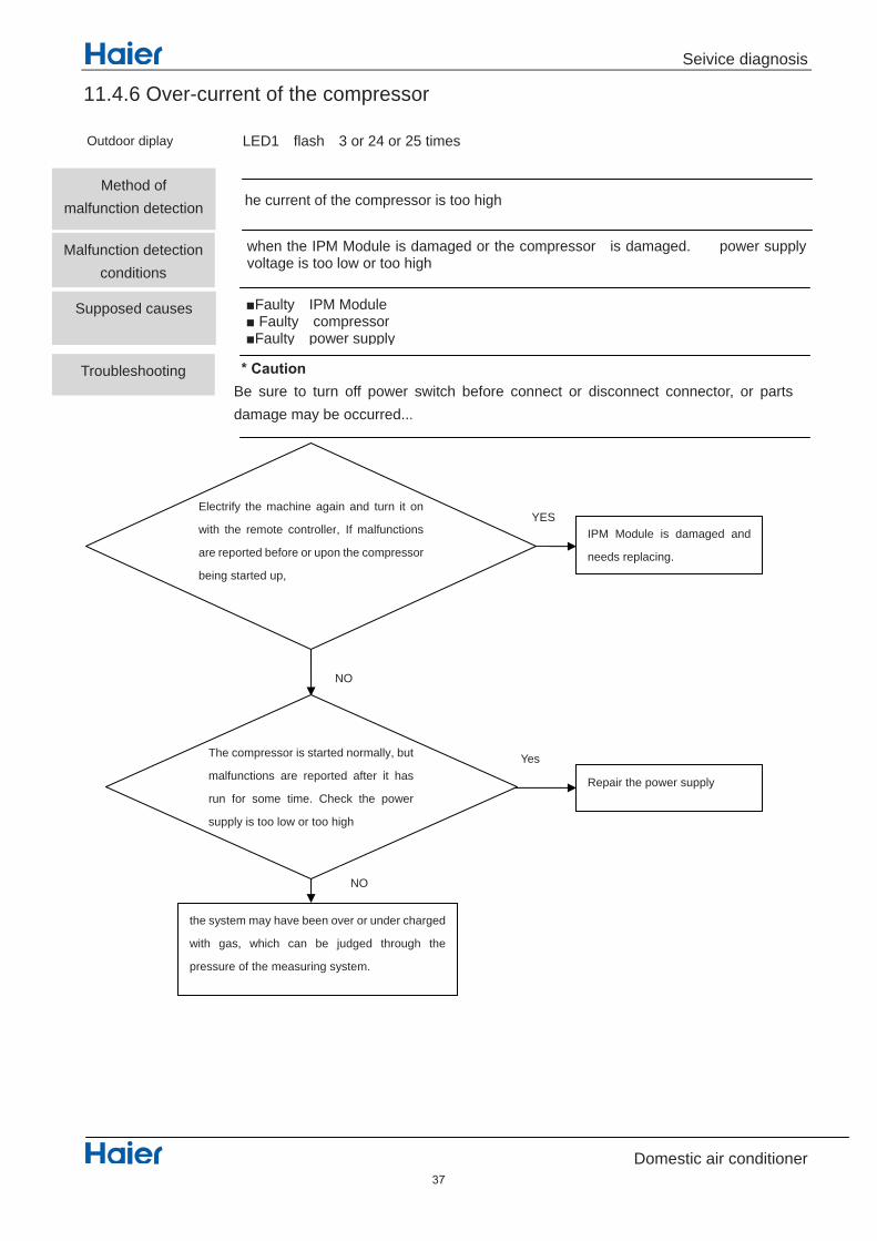
11.4.6 Over-current of the compressor
Electrify the machine again and turn it on
with the remote controller, If malfunctions
are reported before or upon the compressor
being started up,
IPM Module is damaged and
needs replacing.
Repair the power supply
the system may have been over or under charged
with gas, which can be judged through the
pressure of the measuring system.
YES
NO
Yes
NO
The compressor is started normally, but
malfunctions are reported after it has
run for some time. Check the power
supply is too low or too high
NO
Method of malfunction detection
Malfunction detection conditions
Troubleshooting
he current of the compressor is too high
when the IPM Module is damaged or the compressor is damaged. power supply voltage is too low or too high
Supposed causes
LED1 flash 3 or 24 or 25 timesOutdoor diplay
Faulty IPM Module Faulty compressor Faulty power supply
* Caution Be sure to turn off power switch before connect or disconnect connector, or parts damage may be occurred...
37

Seivice diagnosis
Domestic air conditioner
11.4.7 The communication fault between IPM and outdoor PCB
1) Check whether Terminal CN23 and CN24 on the outdoor mainboard
CN10 and CN11 on IPM module
2) Check whether the connected wire between IPM and outdoor
Are they good?
Electrify the machine again and turn it
on, Check whether the voltage between
1 and 2 of Terminal CN23 is about DC5V,
Check whether the voltage between2
and 3 of Terminal CN23 is about DC15V,
Replace the outdoor mainboard with a new one
Replace the outdoor IPM module
with a new one.
YES
NO
NO
YES
Malfunction unsolved
1) Pull out and reinsert the terminals.
2) Replace connected wire
Method of malfunction detection
Malfunction detection conditions
Troubleshooting
Communication is detected by checking the IPM module and the outdoor PCB
The outdoor PCB broken leads to communication fault The IPM module broken leads to communication fault
The outdoor PCB is broken The IPM module is broken Communication wiring disconnected
Supposed causes
* Caution Be sure to turn off power switch before connect or disconnect connector, or else parts damage may be occurred
LED1 flash 4 timesOutdoor diplay
38

Seivice diagnosis
Domestic air conditioner
11.4.8 Power Supply Over or under voltage fault
Electrify the machine again and turn it on with
the remote controller. Check whether the
compressor is started normally
Is it ok?
Yes Maybe there is some disturbance
NO
No
~230 is ok?
Yes
Yes
This question may be caused by the power. Repair
the power supply.
NO
Change the IPM module
Change the IPM module
Test the outdoor power supply
(+310VDC) with a multimeter.
check whether the power
is >150 V or <390V?
Method of malfunction detection
Malfunction detection conditions
Troubleshooting
An abnormal voltage rise or fall is detected by checking the specified voltage detection
An voltage signal is fed from the voltage detection circuit to the microcomputer
Supply voltage not as specified. The IPM module is broken. The outdoor PCB is broken.
Supposed causes
* Caution Be sure to turn off power switch before connect or disconnect connector, or else parts damage may be occurred.
LED1 flash 6 times The power supply is over voltageOutdoor diplay
39

Seivice diagnosis
Domestic air conditioner
11.4.9 Overheat Protection For Discharge Temperature
Electrify the machine again and turn it on with the remote controller,
then measure the temperature at the exhaust temperature sensor of
the compressor on the outdoor unit
the temperature exceeds
110 shortly after the
machine starts up?
1) The cryogen may have been leaked during
installation, or there may be leakage in the piping
system.
2) There may be other causes to make the exhaust
temperature too high.
Malfunctions occur after running for some time even
though the measured temperature is below 110 . Pull
out the exhaust sensor and measure its resistance at
standard temperatures according to the
resistance-temperature table
the results deviate
much?
The sensor is damaged. Replace the sensor
with a new one.
The outdoor mainboard is damaged and needs be
replaced
YES
NO
NO
YES
Method of malfunction detection
Malfunction detection conditions
Troubleshooting
The Discharge temperature control is checked with the temperature being detected by the Discharge pipe thermistor
when the compressor discharge temperature is above 110
Electronic expansion valve defective Faulty thermistor Faulty PCB
Supposed causes
* Caution Be sure to turn off power switch before connect or disconnect connector, or else parts damage may be occurred.
LED1 flash 8 timesOutdoor diplay
40

Seivice diagnosis
Domestic air conditioner
11.4.10 The communication fault between indoor and outdoor
NO
A
Yes
NO
Yes
No
YES
Restart the a/c and it
becomes normally.
If starting up normally, but
malfunction occurs again after a
while
Check whether the linking cable
between the indoor and outdoor is well
connected or whether its core wires are
well insulated.
The outdoor mainboard needs
dehumidification.
The outdoor mainboard needs
dedust.
1. Reconnect the linking cable;
2. Replace the linking cable with new
one.
Method of malfunction detection
Malfunction detection conditions
Troubleshooting
Communication is detected by checking the indoor PCB and the outdoor PCB
The outdoor PCB broken leads to communication fault The indoor PCB broken leads to communication fault
Communication wiring disconnected The indoor PCB is broken The outdoor PCB is broken The module PCB is broken
Supposed causes
* Caution Be sure to turn off power switch before connect or disconnect connector, or else parts damage may be occurred.
E7 LED1 flash 15 times
indoor diplay
Outdoor diplay
41

Seivice diagnosis
Domestic air conditioner
A NO
YES
Yes Check the indoor mainboard.
No
If the voltage is of a constant
value of 0V DCto5V DC
YES
Measure the voltage between Jumpers 3 and
4 of IC1 on the indoor mainboard with a
multimeter.
NO
The outdoor mainboard is damaged;
Replace them with a new one.
Measure the AC voltage between positions 1
and 3 on the terminal of outdoor unit with a
multimeter.
If 230VAC is available but 310DC not,
the power module is damaged, replace it
with a new one.
Test the outdoor power supply (230VAC
and +310VDC) with a multimeter.
The outdoor mainboard is damaged; replace
it with a new one.
The indoor mainboard is damaged; replace
it with a new one.
If the value varies between 0 and 80 VAC, the
outdoor mainboard is damaged, replace it
with a new one.
If the value is constant at about 30V, the
indoor mainboard is damaged, replace it with
a new one.
If both 230VAC and 310DC are
available, measure +12V
(from7805) is available.
42
Circuit diagrams
Domestic air conditioner
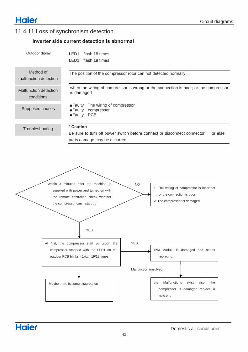
11.4.11 Loss of synchronism detection Inverter side current detection is abnormal
Within 3 minutes after the machine is
supplied with power and turned on with
the remote controller, check whether
the compressor can start up
1. The wiring of compressor is incorrect
or the connection is poor;
2. The compressor is damaged
At first, the compressor start up ,soon the
compressor stopped with the LED1 on the
outdoor PCB blinks 1Hz 19/18 times
IPM Module is damaged and needs
replacing.
the Malfunctions exist also, the
compressor is damaged replace a
new one
YES
NO
YES
Malfunction unsolved
Maybe there is some disturbance
Method of malfunction detection
Malfunction detection conditions
Troubleshooting
The position of the compressor rotor can not detected normally
when the wiring of compressor is wrong or the connection is poor; or the compressor is damaged
Faulty The wiring of compressor Faulty compressor Faulty PCB
Supposed causes
* Caution Be sure to turn off power switch before connect or disconnect connector, or else parts damage may be occurred.
LED1 flash 18 times LED1 flash 19 times
Outdoor diplay
43

Circuit diagrams
Domestic air conditioner
11.4.12 High work-intense protection
Electrify the machine again and turn it on with the
remote controller, check whether the wind
temperature is below 65
The malfunction is reported
after the machine has run
for some time?
1 Check room temperature and
pipe temperature sensor.
2 the temperature monitoring circuit
of the indoor mainboard
The indoor unit blows poorly
due to blocked filters or poor
condition of the fan?
1) Clean the filters
2) Reinstall the fan.
Use some tools to measure the pressure of system
YES
NO
YES
NO
Method of malfunction detection
Malfunction detection conditions
Troubleshooting
High work-intense control is activated in the heating mode if the temperature being sensed by the heat exchanger thermistor exceeds the limit.
Activated when the temperature being sensed by the heat exchanger rises above 65 twice in 30 minutes.
Faulty electronic expansion valve Dirty heat exchanger Faulty heat-exchange sensor Insufficient gas
Supposed causes
* Caution Be sure to turn off power switch before connect or disconnect connector, or else parts damage may be occurred.
LED1 flash 21 timesOutdoor diplay
44

Circuit diagrams
Domestic air conditioner
12. Circuit diagrams
45

Circuit diagrams
Domestic air conditioner
46

Circuit diagrams
Domestic air conditioner
Sincere Forever
Haier Group
Haier Industrial Park, No.1, Haier Road
266101, Qingdao, China_
Http //www.haier.com
Edited by : Zou Na
Signed by : Shen Weijie
Approved by: He Shiquan

Wall Mounted Type DC Inverter FREE MATCH N-Series
SERIES:70N
2016 (Qingdao Haier Air Conditioner General corp. , Ltd)
All rights reserved. Unauthorized copying and distribution is a violation of law
Haier Group Version V1 Date 2016-05-12
This service information is designed for experienced repair technicians only and is not designed for use by the general public.
It does not contain warnings or cautions to advise non-technical individuals of potential dangers in attempting to service a product.
Products powered by electricity should be serviced or repaired only by experienced professional technicians. Any attempt to service or.
Repair the product or products dealt with in this service information by anyone else could result in serious injury or death
WARNING
1
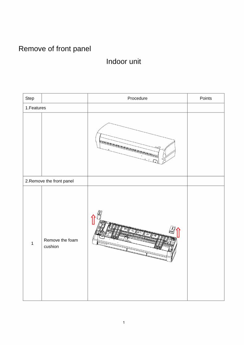
Remove of front panel
Indoor unit
Step Procedure Points
1.Features
2.Remove the front panel
1Remove the foamcushion

2
Step Procedure Points
2
3
4
Hold the front panel bythe tabs on the bothsides and lift it until itstops with a click. Loosen the screw and liftup the casing cover
Loosen the screw and lift up the control boxcover
Pull the wires out of thecontrol box and thenrelease the pivots onboth sides of the unit to remove the frontpanel.

3
Remove the air filters and horizontal flapStep Procedure Points
1Lift an air filter upwardsslightly and then pull it out downwards
Remove the horizontal flap
1
Release the side of pivotand then Release theCenter of the pivot. Bend the horizontalblade slightly andremove it.
The horizontalflap is Double

4
Remove the casingStep Procedure Points
1
2
Release the screwcovers(3EA)
Loosen the markedScrew (7EA)

5
Step Procedure Points
3
Release the markedhooks (4EA) and thenPull the front grille outHorizontally andremove it
When assembling,install the frontgrille horizontallyso as not to stuffthe flap inside.When assembling,make sure the fourhooks are caughtproperly.
Hook (4EA)
Hole (4EA)

6
Release stepping motor and control boxStep Procedure Points
1
2
Loosen the stepping motor screws (4EA)and then Release thestepping motor
Loosen the controlBox screws (2EA)And then pull it.
7
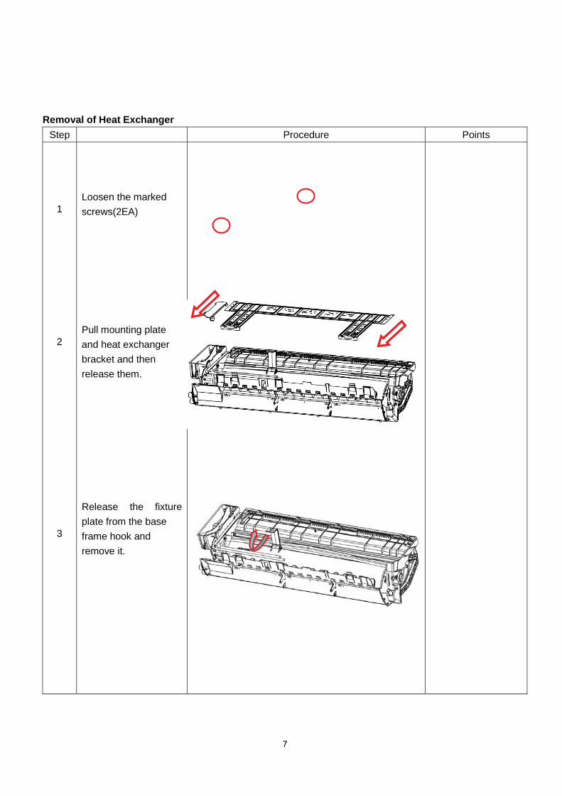
Removal of Heat ExchangerStep Procedure Points
1
2
3
Loosen the markedscrews(2EA)
Pull mounting plateand heat exchangerbracket and thenrelease them.
Release the fixture plate from the baseframe hook andremove it.
8
Step Procedure Points
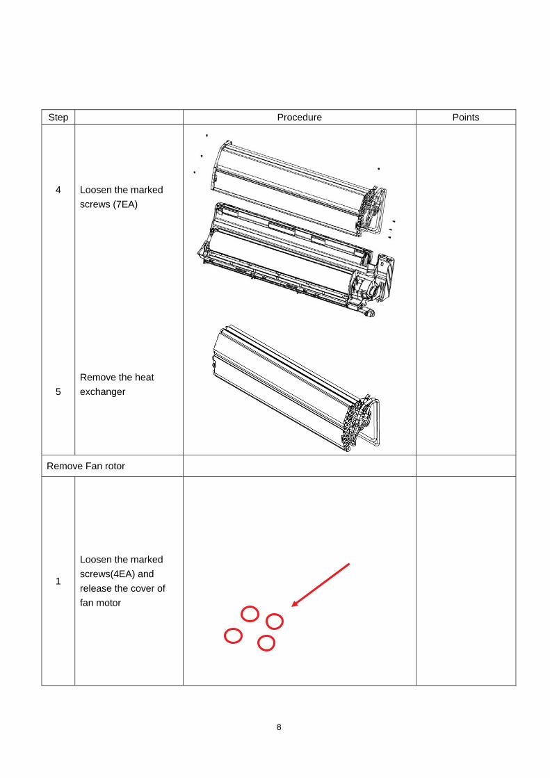
4
5
Loosen the markedscrews (7EA)
Remove the heatexchanger
Remove Fan rotor
1
Loosen the markedscrews(4EA) andrelease the cover offan motor

9
Step Procedure Points
2
3
Loosen the markedscrew (1EA) andremove fan motor
Lift up the right part ofthe fan and remove it
Screw of fan rotor

10
Remove horizontal louver and fan motor bracketStep Procedure Points
1 Every blade go roundand round, then moveit
Remove fan motor bracket
1Pull the hook of fanmotor bracket andupward remove it
11
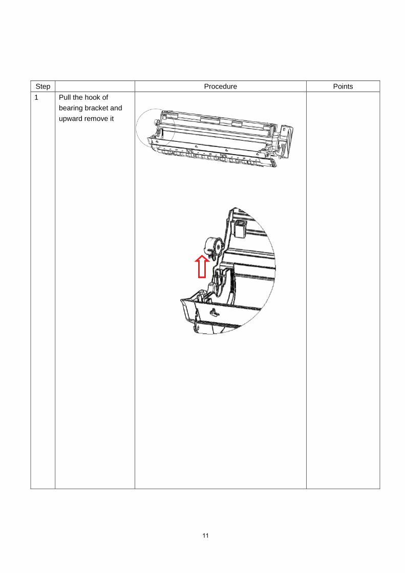
Step Procedure Points1 Pull the hook of
bearing bracket andupward remove it