service manual folding machine fk-4.400s … 4.400s-service manual.pdf · power consumption 1,8 kw...
TRANSCRIPT

FABRYKA
MASZYN
INTROLIGATORSKICH
[email protected] 90-019 Łódź, Poland, ul. Dowborczyków 12
www.introma.com.pl Adres do korespondencji i wjazd:
(Correspondence and delivery address:)
90-042 Łódź, ul. Targowa 11
Biuro handlowe – tel. 048-42-636-60-58
fax. 048-42-633-80-01
Serwis tel. 048-42-674-66-21
SERVICE MANUAL
FOLDING MACHINE FK-4.400S
WITH SUCTION FEEDER
Serial Number: ..........................
Year of Manufacture: ..........................

2
1. TRANSPORT AND STORAGE
1.1. Delivered condition
1.1.1. List of disassembled parts
1.1.2. List of equipment
1.1.3. Temporary protective layer
1.1.4. Conditions of storage
1.1.5. Packing
2. TECHNICAL DESCRIPTION
2.1. Application
2.2. Basic parameters
2.3. Folding principle
2.4. Folding methods
2.5. Folding capacity
3. ANALYSIS OF HAZARDS AND PROTECTION MEASURES APPLIED
3.1. Hazards
3.1.1. Mechanical hazards
3.1.2. Electrical hazards
3.2. Protective measures against mechanical hazards
3.3. Protective measures against electrical hazards
3.4. Conformity with safety standards
3.4.1. European standards
3.4.2. Polish standards
3.5. Principles of operating safety
4. PRE-ACTIVATION PREPARATIONS
4.1. Unpacking and assembly
4.2. Assembly of the folding machine
4.3. Checking the correctness of assembly
5. PRINCIPLES OF FOLDING MACHINE OPERATION
5.1. Mechanical part
5.2. Electrical part
5.3. Installation air
6. ADJUSTMENTS
6.1. Adjusting the selector mechanism
6.2. Setting the margins

3
6.3. Setting the blow-in nozzles
6.4. Setting the plates
6.5. Setting the gaps between rollers
6.6. Setting the paper clamp
6.7. Test manual folding
7. AUTOMATIC FOLDING
8. SCORING, PERFORATING, AND SLITTING
9. FOLDING DEFECTS, CAUSES, AND SOLUTIONS
10. MAINTENANCE
11. CONTROL PANEL
12. DRAWINGS
13. ELECTRICAL WIRING DIAGRAM

4
1. TRANSPORT AND STORAGE
1.1. Delivered condition
The FK-400S folding machine with suction feeder is delivered partly disassembled for transport.
The disassembled parts and equipment of the folding machine are as listed in points 1.1.1. and
1.1.2. below.
1.1.1. List of disassembled parts
Markings in accordance with Figure 2.
a) Feeding table (9)
b) Receiving conveyor (3)
c) Paper clamp (5)
d) Plate (7a),(7b), (8a) ,(8b)
e) Base of folding machine (1)
f) Compressor (21)
g) Compressor hose (15) (16) (17)
h) Delivering table mini (option)
1.1.2. List of equipment
a) Open ended spanner 6 / 7
b) Open ended spanner 8 / 10
c) Open ended spanner 13 / 17
d) Socket wrench 2
e) Socket wrench 3
f) Socket wrench 4
g) Socket wrench 6
h) Scoring unit
i) Perforating unit
j) Slitting unit
k) Service manual
l) Star-shaped screwdriver T20
m) Star-shaped screwdriver T25
1.1.3. Temporary protective layer
The folding machine is protected against corrosion for transport and storage. The durability of the
applied temporary protective layer is 3 months under specific conditions of storage.
1.1.4. Conditions of storage
The packed folding machine should be stored in a dry room, secured against atmospheric influ-
ences. During storage it is necessary to place the machine in accordance with the markings on the
packing and also avoid piling up pickings.

5
1.1.5. Packing
The packing of the folding machine consists of one cardboard boxes. These may be safely lifted
and moved using a fork-lift truck. During transportation of the boxes it is necessary to keep the
machine in an upright position, i.e. in accordance with the markings on the packing - the boxes
should not be turned, thrown, or dropped. The gross weight of the packed folding machine with
suction feeder equals 180 kg. The external dimensions of the cardboard boxes are 950 x 600 x
1000 mm each.
2. TECHNICAL DESCRIPTION
2.1. Application
The FK-4.400 folding machine with suction feeder is designed for folding sheets of paper by mak-
ing two folds. It may also be used for scoring, perforating and slitting sheets of paper.
2.2. Basic parameters
Folding capacity 30000 sheets/h
Maximum sheet size 37 x 70 cm
Minimum sheet size 9 x 9 cm
Maximum folding length 38 cm
Minimum folding length 4 cm
Minimal folding length for the special cassette* 2,5 cm
Paper basis weight* 60 - 180 g/m2
Compressor capacity 40m3/h
Positive/negative gauge pressure magnitude 0,5 bar
Supply voltage 230 V
Current frequency 50 Hz
Control voltage 24 V
Power consumption 1,8 kW
Weight of folding machine approximately 180 kg
External dimensions 150 x 130 x 60 cm
* Given parameters may vary depending on the type of fly and paperweight.
2.3. Folding principle
Description in accordance with Figure 1.
A separate sheet of paper is fed between feeding rollers 1,2 into cassette 1, until it reaches the
fender. Next, the sheet is bent in the room between the rollers and conveyed by the folding rollers
2,3. This is the first folding of the sheet. Rollers 2,3 feed the sheet with its folded edge into the cas-
sette until it reaches the fender. The sheer conveyed by the rollers is bent again in the room be-
tween the rollers and by the folding rollers 3,4. This is the second folding of the sheet. Similar op-
erations are performed using rollers 4,5 and 5,6. Folded sheet is received by the receiving rollers

6
7,8. These rollers can be equipped with scoring, perforating or cutting units. By adjusting fenders
inside the cassette it is possible to have various sorts of folding.
2.4. Folding methods
In order to have various sorts of folding, one needs to set the fenders in their proper places inside
the cassette, using the graduations marked on a cassette or to mount the stator. Table below
presents settings for various sorts of folding. In columns 1,2,3,4 the length of the fender in its cas-
sette is given. In columns A, B, C, D, E given the number of stripes of the folded paper, which
should be placed in proper slots which control the clearance between the rollers.
Types of folding 1 2 3 4 A B C D E
1/2
0
0
0
1
2
2
2
2
1/2
1/4
0
0
1
2
4
4
4
1/3
2/3
0
1/3
1/3
0
0
0
1
1
1
1
1
3
3
3
3
3
1/4
1/4
1/4
0
1
1
1
4
4
1/5
1/5
1/5
1/5
1
1
1
1
5
3/4
1/4
0
1/4
1
1
3
1
4
1/2
1/6
0
1/6
1
2
2
2
6

7
1/3
1/3
0
0
1
1
3
3
3
Table No. 1. Types of folding.
2.5. Folding capacity
The actual folding capacity is dependent above all on the format of the paper sheets, but also on
the basis weight and type of paper used. Capacity will also be influenced by the ambient humidity
and qualifications of operators and service personnel. The folding capacity given in point 2.2. is an
approximate value only.
3. ANALYSIS OF HAZARDS AND PROTECTION MEASURES APPLIED
3.1. Hazards
The potential hazards resulting from the construction and operation of the folding machine with
suction feeder are of a mechanical and electrical nature.
3.1.1. Mechanical hazards
Mechanical hazards may be caused by:
a) Sharp edges, corners and ends of elements, and also by their uneven and rough surfaces.
b) Moving parts of the drive and remaining mechanisms.
3.1.2. Electrical hazards
Coming into contact with active elements, i.e. with live elements constituting a threat of direct or
indirect electric shock.
3.2. Protective measures against mechanical hazards
a) The hazards referred to in point 3.1.1.a above have been eliminated by the rounding off or
smoothing of all accessible potentially hazardous edges and corners, and also by the appropri-
ate machining of surfaces in order to ensure their smoothness.
b) The hazards referred to in point 3.1.1.b above have been eliminated by the application of ap-
propriate guards.
3.3. Protective measures against electrical hazards
a) Application of a safe control voltage.
b) Location of control and supply equipment in casings.

8
3.4. Conformity with safety standards
The constructional solutions of elements and mechanisms applied in the folding machine, and also
the technical protective measures introduced to safeguard the operator against mechanical and
electrical hazards meet the requirements set forward in the standards referred to in points 3.4.1.
and 3.4.2. below.
3.4.1. European standards
- EN 292-1:1991 Safety of machinery - Part 1: Basic terminology, methodology
- EN 292-2: 1991 Safety of machinery - Part 2: Technical principles and specifications
- EN 294:1992 Safety of machinery - Safety distances to prevent danger zones being reached by
the upper limbs
- EN 953:1992 Safety of machinery. General requirements for the design and construction of
guards (fixed, movable)
- EN 60204-1:1992 Safety of machinery - Electrical equipment of machines. Part 1: General re-
quirements
3.4.2. Polish standards
- PN-83/M-08200 Work protection. Production machines and equipment. General safety require-
ments.
- PN-83/M-82001 Work protection. Mechanical guards for machines and equipment. General re-
quirements.
3.5. Principles of operating safety
During the execution of service-related operations, which include the use of the corner rounding
machine, the interchange of tools, maintenance, and repairs, it is necessary to observe the follow-
ing safety principles:
a) The operator of the folding machine and persons entrusted with its maintenance and repair
should be familiar with the construction, operation and technological potential of the machine.
b) Inspections, maintenance and repairs are to carried out solely by duly authorised persons hav-
ing the required qualifications.
c) All operations connected with the setting of the folding machine, interchanging tools, and carry-
ing out maintenance and repair-work may be carried out only after the power supply is
switched off.
d) The operator should start work only after having first checked whether all of the guards are in
place.
e) If any irregularities are observed in the functioning of the folding machine, the operator should
interrupt work and eliminate the defect (if he/she is duly qualified and authorised) or report the
irregularity.
f) Once work is finished, the power supply should be switched off.

9
4. PRE-ACTIVATION PREPARATIONS
4.1. Unpacking and assembly
The folding machine with suction feeder is delivered to the customer partly disassembled in card-
board boxes. The customer should take all of the elements of the machine out of these boxes, un-
wrap them from the protective foil sheets, and check the completeness of the delivery against the
list given in the service manual.
4.2. Assembly of the folding machine
The elements of the folding machine which have been disassembled for transport should be as-
sembled onto the folding machine in accordance with Figure 2. To this the end it is necessary to
carry out the following operations:
The components of the folding machine which have been uninstalled for transport should be reins-
talled as illustrated in Figure 2. Proceed as follows:
a) Place the base (1) of the folding machine on a level floor at the planned place of operation of
the machine.
b) Put the body (2) of the machine on the base (1). Fix it with four long screws M8 (22).
c) Install the conveyor (3) between the sidewalls of the body by placing the cutouts of the
conveyor on appropriate pins. Make sure that the conveyor dog (4) is properly engaged with
the drive cam.
d) Install the paper clamp.
e) Install the upper cassette (7) between the sidewalls of the body (2) by placing the cutouts of the
cassette on appropriate pins.
f) Install the lower cassette (8) in a similar way.
g) Install the feed table (9) between the sidewalls of the body (2) by placing the cutouts of the
table on appropriate pins. Make sure that the feed table gears are properly engaged with the
body gears.
h) Install two air-blast hoses (15) between the side margin stubs (12) and the distributor (19)
located below the feed table. Connect the suction hose (16) with the outflow stub (20) of the
valve, and the inflow stub of the valve with the suction cylinder stub (18).
i) Connect the electric cable of the compressor to the socket located on the wall below the
collector table.
4.3. Checking the correctness of assembly
In order to check whether the folding machine has been properly assembled, it is necessary to
carry out the following operations:
a) Turn the knob located on the right side of the folding machine. Turning should be smooth, light,
and jam-free. The flat belts of the feeding table should move uniformly, while the flat belts of

10
the receiving conveyor ought to execute a stepwise movement. The plate ends should not rub
against the folding rollers. The plates should be firmly placed upon the pivots and cannot have
any play.
b) Once the folding machine is connected to the supply network, switch on the compressor with
the switch-key (14). The four nozzles located on the feeding table should blow out air, while air
should be drawn in through the openings in the suction drum. If this is not the case, it is neces-
sary to change the hoses connecting the compressor with the feeding table.
5. PRINCIPLES OF FOLDING MACHINE OPERATION
5.1. Mechanical part
Description of principles of folding machine operation in accordance with Figure 3.
The stack of paper to be folded is placed between the margins (air strips) (2) on the feeding table
(1). This stack is then blown apart by the air issuing from the margins. The lowermost sheet is
sucked to the suction drum (4). The suction drum turns, takes this sheet, and passes it beneath the
lock (5) of the selector mechanism between the margins (6). In order to ensure the uniform single
collection of sheets, it is necessary to appropriately adjust the selector mechanism. The movable
flat belts in the front part of the feeding table move the sheet of paper between the folding rollers,
and then to the plates (9), where the folding process takes place. The plates are fitted with adjust-
able bumping blocks, which make it possible to choose one of a number of different folding meth-
ods. The folded sheet is transferred by the receiving rollers to the receiving conveyor (17).
The compressor, which generates positive gauge pressure in the side blow strips and the negative
gauge pressure in the suction cylinder, is mounted on the base (19). Mechanisms of the folding
machine are driven by an AC motor. The drive is transmitted from the motor to the mechanisms by
means of flat belts.
5.2. Electrical part
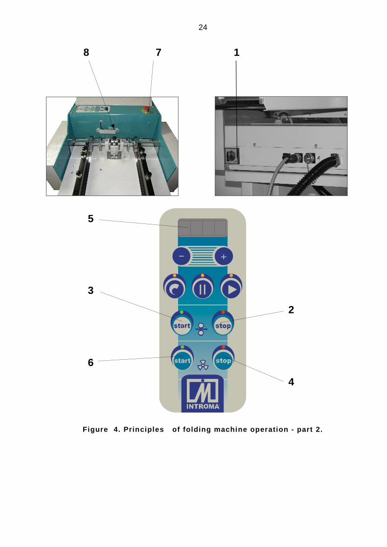
Description of principles of folding machine operation in accordance with Figure 4.
The main switch (1) supplies power to the machine. Pushbutton (3) starts the drive motor, while
pushbutton (2) stops it. See section 11.2 to adjust the drive motor speed, and therefore the operat-
ing speed. The machine is equipped with a sheet counter, which counts the number of folded
sheets, the number of sheets in a series, the time interval between series and displays the last
count of completed flies.
The counter cooperates with an optoelectronic sensor (8), which records the event of passing of a
sheet. If indications of the sensor are wrong, it needs to be programmed using the button on the
side wall of the sensor in the following way:
- First pressing and holding the button switches on the green, yellow and red diodes succes-sively, and then switches on all diodes.
- After second pressing, the green diode flashes for about 3 seconds and then it goes off. Now, the sensor is programmed.

11
5.3. Pneumatic system
Air is supplied to the system by compressor of capacity 40 m3/h. The blowing stub is connected to
the blow distributor mounted underneath the feed table with a hose. The air from the distributor is
delivered to the air strips through two hoses. On the strips there are valves that control the outflow
of air. The flowing-out air blows loose the paper sheet stack. The suction stub is connected to the
suction cylinder by an electric valve. Paper sheets are sucked to the cylinder and fed to the folding
rollers.
6. ADJUSTMENTS
6.1. Adjusting the selector mechanism
Description of selector mechanism adjustment in accordance with Figure 5.
The role of the selector mechanism is to collect one sheet of paper from the stack. In order to set
the selector mechanism, it is necessary to carry out the following operations:
a) Using the handwheel (1) set the lock relative to the suction drum (3). For thick paper the lock
should be located above the axis of the suction drum. For thin paper the lock should be moved
back by approximately 4 - 6 mm.
b) Using the handwheel (4), adjust the gap between the lock (2) and the suction drum (3). For
thick paper the gap should be adjusted to the thickness of the paper. For thin paper the gap
should be adjusted to 4-6 times the thickness of the paper.
c) Using the lever (5), set the suction nozzle located inside the suction drum to the appropriate
position. The nozzle should be directed towards the front edge of the lock (2).
6.2. Setting the margins
Description of setting in accordance with Figure 3.
The feed table of the folding machine (1) is equipped with two side margins (air strips). They are
used to set up the stack of paper sheets to be folded. The margins have to be set symmetrically to
the axis of the machine using knobs (3). The margins should be parallel to the axis of the machine.
The clearance between a sheet of paper and the margins should be less than 1 mm. But if it is too
small, collecting the sheets may be difficult. Incorrect setting of margins may be a possible reason
for the creasing being not perpendicular to the edge of a sheet. If this is the case, slightly adjust
the angular position of the margins making sure that they remain parallel. You can do it by turning
the knob (21) in a proper direction.
6.3 Setting the blow
Description below refers to Figure 3.
To facilitate collecting sheets from the bottom of a stack, the stack should be loosened by air blow-
ing from the margins (2). Depending on the size of a sheet to be folded, close the air outlets that

12
are beyond the stack using knobs (7). If the blowing is set up correctly, the stack of sheets will free-
ly float upon an air cushion.
6.4 Setting the plates
Description of setting in accordance with Figure 3.
The folding machine is equipped with two plates (9). By appropriately setting the bumping blocks
(12) within the plates, it is possible to achieve the desired types of folding. For positioning of bump-
ing blocks, see Table No. 1. In order to move the bumping block within the plate, it is necessary to
loosen the knob (10) and slide the bumping block along the guide. The knob (14) serves to fine-
tune the setting of the bumping block. While moving the bumping block it is recommended to use
the scales located on the plate. Data given by the scales are general reference only, and their va-
lidity will be influenced by the basis weight of the folded paper. The sheet of paper which slides into
the plate should hit the bumping block along its entire width. It this is not the case, it is necessary
to adjust the setting angle of the bumping block by loosening the knob (11) and turning the nearby
knob (13). If a sheet of paper cannot enter the upper cassette while folding (a single creasing only
is to be made – see table 1), remove the cassette from the machine and insert a stator. Proceed in
a similar way with the lower cassette. Each time a cassette or a stator is replaced it is necessary to
check the cassettes for correct assembly by manually turning the machine with the hand-wheel.
The gap nozzle of the cassette may not abrade the folding rollers while turning the machine.
NOTE:
If the last folding is to be shorter than 4 cm., the last cassette should be equipped with a special
insert. The insert is inserted from the front side of the cassette into the slot for the paper and
mounted using special holds to its margins. The insert should be pressed against the bottom of the
slot with four screws tipped with balls.
6.5 Setting the gaps between rollers
Description refers to figure 1.
In order to assure the high quality of folding, the clearance between the rollers should be adjusted
properly. The rule of thumb is that the clearance should be equal to the width of the inserted paper,
taking into account folding between the rollers. To satisfy this condition, place stripes of paper into
clearance regulators, and then fold the desired amount of it. There should be equal number of
stripes at both sides of the machine in matching regulators.
The number of stripes that should be placed in regulators for different kinds of inserts is given in
table 1.
6.6 Setting the paper clamp
Description of setting in accordance with Figure 3.
The role of the paper clamp (17) consists in ensuring the orderly arrangement of the folded sheets
of paper on the receiving conveyor. To achieve this it is necessary to loosen the knob (18) and

13
place the clamp at the appropriate distance from the receiving rollers. The folded sheets of paper
should fall out of the receiving rollers directly under the clamp wheels, and then be transported in
an orderly manner on the conveyor.
6.7 Test manual folding
Description of operations in accordance with Figure 3. Having carried out the initial settings in ac-
cordance with points 6.1, 6.2, 6.3, 6.4 and 6.5. above, it is necessary to proceed to test manual
folding. Place one sheet of paper of the type to be folded between the margins (2), pass it manu-
ally under the lock (5), and then execute a complete folding cycle by turning the handwheel. During
folding it is necessary to observe the sheet, its passage between the margins, and check whether
the edges of the sheet come into contact with the bumping blocks within the plates. After inspect-
ing the folded sheet, adjust settings if required.
Note:
The regulatory settings described in point 6 are general reference only. When activating and oper-
ating the machine, these should be adjusted depending on the type and humidity of the paper. The
quality of the end-product will also be influenced by the ambient humidity and temperature.
7. AUTOMATIC FOLDING
Description below refers to Figure 4.
To start the automatic folding of paper sheets, proceed as follows:
a) Carry out all settings as described in section 6
b) Put a stack of paper in between the margins, after having it fanned and aerated, and press it
against the lock.
c) Start the compressor using switch (6)
d) Start the folding machine using the green pushbutton (3)
e) Feed in the control sheet of paper according to 11.4
f) Start the continuous operation of the machine according to 11.5
g) For emergency stop of the machine, use switch (7)
h) In case of any abnormal operation, stop the machine with pushbutton (2) and switch off the
compressor using pushbutton (4).
8. SCORING, PERFORATING, AND SLITTING
Apart from folding, the folding machine may be used to perform additional operations, such as
scoring, perforating, and slitting.
In order to carry out any one of the abovementioned operations, it is necessary to carry out the
following operations in accordance with Figure 6:
a) Remove the side guard on the knob side by unscrewing the four knobs which fasten the guard.

14
b) Using socket wrench 4 (delivered as standard machine equipment), unscrew the bearing
sleeves (1), (2).
c) Pull the receiving rollers (3), (4) out of the folding machine.
d) Using socket wrench 2 (delivered as standard machine equipment), loosen the three screws
which lock the sleeves (5), (6) in place, and slide these sleeves off the rollers.
e) Fit the receiving rollers with the appropriate elements in accordance with the drawing.
f) Install the sleeves (5), (6) onto the receiving rollers.
g) Reinstall the receiving rollers (3), (4), paying attention to the markings of rollers 1, 2.
h) Screw in the bearing sleeves (1), (2), paying attention to the markings of sleeves 1, 2 and the
markings on the housing (7). Before screwing in the sleeves, pour two drops of machine oil into
each of the bearing bushings.
i) Reinstall the side guard
9. FOLDING DEFECTS, CAUSES, AND SOLUTIONS
No. Symptoms Causes Solutions
1. Sheets of paper are
not collected from the
feeding table
- humid paper - dry the paper
- incorrect setting of blow-in noz-
zles
- set the nozzles in accor-
dance with point 6.3. above
- insufficient air blow-in - increase air blow-in in ac-
cordance with point 7 above
- stack of sheets of paper is too
high
- remove excess paper from
the stack
- incorrect setting of selector
mechanism
- set the selector mechanism
in accordance with point 6.1.
above
- high margins brought too close
together
- set the margins in accor-
dance with point 6.2. above
2. Sheets are not folded
in parallel
- incorrect setting of low margins - set the margins in accor-
dance with point 6.2. above
- incorrect setting of the angle of
the bumping block within the
plate
- set the bumping block within
the plate in accordance with
point 6.4. above
- badly-cut sheets of paper - adjust the cutting of paper
sheets
3. Folded sheets are
improperly arranged
on the receiving con-
veyor
- incorrect setting of paper clamp - set the clamp in accordance
with point 6.5. above

15
10. MAINTENANCE
No. Operations Agents Frequency
1. Cleaning and tidying the work station daily
2. Washing the folding and receiving roll-
ers
extraction naphtha daily
3. Greasing the bearing bushings of the
receiving rollers
machine oil weekly
4. Changing the compressor filters yearly
11. CONTROL PANEL
11.1. Control desktop
Description below refers to Figure 7.
Having switched on the machine using the main switch, symbols ‘1111’, ‘2222’, ‘3333’, … , ‘9999’
will consecutively appear on the display (1), which means that the machine is testing its program in
the driver.
Next, you may see on a display:
- digit ‘0’, when the sheet counter had been reset before the machine was switched off, OR
- a number (e.g. ‘1234’), if the last count of flies had been stored in the memory
11.1.1 Saving the count of completed flies
In order to save the number of completed flies press and hold button (3) until the word ‘save’ ap-
pears on the display (1). It means that the last count of flies has been stored in the memory.
11.1.2 Resetting the sheet counter
In order to reset the sheet counter press and hold button (2) until you hear a sound and digit ‘0’
appears on the display.
11.2 Changing the machine operation settings
Descriptions below refer to Figure 7.
11.2.1 Changing the speed of folding rollers
In order to reduce the rotary speed of folding rollers:
- press button (4) to change the speed of folding rollers – it is signaled by switching the
button light on and displaying the note, e.g.:
F 5

16
Where:
F – denotes the speed mode
5 – last stored value of folding rollers speed, expressed as percent of the maximum speed (in this
example it is 5 % of maximum speed).
- reduce the speed of folding rollers by pressing button (2) (changes 5 units at once)
- save new settings by pressing button (4) again and hold it until the word ‘save’ appears on
the display (1).
In order to increase the rotary speed of folding rollers:
- press button (4) to change the speed of folding rollers – it is signaled by switching the
button light on and displaying the note, see above.
- increase the speed of folding rollers by pressing button (3) (changes 5 units at once)
- save new settings by pressing button (4) again and hold it until the word ‘save’ appears on
the display (1).
11.2.2. Changing values of air blow parameters
To turn the compressor ON press pushbutton (9). To turn it OFF, press pushbutton (10). You may
change the magnitude of air suction or blowing by turning appropriate knobs mounted on the com-
pressor.
11.2.3. Programming the length of a series
To program the numbers of sheets in the series:
- press button (6). You will see on the display
Where:
C – denotes the numbers of sheets in the series mode
0 – the actual numbers of sheets in the series
- change the number of sheets in the series by pressing buttons (2) or (3). Short pressing
causes the number to change by 5 units, while pressing and holding causes the numbers of
sheets in the series to change by 50 units.
- To save the set numbers of the sheets, press button (6), until the word ‘save’ appears on
the display.
11.3 Programming a time interval between series
Description below refers to Figure 7.
In order to program the time interval between series:
C 0

17
- press button (5). You will see on the display
Where:
P – denotes the time interval mode
0 – the actual time interval
- change the time interval between series by pressing buttons (2) or (3). The minimum
interval is 1 s, the maximum interval is 30 s.
- To save the set time interval between series, press button (5), until the word ‘save’ appears
on the display.
11.4 Feeding a single control sheet
Description below refers to Figure 7.
Each time a setting for a particular type of fly is made, it is necessary to check whether the ma-
chine produces the fly properly. The machine facilitates this task through an option of feeding a
single sheet. Proceed as follows:
- turn the compressor ON using button (9)
- shortly press button (7) so to feed a single sheet
Note:
The sheet is fed to the machine with a small delay.
11.5 Continuous operation mode
Having set all parameters of the machine and checked if the control fly is valid, start the machine
for operation in the continuous mode. Proceed as follows:
- turn the compressor ON using button (9) – it is signaled by displaying the note:
- press and hold button (7) – it is signaled by displaying the note
The machine starts the automatic feeding of paper after about 2 seconds
11.6 Stopping the machine
- To stop the machine, press button (8). You will see on the display:
- To turn the compressor OFF, press button (10). You will see on the display:
P 0
C o n
U o n
U o f f

18
11.7 Entering the number of folded sheets.
Description refers to figure 7.
In order to read from the display (1) how many thousands sheets have been folded, press simulta-
neously buttons (8) and (10) on the control panel. The readout lasts for 5 seconds.
C o F F

19
12. DRAWINGS
1
2 3
4 5
6
7
8
1
3
2
4
A
B
C
D
E F
Figure 1. Folding principle.

20
Figure 2. Assembly of the folding machine.
/ to be fo l lowed on the next page /
2
16
8
22
1
4
7
5
3
17
21
6

21
- +
15 12 9 14
18 19 20

22
Figure 3. Principles of folding machine operation - part 1.
9
18
16
17
20
19
1
22
9
3 5 4 3 2
6 21 7

23
Figure 3. Principles of folding machine operation - part 2.
10 11 12
15 14 13
24
- +
Figure 4. Principles of folding machine operation - part 2.
8 7 1
5
3
6
2
4

25
Figure 5. Selector mechanism adjustment.

26
Figure 6. Scoring, perforating, slitting.
1 2 7 3 4
5
6

27
- +
1 Display
2 Reduction of machine settings
3 Increase of machine settings
4 Change of folding rollers rotary speed
5 Set pause time between series
6 Set a long serie
7 Turning ON folding rollers
8 Turning OFF folding rollers
9 Turning ON the compressor
10 Turning OFF the compressor
F i g u r e 7

28
1 3 . E L E C T R I C A L W I R I N G D I A G R A M
SUCK TRIG
SYNC-
O1
MOC3020
R5 220
R91k
+12
12
JP6
R8 220
12
JP7
BLOW
SUCKR3
1k
MT- BLOW
MT- SUCK
GATE SUCK
GATE BLOW
R6 220
R7 220
BLOW TRIG
O2
MOC3020
R111k
+12
R4
1k
COMPR. ON/OFF
12
JP5
CO
MP
RE
SS
OR
SUCK TRIG
SYNC-
SYNC+BLOW TRIG
COMPRESSOR
R1
100k R2
1k
+12
COMPRESSOR
D61N4148
COMPRESSOR
11
22
33
44
55
K2
RELAY-SPDT
+12
123
JP10
+CE1
220uF/25VC5100n
11
22
33
44
TR2
TMD2 220/9V
C1
10n (Y)
C2
10n (Y)
C4
100nF (X2)
Class Y
Class X2
RV1S14K275EARTH
D7
1N4148D9
1N4148
D8
1N4148D11
1N4148
N
L
COMPRESSOR
COMPRESSOR ON/OFFT2
BC557
COMPRESSOR
R10
100k
R13
1k
T1BC847
C3
100n
+12
R12100k
COMPRESSOR
F16,3A D1
1N4148
1234567
JP8
HEADER 7
T3BTA140-800
O3
MOC3021
R15
22012
JP1
N
L_F
R16220
R14
150/1W
C6
100n/250V (Y)
VCC R18
1k
R20
330
R17
10k/0.5W
RV2S14K300
VALVE ON/OFF
L_F
D21N4148

29
VC
C
+
C11
1uT
SY
NC
SY
NC
SU
CK
BLO
W
C3
100n
C4
100n
GN
DG
ND
BU
Z2
CFG
06
EA
/VP
31
X1
19
X2
18
RE
SE
T9
P3.
7/R
D17
P3.
6/W
R16
P3.
2/IN
T0
12P
3.3/
INT
113
P3.
4/T
014
P3.
5/T
115
P10
1
P11
2
P12
3
P13
4
P14
5
P15
6
P16
7
P17
8
AD
0/P
0039
AD
1/P
0138
AD
2/P
0237
AD
3/P
0336
AD
4/P
0435
AD
5/P
0534
AD
6P06
33
AD
7/P
0732
A8/
P20
21
A9/
P21
22
A10
/P22
23
A11
/P23
24
A12
/P24
25
A13
/P25
26
A14
/P26
27
A15
/P27
28
PS
EN
29A
LE/P
30P
3.1/
TxD
11P
3.0/
RxD
10
U7
AT
89C
2452
X2
24M
Hz
C9
33p
C10
33p
GN
D
GN
D
VC
C
1 2 3
JP5
Photo det.
R44
10k
T6
BC
557 R91
10k
R67
100k
VC
C
GN
D
VC
C1 2 3 4 5 6 7 8 9 10 11 12 13 14 15
J2 CO
N15
RO
W1
RO
W2
RO
W3
CO
L1C
OL2
LED
2
CO
L3
ab c
def
g
h
ED
WA1CH
GFWA2AB
LED
1a
b cd
efg
h
ED
WA1CH
GFWA2AB
LED
3
T7
BC
557
T9
BC
557
T11
BC
557
R82
10k
R81
10k
R80
10k
8x22
0R
R68
100k
R69
100k
R70
100k
ab c
def
g
h
ED
WA1CH
GFWA2AB
LED
2
VC
C
R93 R94
R95
R96
R97
R98
R99
R10
7
AN
OD
A0
AN
OD
A1
AN
OD
A2
LED
_A
LED
_B
LED
_C
LED
_D
LED
_E
LED
_F
LED
_G
LED
_H
ab c
def
g
h
ED
WA1CH
GFWA2AB
LED
8
T12
BC
557
R83
10k
R71
100k
AN
OD
A3
LED
1
GN
D
T4
BC
557
GN
D
+24V
IN
R53
100k
R90
10k
R89
10k
VC
C
PR
E1
M/W
C7
E1
2
E2
3
SC
L6
SD
A5
U8
ST
24C
02
EE
_CLK
EE
_DA
TA
VC
C
VC
CV
CC
C2
100n G
ND
VC
C
+C
T3
1uTV
CC
GN
D
GN
D
CO
MP
5T
CA
P3
IPK
7
IDC
8
ISW
C1
ISW
E2
VCC6
GND4
U11
MC
3406
3AD
D4
1N58
19
GN
D
L2
220u
H
R11
6
2R2
+C
E6
100u
/35V
C15
330p
GN
D
+C
T410
0uT/
10V G
ND
GN
D
R11
5
2R2
+C
T510
0uT/
10V
C14
100n
GN
DG
ND
VC
CR
118
3k3
R11
71k
1
GN
D
D6
BZX8
4/C
5V1
GN
D
R86
10k
R76
10k
R63
100k
R66
100k
GN
D
VS
DO
N/O
FF
PH
OT
O IM
P S
EP
BU
ZZE
R
R87
10kV
CC
PH
OT
O IM
P
1 2456
N11
CN
Y17
-4
R79
330
GN
DR
65 100k
CO
MP
RE
SS
OR
CO
MP
RE
SS
OR
GN
D
1 2456
N13
CN
Y17
-4
R85
330
GN
D
COMPRESSOR
R72 10
0k
CO
MP
RE
SS
OR
CO
MP
RE
SS
OR
SU
CK
TR
IG
R49
560
1 2456
N12
CN
Y17
-4
R50
560
R11
41k
R73
100k
GN
DG
ND
SY
NC
-S
YN
C+
R92
10k
VC
C
BLO
W T
RIG
VS
D S
PE
ED
CO
MP
RE
SS
OR
R75
10k
VSD
R52 1k
R54
100k
VS
D S
PE
ED
sep
1 2 3 4 5 6
JP4
VS
DC
OM
GN
D
GN
D
+5V
SD
+C
E5
4u7
+C
E4
4u7
VS
DC
OM
VS
DC
OMR51
1k
R74
100k
+5V
SD
OC
1C
LK11
1D2
2D3
3D4
4D5
5D6
6D7
7D8
8D9
1Q19
2Q18
3Q17
4Q16
5Q15
6Q14
7Q13
8Q12
U9
74H
C57
4
OC
1C
LK11
1D2
2D3
3D4
4D5
5D6
6D7
7D8
8D9
1Q19
2Q18
3Q17
4Q16
5Q15
6Q14
7Q13
8Q12
U10
74H
C57
4
7x33
0RR
100
R10
1R
102
R10
3R
104
R10
5R
106
GN
D
DA
TA
0D
AT
A1
DA
TA
2D
AT
A3
DA
TA
4D
AT
A5
DA
TA
6D
AT
A7
DA
TA
0D
AT
A1
DA
TA
2D
AT
A3
DA
TA
4D
AT
A5
DA
TA
6D
AT
A7
CLK
1C
LK2
CLK
2
RO
W1
RO
W2
RO
W3
CO
L1C
OL2
CO
L3
LED
3LE
D4
LED
5LE
D6
LED
7
CLK
1
VS
D S
PE
ED
VS
D O
N/O
FF
GN
D
+24V
IN
C13
100n
D1
1.5K
E27A
1 2456
N10
CN
Y17
-4
R78
560
VC
C
CO
MP
RE
SS
OR
CO
MP
R64
100kR88
10k
CO
MP
R. O
N/O
FF
R77
1k
R84
1k
SU
CK
BLO
W
VS
D O
N/O
FF
+24V
CO
MP
RE
SS
OR
R10
8R
109
R11
0R
111
R11
2R
113
GN
D
+24V
+C
T1
1uT
C1
100nV
CC
VC
C
GN
DG
ND
6x68
0R
R1
10k
C7
100nV
CC
GN
D
C6
100nV
CC
GN
D
C5
100nV
CC
GN
D
R7
10k
T3
BC
557
R4
100k
VC
C
R6
10k
T2
BC
557
R3
100k
VC
C
R5
10k
T1
BC
557
R2
100k
VC
C
C8
100nV
CC
GN
D
D2 1N
4148
D3
1N41
48
T5
BC
557
C12
10n
VS
DC
OM
VS
DC
OM
T8
BC
547
T13
BC
547
GN
D
C16
10n
GN
D
R8
330
T10
BC
547
D5
1N40
07
+24V
1 2 3 4 5 6 7
JP6
D7
BZX8
4/C
3V3
R9
1k
VC
C
R10
1k
VA
LVE
12
J1 JUM
PER
GN
D
1 2456
N1
CN
Y17
-4
R13
560
VC
C
CO
MP
RE
SS
OR
R12
100kR11
1k
CO
MP
RE
SS
OR
VA
LVE
VA
LVE
ON
/OFF
VA
LVE
ON
/OFF