service manual - janome dealersite / site pour …dealers.janome.nl/sites/default/files/sm...
TRANSCRIPT

SERVICE MANUAL
MC11000
MC 11000
CONTENTS
Changing External PartsFace and top covers ............................................................................................................................................. 1Belt cover .............................................................................................................................................................. 2Bed cover .............................................................................................................................................................. 3Base ...................................................................................................................................................................... 4Front cover ............................................................................................................................................................ 5Rear cover ............................................................................................................................................................ 6Thread tension unit ............................................................................................................................................... 7Thread cutter unit .................................................................................................................................................. 8Needle threader motor .....................................................................................................................................9-10
Wiring Diagram ........................................................................................................................................................ 11
Replacing:Printed Circuit Board A ....................................................................................................................................... 12Printed Circuit Boards F1, F2 and Slide volume ................................................................................................ 13Printed Circuit Board B ....................................................................................................................................... 14Switching Power Supply ..................................................................................................................................... 15DC Motor and Adjusting Motor Belt Tension ....................................................................................................... 16
Adjusting:Needle Drop Position .......................................................................................................................................... 17Hook Timing ........................................................................................................................................................ 18Needle bar height ............................................................................................................................................... 19Clearance between Needle and Hook ................................................................................................................ 20Backlash between Hook Drive Gear and Lower Shaft Gear .............................................................................. 21Presser Foot Position and Height ....................................................................................................................... 22Feed dog height .................................................................................................................................................. 23Height of Embroidery Foot P .............................................................................................................................. 24Shield Plate Position ........................................................................................................................................... 25Tension Release Mechanism.............................................................................................................................. 26Needle Thread Tension ....................................................................................................................................... 27
Replacing and Adjusting Threader plate.................................................................................................................. 28
Adjusting Needle Threader Switch .......................................................................................................................... 29
TTP Adjusting Mode ................................................................................................................................................ 30
Adjusting:Stretch Stitch Balance ........................................................................................................................................ 31Presser Foot Lifter Sensor .................................................................................................................................. 32Buttonhole Lever ................................................................................................................................................. 33Presser Foot Sensor ........................................................................................................................................... 34Remaining Bobbin Thread Sensor ..................................................................................................................... 35Thread Cutter Solenoid ...................................................................................................................................... 36Upper Shaft Clutch Solenoid .............................................................................................................................. 37Thread Cutter Switch .......................................................................................................................................... 38Bobbin Winder Stopper ...................................................................................................................................... 39Threader Drawing Lever ..................................................................................................................................... 40X and Y Sensors ................................................................................................................................................. 41Sewing Start Position ......................................................................................................................................... 42
Setting Position of Thread Take Up lever ................................................................................................................ 43
To Adjust:Upper Shaft Declutch Device ............................................................................................................................. 44
Setting Position of Parts on Lower Shaft ................................................................................................................. 45
Setting Position of Upper and Lower Shafts ............................................................................................................ 46

Changing External Parts (1)
To remove:
1 Remove the 2 screws (A) and remove the face cover
(1).
To attach:
2 Follow the above procedure in reverse.
Replacing the face cover
Replacing the top cover
To remove:
1. Open the face cover.
2. Remove the 2 caps (2) and their screws (B) and (C).
Raise the carrying handle (3) and remove the screw
(D).
3. Raise the top cover and disconnect the bobbin
winder connector (4). Remove the top cover sliding
towards the back.
Note: The pressure dial is removed with the top
cover.
To attach:
4. Raise the carrying handle and insert the top cover
guiding it in from the back.
5. Connect the bobbin winder connector to printed cir-
cuit board A.
6. Tighten the screws (B), (C) and (D).
7. Attach the caps.
(1)
(A)
(3)
(4)
(2) (2)
(B)(C)
(D)
1
MC 11000
Changing External Parts (2)
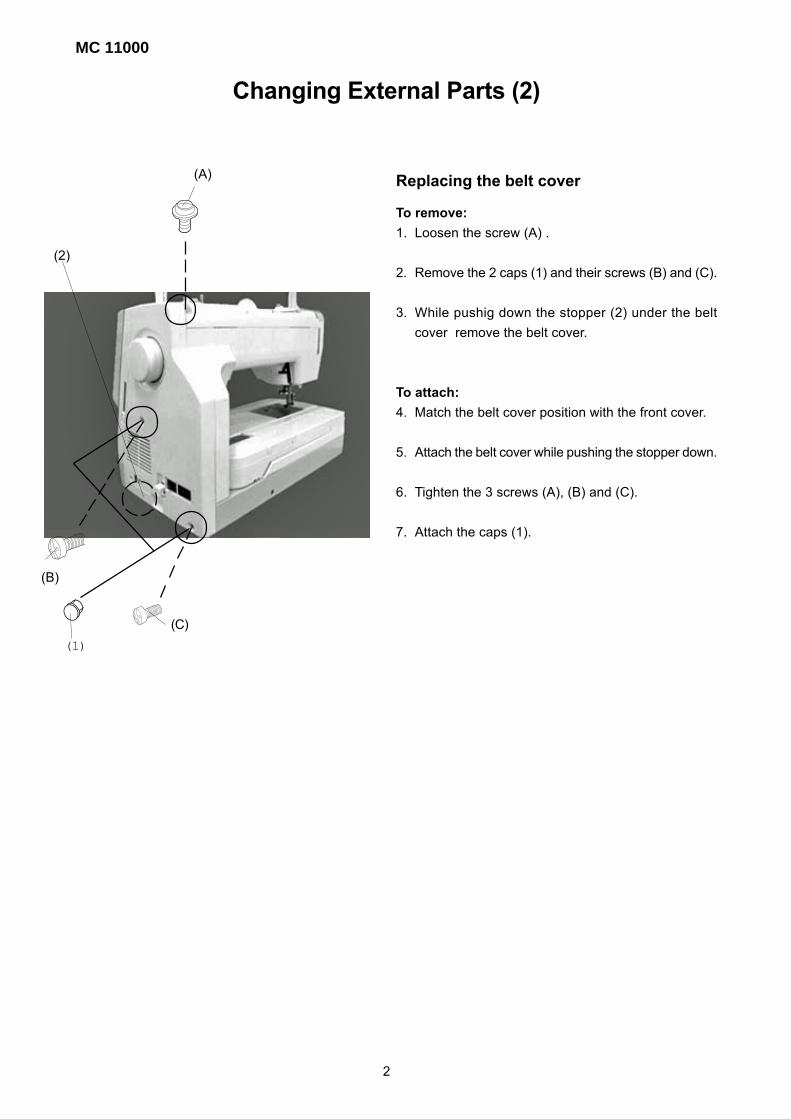
Replacing the belt cover
To remove:
1. Loosen the screw (A) .
2. Remove the 2 caps (1) and their screws (B) and (C).
3. While pushig down the stopper (2) under the belt
cover remove the belt cover.
To attach:
4. Match the belt cover position with the front cover.
5. Attach the belt cover while pushing the stopper down.
6. Tighten the 3 screws (A), (B) and (C).
7. Attach the caps (1).
(2)
(A)
(B)
(C)
(1)
2

Changing External Parts (3)
Replacing the bed cover
To remove:
1. Remove the extension table.
2. Remove the 2 screws (A) and remove the bed cover.
To attach:
3. Follow the above procedure in reverse.
(A)
3

MC 11000
Changing External Parts (4)
Replacing the base
To remove:
1. Remove the extension table.
2. Remove the belt cover.
3. Disconnect the connector (1) from printed circuit board
S1 (2).
4. Remove the screws (A) and (B) and remove the base.
When removing the base, push the machine body away
from you. (Do not pull the base toward you.)
To attach:
5. Tighten the 4 screws (A) and (B) slightly.
6. Attach the extension table.
7. Match the extension table, base and free arm position
and tighten the screw (B).
8. Tighten the remaining screws (A).
9. Insert the connector to the printed circuit board S1 from
opening between the releasing arm (3) and machine
body.
10. Attach the belt cover.
(1)(2)
(A) (A)
(A) (B)
(3)
4
(A)
(B)
(C)
(D)
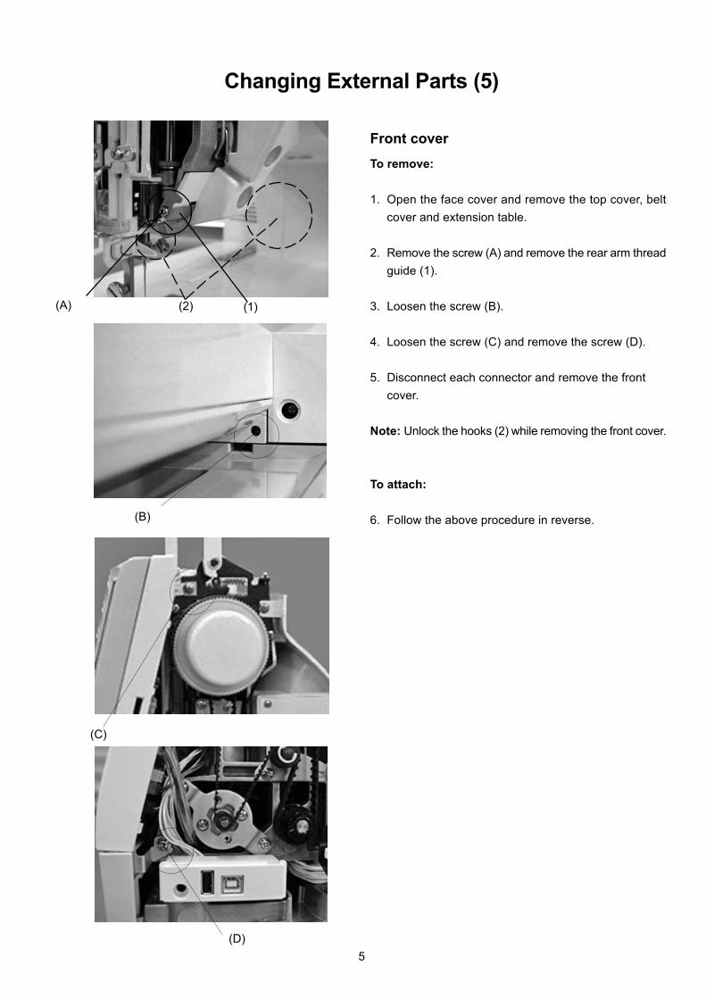
Changing External Parts (5)
To remove:
1. Open the face cover and remove the top cover, belt
cover and extension table.
2. Remove the screw (A) and remove the rear arm thread
guide (1).
3. Loosen the screw (B).
4. Loosen the screw (C) and remove the screw (D).
5. Disconnect each connector and remove the front
cover.
Note: Unlock the hooks (2) while removing the front cover.
To attach:
6. Follow the above procedure in reverse.
Front cover
(1)(2)
5
MC 11000
(A)
(B)
(C)
(D)
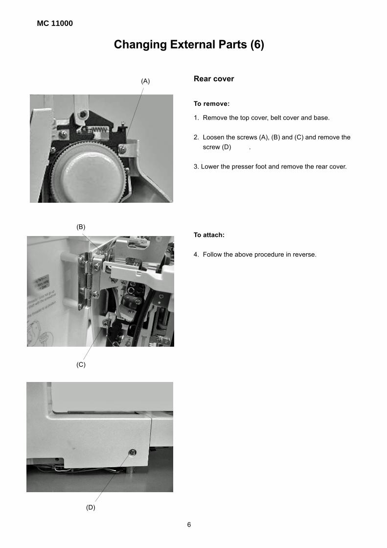
Changing External Parts (6)
1. Remove the top cover, belt cover and base.
2. Loosen the screws (A), (B) and (C) and remove the
screw (D) .
3. Lower the presser foot and remove the rear cover.
To attach:
4. Follow the above procedure in reverse.
Rear cover
To remove:
6

(A)
(B)
Changing Thread Tension Unit
To remove:
1. Remove the front cover.
2. Lower the presser foot.
3. Remove the screws (A) and (B).
4. Pull the connector out from the ìUî board and remove
the thread tension unit.
To attach:
3. Follow the above procedure in reverse.
Note: After changing the thread tension, make sure that
the tension release mechanism works correctly.
(See page 26)
7

MC 11000
1. Remove the needle plate and bed cover.
2. Loosen the screw (A) and remove the thread cutter
cover (1) .
3. Remove the 2 screws (B) and remove the thread cutter
unit.
4. Insert the pins (1) and (2) into the thread cutter hole and
attach the thread cutter unit with the screw (B).
Note: After changing the thread cutter unit, check that
the driving arm(4) is functioning properly by
turning the handwheel.
1. Lower the needle bar to its lowest position.
2. Push the driving arm (1) down and insert the
pin (3) into the groove of the cutter driving cam
(5).
3. Turn the handwheel to drive the cutter slide
plate.
4. When the sliding plate returns from the
rightmost position, the drawing arm (1) should
be released and return to the “UP” position.
(B)
(B)
(A)
Replacing the Thread Cutter unit
(1)
(1)
(3)
(4)
(5)
(1)
8
(2)
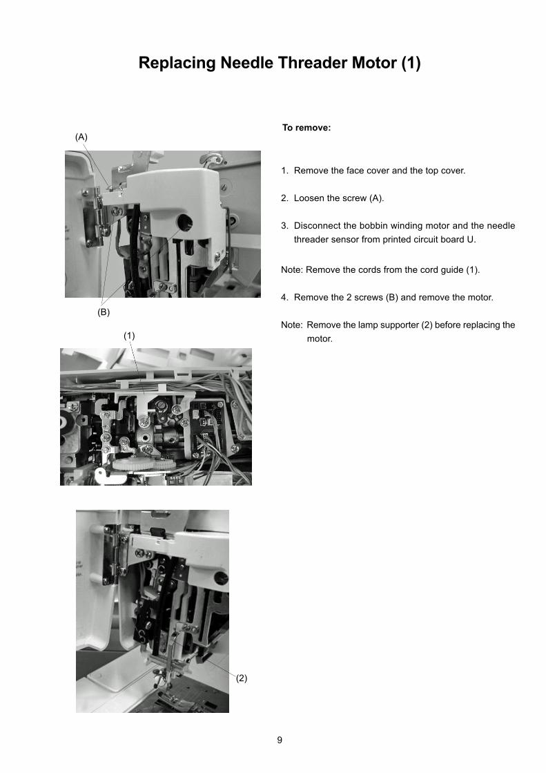
To remove:
1. Remove the face cover and the top cover.
2. Loosen the screw (A).
3. Disconnect the bobbin winding motor and the needle
threader sensor from printed circuit board U.
Note: Remove the cords from the cord guide (1).
4. Remove the 2 screws (B) and remove the motor.
Note: Remove the lamp supporter (2) before replacing the
motor.
(A)
(B)
Replacing Needle Threader Motor (1)
(1)
(2)
9

MC 11000
Replacing Needle Threader Motor (2)
To attach:
5. Insert the projection (1) of the needle bar supporter
into the corner part of the moval body (2).
6. Attach the motor (4).
7. Insert each cord into the cord guide (3) and connect
to printed circuit board U. Attach the front cover.
8. Attach the face cover and top cover.
(4)
(1)
(2)
(3)
10

Wiring Diagaram
Printed circuit board R (white)
(Since it is easy to break, remove
this part with extreme care.)
Bobbin winder (black)
Printed circuit board U
(black)
Printed circuit board L2 (gray)
Printed circuit board L2 (white)
Printed circuit board F1 (red)
Printed circuit board F2 (black)
Slide volume (red)
Printed circuit board B (black)
Printed circuit board U (black)
LCD Motor (top/bottom)
Printed circuit board P (black)
Printed circuit board Q (black)
Feed motor (red)
Printed circuit board S1 (black)
Presser foot lifter sensor (brown)
P foot sensor (blue)
Printed circuit board A (black)
Printed circuit board L3 (gray)
Printed circuit board A (black)
Needle threader motor (black)
Printed circuit board A
LCD detection switch (top
position)(blue)
LCD detection switch
(bottom position)(brown)
Switching regulator (white)
DC Motor (white)
Remaining bobbin thread
solenoid (black)
Thread cutter solenoid
(white)
Upper shaft disconnect
solenoid (red)
Potentiometer (blue) Needle threader motor detection
switch (bottom)(brown)
Needle threader motor
detection switch (top)(blue)
Buttonhole sensor (white)
Thread cutter sensor (black)
Printed circuit board UZigzag width motor (black)
Thread tension motor (gray)
11

MC 11000
(A)
(A)
Replacing Printed Circuit Board A
To remove:
1. Remove the front cover.
2. Disconnect each connector from printed circuit
board A.
3. Remove the 8 screws (A) and remove printed
circuit board A with the card guide (1).
To remove:
4. Follow the above procedure in reverse.
(1)
12

(A)
(B)
Replacing Printed Circuit Boards F1, F2 and Slide Volume
Printed circuit board F1
To remove:
1. Remove the front cover.
2. Pull out the connector from printed circuit board
A.
3. Remove the 2 screws (A) and remove printed cir-
cuit board F1 (1).
To attach:
4. Follow the above procedure in reverse.
Printed circuit board F2
To remove:
1. Remove the front cover.
2. Pull out the connector from printed circuit board
A.
3. Remove the 3 screws (B) and remove printed cir-
cuit board F2 (2).
To attach:
4. Follow the above procedure in reverse.
Slide volume
To remove:
1. Remove the front cover.
2. Pull out the slide volume connector from printed
circuit board A.
3. Remove the 2 CS rings (3) and remove the slide
volume (4).
To attach:
4. Follow the above procedure in reverse.
(1)
(2)
(3)(4)
13
MC 11000
(A)
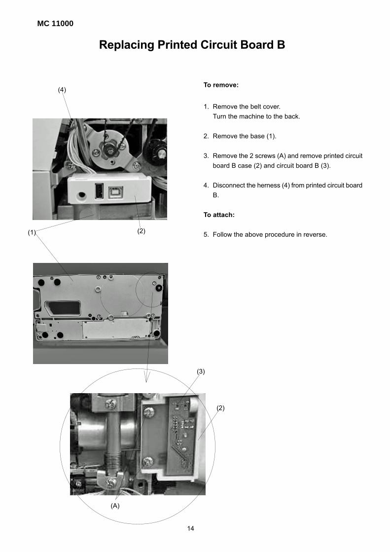
Replacing Printed Circuit Board B
To remove:
1. Remove the belt cover.
Turn the machine to the back.
2. Remove the base (1).
3. Remove the 2 screws (A) and remove printed circuit
board B case (2) and circuit board B (3).
4. Disconnect the herness (4) from printed circuit board
B.
To attach:
5. Follow the above procedure in reverse.(1) (2)
(2)
(3)
(4)
14
(A)
(B)
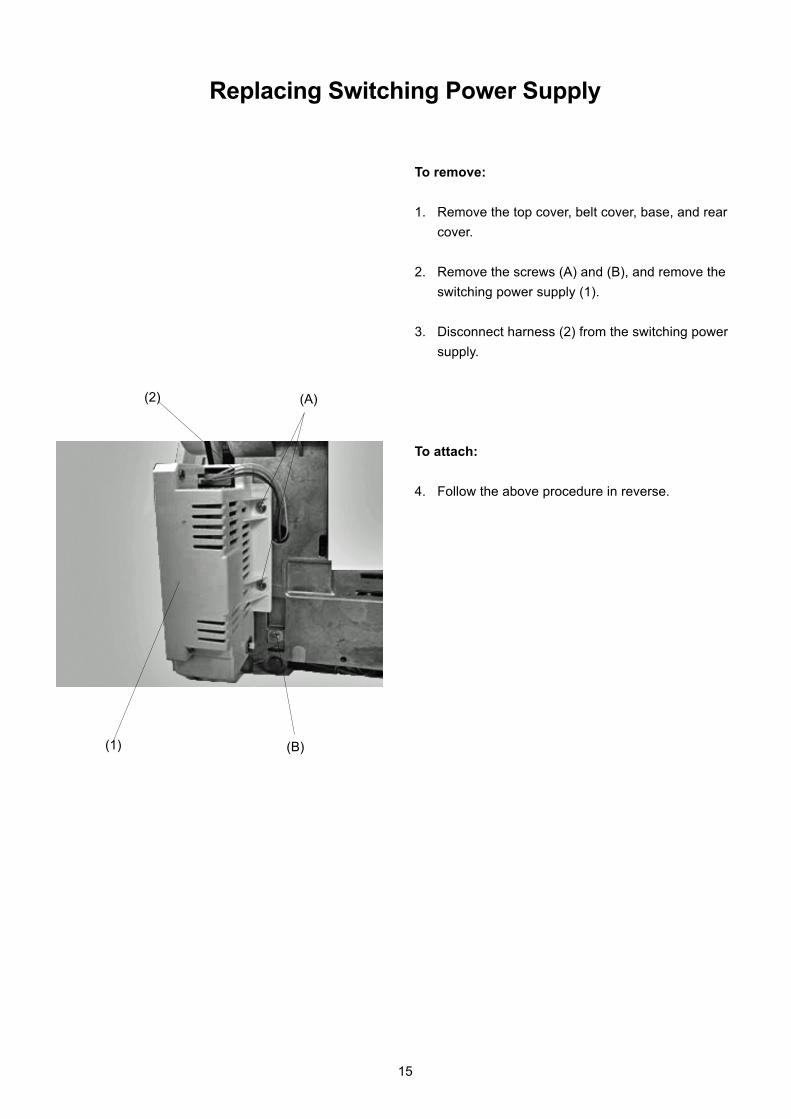
Replacing Switching Power Supply
To remove:
1. Remove the top cover, belt cover, base, and rear
cover.
2. Remove the screws (A) and (B), and remove the
switching power supply (1).
3. Disconnect harness (2) from the switching power
supply.
To attach:
4. Follow the above procedure in reverse.
(1)
(2)
15
MC 11000
(A)
(A)
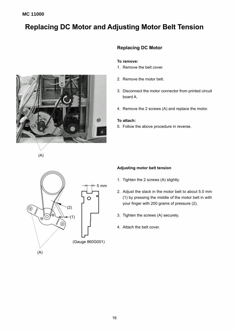
Replacing DC Motor and Adjusting Motor Belt Tension
Replacing DC Motor
To remove:
1. Remove the belt cover.
2. Remove the motor belt.
3. Disconnect the motor connector from printed circuit
board A.
4. Remove the 2 screws (A) and replace the motor.
To attach:
5. Follow the above procedure in reverse.
Adjusting motor belt tension
1. Tighten the 2 screws (A) slightly.
2. Adjust the slack in the motor belt to about 5.0 mm
(1) by pressing the middle of the motor belt in with
your finger with 200 grams of pressure (2).
3. Tighten the screws (A) securely.
4. Attach the belt cover.
(1)
(2)
16
5 mm
(Gauge 860G001)
A = B
(A)
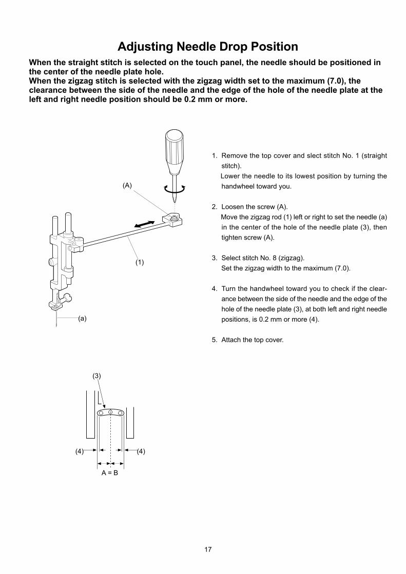
Adjusting Needle Drop PositionWhen the straight stitch is selected on the touch panel, the needle should be positioned inthe center of the needle plate hole.When the zigzag stitch is selected with the zigzag width set to the maximum (7.0), theclearance between the side of the needle and the edge of the hole of the needle plate at theleft and right needle position should be 0.2 mm or more.
1. Remove the top cover and slect stitch No. 1 (straight
stitch).
Lower the needle to its lowest position by turning the
handwheel toward you.
2. Loosen the screw (A).
Move the zigzag rod (1) left or right to set the needle (a)
in the center of the hole of the needle plate (3), then
tighten screw (A).
3. Select stitch No. 8 (zigzag).
Set the zigzag width to the maximum (7.0).
4. Turn the handwheel toward you to check if the clear-
ance between the side of the needle and the edge of the
hole of the needle plate (3), at both left and right needle
positions, is 0.2 mm or more (4).
5. Attach the top cover.
(1)
(a)
(3)
(4)(4)
17

MC 11000
(A)
(A)
Adjusting Hook TimingWhen stitch No. 2 is selected, the amount the needle bar travel from its lowest position tothe position where the tip of the rotary hook exactly meets the right side of the needleshould be 3.25 to 3.55 mm.
1. Remove the presser foot, needle plate and bobbin holder.
2. Remove the extension table and bed cover.
3. Turn the power switch on and select stitch No. 2.
4. Press the ADJUST key and set the zigzag width to 0 bymanual adjustment, then turn the power
switch off.
5. Lower the needle (6) to its lowest position (1) by turningthe handwheel toward you.
6. In this situation, make sure that the convex of the feedlifting cam is right under the cam as shown (2). Loosenthe 2 screws (A) of the lower shaft gear (3).
7. Raise the needle bar further 3.4 mm (4) from the lowestposition (1).
8. Turn the lower shaft gear (3) until the tip of the rotaryhook meets with the right side of the needle (5).
Tighten the 2 screws (A) of the lower shaft gear (3).
9. Attach the bobbin holder, needle plate and presser foot.
10. Attach the bed cover and extension table.
[Alternative way of adjustment]Before proceeding this adjustment, check the needle barheight applying the [Alternative way of adjustment] (seepage 19).
1. Remove the presser foot, needle plate and bobbin holder.
2. Remove the extension table and bed cover.
3. Turn the power switch on and select the stitch No. 8.Set the zigzag width the maximun at the left needleposition.
4. Adjust the hook timing so that the distance between thetip of hook and the top of the needle eye is 1.8 mmwhen the tip of the hook meets with the right side of theneedle as the needle bar travels upward at the leftneedle position.
5. Attach the bobbin holder, needle plate and presser foot.
6. Attach the bed cover and extension table.
(1)
(2)
(3)
(4)
(5)(6)
5º5º
181.8 mm (Gauge 860G001)

1. Remove the presser foot, needle plate and bobbin
holder.
2. Turn the power switch on and select the stitch No. 2.
3. Press ADJUST key and set the zigzag width to 0,
then turn the power switch off.
4. Turn the handwheel to raise needle bar (1) from its low-
est position until the tip of the rotary hook meets the
right side of the needle (2).
5. Open the face cover and loosen screw (A) as shown.
6. Move the needle bar (1) up or down to adjust the needle
bar height.
7. Tighten the screw (A). Be sure that the groove (3) on
the needle bar is facing exactly forward.
8. Close the face cover.
9. Reattach the bobbin holder, needle plate and presser
foot.
[Alternative way of adjustment]
1. Raise the needle to its highest position.
2. In this condition, the distance between the tip of needle
and the surface of the needle plate should be 16.3 mm.
(A)
Adjusting Needle Bar HeightThe standard distance between the upper edge of the needle eye and the tip of the rotary
hook should be in the range of 1.6 - 2.0 mm when the rotary hook meets the right side of the
needle as the needle travels up from its lowest position.
(1)
(2)
(3)
Needle #14
Rotary hook race Top of needle eye
Surface of hook race
1.6 - 2.0 mm
19
1.8 mm
(Gauge 860G001)
16.3 mm
(Gauge 860G001)

MC 11000
(C)
(B)
(A)
Adjusting Clearance between Needle and Hook
The clearance between the needle and rotary hook should be -0.10 to + 0.05 mm.
1. Remove the extension plate, needle, needle plate, bob-
bin holder, and bed cover, and attach the Test pin (1).
2. Turn the power switch on and select stitch No. 8, then
set the zigzag width to 7.0 by pressing ADJUST key.
3. Loosen the screws (A), (B) and (C) and tighten the screw
(C) slightly.
4. Turn the handwheel toward you and adjust the clear-
ance between the test pin (1) and the tip of rotary hook
(2) to - 0.10 to + 0.05 mm by moving the rotary hook set
plate (3) up or down.
5. Tighten the screws (A), (B) and (C) firmly.
6. Check the rotary hook driver gear and the lower shaft
gear backlash.
If gears engage tightly or loosely, check the section en-
titled Adjusting Backlash between Hook Drive and Lower
Shaft Gear.
7. Reattach the bed cover, bobbin holder, needle plate,
extension table and needle.
(1)
(2)
(3)
0.10 to + 0.05 mm
20

(A)
A
B
Adjusting Backlash between Hook Drive Gear and Lower
Shaft Gear
The rotational play of the hook should be 0.8 mm or less when the tip of the rotary hook is
within the width of the feed dog as shown below.
Adjust the backlash after adjusting the clearance between the needle and the rotary hook.
To check:
1. Turn the power switch off.
2. Remove the extension table and bed cover.
3. Loosen the hexagonal socket screw (A).
Jog the hook race with your fingers to check the rotary
play. If the play is larger than 0.8 mm or the gears do
not turn smoothly, adjust the backlash as follows.
Adjustment procedure:
1. Turn the lower shaft bushing (1) (eccentric), in the
direction of A when the play at rotary hook tip is too
large.
2. Turn the lower shaft bushing (1) (eccentric), in the
direction of B when the play at rotary hook tip is too
small.
3. Tighten the hexagonal socket screw (A).
4. Reattach the bed cover and extension table.
(1) Lower shaft bushing
(2) Play of the rotary hook should be 0.8 mm or less.
(3) Tip of rotary hook
(1)
(2)
(3)
21
MC 11000
(A)
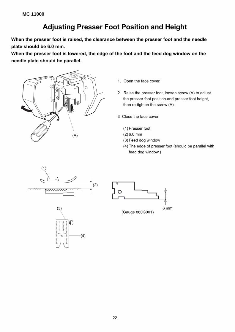
Adjusting Presser Foot Position and Height
When the presser foot is raised, the clearance between the presser foot and the needle
plate should be 6.0 mm.
When the presser foot is lowered, the edge of the foot and the feed dog window on the
needle plate should be parallel.
1. Open the face cover.
2. Raise the presser foot, loosen screw (A) to adjust
the presser foot position and presser foot height,
then re-tighten the screw (A).
3 Close the face cover.
(1) Presser foot
(2) 6.0 mm
(3) Feed dog window
(4) The edge of presser foot (should be parallel with
feed dog window.)
(1)
(2)
(3)
(4)
22
6 mm(Gauge 860G001)
(A) (B)
(C)
(D)
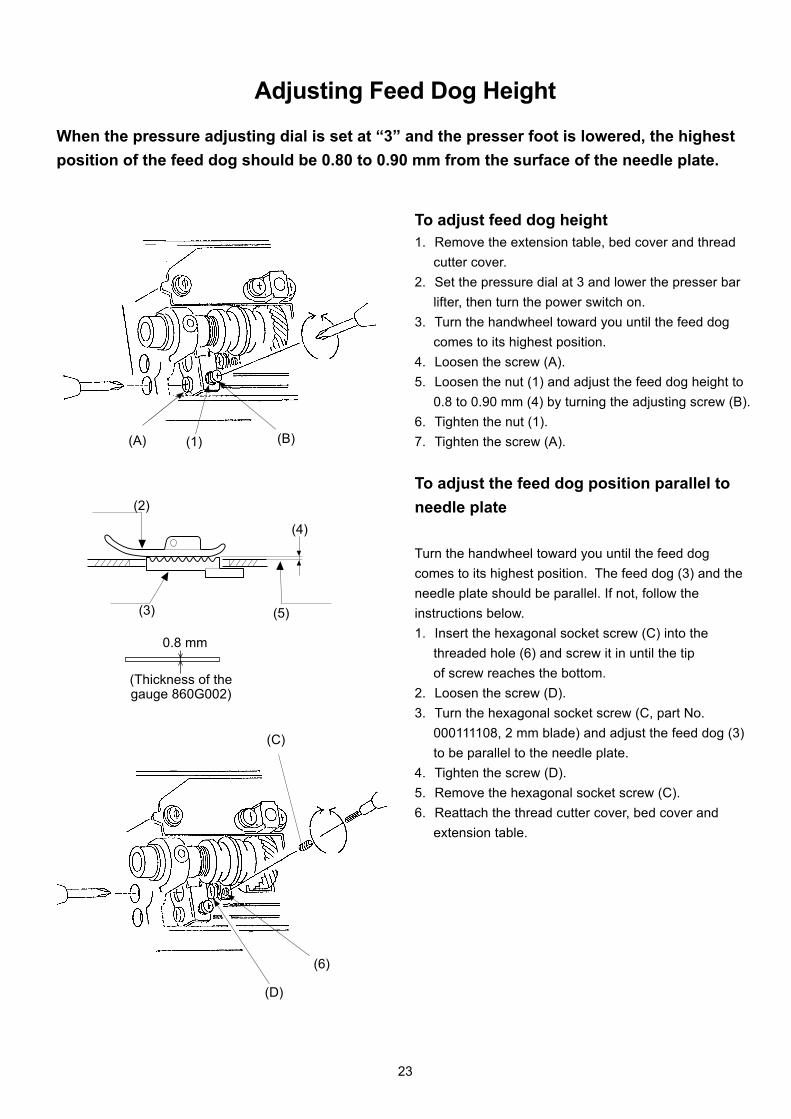
Adjusting Feed Dog Height
When the pressure adjusting dial is set at “3” and the presser foot is lowered, the highest
position of the feed dog should be 0.80 to 0.90 mm from the surface of the needle plate.
To adjust feed dog height1. Remove the extension table, bed cover and thread
cutter cover.
2. Set the pressure dial at 3 and lower the presser bar
lifter, then turn the power switch on.
3. Turn the handwheel toward you until the feed dog
comes to its highest position.
4. Loosen the screw (A).
5. Loosen the nut (1) and adjust the feed dog height to
0.8 to 0.90 mm (4) by turning the adjusting screw (B).
6. Tighten the nut (1).
7. Tighten the screw (A).
To adjust the feed dog position parallel to
needle plate
Turn the handwheel toward you until the feed dog
comes to its highest position. The feed dog (3) and the
needle plate should be parallel. If not, follow the
instructions below.
1. Insert the hexagonal socket screw (C) into the
threaded hole (6) and screw it in until the tip
of screw reaches the bottom.
2. Loosen the screw (D).
3. Turn the hexagonal socket screw (C, part No.
000111108, 2 mm blade) and adjust the feed dog (3)
to be parallel to the needle plate.
4. Tighten the screw (D).
5. Remove the hexagonal socket screw (C).
6. Reattach the thread cutter cover, bed cover and
extension table.
(1)
(2)
(3)
(4)
(5)
(6)
23
0.8 mm
(Thickness of thegauge 860G002)

MC 11000
(A)
(3)
Adjusting Height of Embroidery Foot P
The space between the needle plate and the bottom surface of the foot (P) should be
0.7 to 1.5 mm when the needle bar is at its lowest position.
(1)
(2)
(4)
24
1. Set the pressure dial at 2 and remove the
top cover.
2. Lower the needle bar to its lowest position and lower
the presser bar lifter.
3. Insert a 0.8 mm thickness gauge (1) between
the embroidery foot P (2) and the needle plate (3).
4. While pressing the presser bar actuator (4) down
against the upper shaft cam, loosen the screw (A)
and push it down in the direction of the arrow, then
tighten the screw (A) again.
5. Reattach the top cover.
(Set the pressure dial at 3.)
NOTE: After this adjustment, Foot sensor adjustment must
be performed. (See page 32)
0,8 mm
(Thickness of Gauge 860G001)

Even
(A)
MainSlave DC1
PH Sensor
H
X
Adjusting Shield Plate PositionWhen the machine is set for zigzag stitching, the needle should start to swing 8.3 to 8.7 mm
above the surface of the needle plate.
1. Remove the belt cover and base.
2. To set up the machine in Adjust Mode, turn the power
switch on while pressing the Start/Stop and reverse
buttons. (Keep pressing the button until the LCD
shows the adjusting window.)
3. Press PHSensor on the touch panel.
4. Turn the handwheel toward you and raise the needle
between 8.3 and 8.7 mm (1) above the surface of the
needle plate.
5. Remove the base and loosen the screw (A) of the shield
plate (2). Turn the shield plate until the PH sensor sig-
nal changes from L to H, and tighten the screw (A).
6. Position the right face of the shield plate (3) in the cen-
ter of slit of the sensor and tighten screw (A).
7. Reattach the base and belt cover.
(1)
(2)
(3)
Sensor (feed)
Sensor (thread cutter)
0.5 - 1.5 mm
(3)
(2)
Needle #14
25
8.7 8.3 mm mm
(Gauge 860G001)

MC 11000
(B)
(A)
Adjusting Tension Release MechanismWhen the presser foot lifter is raised, the tension release mechanism should work
correctly. If not, adjust as follows.Adjusting tension release claw
1. Remove the top cover unit.
2. Lower the presser foot and turn the thread tension
dial (1) until the convex part (2) of the tension dial is
aligned with the tension release claw (3).
In this condition, loosen the screw (A) and adjust the
tension release adjusting plate (4) to touch the
tension disc supporter (5) .
The tension discs should be opened slightly.
3. Tighten the screw (A).
Adjusting the thread releasing plate
4. Lower the presser foot, turn the thread tension dial
until the flat surface part touches the releasing claw
(3).
5. Loosen the screw (B).
6. Set the thread releasing lever (7) so that it touches
the thread release plate (5) slightly and tighten the
screw (B).
7. When the presser foot is raised, the tension discs
should be opened.
Note: The clearance between the tension disc supporter
and the thread releasing plate should be 0.5 to 1.0
mm (8) when the presser foot is lowered.
(1)
(2)
(3)
(4)
(5)
(7)
(8)
(4)
(5)
Presser footsensor switch
Thread releasingplate
26
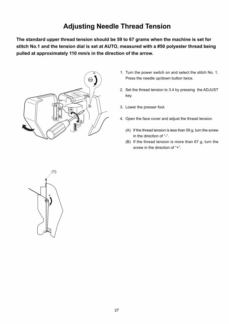
Adjusting Needle Thread Tension
The standard upper thread tension should be 59 to 67 grams when the machine is set for
stitch No.1 and the tension dial is set at AUTO, measured with a #50 polyester thread being
pulled at approximately 110 mm/s in the direction of the arrow.
1. Turn the power switch on and select the stitch No. 1.
Press the needle up/down button twice.
2. Set the thread tension to 3.4 by pressing the ADJUST
key.
3. Lower the presser foot.
4. Open the face cover and adjust the thread tension.
(A) If the thread tension is less than 59 g, turn the screw
in the direction of “-”.
(B) If the thread tension is more than 67 g, turn the
screw in the direction of “+”.
(1)
27

MC 11000
(A)
(B)
Replacing and Adjusting Threader PlateIf the hook on the threader plate is damaged, replace it as follows.
To replace:
1. Remove the foot holder.
2. Turn the power switch on. Raise the needle by press-
ing the needle up/down button.
3. Lower the threader by pushing the threader button (1).
4. Turn power switch off.
5. Loosen the 2 screws (A) and replace the threader plate
(2).
To adjust:
1. If threader hook (3) thrusts or hits against either the
left or right edge of the needle eye: Loosen the 2
screws (A) and adjust the position of the threader
plate (2).
2. If the threader hook (3) thrusts against either the top
or bottom edge of the needle eye, or misses the
needle eye, open the face cover and loosen the
screw (B). Move the threader position adjusting
holder (4) up or down to adjust the hook position.
(1)
(2)(3)
(2)
(4)
VIEW-X
VIEW-X
Needle
28
(B)
(A)
3 mm
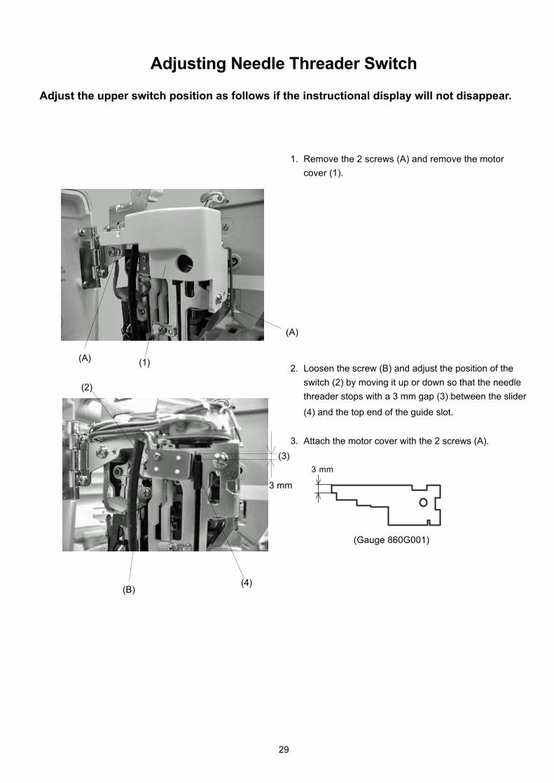
Adjusting Needle Threader Switch
Adjust the upper switch position as follows if the instructional display will not disappear.
1. Remove the 2 screws (A) and remove the motor
cover (1).
2. Loosen the screw (B) and adjust the position of the
switch (2) by moving it up or down so that the needle
threader stops with a 3 mm gap (3) between the slider
(4) and the top end of the guide slot.
3. Attach the motor cover with the 2 screws (A).
(1)
(A)
(2)
(4)
29
3 mm
(3)
(Gauge 860G001)
MC 11000
PRESS MARK
á@
4
2
5
ADJUSTMENT END
OK
1
3
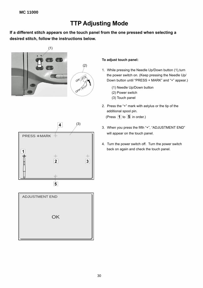
TTP Adjusting ModeIf a different stitch appears on the touch panel from the one pressed when selecting a
desired stitch, follow the instructions below.
To adjust touch panel:
1. While pressing the Needle Up/Down button (1),turn
the power switch on. (Keep pressing the Needle Up/
Down button until “PRESS + MARK” and “+” appear.)
2. Press the “+” mark with astylus or the tip of the
additional spool pin.
(Press to in order.)
3. When you press the fifth “+”, “ADJUSTMENT END”
will appear on the touch panel.
4. Turn the power switch off. Turn the power switch
back on again and check the touch panel.
(1) Needle Up/Down button
(2) Power switch
(3) Touch panel
1
(1)
(2)
(3)
30
5
(A) (B)
(A)(B)
MainSlave DC1
8 Adjust
88888888
XINITIALIZE
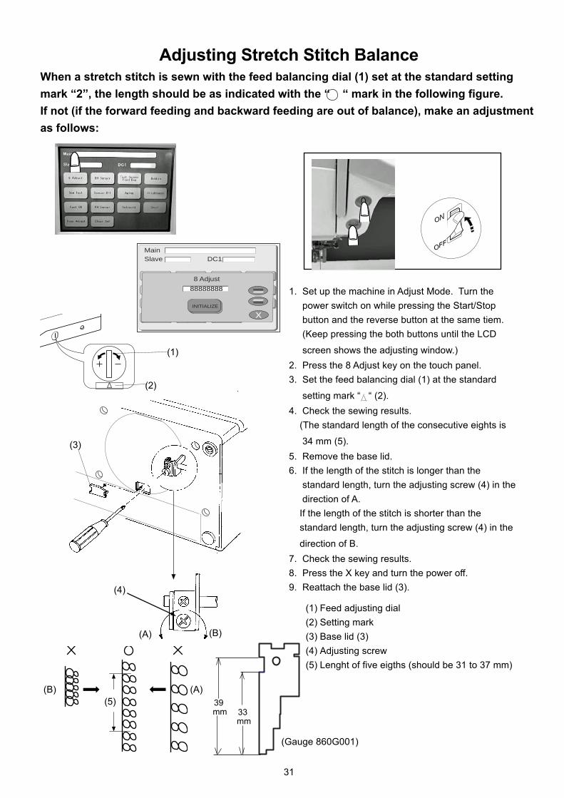
Adjusting Stretch Stitch BalanceWhen a stretch stitch is sewn with the feed balancing dial (1) set at the standard setting
mark “2”, the length should be as indicated with the “ “ mark in the following figure.
If not (if the forward feeding and backward feeding are out of balance), make an adjustment
as follows:
1. Set up the machine in Adjust Mode. Turn the
power switch on while pressing the Start/Stop
button and the reverse button at the same tiem.
(Keep pressing the both buttons until the LCD
screen shows the adjusting window.)
2. Press the 8 Adjust key on the touch panel.
3. Set the feed balancing dial (1) at the standard
setting mark “ “ (2).
4. Check the sewing results.
(The standard length of the consecutive eights is
34 mm (5).
5. Remove the base lid.
6. If the length of the stitch is longer than the
standard length, turn the adjusting screw (4) in the
direction of A.
If the length of the stitch is shorter than the
standard length, turn the adjusting screw (4) in the
direction of B.
7. Check the sewing results.
8. Press the X key and turn the power off.
9. Reattach the base lid (3).
(1) Feed adjusting dial
(2) Setting mark
(3) Base lid (3)
(4) Adjusting screw
(5) Lenght of five eigths (should be 31 to 37 mm)
(1)
(2)
(3)
(4)
(5)
31
33 mm
39 mm
(Gauge 860G001)
MC 11000
SET
MainSlave DC1
Foot UD
H
X
(A)(1)
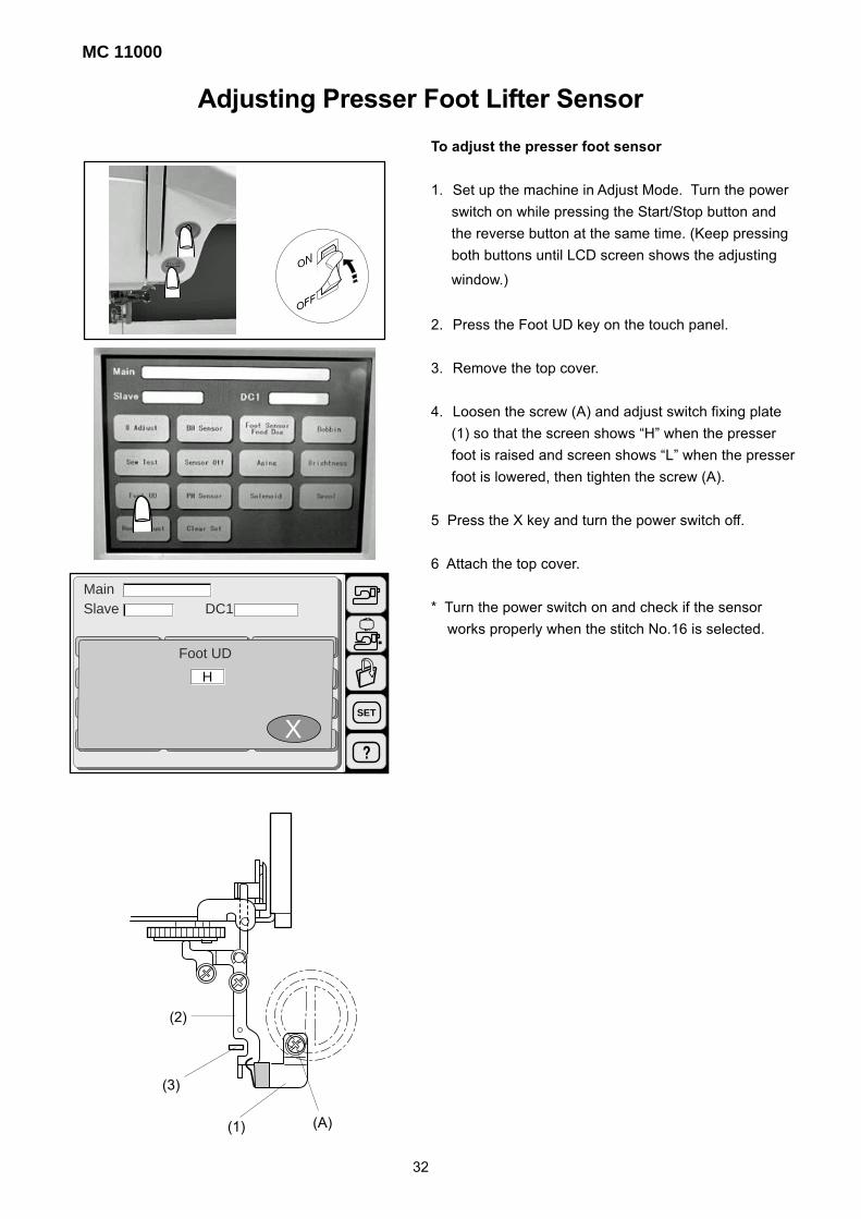
Adjusting Presser Foot Lifter Sensor
To adjust the presser foot sensor
1. Set up the machine in Adjust Mode. Turn the power
switch on while pressing the Start/Stop button and
the reverse button at the same time. (Keep pressing
both buttons until LCD screen shows the adjusting
window.)
2. Press the Foot UD key on the touch panel.
3. Remove the top cover.
4. Loosen the screw (A) and adjust switch fixing plate
(1) so that the screen shows “H” when the presser
foot is raised and screen shows “L” when the presser
foot is lowered, then tighten the screw (A).
5 Press the X key and turn the power switch off.
6 Attach the top cover.
* Turn the power switch on and check if the sensor
works properly when the stitch No.16 is selected.
(2)
(3)
32
(A)(B)
MainSlave DC1
BH Sensor
H
X
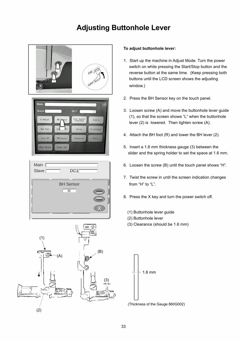
Adjusting Buttonhole Lever
To adjust buttonhole lever:
1. Start up the machine in Adjust Mode. Turn the power
switch on while pressing the Start/Stop button and the
reverse button at the same time. (Keep pressing both
buttons until the LCD screen shows the adjusting
window.)
2. Press the BH Sensor key on the touch panel.
3. Loosen screw (A) and move the buttonhole lever guide
(1), so that the screen shows “L” when the buttonhole
lever (2) is lowered. Then tighten screw (A).
4. Attach the BH foot (R) and lower the BH lever (2).
5. Insert a 1.6 mm thickness gauge (3) between the
slider and the spring holder to set the space at 1.6 mm.
6. Loosen the screw (B) until the touch panel shows “H”.
7. Twist the screw in until the screen indication changes
from “H” to “L”.
8. Press the X key and turn the power switch off.
(1) Buttonhole lever guide
(2) Buttonhole lever
(3) Clearance (should be 1.6 mm)
(1)
(2)
(3)
33
(Thickness of the Gauge 860G002)
1.6 mm

MC 11000
(A)
MainSlave DC1
Check Foot/Feed Dog
L
X
LH
Adjusting Presser Foot Sensor
To adjust foot sensor position
1. Set up the machine in Adjust Mode. Turn the power
witch on while pressing the Start/Stop button and the
reverse button at the same time. (Keep pressing both
buttons until LCD screen shows the adjusting window.)
2. Press the Foot Sensor key on the touch panel.
3. Attach the zigzag foot (3), set the pressure dial at “3”
and lower the feed dog and the presser foot.
4. Lower the needle bar to the lowest position.
5. Loosen the foot sensor shield plate screw (A).
6. Move the foot sensor shield plate (1) to the left-most po-
sition until it touches the sensor (2) lightly. (“L” will ap-
pear on the touch panel.)
7. Remove the zigzag foot (3) and lower the presser bar.
(H will appear on the touch panel.)
To check:
8. Set the pressure dial at 2.
9. Change the foot to embroidery foot P and slowly lower
the embroidery foot P.
10.Turn the handwheel to raise the needle bar to its
highest position.
11.While slightly moving the foot sensor shield plate (1)
within its range of play, check the indication on the
touch panel.
If the screen shows “H”, the foot sensor is properly
adjusted. Press the X key and turn the power switch
off.
If the screen shows “L”, readjust the height of embroi-
dery foot P and proceed with the adjusting steps again
from step 1 to 7.
(1)(2)
(3) (4)
34
MainSlave DC1
Bobbin Thread
X
0
250256
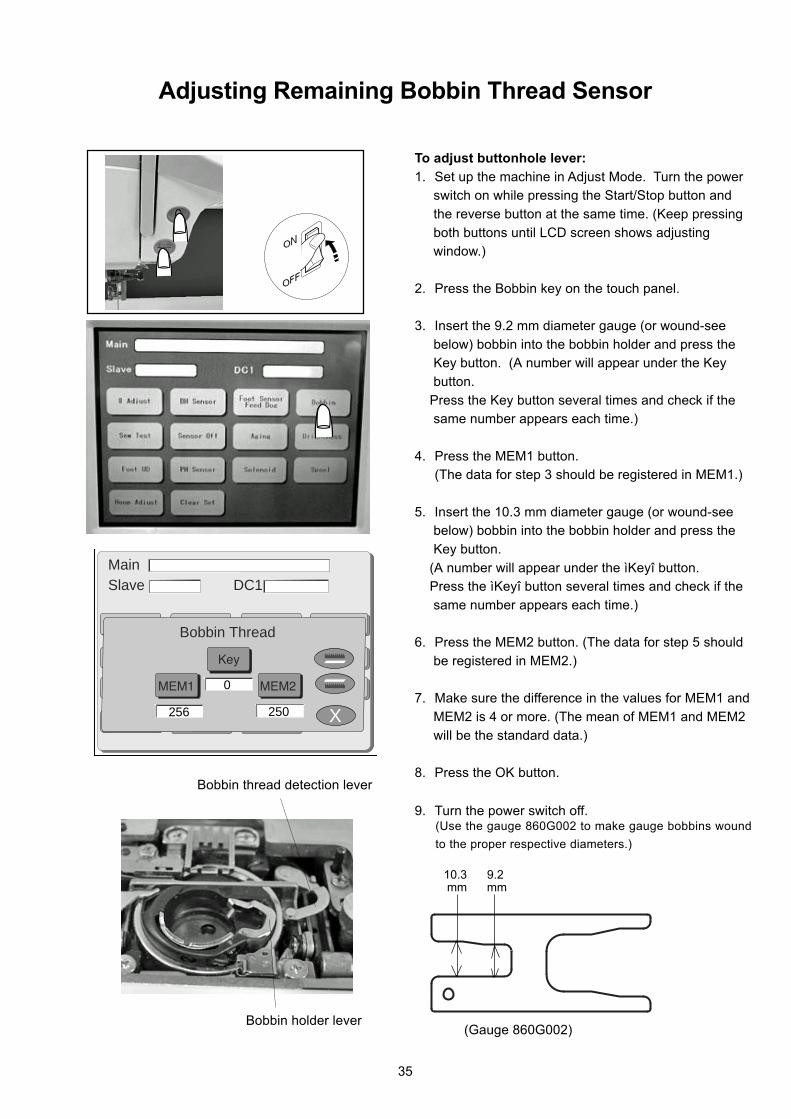
Bobbin holder lever
Bobbin thread detection lever
Adjusting Remaining Bobbin Thread Sensor
To adjust buttonhole lever:
1. Set up the machine in Adjust Mode. Turn the powerswitch on while pressing the Start/Stop button and
the reverse button at the same time. (Keep pressing
both buttons until LCD screen shows adjustingwindow.)
2. Press the Bobbin key on the touch panel.
3. Insert the 9.2 mm diameter gauge (or wound-see
below) bobbin into the bobbin holder and press theKey button. (A number will appear under the Key
button.
Press the Key button several times and check if thesame number appears each time.)
4. Press the MEM1 button.(The data for step 3 should be registered in MEM1.)
5. Insert the 10.3 mm diameter gauge (or wound-seebelow) bobbin into the bobbin holder and press the
Key button.
(A number will appear under the ìKeyî button. Press the ìKeyî button several times and check if the
same number appears each time.)
6. Press the MEM2 button. (The data for step 5 should
be registered in MEM2.)
7. Make sure the difference in the values for MEM1 and
MEM2 is 4 or more. (The mean of MEM1 and MEM2
will be the standard data.)
8. Press the OK button.
9. Turn the power switch off.
35
10.3 9.2 mm mm
(Use the gauge 860G002 to make gauge bobbins wound
to the proper respective diameters.)
(Gauge 860G002)
MC 11000
5 mm
(A)
Solenoid
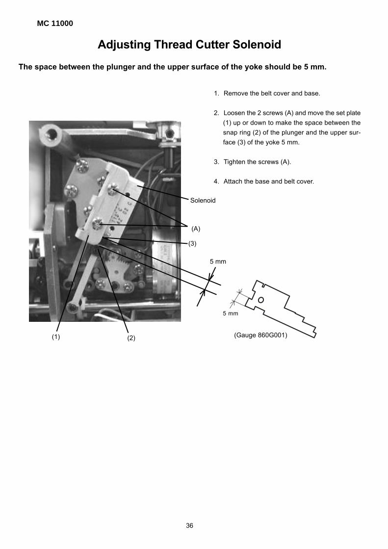
Adjusting Thread Cutter Solenoid
The space between the plunger and the upper surface of the yoke should be 5 mm.
1. Remove the belt cover and base.
2. Loosen the 2 screws (A) and move the set plate
(1) up or down to make the space between the
snap ring (2) of the plunger and the upper sur-
face (3) of the yoke 5 mm.
3. Tighten the screws (A).
4. Attach the base and belt cover.
(1) (2)
(3)
36
5 mm
(Gauge 860G001)

(A)
5 mm
Adjusting Upper Shaft Clutch SolenoidThe space between the plunger and the upper surface of the yoke should be 5 mm.
1. Remove the belt cover.
2. Loosen the 2 screws (A) and move the yoke (1) up or
down to make a space of 5 mm between the snap ring
(2) of the plunger and the upper surface of the yoke.
3. Tighten the screws (A).
4. Attach the belt cover.
To adjust:
(1)
(2)
37
5 mm (Gauge 860G001)

MC 11000
1. Start the machine in Adjust Mode. Turn the power
switch on while pressing the Start/Stop button and
the reverse button at the same time. (Keep pressing
both buttons until LCD screen shows adjusting
window.)
2. Press the Solenoid key on the touch panel.
3. Remove the bed cover, base and thread cutter cover.
4. Lower the needle bar to its lowest position.
5. When lowering actuator arm (1), “L” will be indicated
on the Solenoid 2 window of the touch panel.
If the screen dose not show “L”, loosen screw (A) and
adjust it by moving the switch left or right.
6. When raising actuator arm (1), “H” will be indicated on
the Solenoid 2 window of the touch panel.
If the screen does not show “H”, loosen the screw (A)
and adjust it by moving the switch left or right.
7. Attach the thread cutter cover, bed cover and base.
(A)
MainSlave DC1
Solenoid
X
Solenoid 2 Solenoid 3Solenoid 1
H H84
Adjusting Thread Cutter Switch
(1)
SEWING THREAD CUTTING
“H” “L”
38

1. Loosen the setscrew (1). Turn the bobbin winder stop-
per (2) to adjust the amount of allowable thread.
* If too much thread is allowed, turn the stopper in the
direction A.
* If tnot enough thread is allowed, turn the stopper in the
direction B.
2. Tighten the setscrew (1) firmly.
A
B
Adjusting Bobbin Winder Stopper
The amount of thread wound on the bobbin should be between 16.5 and 19.5 mm in diameter.
16.5 -19.5 mm
(1)
(2)
39
19.5 mm
16.5 mm
(Gauge 860G002)

MC 11000
5.45 - 5.75 mm
VIEW - A
VIEW - A
Adjusting Thread Drawing Lever
The standard height of the thread drawing lever from the seat of the hook race for the
bobbin holder should be in the range of 5.45 - 5.75 mm.
1. Remove the needle plate and bobbin holder.
2. Loosen the hexagonal bolt (1) and adjust the distance
between the thread drawing lever (2) and the seat of
the hook race for bobbin holder (3) to between 5.45
mm and 5.75 mm by moving the thread drawing lever
up or down.
3. Tighten the hexagonal bolt.
4. Attach the bobbin holder and needle plate
(1)
(2)
(3)
40
5.5 mm
(Gauge 860G001)
(2)

(C)
(C)(C)
(C)
(C)
16.5 mm
4.3 - 5.3 mm (X)
(A)
(B)
(Y)
Adjusting X and Y Sensors
1. Turn the power switch on to set to the initial setting.
2. Turn the power switch off and remove the base
unit.
3. Remove the Y carriage cover (1), X carriage cover
(2), X carriage cap (3) and embroidery base covers
(4) and (5).
4. Loosen the screw (A) to adjust dimension (Y) to be
between 16 mm and 17 mm by moving the Y sensor
attaching plate (6).
5. Loosen the screw (B) to adjust dimension (X) to be
between 4.3 mm and 5.3 mm by moving the X sensor
attaching plate (7).
7. Attach the Y carriage cover (1), X carriage cover (2),
X carriage cap (3) and embroidery base covers (4)
and (5).
8. Attach the base.
(6)
(1) (2)
(3)
(4)
(5)
(7)
41
(Gauge 860G001)
17 mm16 mm
5.3 mm4.3 mm
MC 11000
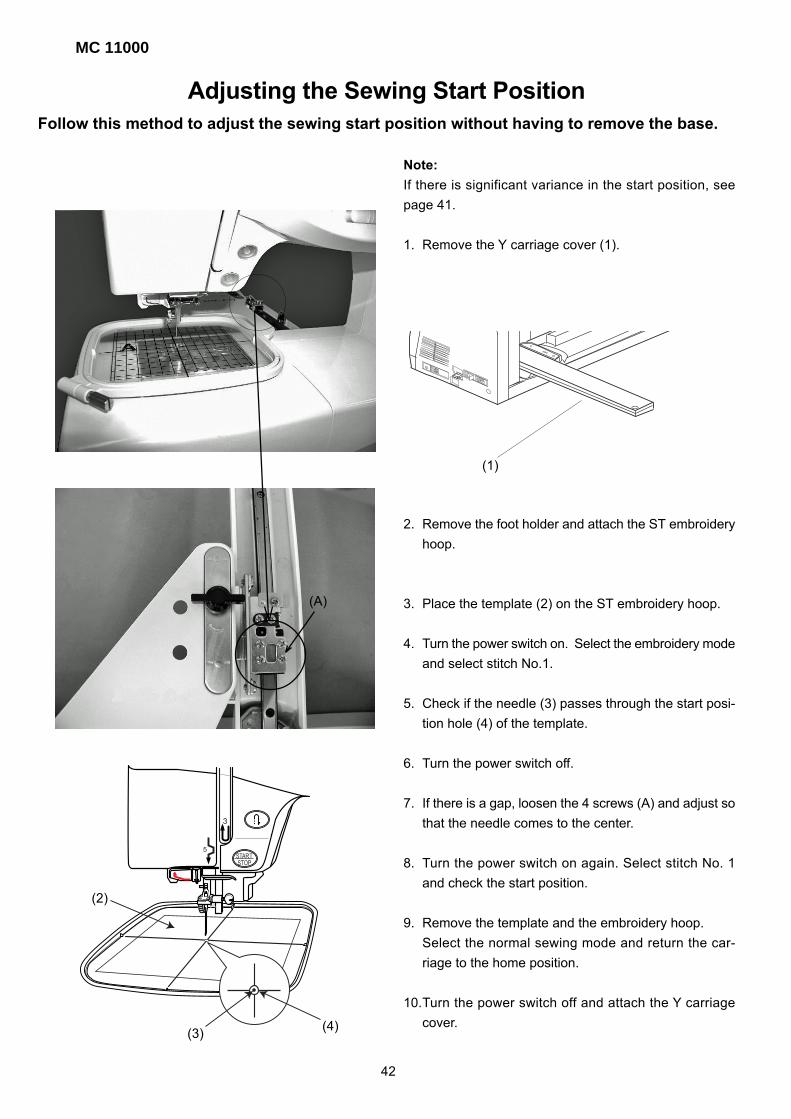
Follow this method to adjust the sewing start position without having to remove the base.
Adjusting the Sewing Start Position
Note:
If there is significant variance in the start position, see
page 41.
1. Remove the Y carriage cover (1).
2. Remove the foot holder and attach the ST embroidery
hoop.
3. Place the template (2) on the ST embroidery hoop.
4. Turn the power switch on. Select the embroidery mode
and select stitch No.1.
5. Check if the needle (3) passes through the start posi-
tion hole (4) of the template.
6. Turn the power switch off.
7. If there is a gap, loosen the 4 screws (A) and adjust so
that the needle comes to the center.
8. Turn the power switch on again. Select stitch No. 1
and check the start position.
9. Remove the template and the embroidery hoop.
Select the normal sewing mode and return the car-
riage to the home position.
10.Turn the power switch off and attach the Y carriage
cover.
(A)
(1)
(2)
(4)(3)
42

Setting Position of Thread Take Up lever
(B)- long
(E)
Insert the needle bar crank into the take up crank (C)
so that the flat part of the needle bar crank (D) faces
the long setscrew (B). Tighten the setscrew (B), then
the short setscrew (A).
(A)- short
(C)
(D)
43
MC 11000
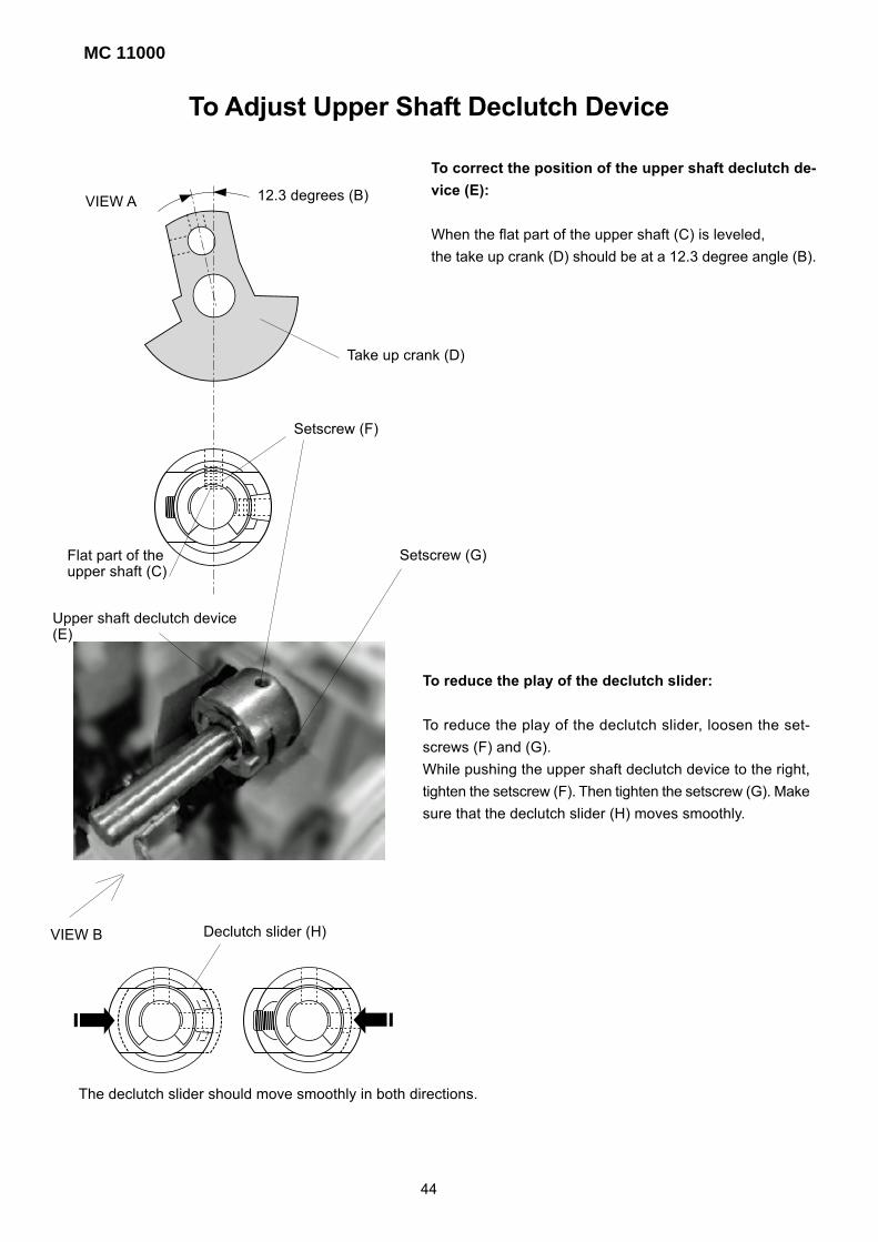
To Adjust Upper Shaft Declutch Device
To correct the position of the upper shaft declutch de-
vice (E):
When the flat part of the upper shaft (C) is leveled,
the take up crank (D) should be at a 12.3 degree angle (B).
To reduce the play of the declutch slider:
To reduce the play of the declutch slider, loosen the set-
screws (F) and (G).
While pushing the upper shaft declutch device to the right,
tighten the setscrew (F). Then tighten the setscrew (G). Make
sure that the declutch slider (H) moves smoothly.
12.3 degrees (B)VIEW A
Setscrew (F)
Setscrew (G)
VIEW B
Take up crank (D)
Flat part of theupper shaft (C)
Upper shaft declutch device(E)
Declutch slider (H)
The declutch slider should move smoothly in both directions.
44
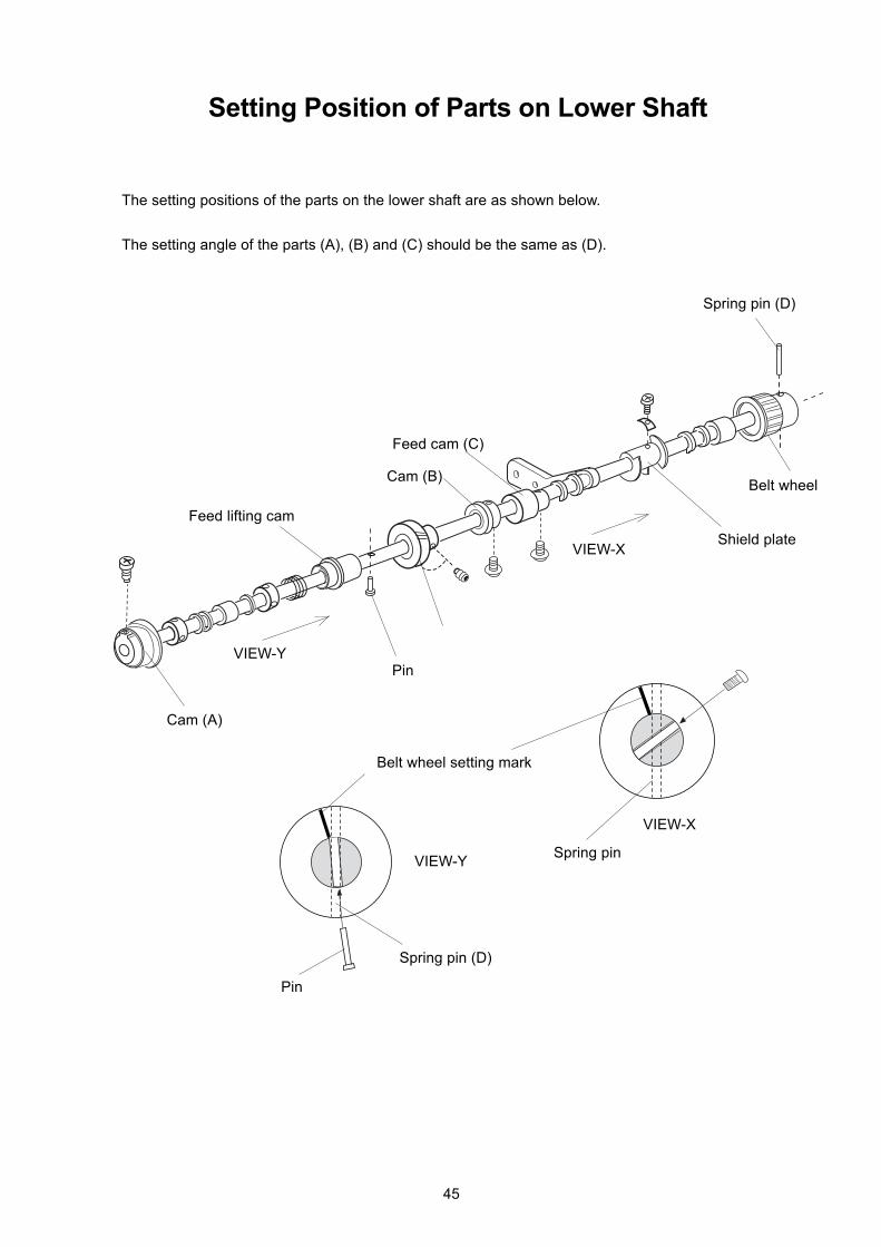
The setting positions of the parts on the lower shaft are as shown below.
The setting angle of the parts (A), (B) and (C) should be the same as (D).
Setting Position of Parts on Lower Shaft
Feed lifting cam
Cam (B)
Feed cam (C)
Spring pin (D)
Belt wheel
Shield plate
Cam (A)
Pin
VIEW-X
VIEW-Y
VIEW-X
VIEW-Y
Pin
Spring pin
Spring pin (D)
Belt wheel setting mark
45
MC 11000
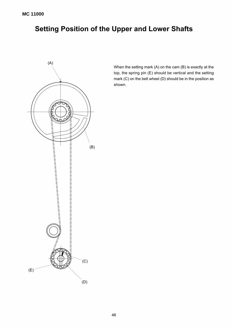
Setting Position of the Upper and Lower Shafts
When the setting mark (A) on the cam (B) is exactly at the
top, the spring pin (E) should be vertical and the setting
mark (C) on the belt wheel (D) should be in the position as
shown.
(A)
(B)
(C)
(D)
(E)
46