service manual - combitec · 7.outdoor performance curves…… ... by integrating intelligential...
TRANSCRIPT
Commercial Air Conditioning
SERVICE MANUAL
Models Inverter R410a 50/60HZ
Indoor: YHKJXH012BAM--FX YHKJXH018BAM--FX YHKJXH024BAR--FX YHKJXH028BAR--FX YHKJXH036BAR--FX YHKJXH048BAR--FX YHKJXH048BAR--FX YHKJXH060BAR--FX YHFJXH012BAM--FX YHFJXH018BAM--FX YHFJXH024BAR--FX YHFJXH028BAR--FX YHFJXH036BAR--FX YHFJXH048BAR--FX YHFJXH048BAR--FX YHFJXH060BAR--FX YHDJXH012BAM--GX YHDJXH018BAM--GX YHDJXH024BAR--GX YHEJXH024BAR--GX YHEJXH028BAR--GX YHEJXH036BAR--GX YHEJXH048BAR--GX YHEJXH048BAR--GX YHGJXH048BAR--GX YHGJXH048BAR--GX YHGJXH060BAR--GX
Outdoor: YHUJYH024BAR-A-XYHUJYH028BAR-A-XYHUJYH036BAR-A-XYHUJYH048BAR-A-XYHUJYH048BAS-A-XYHUJYH060BAS-A-X
1

CONTENTS Contents………………………………………………………......2 1. Description of products & features…………………………..3
12. Controller functions…...…………………………………....152
2. Specification…………………………………………………...53. Dimensions…………………………………………………....334. Pipe and wiring installation…..……………………………...405. PCB photo, wiring diagram and function description……..926. Diagnostic code and troubleshooting.…………………….1227. Outdoor performance curves………..……………………..1288. Indoor air velocity and temperature distribution curves....1339. Air flow and static pressure chart…………………………..13510. Noise level…………………………………………………..13711. Sensor characteristic….…………………………………...150
2
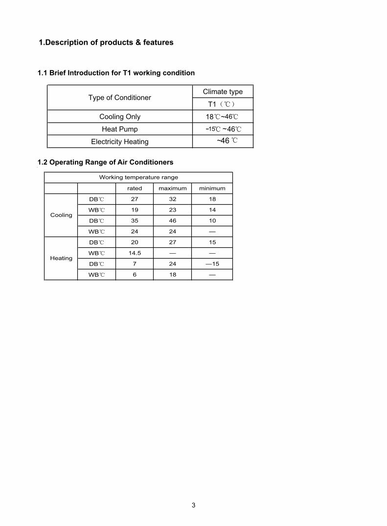
1.Description of products & features
1.2 Operating Range of Air Conditioners
rated maximum minimum
DB 32 18
WB 19 23 14
DB 35 46
WB 24 24 —
DB 20 27 15
WB 14.5 —
DB
WB
Working temperature range
Cooling
Heating
Climate type
T1
Cooling Only
Electricity Heating
18 ~
~~
15
1.1 Brief Introduction for T1 working condition
27
46
4646
Type of Conditioner
Heat Pump -
6 18 —
7 24 ―15
—
10
3

1.3 Product features
Super match
By integrating intelligential technology of Haier A/C group, super match air conditioner,
with universal indoor and outdoor units, make more intelligent and flexible choices on
purchasing, easier inventory management to every customer.
Good for choice
Multi-choice of capacity and appearance of indoor unit according to various rooms.
DC scroll compressor
The highly efficient scroll compressor is equipped with a “flexible Mechanism” that
allows movement in the axial direction of the frame supporting the cradle scroll. This
greatly reduces both leakage and friction loss, ensuring very high efficiency
throughout the speed range.
DC inverter technology
Powerful startup: Haier DC inverter system can startup and running at maximum
frequency very quickly in order to reach the set temperature in the shorter time, which
brings you great comfort experience.
Minimum running: Haier DC inverter system will reduce the frequency and running
smoothly according to the real load after reach the set temperature. The system
funning cost reduced drastically which brings you real benefit of money saving.
Automatic control
Precise control: The temperature sensor can measure the temperature precisely with
only 0.5 tolerance, which transfers the exact requirement to the system to adjust the
compressor frequency accordingly.
Once reach the set temperature, the system adjust the frequency smoothly according
to the real time request and always maintain the temperature without fluctuation.
Wider operation range
Haier DC inverter system provide much wider working range that is suitable for
special cooling, heating requirement.
The Unitary Smart DC inv. outdoor unit default production with AC fan motor, DC fan
motor is for optional choice with additional cost.
4

Model name YORK
Unit YHKJZH012BAM-AFX YHKJZH018BAM-AFX
Outdoor YHUJYH012BAM-A-X YHUJYH018BAM-A-X
Indoor YHKJXH012BAM--FX YHKJXH018BAM--FXPower supply V/Ph/Hz 230/1/50 230/1/50
Rated Cooling
Capacity kW(min~max) 3.5(0.9~4.5) 4.8(1.8~5.8)
Input W(min~max) 1080(280~1650) 1490(550~2000)
Rated current A 5 6.8EER W/W 3.24 3.22
SEER W/W 5.1 5.1
Rated Heating
Capacity Btu/h 12371.4 17375
Input W(min~max) 995(280~1650) 1580(600~2000)
Rated current A 4.7 6.7COP W/W 3.62 3.22
SCOP W/W 3.64 3.4
Heating P design(-10 ) kW 3.4 4.8
Moisture Removal l/h 1.6 1.8Max. input consumption W 1800 2000
Max. current A 8 9.5Starting current A 3 3
Operation Control Wired&Wireless Wired&Wireless
Indoor coil
Number of row 2 2
Fin spacing mm 1.25 1.25
Fin material Hydrophilic Aluminium Hydrophilic Aluminium
Tube outside diameter mm 7 7
Tube material Inner Grooved copper tube Inner Grooved copper tube
Number of circuit 4 4
Indoor fan motor
Input W 30 62Output W 11 18
Running current A 0.18 0.24
Capacitor uF 2 2
Speed (Hi/Me/Lo) rpm 690/520/560 795/690/550
Indoor air flow at 0/50/100 Pa(Hi/Me/Lo) m3/h 620/520/450 700/620/500Indoor noise level(Sound power level) (Hi/
Me/Lo) dB(A) 53/49/45 55/50/47
Indoor noise level (Sound pressure level)(Hi/Me/Lo) dB(A) 40/36/32 42/37/35
Indoor dimension
Unit (WxDxH) mm 570×570×260 570×570×260
Packing (WxDxH) mm 718×680×380 718×680×380
Indoor weightNet kg 18.5 18.5
Gross kg 23 23
Panel dimension
Unit (WxDxH) mm 700×700×60 700×700×60
Packing (WxDxH) mm 740×750×115 740×750×115
Panel weightNet kg 2.8 2.8
Gross kg 4.8 4.8
5
2.Specification
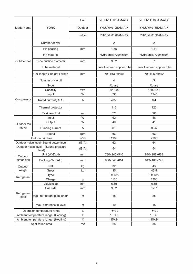
Model name YORK
Unit YHKJZH012BAM-AFX YHKJZH018BAM-AFX
Outdoor YHUJYH012BAM-A-X YHUJYH018BAM-A-X
Indoor YHKJXH012BAM--FX YHKJXH018BAM--FX
Outdoor coil
Number of row 2 2
Fin spacing mm 1.75 1.41
Fin material Hydrophilic Aluminium Hydrophilic Aluminium
Tube outside diameter mm 9.52 7
Tube material Inner Grooved copper tube Inner Grooved copper tube
Coil length x height x width mm 793 x43.3x550 793 x26.6x462
Number of circuit 4 3
Compressor
Type Rotary RotaryCapacity W/h 9043.92 13992.48
Input W 690 1245
Rated current(RLA) A 2650 8.4
Thermal protector 115 120
Refrigerant oil ml 370 500
Outdoor fan motor
Input W 62 56Output W 40 41
Running current A 0.2 0.25
Speed rpm 850 860Outdoor air flow m3/h 1900 2200
Outdoor noise level (Sound power level) dB(A) 62 64Outdoor noise level (Sound pressure
level) dB(A) 54 54
Outdoor dimension
Unit (WxDxH) mm 780×245×540 810×288×688
Packing (WxDxH) mm 930×340×614 949×406×745
Outdoor weight
Net kg 32 43Gross kg 35 45.5
RefrigerantType R410A R410A
Charge g 1100 1300
Refrigerant pipe
Liquid side mm 6.35 6.35Gas side mm 9.52 12.7
Max. refrigerant pipe length m 15 25
Max. difference in level m 10 15
Operation temperature range 16~30 16~30Ambient temperature range (Cooling) 18~43 18~43Ambient temperature range (Heating) -15~24 -15~24
Application area m2 25 35
6

Model name YORK
Unit YHKJZH024BAR-AFX YHKJZH028BAR-AFX
Outdoor YHUJYH024BAR-A-X YHUJYH028BAR-A-X
Indoor YHKJXH024BAR--FX YHKJXH028BAR--FXPower supply V/Ph/Hz 230/1/50(60) 230/1/50(60)
Rated Cooling
Capacity kW(min~max) 6.9(1.8~7.5) 7.8(2.0~8.7)
Input W(min~max) 2225(500~2600) 2590(500~3800)
Rated current A 9.4 10.8EER W/W 3.1 3.01
SEER W/W 5.217391304 5.239130435
Rated Heating
Capacity Btu/h 24885 29008
Input W(min~max) 2010(500~2600) 2530(500~3800)
Rated current A 9 11.6COP W/W 3.63 3.36
SCOP W/W 3.6 3.4
Heating P design(-10 ) kW 6.5 7.8
Moisture Removal l/h 2.5 2.8Max. input consumption W 2600 4200
Max. current A 12 19Starting current A 3 3
Operation Control Wired&Wireless Wired&Wireless
Indoor coil
Number of row 2 2
Fin spacing mm 1.3 1.3
Fin material Hydrophilic Aluminium Hydrophilic Aluminium
Tube outside diameter mm 7 7
Tube material Inner Grooved copper tube Inner Grooved copper tube
Number of circuit 8 8
Indoor fan motor
Input W 140 140Output W 40 40
Running current A 0.65 0.65
Capacitor uF 3 3
Speed (Hi/Me/Lo) rpm 710/620/520 710/620/520
Indoor air flow at 0/50/100 Pa(Hi/Me/Lo) m3/h 1300/1100/870 1300/1100/870Indoor noise level(Sound power level) (Hi/
Me/Lo) dB(A) 59/57/52 61/59/57
Indoor noise level (Sound pressure level)(Hi/Me/Lo) dB(A) 46/44/39 48/46/44
Indoor dimension
Unit (WxDxH) mm 840×840×240 840×840×240
Packing (WxDxH) mm 930×930×330 930×930×330
Indoor weightNet kg 26.8 26.8
Gross kg 32.6 32.6
Panel dimension
Unit (WxDxH) mm 950×950×60 950×950×60
Packing (WxDxH) mm 985×985×115 985×985×115
Panel weightNet kg 6 6
Gross kg 7.5 7.5
7

Model name YORK
Unit YHKJZH024BAR-AFX YHKJZH028BAR-AFX
Outdoor YHUJYH024BAR-A-X YHUJYH028BAR-A-X
Indoor YHKJXH024BAR--FX YHKJXH028BAR--FX
Outdoor coil
Number of row 2 2
Fin spacing mm 1.65 1.7
Fin material Hydrophilic Aluminium Hydrophilic Aluminium
Tube outside diameter mm 7.94 7.94
Tube material Inner Grooved copper tube Inner Grooved copper tube
Coil length x height x width mm 840 x39.9x700 855 x38.1x792
Number of circuit 4 6
Compressor
Type Rotary RotaryCapacity W/h 13992.48 24333.264
Input W 1245 2200(60Hz)
Rated current(RLA) A 8.4 9.7
Thermal protector 120 120
Refrigerant oil ml 500 870
Outdoor fan motor
Input W 85 145Output W 70 100
Running current A 0.4 0.4
Speed rpm 880 900Outdoor air flow m3/h 3000 3500
Outdoor noise level (Sound power level) dB(A) 68 69Outdoor noise level (Sound pressure
level) dB(A) 57 58
Outdoor dimension
Unit (WxDxH) mm 860×308×730 948×340×840
Packing (WxDxH) mm 995×420×815 1040×430×1000
Outdoor weight
Net kg 49 64Gross kg 52 73
RefrigerantType R410A R410A
Charge g 1600 2600
Refrigerant pipe
Liquid side mm 9.52 9.52Gas side mm 15.88 15.88
Max. refrigerant pipe length m 25 30
Max. difference in level m 15 20
Operation temperature range 16~30 16~30Ambient temperature range (Cooling) -10~46 -10~46Ambient temperature range (Heating) -15~24 -15~24
Application area m2 45 55
8

Model name YORK
Unit YHKJZH036BAR-AFX YHKJZH048BAR-AFX
Outdoor YHUJYH036BAR-A-X YHUJYH048BAR-A-X
Indoor YHKJXH036BAR--FX YHKJXH048BAR--FXPower supply V/Ph/Hz 230/1/50(60) 230/1/50(60)
Rated Cooling
Capacity kW(min~max) 9.3(2.0~10.3) 12.1(6.0~13.8)
Input W(min~max) 3000(500~3800) 4115(2000~6000)
Rated current A 12.87 18EER W/W 3.097826087 2.94
SEER W/W 5.347826087 /
Rated Heating
Capacity Btu/h 32030.55 43121.875
Input W(min~max) 2780(500~3800) 4070(2000~6000)
Rated current A 12.1 18COP W/W 3.38 3.10
SCOP W/W 3.6 /
Heating P design(-10 ) kW 9.1 /
Moisture Removal l/h 3 3.8Max. input consumption W 4500 6000
Max. current A 20 26Starting current A 3 3
Operation Control Wired&Wireless Wired&Wireless
Indoor coil
Number of row 2 2
Fin spacing mm 1.4 1.4
Fin material Hydrophilic Aluminium Hydrophilic Aluminium
Tube outside diameter mm 7 7
Tube material Inner Grooved copper tube Inner Grooved copper tube
Number of circuit 11 11
Indoor fan motor
Input W 150 150Output W 50 50
Running current A 0.68 0.68
Capacitor uF 8 8
Speed (Hi/Me/Lo) rpm 680/610/530 680/610/530
Indoor air flow at 0/50/100 Pa(Hi/Me/Lo) m3/h 1600/1450/1300 1600/1450/1300Indoor noise level(Sound power level) (Hi/
Me/Lo) dB(A) 62/60/57 /
Indoor noise level (Sound pressure level)(Hi/Me/Lo) dB(A) 49/47/44 49/47/44
Indoor dimension
Unit (WxDxH) mm 840×840×290 840×840×290
Packing (WxDxH) mm 930×930×390 930×930×390
Indoor weightNet kg 31 31
Gross kg 37 37
Panel dimension
Unit (WxDxH) mm 950×950×60 950×950×60
Packing (WxDxH) mm 985×985×115 985×985×115
Panel weightNet kg 6 6
Gross kg 7.5 7.5
9

Model name YORK
Unit YHKJZH036BAR-AFX YHKJZH048BAR-AFX
Outdoor YHUJYH036BAR-A-X YHUJYH048BAR-A-X
Indoor YHKJXH036BAR--FX YHKJXH048BAR--FX
Outdoor coil
Number of row 3 2
Fin spacing mm 1.55 1.4
Fin material Hydrophilic Aluminium Hydrophilic Aluminium
Tube outside diameter mm 7.0 7.94
Tube material Inner Grooved copper tube Inner Grooved copper tube
Coil length x height x width mm 960 x39.9x792 792x38.1x995
Number of circuit 8 in 4 out 9
Compressor
Type Rotary RotaryCapacity W/h 24333.264 33718.464
Input W 2200(60Hz) 3010
Rated current(RLA) A 9.7 9.3
Thermal protector 120 120
Refrigerant oil ml 870 870
Outdoor fan motor
Input W 145 180Output W 100 151
Running current A 0.4 0.8
Speed rpm 900 850Outdoor air flow m3/h 3500 4200
Outdoor noise level (Sound power level) dB(A) 69 73Outdoor noise level (Sound pressure
level) dB(A) 58 59
Outdoor dimension
Unit (WxDxH) mm 948×340×840 1008×410×830
Packing (WxDxH) mm 1040×430×1000 1130×490×930
Outdoor weight
Net kg 65 82Gross kg 74 93
RefrigerantType R410A R410A
Charge g 2700 2850
Refrigerant pipe
Liquid side mm 9.52 9.52Gas side mm 15.88 19.05
Max. refrigerant pipe length m 30 50
Max. difference in level m 20 30
Operation temperature range 16~30 16~30Ambient temperature range (Cooling) -10~46 -10~46Ambient temperature range (Heating) -15~24 -15~24
Application area m2 65 82
10

Model name YORK
Unit YHKJZH048BAS-AFX YHKJZH060BAS-AFX
Outdoor YHUJYH048BAS-A-X YHUJYH060BAS-A-X
Indoor YHKJXH048BAR--FX YHKJXH060BAR--FXPower supply V/Ph/Hz 400/3/50(60) 400/3/50(60)
Rated Cooling
Capacity kW(min~max) 12.1(6.0~13.8) 14.4(3.7~15.1)
Input W(min~max) 4296(2000~6000) 5124(2000~6500)
Rated current A 6.5 8.5EER W/W 2.815217391 2.81
SEER W/W / /
Rated Heating
Capacity Btu/h 42304.5 52507.35
Input W(min~max) 4102(2000~6000) 5110(2000~6500)
Rated current A 6.7 8.5COP W/W 3.02 3.01
SCOP W/W / /
Heating P design(-10 ) kW / /
Moisture Removal l/h 3.8 5Max. input consumption W 6000 6500
Max. current A 10 10.5Starting current A 3 3
Operation Control Wired&Wireless Wired&Wireless
Indoor coil
Number of row 2 2
Fin spacing mm 1.4 1.3
Fin material Hydrophilic Aluminium Hydrophilic Aluminium
Tube outside diameter mm 7 7
Tube material Inner Grooved copper tube Inner Grooved copper tube
Number of circuit 11 10
Indoor fan motor
Input W 150 190Output W 50 60
Running current A 0.68 1.2
Capacitor uF 8 4.5
Speed (Hi/Me/Lo) rpm 680/610/530 670/550/460
Indoor air flow at 0/50/100 Pa(Hi/Me/Lo) m3/h 1600/1450/1300 1980/1750/1500Indoor noise level(Sound power level) (Hi/
Me/Lo) dB(A) / /
Indoor noise level (Sound pressure level)(Hi/Me/Lo) dB(A) 49/47/44 49/44/42
Indoor dimension
Unit (WxDxH) mm 840×840×290 1230×840×280
Packing (WxDxH) mm 930×930×390 1325×920×370
Indoor weightNet kg 31 38.6
Gross kg 37 45.7
Panel dimension
Unit (WxDxH) mm 950×950×60 1340×950×80
Packing (WxDxH) mm 985×985×115 1400×995×115
Panel weightNet kg 6 8.4
Gross kg 7.5 12.7
11

Model name YORK
Unit 2 2
Outdoor 1.4 1.5
Indoor Hydrophilic Aluminium Hydrophilic Aluminium
Outdoor coil
Number of row 7.94 7.94
Fin spacing mm Inner Grooved copper tube Inner Grooved copper tube
Fin material 792x38.1x995 970x38.1x1200
Tube outside diameter mm 9 10
Tube material Rotary Rotary
Coil length x height x width mm 33718.464 47710.944
Number of circuit 3010 4270
Compressor
Type 9.3 12Capacity W/h 120 120
Input W 870 1400
Rated current(RLA) A 257 120
Thermal protector 142 100
Refrigerant oil ml 1.1 0.4
Outdoor fan motor
Input W 850 930Output W 4200 6500
Running current A 73 75
Speed rpm 59 60Outdoor air flow m3/h 1008×410×830 948×340×1250
Outdoor noise level (Sound power level) dB(A) 1130×490×930 1095×410×1400Outdoor noise level (Sound pressure
level) dB(A) 82 96
Outdoor dimension
Unit (WxDxH) mm 93 106
Packing (WxDxH) mm R410A R410A
Outdoor weight
Net kg 2850 3300Gross kg 9.52 9.52
RefrigerantType 19.05 19.05
Charge g 50 50
Refrigerant pipe
Liquid side mm 30 30Gas side mm 16~30 16~30
Max. refrigerant pipe length m -10~46 -10~46
Max. difference in level m -15~24 -15~24
Operation temperature range 82 100Ambient temperature range (Cooling) -10~46 -10~46Ambient temperature range (Heating) -15~24 -15~24
Application area m2 65 82
12

model YORKUnit YHFJZH012BAM-AFX YHFJZH018BAM-AFX
Outdoor YHUJYH012BAM-A-X YHUJYH018BAM-A-XIndoor YHFJXH012BAM--FX YHFJXH018BAM--FX
Power supply V/Ph/Hz 230/1/50 230/1/50
Rated Cooling
Capacity Btu/h 12286 17064Capacity kW(min~ max) 3.6(0.9~ 4.5) 5.0(1.7~ 5.3)Input W(min~ max) 1118(280~ 1650) 1500(550~ 2000)Rated current A 5 6.8EER W/W 3.22 3.33 SEER W/W 5.3 5.6
Rated Heating
Capacity Btu/h 13992 19111Capacity kW(min~ max) 4.1(1~ 4.8) 5.6(1.8~ 6.0)Input W(min~ max) 1100(280~ 1650) 1509(600~ 2000)Rated current A 4.9 6.5COP W/W 3.73 3.71 SCOP W/W 3.8 3.6 Heating P design(-10 ) kW 3.4 5
Moisture Removal l/h 1.6 1.8 Max. input consumption W 1800 2000Max. current A 8.0 9.5 Starting current A 3 3Operation Control Wired&Wireless Wired&Wireless
Indoor coil
Number of row 3 3Fin spacing mm 1.5 1.5Fin material Hydrophilic Aluminium Hydrophilic AluminiumTube outside diameter mm 7 7
Tube material Inner Grooved copper tube Inner Grooved copper tube
Coil length x height x width mm 797x39.9x252 797x39.9x252Number of circuit 4 4
Indoor fan motor
Input W 79 96Output W 28 55Running current A 0.32 0.55Capacitor uF 2 3Speed (Hi/Me/Lo) rpm 1100/1025/825 1220/1190/1050
Indoor air flow at 0/50/100 Pa(Hi/Me/Lo) m3/h 650/550/450 800/720/650Indoor noise level(Sound power level) (Hi/Me/Lo) dB(A) 54/50/46 57/54/49
Indoor noise level (Sound pressure level)(Hi/Me/Lo) dB(A) 41/37/33 44/41/36
Indoor dimension Unit (WxDxH) mm 990×199×655 990×199×655Packing (WxDxH) mm 1150×300×750 1150×300×750
Indoor weight Net kg 26.3 28.3Gross kg 32.3 34.3
Outdoor coil
Number of row 2 2Fin spacing mm 1.75 1.41Fin material Hydrophilic Aluminium Hydrophilic AluminiumTube outside diameter mm 9.52 7
Tube material Inner Grooved copper tube Inner Grooved copper tube
Coil length x height x width mm 793 x43.3x550 793 x26.6x462Number of circuit 4 3
Compressor
Type Rotary RotaryCapacity W/h 9043.92 13992.48Input W 690 1245Rated current(RLA) A 2650 8.4Thermal protector 115 120Refrigerant oil ml 370 500
13

model YORKUnit YHFJZH012BAM-AFX YHFJZH018BAM-AFX
Outdoor YHUJYH012BAM-A-X YHUJYH018BAM-A-XIndoor YHFJXH012BAM--FX YHFJXH018BAM--FX
O u t d o o r f a n motor
Input W 62 56Output W 40 41Running current A 0.2 0.25Speed rpm 850 860
Outdoor air flow m3/h 1900 2200Outdoor noise level (Sound power level) dB(A) 62 64Outdoor noise level (Sound pressure level) dB(A) 54 54O u t d o o r dimension
Unit (WxDxH) mm 780×245×540 810×288×688Packing (WxDxH) mm 930×340×614 949×406×745
Outdoor weight Net kg 32 43Gross kg 35 45.5
Refrigerant Type R410A R410ACharge g 1100 1300
Refrigerant pipe
Liquid side mm 6.35 6.35Gas side mm 9.52 12.7Max. refrigerant pipe length m 15 25Max. difference in level m 10 15
Operation temperature range 16~ 30 16~ 30Ambient temperature range (Cooling) 18~ 43 18~ 43Ambient temperature range (Heating) -15~ 24 -15~ 24Application area m2 24 35
14

model YORKUnit YHFJZH024BAR-AFX YHFJZH028BAR-AFX
Outdoor YHUJYH024BAR-A-X YHUJYH028BAR-A-XIndoor YHFJXH024BAR--FX YHFJXH028BAR--FX
Power supply V/Ph/Hz 230/1/50(60) 230/1/50(60)
Rated Cooling
Capacity Btu/h 21842 26620Capacity kW(min~ max) 6.4(1.8~ 6.7) 7.8(1.9~ 9.2)Input W(min~ max) 2216(500~ 2600) 2475(500~ 2600)Rated current A 9.5 10.2EER W/W 2.89 3.15 SEER W/W 5.2 5.7
Rated Heating
Capacity Btu/h 23890 30751Capacity kW(min~ max) 7.0(2.3~ 7.3) 9.0(2.0~ 9.6)Input W(min~ max) 2140(500~ 2600) 2480500~ 2600)Rated current A 9.5 10.2COP W/W 3.27 3.63 SCOP W/W 3.6 3.8 Heating P design(-10 ) kW 6.5 8
Moisture Removal l/h 2.0 2.6 Max. input consumption W 2600 4200Max. current A 12.0 19.0 Starting current A 3 3Operation Control Wired&Wireless Wired&Wireless
Indoor coil
Number of row 3 3Fin spacing mm 1.5 1.3Fin material Hydrophilic Aluminium Hydrophilic AluminiumTube outside diameter mm 7 7
Tube material Inner Grooved copper tube Inner Grooved copper tube
Coil length x height x width mm 797x39.9x252 1070x39.9x252Number of circuit 4 6
Indoor fan motor
Input W 96 145Output W 55 70Running current A 0.55 0.82Capacitor uF 3 5Speed (Hi/Me/Lo) rpm 1220/1190/1050 1145/1092/956
Indoor air flow at 0/50/100 Pa(Hi/Me/Lo) m3/h 850/800/720 1630/1537/1375Indoor noise level(Sound power level) (Hi/Me/Lo) dB(A) 57/54/49 62/58/46
Indoor noise level (Sound pressure level)(Hi/Me/Lo) dB(A) 44/41/36 49/45/43
Indoor dimension Unit (WxDxH) mm 990×199×655 1298×240×700Packing (WxDxH) mm 1150×300×750 1500×315×790
Indoor weight Net kg 28.3 37Gross kg 34.3 47
Outdoor coil
Number of row 2 2Fin spacing mm 1.65 1.7Fin material Hydrophilic Aluminium Hydrophilic AluminiumTube outside diameter mm 7.94 7.94
Tube material Inner Grooved copper tube Inner Grooved copper tube
Coil length x height x width mm 840 x39.9x700 855 x38.1x792Number of circuit 4 6
Compressor
Type Rotary RotaryCapacity W/h 13992.48 24333 Input W 1245 2200(60Hz)Rated current(RLA) A 8.4 9.7Thermal protector 120 120Refrigerant oil ml 500 870
15

model YORKUnit YHFJZH024BAR-AFX YHFJZH028BAR-AFX
Outdoor YHUJYH024BAR-A-X YHUJYH028BAR-A-XIndoor YHFJXH024BAR--FX YHFJXH028BAR--FX
O u t d o o r f a n motor
Input W 85 145Output W 70 100Running current A 0.4 0.4Speed rpm 880 900
Outdoor air flow m3/h 3000 3500Outdoor noise level (Sound power level) dB(A) 68 69Outdoor noise level (Sound pressure level) dB(A) 57 58O u t d o o r dimension
Unit (WxDxH) mm 860×308×730 948×340×840Packing (WxDxH) mm 995×420×815 1040×430×1000
Outdoor weight Net kg 49 64Gross kg 52 73
Refrigerant Type R410A R410ACharge g 1600 2600
Refrigerant pipe
Liquid side mm 9.52 9.52Gas side mm 15.88 15.88Max. refrigerant pipe length m 25 30Max. difference in level m 15 20
Operation temperature range 16~30 16~30Ambient temperature range (Cooling) -10~46 -10~46Ambient temperature range (Heating) -15~24 -15~24Application area m2 45 55
16

model YORKUnit YHFJZH036BAR-AFX YHFJZH048BAR-AFX
Outdoor YHUJYH036BAR-A-X YHUJYH048BAR-A-XIndoor YHFJXH036BAR--FX YHFJXH048BAR--FX
Power supply V/Ph/Hz 230/1/50(60) 230/1/50(60)
Rated Cooling
Capacity Btu/h 31739 42000Capacity kW(min~ max) 9.3(2.0~ 10.1) 12.3(5.5~ 13.3)Input W(min~ max) 2982(500~ 2800) 3975(2000~ 6000)Rated current A 10.9 17.5EER W/W 3.11 3.09 SEER W/W 5.6 /
Rated Heating
Capacity Btu/h 36176 47104Capacity kW(min~ max) 10.6(2.0~ 10.8) 13.8(5.5~ 15.1)Input W(min~ max) 2910(500~ 2800) 4083(2000~ 6000)Rated current A 12.8 18.5COP W/W 3.62 3.38 SCOP W/W 3.8 /Heating P design(-10 ) kW 9.1 /
Moisture Removal l/h 3.1 4.6 Max. input consumption W 4500 6000Max. current A 20.0 26.0 Starting current A 3 3Operation Control Wired&Wireless Wired&Wireless
Indoor coil
Number of row 3 3Fin spacing mm 1.3 1.5Fin material Hydrophilic Aluminium Hydrophilic AluminiumTube outside diameter mm 7 7
Tube material Inner Grooved copper tube Inner Grooved copper tube
Coil length x height x width mm 1070x39.9x252 1350x39.9x252Number of circuit 6 12
Indoor fan motor
Input W 145 198Output W 70 105Running current A 0.82 0.65Capacitor uF 5 5Speed (Hi/Me/Lo) rpm 1145/1092/956 1250/1150/1100
Indoor air flow at 0/50/100 Pa(Hi/Me/Lo) m3/h 1630/1537/1375 2000/1800/1400Indoor noise level(Sound power level) (Hi/Me/Lo) dB(A) 62/58/46 /
Indoor noise level (Sound pressure level)(Hi/Me/Lo) dB(A) 49/45/43 53/51/49
Indoor dimension Unit (WxDxH) mm 1298×240×700 1580×240×700Packing (WxDxH) mm 1500×315×790 1710×315×790
Indoor weight Net kg 37 54Gross kg 47 61
Outdoor coil
Number of row 3 2Fin spacing mm 1.55 1.4Fin material Hydrophilic Aluminium Hydrophilic AluminiumTube outside diameter mm 7.0 7.94
Tube material Inner Grooved copper tube Inner Grooved copper tube
Coil length x height x width mm 960 x39.9x792 792x38.1x995Number of circuit 8 in 4 out 9
Compressor
Type Rotary RotaryCapacity W/h 24333 33718 Input W 2200(60Hz) 3010Rated current(RLA) A 9.7 9.3Thermal protector 120 120Refrigerant oil ml 870 870
17

model YORKUnit YHFJZH036BAR-AFX YHFJZH048BAR-AFX
Outdoor YHUJYH036BAR-A-X YHUJYH048BAR-A-XIndoor YHFJXH036BAR--FX YHFJXH048BAR--FX
O u t d o o r f a n motor
Input W 145 180Output W 100 151Running current A 0.4 0.8Speed rpm 900 850
Outdoor air flow m3/h 3500 4200Outdoor noise level (Sound power level) dB(A) 69 73Outdoor noise level (Sound pressure level) dB(A) 58 59O u t d o o r dimension
Unit (WxDxH) mm 948×340×840 1008×410×830Packing (WxDxH) mm 1040×430×1000 1130×490×930
Outdoor weight Net kg 65 82Gross kg 74 93
Refrigerant Type R410A R410ACharge g 2700 2850
Refrigerant pipe
Liquid side mm 9.52 9.52Gas side mm 15.88 19.05Max. refrigerant pipe length m 30 50Max. difference in level m 20 30
Operation temperature range 16~30 16~30Ambient temperature range (Cooling) -10~46 -10~46Ambient temperature range (Heating) -15~24 -15~24Application area m2 65 85
18

model YORKUnit YHFJZH048BAS-AFX YHFJZH060BAS-AFX
Outdoor YHUJYH048BAS-A-X YHUJYH060BAS-A-XIndoor YHFJXH048BAR--FX YHFJXH060BAR--FX
Power supply V/Ph/Hz 400/3/50(60) 400/3/50(60)
Rated Cooling
Capacity Btu/h 42000 50552Capacity kW(min~ max) 12.3(5.5~ 13.3) 14.8(3.7~ 15.1)Input W(min~ max) 4040(2000~ 6000) 5028(2000~ 6500)Rated current A 6.6 8.5EER W/W 3.04 2.95 SEER W/W / /
Rated Heating
Capacity Btu/h 46464 51761Capacity kW(min~ max) 13.6(5.5~ 15.1) 15.2(3.7~ 16.5)Input W(min~ max) 4120(2000~ 6000) 4620(2000~ 6500)Rated current A 6.8 8.1COP W/W 3.30 3.28 SCOP W/W / /Heating P design(-10 ) kW / /
Moisture Removal l/h 4.6 5.1 Max. input consumption W 6000 6500Max. current A 10.0 10.5 Starting current A 3 3Operation Control Wired&Wireless Wired&Wireless
Indoor coil
Number of row 3 3Fin spacing mm 1.5 1.5Fin material Hydrophilic Aluminium Hydrophilic AluminiumTube outside diameter mm 7 7
Tube material Inner Grooved copper tube Inner Grooved copper tube
Coil length x height x width mm 1350x39.9x252 1350x39.9x252Number of circuit 12 12
Indoor fan motor
Input W 198 198Output W 105 105Running current A 0.65 0.65Capacitor uF 5 5Speed (Hi/Me/Lo) rpm 1250/1150/1100 1250/1150/1100
Indoor air flow at 0/50/100 Pa(Hi/Me/Lo) m3/h 2000/1800/1400 2000/1800/1400Indoor noise level(Sound power level) (Hi/Me/Lo) dB(A) / /
Indoor noise level (Sound pressure level)(Hi/Me/Lo) dB(A) 53/51/49 53/51/49
Indoor dimension Unit (WxDxH) mm 1580×240×700 1580×240×700Packing (WxDxH) mm 1710×315×790 1710×315×790
Indoor weight Net kg 54 54Gross kg 61 61
Outdoor coil
Number of row 2 2Fin spacing mm 1.4 1.5Fin material Hydrophilic Aluminium Hydrophilic AluminiumTube outside diameter mm 7.94 7.94
Tube material Inner Grooved copper tube Inner Grooved copper tube
Coil length x height x width mm 792x38.1x995 970x43.5x1200Number of circuit 9 10
Compressor
Type Rotary RotaryCapacity W/h 33718 47711 Input W 3010 4270Rated current(RLA) A 9.3 12Thermal protector 120 120Refrigerant oil ml 870 1400
19

model YORKUnit YHFJZH048BAS-AFX YHFJZH060BAS-AFX
Outdoor YHUJYH048BAS-A-X YHUJYH060BAS-A-XIndoor YHFJXH048BAR--FX YHFJXH060BAR--FX
O u t d o o r f a n motor
Input W 257 120Output W 142 100Running current A 1.1 0.4Speed rpm 850 930
Outdoor air flow m3/h 4200 6500Outdoor noise level (Sound power level) dB(A) 73 75Outdoor noise level (Sound pressure level) dB(A) 59 60O u t d o o r dimension
Unit (WxDxH) mm 1008×410×830 948×340×1250Packing (WxDxH) mm 1130×490×930 1095×410×1400
Outdoor weight Net kg 82 96Gross kg 93 106
Refrigerant Type R410A R410ACharge g 2850 3300
Refrigerant pipe
Liquid side mm 9.52 9.52Gas side mm 19.05 19.05Max. refrigerant pipe length m 50 50Max. difference in level m 30 30
Operation temperature range 16~30 16~30Ambient temperature range (Cooling) -10~46 -10~46Ambient temperature range (Heating) -15~24 -15~24Application area m2 83 100
20

Model name YORKUnit YHDJZH012BAM-AGX YHDJZH018BAM-AGX
Outdoor YHUJYH012BAM-A-X YHUJYH018BAM-A-XIndoor YHDJXH012BAM--GX YHDJXH018BAM--GX
Power supply V/Ph/Hz 230/1/50 230/1/50
Rated Cooling
Capacity Btu/h 11945 17064Capacity kW(min~max) 3.5(0.8~4.1) 5.0(1.7~5.5)Input W(min~max) 1080(280~1650) 1553(550~2100)Rated current A 5 6.8EER W/W 3.24 3.22 SEER W/W 5.3 5.6
Rated Heating
Capacity Btu/h 13793 19112Capacity kW(min~max) 4.0(0.9~4.4) 5.4(1.8~6.0)Input W(min~max) 1160(280~1650) 1496(600~2100)Rated current A 5.1 6.5COP W/W 3.45 3.61 SCOP W/W 3.8 3.8 Heating P design(-10~) kW 3.4 5
Moisture Removal l/h 1.5 1.9 Max. input consumption W 1200 2100Max. current A 8.0 10.0 Starting current A 3 3Operation Control Wired&Wireless Wired&Wireless
Indoor coil
Number of row 3 2Fin spacing mm 1.4 1.4Fin material Hydrophilic Aluminium Hydrophilic AluminiumTube outside diameter mm 7 7
Tube material Inner Grooved copper tube Inner Grooved copper tube
Coil length x height x width mm 434 x 39.9 x 252 895x 26.6 x 252Number of circuit 3 4
Indoor fan motor
Input W 40 90Output W 30 74Running current A 0.5 0.5Speed (Hi/Me/Lo) rpmIndoor air flow at 0/50/100Pa(Hi/Me/Lo) m3/h 550
External static pressure Pa 0/30 0/30Indoor noise level(Sound power level) (Hi/Me/Lo) dB(A) 46/41/46 49/43/39
Indoor noise level (Sound pressure level)(Hi/Me/Lo) dB(A) 33/28/23 36/30/26
Indoor dimension Unit (WxDxH) mm 850×420×185 1170×420×185Packing (WxDxH) mm 1025×525×260 1345×525×260
Indoor weight Net kg 17 25Gross kg 18 26.5
Outdoor coil
Number of row 2 2Fin spacing mm 1.75 1.41Fin material Hydrophilic Aluminium Hydrophilic AluminiumTube outside diameter mm 9.52 7
Tube material Inner Grooved copper tube Inner Grooved copper tube
Coil length x height x width mm 793 x43.3x550 793 x26.6x462Number of circuit 4 3
Compressor
Type Rotary RotaryCapacity W/h 9043.92 13992.48Input W 690 1245Rated current(RLA) A 2650 8.4Thermal protector 115 120Refrigerant oil ml 370 500
21
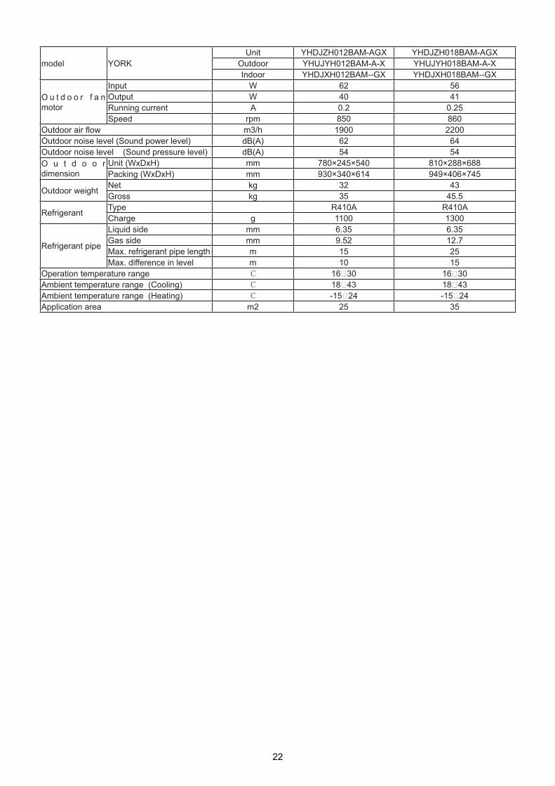
model YORKUnit YHDJZH012BAM-AGX YHDJZH018BAM-AGX
Outdoor YHUJYH012BAM-A-X YHUJYH018BAM-A-XIndoor YHDJXH012BAM--GX YHDJXH018BAM--GX
O u t d o o r f a n motor
Input W 62 56Output W 40 41Running current A 0.2 0.25Speed rpm 850 860
Outdoor air flow m3/h 1900 2200Outdoor noise level (Sound power level) dB(A) 62 64Outdoor noise level (Sound pressure level) dB(A) 54 54O u t d o o r dimension
Unit (WxDxH) mm 780×245×540 810×288×688Packing (WxDxH) mm 930×340×614 949×406×745
Outdoor weight Net kg 32 43Gross kg 35 45.5
Refrigerant Type R410A R410ACharge g 1100 1300
Refrigerant pipe
Liquid side mm 6.35 6.35Gas side mm 9.52 12.7Max. refrigerant pipe length m 15 25Max. difference in level m 10 15
Operation temperature range 16~30 16~30Ambient temperature range (Cooling) 18~43 18~43Ambient temperature range (Heating) -15~24 -15~24Application area m2 25 35
22
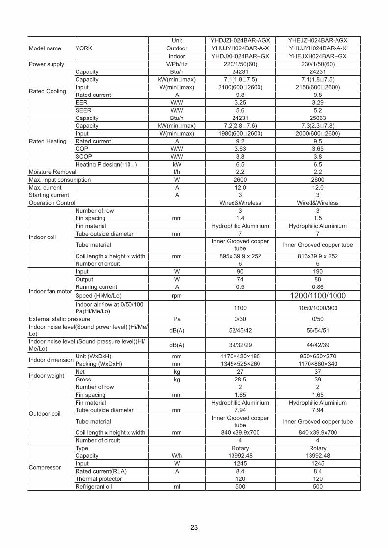
Model name YORKUnit YHDJZH024BAR-AGX YHEJZH024BAR-AGX
Outdoor YHUJYH024BAR-A-X YHUJYH024BAR-A-XIndoor YHDJXH024BAR--GX YHEJXH024BAR--GX
Power supply V/Ph/Hz 220/1/50(60) 230/1/50(60)
Rated Cooling
Capacity Btu/h 24231 24231Capacity kW(min~max) 7.1(1.8~7.5) 7.1(1.8~7.5)Input W(min~max) 2180(600~2600) 2158(600~2600)Rated current A 9.8 9.8EER W/W 3.25 3.29 SEER W/W 5.6 5.2
Rated Heating
Capacity Btu/h 24231 25063Capacity kW(min~max) 7.2(2.8~7.6) 7.3(2.3~7.8)Input W(min~max) 1980(600~2600) 2000(600~2600)Rated current A 9.2 9.5COP W/W 3.63 3.65 SCOP W/W 3.8 3.8 Heating P design(-10~) kW 6.5 6.5
Moisture Removal l/h 2.2 2.2 Max. input consumption W 2600 2600Max. current A 12.0 12.0 Starting current A 3 3Operation Control Wired&Wireless Wired&Wireless
Indoor coil
Number of row 3 3Fin spacing mm 1.4 1.5Fin material Hydrophilic Aluminium Hydrophilic AluminiumTube outside diameter mm 7 7
Tube material Inner Grooved copper tube Inner Grooved copper tube
Coil length x height x width mm 895x 39.9 x 252 813x39.9 x 252Number of circuit 6 6
Indoor fan motor
Input W 90 190Output W 74 88Running current A 0.5 0.86Speed (Hi/Me/Lo) rpm 1200/1100/1000Indoor air flow at 0/50/100Pa(Hi/Me/Lo) 1100 1050/1000/900
External static pressure Pa 0/30 0/50Indoor noise level(Sound power level) (Hi/Me/Lo) dB(A) 52/45/42 56/54/51
Indoor noise level (Sound pressure level)(Hi/Me/Lo) dB(A) 39/32/29 44/42/39
Indoor dimension Unit (WxDxH) mm 1170×420×185 950×650×270Packing (WxDxH) mm 1345×525×260 1170×860×340
Indoor weight Net kg 27 37Gross kg 28.5 39
Outdoor coil
Number of row 2 2Fin spacing mm 1.65 1.65Fin material Hydrophilic Aluminium Hydrophilic AluminiumTube outside diameter mm 7.94 7.94
Tube material Inner Grooved copper tube Inner Grooved copper tube
Coil length x height x width mm 840 x39.9x700 840 x39.9x700Number of circuit 4 4
Compressor
Type Rotary RotaryCapacity W/h 13992.48 13992.48Input W 1245 1245Rated current(RLA) A 8.4 8.4Thermal protector 120 120Refrigerant oil ml 500 500
23

model YORKUnit YHDJZH024BAR-AGX YHEJZH024BAR-AGX
Outdoor YHUJYH024BAR-A-X YHUJYH024BAR-A-XIndoor YHDJXH024BAR--GX YHEJXH024BAR--GX
O u t d o o r f a n motor
Input W 85 85Output W 70 70Running current A 0.4 0.4Speed rpm 880 880
Outdoor air flow m3/h 3000 3000Outdoor noise level (Sound power level) dB(A) 68 68Outdoor noise level (Sound pressure level) dB(A) 57 57O u t d o o r dimension
Unit (WxDxH) mm 860×308×730 860×308×730Packing (WxDxH) mm 995×420×815 995×420×815
Outdoor weight Net kg 49 49Gross kg 52 52
Refrigerant Type R410A R410ACharge g 1600 1600
Refrigerant pipe
Liquid side mm 9.52 9.52Gas side mm 15.88 15.88Max. refrigerant pipe length m 25 25Max. difference in level m 15 15
Operation temperature range 16~30 16~30Ambient temperature range (Cooling) -10~46 -10~46Ambient temperature range (Heating) -15~24 -15~24Application area m2 50 50
24

Model name YORKUnit YHEJZH028BAR-AGX YHEJZH036BAR-AGX
Outdoor YHUJYH028BAR-A-X YHUJYH036BAR-A-XIndoor YHEJXH028BAR--GX YHEJXH036BAR--GX
Power supply V/Ph/Hz 230/1/50(60) 230/1/50(60)
Rated Cooling
Capacity Btu/h 27693 32080Capacity kW(min~max) 8.1(1.9~9.0) 9.4(2.0~10.1)Input W(min~max) 2691(500~3800) 3175(500~3800)Rated current A 12 14.3EER W/W 3.01 2.96 SEER W/W 5.2 5.1
Rated Heating
Capacity Btu/h 31056 34811Capacity kW(min~max) 9.1(2.0~9.6) 10.2(2.0~11.0)Input W(min~max) 2465(500~3800) 2887(500~3800)Rated current A 10.5 13.2COP W/W 3.69 3.53 SCOP W/W 3.5 3.4 Heating P design(-10~) kW 7.8 9.1
Moisture Removal l/h 3.1 3.6 Max. input consumption W 4200 4500Max. current A 19.0 20.0 Starting current A 3 3Operation Control Wired&Wireless Wired&Wireless
Indoor coil
Number of row 4 4Fin spacing mm 1.3 1.5Fin material Hydrophilic Aluminium Hydrophilic AluminiumTube outside diameter mm 7 7
Tube material Inner Grooved copper tube Inner Grooved copper tube
Coil length x height x width mm 1001x39.9 x 309 1001x39.9 x 309Number of circuit 6 6
Indoor fan motor
Input W 375 375Output W 207 207Running current A 1.5 1.5Speed (Hi/Me/Lo) rpm 1200/1100/1000 1200/1100/1000Indoor air flow at 0/50/100Pa(Hi/Me/Lo) 2090/1970/1792 2090/1970/1792
External static pressure Pa 50/100 50/100Indoor noise level(Sound power level) (Hi/Me/Lo) dB(A) 63/61/59/55 63/61/59/55
Indoor noise level (Sound pressure level)(Hi/Me/Lo) dB(A) 50/48/46/42 50/48/46/42
Indoor dimension Unit (WxDxH) mm 1135×742×270 1135×742×270Packing (WxDxH) mm 1300×850×380 1300×850×380
Indoor weight Net kg 45.4 45.4Gross kg 51.3 51.3
Outdoor coil
Number of row 2 3Fin spacing mm 1.7 1.55Fin material Hydrophilic Aluminium Hydrophilic AluminiumTube outside diameter mm 7.94 7.0
Tube material Inner Grooved copper tube Inner Grooved copper tube
Coil length x height x width mm 855 x38.1x792 960 x39.9x792Number of circuit 6 8 in 4 out
Compressor
Type Rotary RotaryCapacity W/h 24333 24333 Input W 2200(60Hz) 2200(60Hz)Rated current(RLA) A 9.7 9.7Thermal protector 120 120Refrigerant oil ml 870 870
25

model YORKUnit YHEJZH028BAR-AGX YHEJZH036BAR-AGX
Outdoor YHUJYH028BAR-A-X YHUJYH036BAR-A-XIndoor YHEJXH028BAR--GX YHEJXH036BAR--GX
O u t d o o r f a n motor
Input W 145 145Output W 100 100Running current A 0.4 0.4Speed rpm 900 900
Outdoor air flow m3/h 3500 3500Outdoor noise level (Sound power level) dB(A) 69 69Outdoor noise level (Sound pressure level) dB(A) 58 58O u t d o o r dimension
Unit (WxDxH) mm 948×340×840 948×340×840Packing (WxDxH) mm 1040×430×1000 1040×430×1000
Outdoor weight Net kg 64 65Gross kg 73 74
Refrigerant Type R410A R410ACharge g 2600 2700
Refrigerant pipe
Liquid side mm 9.52 9.52Gas side mm 15.88 15.88Max. refrigerant pipe length m 30 30Max. difference in level m 20 20
Operation temperature range 16~30 16~30Ambient temperature range (Cooling) -10~46 -10~46Ambient temperature range (Heating) -15~24 -15~24Application area m2 55 65
26

Model name YORKUnit YHEJZH048BAR-AGX YHEJZH048BAS-AGX
Outdoor YHUJYH048BAR-A-X YHUJYH048BAS-A-XIndoor YHEJXH048BAR--GX YHEJXH048BAR--GX
Power supply V/Ph/Hz 230/1/50(60) 400/3/50(60)
Rated Cooling
Capacity Btu/h 41636 41295Capacity kW(min~max) 12.2(5.6~13.6) 12.1(5.6~13.6)Input W(min~max) 4340(2000~6000) 4285(2000~6000)Rated current A 18.5 7EER W/W 2.81 2.82 SEER W/W / /
Rated Heating
Capacity Btu/h 46578 45895Capacity kW(min~max) 13.6(5.6~15.4) 13.4(5.6~15.4)Input W(min~max) 4240(2000~6000) 4170(2000~6000)Rated current A 19 7COP W/W 3.21 3.21 SCOP W/W / /Heating P design(-10~) kW / /
Moisture Removal l/h 4.5 4.5 Max. input consumption W 6000 6000Max. current A 26.0 10.0 Starting current A 3 3Operation Control Wired&Wireless Wired&Wireless
Indoor coil
Number of row 4 4Fin spacing mm 1.5 1.5Fin material Hydrophilic Aluminium Hydrophilic AluminiumTube outside diameter mm 7 7
Tube material Inner Grooved copper tube Inner Grooved copper tube
Coil length x height x width mm 1001x39.9 x 309 1001x39.9 x 309Number of circuit 6 6
Indoor fan motor
Input W 350 350Output W 240 240Running current A 1.6 1.6Speed (Hi/Me/Lo) rpm 1200/1100/1000 1200/1100/1000Indoor air flow at 0/50/100Pa(Hi/Me/Lo) 2090/1970/1792 2090/1970/1792
External static pressure Pa 50/100 50/100Indoor noise level(Sound power level) (Hi/Me/Lo) dB(A) / /
Indoor noise level (Sound pressure level)(Hi/Me/Lo) dB(A) 51/49/47/43 51/49/47/43
Indoor dimension Unit (WxDxH) mm 1135×742×270 1135×742×270Packing (WxDxH) mm 1300×850×380 1300×850×380
Indoor weight Net kg 52 52Gross kg 55 55
Outdoor coil
Number of row 2 2Fin spacing mm 2 1.4Fin material 1.4 Hydrophilic AluminiumTube outside diameter mm Hydrophilic Aluminium 7.94Tube material 7.94 Inner Grooved copper tube
Coil length x height x width mm Inner Grooved copper tube 792x38.1x995
Number of circuit 792x38.1x995 9
Compressor
Type Rotary RotaryCapacity W/h 33718 33718 Input W 3010 3010Rated current(RLA) A 9.3 9.3Thermal protector 120 120Refrigerant oil ml 870 870
27

model YORKUnit YHEJZH048BAR-AGX YHEJZH048BAS-AGX
Outdoor YHUJYH048BAR-A-X YHUJYH048BAS-A-XIndoor YHEJXH048BAR--GX YHEJXH048BAR--GX
O u t d o o r f a n motor
Input W 180 257Output W 151 142Running current A 0.8 1.1Speed rpm 850 850
Outdoor air flow m3/h 4200 4200Outdoor noise level (Sound power level) dB(A) 73 73Outdoor noise level (Sound pressure level) dB(A) 59 59O u t d o o r dimension
Unit (WxDxH) mm 1008×410×830 1008×410×830Packing (WxDxH) mm 1130×490×930 1130×490×930
Outdoor weight Net kg 82 82Gross kg 93 93
Refrigerant Type R410A R410ACharge g 2850 2850
Refrigerant pipe
Liquid side mm 9.52 9.52Gas side mm 19.05 19.05Max. refrigerant pipe length m 50 50Max. difference in level m 30 30
Operation temperature range 16~30 16~30Ambient temperature range (Cooling) -10~46 -10~46Ambient temperature range (Heating) -15~24 -15~24Application area m2 85 83
28

Model name YORKUnit YHGJZH048BAR-AGX YHGJZH048BAS-AGX
Outdoor YHUJYH048BAR-A-X YHUJYH048BAS-A-XIndoor YHGJXH048BAR--GX YHGJXH048BAR--GX
Power supply V/Ph/Hz 230/1/50(60) 400/3/50(60)
Rated Cooling
Capacity Btu/h 42319 41295Capacity kW(min~max) 12.4(5.6~13.6) 12.1(5.6~13.6)Input W(min~max) 4316(2000~6000) 4300(2000~6000)Rated current A 18.5 7EER W/W 2.87 2.82 SEER W/W / /
Rated Heating
Capacity Btu/h 46748 45895Capacity kW(min~max) 13.7(5.6~15.4) 13.4(5.6~15.4)Input W(min~max) 3800(2000~6000) 3700(2000~6000)Rated current A 17 6.8COP W/W 3.61 3.62 SCOP W/W / /Heating P design(-10~) kW / /
Moisture Removal l/h 4.5 4.5 Max. input consumption W 6000 6000Max. current A 26.0 10.0 Starting current A 3 3Operation Control Wired&Wireless Wired&Wireless
Indoor coil
Number of row 3 3Fin spacing mm 1.8 1.8Fin material Hydrophilic Aluminium Hydrophilic AluminiumTube outside diameter mm 9.52 9.52
Tube material Inner Grooved copper tube Inner Grooved copper tube
Coil length x height x width mm 1062x64.95 x450 1062x64.95 x450Number of circuit 5 5
Indoor fan motor
Input W 470 470Output W 270 270Running current A 1.95 1.95Speed (Hi/Me/Lo) rpm 1070/860/690 1070/860/690Indoor air flow at 0/50/100Pa(Hi/Me/Lo) 2580/2070/1560 2580/2070/1560
External static pressure Pa 50~150 50~150Indoor noise level(Sound power level) (Hi/Me/Lo) dB(A) / /
Indoor noise level (Sound pressure level)(Hi/Me/Lo) dB(A) 50/46/42 50/46/42
Indoor dimension Unit (WxDxH) mm 1197×830×360 1197×830×360Packing (WxDxH) mm 1430×940×420 1430×940×420
Indoor weight Net kg 70 70Gross kg 77 77
Outdoor coil
Number of row 2 2Fin spacing mm 1.4 1.4Fin material Hydrophilic Aluminium Hydrophilic AluminiumTube outside diameter mm 7.94 7.94
Tube material Inner Grooved copper tube Inner Grooved copper tube
Coil length x height x width mm 792x38.1x995 792x38.1x995Number of circuit 9 9
Compressor
Type Rotary RotaryCapacity W/h 33718 33718 Input W 3010 3010Rated current(RLA) A 9.3 9.3Thermal protector 120 120Refrigerant oil ml 870 870
29

model YORKUnit YHGJZH048BAR-AGX YHGJZH048BAS-AGX
Outdoor YHUJYH048BAR-A-X YHUJYH048BAS-A-XIndoor YHGJXH048BAR--GX YHGJXH048BAR--GX
O u t d o o r f a n motor
Input W 180 257Output W 151 142Running current A 0.8 1.1Speed rpm 850 850
Outdoor air flow m3/h 4200 4200Outdoor noise level (Sound power level) dB(A) 73 73Outdoor noise level (Sound pressure level) dB(A) 59 59O u t d o o r dimension
Unit (WxDxH) mm 1008×410×830 1008×410×830Packing (WxDxH) mm 1130×490×930 1130×490×930
Outdoor weight Net kg 82 82Gross kg 93 93
Refrigerant Type R410A R410ACharge g 2850 2850
Refrigerant pipe
Liquid side mm 9.52 9.52Gas side mm 19.05 19.05Max. refrigerant pipe length m 50 50Max. difference in level m 30 30
Operation temperature range 16~30 16~30Ambient temperature range (Cooling) -10~46 -10~46Ambient temperature range (Heating) -15~24 -15~24Application area m2 85 83
30

Model name YORKUnit YHGJZH060BAS-AGX
Outdoor YHUJYH060BAS-A-XIndoor YHGJXH060BAR--GX
Power supply V/Ph/Hz 400/3/50(60)
Rated Cooling
Capacity Btu/h 51875Capacity kW(min~max) 15.2(3.7~15.8)Input W(min~max) 5370(2000~6500)Rated current A 8.5EER W/W 2.83 SEER W/W /
Rated Heating
Capacity Btu/h 54605Capacity kW(min~max) 16.0(3.7~17.0)Input W(min~max) 4680(2000~6500)Rated current A 7.5COP W/W 3.42 SCOP W/W /Heating P design(-10~) kW /
Moisture Removal l/h 4.9 Max. input consumption W 6500Max. current A 10.5 Starting current A 3Operation Control Wired&Wireless
Indoor coil
Number of row 3Fin spacing mm 1.8Fin material Hydrophilic AluminiumTube outside diameter mm 9.52Tube material Inner Grooved copper tubeCoil length x height x width mm 1062x64.95 x450Number of circuit 5
Indoor fan motor
Input W 470Output W 270Running current A 1.95Speed (Hi/Me/Lo) rpm 1070/860/690Indoor air flow at 0/50/100Pa(Hi/Me/Lo) 2580/2070/1560
External static pressure Pa 50~150Indoor noise level(Sound power level) (Hi/Me/Lo) dB(A) /
Indoor noise level (Sound pressure level)(Hi/Me/Lo) dB(A) 50/46/42
Indoor dimension Unit (WxDxH) mm 1197×830×360Packing (WxDxH) mm 1430×940×420
Indoor weight Net kg 70Gross kg 77
Outdoor coil
Number of row 2Fin spacing mm 1.5Fin material Hydrophilic AluminiumTube outside diameter mm 7.94Tube material Inner Grooved copper tubeCoil length x height x width mm 970x38.1x1200Number of circuit 10
Compressor
Type RotaryCapacity W/h 47711 Input W 4270Rated current(RLA) A 12Thermal protector 120Refrigerant oil ml 1400
31

model YORKUnit YHGJZH060BAS-AGX
Outdoor YHUJYH060BAS-A-XIndoor YHGJXH060BAR--GX
Outdoor fan motor
Input W 120Output W 100Running current A 0.55Speed rpm 930
Outdoor air flow m3/h 6500Outdoor noise level (Sound power level) dB(A) 75Outdoor noise level (Sound pressure level) dB(A) 60O u t d o o r dimension
Unit (WxDxH) mm 948×340×1250Packing (WxDxH) mm 1095×410×1400
Outdoor weight Net kg 96Gross kg 106
Refrigerant Type R410ACharge g 3300
Refrigerant pipe
Liquid side mm 9.52Gas side mm 19.05Max. refrigerant pipe length m 50Max. difference in level m 30
Operation temperature range 16~30Ambient temperature range (Cooling) -10~46Ambient temperature range (Heating) -15~24Application area m2 105
32

YHUJYH028BAR-A-X YHUJYH036BAR-A-X YHUJYH048BAR-A-X YHUJYH048BAS-A-X
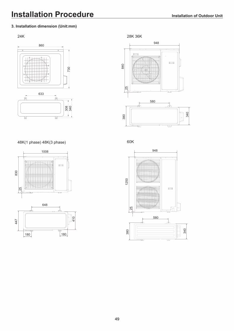
3. Dimension
,
&
%
F
%
YHUJYH060BAS-A-X
33

Model W D H L1 L2 L3
YHUJYH024BAR-A-X 860 308 730 633 113.5 340
YHUJYH024BAR-A-X
34

.&
&
( $
!( &&
!
! -
&
- &
!
( $
!( & &
!
.&
&
!
'+- & & $ & ( # & & "
! & &- &
-
&
! &&
!
$
3
(
!
!!
(
(
! !(
! !( &
5
&&
(
(
(
!
!
!
!
Cassette
35

YHFJZH012BAM-AFX YHFJZH018BAM-AFX YHFJZH024BAR-AFX
36

(mm)
224? 50 ? 200? 47
? 47
? 47
? 47
90
155
D=25
60
300
40
440 D = 47
150
95D = 47
D = 47 D = 47
D=200
114
36
55
90
495598
285
640570
240
700
1580
YHFJZH048BAS-AFX YHFJZH060BAS-AFX
37

# + =-
&
#
"
6
0 <
.
/ 4E3EE
; / . 4 " 6< 0 & #
31 2 3 3 3 2
2 2 3 1 3 3
E
3EE
Low ESP duct
YHEJXH024BAR--GX
Med ESP duct
38

800
1320
830
1200
170 270
250
365
185 25
060 45
1105
4
758
2
15.88
YHGJXH048/60BAR--GX
YHEJXH028/36/48BAR--GX
39

* 1,-. ;
5 -1-;
- &;1;1)= --= 1; = 11=- ?;
9H ;0< -1 - 1;
,-
7 ;7 ;7 1 ;7*&0-- ;)
+1= 1 ;0 11 ;+= 1;
*,-. , 11;
- > I ;- I 1J- > ;
/,0$50/,7 0 ;
+1 ( -1;1= - ;
@=;- =?;
+(H1 1(- ?;.1;- =?;
51;61 1==11=1- ;
$1- 1; - 1;
(1 ;- ;
5 11;= - 11;
@= ;- 1=?;
/1- ;011- ;
9H(;;
- -(- ;- -1 =- ;
61
@+//C5+$0/
%&'
%&'
40
4. Piping and wiring installationoutdoor unit

!"#$
! -;- > - ==;
* -1 ;- ==;
!-11 1 ;, 1< - ; -- ==;
. = 1 11 1I - ;
- 1;, -= 1;5 ---1 ;
0-- 1-> 1;
9-1 ;= ;-= -=- ;
, -&) ;-= - =;
- 1+ 11 ;0 -1 - -- ;
11=> ;11< =< 1-;
9 <1=-1 ;
9-- =11;91- 1- <;
@1 =1 1-< 11;5 - ;
@1= ;- ==;
+1=11;11< ==1=< 1-;
- ;! -;- ===;
@+(G-= -- ;01 ;9< -?=- ;
5 --;
%&'
%&'
0 -& 1) -=-=<1= -1 1 --;
41

!"#$!"#$"()"*&
9 <111011<111 = 1 ;+1( 1= <11- 1;
B =<= 1== ;511 1;
$ (;- = 1- 1;
9 1 1;.< +;&C 1=11=1=(=11= 1 1=1-> ;)11<=<+= 1;,+=1(1;
,1 1=1 -?1;&I;) ==1-=- - ;
+1 11;
$ ==-?1;
$> 11-;51 11 1-1
9 11-;0 11-11;
6<1;+ 1I =1- 11;
- +1;0 11&;;'') 1;
+"
9 -1;81 -;
9 ==== ;0 1 > -;
9 0 1 ===--- ==;01=1& = =- 1;)
@1 =- 1;!1(> -> -1 1 ->
@ -<4K1-11= -;?1- - ;
9 1-1;
$
$
$
42

!"#$+",&#-"!"".#"#%"/
C ;91 1 1==11=1 1;1 1=== -1 1- ;
+"&$
9;+ 1 = -<;
9 -1 ;
=--1 ;
I;
1 ;@ 1==;
$ & =LF0-(* M= ) -;0 1(- ==-1 ;
@11= = --;-=-- 1 1;
9-;@ ;
.-1 1; 1=-= 1I -;
01 - 1;9-I -;.11?;0 11;
.-1;
9 1 1-;911-= --- I 1;
9 -1 ;0- I -- 11=1( 1(1;
9 -1- ;
9 ;
$
$
43

&)+"
0 $ /
C 1 6 1=111 ;:.!1( ;
511! 6 1=111 !1;
1-6> 1-
15- 111 @1-;.-;
15-511. 111 !1;
G/ 51 1 $0-('G ;
0 $ /
C 91 0!G5-1- ;
N . N -1 - ;
1-6> -1 - 1 +;
G0 G11 511;<1;
0 $ /
N . 5N N -1
* *1
.5 5 1
0> @ 011 -';3&'HH);44&4HH)11;
@/15- @1
1511 111
N C ? 51 1
0 $ /
5115- 1511 (- ;
.+#/)
&);N--1 - ;10-7+&');5-<- ;8-11-;&2);* -- 11 ;&);111<=< 1- -;B;
-1 1 ;5-1 '' 11;
#" )"
.1-11 ;/- +&+- ''35);;0 < -+&/ ''35)
';0-
2;0 ''35 +
;0 +
0+ = 1-;
44

&)+"
< . +1
2;. ''=35
;. +
$;
$ <?;, +1 ''= ;&.;3- ;)
+ 1 -(? :;&2O)1= -('! +;&0-(- ? :;;';)0%;$1=;
01 +1 ''1;
- += 1;;;51 1I 11 ;
,?&) 0&),?&) 0-
0-(
0-('!!
!0" 000"!0,&"#-
0%;$1=;
!0"1&)#/
2"#, 03) -
G19&)
6< ,?9+
+ ''
;2
:;'
';3
;44
:;
O
24O
'O
4O
2O
:;
2;'
;
:;3
';
:;
2;
;'
:;
'2;2
2"$0-(' -( 1;0? 1;
G &)
+&0-') ''&0-)
;2
:;'
';3
;44
:;
O
24O
'O
4O
2O
3;
'';
' ;
':;
2 ;
3;
'';
';
'3;
2 ;
;2
:;'
';3
;44
HH
24HH
'HH
4HH
;4
;4
;4
;
:; 2HH ;
9+
6< ,?9*
9*
45

&)+"
. ?> 1 1 I 1> H1=1 ;@111 11= +;6 +> 11;
$<-1 ?1- <;511+111-11 ;
"
/1;/11''35+1;
!
/''351
/.4"# 4"5)6
&6
* + ?1=11 '';!=1=1-1;1> ;+1-1;
"#"#5)*&""
&7$")##$"# 5#$$.$$ 1 1 .;9 11 1 .;
8#$$.8#$$.0$.0*##/55+ > 11 & ); ;
)"))"5#$$."5#$$.0$.0$ . ;= - 1; -=1 -;
5#$.6 > .;+ 1=> ;
0"0"#)$"*5#$$.0$.000) = 11;01 1 ;
9
9
9
9
9
;
';2;
;';
+ (?1&12'E('5='E(:5) 1--''J= 1> =1111-;
"&""+ > 11;&6
--=> +1 1- ;5--11;
@1=1-1;&+1> )&.)4/#"""/
46
.!"'4B2 B
4B&)4B&2) B
+
+
5& )
'B
+
5& )
+
+
+
& )5
+
+
5& )
47
!"#)$"
6&)G<;&')9H1- (;&2)+ ;&)9H 1 ;&) <= 1/01;
&)5 &)G
5
$
+
9#0#
,-11== ;. ;. ;.-1;.- 1;.-;.< ;. -<1;. ;+ ;+ 11 ( ( -;@1 = 1;
00#"7$"."$)$
$)"
@
/
8'
82
8
&,1)
+
+
+
9
22 2
88'82
5 5 5
G< -1=11;
9$)"$
C 1 <-;. 1; 1 21;
+
5
$
0<-
48
!"#)$"9).,6..-
$)"
32
22
24
2
4
'4B2 B
4B&)4B&2) B
'B
'
4
2
24
:4
4
3
4
4 4
'42
4
4
24
2
''
:4
49

!"#)$"
9!0:
9."* 00)5"#)"#
!"#$""""009 1;* <1;*11;B 11> 1;5(11;
+-1I1;0=1 ;@1= -=G1;* 1= ;
9!0##.)
-11 N1& )
=;
C ;44<;
8>
C
:;'<;4
:;<;
8> :;'<;4
!0#
:F;
. G1> &/;)
8> ;2
C;44
8> :;'
C:;
;'(3;'
;4(3;
2';3(2:;:
:3;'(4;
C';3 :;( ;2
9!0)".
C
8>
G
2(-
2(-
2 '
2
'B'4B2 B4B&)4B&2) B
'B'4B2 B
'B'4B2 B
,
,
/
%
4B&)4B&2) B
4B&)4B&2) B
50

!"#)$"
0111 111 ;01> ;11 - =111 &1> );
)2)= =1I-1= 1 1;-1;+11=111 1-1;
511
). ?2 ;2.&2;1'1);
'). ?2 ;.&1'1);+11 ;
2). ? ' 2;.&21'1);+1 ;
!"#)$"@1&8) H1= -11;1&8)<=1&1)1;
07111 E&8()<&1)
"
@ ?1' =5 ;.&;1'1) ; 1;
5 =; =1;
5- 1 1
5-1
8 1 1
0 11?
,I
81(
,
))&"""
5-1
5-1
G
911
-&C)
8 ?
!1 ?
91
-&8> )
/1
N8 N!
G
+11=1;
-58/C11;@11=1111?? ;* 111=<-= 11> ;
51

!"#)$"
9H1=H> 1=I1&)1 1;0I1&)1 1 ;
1 1= ;(1 &) =1;
N ?;+1 1 (;.&(3 !1) ;+ ?1=H8H ;5(';(11=11= 112;
> 1:1;+ => 11;
/11P11=1;1= ;11=11;+11 ?= 11-;
91=> 1;0 11-;
011= => 1> -;
1=-1 ;N ?=1> 11 ;
8#$$.
!055$$..)6$5#$$.0$.0
;
';
2;
;
;
;
3;
6
:,
: ;
8> C
C 1&+)
N &+)
5
N
N
,
8>
C
8>
C
52

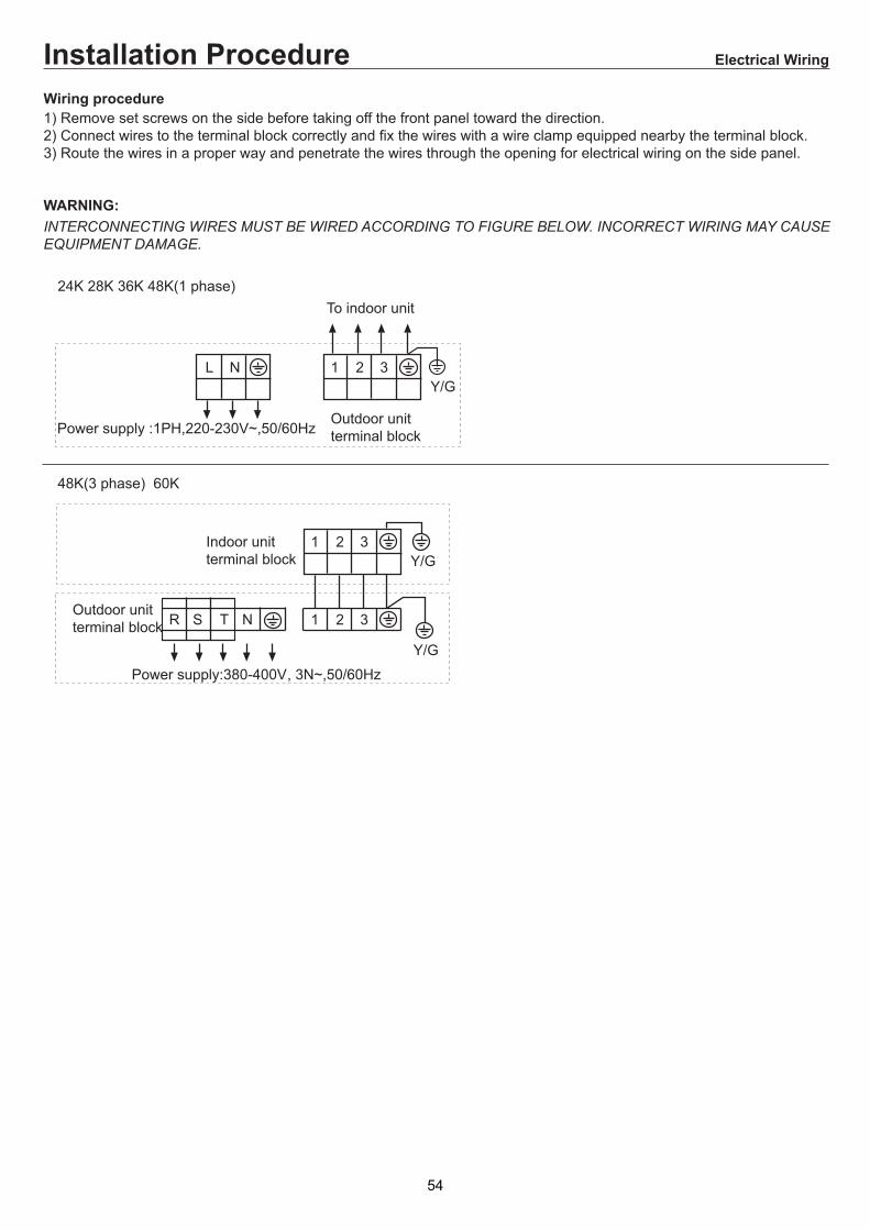
!"#)$" #"#%"
#:0*"$00 )"##*"
!"#$"#"#*"
61 -- ?;9;+- - 1 1;$ -;
,? ;&0'1'K1;)
;'&2+;<=&<&;(0$/GG686505.@6+055$0*6+B6.@6,$56*6G6+B/C+/#6865055//650/,;C$/95//650/,$,0*65.86069*6G6+B/C8/6N80+C65//650/,;
%&'>
-1= - 1> ; <=1-0'+N+5J .5=1-02;+'N+5;* '4B=2 B=4B&)=4B&2)= B=-0 ;2+'N+5;01 1;01 (;+16 ;9 1=1= 1 1;0 (J 2;, <1;0 ;<= 111;+1 ;
0##0*"#4
. ,
&+)
5
-&+)
. ?& )&')
,&+)
61
8 &+)
2 2 ;
2 2 ; 2' 2
'4B2 B4B&)
2 ' ; 'B
G'4B=2 B=4B&)= !/(G2C ;';G4B&2)= B= !3/(GC;';
4B&2) B
53
!"#)$" #"#%"
%"0"#)$")1;')5-<> -;2) - 111;
%&'6 !"#!$ %&%#$' "&(&#!)#*"%&"&
. -7.!=''('2NQ= !?
0
#C ' 28 /
. -724(N=2/Q= !?
#C
' 2
#C ' 2
, 0 /
'B'4B2 B4B&)
4B&2) B
54

: N?7 26627
# & & & "
& & & " &" " & "
& " & & &" % * "- "
& & * +# "' "3 & "# & & &"# &")& " & & " " # # * %"8" " % " ) # &
K-. * L
< 627 7? 26627 >
- * * "-. & " & # *"
A >>627 ?7 6D 26627
!
! !
$ &
.&
& $
! !
$
!
$ $
- &
& &
$
&&
$
.&
&
( $
!( &&
!
! -
&
- &
!
( $
!( & &
!
.&
&
Cassette 2&& >,-+',
! !
55

3
(
!
!!
(
(
! !(
! !( &
5
&&
(
(
(
!
!
!
'+- & & $ & ( # & & "
! & &- &
-
&
! &&
!
$
! !
!
!
2+, ' >&
# # (
#
2&& >,-+',
56

& & *" & * /"
& " 2
% &# * / &" " &# * " && & 9 &"
2&& O&=)
5 ! "
& " & &# &# & # " &# * " *
E 26627 7? 2(77 26
2 -& * 1 -
P*, && -Q
!9 & "
. 1 "
3 & # & 1 #8 " & & &# * &# & &"
& & "
"
! & # " !* " " " & ""/ & "
*# & & " "
2 -& * - &,&+0 O
. & / "
& #
#
. *. *
M"/ N
*# & & " " "/ *"
!9 & " "
# @ &@"
' #
3 #
.&
"
3 /&
M *N
&
O
!
,&
.&
,
# *
2&& >,-+',
57

I *, '+, ))B )& ,*, && &'& * '+, ';JF ?246 >2>24
$ & &" "&"# & & & "" 1 # % "! * & " %& & & "2 0 % " % * & # & & &" & 9 & &" & "&" " 9 & & "
.
"
L 26627 7? 36 (24 >2> &
# # 0 & &" ** : 1+ : $"-+- # & &" . # " " & # &"
2 " & " %& "3 & ( " "
% 3 .
*
*
,& 1
! &
%0
#& 9&
"
1 *
5 ,0
*
" 0 *
" &
& 9 "
!
6&G :
" O "!
P
( "
#1
%&0
! "
(" O(( '"O &"
! O '" O &""!!
" O"
!"O("
" O '"O&"
!"O!"
" ( O '"( O &"
"O"
2&& >,-+',
58
1 * # & & "% && "" & "" / *"" * /& # & " *" & " # & # *"
P= * )& G&,+ &&Q
&" % &# & & & * "&# & & # &"
*, 1,
/# # "# "'# # &"2 &# *"
& & "
& "
5
9 &# & "
. 0 &"
% # . * "
% 9"
) /
P&' *, +,& 1&, * )) Q
.
*
O"
!
- * &
.&
*
& ! "% & & # "
$
/
#
%
%
&&
&
& &
3& &
3 & -
.
&
3 1, -=)
# *## 8O# 1
$
5
5 , '
2&& >,-+',
59

! # "'+ ! # "
$ & & * +-. ", * & & "&"
"
-. "
-. "
2= - -/+
>&0 )-& -&, *1 &+ - -/ &*, &&
),), && =&0 -&' -/
* @
& & @
* @
& @
& @
& & * &@
* &@
1 @
! * & @
& & &&& @
2 & # "
% * & &"
- * "
- * "
# * & "
# * & "
% & & "
# * & "
% * &"
& &&"
5 & # & &"
R 3224 S>
M 3224
! " & & "2 *"3 &# & & "! & * 0 "! # * *". # # & "& / # & !# # & #& !" "3 " # # * "2 &# / "
%
/ !
5&
/
$
" &!
( *& & B , 1&, =&0 -= ;
'+ # & "
. 1 3
'
QR
3245
2&& >,-+',
60

1=00 ;- ;
# 4 +0 =?;
$
.
!
%
9
;
&!$&1'&!$#'!&!'- - ))+ == J;)$+3 ;3 ;)%+ ;)+: < ;)+ 0;)!+ 0;)6+3; ;- ;
(
'
!
4 65 - --66--64 -;+!46+0 ;
-* *0;-* 8)+1 ;)$+/;)%+C ;)+-> ;;0=;)+;)!+D0 0;)6+C*;)4+1= ;.8)+. =K;)$+" K ;)%+C ;3I== ;0 = = 0===0 ;-> = 0;
Covertable type(12K/18K/24K) ! #
+7 ===0 ; + 0 ;
"-* > 0;
%
%
;
;
9
0
! 5 +
9*: -66+9,: +9.:! *< - / 55- +
3;@> ;
!&&!'#&
2
-
/)9;/+
:
"
1
1 0
1
"!$)
&!')
"!$)
&!')
61

/);$+;= 0);+;
,+!
A )+ ;);!+
:
:
C0
:
:
):+
! #
2 <;
)3 ;/;
+(''''&0#*+
/;3;;
- 5
##!$!''!&!&&!'
A=0;= ;
A
/
!;
55 $;
!;
$;
!;
%
;
6
%;
3;);$+
A
6
!
A=6; ;A =;%;
:)9+ :)+
;
;$
;%
;
;
;!
62
: ;"- ;);4+
, 0 ;);6+
;6 '= ' '
-;
:
;4
:
>+!!$&0#@=)+;);5+
A.
:
:
$
5;5
*+ /;);+
,+ 6 6
A=4; ;);+
; ;
; );+
;%
;$
=0;);%+
!
6
$;6
A!
;
! #
A= $;6;";);$+
&!')
&!')
63

.+!6
=;);+
// ,
2+!
,)+,)9+
<;; "<
4%
-0 ;);!+C= 0<;
, ,
/;);$+= 0;);+A )+ ;);!+, 0 ;);6+
3+!
C22D
1
,),+
I3
1 .
I3
:
! #
;
;- ;,
;!
;6
A;/ I3;);4+
;4
;
-
:
64

-6 +( 9 (46:9(+:)+. * = $<;)$+@=)+;)%+@= ;)+/0= 0 ;
>+( 9(+>:)+. * = <;)$+@=)+;)%+@ = 0 ;)+1 = ;
/
$
9
+
3
/
A
/
A
/
>+
- ==;@IA*=;;=1I. ;
(? 6 -
.
&!"!!$
'&!$&1#!#!$
*+( )+. ;)$+" = ;)%+ 3 =;)+.M9M);+ 0;
&6*
1 /
9
/)$$+
9)$+
,+>300 ;, ;
9>
: :-)+
;O;$!;%) M+
E
;O$;$
$;6) $M+
5;$)% 4M+
;44) 4M+
9>
E
! #
2D C2
7<0
9
A9
;
9> ;O;$
!;%) M+
E 5;$)% 4M+
1
$D
4D
$D
-
1<
65

)+3 0 ;A 0 =0;)$+A =0;)%+3@ =;;
)+-0 0;)$+@ 0;)%+3 ;-0 %;)+100;)+ 0;
;7 0 ;.0;0 ;-0 ;) =0 ;+-0 ;
! #
"
)$+1 <;
)+A;;$;1 ;%;. 0;;;;;
)%+<;
,
7<;
7<
, <;
)+<;
7<
:;=<;
7<
;
)C+ $)9+ %).+& E
& E
2
$ %
&!')
&!')
&!')
"!$)
&!')
66

'&&1'@#&&1!&=$!
*+ 59:)+. <;30<;3> ;
.)+
)$+')+ ;
! #
%)+. ;30<
.+ +
')+ ;
,+ 59:
)$+0;3 ;
&-*+!
N:0N: 0NN
,+'
0 NA= N0N
-
7< 8)+ / = = J == ;)$+-= ;)%+E ;
67

#!&#%(#!&'(!#!(
"!&
#!(8 ;8 ; 11 = 1 ;
1 ;
'+ J;'(+4 = ;'.+8 < '+ 1;'+ 1;'!+4=;NN;'9+
(!*(!##!(
4;@> ;
Covertable type(28K/36K/48K/60K)! '
$ $ 1
*
/
C833@C4
P.N')+ P!N'+ P;N'+
/
C833@C4
P.N')+ P!N'+ P;N'+
/
*
3
-
0'7;0+
8
"
2
2 1
2
!#'!!(
68

!#!&#%!((!#
! $
=$
01$ < <
'+-'(+'.+0'+'+4 ;4 *=NN;
21 8
* ) 0 *
/36.
/
0 < .;
/3!
/
0 < .;
0 .
. .
C833@C4'432K5A+
8'0> +
.
0-'+ 0-'7+-
! '
87> E
<
< ' +
:;( :; .
:;( ;)) . (()D.!D
)D!D
69

31 8
! 8 '+81 ;C 1;'(+=1 N,N' +1* ; !"#$%&'(%)&%%&*%+!,
61!
'+7 ' += ;'(+ 1* N,N ; ;
/
0 -' +
'31+0 ,' +
'+8( *;4 ;4 1;'(+=10 -, ; !"#$%&'(%)&%%&*%+!,
C '31+
0 ,' +
C '31+
71! -= 1 '+ = ;- =1;0 1;
C1'+
C1'+
C
/
/ '+
/ '+
/ '+
/ '+
* )
= ; =1 ;
#!(
/
A
A *= ;81 1 ;
E '(+
'4+
A
/
A
/
A <1= 1;
.A =< <!= ;
4 ;
6.0
<!
! '
70

!#!&#%!%(
' +;@11'K2(+' .)+8 = 1 ;A= ;8;-1 ')+;
,-8
0 !;';(+
>0?!
8'41;7 );+
'+8 '+
8
C
8
8
! '
E338 ,-8
/ ?;
'+
/K4
K4< ;
>2?"
71

#!"!!&
'+/ * = !N'(+<;'(+@='+;'.+@= ;'+01= 1 ;
@1* '+/ * = . )N'+<;'(+@='+;'.+@ = 1 ;'+2 = ;
1* > *)8?
0
A4
0
A
1
7
0
!
N'(
+
@1
0
.
)N'
+
- =;@KA*=;;=2K/ ;
*A 8 $ /
! '
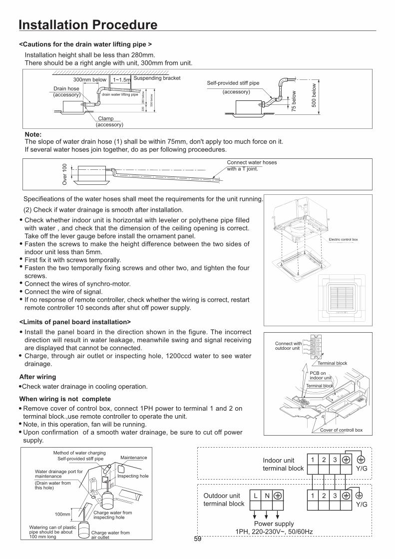
#!( ;5 1 ;/1;1 ;-1 ; =1 ;-1 ;
=$
$
'+;'(+2;'.+/ 1;'+;'+;
()D.!D
)D!D
0? ;'4((Q+;
.
2 0
'-+
/
3 1'-+
2 ?
' +'(+
. !;
0'-+
5
7 '-+
. ; ( .
4@ =;
72

4 1 ;A 1 =1;A =1;
#!(
*%!!#B
;3 ; *= ;
#!(
A'+= ' +;A'+= J 11 =;
(; '+; *=;
.;/ ;
8
*
'+
"!&4*;-1 1;@ 1;4 ;-1 .;211; 1;
! ' "$
;01=;;
()D.!D)D!D
2 12"=((*(.KR= !"?
3
$ E
( .
$ E ( .7 C 3
2 1.)*K=.CR= !"?
$ E
0 4 C ( .
$ E ( .
$ E
73

#$01!
O81O8 1OO
21(
1 OA== O1O
$
5< 6'+0== J === ;'(+-= ;'.+E ;
74
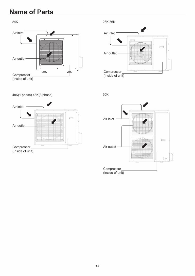
(
! (
# + =-
!
@$5 @9 >:9 9 9 9>:9@9 9 9 >:9 >#5J 9 9@ >:99 $5 >: 5+ ->75 +A -95 9>#@ 9>/ $ 9 >
. ;>"9 9!L4, 9 5>: %>>.99J 9>"9$>> 9B 9>#@ @$9>> 5>>49@59 95>
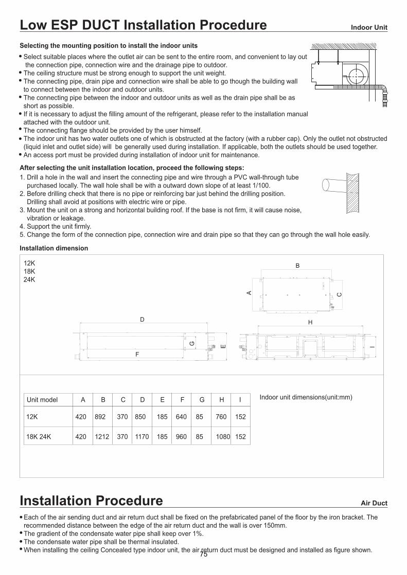
Low ESP DUCT ! '
<9 ?5>:9 $>:9$S>: >89945 @ 99 >
! '
&
#
"
6
0 <
.
/ 4
E3EE
; / . 4 " < 6 0 & #
31 2 3 3 3 2
2 2 3 1 3 3
E
3EE
75

12!
: @ 3>: ,9 @$>/69 @5I J ?5A >
# ? :
/ 5
:, 5
82!
;$ @ 69 >
42#(
/,9 5 >69 5 @$5 9 5?>65 $>/69 >
#
/ /
9 5 9 5
$
$
#(
/ 5/
/
9
"
:
/
:, 5
3?
3
3
3
/
;
89 @ @>: >>899 @ @>: >>
>+ 9->+ 9-
49
/ 5
/
. 9
?;
: ;
?
/ 9
/ 5
! '
76

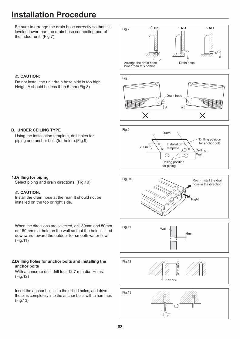
" ,
: >:9A 9$9>8>3
'
#!$
E
! ;3 +@-+ 9?>1@B5->:9$99 9 >
" /A 5 >
/:@ >
$ ;9@ 9>
(;9 95>
+ 6 9 : >/$@J $
E 0 !
6
#
! '
A
.
&99
9
#@999@$ 5>:999 9 9>/@$599>:99 99 >
/ :9 > >
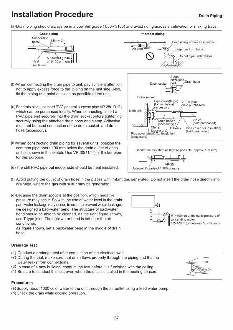
!B+ =-
(:9 >:9 9 9> ;7$9 99 >: 9 >
4 9>
'(! ?B+:!->
0 A
! '
>2
>33
>
1>
)(8$ @$ $$ ><599 5>
1> >E
497>">+-
#9A +D,-
>
1>
>2
>33
>3+>9,-
>+>9,-
1>+>9,-
23>+3>9,-
3E
77

: +/$-
#
5
69
"5 95>: >!5B# >8 5 9@9 >
: 99 $4: >
'
'
#!$
! ' $))
&
! (
7$$ >
4999>
4 9A $5>" 99@A 9 $9>
#5@ $9>#5 9>
>(
: >: $9>:+9%->: 5@ >:B9>#9@ $$5>T$$5>49 999 >:5?>
' (
9!L4L!+-
6!<$2
!
#
+
"B=+%K-!L4: J 9,99!L4>
( " 9 @9 99$>
8
7
"+ 5 -
L!
:9+>-
"$%
5
>U
# + 5 -"$%
! '
& &
5 # 9!L4
78

"!&
&$%*$!?!@?$#+:;D766<<4:#4!78</:4#4;#:.</E<7!78< 7;4<.<67</E#D0/D(<<4:#447DD<4:#7D >07;D"47DD<4:#7D ; :.<47!<:<".<67</E#D0#D<L7:/0<47DD<4:#7D >
'
<9 55 B>">/5 5 9 9>; 5>
"
9 5 @ 5>
! '
+D- +- +4-(%0
(%0
7
#
79

8
?,>8>/>" ?884> #8, 8/8,@8>/8>" ?884> J A 888#8-A 4# >24 8>
%$
3 3 $!%5$$%'$!%>9 ###4 > @ 4 >
"!'
# 0 8 @4>84>
33 6 :
4>78?48>" @ 884 > 8 8> @4 - > #- .# 4.S>,78 8 4#@4 #8 >/388#88>
6
!
3
3 %%%
>
>>
>
>
>
>
>
!
#7
E,/ .E%E.E,/
E,/.E%E.E,/
Med ESP DUCT ! #
<A 2
=> >..
80

(:! 5? 8>"A @ @>!44 88>
7 8@J 88>
A 8
,/1J -# 8#48>J #8#>
,/:J #4@ 8 4 >
$ 6 ,78 >/
9 84>7 448 8@>@8#?>
L3
8 4
7#
T,T>K/
08884>
&88
8
(
7
,8/ &80
7
3
3
3?
0
(
7
0
(
7
0 7
0
9:#
:7 6
P3U
1
0
3
&88
38B
38T
38T
&88
38B
! ) 5
6:16 :8 >
&88
&-&- 8
"
3
! 1,/ 0,/ 3,/
!
!,/),/ 5,/
=.
%
=
%.
.
%=
%
%.
E,/
.E%E.E,/
! #
81

#
!8 48,$T$/#8#8>
78 @4 4?8 >1@?8 >
5@ L38 L -,">!>K/ 4>78@ L3 488 4 8>1# ,4/>
!8!
!
L -J, / #,8/
N O,4/
L -, /
#N O, /
!,4/
#,/N O,4/
3,4/ 1
!
E
1#8#
1#
!3 '
>T
&
18$
,/
,/
L -
#8,?>/
18$
8#!
*L -,< /
,? /
=T
1#88 84 >!8 848>
,/
,/
,/
,8/
,/
7 88# @ >:L -,$K/ >
9 L3 >!###>
98# #8@?8@#8# 8888>78@88@-A 4# 8 4 #>9@88#>
#! #
82

!
3 ? 8@ >
10 -@--4 >
,/ ->,/ ->
<8;> 8 > >,3 8>/:>> 8>3 88>
5=
:&"88>: ? >, >/
6:=+ :,:? >
2?0?0?
)? 8
58> 58>
$
3 8>! 8@ 4 88>" 8@ 8>0 # 8>
1
!8
!
#8> >
" 4T 4>,"8>/
#?J>
# 4 8 8 >38>
0@#?J#>9@84 84>
,/,/
,/
,/
,/
,/
38
&
,/
1
,6/
0 ,6 /
&
,/,/
,/0
1
3
#
! #
! #
83

"!'
'%&0%!B!CB%$1
9:D655)<)39"3 67)193"3:"90)1E)6 67)6:3)0)56)1E"D21D()<)39"336DD)39"6D>26:D!36DD)39"6D:90)36 <)9)!0)56)1E"D2<"D)L6<912)36DD)39"6D>
7
# )8 44 B>!>14 4 8 8>: 4>
B >,98S#8>/
" 8 4 @ 4>
4; &@-LT@$%&B
6
" ($2
($2 < D
"
,1/
3
6# 4,1/
B, /,/
,1/
)8
< ,1/
%>
E,/.E%E.E,/
! #
84

*>* . ?
$#
(( #!$.##$&#!$28 $$$3 > @ 3 >
"!&
.: 9:85:/"8: :#D 8928#5D 2/:49<<(.:45:.:)#DD#D)#D 8/<</8#5D>4/#<9:8545<<568: : #D 8928#5D 259<"2/9 : :#59 #D*9(5":/8@:C9#!:D8/<49D28#5D/D"%5!5!:8("//):>
23$ >.$7 @$7>6$7$7@ 3$ 7 7>
8 7A 7 I>! >87>67 @ 3 >,#?@-! 7>87 ,7 ->8 @ @3$>8$ 7 3$>,:$ 3@ 7$7@ >-8 7@7># 7>27 3>#@7 >
,&?&-
5$ 5$1
/
/
27
27
5$
5$
12#( >;((?
82!. 2>!) ?.@,7@7-,@ - @@33 >2 77>3777$$7$>4@ >
!
& =
=1
"
9
!High ESP DUCT Installation Procedure
85

42+ /97 >,9-#7 @?7@ 7 @7@ 7 37@ 37 >.77@J 77>
77
00 7
#
2
52!4? 7>#A @ @>"33 77>
6 7@J 77>
62@ )
,-/J 0$ 7$37>J $7$>
,-9J $3@ 7 3 >
!L2
!7 3
6$
T,T>K-
.7773>
77
7
!!'
86
,7-
L!0
$7,?>-
/7%
6 77$ @ >9L!0,%K- >
,-
,-8!L2 >
,- /$ 7 77>"37@7 37>
. @7$ 3 > $@73 >#$7@7>8 >/77 @ 83J>8>/7 @>
#
2 7>" 7@ 3 77># 7@ 7>. $ 7>
' 3 7 7 >27>
G
7G%,T-
"
7"
"
L!0J, -
!$,7-P Q,3-
L!0, -
!$P Q, -
",3-
!$,-P Q,3-
2,3-
/
4@ !L27 L!0,#>">K- 3>67@!L2 377 3 7>/$ ,3->
,-
"7 37,%T%-$7$7>
67 @3 3?7 >/@?7 >
&
>T
/7%
,-
"
E
/$7$
/$
!(
,-
,-,-
,-,-
,-,-
' !'
87

:77/
L
/#
$3,7-
7J
/$ J
/
27
/
27
/ 7
! 0$7 @ @77 77 >2 777 @77 7>
#>( /?
)?.?.?877$3 ;> 7 > >9 7 77 >! @7>
(((A
! 7 7 !%@ ?@;
D;!%G>/7%#(
?
/
:A , 7-
./
/
/
&%,%-
"
%,%- ?&,?-?1,?-
/$
E,7-&E
/.
7
./
?
/7,-
2 7!@!%
:T77
2 !2 !%
2 !%
&,-@@,-
?&?1???=?1??=?
#/$ %,%-
A
",?-
@@&
??1
@,-@,-@@@@@&@,-
??=?&?&?=??1??1?
#/$ %,%-
A
",?-
!'
88

#)(
0 07 >,3 7-8 7>8 >8077 3 >8 $7 7>
#:((
" 7 >8 7 @7 @ 3>83 >4 @$77 @ 37>/@ 7$>, 7-3?7 ,?;3 2@ 2-@3$>/3377@7 @ 7$ ?@7?7$@77>
//
"
77
9?
/77
#?
!'
89
87@A 3 @ @3 7>8 77>6 7 @7 @ A 7>6 @ 7>907@>78#A >8737 77>2@ @7 >53 J >
!7
8A
!J2
B ,3-,9 J-
2
,3-,A -
,7- ,3-
)<A
>T>
>&T1>
=T11D>,T=7>-
&T=D>,&T==7>-
87A 22/,-
>1T>1=T&D>,11T7>-
1>
>
1>
>T>
/1>
'
8#
<A ) :?9
/ /
""
L!!L2
!'
90

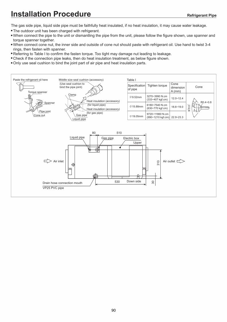
"!&
&$%*$!B!CB$#+89D544:<:28#2!56:/82#29#8.:/E:5!56: 592:.:45:/E#D)/D(:<:28#225DD:28#5D >)59D"25DD:28#5D 9 8.:25!<:8:".:45:/E#D)<#D:L5<8/):25DD:28#5D >
0
' :7 33 B>">/3 3 7 7>9 3>
B >,87U$7>-
E,7-&E
#
!
,/-
2
5$ 3,/-
! B, -,-
,/-
:7
< ,/-
>
"
7 3 @ 3>
"
5
#
! 3;0L@DT@%&B(%)
(%)
8 D
!'
91

5.1. 1.
5. PCB photo,Wiring diagram and function description
Outdoor PCB photo
5.1 Outdoor unit
YHUJYH024BAR-A-X PCB(0011800241C)
92

YHUJYH024BAR-A-X power module
YHUJYH028/36BAR-A-X power module
93

YHUJYH028/36BAR-A-X filter board
YHUJYH028/36/48BAR-A-X YHUJYH048BAS-A-X YHUJYH060BAS-A-X PCB(0151800054A)
94

YHUJYH048BAS-A-X YHUJYH060BAS-A-X power module
YHUJYH048BAS-A-X YHUJYH060BAS-A-X filter board
95

YHUJYH048BAR-A-X filter board
YHUJYH048BAR-A-X power module
96

5.1.2. Wiring diagram
OU
TDO
OR
PC
B
POW
ER M
OD
ULE
YHUJYH024BAR-A-X
97

YHUJYH028/36BAR-A-X
PTC
SW
5S
W4
SW
2
LPH
P
Mod
ule_
CO
M
M
LED
1
DC
FA
NM
OTO
R
250
VAC
T6.
3AFU
SE
AC
N AC
L
ON 12
34 H
EAT
ER
LN
Pow
er
SW
6
W
W
BB
WUR
V
WB
PM
V
M
ON
CO
MP
RE
SS
OR
D
efin
ition
of S
W7
SW
7-1
SW7-
2 SW
7-3S
W7-
4C
OM
MC
OM
MU
NIC
AU
NIC
ATIO
N C
TIO
N C
HO
OS
EH
OO
SE
ON
OFF
ON
OFF
FO
R M
OD
EL:
FO
R M
OD
EL:
1U28
HS
1ER
A1U
28H
S1E
RA
1U36
H1U
36H
S1E
RA
S1E
RA
Y/G
OR
: Ora
nge
B
: Bla
ck
B
L:B
lue
Y
/G: Y
ello
w/G
reen
R: R
ed
W:w
hite
Tc
m: C
onde
nsin
g Te
mp.
Sen
sor
Ts: C
ompr
esso
r Suc
tion
Tem
p. S
enso
rTa
: Am
bien
t Tem
p. S
enso
rTd
: Com
pres
sor D
isch
arge
Tem
p. S
enso
rTe
: Def
rost
ing
Tem
p. S
enso
rTm
: Mod
ule
Tem
p. S
enso
r
T25A
250
VAC
FUS
E
Y/G
12
34
56
78
ON
W
W
B
B
Reactor CN
5
CN
7
CN
6
Tm
B W
4-W
AYVA
LVE
SW
1
ON 12
34
SW
7
Tcm
TsTd
TeTa
SW
3
1W
23S
IG
BR
Y/G
To in
door
uni
t
OR
OR
R
OFF
ON
OFF
ON
CO
MM
UN
ICAT
ION
CH
OO
SE
FO
R M
OD
EL:
AU
482A
IER
AA
U48
NA
IER
AA
U60
NA
IER
A
Def
initi
on
Def
initi
on o
f SW
6S
W1
SW
2S
W3
SW
4
OFF
ON
ON
OFF
OFF
OFF ON
OFF
OFF
OFF
OFF
OFF
OFF
OFF
OFF
OFF
OFF
OFF
OFF
Sta
te w
hen
out o
f
fact
ory
Nor
mal
oper
atin
g
Com
puls
ive
Hea
ting
Com
puls
ive
Coo
ling
Def
rost
tim
ing
Rat
ed O
pera
ting
Def
initi
on o
f SW
1S
W1-
1S
W1-
2S
W1-
3S
W1-
4S
W1-
5S
W1-
6S
W1-
7S
W1-
8
MO
DE
L 1U
28H
S1ER
A1U
36H
S1ER
A
OFF
OFF
ON
ON
ON
ON
ON
OFF
ON
ON
OFF
D
efin
ition
OFF
ON
ON
ON
ON
Not
e SW
1-1&
SW
1-2
are
used
to c
hoos
e ca
paci
ty;S
W1-
3 is
cho
ose
for
1.po
wer
mod
ule
;SW
1-4
is f
or fa
n m
otor
,ON
--D
C fa
n O
FF--
AC
fan;
SW
1-5
is f
or F
AN
qua
ntity
,ON
--si
ngle
OFF
-dou
ble;
SW
1-6
is
for c
omm
unic
atio
n ,O
N--
new
OFF
--ol
d;S
W1-
7 is
for p
ower
so
urce
,ON
--si
ngle
pha
seO
FF--
thre
e ph
ase;
SW
1-8
is fo
r qui
et
oper
atio
n,O
N--
avai
labl
eO
FF-u
nava
ilabl
e2.
Onc
e ou
t of f
acto
ry
do n
ot c
hang
e th
e sw
itche
s
LED
2
BL
OR
OR
OU
TDO
OR
PC
B
POW
ER M
OD
ULE
FILTE
R
98
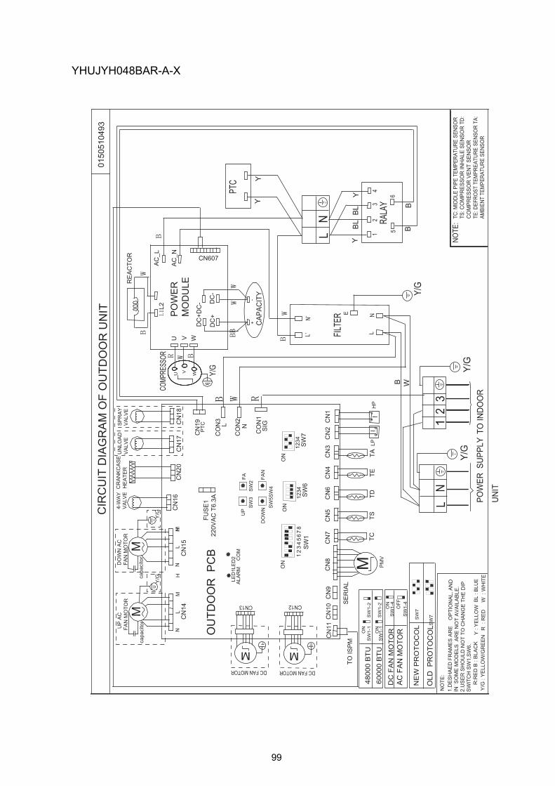
LED
1LE
D2
CN
19
CO
N1
WU
COMP
RESS
OR
V
M
2
20V
AC
T6.
3AFU
SE
1
1.D
ES
HA
ED
FR
AM
ES
AR
E
OP
TIO
NA
L, A
ND
IN
SO
ME
MO
DE
LS A
RE
NO
T A
VA
ILA
BLE
.2.
US
ER
SH
OU
LD N
OT
TO C
HA
NG
E T
HE
DIP
S
WIT
CH
SW
1,S
W6.
NO
TE:
CN
8
PM
V
PTC SIG
CO
N2
N
SW
5SW
4SW
2S
W3
FA
R:R
ED
B :
BLA
CK
R
: R
ED
W
: W
HIT
EY
/G :
YE
LLO
W/G
RE
EN
CO
N3
L
U V W
AC
_L
AC
_N CN607
BL
: BLU
E
CN
11
TO IS
PM
CN
1
LNE
L’N’
HP
LPC
N2
CN
9C
N10
CN
3C
N4
CN
6C
N5
CN
7
TC
TS
T
D
TE
T
A
SE
RIA
L
CN12
DC FAN MOTOR
M
CN13
DC FAN MOTOR
M
SW
6
ON
1234
FAN
UP
DO
WN
CO
MA
LAR
M
0150
5104
93C
IRC
UIT
DIA
GR
AM
OF
OU
TDO
OR
UN
IT
L1
2
Y/G
POW
ER S
UPP
LY T
O IN
DO
OR
UN
IT
Y/G
Y/G
FILTE
R
3
ON
SW
1-1
SW
1-2
4800
0 B
TU60
000
BTU
ON
SW
1-1
SW
1-2
ON
SW
1-4
DC
FA
N M
OTO
RA
C F
AN
MO
TOR
OFF
SW
1-4
TC: M
IDDL
E PI
PE T
EMPE
RATU
RE S
ENSO
R TS
: CO
MPR
ESSO
R IN
HAL
E SE
NSO
R T
D:
CO
MPR
ESSO
R V
ENT
SEN
SOR
TE: D
EFRO
ST T
EMPR
EATU
RE S
ENSO
R TA
: AM
BIEN
T TE
MPE
RATU
RE S
ENSO
R
NOTE
:
B
M
CR
AN
KC
AS
E H
EA
TER
4-W
AY
V
ALV
ED
OW
N A
C
FAN
MO
TOR
CN
20N
LM
UN
LOA
DV
ALV
E
CN
16H
CN
15C
N17
capa
cito
rM
UP
AC
FA
N M
OTO
R
NL
MH
CN
14
capa
cito
r
SP
RA
Y
VA
LVE
CN
18
Y/G
Y/G
ON
SW
11
23
45
67
8
DC
-
L2
DC
+DC
-
DC
+
CAP
ACIT
Y
RE
AC
TOR
SW
7
ON
1234
W
N
SW
7N
EW
PR
OTO
CO
L
OLD
PR
OTO
CO
LSW
7
+-
L N
12
34
Y
BL
BL
Y
B56
B
PTC
YY
RALA
Y
Y/G
Y :
YE
LLO
W
YHUJYH048BAR-A-X
OU
TDO
OR
PC
B
POW
ER
MO
DU
LE
99

LED
1LE
D2
CN
19
CO
N1
U
W
CO
MP
RE
SS
OR
V
M
220
VA
C T
6.3A
FUS
E1
2.U
SE
R S
HO
ULD
NO
T TO
CH
AN
GE
TH
E D
IP
SW
ITC
H S
W1,
SW
6.
1.D
ES
HA
ED
FR
AM
ES
AR
E O
PTI
ON
AL,
AN
D IN
SO
ME
MO
DE
LS A
RE
NO
T A
VA
ILA
BLE
.
NO
TE:
CN
8
PM
V
PTC SIG
CO
N2
N
SW
5S
W4
SW
2S
W3
FA
B :
BLA
CK
R
: R
ED
R:R
ED
W :
WH
ITE
Y/G
: Y
ELL
OW
/GR
EE
N
CO
N3 L
WV
UR
ST
SC
P1
SC
P2
SC
NC
N60
7
BL
: B
LUE
CN
11
TO IS
PM
B
RW
B
CN
1
R
W
L1 L2 L3 N E
L1’
L2’
L3’
N’
E’
HP
LP
CN
2C
N9
CN
10C
N3
CN
4C
N6
CN
5C
N7
TC
TS
T
D
T
E
T
A
SE
RIA
L
CN12
DC FAN MOTOR
M
CN13
DC FAN MOTOR
M
SW
6
ON
43
21
FAN
UP
DO
WN
CO
MA
LAR
M
RW
0150
5090
27C
IRC
UIT
DIA
GR
AM
OF
OU
TDO
OR
UN
IT
RS
T1
2
POW
ER S
UPP
LYTO
IND
OO
R U
NIT
Y/G
Y/G
FILT
ER
3
ON
SW
1-1
SW
1-2
4800
0 B
TU60
000
BTU
ON
SW
1-1
SW
1-2
ON
SW
1-4
DC
FA
N M
OTO
RA
C F
AN
MO
TOR
ON
SW
1-4
TC: M
IDDL
E PI
PE T
EMPE
RATU
RE S
ENSO
RTS
: CO
MPR
ESSO
R IN
HAL
E SE
NSO
RTD
: CO
MPR
ESSO
R V
ENT
SEN
SOR
TE: D
EFRO
ST T
EMPR
EATU
RE S
ENSO
RTA
: AM
BIEN
T TE
MPE
RATU
RE S
ENSO
R
NOTE
:
B
M
CR
AN
KC
AS
E H
EA
TER
4-W
AY
V
ALV
ED
OW
N A
C
FAN
MO
TOR
CN
20N
LM
UN
LOA
DV
ALV
E
CN
16H
CN
15C
N17
capa
cito
rM
UP
AC
FA
N M
OTO
R
NL
MH
CN
14
capa
cito
r
SP
RA
Y
VA
LVE
CN
18
Y/G
Y/G
ON
SW
11
23
45
67
8
DC
-L1
L2D
C+
PN
DC
-D
C1-
DC
2-D
C+
DC
1+D
C2+
CAP
ACIT
Y RE
AC
TOR
SW
7
ON
43
21
BL
N
W W W
SW
7N
EW
PR
OTO
CO
L
OLD
PR
OTO
CO
LS
W7
WW
W
WW
BB
BW
ON
SW
1-5
SIG
NLE
FA
N
DO
UB
LE F
AN
ON
SW
1-5
NE
W P
RO
TOC
OL
OLD
PR
OTO
CO
LO
NS
W1-
6
ON
SW
1-6
YHUJYH048BAS-A-X YHUJYH060BAS-A-X
POW
ER
MO
DU
LE
OU
TDO
OR
PC
B
100

stra
iner
com
pres
sor
4-wa
y st
op
valve
2-wa
y st
op v
alve
(liqu
id s
ide)
3-wa
y st
op
valve
(gas
sid
e)
cond
ense
r
evap
orat
or
pipe
coi
l te
mp.
sens
or
heat
ing
cool
ing
disc
harg
e te
mp.
sens
or
stra
iner
ambi
ent
tem
p.se
nsor
stra
iner
elec
troni
c ex
pans
ion
valve
3. Main control functions3.1 Refrigerant diagram
YHUJYH024BAR-A-X
101

CO
OLI
NG
HE
ATI
NG
high
pre
ssur
e sw
itch
low
pre
ssur
e sw
itch
EEV
filte
r
sunc
tion
tem
p.se
nsor
T
disc
harg
ing
tem
p.se
nsor
Td
coil
tem
p.se
nsor
T
cond
enso
r te
mp.
sens
orT
evap
orat
or
cond
ense
r
3-w
ay s
top
valv
e(ga
s si
de)
3-w
ay s
top
valv
e(liq
uid
side
)
4-w
ay s
top
valv
e
gas-
liqui
d se
gera
tor
filte
r
defro
stin
g te
mp.
sens
orT
heat
er
ambi
ent t
emp.
sens
orTai
com
pres
sor
ambi
ent t
emp.
sens
orTai
YHUJYH028BAR-A-X YHUJYH036BAR-A-X
102

CO
OLIN
GH
EA
TING
high pressure
switch
low
pressure sw
itch
EE
VFILTER
service valve
service valve
suction sensor
Ts
discharging sensor T
indoor coil
sensorT
middle sensor of
condenserT
evaporator
condensor
3-w
ay stop valve
(gas
side)
3-w
ay stop valve(liquid side)
4-W
AY
VA
LVE
compressor
gas-liquid segerator
FILTER
defrosting sensorT
capillary
heater
indoor am
bient sensorTai
YHUJYH048BAR-A-X YHUJYH048BAS-A-X
103

CO
OLIN
GH
EA
TING
high pressure
switch
low
pressure sw
itch
EE
VFILTER
service valve
service valve
suction sensor
Ts
discharging sensor T
indoor coil
sensorT
middle sensor of
condenserT
evaporator
condensor
3-w
ay stop valve
(gas
side)
3-w
ay stop valve(liquid side)
4-W
AY
VA
LVE
compressor
gas-liquid segerator
FILTER
defrosting sensorT
capillary
heater
indoor am
bient sensorTai
YHUJYH060BAS-A-X
104

SW1-1 SW1-2 SW1-3 SW1-4 SW1-5 SW1-6 SW1-7 SW1-8 Description0 0 ---- ---- ---- ---- ---- ---- 28K outdoor unit0 1 ---- ---- ---- ---- ---- ---- 36K outdoor unit1 0 ---- ---- ---- ---- ---- ---- 48K outdoor unit1 1 ---- ---- ---- ---- ---- ---- 60K outdoor unit
---- ---- 1 ---- ---- ---- ---- ---- power module choose1---- ---- 0 ---- ---- ---- ---- ---- power module choose2---- ---- ---- 1 ---- ---- ---- ---- DC fan motor---- ---- ---- 0 ---- ---- ---- ---- AC fan motor---- ---- ---- ---- 1 ---- ---- ---- single fan---- ---- ---- ---- 0 ---- ---- ---- double fan---- ---- ---- ---- ---- 1 ---- ---- new communication protocol
---- ---- ---- ---- ---- 0 ---- ---- ld communication protocol
---- ---- ---- ---- ---- ---- 1 ---- 1 phase---- ---- ---- ---- ---- ---- 0 ---- 3 phase---- ---- ---- ---- ---- ---- ---- 1 mute sounds mode valid---- ---- ---- ---- ---- ---- ---- 0 mute sounds mode invalid
PCB 0151800054A dip switch setting
SW6-1 SW6-2 SW6-3 SW6-4 Description0 ---- ---- ---- normalcondition running(default)1 ---- ---- ---- rated condition running
---- 0 ---- ---- normal defrosting(default)---- 1 ---- ---- compulsory defrosting---- ---- 0 ---- normal cooling(default)---- ---- 1 ---- compulsory cooling---- ---- ---- 0 normal heating(default)---- ---- ---- 1 compulsory heating
YHUJYH028BAR-A-X YHUJYH036BAR-A-X YHUJYH048BAR-A-XYHUJYH048BAS-A-X YHUJYH060BAS-A-X
105

3.2 Outdoor frequency control 3.2.1 Compressor running frequency range: 30-91RPS. 3.3 Electronic expansion valve (EEV) control: 3.3.1 Electronic characteristic: Max. open angle 500 Pulse Driving speed PPS 3.3.2 Initialization of EEV EEV driving speed: open direction: 32MS; close direction: 32MS 3.3.3 Open angle limit of EEV
Unit stop Adjustableupper limit
Cool/dry 250(E) 480(E) heat 250(E) 480(E)
3.3.4 6、Standard open angle control In Cool/Dry mode, standard open angle: outdoor ambient temp.≥22, 260pulse (E)
Outdoor ambient temp.≤22, 210pulse (E) In heat mode, standard open angle: outdoor ambient temp.≥6, 240pulses (E)
Outdoor ambient temp. ≤6, 160pulse (E) 3.3.5 When discharging temp. Td is too high or too low, modify the EEV angle
mode Modification process Max.modification
Cooling If TD>106 degree and -1 degree /2 minutes, open angle keeps between 106-50 .
-3
Cooling If TD<50 degree and +1 degree /2 minutes, open angle keeps between 50-106.
+3
Heating If TD>100 degree and -1 degree /2 minutes, open angle keeps between 100-50 .
-3
Heating If TD<50 degree and +1 degree /2 minutes, open angle keeps between 50-100
+3
3.4 4-way valve control in heating 50s later after compressor start up, the 4-way valve start to operate. When compressor stops or unit is not in heating mode, the 4-way valve is closed after compressor stop for 2 minutes and 55s. compressor ON
OFF
4-way valve ON OFF
50 秒(E) 2 minutes and 55s
3.5 Control of defrosting in heating In heating mode, defrosting temp. sensor Te will check the frosting condition of outdoor heat
106

exchanger and make defrosting control. 3.5.1 Enter condition: After the unit is in heating for 10 minutes and compressor run for 45 minutes in all , according to check the defrosting temp. sensor Te and outdoor ambient temp. sensor Tao, if they can meet the following condition, entering in defrosting operation.
1、 5(E)<Tao,Te<=-6(E); 2、 -6(E)<=Tao<=5,Te≤C×Tao-α; Herein :α=8(E);C:Tao<0,C=0.8; Tao≥0,C=0.6 3.Tao<-6,Te≤-15(E)and defrosting compressor run for 48 minutes in all。
3.5.2 Cancel condition: It will take max. 10minutew from beginning defrosting to quit it. Te sensor will measure the condition of outdoor heat exchanger, if the temp. is over 10 for 60s or is up to 14 for 30s, the defrosting will be over. 3.5.3 Defrosting operation flow chart:
Beginning End
60s 60s
30s inverter compressor indicated FQY defrosting FQY 85 Hz(E) soft startup
50HZ 32HZ 10s
outdoor fan motor ON send signal to indoor unit auto
OFF
4-way valve ON
OFF
ON Unload valve SV1 OFF auto
250pulse(E) PMV auto open angle auto open angle
Indoor fan motor ON OFF anti-cold air function
107
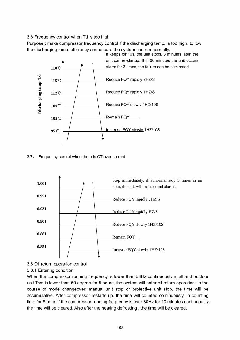
3.6 Frequency control when Td is too high Purpose : make compressor frequency control if the discharging temp. is too high, to low the discharging temp. efficiency and ensure the system can run normally.
3.7、 Frequency control when there is CT over current
3.8 Oil return operation control 3.8.1 Entering condition When the compressor running frequency is lower than 58Hz continuously in all and outdoor unit Tcm is lower than 50 degree for 5 hours, the system will enter oil return operation. In the course of mode changeover, manual unit stop or protective unit stop, the time will be accumulative. After compressor restarts up, the time will counted continuously. In counting time for 5 hour, if the compressor running frequency is over 80Hz for 10 minutes continuously, the time will be cleared. Also after the heating defrosting , the time will be cleared.
If keeps for 10s, the unit stops. 3 minutes later, the unit can re-startup. If in 60 minutes the unit occurs alarm for 3 times, the failure can be eliminated
Reduce FQY rapidly 2HZ/S
Reduce FQY rapidly 1HZ/S
Reduce FQY slowly 1HZ/10S
Remain FQY
Increase FQY slowly 1HZ/10S
Dis
char
ging
tem
p. T
d
118
115
112
109
105
95
1.00I
0.95I
0.93I
0.90I
0.88I
0.85I
Stop immediately, if abnormal stop 3 times in an hour, the unit will be stop and alarm .
Reduce FQY rapidly 2HZ/S
Reduce FQY rapidly HZ/S
Reduce FQY slowly 1HZ/10S
Remain FQY
Increase FQY slowly 1HZ/10S
108

3.8.2 Procedure Cooling mode: refer to “the oil return procedure in cooling mode”
Heating mode: refer to “the oil return procedure in heating mode” 3.8.3 The protection treatment in oil return operation: In the course of cooling oil return, because of all kinds of protection or abnormal unit stop, after the unit restart, the time will not be cleared, the system need another oil return operation. In the refrigerant flow course in oil return of cooling mode or after oil return, and within 5 minutes after the refrigerant being eliminated is over, the anti-freeze protection and low pressure protection are invalid, other protection is valid. In the course of heating oil return ,because of all kinds of protection or abnormal unit stop, the system need not another oil return operation after the unit stop for 3 minutes and enter in heating mode directly. In the course of changing to cooling oil return, the anti-freeze protection and low pressure protection are invalid, other protection is valid. Oil return procedure in cooling mode:
Quit condition of oil return: 1 minute later after oil return is over
& Td‐Tcm>30 OR OR Ts‐Tc>30
Tc<‐35 Max. 10 minutes
Oil return procedure in heating mode:
Send oil return signal oil return beginning oil return over
60 秒 ref.eliminated 30s 80 Hz(E)
40HZ(E) Inverter compressor auto FQY
300pulse(E) outdoor unit PMV auto open angle auto open angle
120pulse(E)
Outdoor fan motor auto operation auto(TC or ambient control) auto operation
running indoor motor auto operation auto(set fan speed) auto operation
stop indoor motor stop stop stop
4-way valve OFF OFF OFF
109

Quit condition of oil return Max. 9 minutes(E)
OR OR Td‐Tcm<20 for 30s(5 minutes later, begin to count) & Ts‐Tc<15 for 30 秒(5 minutes later, begin to count)
Running for min. 5 minutes(E)
Send oil return signal oil return beginning oil return over
Inverter compressor indicated FQY 60s oil return frequency 120s Soft startup
0HZ 0HZ 5s
outdoor motor auto auto auto(TC control)
4-way valve ON
OFF 15s 450pulse 450 pulse
300pulse(E) PMV auto open angel auto open angle
all indoor motor ON OFF anti-freeze startup
110

5.2 Indoor unit5.2.1 PCB(0151800106) for 28/36/48/60 indoor unit
111
YHDJXH018BAM--GX

A
TO OUT DOOR
0150507096
SW1-1
SW1-7
SW1-8
TYPE DEFINE
OFF
OFF
Cassette
OFF
ON
Convertible(≤24000BTU)
ON
OFF
Duct
ON
ON
Convertible(>24000BTU)
SW1-2 SW1-3 BTU
B:BLACK
R:RED
W:WHITE
Y/G:YELLOW/GREEN
TEM
P.
SENS
OR
ROOM
SENS
OR
PIPI
NG T
EMP.
RE
MO
TE
REC
EIVE
R
FLO
AT
SWIT
CH
CN5
TR
HEATER
PUMP
SWING
FAN
LEFT/
RIGHT
UP/
DOWN
CN9
CN8
CN7
CN11
PANNEL
REMOTE
CENTRAL CN3
CN1
CN29
CN20 CN18 CN21 CN13 CN12
ON
CN14
CN15
CN10
CN19
T3.15A/250VAC
FUSE
87654321
4321
ON
S
W1
SW
2
Wired
Remote
Controller
RC
2 1
3 B
W
R
Y/G
OFF
OFF
OFF
ON
OFF
OFF
OFF
ON
OFF
ON
ON
OFF
OFF
OFF
ON
ON
OFF
ON
OFF
ON
ON
ON
ON
ON
7000
9000
12000
14000
18000
24000
28000
36000
NOTE1.DASHED PART ARE OPTIONAL.
2. USER SHOULD NOT TO SET SW1 AND SW2.
CH3
CH4
CH5
OFF
OFF
OFF
OFF
SW1-4
SW1-5
SW1-6
OFF
OFF
OFF
OFF
ON
ON
OFF
ON
5.2.2. YHKJXH012/18/24BAM--FX YHFJXH012/18/24BAM--FX YHEJXH024BAR--GX
112

YHEJXH028/36/48BAR--GX
12
3
3H
C
4H
C
5H
C
LN
MM
OC
11N
C
M
NL
HM
3LR
2LR
1LR
91N
C01
NC
51N
C41
NC
7N
C9
NC
8N
C
ETO
MER
LA
RTNE
C
LEN
NAP
NAF
MM
MM
PU
NW
OD
TFELT
HGI
RG
NIWS
TAE
H
PM
UP
ES
UF
V052/A51.3T
DERI
WET
OME
RRELL
ORT
NO
CET
OME
RREVIE
CIER
MO
OR
DR
AC
HCTI
WS TA
OLF
MO
OR
.PMET
ROS
NES
GNIPIP
.PMET
ROS
NES
3N
C02
NC
92N
C2
NC
81N
C12
NC
31N
C21
NC
TIN
U R
OO
DTU
O OT
lanoitpo era trap dehsaD.1:eto
N2
ws dna 1ws tes ton dluohs res
U.2
WR
BG/
Y
WW
B
B
2-1W
S1-1
WS
3-1W
SUT
BN
OFF
ON
ON
ON
OO
NO
NO
FFO
NO
NO
FFO
00082000630008400006
7-1W
SFF
OFF
ON
ON
OFF
ON
ON
OFF
O
epyTettessa
Celbitrevno
Ctcu
Dgnidnats roolF
8-1W
S4-1
WS
5-1W
S
6-1W
S
NO
FFO
NO
FFO
NO
FFO
elbaliava drac moo
Relbaliavanu drac
mooR
ylno looC
pmup tae
Hetasnep
moc erutarepmet hti
Wetasnep
moc erutarepmet tuohti
W
D
ER:
R
KC
ALB:
B
ETIH
W:W
NE
ER
G/W
OLLEY:
G/Y
RT
5N
C
2W
S
1W
S
8379050510
N
R
113

A
TEM
P.
SENS
OR
ROOM
SENS
OR
PIPI
NG T
EMP.
REM
OTE
RE
CEIV
ER
FLOA
T SW
ITCH
ON ON
SW1
SW2
21
3
SW
1-1
SW
1-2
SW
1-3
BTU
OFF
ON
ON
2800
0
ON
ON
ON
3600
0
ON
ON
OFF
4800
0O
NO
NO
FF60
000
Floo
r sta
ndin
g
SW
1-7
SW
1-8
Type
def
ine
Cas
sette
Con
verti
ble
Duc
t
OFF
OFF
ON
ON
ON
OFF
OFF
ON
SW
1-4
OFF
ON ON
SW
1-5
OFF
SW
1-6
ON
OFF
room
car
d un
avai
labl
e
cool
onl
yhe
at p
ump
room
car
d av
aila
ble
With
tem
pera
ture
com
pens
ate
No
tem
pera
ture
com
pens
ate
YHKJXH028/36/48/60BAR--FX YHFJXH028/36/48BAR--FX YHGJXH048/60BAR--GX
114

TEMP.
SENSOR
ROOM
SENSOR PIPING TEMP.
DC
FAN
MO
TOR
SW1
SW2
REMOTE RECEIVER
FLOAT SW
ITCH
ALARM OR AIR EXCHAGELINKAGE
21
3
M
YHDJXH012/18/24BAM--GX
115

5.2.5.. Electrical Control Functions For Cassette and Convertible type 1. Dip switch functions:
A
YHKJXH*BAM--FX,YHFJXH*BAM--FX,YHDJXH024-060BAR--GX
wiring controller address SW2-1 SW2-2 SW2-3 SW2-4
0 0 0 0slave unit 1
slave unit 2
slave unit 3
………… ………… ………… ………… …………
slave unit 15 ON ON ON ON
SW2: wiring controller communication address
when the wiring controller is used to control many units , the wiring controller communicationaddress of indoor unit need be setted
SW1-1 SW1-2 SW1-3 SW1-4 SW1-5 SW1-6 SW1-7 SW1-8 Description1 0 --- --- --- --- --- 24K indoor
10 --- --- --- --- --- 28K indoor1 1 --- --- --- --- --- 36K indoor
11 --- --- --- --- --- 48K indoor1 1 --- --- --- --- --- 60K indoor--- --- --- 0 --- --- --- --- Room card invalid--- --- --- 1 --- --- --- --- Room card valid(default)--- --- --- --- 0 --- --- --- Cooling only--- --- --- --- 1 --- --- --- Heat pump (default)--- --- --- --- --- 0 --- --- Without tempetature compensation--- --- --- --- --- 1 --- --- With tempetature compensation--- --- --- --- --- --- 1 0 Duct--- --- --- --- --- --- 00 Cassette--- --- --- --- --- --- 0 1 Capinet ≥48K(or convertible ≤24K)
--- --- --- --- --- --- 11 Capinet(or convertible ≥28K)
------------
---
slave unit 4
0 0 0 0
0 0 0 0
0 0 0 0
116
YHDJXH*BAM--GX dip switch setting
SW1-1 SW1-2 SW1-3 SW1-4 SW1-5 SW1-6 SW1-7 SW1-8 Description011 ――――― 09K indoorunit100 ――――― 12K indoorunit
00 0 ―――― ― 18K indoorunit011 ―――― ― 24K indoorunit――― 00 ―― ― Static pressure Opa――― 0 1 ――― Static pressure10pa
―― ― 1 0 ―― ― Static pressure 20pa―― ― 1 1 ―― ― Static pressure 30pa―――― ― 1 ― ― Room card valid―――― ― 0 ―― Room card invalid――――― ― 0 0 Slim duct(AD**SS1ERA)
1:ON 0:OFF

2. Sign definition:Indoor outdoor
Tai Tc1 Tc2 Tm Tao Toci Tc Te Ts Td
Ambient
temp.
Outlet
pipe
temp.
Inlet
pipe
temp.
mid
coil
temp.
Ambient
temp.
Thick pipe
of heat
exchanger
mid
condenser
temp.
Defrost
temp.
Compressor
suction
temp.
Compressor
discharging
temp.
Tcomp1,2 Tset
Temp. compensation Set
temp.
3. Dry operationTai<16, indoor unit stops running and sends stop-unit signal to outdoor. Tai≤Tset, indoor motor runs at low speed and sends stop-unit signal to outdoor. 4. Fan operationIndoor fan motor will run as the fan speed set on the remote controller or the wired controller and indoor unit will send the stop-unit signal to outdoor. 5. Auto operation5.1 If the unit enters Auto mode for the first time, the system will adjust the operation mode according to the room temp. and the set temp. When Tai≥Tset, entering auto cooling mode; When Tai<Tset, entering auto heating mode. 5.2 Auto cooling mode is as the same as the cooling mode. After the thermostat is OFF for 15 minutes, if Tai+ 1+Tcomp2<Tset, the unit will enter auto heating mode, or the unit will still stay at auto cooling mode and stop when it reaches the set temperature; while the indoor motor will be at low speed. 5.3 Auto heating mode is as the same as the heating mode. After the thermostat is OFF for 15 minutes, if Tai≥Tset+1 +Tcomp1, the unit will enter auto cooling mode, or the unit will still stay at auto heating mode; 5.4 In this mode, the Sleep function is available, run as cooling sleep in cooling mode and as heating sleep in heating mode. Once sleep mode is set, the mode will not change after the unit stops for 15 minutes when it arrives Tset. 5.5 Mode conversion will be confirmed after compressor has stopped for 10 minutes. 6. Abnormal operation6.1 When outdoor modes from the request of indoor unit conflict, the one entering firstly will take priority.
ERA
6.2 After indoor receives the ON command from wired controller, it will firstly confirm the outdoor current operation mode. If they are the same modes, indoor unit will run as the request of remote controller. If they are different modes, the system will forbid to operate, and indoor will keep the OFF mode and send the “standby” signal to wired controller until outdoor stops or outdoor mode the requested mode of wired controller are the same, the unit will run as the requested mode of wired controller. 6.3 After indoor receives the ON command from remote controller, it will firstly confirm the outdoor current operation mode. If they are the same mode, indoor unit will run as the request of remote controller. If they are different modes, the system will forbid to operate, and indoor will keep the OFF mode. After setting on remote controller, if the buzzer sounds two times, that shows abnormal operation. Indoor will run until the outdoor mode and the requested mode of remote controller are the same.
117

6.4 In AUTO mode, when the indoor unit occurs abnormal operation, the indoor unit will keep OFF state, and the buzzer will not sound until the outdoor mode and the requested mode of indoor unit are the same. 6.5 COOL (included AUTO COOL), DRY, FAN are not abnormal mode. 6.6 HEAT and FAN are not abnormal mode. 7. Control for discontinuous operationAfter the unit starts up in cooling/heating mode, in 5 minutes, the compressor run/stop will not be controlled by the room temp., but after changing the set temp., if compressor stop condition can be met, the system will stop compressor immediately. 8. Anti-cold air controlIn heating mode, after compressor startup, the system will control indoor fan motor according to indoor coil temperature. Detailed operation is as below:
Tc2() 30(32) set speed
26(30) low speed
22(26) off
20(20)
Note: 1) The data in the parentheses is the control point when Tao>10;2) Indoor unit will send “pre-heat” signal to wired controller in anti-cold air period.9. Fan motor control in defrosting9.1 On receiving outdoor defrosting signal, indoor unit will stop after blowing remaining heat at slow speed for 20 seconds. 9.2 In defrosting period, indoor fan motor stops running. 9.3 Defrosting is over, and indoor motor will run as anti-cold air state. 10. Blowing remaining heat operationWhen the unit shuts off in heating mode or the thermostat is OFF, indoor motor will stop running after running at low speed for 30 seconds. 11. Swing motor controlIndoor unit will control the swing motor according to the swing signal from the wired controller.
Full OFF 54º
0°
Standard position in HEAT, COOL mode
Swing range54°
118

12. Water pump control12.1 Water pump will be electrified when indoor unit enters non-heating mode until indoor unit stops. 5 minutes later after indoor unit stops, water pump will stop. 12.2 When indoor unit is in heating mode, water pump will not operate. 12.3 In OFF state and in any mode, once float switch signal is measured, indoor unit will send OFF signal to outdoor and send the failure code of drainage system to the wired controller, then the water pump will work until the float switch signal is cancelled. After water pump is forced to run for 5 minutes, indoor unit will be back to normal state. 13. Compulsory defrosting operation13.1 After indoor receives the compulsory defrosting signal, it will send continously the signal to outdoor for 10 times, in this period, indoor unit will work normally and it will enter defrosting operation until it receives the enter-defrost signal from outdoor unit. 13.2 Wired control type: In heating mode, make a jumper for D2 to enter compulsory defrosting. 13.3 Remote control type: In heating mode, high speed, 30, press SLEEP button 6 times, and the buzzer will sound 3 times, then enter the manual defrosting. 14. Trial operation14.1 Enter condition A. Wired control type: In OFF state of COOL or HEAT mode, press ON/OFF button for over 5 seconds to
enter the cooling or heating trial operation; B. Remote control type: In OFF state, keep pressing ON/OFF button until 5 seconds later, the buzzer
sounds twice, then enter the cooling or heating trial operation; 14.2 Response in trial operation A. Cooling trial operation: indoor sends S-CODE=SD to outdoor, indoor: at high speed, set temp: 16; B. Heating trial operation: indoor sends S-CODE=SF to outdoor, indoor: at high speed, set temp: 30; C. In this period, anti-freezed and overheat functions are invalid. 14.3 Quit condition A. Receiving the signal of cancelling trial operation from wired controller or remote controller; B. After trial operation has run for 20 minutes, it will quit trial operation automatically and enter the
normal mode with the set temp.: 24. 15. Timer operation15.1 Wired control type: wired controller will control the unit ON/OFF; 15.2 Remote control type: indoor unit will confirm the unit ON or OFF according to the current clock and the timer clock set by remote controller. When setting timer function, the timer LED will be ON. 16. SLEEP function16.1 Wired control type unit is without sleep function; 16.2 Remote control type unit consists of cooling sleep and heating sleep, after the sleep is set, the unit
A
will change mode; the sleep will begin to count. A. In cooling/dry mode, after running for 1 hour, the set temp. will increase 1, another 1 hour later, the
set temp. will increase 1 again, then 6 hours (or set time-2) later , it will stop. B. In heating mode, after running for 1 hour, the set temp. will reduce 2, another 1 hour later, the set
temp. will reduce 2 again, then 3 hours later, the set temp. will increase 1, and another 3 hours(or set time-5), it will stop.
C. When setting sleep function, indoor motor is forced at low speed.
119

17. Healthy negative ion functionWhen receiving the healthy signal from the wired controller or remote controller, if fan motor is running, the negative ion will work; If the fan motor stops, the negative ion generator will stop. 18. Auto-restart function18.1 Wired control type: jumper J07 at high level, auto-restart is available, if at low level, auto-restart is cancelled; when out of factory, the unit is with auto-restart function. 18.2 Remote control type: In 5 seconds, press SLEEP button(press SWING if without SLEEP button) 10 times continuously, the buzzer will sound 4 times and enter auto-restart function. In 5 seconds, press SLEEP 10 times continuously, the buzzer will sound twice and quit auto-restart function. 18.3 Memory information: ON/OFF state, mode, fan speed, set temp., health, swing position; 18.4 If the memory includes timer or sleep function, when being electrified again, timer and sleep will be cancelled; 18.5 If the memory includes auto mode, when the jumper shows cooling only type, auto mode will change to cooling mode.
A
19. Room card functionThe unit adopts room card function(220VAC input), which only make ON/OFF control. When it is connected, the unit is ON; when it is disconnected, the unit is OFF, and the other parameters will be as default or the data in memory. 19.1 When room card function is available The central control, remote control/wired control and the room card are “AND” logical relationship. On the condition that the room card is connected, the unit can be controlled by remote controller or wired controller; indoor unit will run at the set state by the central controller, remote controller or wired controller; otherwise, if room card is not connected, the unit can not be controlled. 19.2 When room card function is not available The unit will be controlled by the remote controller, the wired controller or the central controller.
120

A. Wired control type unit: this function is not available B. Remote control type unit: In cooling or heating mode, there is always with the temp. compensation. In heating mode: In 24 heating mode, press SLEEP(or SWING) button 7 times continuously within 5 seconds, indoor buzzer sounds twice, that shows temp. compensation works. Switch on the unit in heating mode by the remote controller, press TEMP button to set the set temp., so temperature compensation=the current set temp. - 24. For example, if the set temp. is 24, the temp. compensation is 0; if the set temp. is 25, the temp. compensation is 1. The max. compensation temp. is 6 (the set temp. is 30). If you want to cancel it, set the temp. as 24.
In cooling mode: In 24 cooling mode, press SLEEP(or SWING) button 7 times continuously within 5 seconds, indoor buzzer sounds twice, that shows temp. compensation works. Switch on the unit in heating mode by the remote controller, press TEMP button to set the set temp., so temperature compensation=24-the current set temp. . For example, if the set temp. is 24, the temp. compensation is 0; if the set temp. is 23, the temp. compensation is -1. The max. compensation temp. is -8 (the set temp. is 16). If you want to cancel it, set the temp. as 24.
So the temp. compensation range is +8~-6.
When compressor has run for over 5 minutes, to prevent indoor evaporator freezing (in cooling/dry mode), if indoor mid-coil temp. is below -1 degree for over 5 minutes, indoor EEV will close, and compressor will stop. When indoor mid-coil temp. is over about 10 degree, the unit will be normal.
seconds, indoor will stop; while when indoor mid-coil temp. is below 52 degree for 3 seconds, indoor will resume.
20. Setting method of temperature compensation Tcomp
21. Anti-freezed protection
It is valid only in heating mode, if indoor mid-coil temp. is over about 65 degree continuously for 10 22. Overload protection in heating mode
121

6. Diagnostic code and trouble shooting6.1.1. Diagnostic code for outdoor unit
Flash times ofLED on
mainboardTrouble description Analyze and diagnose
1 Eeprom failure Outdoor main board eeprom fail
2 IPM failure IPM failure
4Communication error between main board and spdu module SPDU Communicition error
Communication fail over 4 min
5 High pressure protection System high pressure over 4.15 Mpa
6
Module over-voltage protection(only for Spdu)Module lack-voltage protection(only for Spdu)
Send from Spdu module
8 Compressor discharging temperature protection
Compressor discharging temperature over 110 centigrade
9 Abnomal of DC motor jam of DC motor or motor failure
10 Abnomal of pipe sensor Piping sensor short-circuit or open-circuit
12 Abnomal of outdoor ambient sensor Outdoor ambient sensor short-circuit or open-circuit
13 Abnormal of compressor dischage sensor
Compressor discharging sensor short-circuit or open-circuit
15 Communication error between indoor and outdoor unit Communication fail over 4 min
16 Lack of refrigerant check if there is leakage in the unit
17 4-way valve reverse failure
Alarm and stop if detect Td-Tci<=15 last for 1min after compressor has started for 10min in heating mode, confirm the failure if it appears 3 times in one hour.
18 Compressor jam (ony for spdu ) Inner compressor is abnormal jamed
19 Module EEV select circuit error Module EEV select wrong circuit
25 Compressor U-phase over-current The current of compressor U-phase is too high
25 Compressor V-phase over-current The current of compressor V-phase is too high
25 Compressor W-phase over-current The current of compressor W-phase is too high
45 Low pressure protection System over pressure under 0.05Mpa
YHUJYH024BAR-A-X
122

PRODUCT DIAGNOSIS PROCEDURE
EEPROM faulty
If it occurs 3 times in 1 hour, confirm the failure, the former twice will not alarm
Over current protection in course of compressor frequency going down detected by software
Non-resumable
Non-resumableresumable
Module abnormal, if it occurs 3 times in 1 hour, confirm the failureprotection of over current in course of compressor fixed speed operation
If it occurs 3 times in 1 hour, confirm the failure, the former twice will not alarm
Module temp. too high or module temp.sensor abnormal
Non-resumable
Non-resumable
Communication abnormal between connecting board and module
It can not get the feedback from module after communicating for 4 minutes resumable
Compressor overcurrentIf it occurs 3 times in 1 hour, confirm the failure, the former twice will not alarm Non-resumable
Compressor blocked or abnormal operation
If it occurs 3 times in 1 hour, confirm the failure, the former twice will not alarm Non-resumable
After compressor starts up, if TD is over 115 , 10 seconds later compressor stops, if it occurs 3 times in 1 hour, confirm the failure
Protection of discharging temp. too high Non-resumable
DC fan motor faulty If it occurs 3 times in 1 hour, confirm the failure, the former twice will not alarm Non-resumable
Sensor is detected below 20 or over 1000 for 60 seconds, but incooling mode,this sensor failure will not be dealt with,and in defrosting or within 6 minutes after defrosting,it will not alarm.
Outdoor defrosting temp. sensor abnormal resumable
Suction temp.sensor abnormal If it occurs 3 times in 1 hour, confirm the failure, the former twice will not alarm
resumable
Ambient temp. sensor abnormal Sensor is detected below 20 or over 1000 for 60 seconds, but in frosting or within 6 minutes after defrosting, it will not alarm resumable
Discharging temp. sensor abnormal After compressor running for 3 minutes, Sensor is detected below 20 or over 1000 for 60 seconds
resumable
Indoor unit can not be inspected for 4 minutes continuously resumablecommunication between indoor and outdoor abnormalLack of refrigerant or discharging pipe blocked
If it occurs 3 times in 1 hour, confirm the failure. Non-resumable
4-way vavle converse abnormal If it occurs 3 times in 1 hour, confirm the failure. Non-resumable
Over current in course of compr-essor frequency going down
If it occurs 3 times in 1 hour, confirm the failure, the former twice will not alarm
Non-resumable
If it occurs 3 times in 1 hour, confirm the failure, the former twice will not alarm
Over current protection in course of compressor fixed speed opera-tion detected by software Non-resumable
If it occurs 3 times in 1 hour, confirm the failure, the former twice will not alarm
Over current protection in course of compressor frequency going up
down detected by software Non-resumable
Non-resumableIf it occurs 3 times in 1 hour, confirm the failure, the former twice will not alarmWithout connection to compressor
High voltage protection for module
From moudle board resumable
resumableFrom module boardLow voltage protection for module
Communication abnormal among modules
It can not detect the input signal for 2 minutes Non-resumable
resumableSensor is detected below 20 or over 1000 for 60 seconds, but in defrosting or within 6 minutes after defrosting, it will not alarm
Mid-condenser temp. sensor abnormal
After compressor running for 3 minutes, if switch is detected unconnected for 30seconds, it alarms, if it occurs 3 times in 1 hour, confirm this failure, if it occurs 3 times in 1 hour, confirm the failure, but in defrosting or within 6 minutes after defrosting, it will not alarm
Low pressure switch abnormal
High pressure switch abnormalAfter compressor running for 3 minutes, if switch is detected uncon-nected for 30seconds, it alarms, if it occurs 3 times in 1 hour, confirm this failure, or if Tcm is over 68 degree for 10 seconds for 3 times
Non-resumable
Note: The flash times of outdoor mainboard(ECU) LED1 indicates the malfuction code. for example, LED1 flash 3 times, the malfuction code is 3.The flash times or malfuction code of indoor unit can also indictes the malfuction code too.the method to confirm please refer to indoor unit manul.
Non-resumable
Malfunction Code Trouble Description Analyze and diagnose Remark
YHUJYH024BAR-A-X YHUJYH028BAR-A-X YHUJYH036BAR-A-X YHUJYH048BAR-A-XYHUJYH048BAS-A-X YHUJYH060BAS-A-X
123

6.1.2. Diagnostic code for indoor unit
Flash times ofTiming LED(orindoor PCBLED4)
Flash times ofRunning LED(orindoor PCBLED3)
Failure code(fromwired controller)
Failurecode(from panelcontroller )
trouble shooting Possible reasons
10 01 E1 Temperature sensorTa faulty
Sensor disconected,or broken,orat wrong position,or short circuit
0 2 02 E2 Temperature sensorTe faulty
Sensor disconected,or broken,orat wrong position,or short circuit
0 4 04 F8 EEPROM WRONG Faulty indoor unit PCB
0 7 07 E9
Abnormalcommunicationbetween indoor andoutdoor units
Wrong connection,or the wires bedisconected,or wrong addresssetting of indoor unit,or faulty powersupply or faulty PCB
80NO EEROR
CODE DISPLAY E8
Abnormalcommunicationbetween indoor wiredcontroller and indoor
Abnormal communication betweenindoor wired controller and indoor unitPCB
0 12 0C E0
unit PCB
Drainage systemabnormal
Pump motor disconnected,or atwrong position,or the float switchbroken down,or the float switchdisconected,or at wrong position.
0 13 OD EF Zero cross sigal wrong Zero cross sigal detected wrong
0 14 0E / Indoor unit DC fanmotor abnormal
DC fan motor disconnected,or DC fanmotor broken,or circuitbroken
0 16 10 F3 Indoor mode abnormal Different from outdoor unit mode2 1 15 / Outdoor unit abnormal2 2 16 / Outdoor unit abnormal2 4 18 / Outdoor unit abnormal2 5 19 / Outdoor unit abnormal2 7 1B / Outdoor unit abnormal2 8 1C / Outdoor unit abnormal2 9 1D / Outdoor unit abnormal3 0 1E / Outdoor unit abnormal3 1 1F / Outdoor unit abnormal3 2 20 / Outdoor unit abnormal3 3 21 / Outdoor unit abnormal3 5 23 / Outdoor unit abnormal3 6 24 / Outdoor unit abnormal3 7 25 / Outdoor unit abnormal3 8 26 / Outdoor unit abnormal3 9 27 / Outdoor unit abnormal4 3 2B / Outdoor unit abnormal4 4 2C / Outdoor unit abnormal4 7 2F / Outdoor unit abnormal4 8 30 / Outdoor unit abnormal4 9 31 / Outdoor unit abnormal5 8 3A / Outdoor unit abnormal5 9 3B / Outdoor unit abnormal6 3 3F / Outdoor unit abnormal6 4 40 / Outdoor unit abnormal
1.. For the indoor failu ,only running LED ON remote receiver will indicate.2.. For the outdoor failu ,timer LED and running LED will indicate.timer LED of remote receiver stands for ten's place,and running LEDstands for one's place.timer LED will flash firstly,2 seconds later,running LED will flash too. Afer that,4 seconds later,they will flash inturns again.Flash times equals to the failure code of outdoor plus20.For example,failure code of outdoor is 2,the indoor unit should display 22.As a result,timer LED flashes twice firstly,then running LEDflashes twice.
To get much more details of outdoor unit failure,Please refer to the the outdoor unit trouble shooting list3.
Refer to the outdoor unit troubleshooting
list
124

6.2. Trouble Shooting: Trouble 1: No display on the operation panel
start
nocheck if display panel and the unit matched well
no no
yes
replace display panel and check again
if the red diode and green diode on indoor PCB flash in turn
yes yes
if the power terminal block is 220V input
check the terminal block and the power supply
PCB is faulty, replace it
check if display panel is 12V power supply
no no nocheck if power wiring is in open circuit
yes yes yes
check if fuse is burnt
PCB is faulty, replace
display panel circuit is damaged, replace it
replace power wiring and check again
replace the fuse and check again
Trouble 2: Sensor failure
start
noas per the wiring diagram,check the connection between sensor and PCB is correct
re-fix the sensor and check again
check if sensor is in open circuit or PCB port is not in good condition
yes
yes yes
no nocheck if sensor resistor value is correct
replace sensor and check again
replace sensor and check again
PCB is faulty and repalce it, check again
125

no
start
as per the wiring diagram, check if communication wiring is correct
yes
yes yes
no no
re-wiring, and check again
check if the communication port connecting to the indoor/outdoor PCB is in open circuit
if the power cable and the communication wire are too close, resulting in the wrong commission data
PCB is faulty, replace and check again
replace the communication connection wire, check again
adjust the distance and check again
Trouble 4: Indoor PCB EEPROM data is wrong
1.If the failure occurs when being electrified for the first time, that shows EEPROM (8-bit pin) not fixed firmly or
damaged.
2.If the failure occurs when running, that shows EEPROM is faulty and need to be replaced.
Trouble 5: Indoor repeated unit number
Check the failure code on outdoor indicator board (5-lamp)
Trouble 3: Communication failure between indoor and outdoor
Trouble 5: Outdoor unit failure
start
no
yes
no no
yes
as per the wiring diagram, check if connection port between sensor and PCB is correct
re-fix the sensor and check again
check if the sensor is in open circuit or the connection port to PCB is in good condition
check if the sensor resistor value is correct
replace sensor and check again
replace sensor and check again
PCB is faulty and repalce it, check again
yes
Trouble 6: Outdoor unit alarms sensor failure
126

rotor, compressor great vibration, compressor abnormal startup, state detecting curcuit abnormal or
compressor damaged.
The former twice failure can be resumed automatically, if outdoor board occurs this failure always, and
can not be resumed for a long time, that shows:
1. Power module (SPDU) damaged, please replace the power module, then re-wiring as per the wiring
diagram (70% possibility)
2. Short circuit in power board results in the power module damaged (15% possibility)
3. Damaged compressor results in this failure (10% possibility)
4. Main control board is faulty, replace it (5% possibility)
Trouble 10: High pressure failure
Reasons:
1. Over high system pressure results that the unit stop, and the compressor protection will work. The
failure can be resumed.
2. Pressure switch wire is not fixed well or in open circuit.
start
nocheck if the connector between pressure switch and PCB is fixed badly or damaged
no no
no
yes yes yes
check if the 2 straight lugs on the pressure switch are in good condition
if outdoor fan motor cannot startup normally in cooling mode
replace main control board and check again
replace pressure switch connector, shut off and be electrified again, re-check
replace pressure switch connector, shut off and be electrified again, re-check
check if the outdoor motor has power input
replace outdoor motor and check again
Trouble 7: AC current over current protection or current transducer damaged, or compressor blocked
127

7. Outdoor performance curves
2.00
3.00
4.00
5.00
6.00
7.00
8.00
10/6 21/15 25/18 32/20 38/24 43/26 46/26 53/32Outdoor DB()
Capa
city(
KW)
18/1220/14.522/1625/1827/1930/2232/23
5.00
5.50
6.00
6.50
7.00
7.50
8.00
8.50
-7/-8 -5/-6 2/1.5 7/6 11/9 16/12 19/15 24/18Ourdoor DB()
Capa
city (
KW)
16/1018/1220/14.522/1624/1726/18
YHUJYH024BAR-A-X heating capacity curves
YHUJYH024BAR-A-X cooling capacity curves
128

Heating capacity curves
4000
5000
6000
7000
8000
9000
10000
11000
12000
16/10 18/12 20/14.5 21/15 22/16 24/17 26/18
indoor DB/WB
Hea
ting
capa
city
(W)
-6/-7-4/-5-1/-21/06/57/612/1016/15
Cooling capacity curves
3000
4000
5000
6000
7000
8000
9000
10000
18/12 20/14 22/16 25/18 27/19 30/22 32/24
indoor DB/WB
Coo
ling
capa
city
(W)
-52025323540
YHUJYH028BAR-A-X
129

0500
100015002000250030003500400045005000550060006500700075008000850090009500
10000105001100011500120001250013000
16/10 18/12 20/14.5 21/15 22/16 24/17 26/18indoor WB/DB
-6/-7 heatingcapacity-6/-7 powerinput-4/-5 heatingcapacity-4/-5 powerinput0/-1 heatingcapacity0/-1 power input
2/1 heatingcapacity2/1 power input
6/5 heatingcapacity6/5 power input
7/6 heatingcapacity7/6 power input
12/10 heatingcapacity12/10 powerinput16/15 heatingcapacity16/15 powerinput
43
0500
100015002000250030003500400045005000550060006500700075008000850090009500
10000105001100011500120001250013000
12/18 14/20 16/22 18/25 19/27 22/30 24/32
indoor WB/DB
cool
ing
capa
city
(W)/p
ower
inpu
t(W)
20 cooling capacity
20 power input
25 cooling capacity
25 power input
32 cooling capacity
32 power input
35 cooling capacity
35 power input
40 cooling capacity
40 power input
YHUJYH036BAR-A-X heating capacity curves
YHUJYH036BAR-A-X cooling capacity curves
YHUJYH036BAR-A-X
130

0
1000
2000
3000
4000
5000
6000
7000
8000
9000
10000
11000
12000
13000
14000
15000
16000
17000
18000 ‐6/‐7 heating capacity‐6/‐7 power input‐4/‐5 heating capacity‐4/‐5 power input‐1/‐2 heating capacity‐1/‐2 power input1/0 heating capacity1/0 power input
6/5 heating capacity6/5 power input
7/6 heating capacity7/6 power input
12/10 heating capacity12/10 power input27/18 heating capacity
0
1000
2000
3000
4000
5000
6000
7000
8000
9000
10000
11000
12000
13000
14000
15000
16000
18/12 20/14 22/16 25/18 27/19 30/22 32/23
20/15 cooling capacity
20/15 power input
25/18 cooling capacity
25/18 power input
32/23 cooling capacity
32/23 power input
35/24 cooling capacity
35/24 power input
40/26 cooling capacity
40/26 power input
16/10 18/12 20/14.5 21/15 22/16 24/17 26/18 27/18 power inputindoor WB/DB
YHUJYH048BAS-A-X heating capacity curves
cooling capacity curves
indoor WB/DB
YHUJYH048BAS-A-X
131

Ourdoor DB()
YHUJYH060BAS-A-X cooling capacity curves
Outdoor DB()
YHUJYH060BAS-A-X heating capacity curves
0
1000
2000
3000
4000
5000
6000
7000
8000
9000
10000
11000
12000
13000
14000
15000
16000
17000
18000
19000 ‐6/‐7 heating capacity‐6/‐7 power input‐4/‐5 heating capacity‐4/‐5 power input‐1/‐2 heating capacity‐1/‐2 power input1/0 heating capacity1/0 power input
6/5 heating capacity6/5 power input
7/6 heating capacity7/6 power input
12/10 heating capacity12/10 power input27/18 heating capacity
0
1000
2000
3000
4000
5000
6000
7000
8000
9000
10000
11000
12000
13000
14000
15000
16000
17000
18/12 20/14 22/16 25/18 27/19 30/22 32/23
20/15 cooling capacity
20/15 power input
25/18 cooling capacity
25/18 power input
32/23 cooling capacity
32/23 power input
35/24 cooling capacity
35/24 power input
40/26 cooling capacity
40/26 power input
16/10 18/12 20/14.5 21/15 22/16 24/17 26/18 27/18 power input
132

8.1 AB8. Indoor air velocity and temperature distribution curves
Cooling / Air Velocity DistributionCoolingBlowy angle:25Air Velocity Distribution
a.
CoolingBlowy angle:25Temperature Distribution
b. Cooling / Temperature Distribution
133

Air Velocity Distribution
CoolingBlowy angle:25
Temperature Distribution
CoolingBlowy angle:25
a. Cooling / Air Velocity Distribution
b. Cooling / Temperature Distribution
1.5m/s
1.0m/s
0.5m/s
8.2 For AC
134

9. Air flow and static pressure chart
1200130014001500160017001800190020002100220023002400
0 10 20 30 40 50 60 70 80 90 100
external static pressure
super high speedhigh speedmiddle speedlow speed
YHEJXH028/036BAR--GX external static pressure curves
100
90
80
70
60
50
40
30
20
10
00 200 20001200800400 600 1000 16001400 1800
3
2
1
1
3
2
External static pressure(Pa)
Air flow(m/h)3
high speedmid speedlow speed
YHDJXH024BAR--GX external static pressure curves
135
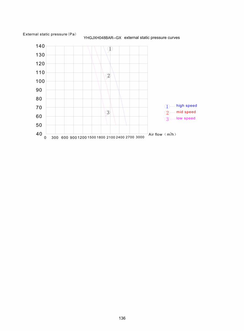
140
130
120
110
100
90
80
70
60
50
400 300 300018001200600 900 1500 24002100 2700
Air flow(m/h)3
3
2
1
low speed
mid speed
high speed1
3
2
External static pressure(Pa)YHGJXH048BAR--GX external static pressure curves
136

10. Noise level
;< $ / &&(!$
;< $ / 0
!+ ( / #$ , !& 0 )+ $ #$ $, !$0# 0 0#!,)$0+ $ &$3$& 3! $ 1, #$ !0(!& 1!0 (0# ! ,(0($- $0+
(3)
a. Casset type indoor unit
Test method According to the testing illustrator, the microphones wearing sponge style cover should be
placed in the right position
137

8111417202326293235384144475053
2531
.540
5063
8010
012
516
020
025
031
540
050
063
08
00
1000
1250
1600
2000
2500
3150
4000
5000
6300
8000
1000
012
500 16
0000
2000
0
Third
oct
ave
band
freq
uenc
y H
z
Sound pressure level DB
heat
ing
low
heat
ing
mid
dle
heat
ing
high
cool
ing
low
cool
ing
mid
dle
cool
ing
high
fan
low
fan
mid
dle
fan
high
2531
.540
5063
8010
012
516
020
025
031
540
050
063
08
00
1000
1250
1600
2000
2500
3150
4000
5000
6300
8000
1000
012
500 16
0000
2000
0
Third
oct
ave
band
freq
uenc
y H
z
heat
ing
low
heat
ing
mid
dle
heat
ing
high
cool
ing
low
cool
ing
mid
dle
cool
ing
high
fan
low
fan
mid
dle
fan
high
Noi
se le
vel-Y
HK
JXH
028B
AR
--FX
Noi
se le
vel-Y
HK
JXH
024B
AR
--FX
138

Noi
se le
vel-Y
HK
JXH
048B
AR
--FX
0102030405060
25
40
63
100
160
250
400
630
1000
1600
2500
4000
6300
1000
0
1600
0
third
oct
ave
band
freq
uenc
y H
z
sound pressure level DB
cool
ing
high
cool
ing
med
cool
ing
low
heat
ing
high
heat
ing
med
heat
ing
low
fan
high
fan
med
fan
low
101316192225283134374043464952
2531
.540
5063
8010
012
516
020
025
031
540
050
063
080
010
0012
5016
0020
0025
0031
5040
0050
0063
0080
0010
000
1250
0 1600
0020
000
Third
oct
ave
band
freq
uenc
y H
z
Sound pressure level DB
heat
ing
low
heat
ing
mid
dle
heat
ing
high
cool
ing
low
cool
ing
mid
dle
cool
ing
high
fan
low
fan
mid
dle
fan
high
Noi
se le
vel-Y
HK
JXH
036B
AR
--FX
139

Noi
se le
vel-Y
HK
JXH
060B
AR
--FX
81216202428323640444852566064
2531
.5
40
50
63
80
100
125
160
200
250
315
400
500
630
800
1000
1250
1600
2000
2500
3150
4000
5000
6300
8000
1000
0 1251
0060
000
2000
0
Third
oct
ave
band
freq
uenc
y H
z
Sound pressure level DB
heat
ing
low
heat
ing
mid
dle
heat
ing
high
cool
ing
low
cool
ing
mid
dle
cool
ing
high
fan
low
fan
mid
dle
fan
high
140

b. Convertible type indoor unit
(3) Test method According to the testing illustrator, the microphones wearing sponge style cover should be
placed in the right position
141

10
15
20
25
30
35
40
45
50
2531
.540
5063
8010
012
516
020
025
031
540
050
063
080
010
0012
5016
0020
0025
0031
5040
0050
0063
0080
0010
000
1250
10
6000
020
000
Third o
ctave
band fre
quency
Hz
Sound pressure level DB
heatin
g lo
wheatin
g m
iddle
heatin
g h
igh
coolin
g lo
wco
olin
g m
iddle
coolin
g h
igh
fan lo
wfa
n m
iddle
fan h
igh
Nois
e le
vel-
YH
FJX
H028/0
36B
AR
--F
X
1/3
oct
ave
band n
ois
e le
vel-
YH
FJX
H024B
AR
--F
X
8.0
13
.0
18
.0
23
.0
28
.0
33
.0
38
.0
43
.0
48
.0
53
.0
25.0
31.5
40.0
50.0
63.0
80.0
100.
012
5.0
160.
020
0.0
250.
031
5.0
400.
050
0.0
630.
080
0.0
1000
.0
1250
.0
1600
.0
2000
.0
2500
.0
3150
.0
4000
.0
5000
.0
6300
.0
8001
0.0
0000
1.0
2500
1.0
6000
2.0
0000
.0
third o
cta
ve b
and fre
quency H
z
Sound pressure level DB
coolin
g h
igh
coolin
g m
ed
coolin
g low
fan h
igh
fan m
ed
fan low
heating h
igh
heating m
ed
heating low
142

-64
Noi
se le
vel-Y
HFJ
XH
060B
AR
--FX
10152025303540455055
2531
.5
40
50
63
8010
0
125
160
200
250
315
400
500
630
800
1000
1250
1600
2000
2500
3150
4000
5000
6300
8000
1000
0 1215
0060
000
2000
0
Third
oct
ave
band
freq
uenc
y H
z
Sound pressure level DB
heat
ing
low
heat
ing
mid
dle
heat
ing
high
cool
ing
low
cool
ing
mid
dle
cool
ing
high
fan
low
fan
mid
dle
fan
high
Nois
e level-
YH
FJX
H048B
AR
--F
X
0
10
20
30
40
50
60
2540
6310
016
025
040
063
010
0016
0025
0040
0063
0010
000
1600
0
third o
cta
ve b
and fre
quency H
z
sound pressure level DB
cooling h
igh
cooling m
ed
cooling low
heating h
igh
heating m
ed
heating low
fa
n h
igh fan
med fan low
143

(3)
c. Duct type indoor unit
Test method According to the testing illustrator, the microphones wearing sponge style cover should be
placed in the right position
144
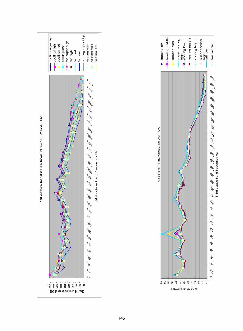
15
19
23
27
31
35
39
43
47
51
55
59
63
2531
.5
40
50
63
80
100
125
160
200
250
315
400
500
630
800
1000
1250
1600
2000
2500
3150
4000
5000
6300
8000
1000
012
500 16
0000
2000
0
Th
ird
oct
ave
ba
nd
fre
qu
en
cy H
z
Sound pressure level DB
he
atin
g lo
w
he
atin
g m
idd
le
he
atin
g h
igh
sup
er
he
atin
gh
igh
coo
ling
low
coo
ling
mid
dle
coo
ling
hig
h
sup
er
coo
ling
hig
hfa
n lo
w
fan
mid
dle
8.0
13
.01
8.0
23
.02
8.0
33
.03
8.0
43
.04
8.0
53
.0
25.0
31.5
40.0
50.0
63.0
80.0
100.0
125.0
160.0
200.0
250.0
315.0
400.0
500.0
630.0
800.0
1000
.012
50.0
1600
.020
00.0
2500
.031
50.0
4000
.050
00.0
6300
.080
00.0 10
000.0
1250
0.016
000.0
2000
0.0
third
oct
ave
ba
nd
fre
qu
en
cy H
z
Sound pressure level DB
coolin
g s
uper
hig
hco
olin
g h
igh
coolin
g m
ed
coolin
g lo
wfa
n s
uper
hig
hfa
n h
igh
fan m
ed
fan lo
wheatin
g s
uper
hig
hheatin
g h
igh
heatin
g m
ed
heatin
g lo
w
1/3
oct
ave
ban
d n
ois
e le
vel-
YH
DJX
H024B
AR
--G
X
No
ise
leve
l--Y
HE
JXH
02
8/0
36
BA
R--
GX
145

Nois
e le
vel-
YH
GJX
H048B
AR
--G
X
01 02 03 04 05 06 0
25
40
63
100
160
250
400
630
1000
1600
2500
4000
6300
1000
016
000
third o
ctave
band fre
quency
Hz
sound pressure level DB
coo
ling
hig
h
coo
ling
me
d
coo
ling
low
h
ea
ting
hig
h
he
atin
g m
ed
h
ea
ting
low
fa
n h
igh
fa
n m
ed
fa
n lo
w
29
third
oct
ave
band
freq
uenc
y H
z
1/3
octa
ve b
and
nois
e le
vel-Y
HG
JXH
060B
AR
--G
X
8.0
13.0
18.0
23.0
28.0
33.0
38.0
43.0
48.0
53.0
58.0
25.0
31.5
40.0
50.0
63.0
80.0
100.0
125.0
160.0
200.0
250.0
315.0
400.0
500.0
630.0
800.0
1000
.012
50.0
1600
.020
00.0
2500
.031
50.0
4000
.050
00.0
6300
.080
00.10
0000
.1025
00.10
6000
.2000
00.0
Sound pressure level DB
cool
ing
high
cool
ing
med
cool
ing
low
fan
high
fan
med
fan
low
heat
ing
high
heat
ing
med
heat
ing
low
third o
ctave
band fre
quency
Hz
146

# $
# $
% & ' ( )% # ' (' '()% * +( ' + ' ( , %
(
Test method 1. Set the unit: 1) the unit is placed on the rubber whose thickness is 5mm; 2) if the
height between the air outlet and ground is less than 1m, block the unit up to 1m.farfrom ground
2. Test position: After setting the unit ,the test position for the noise is 1m far from thefront panel
147

0.0
5.0
10
.01
5.0
20
.02
5.0
30
.03
5.0
40
.04
5.0
50
.05
5.0
60
.0
25.0
31.5
40.0
50.0
63.0
80.0
100.
012
5.0
160.
020
0.0
250.
031
5.0
400.
050
0.0
630.
080
0.0 10
00.0 12
50.0 16
00.0 20
00.0 25
00.0 31
50.0 40
00.0 50
00.0 63
00.0 80
00.0 10
000.
0 1250
0.0 16
000.
0 2000
0.0
third
octa
ve
ba
nd
fre
qu
en
cy H
z
Sound pressure level DBco
olin
g/9
8H
z/r
ate
83
0r/
min
co
olin
g/1
06
Hz/r
ate
83
0r/
min
co
olin
g/1
10
Hz/r
ate
83
0r/
min
he
atin
g/9
6H
z/r
ate
83
0r/
min
he
atin
g/1
10
Hz/r
ate
83
0r/
min
co
olin
g/1
05
Hz/r
ate
83
0r/
min
he
atin
g/1
05
Hz/r
ate
83
0r/
min
510152025303540455055606570
25.0
31.5
40.0
50.0
63.0
80.0
100.0
125.0
160.0
200.0
250.0
315.0
400.0
500.0
630.0
800.0
1000
.012
50.0
1600
.020
00.0
2500
.031
50.0
4000
.050
00.0
6300
.080
00.0
1000
0.012
500.0
1600
0.020
000.0
third
oct
ave
band
freq
uenc
y H
z
sound pressure level DB
cool
ing
high
cool
ing
med
cool
ing
low
fan
high
fan
med
fan
low
heat
ing
high
heat
ing
med
heat
ing
low
1/3
octa
ve b
and
nois
e le
vel-Y
HU
JYH
036B
AR
-A-X
48
510152025303540455055606570
25.0
31.5
40.0
50.0
63.0
80.0
100.0
125.0
160.0
200.0
250.0
315.0
400.0
500.0
630.0
800.0
1000
.012
50.0
1600
.020
00.0
2500
.031
50.0
4000
.050
00.0
6300
.080
00.0
1000
0.012
500.0
1600
0.020
000.0
third
oct
ave
band
freq
uenc
y H
z
sound pressure level DB
cool
ing
high
cool
ing
med
cool
ing
low
fan
high
fan
med
fan
low
heat
ing
high
heat
ing
med
heat
ing
low
1/3
octa
ve b
and
nois
e le
vel-
no
ise
le
ve
l-Y
HU
JY
H0
24
BA
R-A
-X
1YH
UJY
H02
8BA
R-A
-X
148

1/3
octa
ve
ba
nd
le
ve
l-1
YH
UJY
H0
48
BA
S-A
-X
0
10
20
30
40
50
60
70
80
2531
.5
40
50
63
8010
012
516
020
025
031
540
050
063
080
010
0012
5016
0020
0025
0031
5040
0050
0063
0080
0010
000 12
500 16
000 20
000
third o
cta
ve b
and fre
quency H
z
sound pressure level DB
cooling
hig
hcooling
med
cooling
low
heating
hig
hheating
med
heating
low
26101418222630343842465054586266707478
sound pressure level DB
third
oct
ave
band
fre
quen
cy H
z
nois
e le
vel-Y
HU
JY
H060B
AS
-A-X
cool
ing
high
heat
ing
high
149

11. Sensor characteristic
model name code characteristic1. Sensor characteristic
model name code characteristicOutdoor ambient temperaturesensor 0010450192 R25=10KΩ±3%
B25/50=3700K±3%
Defrost temperature sensor 0010450194 R25=10KΩ±3%B25/50=3700K±3%
Discharge temperature sensor 0010451303 R80=50KΩ±3%B25/50=4450K±3%
S ti t t 0010451307 R25=10KΩ±3%,Suction temperature sensor 0010451307 R25 10KΩ±3%,
B25/50=3700K±3%
Piping temperature sensor 0010451329 R25=10KΩ±3%,B25/50=3700K±3%
R25 23KΩ 2 5%
YHUJYH028/36BAR-A-X
YHUJYH048BAR-A-XYHUJYH048BAS-A-XYHUJYH060BAS-A-X
Indoor ambient temperature sensor 001A3900159 R25=23KΩ±2.5%,B25/50=4200K±3%
coil temp. sensor 001A3900006 R25=10KΩ±3%,B25/50=3700K±3%
YHKJXH028BAR--FXYHKJXH036BAR--FXYHKJXH048BAR--FXYHKJXH060BAR--FXYHFJXH012BAM--FXYHFJXH018BAM--FXYHFJXH024BAR--FXYHFJXH028BAR--FXYHFJXH036BAR--FXYHFJXH048BAR--FXYHFJXH060BAR--FXYHDJXH012BAM--GXYHDJXH018BAM--GXYHDJXH024BAR--GXYHEJXH024BAR--GXYHEJXH028BAR--GXYHEJXH036BAR--GXYHGJXH048BAR--GXYHEJXH048BAR--GXYHGJXH060BAR--GX
YHUJYH024BAR-A-X
001A3900062E
temperature sensor 001A3900056
Defrost temperature sensor 0010450194
Outdoor ambient temperaturesensor 001A3800082E
R25=10KΩ±3%,B25/50=3700K±3%
B25/50=3700K±3%R25=10KΩ±3%,
B25/50=3700K±3%R25=10KΩ±3%,
B25/50=3700K±3%
Suction temperature sensor
DischargeR25=50KΩ±3%,
150

151

!"$'$""
",$ "%)
"$-)
",5%
".,))#
",$ - *
".,))# - *"$ $-) - *
""!' .#))- - *("%) $' - *
"%) "$-)
".3'5 - *
2 $-) ! * ,-"# ! / "
&& /&& ,)- * "
"%)#
".3'5
").)%
")!,% !",$3
".)%
"%)# - *
".5'!, .)'-'5 - *
""!' .#))-
"#$3).$"% - *
!"%) $"" - *(",$ - *
"#$3).$"%
",$ # "# &# "
3 # "
# $'$"" # :; &,
# $-) " " # & + +
<; - ),& =+
>&, &+ ?'-
'$%)+ & * * &" * * # " # &"
,& *
* :, " #& ** :
& @%;<@=
, *# &"
'+% & * "3 * & * # & & # "" * * & " . * &# "
+ . & & " * * &# 9 *"
152

7),&
&& # * * .,))# .,))# & * "
A; 2 67 =+;
% & * "
* > *'-! # # .,))# 9 & "
7),& +
:; 2 77B (C =+
.,))# # " & " &" ! # " * " % " %" & " & * "
<; 2 D6 =+
.,))# # " " &" ! # " * " ! # " * " % " %" " & & * "
E; 2 ? =+;
.,))# "
F; 1+ )+ - & 1 )
& & # & &" # &"
3 %) # & . " ! & # %) # & : &"
A; 6=),&', # %)#% %)# "
)* # "& : # *"
%)#%
%)# )* # "& : # *"
E; ?& )+ -# "!' .#))- " " # & + +
! & * "3 "!' !2%$# *9 & "
'
!2%$
$$,
-
"!'
)!%
- *
$
& "
2 # * & "3 "!' !2%$# * 9 "
- # "& % # * ,$3 & "!' &"
"!' # $$, )!% * "!' # !2%$ "!' " ! "& " "!' #.,))# "
-,$3 !2%$
153

!
'+"! & * # & /"" &# "" &# "" & *# & & & *# * & "
7),&
. * & %) ""! # * "
"# %) & %) " )* # * & + +
% * %) %) $' %) $"" %) $'$""" @ @ .. @ "
"# %)%%) " 9 "
7 7??
" %) %) %) "
"! & # .)% @ @ @ @ &"7 7??
D5
! & # & " * " 3 %) / # 9 .)% & & "!& % & 0 %) $' %)$""# .. .. "
". *
$$,-+
)!%+
", & 9 *
"# $'$"" &.& "
"% & * " # * # *" 1 &"! *"
" # * &# *" - &"! *"
" % * # * &# & & & * "
'+- * " $# & *" & *# # 9& * "
'+# "
# ) & 9 9 & "
154

! "#$%
&
'
'
' ()*# %*#+,&-.,+/%*#)-+01%
!
'
" &
-
#"$
-2)-)1/&--1!+/
3,
,4
2) -3'53
1-
2'6
&,) +1-7,+ '-)4 )!8/7+,*3, !,2+-4
2'1 ,+
0-!,
3,1 3 4')5&3,&9
)' )-
CF
!,0)!
&,)!!
4/4!!
0)1
+--0 ,07
4, ,07
'0,+ .,) '1 '-)&1-&9 7 !-)
-)
-22
!'1/
-
+,&-.,+/
)-+01
0-!, 2) 4')5
3,1 3
&1-&9
'0,+
&3,&9 2'1 ,++,4,
-):-22
4, +,&-.,+/
,07
'0,
0,!
%
155

7-):-22
# %
&'$(( '
)'$(#"$( & ( ,07 ,07 <4, = :
*'$($##+( 2)-)1/-(7>2)47,,!>>3'53>**>0,!>**>1->**>3'53>
' -&--1!+/3, -(7>2)47,,!>> ->**>3'53>**>0,!>**>1->**> ->
>-):-22>?!@ A>>*>>*>>*>>BC
+
)
3'53
C +--0 ,07
,'$( ( '
-'$(( !'
.' '7> >> ->***>2)-)1/>***>&--1>***>!+/>***>3, >
D
E
F
B
G
H
&--1
2)-7,+ '-)
0-!,
&1-&9
0-!, 2) 4')5
3,1 3
&1-&9
'0,+
&3,&9 2'1 ,++,4,
-):-22
4, +,&-.,+/
,07
'0,
4
156

G DB
&'$( / 0(
.'$((((1'
11
4G*H7&8-22 '4G*H-) ->-):-22>
)
3'53
C +--0 ,07
(
)'$(( '2'
' ' '
>&1-&9>
>> >>
3,
2)-7,+ '-)
0-!,
&1-&9 7
0-!, 2) 4')5
3,1 3
&1-&9
'0,+
&3,&9 2'1 ,++,4,
-):-22
4, +,&-.,+/
,07
'0,
$
157

.'1(3"#(
?(-22-22 &/&1,-)
&'$(3"#( '
'-) -22 , >-):-22>
)
3'53
C +--0 ,07
7>-):-22> 7
-22 ( -) (
)'2'$(( '
' > >
&
G 0 D>-) -22 >
-) -22>>>> 7>>>>-):-22 >> >> -) -22 > >
-22
G DB
&--1
2)-7,+ '-)
0-!,
'0,+
-)
0-!, 2) 4')5
3,1 3
&1-&9
'0,+
&3,&9 2'1 ,++,4,
-):-22
4, +,&-.,+/
,07
'0,
45
158

G4@ @'
D2 (
)
24 -) 4G*I
24 -22 4G*
6115'<&3,&9= *? <&3,&9=<)' )-= ?# % <66(//=66 >**>"// B ?
1 7
0
4
2 -(-):-220-!,2)47,,!4, ,074')5
&
) 4 2
4
-)
-22
4G*G
-22
4
-) 4G*D
+
-) 4G*B
DH-) DH
4G*E
DH
-) 44G*F
4
-22
-) 4G*H
-22
-22
-22
159

3"1%
FD¡ CD
GCEF
4
FB
8
,'% 5
&'
)'%1 5& *'$ ! '
.'3DD D5 !$
-2)-)1/&--1!+/
3,
,4
2) -3'53
1-
2'6
&,) +1-7,+ '-)4 )!8/7+,*3, !,2+-4
2'1 ,+
0-!,
3,1 3 4')5&3,&9
)' )-
CF
!,0)!
&,)!!
4/4!!
0)1
+--0 ,07
4, ,07
'0,+ .,) '1 '-)&1-&9 7 !-)
-)
-22
!'1/
-
+,&-.,+/
)-+01
0-!, 2) 4')5
3,1 3
&1-&9
'0,+
&3,&9 2'1 ,++,4,
-):-22
4, +,&-.,+/
,07
'0,
0,!
67
,(7
+
67
,(7
+
,(7
+
(,
,( ,(
,(,(,(,(,(
6 6! 6) 61
,(
7
(
8+%!9&"#:$%&
,(,(,
,(
(,(,(
8+%9&"#$$%&
67
6! 6) 61
7
(
7
7
7
7
6
7
7
7
7
7
6
160

! "#$$%&' ()!!()! * +(, ', ( *- . * / 00!00 ,( * 1 . ' ''( "
2333!0
332!3331!0
!33233341!0
332533!1!0
533233!!0
# '
161