service manual - service-repair-manual.com€¦injector discharge volume solenoid valve to control...
TRANSCRIPT
June, 2003
Diesel Injection Pump
Common Rail System for ISUZU
Operation
No. E-03-02
SERVICE MANUAL
6HK1/6SD1 Type Engine
00400018
For DENSO Authorized ECD Service Dealer Only
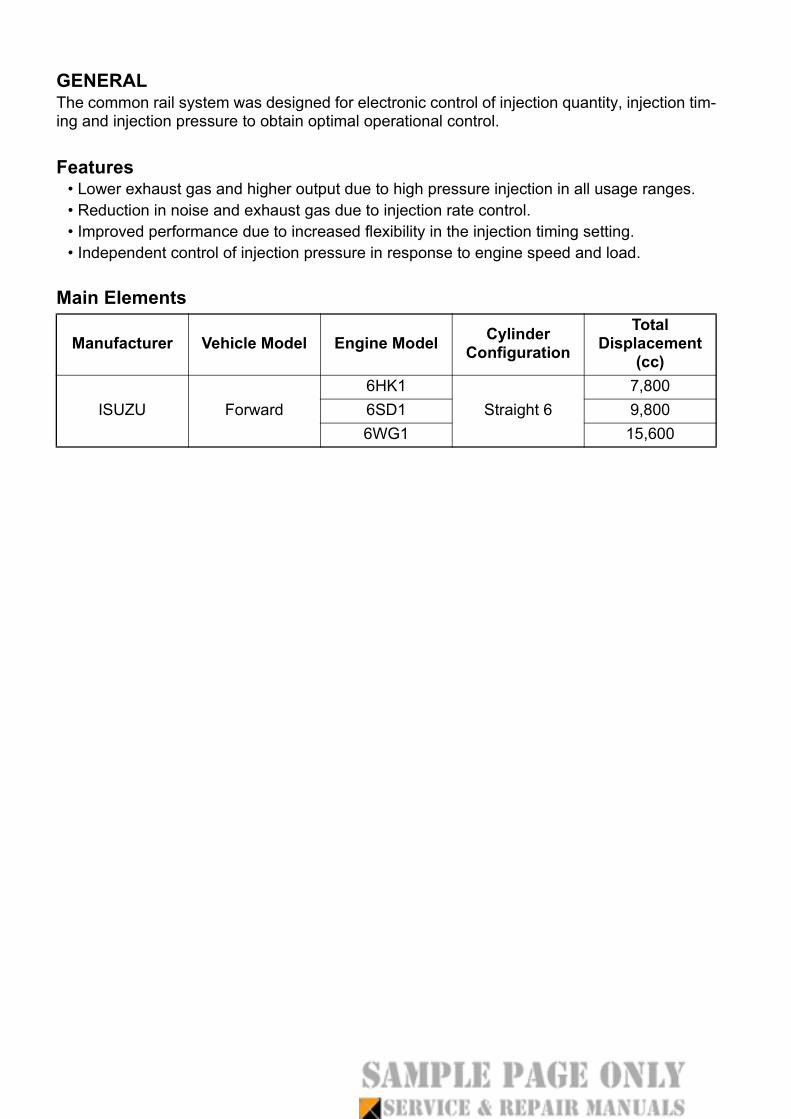
GENERALThe common rail system was designed for electronic control of injection quantity, injection tim-ing and injection pressure to obtain optimal operational control.
Features• Lower exhaust gas and higher output due to high pressure injection in all usage ranges.• Reduction in noise and exhaust gas due to injection rate control.• Improved performance due to increased flexibility in the injection timing setting.• Independent control of injection pressure in response to engine speed and load.
Main Elements
Manufacturer Vehicle Model Engine Model Cylinder Configuration
Total Displacement
(cc)
ISUZU Forward6HK1
Straight 67,800
6SD1 9,8006WG1 15,600
1
1. Outline1.1 System OutlineThis system also provides the following functions:
• A self-diagnosis and alarm function using computer to diagnose the system’s majorcomponents and alert the driver in the event of a problem.
• A fail-safe function to stop the engine, depending upon the location of the problem.• A backup function to change the fuel regulation method, thus enabling the vehicle to
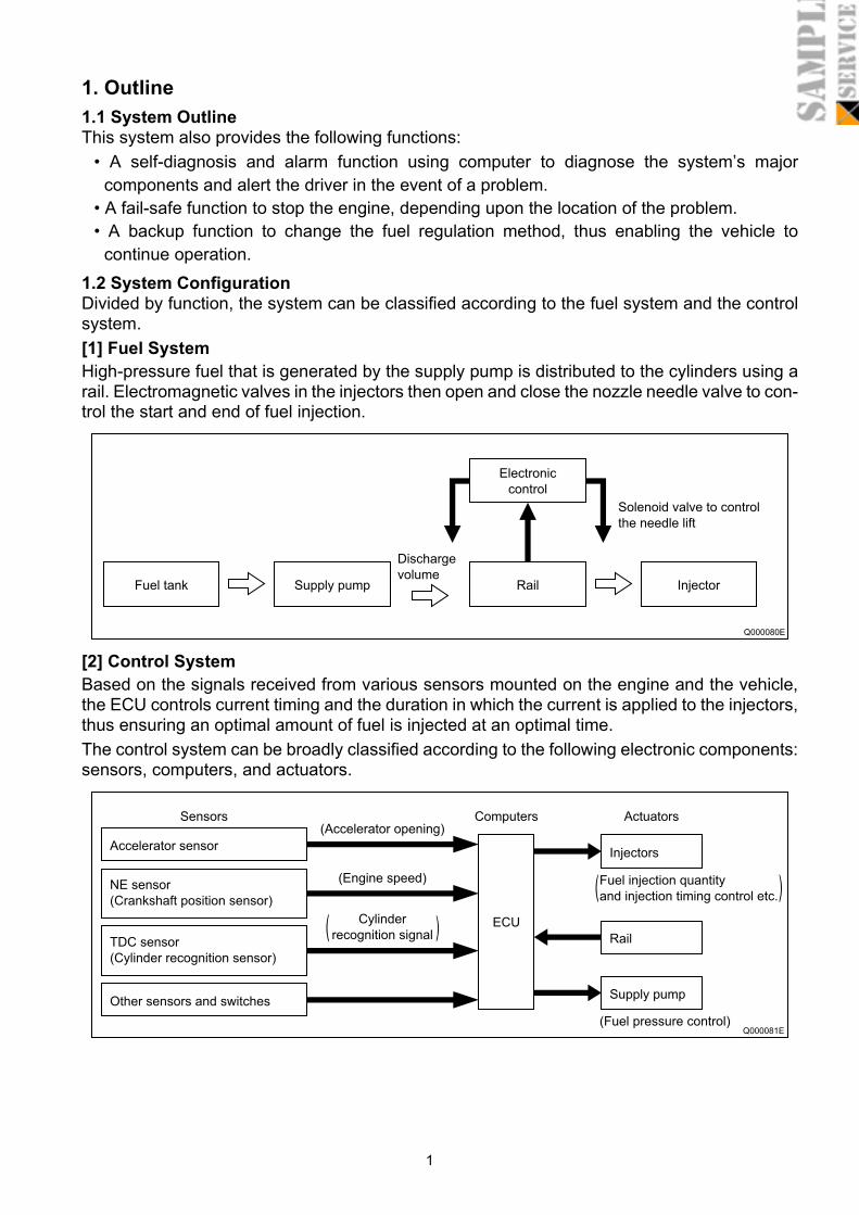
continue operation.1.2 System ConfigurationDivided by function, the system can be classified according to the fuel system and the controlsystem.[1] Fuel SystemHigh-pressure fuel that is generated by the supply pump is distributed to the cylinders using arail. Electromagnetic valves in the injectors then open and close the nozzle needle valve to con-trol the start and end of fuel injection.
[2] Control SystemBased on the signals received from various sensors mounted on the engine and the vehicle,the ECU controls current timing and the duration in which the current is applied to the injectors,thus ensuring an optimal amount of fuel is injected at an optimal time.The control system can be broadly classified according to the following electronic components:sensors, computers, and actuators.
Fuel tank Supply pump Rail
Electronic
control
Injector
Discharge
volume
Solenoid valve to control
the needle lift
Q000080E
Sensors Computers Actuators
Accelerator sensorInjectors
Rail
Supply pumpOther sensors and switches
NE sensor
(Crankshaft position sensor)
TDC sensor
(Cylinder recognition sensor)
(Accelerator opening)
(Engine speed)
Cylinder
recognition signal
Fuel injection quantity
and injection timing control etc.
(Fuel pressure control)
ECU( )
( )
Q000081E
Diesel Injection Pump
COMMON RAIL SYSTEM (CRS)
OPERATION
September, 2007
00400534E
SERVICE MANUAL

Table of Contents
Table of Contents
Operation Section
1. GENERAL DESCRIPTION1.1 Changes In Environment Surrounding The Diesel Engine . . . . . . . . . . . . . . . . . . . . . . . . . . . . . . . . . . . . . . . . 1-1
1.2 Demands On Fuel Injection System . . . . . . . . . . . . . . . . . . . . . . . . . . . . . . . . . . . . . . . . . . . . . . . . . . . . . . . . . 1-2
1.3 Types Of And Transitions In ECD (ELECTRONICALLY CONTROLLED DIESEL) Systems . . . . . . . . . . . . . . 1-3
1.4 Common Rail System Characteristics . . . . . . . . . . . . . . . . . . . . . . . . . . . . . . . . . . . . . . . . . . . . . . . . . . . . . . . . 1-4
1.5 Common Rail System And Supply Pump Transitions . . . . . . . . . . . . . . . . . . . . . . . . . . . . . . . . . . . . . . . . . . . . 1-5
1.6 Injector Transitions . . . . . . . . . . . . . . . . . . . . . . . . . . . . . . . . . . . . . . . . . . . . . . . . . . . . . . . . . . . . . . . . . . . . . . 1-5
1.7 Common Rail System Configuration . . . . . . . . . . . . . . . . . . . . . . . . . . . . . . . . . . . . . . . . . . . . . . . . . . . . . . . . . 1-6
2. COMMON RAIL SYSTEM OUTLINE2.1 Layout of Main Components . . . . . . . . . . . . . . . . . . . . . . . . . . . . . . . . . . . . . . . . . . . . . . . . . . . . . . . . . . . . . . . 1-7
3. SUPPLY PUMP DESCRIPTION3.1 HP0 Type. . . . . . . . . . . . . . . . . . . . . . . . . . . . . . . . . . . . . . . . . . . . . . . . . . . . . . . . . . . . . . . . . . . . . . . . . . . . . 1-12
3.2 HP2 Type. . . . . . . . . . . . . . . . . . . . . . . . . . . . . . . . . . . . . . . . . . . . . . . . . . . . . . . . . . . . . . . . . . . . . . . . . . . . . 1-18
3.3 HP3 Type. . . . . . . . . . . . . . . . . . . . . . . . . . . . . . . . . . . . . . . . . . . . . . . . . . . . . . . . . . . . . . . . . . . . . . . . . . . . . 1-27
3.4 HP4 Type. . . . . . . . . . . . . . . . . . . . . . . . . . . . . . . . . . . . . . . . . . . . . . . . . . . . . . . . . . . . . . . . . . . . . . . . . . . . . 1-41
4. RAIL DESCCRIPTION4.1 Rail Functions and Composition . . . . . . . . . . . . . . . . . . . . . . . . . . . . . . . . . . . . . . . . . . . . . . . . . . . . . . . . . . . 1-46
4.2 Component Part Construction and Operation . . . . . . . . . . . . . . . . . . . . . . . . . . . . . . . . . . . . . . . . . . . . . . . . . 1-46
5. INJECTOR DESCRIPTION5.1 General Description. . . . . . . . . . . . . . . . . . . . . . . . . . . . . . . . . . . . . . . . . . . . . . . . . . . . . . . . . . . . . . . . . . . . . 1-50
5.2 Injector Construction and Features . . . . . . . . . . . . . . . . . . . . . . . . . . . . . . . . . . . . . . . . . . . . . . . . . . . . . . . . . 1-51
5.3 Injector Operation . . . . . . . . . . . . . . . . . . . . . . . . . . . . . . . . . . . . . . . . . . . . . . . . . . . . . . . . . . . . . . . . . . . . . . 1-54
5.4 Injector Actuation Circuit . . . . . . . . . . . . . . . . . . . . . . . . . . . . . . . . . . . . . . . . . . . . . . . . . . . . . . . . . . . . . . . . . 1-54
5.5 Other Injector Component Parts . . . . . . . . . . . . . . . . . . . . . . . . . . . . . . . . . . . . . . . . . . . . . . . . . . . . . . . . . . . 1-56
6. DESCRIPTION OF CONTROL SYSTEM COMPONENTS6.1 Engine Control System Diagram (Reference) . . . . . . . . . . . . . . . . . . . . . . . . . . . . . . . . . . . . . . . . . . . . . . . . 1-59
6.2 Engine ECU (Electronic Control Unit) . . . . . . . . . . . . . . . . . . . . . . . . . . . . . . . . . . . . . . . . . . . . . . . . . . . . . . . 1-60
6.3 EDU (Electronic Driving Unit) . . . . . . . . . . . . . . . . . . . . . . . . . . . . . . . . . . . . . . . . . . . . . . . . . . . . . . . . . . . . . 1-60
6.4 Various Sensors . . . . . . . . . . . . . . . . . . . . . . . . . . . . . . . . . . . . . . . . . . . . . . . . . . . . . . . . . . . . . . . . . . . . . . . 1-61
7. CONTROL SYSTEM7.1 Fuel Injection Control. . . . . . . . . . . . . . . . . . . . . . . . . . . . . . . . . . . . . . . . . . . . . . . . . . . . . . . . . . . . . . . . . . . . 1-66
7.2 E-EGR System (Electric-Exhaust Gas Recirculation) . . . . . . . . . . . . . . . . . . . . . . . . . . . . . . . . . . . . . . . . . . . 1-76
7.3 Electronically Controlled Throttle (Not Made By DENSO). . . . . . . . . . . . . . . . . . . . . . . . . . . . . . . . . . . . . . . . 1-78
7.4 Exhaust Gas Control System . . . . . . . . . . . . . . . . . . . . . . . . . . . . . . . . . . . . . . . . . . . . . . . . . . . . . . . . . . . . . 1-79
7.5 DPF System (Diesel Particulate Filter) . . . . . . . . . . . . . . . . . . . . . . . . . . . . . . . . . . . . . . . . . . . . . . . . . . . . . . 1-80
7.6 DPNR SYSTEM (DIESEL PARTICULATE NOx REDUCTION). . . . . . . . . . . . . . . . . . . . . . . . . . . . . . . . . . . . 1-82
Table of Contents
8. DIAGNOSIS8.1 Outline Of The Diagnostic Function. . . . . . . . . . . . . . . . . . . . . . . . . . . . . . . . . . . . . . . . . . . . . . . . . . . . . . . . . 1-83
8.2 Diagnosis Inspection Using DST-1 . . . . . . . . . . . . . . . . . . . . . . . . . . . . . . . . . . . . . . . . . . . . . . . . . . . . . . . . . 1-83
8.3 Diagnosis Inspection Using The MIL (Malfunction Indicator Light) . . . . . . . . . . . . . . . . . . . . . . . . . . . . . . . . . 1-84
8.4 Throttle Body Function Inspection . . . . . . . . . . . . . . . . . . . . . . . . . . . . . . . . . . . . . . . . . . . . . . . . . . . . . . . . . . 1-86
9. END OF VOLUME MATERIALS9.1 Particulate Matter (PM) . . . . . . . . . . . . . . . . . . . . . . . . . . . . . . . . . . . . . . . . . . . . . . . . . . . . . . . . . . . . . . . . . . 1-87
9.2 Common Rail Type Fuel Injection System Development History And The World’s Manufacturers. . . . . . . . . 1-87
9.3 Higher Injection Pressure, Optimized Injection Rates, Higher Injection Timing Control Precision, Higher Injection
Quantity Control Precision. . . . . . . . . . . . . . . . . . . . . . . . . . . . . . . . . . . . . . . . . . . . . . . . . . . . . . . . . . . . . . . . 1-88
9.4 Image Of Combustion Chamber Interior . . . . . . . . . . . . . . . . . . . . . . . . . . . . . . . . . . . . . . . . . . . . . . . . . . . . . 1-90
Repair Section
1. DIESEL ENGINE MALFUNCTIONS AND DIAGNOSTIC METHODS (BASIC KNOWL-EDGE)1.1 Combustion State and Malfunction Cause . . . . . . . . . . . . . . . . . . . . . . . . . . . . . . . . . . . . . . . . . . . . . . . . . . . 2-91
1.2 Troubleshooting. . . . . . . . . . . . . . . . . . . . . . . . . . . . . . . . . . . . . . . . . . . . . . . . . . . . . . . . . . . . . . . . . . . . . . . . 2-92
2. DIAGNOSIS OVERVIEW2.1 Diagnostic Work Flow . . . . . . . . . . . . . . . . . . . . . . . . . . . . . . . . . . . . . . . . . . . . . . . . . . . . . . . . . . . . . . . . . . . 2-93
2.2 Inquiries . . . . . . . . . . . . . . . . . . . . . . . . . . . . . . . . . . . . . . . . . . . . . . . . . . . . . . . . . . . . . . . . . . . . . . . . . . . . . . 2-94
2.3 Non-Reoccurring Malfunctions . . . . . . . . . . . . . . . . . . . . . . . . . . . . . . . . . . . . . . . . . . . . . . . . . . . . . . . . . . . . 2-96
3. DTC READING (FOR TOYOTA VEHICLES)3.1 DST-2 . . . . . . . . . . . . . . . . . . . . . . . . . . . . . . . . . . . . . . . . . . . . . . . . . . . . . . . . . . . . . . . . . . . . . . . . . . . . . . . 2-98
3.2 DTC Check (Code Reading via the DST-2). . . . . . . . . . . . . . . . . . . . . . . . . . . . . . . . . . . . . . . . . . . . . . . . . . . 2-98
3.3 DTC Memory Erasure (via the DST-2) . . . . . . . . . . . . . . . . . . . . . . . . . . . . . . . . . . . . . . . . . . . . . . . . . . . . . . 2-98
4. TROUBLESHOOTING BY SYSTEM4.1 Intake System Diagnosis . . . . . . . . . . . . . . . . . . . . . . . . . . . . . . . . . . . . . . . . . . . . . . . . . . . . . . . . . . . . . . . . . 2-99
4.2 Fuel System Diagnosis . . . . . . . . . . . . . . . . . . . . . . . . . . . . . . . . . . . . . . . . . . . . . . . . . . . . . . . . . . . . . . . . . . 2-99
4.3 Basics of Electrical/Electronic Circuit Checks . . . . . . . . . . . . . . . . . . . . . . . . . . . . . . . . . . . . . . . . . . . . . . . . 2-102
5. TROUBLESHOOTING5.1 Troubleshooting According to Malfunction Symptom (for TOYOTA Vehicles). . . . . . . . . . . . . . . . . . . . . . . . 2-107
5.2 Other Malfunction Symptoms . . . . . . . . . . . . . . . . . . . . . . . . . . . . . . . . . . . . . . . . . . . . . . . . . . . . . . . . . . . . 2-122
6. DIAGNOSIS CODES (DTC)6.1 DTC Chart (Example) . . . . . . . . . . . . . . . . . . . . . . . . . . . . . . . . . . . . . . . . . . . . . . . . . . . . . . . . . . . . . . . . . . 2-124