service manual sky air r407c€“05 table of contents v 3 4 5 1 5 additional checks for...
TRANSCRIPT

ESIE03-05
Service ManualSky Air R407CRYEP~L-series
SVSV
p >
p <p <

ESIE03–05
3
4
5
1Table of Contents
1 Introduction
1.1 About This Manual .................................................................................. 1–vii1.2 Combination Overview: Outdoor Units of the Sky Air RYEP~L-Series ... 1–viii
Part 1 System Outline
1 General Outline: Outdoor Units
1.1 What Is in This Chapter?......................................................................... 1–31.2 RYEP71L7V1 and RYEP71L7W1........................................................... 1–41.3 RYEP100L7V1 and RYEP100L7W1....................................................... 1–61.4 RYEP125L7W1....................................................................................... 1–81.5 RYEP71L7V1, RYEP71L7W1, RYEP100L7V1, RYEP100L7W1 and
RYEP125L7W1:Installation and Service Space................................................................ 1–10
2 General Outline: Indoor Units
2.1 What Is in This Chapter?......................................................................... 1–13
3 Specifications
3.1 What Is in This Chapter?......................................................................... 1–153.2 RYEP71, RYEP100 and RYEP125......................................................... 1–16
4 Functional Diagrams
4.1 What Is in This Chapter?......................................................................... 1–174.2 RYEP71L7V1, RYEP71L7W1, RYEP100L7V1 and RYEP100L7W1 ..... 1–184.3 RYEP125L7W1....................................................................................... 1–204.4 Piping Components................................................................................. 1–21
Table of Contents i

ESIE03–05
3
1
4
5
5 Switch Box Layout
5.1 What Is in This Chapter? ........................................................................ 1–235.2 RYEP71L7V1and RYEP100L7V1........................................................... 1–245.3 RYEP71L7W1 and RYEP100L7W1........................................................ 1–255.4 RYEP125LW1......................................................................................... 1–26
6 Wiring Diagrams: Outdoor Units
6.1 What Is in This Chapter? ........................................................................ 1–276.2 RYEP71L7V1and RYEP100L7V1........................................................... 1–286.3 RYEP71L7W1 and RYEP100L7W1........................................................ 1–296.4 RYEP125L7W1....................................................................................... 1–30
7 PCB Layout
7.1 What Is in This Chapter? ........................................................................ 1–317.2 RYEP71L7V1, RYEP71L7W1, RYEP100L7V1, RYEP100L7W1and
RYEP125L7W1....................................................................................... 1–32
Part 2 Functional Description
1 General Functionality
1.1 What Is in This Chapter? ........................................................................ 2–31.2 Functions of Thermistors ........................................................................ 2–41.3 Operating Modes and Control Modes ..................................................... 2–61.4 Forced Operating Mode (Emergency Operation).................................... 2–71.5 Outdoor Unit Identification Function........................................................ 2–101.6 Thermostat Control ................................................................................. 2–111.7 Forced Thermostat OFF ......................................................................... 2–131.8 HPS and LPS Function ........................................................................... 2–141.9 Simulated Operation Function ................................................................ 2–151.10 Discharge Pipe Temperature Control ..................................................... 2–161.11 Gas Shortage Function ........................................................................... 2–171.12 Drain Pump Control ................................................................................ 2–181.13 Fan and Flap Operations ........................................................................ 2–201.14 Auto-Restart Function ............................................................................. 2–211.15 Using Conditions for Remote Controller Thermostat .............................. 2–221.16 Overcurrent Protection Function ............................................................. 2–231.17 Expansion Valve Control......................................................................... 2–24
ii Table of Contents

ESIE03–05
3
4
5
1
2 Overview of the cooling mode functions2.1 What Is in This Chapter?......................................................................... 2–272.2 Dry Keep Mode ....................................................................................... 2–282.3 Freeze-Up Function ................................................................................ 2–292.4 Outdoor Fan Starting Control in Cooling or Dry Keep Mode................... 2–342.5 Normal Outdoor Fan Control in Cooling Operation ................................. 2–352.6 High Pressure Protection Control in Cooling Operation.......................... 2–372.7 Condensation Avoidance Control............................................................ 2–38
3 Overview of the heating mode functions
3.1 What Is in This Chapter?......................................................................... 2–393.2 Defrost Control ........................................................................................ 2–403.3 Draft Avoidance Control 1 ....................................................................... 2–433.4 Draft Avoidance Control 2 ....................................................................... 2–453.5 4-way Valve Control ................................................................................ 2–463.6 Starting Outdoor Fan Control in Heating Mode....................................... 2–473.7 Normal Outdoor Fan Control in Heating Mode........................................ 2–483.8 Test run control ....................................................................................... 2–503.9 Discharge Pressure Control .................................................................... 2–51
Part 3 Troubleshooting
1 Troubleshooting
1.1 What Is in This Chapter?......................................................................... 3–31.2 Overview of General Problems ............................................................... 3–41.3 Procedure of Self-Diagnosis by Remote Controller ................................ 3–61.4 Checking with the Wireless Remote Controller Display .......................... 3–71.5 Self-Diagnosis by Wired Remote Controller............................................ 3–111.6 Remote Controller Display Malfunction Code and Contents................... 3–121.7 Troubleshooting with the Indoor Unit LEDs and the Remote Controller . 3–141.8 Troubleshooting with the Remote Controller: Outdoor Malfunctions....... 3–151.9 Troubleshooting with the Remote Controller: System Malfunctions........ 3–161.10 Overview of the Indoor Safety Devices ................................................... 3–171.11 Overview of the Outdoor Safety Devices ................................................ 3–181.12 Outdoor Safety Device: Thermal Protector Fan Motor............................ 3–191.13 Outdoor Safety Device: Reverse Phase Protector.................................. 3–201.14 Outdoor Safety Device: High-Pressure Switch ....................................... 3–211.15 Outdoor Safety Device: Low-Pressure Switch ........................................ 3–22
Table of Contents iii

ESIE03–05
3
1
4
5
2 Error Codes: Indoor Units
2.1 What Is in This Chapter? ........................................................................ 3–232.2 Malfunctioning Indoor PCB ..............................................................(A1) 3–242.3 Malfunctioning Drain Water Level System .......................................(A3) 3–252.4 Indoor Unit Fan Motor Lock .............................................................(A6) 3–272.5 Malfunctioning Drain System .......................................................... (AF) 3–292.6 Malfunctioning Capacity Setting .......................................................(AJ) 3–312.7 Thermistor Abnormality ..........................................................(C4 or C9) 3–332.8 Malfunctioning Remote Controller Air Thermistor ............................ (CJ) 3–35
3 Error Codes: Outdoor Units
3.1 What Is in This Chapter? ........................................................................ 3–373.2 Activation of Safety Device ..............................................................(E0) 3–383.3 Failure of Outdoor Unit PC Board (E1) ................................................... 3–433.4 Abnormal High Pressure (Detected by the HPS) .............................(E3) 3–443.5 Abnormal Low Pressure (Detected by the LPS) ..............................(E4) 3–463.6 Compressor Overcurrent .................................................................(E6) 3–483.7 Malfunctioning Electronic Expansion Valve .....................................(E9) 3–503.8 Malfunctioning in Discharge Pipe Temperature ...............................(F3) 3–523.9 Malfunctioning HPS ........................................................................ (H3) 3–543.10 Malfunctioning Outdoor Thermistor System .................................... (H9) 3–553.11 Malfunctioning Discharge Pipe Thermistor System ......................... (J3) 3–563.12 Malfunctioning Heat Exchanger Thermistor System ........................ (J6) 3–573.13 Abnormal Heat Exchanging Temperature (F6) ....................................... 3–583.14 Malfunction of Current Sensor System (J2) ............................................ 3–593.15 Failure of Capacity Setting (PJ) .............................................................. 3–61
4 Error Codes: System Malfunctions
4.1 What Is in This Chapter? ........................................................................ 3–634.2 Gas Shortage Detection .................................................................. (U0) 3–644.3 Reverse Phase ............................................................................... (U1) 3–654.4 Transmission Error between Indoor and Outdoor Unit ......... (U4 or UF) 3–674.5 Transmission Error between Indoor Unit and Remote Controller ... (U5) 3–694.6 Transmission Error between MAIN Remote Controller
and SUB Remote Controller ........................................................... (U8) 3–704.7 Malfunctioning Field Setting Switch ................................................ (UA) 3–71
iv Table of Contents

ESIE03–05
3
4
5
1
5 Additional Checks for Troubleshooting5.1 What Is in This Chapter?......................................................................... 3–735.2 Indoor Unit: Checking the Fan Motor Hall IC .......................................... 3–745.3 Indoor Unit: Checking the Power Supply Wave Form............................. 3–755.4 Outdoor Unit: Checking the Refrigerant System..................................... 3–765.5 Outdoor unit: Checking the Installation Condition ................................... 3–775.6 Outdoor Unit: Checking the Discharge Pressure .................................... 3–785.7 Outdoor Unit: Checking the Expansion Valve ......................................... 3–795.8 Checking the Thermistors ....................................................................... 3–805.9 R1T and R2T: Resistance Conversion Table (Ambient & Coil Sensor) .. 3–815.10 R3T: Resistance Conversion Table (Discharge Pipe Sensor) ................ 3–825.11 Evaluation of abnormal high pressure..................................................... 3–835.12 Evaluation of abnormal low pressure ...................................................... 3–845.13 Check for Clogged Points ....................................................................... 3–85
Part 4 Commissioning and Test Run
1 Pre-Test Run Checks
1.1 What Is in This Chapter?......................................................................... 4–31.2 Test Run Checks..................................................................................... 4–41.3 Setting the Wireless Remote Controller .................................................. 4–5
2 Field settings
2.1 What Is in This Chapter?......................................................................... 4–92.2 How to Change the Field Settings with the Wired Remote Controller..... 4–102.3 How to Change the Field Settings with the Wireless Remote Controller 4–122.4 Overview of the Field Settings of the Indoor Units .................................. 4–132.5 Overview of the Factory Settings of the Indoor Units.............................. 4–142.6 Setting the Ceiling Height........................................................................ 4–152.7 Setting the Filter Counter ........................................................................ 4–162.8 MAIN/SUB Setting when Using Two Remote Controllers ....................... 4–172.9 Setting the Centralized Group No. .......................................................... 4–182.10 Field settings when using a spare part PCB of Sky-Air L-series
outdoor unit ............................................................................................. 4–202.11 The Field Setting Levels.......................................................................... 4–232.12 Overview of the Field Settings: RYEP71-125L ....................................... 4–262.13 Jumpers .................................................................................................. 4–282.14 DIP switch DS1 ....................................................................................... 4–292.15 DIP switch DS2 ....................................................................................... 4–30
3 Test Run and Operation Data
3.1 General Operation Data .......................................................................... 4–343.2 RYEP71L7V1, RYEP71L7W1, RYEP100L7V1, RYEP100L7W1 and
RYEP125L7W1....................................................................................... 4–36
Table of Contents v

ESIE03–05
3
1
4
5
Part 5 Disassembly and Maintenance
1 Disassembly and Maintenance: Outdoor Units
1.1 What Is in This Chapter? ........................................................................ 5–31.2 RYEP71L7V1 and RYEP71L7W1........................................................... 5–41.3 RYEP100L7V1 and RYEP100L7W1....................................................... 5–61.4 RYEP125L7W1....................................................................................... 5–8
vi Table of Contents

ESIE03–05 Introduction
Part 0
3
4
5
1 Introduction
1.1 About This Manual
Target group This service manual is intended for and should only be used by qualified engineers.
Purpose of this manual
This service manual contains all the information you need to do the necessary repair and maintenance tasks for the Sky Air RYEP~L-series room air conditioners.
Five parts This service manual consists of an introduction, five parts and an index:
Introduction overview
The introduction contains the following topics:
Part See page
Part 1–System Outline 1–1
Part 2–Functional Description 2–1
Part 3–Troubleshooting 3–1
Part 4–Commissioning and Test Run 4–1
Part 5–Disassembly and Maintenance 5–1
Topic See page
1.2–Combination Overview: Outdoor Units of the Sky Air RYEP~L-Series viii
vii

Introduction ESIE03–05
3
1
4
5
1.2 Combination Overview: Outdoor Units of the Sky Air RYEP~L-Series
Introduction In the tables in this section:
“P” stands for pair combination.
“T” stands for twin, triple or double twin combination.
FHYCP, FHYKP and FHYP
The table below contains the possible combinations between indoor units (FHYCP, FHYKP and FHYP) and outdoor units of the Sky Air RYEP~L-series.
FUYP, FAYP, FHYBP, FDYMP and FDYP
The table below contains the possible combinations between indoor units (FUYP, FAYP, FHYBP, FDYMP and FDYP) and outdoor units of the Sky Air RYEP~L-series.
FH
YC
P35
B7V
1
FH
YC
P45
B7V
1
FH
YC
P60
B7V
1
FH
YC
P71
B7V
1
FH
YC
P10
0B7V
1
FH
YC
P12
5B7V
1
FH
YK
P35
BV
17
FH
YK
P45
BV
17
FH
YK
P60
BV
17
FH
YK
P71
BV
17
FH
YP
35B
V1
FH
YP
45B
V1
FH
YP
60B
V1
FH
YP
71B
V1
FH
YP
100B
V1
FH
YP
125B
V1
HP
RYEP71L7V1 T — — P — — T — — P T — — P — —
RYEP71L7W1 T — — P — — T — — P T — P — —
RYEP100L7V1 T T T T P — T T T T T T T T P —
RYEP100L7W1 T T T T P — T T T T T T T T P —
RYEP125L7W1 T T T T — P T T T T T T T T — P
Outdoor unit
Indoor unit
FU
YP
71B
V17
FU
YP
100B
V17
FU
YP
125B
V17
FAY
P71
LV1
FAY
P10
0BV
1
FH
YB
P35
B7V
1
FH
YB
P45
B7V
1
FH
YB
P60
B7V
1
FH
YB
P71
B7V
1
FH
YB
P10
0B7V
1
FH
YB
P12
5B7V
1
FD
YM
P71
L7V
1
FD
YM
P10
0L7V
1
FD
YM
P12
5L7V
1
FD
YP
125B
7V1
HP
RYEP71L7V1 P — — P — T — — P — — P — — —
RYEP71L7W1 P — — P — T — — P — — P — — —
RYEP100L7V1 T P — T P T T T T P — T P — —
RYEP100L7W1 T P — T P T T T T P — T P — —
RYEP125L7W1 T — P T — T T T T — P T — P P
Outdoor unit
Indoor unit
viii

ESIE03–05
4
3
4
5
1
Part 1System Outline
What is in this part? This part contains the following chapters:
Chapter See page
1–General Outline: Outdoor Units 1–3
2–General Outline: Indoor Units 1–13
3–Specifications 1–15
4–Functional Diagrams 1–17
5–Switch Box Layout 1–23
6–Wiring Diagrams: Outdoor Units 1–27
7–PCB Layout 1–31
Part 1 – System Outline 1–1

ESIE03–05
3
11
5
1–2 Part 1 – System Outline

ESIE03–05 General Outline: Outdoor Units
1
Part 13
4
5
1 General Outline: Outdoor Units
1.1 What Is in This Chapter?
Introduction This chapter contains the following information on the outdoor units:
Outlook and dimensions
Installation and service space
Components.
General outline This chapter contains the following general outlines:
General outline See page
1.2–RYEP71L7V1 and RYEP71L7W1 1–4
1.3–RYEP100L7V1 and RYEP100L7W1 1–6
1.4–RYEP125L7W1 1–8
1.5–RYEP71L7V1, RYEP71L7W1, RYEP100L7V1, RYEP100L7W1 and RYEP125L7W1: Installation and Service Space
1–10
Part 1 – System Outline 1–3

General Outline: Outdoor Units ESIE03–05
3
11
4
5
1.2 RYEP71L7V1 and RYEP71L7W1
Outlook and dimensions
The illustration below shows the outlook and the dimensions of the unit (mm).
Installation and service space
See page 1–10.
1–4 Part 1 – System Outline

ESIE03–05 General Outline: Outdoor Units
3
1
4
5
Components The table below contains the different components of the unit.
No. Component
1 Gas pipe connection
2 Liquid pipe connection
3 Service port (inside the unit)
4 Grounding terminal M5 (inside the switch box)
5 Refrigerant piping intake
6 Power supply wiring intake
7 Control wiring intake
8 Drain outlet
Part 1 – System Outline 1–5

General Outline: Outdoor Units ESIE03–05
3
11
4
5
1.3 RYEP100L7V1 and RYEP100L7W1
Outlook and dimensions
The illustration below shows the outlook and the dimensions of the unit (mm).
Installation and service space
See page 1–10.
1–6 Part 1 – System Outline

ESIE03–05 General Outline: Outdoor Units
3
1
4
5
Components The table below contains the different components of the unit.
No. Component
1 Gas pipe connection
2 Liquid pipe connection
3 Service port (inside the unit)
4 Grounding terminal M5 (inside the switch box)
5 Refrigerant piping intake
6 Power supply wiring intake
7 Control wiring intake
8 Drain outlet
Part 1 – System Outline 1–7

General Outline: Outdoor Units ESIE03–05
3
11
4
5
1.4 RYEP125L7W1
Outlook and dimensions
The illustration below shows the outlook and the dimensions of the unit (mm).
Installation and service space
See page 1–10.
.
1–8 Part 1 – System Outline

ESIE03–05 General Outline: Outdoor Units
3
1
4
5
Components The table below contains the different components of the unit.
No. Component
1 Gas pipe connection
2 Liquid pipe connection
3 Service port (inside the unit)
4 Grounding terminal M5 (inside the switch box)
5 Refrigerant piping intake
6 Power supply wiring intake
7 Control wiring intake
8 Drain outlet
Part 1 – System Outline 1–9

General Outline: Outdoor Units ESIE03–05
3
11
4
5
1.5 RYEP71L7V1, RYEP71L7W1, RYEP100L7V1, RYEP100L7W1 and RYEP125L7W1:Installation and Service Space
Non stacked The illustrations and table below show the required installation and service space (mm). The values in brackets are for the 100 and 125 class.
Suction side obstacle
Discharge side obstacle
Left side obstacle
Right side obstacle
Top side obstacle
Obstacle is present
In these cases, close the bottom of the installation frame to prevent discharged air from being bypassed
In these cases, only 2 units can be installed
1
2
This situation is not allowed
1–10 Part 1 – System Outline

ESIE03–05 General Outline: Outdoor Units
3
1
4
5
Stacked The illustration below shows the required installation and service space (mm). The values in brackets are for the 100 and 125 class.
Do not stack more than one unit.
± 100 mm is required for the drain pipe.
Seal A in order to prevent outlet air from bypassing.
Multiple rows The illustration below shows the required installation and service space (mm). The values in brackets are for the 100 and 125 class.
With obstacles in front of the air outlet side With obstacles in front of the air inlet side
One unit per row Multiple units per row
installation impossible
Part 1 – System Outline 1–11

General Outline: Outdoor Units ESIE03–05
3
11
4
5
1–12 Part 1 – System Outline

ESIE03–05 General Outline: Indoor Units
1
Part 13
4
5
2 General Outline: Indoor Units
2.1 What Is in This Chapter?
Introduction This chapter contains the following information on the indoor units:
Outlook and dimensions
Installation and service space
Components.
General outline For the General Outline from the indoor units, please refer to the Service manual for Sky Air L-series ESIE03-04.
Part 1 – System Outline 1–13

General Outline: Indoor Units ESIE03–05
3
11
4
5
1–14 Part 1 – System Outline

ESIE03–05 Specifications
1
Part 13
4
5
3 Specifications
3.1 What Is in This Chapter?
Introduction This chapter contains the following information:
Technical specifications
Electrical specifications.
Options For possible options, refer to OHE03-2 or the installation manual.
Outdoor units This chapter contains the following specifications:
Specifications See page
3.2–RYEP71, RYEP100 and RYEP125 1–16
Part 1 – System Outline 1–15

Specifications ESIE03–05
3
11
4
5
3.2 RYEP71, RYEP100 and RYEP125
Technical specifications
The table below contains the technical specifications.
Electrical specifications
The table below contains the electrical specifications.
Specification RYEP71L7V1 RYEP71L7W1 RYEP100L7V1 RYEP100L7W1 RYEP125L7W1
Compressor
Model x No. ZR34K3E-PFJ ZR34K3E-TFD ZR47K3E-PFJ ZR47K3E-TFD JT160FA-YE
Type Hermetically sealed scroll type
Crankcase heater 33 W —
Refrigerant oil type 3MAWPOE DAPHNE FVC68D
No. x motor output 1 x 2110 W 1 x 2920 W 1 x 3750 W
Speed —
Oil charge 1242 cc 1360 cc 1500 cc
Outdoor
Heat exchanger
Length 859 mm
Rows x stages x fin pitch 2 x 34 x 2.0 mm 2 x 52 x 2.0 mm
No of passes 6 10
Face area 0.364 m∑ 0.983 m∑
Tube type HI-XSS Cooling tube
Fin type Non sym. waffle louvre
Empty tubeplate hole 0
No. of fans 1 2
Fan
Nominal air flow (230 V) cooling 48 m∏/min 55 m∏/min 89 m∏/min
Nominal air flow (230 V) heating 43 m∏/min 50 m∏/min 80 m∏/min
Fan motor model P47L11S P47L11S X2
Fan speed 3 steps
Refrigerant circuitType R407C
Charge 2.2 kg 3.5 kg
Safety and functional devices See page 1–17 and 3–18
Heat insulation Both liquid and gas pipes
Weight 75 kg 73 kg 93 kg 91 kg 106 kg
Specification RYP71L7V1 RYP71L7W1 RYP100L7V1 RYP100L7W1 RYP125L7W1
Unit Phase 1~ 3N~ 1~ 3N~ 3N~
Voltage 230 V 400 V 230 V 400 V 400 V
Frequency 50 Hz
No. of wire connections 3 wires for power supply (including earth wire)
5 wires for power supply (including earth wire)
4 wires for connection with indoor (including earth wire)
3 wires for power supply (including earth wire)
4 wires for connection with indoor (including earth wire)
5 wires for power supply (including earth wire)
4 wires for connection with indoor (including earth wire)
5 wires for power supply (including earth wire)
4 wires for connection with indoor (including earth wire)
4 wires for connec-tion with indoor (including earth wire)
Power supply intake Outdoor unit only
Compressor Phase 1~ 3~ 1~ 3~
Voltage 230 V 400 V 230 V 400 V
Starting method Direct
Fan motor Phase 1~
Voltage 230 V
No. of motors x output 1 x 65 W 90 W 85 + 65 W
1–16 Part 1 – System Outline

ESIE03–05 Functional Diagrams
1
Part 13
4
5
4 Functional Diagrams
4.1 What Is in This Chapter?
Introduction This chapter contains the following information:
Functional diagrams
Pipe connection diameters.
Functional diagrams
This chapter contains the following functional diagrams:
Functional diagram See page
4.2–RYEP71L7V1, RYEP71L7W1, RYEP100L7V1 and RYEP100L7W1 1–18
4.3–RYEP125L7W1 1–20
4.4–Piping Components 1–21
Part 1 – System Outline 1–17

Functional Diagrams ESIE03–05
3
11
4
5
4.2 RYEP71L7V1, RYEP71L7W1, RYEP100L7V1 and RYEP100L7W1
Functional diagram RYEP71L7V1 and RYEP71L7W1
The illustration below shows the functional diagram of the refrigeration circuit.
18 6
8
16
15a 15a
15a 15a
20
20
17
8
5a
15a
12
8
4
17
11
7
1011
Liqu
id
pipi
ngG
as
pipi
ng
2b & 3
HeatingCooling
21
1–18 Part 1 – System Outline

ESIE03–05 Functional Diagrams
3
1
4
5
Functional diagram RYEP100L7V1 and RYEP100L7W1
The illustration below shows the functional diagram of the refrigeration circuit.
Components For a description of the components, see ’Piping Components’ on page 1–21.
Pipe connection diameters
The table below contains the refrigerant pipe connection diameters.
18 6
8
16
15a 15a
15a 15a
20
20
17
8
5a
15a
128
4
17
11
7
1011
Liqu
id
pipi
ngG
as
pipi
ng
2b & 3
HeatingCooling
21
Model ∅ Gas pipe (flare) ∅ Liquid pipe (flare)
RYEP71L7V1 15.9 mm 9.5 mm
RYEP71L7W1
RYEP100L7V1 19.1 mm
RYEP100L7W1
Part 1 – System Outline 1–19

Functional Diagrams ESIE03–05
3
11
4
5
4.3 RYEP125L7W1
Functional diagram The illustration below shows the functional diagram of the refrigeration circuit.
Components For a description of the components, see ’Piping Components’ on page 1–21.
Pipe connection diameters
The table below contains the refrigerant pipe connection diameters.
18 6
8
16
15a
15a 15a
20
17
8
15a
128
4
11
7
1011
Liqu
id
pipi
ngG
as
pipi
ng
2b & 3
HeatingCooling
15a
13
Model ∅ Gas pipe (flare) ∅ Liquid pipe (flare)
RYEP125L7W1 19.1 mm 9.5 mm
1–20 Part 1 – System Outline

ESIE03–05 Functional Diagrams
3
1
4
5
4.4 Piping Components
Components The table below contains the different components of the functional diagrams.
No. Component Function / remark
1a Flare connection See pipe connection diameter.
1b Flange connection
2a Liquid stop valve The liquid stop valve is used as shut-off valve in case of a pump-down.
2b Liquid stop valve with service port
3 Gas stop valve with service port
The gas stop valve is used as shut-off valve in case of a pump-down.
4 Compressor The compressor can restart after 3 min from last stop.
5a Capillary tube The capillary tube allows pressure equalization during a compressor OFF-cycle.
5b The capillary tube expands the liquid to enable evaporation in the evaporator.
6 Electronic expan-sion valve
The expansion valve expands the liquid to enable evaporation in the evaporator. The opening degree is controlled to obtain the optimum discharge temperature.
7 Heat exchanger The heat exchanger is of the multi louvre fin type. Hi-X -tubes and coated waffle louvre fins are used.
8 Filter The filter is used to collect impurities, which may enter the system during installation and is also used to avoid blockage of the capillaries and other fine mechanical parts of the unit.
9 Accumulator The accumulator is used to separate the gas from the liquid in order to protect the compressor against liquid pumping.
10 Liquid receiver The liquid receiver is used to make sure only completely liquefied refrigerant is sent to the expan-sion valve. It is also used as a container in which surplus refrigerant is stored.
11 Check valve with service port
The check valve allows you to connect a gauge.
12 Low-pressure switch The low-pressure switch stops the operation of the unit when the pressure becomes abnormally low.
13 High-pressure switch The high-pressure switch stops the operation of the unit when the pressure becomes abnormally high.
14 Propeller fan and fan motor
The propeller fan creates air displacement across the heat exhanger.
15a One-way valve The one-way valve is used to force the refrigerant liquid to flow through the receiver and the expansion valve in the same direction both in cooling and heating.
15b The one-way valve is used to release overpressure in the liquid receiver during stand-still.
16 4-way valve
(reversing solenoid valve)
The 4-way valve is used to select refrigerant flow in cooling or heating mode.
When the 4-way valve switches from ON to OFF, a timer starts counting up to 150 as soon as the cooling or defrosting operation is stopped. This delay time is to eliminate the switching sound.
17 Muffler The muffler is used to absorb the refrigerant noise from the compressor.
18 Solenoid valve Y1S: Capacity control solenoid valve
Y3S: Liquid injection solenoid valve
SV: Solenoid valve (Purge liquid receiver)
19 Thermistor R1T: Air thermistor
R2T: Coil thermistor
R3T: Discharge pipe thermistor
20 Strainer
21 Discharge pressure regulator
Part 1 – System Outline 1–21

Functional Diagrams ESIE03–05
3
11
4
5
1–22 Part 1 – System Outline

ESIE03–05 Switch Box Layout
1
Part 13
4
5
5 Switch Box Layout
5.1 What Is in This Chapter?
Introduction This chapter shows the switch box components.
Outdoor units This chapter contains the following switch box layouts:
Switch box layout See page
5.2–RYEP71L7V1and RYEP100L7V1 1–24
5.3–RYEP71L7W1 and RYEP100L7W1 1–25
5.4–RYEP125LW1 1–26
Part 1 – System Outline 1–23

Switch Box Layout ESIE03–05
3
11
4
5
5.2 RYEP71L7V1and RYEP100L7V1
Switch box The illustration below shows the switch box layout.
Components The table below contains the components of the switch box.
T1R
K1M
X1M
C1R
PCB
X2M
F2U
F1U
T1R
K1M
X1M
C1R
PCB
X2M
F2U
F1U
Symbol Component
T1R Transformer
C1R Fan motor capacitor
K1M Magnetic contactor
X1M Terminal strip
X2M Terminal strip interconnection wiring
F1U/F2U Fuses
PCB Printed circuit board
1–24 Part 1 – System Outline

ESIE03–05 Switch Box Layout
3
1
4
5
5.3 RYEP71L7W1 and RYEP100L7W1
Switch box The illustration below shows the switch box layout.
Components The table below contains the components of the switch box.
C1R PCB
X3M
T1R
K1M
X2M
F2U
F1U
X1M
Symbol Component
X1M Terminal strip
X2M Terminal strip interconnection wiring
X3M Terminal strip
F1U/F2U Fuses
PCB Printed circuit board
T1R Transformer
C1R Fan motor capacitor
K1M Magnetic contactor
Part 1 – System Outline 1–25

Switch Box Layout ESIE03–05
3
11
4
5
5.4 RYEP125LW1
Switch box The illustration below shows the switch box layout.
Components The table below contains the components of the switch box.
T1R
K1M
X1M
C1R
PCB
X2M
F2U
F1U
X3M
C2R
Symbol Component
T1R Transformer
C1R Fan motor capacitor 1
C2R Fan motor capacitor 2
K1M Magnetic contactor
X1M Terminal strip
X2M Terminal strip interconnection wiring
X3M Terminal strip
F1U/F2U Fuses
PCB Printed circuit board
1–26 Part 1 – System Outline

ESIE03–05 Wiring Diagrams: Outdoor Units
1
Part 13
4
5
6 Wiring Diagrams: Outdoor Units
6.1 What Is in This Chapter?
Introduction This chapter contains the wiring diagrams of the outdoor units.
Wiring diagrams This chapter contains the following wiring diagrams:
Wiring diagram See page
6.2–RYEP71L7V1and RYEP100L7V1 1–28
6.3–RYEP71L7W1 and RYEP100L7W1 1–29
6.4–RYEP125L7W1 1–30
Part 1 – System Outline 1–27

Wiring Diagrams: Outdoor Units ESIE03–05
3
11
4
5
6.2 RYEP71L7V1and RYEP100L7V1
Wiring diagram The illustration below shows the wiring diagram of the unit.
1–28 Part 1 – System Outline

ESIE03–05 Wiring Diagrams: Outdoor Units
3
1
4
5
6.3 RYEP71L7W1 and RYEP100L7W1
Wiring diagram The illustration below shows the wiring diagram of the unit.
Part 1 – System Outline 1–29

Wiring Diagrams: Outdoor Units ESIE03–05
3
11
4
5
6.4 RYEP125L7W1
Wiring diagram The illustration below shows the wiring diagram of the unit.
1–30 Part 1 – System Outline

ESIE03–05 PCB Layout
1
Part 13
4
5
7 PCB Layout
7.1 What Is in This Chapter?
Introduction This chapter contains the following information:
It describes which unit uses which PCB types
It shows the PCB connectors.
PCB layouts This chapter contains the following PCB layouts:
PCB layout See page
7.2–RYEP71L7V1, RYEP71L7W1, RYEP100L7V1, RYEP100L7W1and RYEP125L7W1
1–32
Part 1 – System Outline 1–31

PCB Layout ESIE03–05
3
11
4
5
7.2 RYEP71L7V1, RYEP71L7W1, RYEP100L7V1, RYEP100L7W1and RYEP125L7W1
PCB The illustration below shows the PCB connectors.
Connectors The table below describes the PCB connectors.
X14A
X24A
X40A
X7AX15AX12A
X9A X11A X25AX8A X27A
X22A
X10AX26A
X6AX5A
X4A X1A
Connector Connected to Description
X4A R1T Air thermistor
X5A R2T Coil thermistor
X6A R3T Discharge pipe thermistor
X7A-X1A T1R Transformer (220-240V/24,9V)
X8A K1M Magnetic contactor (M1C)
X9A S1PH High pressure switch
X10A S1PL Low pressure switch
X11A Q1M Thermo switch (M1F)
X12A Q2M Thermo switch (M2F)
X14A M2F Fan motor 2
X15A M1F Fan motor 1
X22A Y1S 4-way valve
X24A Y1E Electronic expansion valves
X25A E1HC Crankcase heater
X26A — Connector for capacity setting adapter
X27A Y2S Solenoid valve
X40A — Connector for VRV service checker
1–32 Part 1 – System Outline
ESIE03–05
4
3
4
5
2
Part 2Functional Description
What is in this part? This part contains the following chapters:
Chapter See page
1–General Functionality 2–3
2–Overview of the cooling mode functions 2–27
3–Overview of the heating mode functions 2–39
Part 2 – Functional Description 2–1

ESIE03–05
3
1
2
5
2–2 Part 2 – Functional Description

ESIE03–05 General Functionality
1
Part 23
4
5
2
1 General Functionality
1.1 What Is in This Chapter?
Introduction This chapter contains information on the functions used to control the system. Understanding these functions is vital when diagnosing a malfunction that is related to the functional control.
Overview This chapter contains the following topics:
Topic See page
1.2–Functions of Thermistors 2–4
1.3–Operating Modes and Control Modes 2–6
1.4–Forced Operating Mode (Emergency Operation) 2–7
1.5–Outdoor Unit Identification Function 2–10
1.6–Thermostat Control 2–11
1.7–Forced Thermostat OFF 2–13
1.8–HPS and LPS Function 2–14
1.9–Simulated Operation Function 2–15
1.10–Discharge Pipe Temperature Control 2–16
1.11–Gas Shortage Function 2–17
1.12–Drain Pump Control 2–18
1.13–Fan and Flap Operations 2–20
1.14–Auto-Restart Function 2–21
1.15–Using Conditions for Remote Controller Thermostat 2–22
1.16–Overcurrent Protection Function 2–23
1.17–Expansion Valve Control 2–24
Part 2 – Functional Description 2–3

General Functionality ESIE03–05
3
1
2
4
5
1.2 Functions of Thermistors
Locating the thermistors
The thermistors on the illustration below are used to control the system. This control secures a proper operation and prevents problems of the unit.
Functions of the thermistors
The table below contains the thermistor functions of the large h/p.
Ther-mistor
LocationWiring symbol
Mode Function
1 Indoor heat exchanger
R2T Cooling Optimise discharge temp. (evap. temp.)
Freeze-up thermostat
Heat-ing
Optimise discharge temp. (cond. temp.)
Integral capacity calculation (to determine defrost)
Hot start indoor fan
Peak cut-off
Outdoor unit fan control
2 Indoor air return
R1T Cooling Thermostat control
Start-up control expansion valve and outdoor unit fan
Outdoor fan speed control
Heat-ing
Thermostat control
Start-up control expansion valve and outdoor unit fan
Integral capacity calculation (to determine defrost)
Peak cut-off
2–4 Part 2 – Functional Description

ESIE03–05 General Functionality
3
2
4
5
1
3 Outdoorheat exchanger
R2T Cooling Optimise discharge temp. (cond. temp.)
Outdoor fan speed control (O.L.)
Heat-ing
Optimise discharge temp. (evap. temp.)
Defrost start/stop
4 Outdoor air return
R1T Cooling Outdoor fan speed control
Start-up control expansion valve and outdoor unit fan
Heat-ing
Integral capacity calculation (to determine defrost)
Start-up control expansion valve and outdoor unit fan
5 Discharge pipe com-pressor
R3T Cooling Cooling overload
Check refrigerant shortage/too much refrigerant
Expansion valve control
Heat-ing
Heating overload
Check refrigerant shortage/too much refrigerant
Expansion valve control
Ther-mistor
LocationWiring symbol
Mode Function
Part 2 – Functional Description 2–5

General Functionality ESIE03–05
3
1
2
4
5
1.3 Operating Modes and Control Modes
Operating modes The two operating modes are:
Normal operating mode
Forced operating mode.
Control modes The table below contains the different control modes.
Operating mode Control mode
Normal operating mode Cooling
Dry keep
Heating
Defrosting (automatic)
Freeze-up
Pump down
Stop mode
Forced operating mode Forced cooling
Forced heating
Forced defrosting
2–6 Part 2 – Functional Description

ESIE03–05 General Functionality
3
2
4
5
1
1.4 Forced Operating Mode (Emergency Operation)Applicable units The forced operating mode is applicable for the following units:
Purpose The table below describes the purpose of the forced operating mode.
Before switching Before moving the switches to emergency operation, make sure to turn OFF the power firstly.
During emergency operation, do not attempt to operate the equipment from the remote controller. The remote controller displays 88 while the emergency operation is active on the indoor unit.
Switching To switch to forced operating mode, proceed as follows:
Model type For this unit, you can go to...
RYEP71-125L7 Forced cooling mode
Forced heating mode
If... Then...
Remocon is malfunctioning, or
Indoor PCB is off line, or
Outdoor PCB is off line
Forced operating mode can be used to go to cooling or heat-ing. In forced operating mode, the compressor is forced to operate until the malfunctioning indoor or outdoor PCB is back online.
Step Action
1 Turn OFF the power.
2 Switch ON the emergency switch (SS1) on the indoor PCB.
3 Switch ON the emergency switch on the outdoor PCB.
Switch 2 is not applicable for the c/o units.
(SS1) normalemergency
ON COOL
OFF HEAT
ON
1 2
Part 2 – Functional Description 2–7

General Functionality ESIE03–05
3
1
2
4
5
Before switching back
Before moving the switches back to normal operating mode, make sure to turn OFF the power firstly.
Starting conditions You can operate the system manually by changing the emergency switch on the indoor and outdoor PCB from “normal” to “emergency”. However, when in emergency operation, the equipment cannot control the temperature.
Make sure to set both indoor and outdoor unit to emergency.
Ending conditions You can end the emergency operation by changing the emergency switch back to “normal” while the power is OFF.
Emergency operation
The table below describes what happens when you change the emergency switch to “emergency”.
4 Switch the emergency switch on the outdoor PCB to the forced mode you prefer.
Switch 2 is not applicable for the c/o units.
5 Turn ON the power.
Step Action
ON COOL
OFF HEAT
ON
1 2
Changing the emergency switch to “emergency” for the...
Switches ON...
Indoor unit Indoor fan
Drain pump
Outdoor unit Compressor
Outdoor fan(s)
2–8 Part 2 – Functional Description

ESIE03–05 General Functionality
3
2
4
5
1
Time chart The time chart below illustrates emergency operation.In cooling, the unit runs for 20 min and then stops for 10 min in order to avoid freeze-up of the indoor coil.
During emergency operation, do not attempt to operate the equipment from the remote controller. The remote controller shows 88 while the emergency operation is active on the indoor unit.
Active components The table below shows when the most important components are active in the different forced operating modes.
Additional info To avoid misunderstandings, take the following into account:
If the PCB or the motorized valve is malfunctioning, emergency operation cannot be carried out.
No signal is transmitted between the indoor and outdoor units and remocon. “88” is displayed on the remote controller.
If a safety device should be activated during emergency operation, all actuators are turned OFF.
“Heat” cannot be set for c/o air conditioners.
Emergency operation uses (and switches ON) both indoor and outdoor control PCBs. The outdoor control PCB determines the changeover.
In heating, defrosting is activated once every hour.
Power supply
Motorized valve
4-way valve
Compressor
Solenoid valve
Fully closed
10 s
Outdoor unit fan
480
Normal control
Heating: ON
Cooling: OFF
60s
Component Forced cooling Forced heating Forced defrosting
Compressor ON ON ON
4-way valve RYEP71-125L: OFF RYEP71-125L: ON RYEP71-125L: OFF
Outdoor unit fan H fan speed H fan speed OFF
Indoor unit fan H fan speed H fan speed H fan speed
Drain pump ON OFF ON
Part 2 – Functional Description 2–9

General Functionality ESIE03–05
3
1
2
4
5
1.5 Outdoor Unit Identification Function
Purpose The purpose of the outdoor unit identification function is to enable the indoor unit to automatically determine which operating mode has to be set in function of the outdoor unit type (c/o or h/p).
Operating modes The possible operating modes are:
Used input The outdoor unit identification function uses the following inputs:
TC: Transmission circuitRC: Receiving circuit
Outdoor unit Operating modes
h/p Fan
Cooling
Dry keep
Heating
Auto
c/o Fan
Cooling
Dry keep
InputConnection on indoor PCB
Connection on outdoor PCB
Indoor PCB TC & RC —
Outdoor PCB — TC &RC
2–10 Part 2 – Functional Description

ESIE03–05 General Functionality
3
2
4
5
1
1.6 Thermostat ControlApplicable units All units
Purpose The purpose of thermostat control is to control the compressor operation, by sensing the suction air.
Preventing thermostat OFF conditions
The thermostat control prevents the thermostat from turning OFF in the following conditions:
Initial operation for the first 2.5 min, or
Defrosting, or
Forced operating mode.
∆Tr The table below shows how to calculate ∆Tr.
Time chart The time chart below illustrates the thermostat control.
Thermostat The table below describes when the thermostat turns ON and OFF.
In... ∆Tr = Remark
Cooling Tr - Ts Tr = indoor unit suction air temp.
Ts = temp. set by the remote controllerHeating Ts - Tr
Thermostat ONOFF
∆Tr
0 K
1 K
When... Then the thermostat turns...
∆Tr ≥ 1 K
Guard timer of the compressor has counted down (3 min)
ON
∆Tr ≤ 0 K
Thermostat is ON for min. 2 min
OFF
Part 2 – Functional Description 2–11

General Functionality ESIE03–05
3
1
2
4
5
Preset temp. range The table below illustrates the preset temperature range.
25
ML H(19) (21) (22) (23) (25)
25-2˚C
+2˚C
+1˚C
-1˚C
25
25
25
25
25
25
16 17 18 19 20 21 22 23 24 25 26 27 28 29 30 31 32 33 34
A
Cooling
Automatic change- over
Heating
Cooling
Setting
Display
Display
Setting
Remote controller
Heating
Wireless
Heating
Cooling
ThermostatON/OFF
Cool/heat selection
Wired
Initial setting
(When the display is “25” or “H”)Automatic cooling
Automatic heating
Thermostat OFF
Thermostat ON
Thermostat ON
Thermostat OFF
Example
2–12 Part 2 – Functional Description

ESIE03–05 General Functionality
3
2
4
5
1
1.7 Forced Thermostat OFFApplicable units All indoor units
Purpose The outdoor unit independently turns its thermostat OFF by means of control other than thermostat OFF commands from the indoor unit.
Method The table below contains the different conditions for which the thermostat is turned OFF by the outdoor unit.
Remarks In case of O.L. operation, O.L. will be activated +1K next time.
In case of H.P. operation, O.L. will be activated -1K next time.
Used input The forced thermostat OFF control uses the following inputs:
Remark In case of twin/triple applications the highest Tc is used.
Thermostat OFF control
Indicator Starting conditions Result Reset
Freeze-up function: See page 2–29.
Cooling overload Outdoor heat exchanger temperature Tc
Tc > 62.5˚C for A s continuously
A = 120 s for FUYPA = 0 s for FAYPA = 30 s for all indoor mod-
els except FUYP & FAYP
(min. 59.5 - max. 65.5˚C for practice function)
The thermo-stat is turned OFF.
Next start, initial open-ing E.V.: + 70 pulses (cooling) + 80 pulses (heating)
Remocon OFF
Heating overload (peak cut-off)
Indoor heat exchanger tem-perature Tc
Tc > 63˚C for 90 s continuously
(min. 60˚C - max. 66˚C for practice function)
Discharge pipe high temperature
Discharge pipe temperature T2
Td > 125˚C for 20 s continuously
Td disconnection Discharge pipe thermistor T2
Td is determined to be dis-connected from the piping 5 min after the compres-sor starts.Td < 55˚CTd < Ta + 10˚C∆Td ≤ 5 K within 5 min after start
Retry 6 x untilfinal error “F3”
Ta outdoor ambient
Ambient sensor Ta
Ta > 30˚C Forced off Ta ≤ 27˚C
InputConnection on indoor PCB
Connection on outdoor PCB
Outdoor heat exchanger thermistor — R2T
Indoor heat exchanger thermistor R2T —
Discharge pipe thermistor — R3T
Part 2 – Functional Description 2–13

General Functionality ESIE03–05
3
1
2
4
5
1.8 HPS and LPS Function
Applicable units RYEP71-125L
Remark HPS is only applicable for RYEP125L.
Purpose HPS (High-Pressure Switch)
If the pressure at the discharge side of the compressor becomes abnormally high, the HPS stops the unit automatically in order to prevent it from breaking down.
LPS (Low-Pressure Switch)
If the pressure at the suction side of the compressor becomes abnormally low, the LPS stops the unit automatically in order to prevent it from breaking down.
Method The table below describes what happens in case of HPS or LPS activation.
Used input The HPS and LPS detection function uses the following inputs:
Parameters The HPS and LPS detection function uses the following inputs:
If the... is activated Then... Remark
HPS The compressor stops and stands by for 3 min.
If this is activated an additional 6 times from the first detection and before it is turned OFF by the remote controller, the operation stops due to malfunction.20 sec’s are added after each restart.
LPS The compressor stops and stands by for 3 min.
However, depending on the operating conditions, the com-pressor may not turn OFF.
InputConnection on indoor PCB
Connection on outdoor PCB
High-pressure switch — X9A
Low-pressure switch — X10A
Input Opens at... Closes at...
HPS 33 Bar 25.5 Bar
LPS -0.3 Bar 0.5 Bar
2–14 Part 2 – Functional Description

ESIE03–05 General Functionality
3
2
4
5
1
1.9 Simulated Operation FunctionApplicable units RYEP71-125L
Purpose The purpose of the simulated operation function is to avoid the unit from stopping if the heat exchanger thermistor or air thermistor is malfunctioning.
Method If the air thermistor (for all models listed) or the heat exchanger thermistor is malfunctioning (out of its normal range), simulated operation is carried out while malfunction is displayed on the remote controller. If the air or heat exchanger thermistor becomes normal again, the simulated operation function is interrupted and the normal operation restarts. The malfunctioning error disappears.
Used input The simulated operation function uses the following inputs:
Parameters Check sensor value every 500 msec’s.
Abnormal values are sensor values out of below range :
InputConnection on indoor PCB
Connection on outdoor PCB
Outdoor air thermistor — R1T-X4A
Outdoor heat exchanger thermistor — R2T-X5A
Indoor air thermistor R1T-X19A —
Indoor heat exchanger thermistor R2T-X18A —
Sensor Lower than… Higher than…
Indoor coil and air sensor -23˚C 120˚C
Outdoor coil and air sensor -40˚C 127˚C
Discharge pipe sensor -12˚C 165˚C
Sensor abnormal
normal
20 sec’s
malfunction confirmation (remote controller error indication)
Part 2 – Functional Description 2–15

General Functionality ESIE03–05
3
1
2
4
5
1.10 Discharge Pipe Temperature Control
Applicable units RYEP71-125L
Purpose The purpose of the discharge pipe temperature control is to prevent a discharge pipe temperature that is too high or too low.
Low temp. starting conditions
The table below contains the low temperature conditions to start the discharge pipe temperature control.
High temp. starting conditions
The table below contains the high temperature conditions to start the discharge pipe temperature control.
Used input The discharge pipe temperature control uses the following inputs:
Function Description Starting conditionsF3-error occurs if the conditions...
Wet operation Prevents liquid suction to the compressor.
Change in E.V. opening < 50 pulses
Td < Tc + 10˚C
Are met for 15 min continuously.
Thermistor out
Detects if the discharge thermistor is not in the cor-rect position.
Td < 55˚C
After start-up + 5 min: - ∆Td ≤ 5 K
- Td < Ta + 10˚C
Are repeated 6 times.
Function / description Starting conditionsF3-error occurs if the conditions...
Detects too high discharge gas temperatures.
Td ≥ 125˚C for 20 s continuously Are repeated 6 times.
InputConnection on indoor PCB
Connection on outdoor PCB
Outdoor discharge thermistor — R3T-X6A
Outdoor heat exchanger thermistor — R2T-X5A
Indoor heat exchanger thermistor R2T-X18A —
2–16 Part 2 – Functional Description

ESIE03–05 General Functionality
3
2
4
5
1
1.11 Gas Shortage FunctionApplicable units RYEP71-125L
Purpose The purpose of the gas shortage function is to detect refrigerant shortage before the unit stops due to a discharge temperature that is too high.
Method When the thermostat is turned OFF due to a discharge pipe temperature that is too high and the E.V. opening is 450 pulses or more, the gas shortage error is activated. However, operation does not stop due to gas shortage.
To check the gas shortage error (U0), see page 3–64.
Used input The gas shortage function uses the following inputs:
InputConnection on indoor PCB
Connection on outdoor PCB
Outdoor discharge thermistor — R3T-X6A
Outdoor expansion valve — Y1E-X24A
Part 2 – Functional Description 2–17

General Functionality ESIE03–05
3
1
2
4
5
1.12 Drain Pump Control
Applicable units The drain pump control is applicable for the following units:
Purpose The purpose of the drain pump control is to control the water draining from the drain pan.
Starting conditions The drain pump control starts the drain pump when one of the following conditions is fulfilled:
The cooling operation is activated, or
The level in the drain pan becomes abnormally high, or
Freeze-up prevention is detected in cooling operation.
Method The float switch opens because an abnormal drain level is detected in the drain pan.
The table below describes the activation at open float switch.
Used input The drain pump control uses the following inputs:
Model type Model name
Cassette FHYCP (standard) and FUYP (standard)
Duct FHYBP (standard) and FDYP (optional)
Corner FHYKP (standard)
Ceiling FHYP (optional)
Situation Activation at open float switch
Thermostat ON 1. The thermostat is immediately turned OFF.2. The drain pump continues to operate for minimum 10 min.3. If the float switch closes again within 80 s, cooling can
restart after the 10 min recovery.
Thermostat OFF 1. The thermostat stays forced OFF.2. The drain pump starts to operate for minimum 10 min.3. If the float switch closes again within 80 s, cooling can
restart after the 10 min recovery.
Float switch opens each time the drain pump stops.
After five retrials the error code “ AF ” flashes on the remote controller.
InputConnection on indoor PCB
Connection on outdoor PCB
Float switch (33H) X15A —
Magnetic relay drain pump (RyP) X25A —
2–18 Part 2 – Functional Description

ESIE03–05 General Functionality
3
2
4
5
1
Detection system All applicable units use a drain pan water level detection system of the float type.Float type: During start-up
The time chart below illustrates the drain pump control during start-up.
Float type: During operation (compr. ON)
The time chart below illustrates the drain pump control during start-up.
5 min 5 min5 s
1 min 20
Water level abnormality
Normal
ON
OFF
Float switch
Compressor
Drain pump
Error processingAbnormal
Normal
ON
OFF
5 min 5 min5 s
Water level abnormality
Normal
ON
OFF
Float switch
Compressor
Drain pump
Error processingAbnormal
Normal
ON
OFF
Part 2 – Functional Description 2–19

General Functionality ESIE03–05
3
1
2
4
5
1.13 Fan and Flap Operations
Heating operation The table below contains the fan and flap operations.
Cooling operation The table below contains the fan and flap operations.
Function In... FanFlap (FHYCP, FHYKP and FHYP)
Flap (FAYP)Remote controller indication
Hot start after defrost Swing operation OFF Horizontal Horizontal Swing
Airflow direction setting
Set position
Defrost Swing operation Swing
Airflow direction setting
Set position
Thermostat OFF Swing operation LL Swing
Airflow direction setting
Set position
Hot start after thermo-stat OFF (cold air pre-vention)
Swing operation Swing
Airflow direction setting
Set position
Stop (error) Swing operation OFF Fully closed (horizontal)
—
Airflow direction setting
Fully closed
Overload thermostat OFF
Swing operation LL Horizontal Swing
Airflow direction setting
Set position
Function In... FanFlap (FHYCP, FHYKP and FHYP)
Flap (FAYP)Remote controller indication
Thermostat ON (microcomputer con-trolled dry keep mode)
Swing operation L Swing Swing Swing
Airflow direction setting
Set position Set position Set position
Thermostat OFF (microcomputer con-trolled dry keep mode)
Swing operation OFF Horizontal Horizontal Swing
Airflow direction setting
Set position Set position Set position
Thermostat OFF (cooling)
Swing operation Set-ting
Horizontal Swing Swing
Airflow direction setting
Set position Set position Set position
Stop (error) Swing operation OFF Horizontal Downward (horizontal)
—
Airflow direction setting
Set position Downward
Freeze-up prevention in microcomputer control-led dry keep mode (including cooling oper-ation)
Swing operation L Horizontal Horizontal Swing
Airflow direction setting
Set position Set position Set position
2–20 Part 2 – Functional Description

ESIE03–05 General Functionality
3
2
4
5
1
1.14 Auto-Restart FunctionApplicable units All units
Purpose The purpose of the auto-restart function is to resume the same operating mode after the power was turned OFF as when the unit was operating.
Turning OFF power When you have to turn OFF the power supply in order to carry out maintenance, make sure to turn the remote controller’s ON/OFF switch OFF firstly.
If you turn OFF the power supply while the remote controller’s ON/OFF switch is still ON, the “auto-restart function” automatically starts the indoor fan immediately or the outdoor unit fan starts automatically 3 min after the power supply is turned back ON.
Part 2 – Functional Description 2–21

General Functionality ESIE03–05
3
1
2
4
5
1.15 Using Conditions for Remote Controller Thermostat
Applicable units All units
Wired remote controllers
The remote controller thermostat is only available in wired remote controls.
Conditions in which the rem. contr. thermostat is not used
Even when the “use remote controller thermostat” is selected in service mode, the remote controller thermostat is not always used.
The table below contains the conditions in which the remote controller thermostat is not used.
Cooling The diagram below shows the operation range of the set temperature/air suction temperature combination.
Heating The diagram below shows the operation range of the set temperature/air suction temperature combination.
ConditionThe remote controller thermostat is not used when...
Except...
1 The remote controller thermostat malfunc-tions.
—
2 Group control is used —
3 The set temp./air suction temp. combination is out of range. See further in this section.
When the automatic operation is selected. If so, the remote controller can be used.
Remote controller thermostat operation range
Differential zone
th: Suction air temp. (˚C)
ts: Set temp. (˚C)
Remote controller thermostat operation range
Differential zone
th: Suction air temp. (˚C)
ts: Set temp. (˚C)
2–22 Part 2 – Functional Description

ESIE03–05 General Functionality
3
2
4
5
1
1.16 Overcurrent Protection FunctionPurpose The purpose of the “Overcurrent Protection Function” is to protect the unit against excessive current .
Method If the Current Transducer detects an overcurrent, the unit will trip on E6 error after 4 times detection.
“J2” will be displayed if the overcurrent detection sensor has a malfunction.
Unit Compressor Current (A)
RYEP71L7V1 ZR34K3E-PFJ 19.3
RYEP71L7W1 ZR34K3E-TFD 6.8
RYEP100L7V1 ZR47K3E-PFJ 25.9
RYEP100L7W1 ZR47K3E-TFD 9.0
RYEP125L7W1 JT160FA-YE 15.0
Part 2 – Functional Description 2–23

General Functionality ESIE03–05
3
1
2
4
5
1.17 Expansion Valve Control
Start-up control When the compressor starts, a pump down operation is carried out in order to avoid liquid pumping. The liquid receiver fills up and a minimum refrigerant amount is passed to the compressor. This minimum refrigerant amount is required to avoid discharge pipe temperatures that are too high.
The opening degree of the expansion valve depends on the start-up number. If the first start-up fails, the opening degree of the following start-up is adapted by the self-learning function.
Pump down residual operation
The unit conducts a pump down residual operation after each compressor stop command. The purpose of this function is to collect the refrigerant in the liquid receiver in order to prevent refrigerant from remaining in the indoor heat exchanger.
Initial opening degree
The initial opening degree of the outdoor expansion valve depends on the indoor and outdoor air temperature. The calculation of the opening degree is made at a thermostat ON and at the end of a defrosting cycle.
Opening degree: Self-learning function
When the system was stopped due to abnormal suction or discharge pressure, or due to a discharge temperature that is too high, the expansion valve control tries to avoid the same breakdown. The expansion valve increases the previous opening degree with 70 (in cooling mode) or 80 (in heating mode) pulses at the next start-up.
There are maximum five start-up attempts. When the compressor stops again after the fifth start-up, something is wrong with the unit and a unit check is necessary. The relevant error code appears on the remote controller.
CompressorOFF
ON
EV
SV
Thermostat
1. Equalisation2. Start-up control3. Normal control
1 2 3
0
480
OFF
ON
OFF
ON
CompressorOFF
ON
EV
SV
Thermostat
Refrigerant recuperation
0
480
OFF
ON
OFF
ON
2–24 Part 2 – Functional Description

ESIE03–05 General Functionality
3
2
4
5
1
Normal control When the startup control is terminated, the general control will determine the expansion valve opening. The expansion valve is controlled in order for the discharge temperature to approach the optimum temperature.The optimum discharge pipe temperature is calculated based on:
Indoor and outdoor heat exchanger temperature
Actual discharge pipe temperature
Outdoor ambient temperature.
Used input The motor operated valve control uses the following inputs:
InputConnection on indoor PCB
Connection on outdoor PCB
Outdoor thermistor — R1T
Outdoor heat exchanger thermistor — R2T
Discharge pipe thermistor — R3T
Indoor heat exchanger thermistor R2T —
Part 2 – Functional Description 2–25

General Functionality ESIE03–05
3
1
2
4
5
2–26 Part 2 – Functional Description

ESIE03–05 Overview of the cooling mode functions
1
Part 23
4
5
2
2 Overview of the cooling mode functions
2.1 What Is in This Chapter?
Introduction This chapter contains information on the functions used to control the system when the system is in cooling mode. Understanding these functions is vital when diagnosing a malfunction that is related to the functional control.
Overview This chapter contains the following topics:
Topic See page
2.2–Dry Keep Mode 2–28
2.3–Freeze-Up Function 2–29
2.4–Outdoor Fan Starting Control in Cooling or Dry Keep Mode 2–34
2.5–Normal Outdoor Fan Control in Cooling Operation 2–35
2.6–High Pressure Protection Control in Cooling Operation 2–37
2.7–Condensation Avoidance Control 2–38
Part 2 – Functional Description 2–27

Overview of the cooling mode functions ESIE03–05
3
1
2
4
5
2.2 Dry Keep Mode
Applicable units All units
Purpose The purpose of the dry keep mode is to remove humidity while maintaining the room temperature.
Method The points of thermostat ON or OFF are determined according to the suction air temperature at start-up of the unit operation. The set temperature and flow rate are not displayed on the remote controller.
Thermostat When dry keep is selected on the remote controller, the unit detects the ambient temperature. This ambient temperature is then the setpoint. The thermostat is turned OFF when the air return temperature drops below this setpoint. The thermostat is turned ON in one of the following conditions:
Operation condition The table below describes the operation condition.
Used input The dry keep function uses the following inputs:
Operation start-up
(Differential)
Suc
tion
air
tem
p.Thermostat ON
Thermostat OFF
∆Tr
Suction air temperature Thermostat ON ∆Tr
Tr ≥ 24˚C Tr 1.5˚C
18˚C ≤ Tr < 24˚C Tr 1.0˚C
Tr < 18˚C 18˚C
Compressor condition ON OFF
Fan speed L OFF
Flap angle Set angle PoO
Air flow direction set with remote controller
Setting indication
InputConnection on indoor PCB
Connection on outdoor PCB
indoor air temperature R1T X19A —
2–28 Part 2 – Functional Description

ESIE03–05 Overview of the cooling mode functions
3
2
4
5
1
2.3 Freeze-Up FunctionApplicable units RYEP71-125L
Starting conditions In order to avoid formation of ice on the indoor heat exchanger in cooling and dry mode, the system automatically starts up a freeze-up cycle when some specific conditions are fulfilled.
Graph
Field settings The table below contains the values of A, B, C, D, E and F in function of the DIP switch settings on the outdoor PCB.
(*) Position of DSW2-4 irrelevant
Position of DIP switch Activation decided by…
Trigger conditions
Remarks
DSW 2-3 DSW 2-4
OFF OFF Outdoor or Indoor
Conditions 1 Factory set conditions.
ON (*) Indoor only Conditions 2 For use with EKRPER
OFF ON Outdoor only Conditions 3 Increased capacity for technical room applications. Only to be used in low latent heat applica-tions (applications with low rela-tive humidity).
Part 2 – Functional Description 2–29

Overview of the cooling mode functions ESIE03–05
3
1
2
4
5
Conditions 1 Factory settings
Conditions 2a In case indoor unit is connected:
(*) Position of DSW2-4 irrelevant
Conditions 2b In case option box EKRPER is connected:
(*) Position of DSW2-4 irrelevantSee installation manual of EKRPER for more details.
Conditions 3 Increased capacity in case of low latent heat applications
DSW 2-3 DSW 2-4 Start Conditions (OR) Stop Conditions
OFF OFF Freeze-up start signal received from indoor unit·
Te ≤ -1˚C for 25 min accumulated compressor operation time·
Te ≤ A˚C for 1 minute continuous after ≥ 8 minutes continuous compressor operation time·
Te ≤ -1˚C for 1 minute after ≥ 20 minutes continuous compressor operation time
Te > 10˚C for 10 minutes continuously
DSW 2-3 DSW 2-4 Start Conditions (OR) Stop Conditions
ON (*) Te ≤ -1˚C for 40 minutes accumulated compressor operation time·
Te ≤ A˚C for 1 minute continuous after ≥ 8 minutes continuous compressor operation time
Te > 7˚C for 10 minutes continuously
DSW 2-3 DSW 2-4 Start Conditions (OR) Stop Conditions
ON (*) Freeze-up start signal received from EKRPER
Freeze-up stop signal received from EKRPER
DSW 2-3 DSW 2-4 Start Conditions (OR) Stop Conditions
OFF ON Te ≤ -1˚C for 25 min accumulated compressor operation time·
Te ≤ A˚C for 1 minute continuous after ≥ 8 minutes continuous compressor operation time·
Te ≤ -1˚C for 1 minute after≥ 20 minutes continuous compressor operation time
Te > 7˚C for 3 minutes continuously
2–30 Part 2 – Functional Description

ESIE03–05 Overview of the cooling mode functions
3
2
4
5
1
Parameters The parameter value "A" mentioned in above conditions is decided depending on the type of indoor model as follows:Indoor unit Value "A"
FAYP -1˚C
FHYP -3˚C
All other indoor models -5˚C
Part 2 – Functional Description 2–31

Overview of the cooling mode functions ESIE03–05
2–32 Part 2 – Functional Description
3
1
2
4
5
Target discharge pipe temperature control (Tk)
When changing DS2-4 to ON, also the target discharge pipe temperature control (Tk control) is changed
By allowing a lower discharge pipe temperature, the expansion valve closing will be limited, hence avoiding a drastic drop in Low Pressure.
Important remark when using "Condition 3"
By changing DS2-4 to ON the integrated capacity increases when the outdoor temperature drops below 21˚C as indicated in the table below :
(*) Relative comparison to indicate a capacity increase of 50~100 % with dip-switch setting ON.
The integrated capacity increases due to the reduction in stand still time after a freeze-up activation.
Careful attention should be taken related to the internal humidity when selecting "conditions 3". Because of the reduced freeze-up reset conditions an increased risk of frost formation on the indoor coil or water blowing out of the indoor unit is existing when the indoor humidity exceeds the limits specified below :
DS2-4 OFF (Factory set) DS2-3 ON (Field set)
When Outdoor Ambient > 12˚C : Factory set condition is applicable (left figure).
When Outdoor Ambient ≤ 12˚C :
DIP switch OFF (factory setting) DIP switch ON
Capacity at low temperature 100 % (*) 150 ~ 200 %
Only use the swich DS2-4 in this area
Indoor

ESIE03–05 Overview of the cooling mode functions
3
2
4
5
1
Caution Final capacity result when using DS2-4 will depend on the total condition of the installation site.Be sure to take into account the restrictions towards internal humidity when using DS2-4
Possibility of using DS2-4 should be evaluated by a professional responsible installer for each installation site.
Do not set DS2-4 in combination with the option EKRPER.
Part 2 – Functional Description 2–33

Overview of the cooling mode functions ESIE03–05
3
1
2
4
5
2.4 Outdoor Fan Starting Control in Cooling or Dry Keep Mode
Applicable units RYEP71-125L7
Purpose The purpose is to avoid that the discharge pressure would start to rise, and stop the unit.
Method: RYEP71-125L
When the compressor starts, the fan keeps running for 3 min at starting fan speed. The starting fan speed depends on the ambient temperature. The different fan speeds for the according outdoor air temperatures are shown in the table below.
Starting fan speed The outdoor fan will start 10 seconds before compressor start in order to:
minimize the stress to the compressor at startups.
avoid a heat draft after fan startup.
maximize the capacity at startup.
Different fan speeds
The table below explains the meaning of L, H and HH fan speed.
L-tap starting compensation
When the outdoor fan is operated from OFF to L-tap, the fan motor does not turn, because of lack of starting torque. To avoid this, the fan motor operates at H-tap for the first 5 s after start-up, before changing to L-tap.
Note: The L-tap starting compensation is valid for cooling and heating!
Used input The fan starting control in cooling or dry keep mode uses the following inputs:
Operating mode Outdoor air temp. Ta Starting fan speedSee further in this section...
Cooling mode, dry keep mode
10˚C ≤ Ta < 23˚C L speed Different fan speeds
Ta ≥ 23˚C HH speed
Fan operation71 and 100 125
1 fan Upper fan (MF1) Lower fan (MF2)
OFF OFF OFF OFF
L L L L
H H H H
HH HH HH HH
5 s
H
L
OFF
InputConnection on indoor PCB
Connection on outdoor PCB
Outdoor air temperature R1T — X4A
2–34 Part 2 – Functional Description

ESIE03–05 Overview of the cooling mode functions
3
2
4
5
1
2.5 Normal Outdoor Fan Control in Cooling OperationApplicable units RYEP71-125L
Purpose The purpose of this normal outdoor fan control is to ensure a correct discharge pressure in function of the outdoor air and indoor room temperature.
Method The table below shows in which conditions the outdoor fan works at low or high speed.
Ta = ambient temperature = outdoor air temperature; Tr = room suction temperature; Tc = condensing temperature (overload control)
Different fan speeds
The table below explains the meaning of L, H and HH fan speed.
Used input The normal outdoor fan control during cooling operation uses the following inputs:
Low outside temperature control (Year round cooling)
The purpose of this control is to prevent freezing of the indoor heat exchanger due to a low pressure drop by reducing the air flow volume of the outdoor unit fan.
The control is activated when the outdoor temperature drops below (41.7 - 0.84 x Tr). At this temperature, the outdoor fan speed switches to L-tap.
The differential for the return is 4 K.
The control is not activated during start-up control.
Condition Fan Speed
Ta < 41.7 - 0.84 x Tr L speed
Ta > 45.7 - 0.84 x Tr H speed
Tc > 58˚C HH speed
Fan operation71 & 100 125
1 fan Upper fan (MF1) Lower fan (MF2)
OFF OFF OFF OFF
L L L L
H H H H
HH HH HH HH
InputConnection on indoor PCB
Connection on outdoor PCB
Indoor room temperature R1T X19A —
Outdoor air temperature R1T — X4A
Part 2 – Functional Description 2–35

Overview of the cooling mode functions ESIE03–05
3
1
2
4
5
Fan speed control graph
The graph below shows the relation between inside and outside temperature and the fan speed:.
28
24
15
11
Outside air temp. (Ta) (˚CDB)
Indoor suction air temp. (Tr) (˚CDB)
Ta < 45.7 - 0.84 x Tr
Ta > 41.7 - 0.84 x Tr
(H tap return condition)
(L tap condition)
2–36 Part 2 – Functional Description

ESIE03–05 Overview of the cooling mode functions
3
2
4
5
1
2.6 High Pressure Protection Control in Cooling OperationApplicable units HPS retry only on RYEP125L
Purpose The purpose of the high pressure protection is to prevent a shutdown due to an error.
Method The thermostat turns OFF immediately before HPS activation according to the outdoor heat exchanger temperature (Tc).
30 kg/cm²
65.5˚C
62.5˚C
59.5˚C
Outd. unit heat exchanger temp. (Tc)
Thermostat control
HPS retry6th time: E3-error
Thermostat OFF after 90 s continuously
Max.
Min.
The temp. shifts:+1˚C for each therm. OFF operation-1˚C for each HPS activation
Part 2 – Functional Description 2–37

Overview of the cooling mode functions ESIE03–05
3
1
2
4
5
2.7 Condensation Avoidance Control
Applicable units FHYP
Operating modes Regardless of whether the thermostat is ON or OFF, the condensation avoidance control can function in the following operating modes:
Cooling (automatic), or
Dry keep.
Method To avoid condensation on the swing flap, the condensation avoidance control is activated:
Stage Description
1 The fan operates in cooling mode with the blade in downward position (set on the remote controller).
2 After 30 min, the blade moves to a horizontal position.
3 After 1 h operation in horizontal position, the blade moves back to its downward position for 30 min.
4 The unit operation is reset by:
Changing the operating mode into “heating” or “fan”, or
Changing the air flow direction, or
Turning the unit operation ON or OFF.
2–38 Part 2 – Functional Description

ESIE03–05 Overview of the heating mode functions
1
Part 23
2
4
5
3 Overview of the heating mode functions
3.1 What Is in This Chapter?
Introduction This chapter contains information on the functions used to control the system during heating mode. Understanding these functions is vital when diagnosing a malfunction that is related to the functional control.
Overview This chapter contains the following topics:
Topic See page
3.2–Defrost Control 2–40
3.3–Draft Avoidance Control 1 2–43
3.4–Draft Avoidance Control 2 2–45
3.5–4-way Valve Control 2–46
3.6–Starting Outdoor Fan Control in Heating Mode 2–47
3.7–Normal Outdoor Fan Control in Heating Mode 2–48
3.8–Test run control 2–50
3.9–Discharge Pressure Control 2–51
Part 2 – Functional Description 2–39

Overview of the heating mode functions ESIE03–05
3
1
2
4
5
3.2 Defrost Control
Applicable units RYEP71-125L
Purpose The purpose of the defrost control is to prevent frost on the outdoor heat exchanger coil. This frost forms when the unit is in heating operation in lower outdoor ambients.
Starting conditions: The defrosting starts when either condition 1 or 2 has been realized.
Condition 1 Condition 2
The compressor has been running for a total of 25 min accumulated since the start of heating operation or since the end of the previous defrosting.
Outdoor heat exchanger temp. ≤ -3˚C, and
Outdoor heat exchanger temp. ≤ 0.4 x Ta - 5˚C
Compressor ON ≥ 5 min continuously, and integral heating capacity diminishes (see further in this section), or
Ta > -5˚C for 3 h accumulated (if DS1-3 is ON, 40 min), or
Ta ≤ -5˚C for 6 h accumulated
Above condition for 10 min accumulated.
Outdoor fan is ON (not in O.L. control) Outdoor fan is OFF (O.L. control)
-15 -10 -5
-5
-1-3
-7-9
0 5
Outdoor heat exchanger temp. (Tc) (˚CDB)
Outside air temp. (˚CDB)
Defrost activation range
2–40 Part 2 – Functional Description

ESIE03–05 Overview of the heating mode functions
3
2
4
5
1
Heating integral capacityThe integral heating capacity is calculated by using the indoor unit data (R2T - R1T) divided by the compressor running time.
Defrost control The illustration below shows the defrost control.
Integral capacity
Compr. ON time
Heating Defrosting
Diminishing integral capacity
Max. integral capacity value
Note Control and time Description
1 Motorized valve control during defrost operation
After a defrost activation, the defrost motorized valve is at 480 pulses for a certain amount of time, and is then closed gradually to 100 pulses.
Only when the discharge pipe temperature is high during defrost, the motorized valve opens at intervals.
2 Motorized valve control after defrost operation
The motorized valve is controlled to an optimum opening and the most suitable operating speed, according to the operating conditions at defrost activation.
3 Outdoor unit fan after defrost operation
The fan operates at optimum fan tap, according to the oper-ating conditions at defrost activation.
10˚C
480400300200100
Defrosting start Defrosting ending
Outd. unit heat exchager temp. (Tc)
Compressor
4-way valve
Motorized valve
Outd. unit fan
Ind. unit fan
ONOFF
ONOFF
ONOFF
ONOFF
Note 3
Note 1Note 2
Part 2 – Functional Description 2–41

Overview of the heating mode functions ESIE03–05
3
1
2
4
5
Defrost ending The defrost operation ends:
After 10 min, or
As soon as one of the following conditions is met after 1 min or more:
- Outdoor heat exchanger temp. ≥ 10˚C
- Discharge pipe temp. > 110˚C.
Hot start after defrosting
The hot start function is activated:
40 s after the defrosting ending, or
When Tc > 34˚C (indoor heat exchanger temperature).
Used input The defrost control uses the following inputs:
InputConnection on indoor PCB
Connection on outdoor PCB
Outdoor thermistor — R1T
Outdoor heat exchanger thermistor — R2T
Discharge pipe thermistor — R3T
Defrosting start temperature changeover switch — DS1-3
2–42 Part 2 – Functional Description

ESIE03–05 Overview of the heating mode functions
3
2
4
5
1
3.3 Draft Avoidance Control 1Applicable units The draft avoidance control 1 is applicable for the following units:
Purpose The purpose of the draft avoidance control 1 is to avoid draft, which is very uncomfortable for the end users.
Method The draft avoidance control 1 delays the moving of the flap setting to the Po0 position (= upper) for a certain amount of time in the following conditions:
In heating mode and thermostat OFF, or
In defrosting.
Heating mode and thermostat OFF
The time chart below illustrates the draft avoidance control 1 in heating mode and thermostat OFF.
Defrosting The time chart below illustrates the draft avoidance control 1 in defrosting.
Model type Model name
Cassette FHYCP and FUYP
Corner FHYKP
Ceiling FUYP
Wall FAYP
When the flap starts to move, there can be a draft. The fan speed decreases to LL speed but it takes some time because of its inertia. Fan
Flap
Thermostat
Setting
LL
Setting
Po0
ON
OFF
Flap motor starts to drive the flap.
20 s
Flap moves from setting position to Po0
Po0
When the flap starts to move, there can be a draft. The fan speed decreases to LL speed but it takes some time because of its inertia. Fan
Flap
Defrosting
Setting
Off
Setting
Po0
Yes
No
Flap motor starts to drive the flap.
20 s
Flap moves from setting position to Po0
Po0
Part 2 – Functional Description 2–43

Overview of the heating mode functions ESIE03–05
3
1
2
4
5
Used inputs The draft avoidance control 1 uses the following inputs:
InputConnection on indoor PCB
Connection on outdoor PCB
Limit switch for flap 33S —
No. of fan turns X26A —
Outdoor heat exchanger thermistor (start and end defrosting)
— R2T
2–44 Part 2 – Functional Description

ESIE03–05 Overview of the heating mode functions
3
2
4
5
1
3.4 Draft Avoidance Control 2Applicable units The draft avoidance control 2 is applicable for the following units:
Purpose The purpose of the draft avoidance control 2 is to avoid draft when the flap is moving.
Starting conditions The draft avoidance control 2 is activated when:
Hot start is finished, or
Cold air prevention control is finished.
Time chart If the fan speed is set to “H”, the fan turns at low speed for a certain amount of time.
Used input Draft avoidance control 2 uses the following inputs:
Model type Model name
Cassette FHYCP and FUYP
Corner FHYKP
Ceiling FUYP
Wall FAYP
Fan
Flap
Hot start,cold air prevention
Setting
OFF/LL
L
H
Po0
FinishedT
T = 24 s (50Hz)5 s (FH(Y)CP and FH(Y)KP)
InputConnection on indoor PCB
Connection on outdoor PCB
Limit switch for flap 33S —
No. of fan turns X26A —
Part 2 – Functional Description 2–45

Overview of the heating mode functions ESIE03–05
3
1
2
4
5
3.5 4-way Valve Control
Applicable units RYEP71-125L
Purpose The purpose of the 4-way valve control is to control how the superheated refrigerant passes through the 4-way valve. The 4-way valve control carries out the changeover switching of the 4-way valve. This changeover switching is only carried out during operation, because pressure difference is required to move the internal cylinder.
Method The table below describes the 4-way valve control operation.
Time chart The time chart below illustrates the 4-way valve control.
Used input The 4-way valve control uses the following inputs:
When... Then the 4-way valve connects the outlet of the compressor with...
Cooling Outdoor heat exchanger.
Heating Indoor heat exchanger.
In... The 4-way valve is...
Heating, except for defrosting ON
Cooling
Dry keep
Defrosting
OFF
Compressor
4-way valve
Defrosting
Unit mode
ON
OFF
OFF
ON
OFF
ON
HeatingCooling / dry keep
InputConnection on indoor PCB
Connection on outdoor PCB
Indoor air temperature R1T (auto changeover) X19A —
Outdoor heat exchanger temperature R2T (defrost) — X5A
2–46 Part 2 – Functional Description

ESIE03–05 Overview of the heating mode functions
3
2
4
5
1
3.6 Starting Outdoor Fan Control in Heating ModeApplicable units RYEP71-125L
Purpose The purpose of the starting outdoor fan control is to control the fan speed in function of the indoor and outdoor unit air temperature.
Method The illustration below shows the fan starting control in heating mode.
LPS is not detected for 3 min after start-up.
The starting fan speed lasts 5 min. The fan speed stays at H for the first 5 s if it is switched from OFF to L.
The fan operating areas 1 ~ 9 are indicated.
Different fan speeds
The table below explains the meaning of L, H and HH fan speed.
Used input The outdoor fan starting control in heating mode uses the following inputs:
9
4.5
-1
17 24
OFF OFF OFF
HOFF
HOFF
HH H L
Outdoor unit air temperature
Indoor unit air temperature
Fan operation71 and 100 125
1 fan Upper fan (MF1) Lower fan (MF2)
OFF OFF OFF OFF
L L L L
H H H H
HH HH HH HH
InputConnection on indoor PCB
Connection on outdoor PCB
Outdoor thermistor — R1T
Suction thermistor R1T —
Outdoor coil thermistor — R2T
Part 2 – Functional Description 2–47

Overview of the heating mode functions ESIE03–05
3
1
2
4
5
3.7 Normal Outdoor Fan Control in Heating Mode
Applicable units RYEP71-125L
Purpose The purpose of the normal outdoor fan control is to:
Reduce the chance of overload during high ambient temperature.
Reduce the chance of icing up.
Method Normal fan control operation is done after 5 min of starting fan control operation.
The operation range is divided into two areas (A, B).
Example For area A, the fans go:
From L speed to OFF at 52.3˚C
From OFF to L speed at 50.3˚C.
10 17 24 30
21
96
4,5
-1
-10
A
B
56.0
62.5
OFF
L OFF
LH
H
HHL
55.0
54.0
53.0
52.3
50.3
47.3
A B
Outdoor air temp. (˚CDB)
Indoor air temp. (˚CDB)
Indoor heat exchanger temp.
2–48 Part 2 – Functional Description

ESIE03–05 Overview of the heating mode functions
3
2
4
5
1
Different fan speedsThe table below explains the meaning of L, H and HH fan speed.ì
Used input The normal outdoor fan control during heating operation uses the following inputs:
Fan operation71 and 100 125
1 fan Upper fan (MF1) Lower fan (MF2)
OFF OFF OFF OFF
L L L L
H H H H
HH HH HH HH
InputConnection on indoor PCB
Connection on outdoor PCB
Outdoor thermistor — R1T
Suction thermistor R1T —
Indoor heat exchanger thermistor R2T —
Part 2 – Functional Description 2–49

Overview of the heating mode functions ESIE03–05
3
1
2
4
5
3.8 Test run control
Purpose Confirm that the stop valves are opened before first compressor start-up to avoid compressor damage. RYEP71~100L7 units do not have an HPS.
Applicable units RYEP71~100L7
Outline For the "test run control", this is only activated in heating mode when the unit is turned ON for the first time or restarted for the first time after a pump down operation.
During the "test run control", the LPS detects if the stop valves are open or not. The "test run control" will end after 90 seconds.
At the time the "test run control" is activated, the outdoor unit will perform a cooling cycle and switch over to heating mode 3 minutes after the "test run control" has finished.
After a pump down operation, the EEPROM flag for the "test run control" will be resetted.
90 seconds 3 minutes (guard timer)
Start “test run control”
Stop “test run control”
Compressor
4-way valveCrankcase
heater
(Unit turned ON in heating for the first time)
ONOFFON (heating)OFF (cooling)
2–50 Part 2 – Functional Description

ESIE03–05 Overview of the heating mode functions
3
2
4
5
1
3.9 Discharge Pressure ControlPurpose Avoid activation of internal compressor safety in heating.
Applicable units RYEP71~100L7
Outline When the discharge pressure becomes to high in heating operation, the discharge pressure regulator will open and bypass the system. The discharge pressure regulator opens at 24,5 bar.
.
A = bypass regulating valve
A
Part 2 – Functional Description 2–51

Overview of the heating mode functions ESIE03–05
3
1
2
4
5
2–52 Part 2 – Functional Description

ESIE03–05
4
3
4
5
3
Part 3Troubleshooting
What is in this part? This part contains the following chapters:
Chapter See page
1–Troubleshooting 3–3
2–Error Codes: Indoor Units 3–23
3–Error Codes: Outdoor Units 3–37
4–Error Codes: System Malfunctions 3–63
5–Additional Checks for Troubleshooting 3–73
Part 3 – Troubleshooting 3–1

ESIE03–05
3
1
3
5
3–2 Part 3 – Troubleshooting

ESIE03–05 Troubleshooting
1
Part 333
4
5
1 Troubleshooting
1.1 What Is in This Chapter?
Introduction When a problem occurs, you have to check all possible malfunctions. This chapter gives a general idea of where to look for malfunctions.
Not all repair procedures are described. Some procedures are considered common practice.
Overview This chapter contains the following topics:
Topic See page
1.2–Overview of General Problems 3–4
1.3–Procedure of Self-Diagnosis by Remote Controller 3–6
1.4–Checking with the Wireless Remote Controller Display 3–7
1.5–Self-Diagnosis by Wired Remote Controller 3–11
1.6–Remote Controller Display Malfunction Code and Contents 3–12
1.7–Troubleshooting with the Indoor Unit LEDs and the Remote Controller 3–14
1.8–Troubleshooting with the Remote Controller: Outdoor Malfunctions 3–15
1.9–Troubleshooting with the Remote Controller: System Malfunctions 3–16
1.10–Overview of the Indoor Safety Devices 3–17
1.11–Overview of the Outdoor Safety Devices 3–18
1.12–Outdoor Safety Device: Thermal Protector Fan Motor 3–19
1.13–Outdoor Safety Device: Reverse Phase Protector 3–20
1.14–Outdoor Safety Device: High-Pressure Switch 3–21
1.15–Outdoor Safety Device: Low-Pressure Switch 3–22
Part 3 – Troubleshooting 3–3

Troubleshooting ESIE03–05
3
1
3
4
5
1.2 Overview of General Problems
Introduction The general problems are:
None of the indoor units operates
Equipment operates but stops sometimes
Some indoor units do not operate (twin / triple)
Equipment operates but is not able to cool
Abnormal operating noise and vibrations
Equipment does not operate (operation light OFF)
Poor cooling or heating
Operation stops suddenly (operation light flashes)
Abnormal functioning.
None of the indoor units operates
To troubleshoot, check the following:
Make sure the rated voltage is supplied.
Make sure the indoor unit type is compatible with the outdoor unit.
Troubleshoot with the indoor unit LEDs. See page 3–14.
Troubleshooting with the Remote Controller: Outdoor Malfunctions. See page 3–15.
Make sure the address for the remote controller and indoor unit are set correctly. See page 4–3.
Equipment operates but stops sometimes
To troubleshoot, check the following:
A power failure of 2 to 10 sine wave cycles can stop air conditioner operation.
Troubleshoot with the indoor unit LEDs. See page 3–14.
Troubleshooting with the Remote Controller: Outdoor Malfunctions. See page 3–15.
Some indoor units do not operate (twin / triple)
To troubleshoot, check the following:
Make sure the indoor unit type is compatible with the outdoor unit.
Troubleshoot with the indoor unit LEDs. See page 3–14.
Troubleshooting with the Remote Controller: Outdoor Malfunctions. See page 3–15.
Equipment operates but is not able to cool
To troubleshoot, check the following:
Make sure the thermistor has not disconnected from the pipe holder.
Troubleshoot with the indoor unit LEDs. See page 3–14.
Troubleshooting with the Remote Controller: Outdoor Malfunctions. See page 3–15.
Check for gas shortage. See page 3–64.
3–4 Part 3 – Troubleshooting

ESIE03–05 Troubleshooting
33
4
5
1
Abnormal operating noise and vibrationsMake sure the required space for installation is provided. See chapters “General Outline: Indoor Units” and “General Outline: Outdoor Units”.
Equipment does not operate (operation light OFF)
To troubleshoot, check the following:
Check if the breaker has switched OFF or the fuse has blown.
Check if the batteries are placed in the remote controller.
Check if the address switch is set correctly. See page 4–5.
Check if the timer is set correctly.
Poor cooling or heating
To troubleshoot, check the following:
Check if the filters are clean.
Check if there is no obstruction of the air inlet or outlet of the indoor and outdoor units.
Check if the temperature settings are correct.
Check if all windows and doors are closed.
Check if the air flow and air direction are set correctly.
Check if there is no ventilation operation.
Operation stops suddenly (operation light flashes)
To troubleshoot, check the following:
Check if the air filters are clean.
Check if there is no obstruction of the air inlet or outlet of the indoor and outdoor units.
The operation light flashes when the following errors are detected:
Activation of a safety device or malfunctioning thermistors.
Transmission error between the indoor and the outdoor unit.
Abnormal functioning
The air conditioner may malfunction due to lightning or radio waves. To check, proceed as follows:
Step Action
1 Switch OFF the breaker.
2 Switch it back ON.
3 Check the operation by trying to operate with the remote controller.
Part 3 – Troubleshooting 3–5

Troubleshooting ESIE03–05
3
1
3
4
5
1.3 Procedure of Self-Diagnosis by Remote Controller
The Inspection/Test Button: explanation
By turning the remote controller’s inspection/test button ON, you can change the mode as shown in the figure below.
Indoor unit settings can be made.
Filter sign time
Air flow direction
Others
Service data can be obtained.
Malfunciton code history
Temperature data of various sections
Service settings can be made.
Forced fan ON
Air flow direction/volume setting
Depress Inspection/Test Operation button for more than 4 seconds.
Following codes can be checked.
Malfunction codes
Indoor model code
Outdoor model code
Press Inspection/Test Operation button once.
Press Inspection/Test Operation button once.
Press Inspection/Test Operation button once.Or after 30 minutes.
Depress Inspection/Test Operation button for more than 4 seconds.
Press Inspection/Test Operation button once.
After 10 seconds
Thermostat is forcibly turned on.
Local setting mode
Service mode
Normal mode
Inspection mode
Test operation
mode
3–6 Part 3 – Troubleshooting

ESIE03–05 Troubleshooting
33
4
5
1
1.4 Checking with the Wireless Remote Controller DisplayIntroduction Contrary to the wired remote controller, the wireless remote controller does not display the error code. Instead, the operation LED on the light reception section flashes.
Checking To find the error code, proceed as follows:
Step Action
1 Press the INSPECTION/TEST button to select “inspection”. The equipment enters the inspection mode. “0” flashes in the UNIT No. display.
0
INSPECTION/TEST
Part 3 – Troubleshooting 3–7

Troubleshooting ESIE03–05
3
1
3
4
5
2 Press the UP or DOWN button and change the UNIT No. until the receiver of the remote controller starts to beep.
3 Press the MODE selector button.The left “0” (upper digit) indication of the error code flashes.’
Step Action
If you hear... Then...
3 short beeps Follow all steps below.
1 short beep Follow steps 3 and 4. Continue the operation in step 4 until you hear a con-tinuous beep. This continuous beep indicates that the error code is con-firmed.
1 continuous beep There is no abnormality.
UPDOWN
MODE
3–8 Part 3 – Troubleshooting

ESIE03–05 Troubleshooting
33
4
5
1
4 Press the UP or DOWN button to change the error code upper digit until the receiver ofthe remote controller starts to beep.
5 Press the MODE selector button.The right “0” (lower digit) indication of the error code flashes.
Step Action
If you hear... Then...
2 short beeps The upper digit matches.
1 short beep No digits match.
1 continuous beep Both upper and lower digits match.
UPDOWN
UP
DOWN
MODE
Part 3 – Troubleshooting 3–9

Troubleshooting ESIE03–05
3
1
3
4
5
6 Press the UP or DOWN button and change the error code lower digit until the receiver of the remote controller generates a continuous beep.
7 Press the MODE button to return to normal status. If you do not press any button for at least 1 min, the remote controller returns automatically to normal status.
Step Action
UPDOWN
UP
DOWN
MODE
3–10 Part 3 – Troubleshooting

ESIE03–05 Troubleshooting
33
4
5
1
1.5 Self-Diagnosis by Wired Remote ControllerExplanation If operation stops due to malfunction, the remote controller’s operation LED blinks, and malfunction code is displayed. (Even if stop operation is carried out, malfunction contents are displayed when inspection mode is entered.) The malfunction code enables you to tell what kind of malfunction caused operation to stop. See page 3-12 for malfunction code and malfunction contents. <New Remote Controller> BRC1D527
Inspection / test button
Inspection display Malfunction code
Indoor unit No. in whicha malfunction occurs
Operation lamp
Part 3 – Troubleshooting 3–11

Troubleshooting ESIE03–05
3
1
3
4
5
1.6 Remote Controller Display Malfunction Code and Contents
Malfunction Code
Contents/Processing Remarks
A1 Failure of PC board ass'y for indoor unit
A3 Malfunction of water level system
A6 Indoor unit fan motor overload / overcurrent / lock
AF Malfunction of water level system Float switch is OFF during indoor unit stops.
AJ Failure of capacity setting Either capacity data is set incorrectly, or capacityhas not been set for the data IC.
C4 Malfunction of heat exchanger temperature sensor system
C9 Malfunction of suction air temperature sensor system
CJ Malfunction of remote control temperature sensor system The remote controller thermistor does not function, but the system thermostat opera-tion is possible.
E0 Actuation of safety device (outdoor unit)
E1 Outdoor P.C. board malfunction
E3 High pressure malfunction (outdoor unit)
E4 Low pressure malfunction (outdoor unit)
E6 Compressor overcurrent
E9 Malfunction of electronic expansion valve (outdoor unit)
F3 Discharge pipe temperature malfunction (outdoor unit)
F6 Heat exchanger temperature abnormal
H3 Failure of high pressure switch (outdoor unit)
H9 Malfunction of outdoor air temperature sensor system (outdoor unit)
(See Note below)
J2 Malfunction of current sensor system
J3 Malfunction of discharge pipe temperature sensor system (outdoor unit)
J6 Malfunction of heat exchanger temperature sensor system (outdoor unit)
(See Note below)
PJ Failure of capacity setting (outdoor unit) Either capacity data is set incorrectly, or capacity has not been set for the data IC.
U0 Malfunction of suction pipe temperature
U1 Reverse phase Switch R.S.T. of the 3-phase power supply.
3–12 Part 3 – Troubleshooting

ESIE03–05 Troubleshooting
33
4
5
1
In the case of the shaded error codes, "inspection" is not displayed. The system operates, but be sure to inspect and repair it.
Note Operation when a malfunction occurs may differ according to the model.
U4 or UF Failure of transmission (between indoor and outdoor unit) Wrong wiring between indoor and outdoor units or malfunction of the PC board mounted on the indoor and the outdoor units. If UF is shown, the wiring between the indoor and outdoor units is not properly wired. Therefore, immediately disconnect the power supply and correct the wiring. (The compressor and the fan mounted on the outdoor unit may start operation inde-pendent of the remote controller operation.)
U5 Failure of transmission (between indoor unit and remote con-troller)
Transmission between indoor and remote controller is not being correctly carried out.
U8 Failure of transmission (between "main" and "sub" remote controller)
Transmission between "main" and "sub" remote controller is not being correctly car-ried out.
UA Failure of field setting System setting mistake for Twin system.
UC Address duplication of central remote controller
Malfunction Code
Contents/Processing Remarks
Part 3 – Troubleshooting 3–13

Troubleshooting ESIE03–05
3
1
3
4
5
1.7 Troubleshooting with the Indoor Unit LEDs and the Remote Controller
Shutdown For some errors, the system only shuts down when the error occurs several times. This means that you have to wait until the system shuts down to be able to see the flashing LED on the front panel and the error code on the remote controller.
Malfunction overview
The table below contains an overview of the indoor unit malfunctions.
Symbols and notes The table below describes the symbols and notes used in the malfunction overview.
If... Then...
LED front panel
Indoor unit LEDRemote con-troller display
Location of the mal-function
Malfunction description See pageH1P(HAP)
H2P(HBP)
Other than PCB
PCB ind. unit
x c c Note 1 — — Normal —
c c w A1 — Malfunctioning Indoor PCB (A1) 3–24
c x
w —
x —
c c A3 — Malfunctioning Drain Water Level System (A3)
3–25
A6 Indoor Unit Fan Motor Lock (A6) 3–27
AF Malfunctioning Drain System (AF) 3–29
AJ Malfunctioning Capacity Setting (AJ) 3–31
C4 or C9 Thermistor Abnormality (C4 or C9) 3–33
CJ Malfunctioning Remote Controller Air Ther-mistor (CJ)
3–35
Symbol / note Description
Note 1 Variety of circumstances
w LED is ON
c LED is flashing
x LED is OFF
High probability of malfunction
Low probabiltiy of malfunction
No possibility of malfunction (do not replace)
3–14 Part 3 – Troubleshooting

ESIE03–05 Troubleshooting
33
4
5
1
1.8 Troubleshooting with the Remote Controller: Outdoor MalfunctionsMalfunction overview
The table below contains an overview of the outdoor unit malfunctions.
Symbols and notes The table below describes the symbols and notes used in the malfunction overview.
Outdoor Unit Mal-functions
Remote Controller
Display
Location of Malfunction Contents of Malfunction Details of Malfunction(Reference
page)Other
than PC Board
PC Board
Outdoor Unit
Indoor unit
Remote Contr.
E0 — — Actuation of safety device 3–38
E1 — — — Outdoor P.C. board malfunc-tion
3–43
E3 — — — High pressure system (HPS) malfunction
3–44
E4 — — — Low pressure system (LPS) malfunction
3–46
E6 — — Compressor Overcurrent 3–48
E9 — — Malfunction of electronic expansion valve
3–50
F3 — — Discharge pipe tempera-ture malfunction
3–52
F6 — — — Malfunction of heat exchanger temperature
3–57
H3 — — Failure of high pressure switch
3–54
H9 — — Malfunction of outdoor air temperature sensor system
3–55
J2 — — — Malfunction of current sen-sor system
3–59
J3 — — Malfunction of discharge pipe temperature sensor system
3–56
J6 — — Malfunction of heat exchanger temperature sen-sor system
3–58
PJ — — Failure of capacity setting 3–61
Symbol / note Description
High probability of malfunction
Low probabiltiy of malfunction
No possibility of malfunction (do not replace)
Part 3 – Troubleshooting 3–15

Troubleshooting ESIE03–05
3
1
3
4
5
1.9 Troubleshooting with the Remote Controller: System Malfunctions
Malfunction overview
The table below contains an overview of the system malfunctions.
Symbols and notes The table below describes the symbols and notes used in the malfunction overview.
If... Then...
Rem. contr. display
Location of the malfunction
Malfunction description See pageOther than PCB
PCB outd. unit
PCB ind. unit
Rem. contr.
U0 — — — Gas Shortage Detection (U0) 3–64
U1 — — Reverse Phase (U1) 3–65
U4 or UF — Transmission Error between Indoor and Outdoor Unit (U4 or UF)
3–67
U5 — Transmission Error between Indoor Unit and Remote Con-troller (U5)
3–69
U8 — Transmission Error between MAIN Remote Controller and SUB Remote Controller (U8)
3–70
UA — — Malfunctioning Field Setting Switch (UA)
3–71
Symbol / note Description
High probability of malfunction
Low probabiltiy of malfunction
No possibility of malfunction (do not replace)
3–16 Part 3 – Troubleshooting

ESIE03–05 Troubleshooting
33
4
5
1
1.10 Overview of the Indoor Safety DevicesOverview The table below contains an overview of the indoor safety devices.
Applicable unitThermal protector fan motor
Thermal fuse fan motor
Abnormal Reset (automatic)
FH(Y)C(P) > 130 ± 5˚C < 83 ± 20˚C N.A.
FHYBP N.A. N.A. > 152˚C
FH(Y)(P) > 130 ± 5˚C < 83 ± 20˚C N.A.
FUYP > 130 ± 5˚C < 83 ± 20˚C N.A.
FDYP N.A. N.A. > 160˚C
FAYP > 130 ± 5˚C < 83 ± 20˚C N.A.
FH(Y)K(P) > 120 ± 5˚C < 105˚C N.A.
FDYMP N.A. N.A. >152˚C
Part 3 – Troubleshooting 3–17

Troubleshooting ESIE03–05
3
1
3
4
5
1.11 Overview of the Outdoor Safety Devices
Overview The table below contains an overview of the outdoor safety devices.
Applicable outdoor unit
Reverse phase protector
Overload contact compres-sor
Internal protec-tion
Thermal protector fan motor
Overcur-rent relay compres-sor
High-pressure switch
Low-pressure switch
Dis-charge pressure regulator
RYEP71L7V1 — — X X — — X X
RYEP71L7W1 X
RYEP100L7V1 —
RYEP100L7W1 X
RYEP125L7W1 X — X —
3–18 Part 3 – Troubleshooting

ESIE03–05 Troubleshooting
33
4
5
1
1.12 Outdoor Safety Device: Thermal Protector Fan MotorThermal protector fan motor
The table below describes the thermal protector of the fan motor.
Applicable outdoor unit
Wiringsymbol
Location safety
Settings Type
Abnormal Reset Reset
RYEP71L7V1
Q1M
Outdoor fan motor
Q1M con-nected to
X11A
Q2M con-nected to
X12A
> 135±5˚C < 95±15˚C Automatic
RYEP71L7W1
RYEP100L7V1
RYEP100L7W1
RYEP125L7W1
Q1M and Q2M
Part 3 – Troubleshooting 3–19

Troubleshooting ESIE03–05
3
1
3
4
5
1.13 Outdoor Safety Device: Reverse Phase Protector
Reverse phase protector
The table below describes the reverse phase protector.
Applicable outdoor unitWiringsymbol
Location safetyType
Reset
RYEP71L7V1 No reverse phase protector
RYEP71L7W1PRC Switch Box
Automatic and power OFF
RYEP100L7V1 No reverse phase protector
RYEP100L7W1PRC Switch box
Automatic and power OFFRYEP125L7W1
3–20 Part 3 – Troubleshooting

ESIE03–05 Troubleshooting
33
4
5
1
1.14 Outdoor Safety Device: High-Pressure SwitchApplicable units RYEP125L
High-pressure switch
The table below describes the high-pressure switch.
Applicable outdoor unit
Wiringsymbol
Location safety
Settings Type
Abnormal Reset Reset
RYEP125L7W1 S1PHDischarge
pipe> 33 bar < 25.5 bar Automatic
Part 3 – Troubleshooting 3–21

Troubleshooting ESIE03–05
3
1
3
4
5
1.15 Outdoor Safety Device: Low-Pressure Switch
Low-pressure switch
The table below describes the low-pressure switch.
Applicable outdoor unit
Wiringsymbol
Location safety
Settings Type
Abnormal Reset Reset
RYEP71L7V1
S1LP
Low-pres-sure switch located in
suction pipe
< -0.3 bar > +0.5 bar Automatic
RYEP71L7W1
RYEP100L7V1
RYEP100L7W1
RYEP125L7W1
3–22 Part 3 – Troubleshooting

ESIE03–05 Error Codes: Indoor Units
1
Part 333
4
5
2 Error Codes: Indoor Units
2.1 What Is in This Chapter?
Introduction In the first stage of the troubleshooting sequence, it is important to correctly interpret the error code on the remote controller display. The error code helps you to find the cause of the problem.
Shutdown For some errors, the system only shuts down when the error occurs several times. This means that you have to wait until the system shuts down to be able to see the flashing LED on the front panel and the error code on the remote controller.
Overview This chapter contains the following topics:
Topic See page
2.2–Malfunctioning Indoor PCB (A1) 3–24
2.3–Malfunctioning Drain Water Level System (A3) 3–25
2.4–Indoor Unit Fan Motor Lock (A6) 3–27
2.5–Malfunctioning Drain System (AF) 3–29
2.6–Malfunctioning Capacity Setting (AJ) 3–31
2.7–Thermistor Abnormality (C4 or C9) 3–33
2.8–Malfunctioning Remote Controller Air Thermistor (CJ) 3–35
Part 3 – Troubleshooting 3–23

Error Codes: Indoor Units ESIE03–05
3
1
3
4
5
2.2 Malfunctioning Indoor PCB (AAAA1111)
Error code A1
LED indications The table below shows the LED indications.
Error generation The error is generated when the data from the EEPROM is not received correctly.
EEPROM (Electrically Erasable Programmable Read Only Memory): A memory chip that holds its content without power. It can be erased, either within the computer or externally and usually requires more voltage for erasure than the common +5 volts used in logic circuits. It functions like non-volatile RAM, but writing to EEPROM is slower than writing to RAM.
Causes The possible cause is a malfunctioning indoor PCB.
Troubleshooting To troubleshoot, proceed as follows:
Caution Be sure to turn off power switch before connect or disconnect connector, or parts damage may be occurred.
Operation HAP (green) HBP (green)
Normal c c
Malfunctioning
c w
c x
w —
x —
Switch the power off andon again to restart.
Normal reset?Replace indoor
PCB.No
The malfunction may be caused by anexternal factor, rather than damaged parts.Locate the cause and correct the situation.
Yes
3–24 Part 3 – Troubleshooting

ESIE03–05 Error Codes: Indoor Units
33
4
5
1
2.3 Malfunctioning Drain Water Level System (AAAA3333)Error code A3
LED indications The table below shows the LED indications.
Error generation The error is generated when the water level reaches its upper limit and when the float switch turns OFF.
Causes The possible causes are:
Malfunctioning drain pump
Improper drain piping work
Drain piping clogging
Malfunctioning float switch
Malfunctioning indoor unit PCB
Malfunctioning short-circuit connector X15 on PCB.
Operation HAP (green) HBP (green)
Normal c c
Malfunctioning c c
Part 3 – Troubleshooting 3–25

Error Codes: Indoor Units ESIE03–05
3
1
3
4
5
Troubleshooting To troubleshoot, proceed as follows:
Remark If "A3" is detected by a PC board which is not mounted with X15A, the PC board is defective.
Caution Be sure to turn off power switch before connect or disconnect connector, or parts damage may be occurred.
Begin
Is the unit a cassetteor built-in type?
Is the optional drainraising mechanism
connected?
NoIs the short-circuit
connector connected toX15A on the indoor
unit PCB?
NoConnect theShort-circuitconnector.
No
Is a drain pumpconnected to theindoor unit PCB?
Yes
Check the continuity of theshort-circuit connector.
Yes
Is therecontinuity?
Yes
Replace theShort-circuitconnector.
Replace theindoor unit PCB.
Yes
No
Does the drain pumpwork after restarting
operation?
Yes
Connect thedrain pump.
Yes
No
Is the drain waterlevel abnormally
high?
There is a malfunctionof the drain system.
Set to"emergency" andcheck the voltage
of X25A.
220-240 VAC?
Replace the drainpump.
No
Yes
Yes Yes
Is the float switchconnected to X15A?
Remove the float switch fromX15A, short-circuit X15A, and
restart operation.
Does "A3" appear on theremote controller display?
Replace indoorunit PCB.
Replaceindoor unit
PCB.No
Yes
NoReplace float
switch.
Yes
NoConnect
float switchNo
3–26 Part 3 – Troubleshooting

ESIE03–05 Error Codes: Indoor Units
33
4
5
1
2.4 Indoor Unit Fan Motor Lock (AAAA6666)Error code A6
LED indications The table below shows the LED indications.
Error generation The error is generated when the fan rotations are not detected while the output voltage to the fan is at its maximum.
Causes The possible causes are:
Malfunctioning indoor unit fan motor
Broken or disconnected wire
Malfunctioning contact
Malfunctioning indoor unit PCB.
Operation HAP (green) HBP (green)
Normal c c
Malfunctioning c c
Part 3 – Troubleshooting 3–27

Error Codes: Indoor Units ESIE03–05
3
1
3
4
5
Troubleshooting To troubleshoot, proceed as follows:
Caution Be sure to turn off power switch before connect or disconnect connector, or parts damage may be occurred.
Check theconnections of X20A
and X26A.
Are X20A andX26A properly
connected?
Unplug X26Aand switch the
power supply on.
Is there about12 VDC?
Check the voltagebetween pins 1and 3 of X26A.
Connect X20Aand X26Acorrectly.
Replace indoorunit PCB.
Check indoor unitfan motor andmotor wiring.
Yes
No
Yes
No
3–28 Part 3 – Troubleshooting

ESIE03–05 Error Codes: Indoor Units
33
4
5
1
2.5 Malfunctioning Drain System (AAAAFFFF)Error code AF
LED indications The table below shows the LED indications.
Error generation The error is generated when the float switch changes from ON to OFF while the compressor is OFF.
Causes The possible causes are:
Error in the drain pipe installation
Malfunctioning float switch
Malfunctioning indoor unit PCB.
Troubleshooting To troubleshoot, proceed as follows:
Operation HAP (green) HBP (green)
Normal c c
Malfunctioning c c
Are floatswitch and drain pipe
normal?
Is waterdrainage system
normal?
Possible failure of float switch.Check to see if drain-up height and horizontal pipe length exceed specifications.
Clogged drain water discharge systemClogged drain pumpFaulty float switch
Replace indoor unit PCB.Check to see if drain-up height and horizontal pipe length exceed specifications.
Check jumper connector X15A.
Check drain pump and drain pipe.
Check water drainage system.Check to see if drain-up height and horizontal pipe length exceed specifications.
Faulty trap in water drainage system
Replace indoor unit PCB.
Is drain-upkit installed?
Is drain pumpnormal?
Isamount
of circulated drainwater excessive after
pump stopsoperation?
Doesdrain water
flow in reverse during non-operation?
∗In FHY and FAY problems can also occur in the optional drain-up kit.
NO
YES
YES
YES
YES
YES
YES
NO
NO
NO
NO
NO
Part 3 – Troubleshooting 3–29

Error Codes: Indoor Units ESIE03–05
3
1
3
4
5
Caution Be sure to turn off power switch before connect or disconnect connector, or parts damage may be occurred.
3–30 Part 3 – Troubleshooting

ESIE03–05 Error Codes: Indoor Units
33
4
5
1
2.6 Malfunctioning Capacity Setting (AAAAJJJJ)Error code AJ
LED indications The table below shows the LED indications.
Error generation The error is generated when the following conditions are fulfilled:
Causes The possible causes are:
Malfunctioning capacity setting adapter connection
Malfunctioning indoor unit PCB.
Capacity setting adapter
The capacity is set in the PCB’s memory IC. A capacity setting adapter that matches the capacity of the unit is required in the following case:
In case the indoor PCB installed at the factory is for some reason changed at the installation site, the capacity will not be contained in the replacement PCB. To set the correct capacity for the PCB you have to connect a capacity setting adapter with the correct capacity setting to the PCB. The capacity setting for the PCB will become the capacity setting of the adapter because the capacity setting adapter has priority.
Operation HAP (green) HBP (green)
Normal c c
Malfunctioning c c
Condition Description
1 The unit is in operation.
The PCB’s memory IC does not contain the capacity code.
The capacity setting adapter is not connected.
2 The unit is in operation.
The capacity that is set, does not exist for that unit.
Part 3 – Troubleshooting 3–31

Error Codes: Indoor Units ESIE03–05
3
1
3
4
5
Troubleshooting To troubleshoot, proceed as follows:
Caution Be sure to turn off power switch before connect or disconnect connector, or parts damage may be occurred.
Check if the capacity settingadapter is plugged into X23A
of the indoor PCB.
Is the capacitysetting adapter pluggedinto X23A of the indoor
unit PCB?
Switch the powersupply off andback on again.
Is AJ displayed onthe remotecontroller?
Plug a capacitor settingadapter that matches the
capacity of the unit into X23A.
Replace indoorunit PCB.
Yes
Yes
No
No
The malfunction was causedby a missing capacity resistor.
3–32 Part 3 – Troubleshooting

ESIE03–05 Error Codes: Indoor Units
33
4
5
1
2.7 Thermistor Abnormality (CCCC4444 or CCCC9999)Error code The table below describes the two thermistor abnormalities.
LED indications The table below shows the LED indications.
Error generation The error is generated when during compressor operation:
Thermistor input > 4.96 V, or
Thermistor output < 0.04 V.
Causes The possible causes are:
Malfunctioning connector connection
Malfunctioning thermistor
Malfunctioning PCB
Broken or disconnected wire.
Checking thermistors
See page 3–80.
Error Description
C4 Malfunctioning heat exchanger thermistor system.
C9 Malfunctioning suction air thermistor system.
Operation HAP (green) HBP (green)
Normal c c
Malfunctioning c c
Part 3 – Troubleshooting 3–33

Error Codes: Indoor Units ESIE03–05
3
1
3
4
5
Troubleshooting To troubleshoot, proceed as follows:
Caution Be sure to turn off power switch before connect or disconnect connector, or parts damage may be occurred.
Check the connectorconnection.
Is it connectedproperly?
Correct theconnection.
Check the thermistorresistance.
Is it normal?Replace thethermistor.
Check the contact betweenthermistor and PCB.
Is the contactOK?
Correct contact
Replace outdoorunit PCB.
No
Yes
No
Yes
Yes
No
C4: Indoor liquid pipe thermistor (R2T).
3–34 Part 3 – Troubleshooting

ESIE03–05 Error Codes: Indoor Units
33
4
5
1
2.8 Malfunctioning Remote Controller Air Thermistor (CCCCJJJJ)Error code CJ
LED indications The table below shows the LED indications.
Error generation The error is generated when the remote controller thermistor becomes disconnected or shorted while the unit is running.
Even if the remote controller thermistor is malfunctioning, the system can operate with the system thermistor.
Causes The possible causes are:
Malfunctioning thermistor
Broken wire.
Troubleshooting To troubleshoot, proceed as follows:
Caution Be sure to turn off power switch before connect or disconnect connector, or parts damage may be occurred.
Operation HAP (green) HBP (green)
Normal c c
Malfunctioning c c
Turn the power supply off once and then back on
Replace remote controller.
Could be outside cause (noise...) other than malfunction
Is CJdisplayed on the
remotecontroller?
NO
YES
Part 3 – Troubleshooting 3–35

Error Codes: Indoor Units ESIE03–05
3
1
3
4
5
3–36 Part 3 – Troubleshooting

ESIE03–05 Error Codes: Outdoor Units
1
Part 333
4
5
3 Error Codes: Outdoor Units
3.1 What Is in This Chapter?
Introduction In the first stage of the troubleshooting sequence, it is important to correctly interpret the error code on the remote controller display. The error code helps you to find the cause of the problem.
Overview This chapter contains the following topics:
Topic See page
3.2–Activation of Safety Device (E0) 3–38
3.3–Failure of Outdoor Unit PC Board (E1) 3–43
3.4–Abnormal High Pressure (Detected by the HPS) (E3) 3–44
3.5–Abnormal Low Pressure (Detected by the LPS) (E4) 3–46
3.6–Compressor Overcurrent (E6) 3–48
3.7–Malfunctioning Electronic Expansion Valve (E9) 3–50
3.8–Malfunctioning in Discharge Pipe Temperature (F3) 3–52
3.9–Malfunctioning HPS (H3) 3–54
3.10–Malfunctioning Outdoor Thermistor System (H9) 3–55
3.11–Malfunctioning Discharge Pipe Thermistor System (J3) 3–56
3.12–Malfunctioning Heat Exchanger Thermistor System (J6) 3–57
3.13–Abnormal Heat Exchanging Temperature (F6) 3–58
3.14–Malfunction of Current Sensor System (J2) 3–59
3.15–Failure of Capacity Setting (PJ) 3–61
Part 3 – Troubleshooting 3–37

Error Codes: Outdoor Units ESIE03–05
3
1
3
4
5
3.2 Activation of Safety Device (EEEE0000)
Error code E0
Error generation The error is generated when a safety device has detected an abnormality.
Causes The possible causes are:
Malfunctioning safety device input connection
Broken or disconnected safety device harness
Stop valve is set to “close”
Clogging refrigerant piping circuit
Air short-circuit
Malfunctioning outdoor PCB.
Overview outdoor safety devices
See page 3–18.
Troubleshooting To troubleshoot, proceed as follows:
Caution Be sure to turn off power switch before connect or disconnect connector, or parts damage may be occurred.
Temperature of fan motor coilis abnormally high.
Refer to: High temperatureof fan motor coil
Check the safetydevice's lead wire.
Is it correctly connectedto the outdoor unit
PCB?
Issafety deviceQ1L or Q2L
closed?
Yes
No
Compressor head temperature > 120 Cor
Discharge superheat > 55 CRefer to: High temperature of compressor head
Yes
Connect the leadwire correctly.
No
3–38 Part 3 – Troubleshooting

ESIE03–05 Error Codes: Outdoor Units
33
4
5
1
High temperature of fan motor coilTo troubleshoot, proceed as follows:
Caution Be sure to turn off power switch before connect or disconnect connector, or parts damage may be occurred.
Is the fanturning counter-
clockwise?No
Replace fan motor.
Yes
Yes
No
The temperature of the fanmotor coil is abnormally high.
Check the fan rotationwhen facing the front of the
unit.
Check minimumoperating spacearound the unit.
Isthere enough
operating space?Provide enoughoperating space.
No
Yes
Is the fanrotating?
No
Yes
Fan standstill.Refer to: fhe fan does
not rotate.
The fan is turningclockwise.
Refer to: the fan isturning clockwise.
Check air flow rate. Referto technical specifications
page 1-4.
Is air flow ok?Check fan motor
speed.
Is thefan motor an8-pole motor?
fan motor speed <850 rpm?
fan motor speed <650 rpm?
Possible externalcause.
No
Yes
No
Yes
Faulty motorwindings
No
YesYes
No
Check thecapacitor of the
fan motor.
Replacemotor
Faulty motorwindings
Replacemotor
Is there airshort-cycling in
the unit?
Part 3 – Troubleshooting 3–39

Error Codes: Outdoor Units ESIE03–05
3
1
3
4
5
The fan does not rotate
To troubleshoot, proceed as follows:
Caution Be sure to turn off power switch before connect or disconnect connector, or parts damage may be occurred.
1 Remove obstacles so thefan rotates correctly orreplace the fan.
2 Reconnect connector.
Try to rotate thefan with your
hand.
Canyou rotate thefan smoothly?
No
Check capacitor
Yes
Isthe capacitor ingood condition?
Yes
1 Replace the capacitor.2 Reconnect connector.
No
The fan does notrotate.
Check outdoorunit type.
Is the unit aRYEP71-
100L?
The unit is aRYEP125L.
No
Disconnectconnector X14 onoutdoor unit PCB.
Disconnectconnectors X14A
and X15A onoutdoor unit PCB.
Yes
1 Check motor windings. 2 Reconnect connector.
3–40 Part 3 – Troubleshooting

ESIE03–05 Error Codes: Outdoor Units
33
4
5
1
The fan is turning clockwiseTo troubleshoot, proceed as follows:
Excessive compressor current
To troubleshoot, proceed as follows:
Caution Be sure to turn off power switch before connect or disconnect connector, or parts damage may be occurred.
The fan is turningclockwise.
Check condensatorconnection.
Refer to: fan motorcondensator connection.
Is theconnection
correct?
Replace fanmotor.
Correct the connection.Refer to: fan motor
condensator connection.No
Yes
Is therea suitable
power supply? (Voltage,lack of phase, etc.)
Provide suitablepower supply.
No
Is the current higherthan the setting of the
overcurrent relay?
Replaceovercurrent
device.
Yes
Yes
No
The compressor current isexcessive.
Check powersupply
Replacecompressor.
Part 3 – Troubleshooting 3–41

Error Codes: Outdoor Units ESIE03–05
3
1
3
4
5
High temperature of compressor head
To troubleshoot, proceed as follows:
Caution Be sure to turn off power switch before connect or disconnect connector, or parts damage may be occurred.
Open the stopvalve(s).
No
No
Compressor head temperature > 120 ∞Cor
Discharge superheat > 55 ∞C
Check the stopvalves.
Are theyopen?
Isit clogged?
Is therefrigerant filled tothe proper level?
Fill to specifiedlevel
No
Check therefrigerant piping
circuit.
Check therefrigerant level.
Check thecompressor.
Is itmalfunctioning?
Replacecompressor.
Check expansionvalve and
discharge pipethermistor.
Yes
Replace cloggedpart.
Yes
Yes
Yes
No
3–42 Part 3 – Troubleshooting

ESIE03–05 Error Codes: Outdoor Units
33
4
5
1
3.3 Failure of Outdoor Unit PC Board (EEEE1111)Remote Controller Display
E1
Method of Malfunction Detection
A microcomputer checks whether or not E2PROM is normal.
Malfunction Decision Conditions
The E2PROM is malfunctioning when the power supply is turned on.
Possible Causes Faulty outdoor unit PC board
Troubleshooting
Caution Be sure to turn off power switch before connect or disconnect connector, or parts damage may be occurred.
Turn the power supplyoff once and then
back on.
Reset normally?
NO
YESCould result from externalcause (e.g. noise) other thanmalfunction.
Replace the control PC board
Part 3 – Troubleshooting 3–43

Error Codes: Outdoor Units ESIE03–05
3
1
3
4
5
3.4 Abnormal High Pressure (Detected by the HPS) (EEEE3333)
Error code E3
Applicable units RYEP125L
Error generation The error is generated when the high-pressure switch is activated during compressor operation.
Causes The possible causes are:
Abnormal high pressure caused by too much refrigerant or by non-condensable gas (air or nitrogen)
Inaccuracy of the high-pressure switch
Broken or disconnected high-pressure switch harness
Malfunctioning high-pressure switch connector connection
Malfunctioning outdoor unit PCB
Malfunctioning refrigerant piping circuit
Indoor unit air filter is clogged (Heating mode)
Outdoor heat exchanger dirty (Cooling mode)
Outdoor fan malfunction (Cooling mode)
Stop valves remained close
HPS settings The table below contains the preset HPS values.
Applicable units Abnormal Reset
RYEP125L > 33 bar < 25.5 bar
3–44 Part 3 – Troubleshooting

ESIE03–05 Error Codes: Outdoor Units
33
4
5
1
Troubleshooting To troubleshoot, proceed as follows:Caution Be sure to turn off power switch before connect or disconnect connector, or parts damage may be occurred.
Check the connections of thehigh pressure systems.
Is HPScorrectly connected to
the outdoor unitPCB?
Connect correctly.
Turn the power OFF and backON after 2 or 3 minutes.
Check the continuity of the HPSfor control and safety.
Does the HPS havecontinuity?
Replace HPSwithout continuity.
Check highpressure during
operation.
Tc(HP) > Ta indoor + 35 Cset value 1 > HP > set value 2
Replace outdoorunit PCB.
No
Yes
No
No
Yes
Is the unit incooling mode?
No
Check highpressure during
operation.
Tc(HP) > Ta outdoor + 30 Cset value 1 > HP > set value 2
Replace outdoorunit PCB.
Faulty refrigerantpiping circuit.
No
Yes
Yes
Yes
Faulty refrigerantpiping circuit.
Tc(HP) = heat exchanger temp.Ta indoor = indoor air temp.Ta outdoor = outdoor air temp.HP = high pressure set value 1 = max. pressure set value 2 = min. pressure Refer to high pressure settings
Some models are not equipped with a HPS.
Part 3 – Troubleshooting 3–45

Error Codes: Outdoor Units ESIE03–05
3
1
3
4
5
3.5 Abnormal Low Pressure (Detected by the LPS) (EEEE4444)
Error code E4
Error generation The error is generated when the low-pressure switch is activated during compressor operation.
Causes The possible causes are:
Malfunctioning refrigerant piping circuit
Malfunctioning low-pressure switch
Disconnected or broken low-pressure switch harness
Malfunctioning low-pressure switch connector connection
Malfunctioning outdoor unit PCB.
Stop valve is left close
LPS settings The table below contains the preset LPS values.
Applicable units Abnormal Reset
RYEP71/100/125L < -0.3 bar > +0.5 bar
3–46 Part 3 – Troubleshooting

ESIE03–05 Error Codes: Outdoor Units
33
4
5
1
Troubleshooting To troubleshoot, proceed as follows:Caution Be sure to turn off power switch before connect or disconnect connector, or parts damage may be occurred.
Check the connections of the lowpressure system.
Is the LPScorrectly connected to
the outdoor unitPCB?
Connect correctly.
Turn the power OFF and backON after 2 or 3 minutes.
Check the continuity of the LPSfor control and safety.
Does this LPS havecontinuity?
Replace LPSwithout continuity.
3 minutes after start:Tc(LP) < Ta indoor - 25 C
set value 1 > LP > set value 2Replace outdoor
unit PCB.
Faulty refrigerantpiping circuit.
No
Yes
No
Yes
No
Yes
Is the unit incooling mode?
Yes
NoCheck low
pressure duringoperation
Check lowpressure during
operation
3 minutes after start:Tc(LP) < Ta outdoor - 15 C
set value 1 > LP > set value 2
Replace outdoorunit PCB.
Faulty refrigerantpiping circuit.
No
Yes
Tc(LP) = heat exchanger temp.Ta indoor = indoor air temp.Ta outdoor = outdoor air temp.LP = low pressure set value 1 = max. pressure set value 2 = min. pressure Refer to low pressure settingsSome models are not equipped with a HPS.
Part 3 – Troubleshooting 3–47

Error Codes: Outdoor Units ESIE03–05
3
1
3
4
5
3.6 Compressor Overcurrent (EEEE6666)
Remote Controller Display
E6
Method of Malfunction Detection
The input current value is detected with a current sensor.
Malfunction Decision Conditions
When the compressor input current exceeds the specified input current value.Refer "Approximate Input current value" on next page.
Possible Causes High pressure increased too high
Voltage drop
Failure to open the stop valve
Faulty compressor (compressor lock)
3–48 Part 3 – Troubleshooting

ESIE03–05 Error Codes: Outdoor Units
33
4
5
1
TroubleshootingCaution Be sure to turn off power switch before connect or disconnect connector, or parts damage may be occurred.
Note For details, refer to information in Section "Failure of PJ Capacity Setting".
Approximate Input current value:
YES
NO
YES
NO
YES
Check for theinstallation conditions.
Is the stopvalve open?
High pressure is too high
NO
YES
The voltagehas dropped.
SparePC board is
installed using anadapter not suitable
for the applicablemodel. [See
(Note)below.]
NO
Open the stop valve.
Correct the high pressure.
Correct the power supply.
Connect an adapter suitable forthe applicable model.
Check for the compressor.
Check for thepower supply voltage.
See "Evaluation of abnormal high pressure" on page 3–83
Input current value
RYEP71L7V1 ZR34K3E-PFJ 19.3
RYEP71L7W1 ZR34K3E-TFD 6.8
RYEP100L7V1 ZR47K3E-PFJ 25.9
RYEP100L7W1 ZR47K3E-TFD 9.0
RYEP125L7W1 JT160FA-YE 15.0
Part 3 – Troubleshooting 3–49

Error Codes: Outdoor Units ESIE03–05
3
1
3
4
5
3.7 Malfunctioning Electronic Expansion Valve (EEEE9999)
Error code E9
Error generation The error is generated when the following coil current condition is not met:
Open circuit < coil current < short circuit.
Resistance values The table below contains the reference resistance values.
Causes The possible causes are:
Malfunctioning electronic expansion valve
Broken or disconnected electronic expansion valve harness
Malfunctioning electronic expansion valve connector connection
Malfunctioning outdoor unit PCB
Outside cause (electric noise...).
— Grey Black Yellow Red Orange
Grey — 40-50 Ω 40-50 Ω 40-50 Ω 40-50 Ω
Black 40-50 Ω — 80-100 Ω 80-100 Ω 80-100 Ω
Yellow 40-50 Ω 80-100 Ω — 80-100 Ω 80-100 Ω
Red 40-50 Ω 80-100 Ω 80-100 Ω — 80-100 Ω
Orange 40-50 Ω 80-100 Ω 80-100 Ω 80-100 Ω —
3–50 Part 3 – Troubleshooting

ESIE03–05 Error Codes: Outdoor Units
33
4
5
1
Troubleshooting To troubleshoot, proceed as follows:Caution Be sure to turn off power switch before connect or disconnect connector, or parts damage may be occurred.
Turn the power supply off andback on again
NoNormal reset?Check resistance ofelectronic expansion
valve coil.
Faulty electronicexpansion valve.
Outside cause(electric noise,
etc.).
Yes
No
Replace outdoorunit PCB.
Yes
Did youmeasure the
resistance over a greywire?
Faulty electronicexpansion valve.
No
Yes
Replace outdoorunit PCB.
Yes
No
Is the electronic expansion valve
connected to the outdoorunit PCB?
Yes
Connect correctly.No
Part 3 – Troubleshooting 3–51

Error Codes: Outdoor Units ESIE03–05
3
1
3
4
5
3.8 Malfunctioning in Discharge Pipe Temperature (FFFF3333)
Error code F3
Error generation The error is generated when:
Discharge pipe temperature becomes abnormally high
Discharge pipe temperature rises suddenly
Discharge pipe thermistor is not in its holder.
Causes The possible causes are:
Improper refrigerant amount
Clogging refrigerant piping circuit
Discharge temperature that is too low due to too much refrigerant or due to the discharge thermistor being out of its holder
Electronic expansion valve coil is disconnected from valve body
Discharge temperature that is too high. The possible causes are:
Excessivelyhigh dischargetemperature
Refrigerationshortage
electrical fault coil mechanical fault body discharge thermistor
inaccuracy
insufficient suctiongas to
compressor
incorrectoperation of
expansion valve
caused by
caused by
caused by
3–52 Part 3 – Troubleshooting

ESIE03–05 Error Codes: Outdoor Units
33
4
5
1
Troubleshooting To troubleshoot, proceed as follows:Thermistor curve See page 3–82.
Caution Be sure to turn off power switch before connect or disconnect connector, or parts damage may be occurred.
Check the amount ofrefrigerant.
NoIs it correct?Fill with the proper amount
of refrigerant.
Check if the operating conditions ofthe in- and outdoor unit are within therange
check the refrigerant piping circuit forclogging
check the accuracy of the dischargethermistor, refer to the thermistorcurve
check correct operation of theexpansion valve and the flow throughnon-return valves.
Yes
No
Place the sensor correctly inthe discharge pipe port.
Yes
Check thedischarge pipe
sensor.
Hasthe sensor come offthe discharge pipe
port?
Part 3 – Troubleshooting 3–53

Error Codes: Outdoor Units ESIE03–05
3
1
3
4
5
3.9 Malfunctioning HPS (HHHH3333)
Error code H3
Applicable units RYEP125L
Error generation The error is generated when there is no continuity in the high-pressure switch during compressor OFF.
Causes The possible causes are:
Malfunctioning high-pressure switch
Broken or disconnected high-pressure switch harness
Malfunctioning high-pressure switch connector connection
Malfunctioning outdoor unit PCB.
Troubleshooting To troubleshoot, proceed as follows:
Caution Be sure to turn off power switch before connect or disconnect connector, or parts damage may be occurred.
Check the high pressureswitch (HPS).
Is theHPS correctly
connected to theoutdoor unit
PCB?
Connect correctly.
Turn the power off and back onagain after 10 minutes.
Check the continuity of the HPSfor control and safety.
No
Yes
Doesthis HPS have
continuity?
Replace HPSwithout continuity.
No
Yes
Replace outdoorunit PCB
3–54 Part 3 – Troubleshooting

ESIE03–05 Error Codes: Outdoor Units
33
4
5
1
3.10 Malfunctioning Outdoor Thermistor System (HHHH9999)Error code H9
Error generation The error is generated when the thermistor resistance is out of its range (60Ω to 600kΩ).
Causes The possible causes are:
Malfunctioning outdoor thermistor
Malfunctioning outdoor thermistor connector connection
Malfunctioning outdoor unit PCB.
Troubleshooting To troubleshoot, proceed as follows:
Checking the thermistor resistance
See page 3–81.
Caution Be sure to turn off power switch before connect or disconnect connector, or parts damage may be occurred.
Isit connected
properly?
Correct theconnection.
Check the thermistor resistance.Refer to: checking thethermistor resistance.
Is it normal?Replace the
termistor.
Replace theoutdoor unit PCB
No
Yes
No
Yes
Check the unittype.
Check the connectorconnection of the outdoor
temperature sensor (R1T) onX4A on the outdoor unit PCB.
Part 3 – Troubleshooting 3–55

Error Codes: Outdoor Units ESIE03–05
3
1
3
4
5
3.11 Malfunctioning Discharge Pipe Thermistor System (JJJJ3333)
Error code J3
Error generation The error is generated when the thermistor resistance is out of its range.
Causes The possible causes are:
Malfunctioning discharge pipe thermistor
Malfunctioning discharge pipe thermistor connector connection
Malfunctioning outdoor unit PCB.
Troubleshooting To troubleshoot, proceed as follows:
Caution Be sure to turn off power switch before connect or disconnect connector, or parts damage may be occurred.
Check the connector connection of thedischarge pipe temperature sensor (R3T)
on X6A on the outdoor unit PCB.
Isit connected
properly?Correct theconnection.
Check thethermistorresistance.
Is it normal?Replace the
termistor.
Replace theoutdoor unit PCB
No
Yes
No
Yes
3–56 Part 3 – Troubleshooting

ESIE03–05 Error Codes: Outdoor Units
33
4
5
1
3.12 Malfunctioning Heat Exchanger Thermistor System (JJJJ6666)Error code J6
Error generation The error is generated when the thermistor resistance is out of its range.
Causes The possible causes are:
Malfunctioning heat exchanger thermistor
Malfunctioning heat exchanger thermistor connector connection
Malfunctioning outdoor unit PCB.
Troubleshooting To troubleshoot, proceed as follows:
Caution Be sure to turn off power switch before connect or disconnect connector, or parts damage may be occurred.
Isit connected
properly?
Correct theconnection.
Check thethermistorresistance.
Is it normal?Replace the
termistor.
Replace theoutdoor unit PCB
No
Yes
No
Yes
Check the unittype.
Check the connector connectionof the heat exchanger
temperature sensor (R2T) onX5A on the outdoor unit PCB.
Part 3 – Troubleshooting 3–57

Error Codes: Outdoor Units ESIE03–05
3
1
3
4
5
3.13 Abnormal Heat Exchanging Temperature (FFFF6666)
Remote Controller Display
F6
Method of Malfunction Detection
The high pressure control (stop) is made according to temperature detected with outdoor unit heat exchanging thermistor in cooling operation or indoor unit heat exchanging thermistor in heating operation.
Malfunction Decision Conditions
When the outdoor unit heat exchanging temperature in cooling operation or the indoor unit heat exchanging temperature in heating operation exceeds a rated value.
Possible Causes Clogged indoor unit suction filter (in heating operation)
Dirty outdoor unit heat exchanger
Faulty outdoor unit fan
Excessive charging of refrigerant
Failure to open the stop valve
Troubleshooting
Caution Be sure to turn off power switch before connect or disconnect connector, or parts damage may be occurred.
YES
Check for theinstallation conditions.
Is the stopvalve open?
High pressure is too high (*).
NO
YES
Open the stop valve.
Correct the high pressure.In cooling operation:Dirty outdoor unit heatexchangerIn heating operation:Dirty indoor unit heatexchangerExcessive charging ofrefrigerant
See "Evaluation of abnormal high pressure" on page 3–83
3–58 Part 3 – Troubleshooting
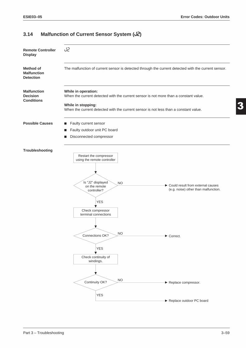
ESIE03–05 Error Codes: Outdoor Units
33
4
5
1
3.14 Malfunction of Current Sensor System (JJJJ2222)Remote Controller Display
J2
Method of Malfunction Detection
The malfunction of current sensor is detected through the current detected with the current sensor.
Malfunction Decision Conditions
While in operation:When the current detected with the current sensor is not more than a constant value.
While in stopping:When the current detected with the current sensor is not less than a constant value.
Possible Causes Faulty current sensor
Faulty outdoor unit PC board
Disconnected compressor
TroubleshootingRestart the compressor
using the remote controller
Is "J2" displayedon the remote
controller?
Connections OK?
NO
NO
YES
YES
Continuity OK?NO
YES
Could result from external causes(e.g. noise) other than malfunction.
Correct.
Replace compressor.
Replace outdoor PC board
Check compressorterminal connections
Check continuity ofwindings.
Part 3 – Troubleshooting 3–59

Error Codes: Outdoor Units ESIE03–05
3
1
3
4
5
Caution Be sure to turn off power switch before connect or disconnect connector, or parts damage may be occurred.
3–60 Part 3 – Troubleshooting

ESIE03–05 Error Codes: Outdoor Units
33
4
5
1
3.15 Failure of Capacity Setting (PPPPJJJJ)Remote Controller Display
PJ
Method of Malfunction Detection
Check whether set value (i.e., factory set value) written in E2PROM or set value with the (replaced) capacity setting adapter (X26A) is the same as that of outdoor unit capacity.
Malfunction Decision Conditions
When the set value with the E2PROM differs from that of the outdoor unit capacity or any capacity setting adapter other than that suitable for the applicable PC board is installed. (However, the failure decision is made only when the power supply is turned on.)
Possible Causes Improper set value with E2PROM
Improper capacity setting adapter installed
Faulty outdoor unit PC board
Troubleshooting
Caution Be sure to turn off power switch before connect or disconnect connector, or parts damage may be occurred.
Notes The capacity setting adapter is not connected at the time of shipment from factory. (The capacity
is written in the E2PROM.) This capacity setting adapter is required only when the PC board is replaced with a spare PC board.
Refer to instructions on how to set Sky-Air L- series Spare Part outdoor PC board on page 4-20.
Is thecapacity settingadapter (X26A)
connected to the outdoorunit PC board?
[See (Note)below.]
NO
YES
Connect an adapter suitablefor the applicable model.
NOCorrect the combination if wrong.
Check whether thecombination of the
capacity setting adapter(X26A) installed is correct
for the PC board.
Part 3 – Troubleshooting 3–61

Error Codes: Outdoor Units ESIE03–05
3
1
3
4
5
3–62 Part 3 – Troubleshooting

ESIE03–05 Error Codes: System Malfunctions
1
Part 333
4
5
4 Error Codes: System Malfunctions
4.1 What Is in This Chapter?
Introduction In the first stage of the troubleshooting sequence, it is important to correctly interpret the error code on the remote controller display. The error code helps you to find the cause of the problem.
Overview This chapter contains the following topics:
Topic See page
4.2–Gas Shortage Detection (U0) 3–64
4.3–Reverse Phase (U1) 3–65
4.4–Transmission Error between Indoor and Outdoor Unit (U4 or UF) 3–67
4.5–Transmission Error between Indoor Unit and Remote Controller (U5) 3–69
4.6–Transmission Error between MAIN Remote Controller and SUB Remote Controller (U8)
3–70
4.7–Malfunctioning Field Setting Switch (UA) 3–71
Part 3 – Troubleshooting 3–63

Error Codes: System Malfunctions ESIE03–05
3
1
3
4
5
4.2 Gas Shortage Detection (UUUU0000)
Error code U0
Error method The discharge pipe thermistor detects the malfunction temperature at which there can be a gas shortage. If the discharge temperature exceeds 125˚C during more than 20 s, the outdoor unit will stop and retry when the guard timer is OFF (3 min have passed).
During the retrial, the expansion valve will be opened 70 pulses more (cool) or 80 pulses more (heat) than in case of the previous start. When the unit restarts with a fully opened expansion valve, the remote controller displays “U0” after pressing the test button.
Error generation The error is generated when the microcomputer detects gas shortage. However, the unit can still operate.
Causes The possible causes are:
Refrigerant shortage
Clogging of the refrigerant piping circuit.
Troubleshooting To troubleshoot, proceed as follows:
Caution Be sure to turn off power switch before connect or disconnect connector, or parts damage may be occurred.
Check the amount ofrefrigerant.
NoIs it correct?Fill with the proper
amount of refrigerant.
Check the refrigerant pipingcircuit for clogging.Check the expansion valve.Refer to error E9.Check the discharge thermistor.Refer to error F3.
Yes
3–64 Part 3 – Troubleshooting

ESIE03–05 Error Codes: System Malfunctions
33
4
5
1
4.3 Reverse Phase (UUUU1111)Error code U1
This error code is only for 3-phase equipment.
Error generation The error is generated when the difference between phase L1 and L3 is not 240˚. The illustration below shows the 3-phase network.
Causes The possible causes are:
Malfunctioning power supply wiring connection
Broken or disconnected power supply wiring
Malfunctioning outdoor unit PCB
12090 180
L1 L2 L3
240
240˚
270 360
L1
L3 L2
240˚
120˚
Part 3 – Troubleshooting 3–65

Error Codes: System Malfunctions ESIE03–05
3
1
3
4
5
Troubleshooting To troubleshoot, proceed as follows:
Caution Be sure to turn off power switch before connect or disconnect connector, or parts damage may be occurred.
Check power
Is U1displayed on the
remote controller?Phases are not
correct.
Replace outdoorunit PCB.
No
Yes
L1-L2-L3= 400V –10%L1-N= 230V –10%L2-N= 230V –10%L3-N= 230V –10%
Does the powercorrespond withprevious data?
Correct powersupply.
1. Turn the power off.2. Change L1-L2 or L2-L3.3. Turn the power on.
No
Yes
3–66 Part 3 – Troubleshooting

ESIE03–05 Error Codes: System Malfunctions
33
4
5
1
4.4 Transmission Error between Indoor and Outdoor Unit (UUUU4444 or UUUUFFFF)Error code U4 or UF
Error generation The error is generated when the microprocessor detects that the transmission between the indoor and the outdoor unit is not normal over a certain amount of time.
Causes The possible causes are:
Wiring indoor-outdoor transmission wire is incorrect
Malfunctioning indoor unit PCB
Malfunctioning outdoor unit PCB
Outside cause (noise...).
Troubleshooting 1 Diagnosis of incorrect or broken/disconnected wiring. If the LEDs on the indoor unit PC board are off, it indicates that the transmission wiring between indoor and outdoor units may be incorrect or broken/disconnected.:
Caution Be sure to turn off power switch before connect or disconnect connector, or parts damage may be occurred.
Does outdoor unit
microcomputernormal H1P
flash?
Isindoor-outdoor
transmission wire connectedcorrectly?
Is H1P flashing?
NO YES
NO
NO
NO
NO (ON or OFF)
NO (OFF)
YES
YES
YES
Is HAP flashing?
Is HBP flashing?
To outdoor unit(next page)
Is H2P on?
Check ofindoor unitmicrocom-puter normalHAP
Check ofindoor unittransmissionmalfunctionHBP
YES
YES
Turn the power supply off once and then back on.
Failure of indoor unit PCB or malfunction of power supply system.
Resets normally.Could be outsidecause (noise...).
Failure of indoor unit PCB.
Wire correctly.
Part 3 – Troubleshooting 3–67

Error Codes: System Malfunctions ESIE03–05
3
1
3
4
5
Troubleshooting 2 To troubleshoot, proceed as follows:
Caution Be sure to turn off power switch before connect or disconnect connector, or parts damage may be occurred.
Turn off the powersupply, disconnect the NO.2 indoor-outdoor transmission wire, and turn power supply back on.
Is HAP flashing?
YES
YES
NO (ON or OFF)
NO (OFF)
NO
Is HAP flashing?YES
NO
Is HAP flashing?
Continued fromprevious page
Is HAP on?
Check ofoutdoor unitmicrocom-puter normalHAP
YES Turn the power supply off once and then back on.
Failure of indoor unit PCB.
Failure of outdoor unit PCB or malfunction of power supply system.
Indoor PCB malfunction.
Resets normally.Could be outside cause (noise...).
Failure of outdoor unit PCB.
Resets normally.Could be outside cause(noise...).
"U4" displaysconstantly?
YES
NO
3–68 Part 3 – Troubleshooting

ESIE03–05 Error Codes: System Malfunctions
33
4
5
1
4.5 Transmission Error between Indoor Unit and Remote Controller (UUUU5555)Error code U5
Error generation The error is generated when the microprocessor detects that the transmission between the indoor unit and the remote controller is not normal over a certain amount of time.
Causes The possible causes are:
Malfunctioning remote controller
Malfunctioning indoor PCB
Outside cause (noise...)
Connection of two master remote controllers (when using two remote controllers).
Troubleshooting To troubleshoot, proceed as follows:
Caution Be sure to turn off power switch before connect or disconnect connector, or parts damage may be occurred.
Set one of the remote controllers to SUB, turn off the power supply temporarily, then restart operation.
Indoor unit PCB replacement.
Malfunction could be produced by noise. Check the surrounding area and restart operation. Change todouble-core independent cable.
Failure of remote controller PCB or replacement of defective indoor unit PCB.
All indoorunit PCB
microcomputernormal monitors
flashing
Usingmulticore
transmission wiringbetween indoor unit
and remotecontroller
Control by 2 remotecontrollers
NO
YES
YES
YES
YES
Resetsnormally when
power supply is turnedoff temporarily.
NO
SS1 of bothremote controllers is
set to MAIN.
YES
NO NO
Part 3 – Troubleshooting 3–69

Error Codes: System Malfunctions ESIE03–05
3
1
3
4
5
4.6 Transmission Error between MAIN Remote Controller and SUB Remote Controller (UUUU8888)
Error code U8
Error generation The error is generated when, in case of controlling with two remote controllers, the microprocessor detects that the transmission between the indoor unit and the remote controllers (MAIN and SUB) is not normal over a certain amount of time.
Causes The possible causes are:
Transmission error between MAIN remote controller and SUB remote controller
Connection among SUB remote controllers
Malfunctioning remote controller PCB.
Troubleshooting To troubleshoot, proceed as follows:
Caution Be sure to turn off power switch before connect or disconnect connector, or parts damage may be occurred.
Turn the SS-1 switch of one remote controller to MAIN.Turn OFF the power supply,and restart operation.
Turn OFF the power once and restart operation.Replace remote controller PCB if any error is generated.
Turn the SS-1switch of one remote controller to MAIN.Turn OFF the power supply, and restart operation.
Controllingwith 2-remote
controller
Both SS-1switches on remote
controllers are turnedto SUB
SS-1 switchon remote controller
PCB is turnedto MAIN
NONO
NO
YES
YES
YES
3–70 Part 3 – Troubleshooting

ESIE03–05 Error Codes: System Malfunctions
33
4
5
1
4.7 Malfunctioning Field Setting Switch (UUUUAAAA)Error code UA
Error generation The error is generated when incorrect field settings have been set for pair/twin/triple/double twin.
Causes The possible causes are:
Malfunctioning indoor or outdoor unit PCB
Malfunctioning power supply PCB
Indoor-outdoor, indoor-indoor unit transmission wiring
Malfunctioning remote controller wiring.
Part 3 – Troubleshooting 3–71

Error Codes: System Malfunctions ESIE03–05
3
1
3
4
5
Troubleshooting To troubleshoot, proceed as follows:
Caution Be sure to turn off power switch before connect or disconnect connector, or parts damage may be occurred.
Is there220-240 VAC
between No.1 andNo.3 of X2M(indoor Unit)?
Is thepower supplyPCB correctlyconnected?
YES
YESYES
Is theindoor-indoor
and indoor-outdoorjumper correctly
connected?
Is theindoor-indoor
and indoor-outdoorjumper correctly
connected?
NO
NO
NO
NO
Isthe outdoor unitused for Twin
system?
Isthe remote
controller connectedto more thanone indoor
unit?
NO
YES
Are themicrocomputernormal montiors
(HAP) of all indoor unitPCB
flashing?
YES
Are thetransmission
normal montiors(HBP) of all indoor unit
PCBflashing?
NO
Is thesetting of
Pair/Twin/Triple set
correctly?
YES
NO
YES
NO
YES
Operating normally?
YES
YES
NO
NO
Turn the power off once, then back on, and restart operation.
Connect the remote controller correctly.
Check setting "No. of Connected Twin System Indoor Units" of indoor unit.
Set correctly.
Connect correctly.
Connect correctly.
Replace the transformer.
Wiring could be incorrect, recheck.
Connect correctly.
Indoor unit PCB replacement.
Operates normally.
3–72 Part 3 – Troubleshooting

ESIE03–05 Additional Checks for Troubleshooting
1
Part 333
4
5
5 Additional Checks for Troubleshooting
5.1 What Is in This Chapter?
Introduction This chapter explains how you must check the units to carry out troubleshooting correctly.
Overview This chapter contains the following topics:
Topic See page
5.2–Indoor Unit: Checking the Fan Motor Hall IC 3–74
5.3–Indoor Unit: Checking the Power Supply Wave Form 3–75
5.4–Outdoor Unit: Checking the Refrigerant System 3–76
5.5–Outdoor unit: Checking the Installation Condition 3–77
5.6–Outdoor Unit: Checking the Discharge Pressure 3–78
5.7–Outdoor Unit: Checking the Expansion Valve 3–79
5.8–Checking the Thermistors 3–80
5.9–R1T and R2T: Resistance Conversion Table (Ambient & Coil Sensor) 3–81
5.10–R3T: Resistance Conversion Table (Discharge Pipe Sensor) 3–82
5.11–Evaluation of abnormal high pressure 3–83
5.12–Evaluation of abnormal low pressure 3–84
5.13–Check for Clogged Points 3–85
Part 3 – Troubleshooting 3–73

Additional Checks for Troubleshooting ESIE03–05
3
1
3
4
5
5.2 Indoor Unit: Checking the Fan Motor Hall IC
Applicable units Units using phase cut controlled fan motor with feedback signal.
Checking To check the indoor unit fan motor hall IC, proceed as follows:
Step Action
1 Make sure connector S7 on PCB 1 is properly connected.
2 Make sure the power is ON and that there is no operation.
3 Measure the voltage between pin 1 and 3 of S7.
4 Turn the fan one rotation with your hand and measure the generated pulses.
5 Proceed as follows:
If... Then...
The measured voltage between pin 1 and 3 does not equal 5 V
Replace the PCB 1.
The generated pulses do not equal 3 pulses between pin 2 and 3
Replace the fan motor.
The measured voltage does not equal 5 V and the generated pulses do not equal 3 pulses between pin 2 and 3
Replace the PCB 1.
3–74 Part 3 – Troubleshooting

ESIE03–05 Additional Checks for Troubleshooting
33
4
5
1
5.3 Indoor Unit: Checking the Power Supply Wave FormChecking To check the power supply wave form, proceed as follows:
Step Action
1 Measure the power supply wave form between pin 1 and 3 of X1M for the outdoor units or between pin 1 and 3 of X2M for the indoor units.
2 Check whether the power supply wave form is a sine wave:
3 Check whether there is wave form disturbance near the zero cross:
4 Adjust the supply voltage.
Part 3 – Troubleshooting 3–75

Additional Checks for Troubleshooting ESIE03–05
3
1
3
4
5
5.4 Outdoor Unit: Checking the Refrigerant System
Checking To check the refrigerant system, proceed as follows:
Check discharge pipethermistor R3T.
Is thedischarge pipethermistor R3T
disconnected from theholder?
Check for gas leaksusing a leak tester.
Yes
No
Replace therefrigerant.
Correct theproblem.
3–76 Part 3 – Troubleshooting

ESIE03–05 Additional Checks for Troubleshooting
33
4
5
1
5.5 Outdoor unit: Checking the Installation ConditionChecking To check the installation condition, proceed as follows:
Check the space for all airpassage around the suction and
discharge areas.
Change the installationlocation.
Does thedischarged air from otheroutdoor units cause anincrease of the suction
temperature?
Isthe heat
exchangerclean?
Is theminimum space
respected?
Is there enoughair flow?
Clean the heatexchanger.
Change theinstallationlocation ordirection.
Check the outdoor ambienttemperature R1T. This temperature
must be lower than 43 C.
No
Yes
No
Yes
No
Yes
Change the installationlocation.
Yes
Part 3 – Troubleshooting 3–77
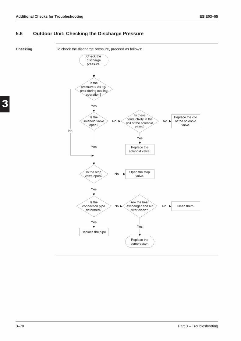
Additional Checks for Troubleshooting ESIE03–05
3
1
3
4
5
5.6 Outdoor Unit: Checking the Discharge Pressure
Checking To check the discharge pressure, proceed as follows:
Check thedischargepressure.
Is thepressure > 24 kg/cm≤ during cooling
operation?
Is thesolenoid valve
open?
Is the stopvalve open?
Is theconnection pipe
deformed?
Are the heatexchanger and air
filter clean?
Replace thecompressor.
Clean them.
Replace the pipe
Yes
Yes
No
Is thereconductivity in thecoil of the solenoid
valve?
NoReplace the coilof the solenoid
valve.No
Replace thesolenoid valve.
Yes
Yes
No No
YesYes
Open the stopvalve.
No
3–78 Part 3 – Troubleshooting

ESIE03–05 Additional Checks for Troubleshooting
33
4
5
1
5.7 Outdoor Unit: Checking the Expansion ValveChecking To check the electronic expansion valve, proceed as follows:
Step Action
1 Check if the expansion valve connector is correctly inserted in the X24A of PCB 1.
2 Compare the expansion valve unit with the number of the connector to make sure it is cor-rectly connected.
3 Switch the power OFF.
4 Switch the power ON to check whether the expansion valve is producing a clicking sound.
5 Check the coil current: Open circuit < normal < short circuit
6 Check the clicking sound again.
If... Then...
The expansion valve has no clicking sound
Disconnect the valve connector without the clicking sound and proceed to step 5.
The table below contains the reference resistance values.
— Grey Black Yellow Red Orange
Grey — 40-50 Ω 40-50 Ω 40-50 Ω 40-50 Ω
Black 40-50 Ω — 80-100 Ω 80-100 Ω 80-100 Ω
Yellow 40-50 Ω 80-100 Ω — 80-100 Ω 80-100 Ω
Red 40-50 Ω 80-100 Ω 80-100 Ω — 80-100 Ω
Orange 40-50 Ω 80-100 Ω 80-100 Ω 80-100 Ω —
If... Then...
There is a clicking sound The expansion valve works properly.
There is no clicking sound Replace the expansion valve unit.
There is still no clicking sound Replace outdoor PCB 1.
Part 3 – Troubleshooting 3–79
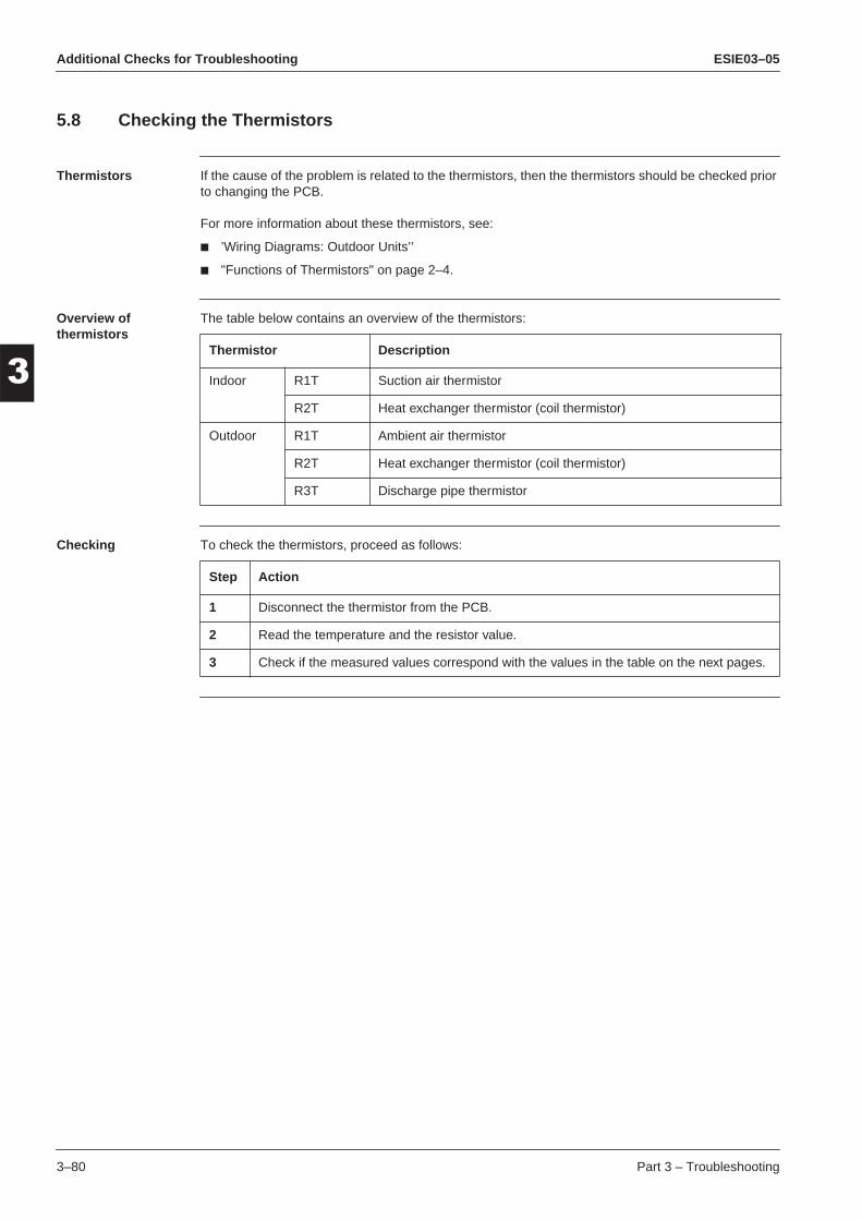
Additional Checks for Troubleshooting ESIE03–05
3
1
3
4
5
5.8 Checking the Thermistors
Thermistors If the cause of the problem is related to the thermistors, then the thermistors should be checked prior to changing the PCB.
For more information about these thermistors, see:
’Wiring Diagrams: Outdoor Units’’
"Functions of Thermistors" on page 2–4.
Overview of thermistors
The table below contains an overview of the thermistors:
Checking To check the thermistors, proceed as follows:
Thermistor Description
Indoor R1T Suction air thermistor
R2T Heat exchanger thermistor (coil thermistor)
Outdoor R1T Ambient air thermistor
R2T Heat exchanger thermistor (coil thermistor)
R3T Discharge pipe thermistor
Step Action
1 Disconnect the thermistor from the PCB.
2 Read the temperature and the resistor value.
3 Check if the measured values correspond with the values in the table on the next pages.
3–80 Part 3 – Troubleshooting

ESIE03–05 Additional Checks for Troubleshooting
33
4
5
1
5.9 R1T and R2T: Resistance Conversion Table (Ambient & Coil Sensor)Temperature – resistance
The table below is the thermistor (R1T and R2T) temperature – resistance conversion table.
Temp. (˚C)
R1T (kΩ)
R2T (kΩ)
Temp. (˚C)
R1T (kΩ)
R2T (kΩ)
Temp. (˚C)
R1T (kΩ)
R2T (kΩ)
-20 197.81 192.08 20 25.01 24.45 60 4.96 4.87
-19-18-17-16-15-14-13-12-11
186.53175.97166.07156.80148.10139.94132.28125.09118.34
181.16170.94161.36152.38143.96136.05128.63121.66115.12
212223242526272829
23.9122.8521.8520.9020.0019.1418.3217.5416.80
23.3722.3521.3720.4519.5618.7317.9317.1716.45
616263646566676869
4.794.624.464.304.164.013.883.753.62
4.704.544.384.234.083.943.813.683.56
-10 111.99 108.96 30 16.10 15.76 70 3.50 3.44
-9-8-7-6-5-4-3-2-1
106.03100.41
95.1490.1785.4981.0876.9373.0169.32
103.1897.7392.6187.7983.2578.9774.9471.1467.56
313233343536373839
15.4314.7914.1813.5913.0412.5112.0111.5211.06
15.1014.4813.8813.3112.7712.2511.7611.2910.84
717273747576777879
3.383.273.163.062.962.862.772.682.60
3.323.213.113.012.912.822.722.642.55
0 65.84 64.17 40 10.63 10.41 80 2.51 2.47
123456789
62.5459.4356.4953.7151.0948.6146.2644.0541.95
60.9657.9455.0852.3849.8347.4245.1442.9840.94
414243444546474849
10.219.819.429.068.718.378.057.757.46
10.009.619.248.888.548.217.907.607.31
—10 39.96 39.01 50 7.18 7.04
111213141516171819
38.0836.3034.6233.0231.5030.0628.7027.4126.18
37.1835.4533.8132.2530.7729.3728.0526.7825.59
515253545556575859
6.916.656.416.656.416.185.955.745.14
6.786.536.536.536.296.065.845.435.05
Part 3 – Troubleshooting 3–81

Additional Checks for Troubleshooting ESIE03–05
3
1
3
4
5
5.10 R3T: Resistance Conversion Table (Discharge Pipe Sensor)
Temperature – resistance
The table below is the thermistor (R3T) temperature – resistance conversion table.
Temp. (˚C)
Resist. (kΩ)
Temp. (˚C)
Resist. (kΩ)
Temp. (˚C)
Resist. (kΩ)
— — 60.0 52.8 130.0 5.4
—-6.0-4.0-2.0
—1120.01002.5898.6
62.064.066.068.0
48.945.342.039.0
132.0134.0136.0138.0
5.44.84.64.3
0.0 806.5 70.0 36.3 140.0 4.1
2.04.06.08.0
724.8652.2587.6530.1
72.074.076.078.0
33.731.429.227.2
142.0144.0146.0148.0
3.93.73.53.3
10.0 478.8 80.0 25.4 150.0 3.2
12.014.016.018.0
432.9392.0355.3322.4
82.0———
23.7———
152.0154.0156.0158.0
3.02.92.72.6
20.0 292.9 — — 160.0 2.5
22.024.026.028.0
266.3242.5221.0201.6
92.094.096.098.0
16.915.814.813.9
162.0164.0166.0168.0
2.32.52.12.0
30.0 184.1 100.0 13.1 170.0 1.9
32.034.036.038.0
168.3154.0141.0129.3
102.0104.0106.0108.0
12.311.510.810.2
172.0174.0176.0178.0
1.91.81.71.6
40.0 118.7 110.0 9.6 180.0 1.5
42.044.046.048.0
109.0100.292.284.9
112.0114.0116.0118.0
9.08.58.07.6
—50.0 78.3 120.0 7.1
52.054.056.048.0
72.266.761.657.0
122.0124.0126.0128.0
6.76.46.05.7
3–82 Part 3 – Troubleshooting

ESIE03–05 Additional Checks for Troubleshooting
33
4
5
1
5.11 Evaluation of abnormal high pressureAbnormally high pressure level is mostly caused by the condenser side. The following contents are provided by service engineer based on their field checks. Further, the number is listed in the order of degree of influence.
In cooling operation
In heating operation
Check items (Possible causes) Judgment
Does the outdoor unit fan run normally? Visual inspection
Is the outdoor unit heat exchanger clogged? Visual inspection
Is there clogging before or after the EV (capil-lary)?
Check if there is a temperature difference before and after EV (capillary).Check if the main valve unit of EV operates (by noise, vibration).
Is the check valve clogged?*Heat pump model only
Check if there is a temperature difference before and after check valve.--> If YES, the check valve is caught.
Is the HPS normal? Check continuity by using a tester.
Is the outdoor unit installed under such condi-tions that short circuit easily occurs?
Visual inspection
Is the piping length 5 meters or less? Visual inspection
Does air enter the refrigerant system? Conduct refrigerant collection and vacuum dry-ing, and then add proper amount refrigerant.
Is the refrigerant overcharged? Conduct refrigerant collection and vacuum dry-ing, and then add proper amount refrigerant.
Check items (Possible causes) Judgment
Does the indoor unit fan run normally? Visual inspection
Is the indoor unit heat exchanger clogged? Visual inspection
Is the indoor unit installed under such conditions that short circuit easily occurs?
Visual inspection
Is there clogging before or after the EV (capil-lary)?
Check if there is a temperature difference before and after EV (capillary).Check if the main valve unit of EV operates (by noise, vibration).
Is the check valve clogged? Check if there is a temperature difference before and after check valve.--> If YES, the check valve is caught.
Is the HPS normal? Check continuity using a tester.
Is the piping length 5 meters or less? Visual inspection
Does air enter the refrigerant system? Conduct refrigerant collection and vacuum dry-ing, and then add proper amount refrigerant.
Is the refrigerant overcharged? Conduct refrigerant collection and vacuum dry-ing, and then add proper amount refrigerant.
Part 3 – Troubleshooting 3–83

Additional Checks for Troubleshooting ESIE03–05
3
1
3
4
5
5.12 Evaluation of abnormal low pressure
Abnormally low pressure level is mostly caused by the evaporator side. The following contents are provided based on field checking of service engineer. Further, the number is listed in the order of degree of influence.
In cooling operation
In heating operation
Check items (Possible causes) Judgment
Does the outdoor unit fan run normally? Visual inspection
Is the indoor unit filter clogged? Visual inspection
Is there clogging before or after the EV (capil-lary)?
Check if there is a temperature difference before and after EV (capillary).Check if the main valve unit of EV operates (by noise, vibration).
Is the check valve clogged?*Heat pump model only
Check if there is a temperature difference before and after check valve.-> If YES, the check valve is caught.
Is the LPS normal? Check continuity using a tester.
Is the indoor unit installed under such conditions that short circuit easily occurs?
Visual inspection
Is the refrigerant gas short? Conduct refrigerant collection and vacuum dry-ing, and then add proper amount refrigerant.
Check items (Possible causes) Judgment
Does the outdoor unit fan run normally? Visual inspection
Is the outdoor unit heat exchanger clogged? Visual inspection
Is the outdoor unit installed under such condi-tions that short circuit easily occurs?
Visual inspection
Is there clogging before or after the EV (capil-lary)?
Check if there is a temperature difference before and after EV (capillary).Check if the main valve unit of EV operates (by noise, vibration).
Is the check valve clogged? Check if there is a temperature difference before and after check valve.--> If YES, the check valve is caught.
Is the LPS normal? Check continuity using a tester.
Is the refrigerant gas short? Conduct refrigerant collection and vacuum dry-ing, and then add proper amount refrigerant.
3–84 Part 3 – Troubleshooting

ESIE03–05 Additional Checks for Troubleshooting
33
4
5
1
5.13 Check for Clogged PointsChecks Temperature differences must occur before or after the clogged points!
Check points Check factor Causes Remedies
1 Around expansion mechanism
Temperature difference
Dust
Choked moisture
Reduced effective pipe diameter due to adherent contamination, etc.
Replace the expan-sion valve.
2 Accumulator Frosting Choked moisture Blow a nitrogen gas, and then replace the refrigerant.
3 Distributor Temperature difference
Dust
Choked moisture
Reduced effective pipe diameter due to adherent contamination, etc.
Replace the heat exchanger or distributor.
4 Field piping Temperature difference
Collapsed pipe Replace the pipe.
5 Stop valve Temperature difference
The stop valve is not fully open.
Open the stop valve fully.
RAC
Indoor Unit Outdoor Unit
COMP
1
2
33
4 5
Part 3 – Troubleshooting 3–85

Additional Checks for Troubleshooting ESIE03–05
3
1
3
4
5
3–86 Part 3 – Troubleshooting

ESIE03–05
4
3
4
5
4
Part 4Commissioning and Test
Run
What is in this part? This part contains the following chapters:
Chapter See page
1–Pre-Test Run Checks 4–3
2–Field settings 4–9
3–Test Run and Operation Data 4–33
Part 4 – Commissioning and Test Run 4–1

ESIE03–05
3
1
4
5
4–2 Part 4 – Commissioning and Test Run

ESIE03–05 Pre-Test Run Checks
1
Part 43
4
5
1 Pre-Test Run Checks
1.1 What Is in This Chapter?
Introduction This chapter contains the following information:
Checks before test run
Test run checks
Setting the address for the receiver of the wireless remote controller
Setting the address for the wireless remote controller.
Overview This chapter contains the following topics:
Topic See page
1.2–Test Run Checks 4–4
1.3–Setting the Wireless Remote Controller 4–5
Part 4 – Commissioning and Test Run 4–3
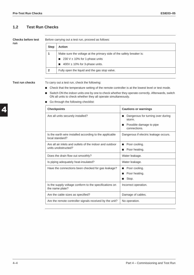
Pre-Test Run Checks ESIE03–05
3
1
4
5
1.2 Test Run Checks
Checks before test run
Before carrying out a test run, proceed as follows:
Test run checks To carry out a test run, check the following:
Check that the temperature setting of the remote controller is at the lowest level or test mode.
Switch ON the indoor units one by one to check whether they operate correctly. Afterwards, switch ON all units to check whether they all operate simultaneously.
Go through the following checklist:
Step Action
1 Make sure the voltage at the primary side of the safety breaker is:
230 V ± 10% for 1-phase units
400V ± 10% for 3-phase units.
2 Fully open the liquid and the gas stop valve.
Checkpoints Cautions or warnings
Are all units securely installed? Dangerous for turning over during storm.
Possible damage to pipe connections.
Is the earth wire installed according to the applicable local standard?
Dangerous if electric leakage occurs.
Are all air inlets and outlets of the indoor and outdoor units unobstructed?
Poor cooling.
Poor heating.
Does the drain flow out smoothly? Water leakage.
Is piping adequately heat-insulated? Water leakage.
Have the connections been checked for gas leakage? Poor cooling.
Poor heating.
Stop.
Is the supply voltage conform to the specifications on the name plate?
Incorrect operation.
Are the cable sizes as specified? Damage of cables.
Are the remote controller signals received by the unit? No operation.
4–4 Part 4 – Commissioning and Test Run

ESIE03–05 Pre-Test Run Checks
3
4
5
1
1.3 Setting the Wireless Remote ControllerIntroduction To set the wireless remote controller, you have to set the address for:
The receiver of the wireless remote controller
The wireless remote controller.
Setting the address for the receiver
The address for the receiver of the wireless remote controller is factory set to 1. To change this setting, proceed as follows:
Step Action
1 Turn OFF the power.
2 Remove the sealing pad on the top of the receiver.
3 Set the wireless address switch (SS2) according to the table below. You can find the wire-less address switch attached on the PCB of the receiver and it is visible through the small opening on the back of the receiver.
4 If you use a wired and a wireless remote controller for one indoor unit, proceed as follows:
1. Set the wired remote controller to MAIN: On the remote controller.2. Set the wireless remote controller to SUB: On the receiver with the MAIN/SUB switch
(SS1).
5 Seal off the opening of the address switch and the MAIN/SUB switch with the attached sealing pad.
6 Make sure to also change the address on the remote controller.
12
3M
SS2
SS1
S
Sealing pad
Small opening
Receiver
12
12
12
3 3 3
Unit No.
SS2
No. No. No.
S
M
S
M
SS1
MAIN SUBMAIN/SUB
12
3M
SS2
SS1
S
Sealing pad
Small opening
Receiver
Part 4 – Commissioning and Test Run 4–5

Pre-Test Run Checks ESIE03–05
3
1
4
5
Setting the address for the wireless remote controller
The address for the wireless remote controller is factory set to 1. To change this setting, proceed as follows:
Step Action
1 Hold down the FILTER RESET button and the TEST button for at least 4 s, to go to field set mode. The display indicates the field set mode.
2 Press the FAN button to select a multiple setting (A/b), see ‘Multiple settings A/b’ further in this section. Each time you press the button, the display switches between “A” and “b”.
FILTER RESET
TEST
FAN
4–6 Part 4 – Commissioning and Test Run

ESIE03–05 Pre-Test Run Checks
3
4
5
1
3 Press the UP and DOWN buttons to set the address. Set the same address as thereceiver (1, 2 or 3). The receiver does not work with addresses 4, 5 and 6.
4 Press the RESERVE button to confirm the setting.
Step Action
UPDOWN
RESERVE
Part 4 – Commissioning and Test Run 4–7

Pre-Test Run Checks ESIE03–05
3
1
4
5
Multiple settings A/bWhen an outside control (central remote controller...) controls an indoor unit, sometimes the indoor unit does not respond to ON/OFF and temperature settings commands from this controller.
5 Press the TEST button to quit the field set mode and return to the normal display.
Step Action
UP
FAN
RESERVE CANCEL
TIMER
DOWN
TEMPTIME
ON / OFF
MODE
SWING
/TEST
˚C
TEST
Remote controller Indoor unit
SettingRemote controller display
Control of other air condi-tioners and units
No other control
A: Standard All items are displayed. Commands other than ON/OFF and temperature setting accepted. (1 long beep or 3 short beeps emitted)
b: Multi Sys-tem
Only one item is dis-played. This item is only shown for a few seconds.
All commands accepted (2 short beeps)
4–8 Part 4 – Commissioning and Test Run

ESIE03–05 Field settings
1
Part 43
4
5
2 Field settings
2.1 What Is in This Chapter?
Introduction This chapter contains the following information:
How to change the field settings
The field settings
The factory settings.
Overview This chapter contains the following topics:
Topic See page
2.2–How to Change the Field Settings with the Wired Remote Controller 4–10
2.3–How to Change the Field Settings with the Wireless Remote Controller 4–12
2.4–Overview of the Field Settings of the Indoor Units 4–13
2.5–Overview of the Factory Settings of the Indoor Units 4–14
2.6–Setting the Ceiling Height 4–15
2.7–Setting the Filter Counter 4–16
2.8–MAIN/SUB Setting when Using Two Remote Controllers 4–17
2.9–Setting the Centralized Group No. 4–18
2.10–Field settings when using a spare part PCB of Sky-Air L-series outdoor unit 4–20
2.11–The Field Setting Levels 4–23
2.12–Overview of the Field Settings: RYEP71-125L 4–26
2.13–Jumpers 4–28
2.14–DIP switch DS1 4–29
2.15–DIP switch DS2 4–30
Part 4 – Commissioning and Test Run 4–9

Field settings ESIE03–05
3
1
4
5
2.2 How to Change the Field Settings with the Wired Remote Controller
Installation conditions
The field settings have to be changed with the remote controller according to the installation conditions.
Wired remote controller
The illustration below shows the wired remote controller.
Components The table below contains the components of the wired remote controller.
1293
25
22
11
10
37
35
27
26
1214
17
34
24520 211816 13 15 19
323130
29
28
4
36
33
823 76
No. Component No. Component
1 ON/OFF button 20 Air flow direction icon2 Operation lamp 21 Not available3 Operation mode icon 22 Fan speed icon4 Ventilation mode icon 23 Defrost/hotstart mode icon5 Ventilation icon 24 Air filter cleaning time icon6 Air cleaning icon 25 Element cleaning time icon7 Leave home icon 26 Ventilation mode button8 External control icon 27 Ventilation amount button9 Change-over under centralised control icon 28 Inspection/test operation button10 Day of the week indicator 29 Programming button11 Clock display 30 Schedule timer button12 Maximum set temperature 31 Time adjust button13 Minimum set temperature 32 Temperature adjust buttons14 Schedule timer icon 33 Operation change/ button15 Action icons 34 Setpoint/limit button16 Off icon 35 Fan speed button17 Inspection required 36 Air flow direction adjust button18 Set temperature display 37 Air filter cleaning time icon reset19 Setting
4–10 Part 4 – Commissioning and Test Run

ESIE03–05 Field settings
3
4
5
1
Setting To set the field settings, you have to change:“Mode No.”
“First code No.”
“Second code No.”.
To change the field settings, proceed as follows:
Step Action
1 Hold down the INSPECTION/TEST button for at least 4 s during normal mode to enter the “Field setting mode”.
2 Press the TEMPERATURE CONTROL button until the desired “Mode No.” appears.
3 If the indoor unit is under group control, all settings for all the indoor units are set at the same time. Use the codes 10 to 15 to apply this group control and proceed to the next step.
If you want to set the indoor units of one group individually or if you want to read out the last settings, use the codes 20 to 25 which are displayed in brackets. Press the TIMER SELECTION button to select the “Indoor unit No.” for which you want to adjust the field settings.
4 Press the upper part of the PROGRAMMING TIME button to select the “First code No.”.
5 Press the lower part of the PROGRAMMING TIME button to select the “Second code No”.
6 Press the CONFIRMATION button to confirm the changed setting.
7 Press the INSPECTION/TEST button to return to “Normal mode”.
Part 4 – Commissioning and Test Run 4–11

Field settings ESIE03–05
3
1
4
5
2.3 How to Change the Field Settings with the Wireless Remote Controller
Optional accessories
If optional accessories are mounted on the indoor unit, the indoor unit setting may have to be changed.
Refer to OH98-2 or the installation manual (optional handbook) for each optional accessory.
Wireless remote controller
The illustration below shows the wireless remote controller.
Setting To set the field settings, you have to change:
“Mode No.”
“First code No.”
“Second code No.”.
To change the field settings, proceed as follows:
RESERVE button
INSPECTION/TEST button
Mode No.
Field setting mode
UP button
DOWN button
First code No.
Second code No.
MODE button
Step Action
1 Hold down the INSPECTION/TEST button for at least 4 s during normal mode to enter the “Field setting mode”.
2 Press the MODE button to select the desired “Mode No.”.
3 Press the UP button to select the “First code No.”.
4 Press the DOWN button to select the “Second code No.”
5 Press the RESERVE button to set the present settings.
6 Press the INSPECTION/TEST button to return to the “Normal mode”.
4–12 Part 4 – Commissioning and Test Run

ESIE03–05 Field settings
3
4
5
1
2.4 Overview of the Field Settings of the Indoor UnitsField settings The table below contains the possible field settings of all indoor units.
Mode No.
First code No.
Description of the settingSecond code No.
01 02 03 04
10 or 20 0 Filter counter Light contamination
heavycontamination
— —
1 Filter type Long Super long External Oil mist
2 Remote thermistor of the remote controller
TH1 = rem. controller
TH1 = air return
— —
3 Filter display Filter indic. No filter indic. — —
11 or 21 0 Number indoor to 1 outdoor Pair Twin Triple Double twin
1 Unified or indiv. set twin Group setting Indiv. setting — —
2 Fan OFF at thermostat OFF LL-speed OFF — —
12 or 22 0 KRP1B51/52/53 X1/X2 output Thermostat ON
Option Operation Malfunction
1 EKRORO Forced OFF ON/OFF oper-ation
— —
3 Fan speed heating thermostat OFF
LL-speed Set speed — —
5 Automatic restart Disabled Enabled — —
13 or 23 0 Ceiling height setting Normal High Extra high —
≤ 2.7 m >2.7≤3.0 m >3.0≤3.5 m —
1 Selection of air flow direction (setting for when a blocking pad kit has been inst alled).
4-way flow 3-way flow 2-way flow —
3 Horizontal discharge grill Enabled Disabled — —
4 Air flow direction adjust range setting
Draft preven-tion
Standard Ceil soil pre-vention
—
5 Field fan speed changeover air outlet
Standard Option 1 Option 2 —
6 External static pressure Normal High Low —
14 or 24 0 Additional timer to guard timer 0 s 5 s 10 s 15 s
1b
(Only in case of BRC1D52)
0 Permission level setting Level 2 Level 3 — —
1 Leave home function Not permitted
Permitted — —
2 Thermostat sensor in remote controller (for limit operation and leave home function only)
Use Not use — —
Part 4 – Commissioning and Test Run 4–13

Field settings ESIE03–05
3
1
4
5
2.5 Overview of the Factory Settings of the Indoor Units
Factory settings The table below contains the factory settings of all indoor units
Mode No.First code No.
Second code No.
FHYCP FHYKP FHYBP FAYP FDYP FUYP FHYP
10 or 20 0 01 01 01 01 01 01 01
1 01 — 01 — 02 01 —
2 02 02 02 — 02 02 02
3 01 01 01 01 01 01 01
11 or 21 0 01 01 01 01 01 01 01
1 01 01 01 01 01 01 01
2 01 01 01 01 01 01 01
12 or 22 0 01 01 01 01 01 01 01
3 01 — 01 — — — —
5 02 02 02 02 02 02 02
13 or 23 0 01 — — 01 — 01 01
1 01 — — — — — —
3 — 01 — — — — —
4 02 02 — — — — —
5 01 — — 01 — 01 01
6 — 01 01 — — — —
14 or 24 0 01 01 01 — 01 01 01
4–14 Part 4 – Commissioning and Test Run

ESIE03–05 Field settings
3
4
5
1
2.6 Setting the Ceiling HeightIncorrectly setting If you set the controller incorrectly, a connection mistake malfunction “UA” will appear on the remote controller display.
See ’Malfunctioning Field Setting Switch (UA)’ on page 3–71.
Mode No. 13 or 23 First code No. 0
Set the second code No., according to the tables below.
FHYP
FAYP
FHYCP and FUYP
Second code No. Ceiling-suspended type
01 Height < 2.7 m
02 2.7 m < height < 3.5 m
03 Not used
Second code No. Wall-mounted type
01 Normal
02 High
03 Extra high
Indoor unit Second code No. 4-way outlet 3-way outlet 2-way outlet
FHYCP35-71 01 < 2.7 m < 3.0 m < 3.5 m
02 < 3.0 m < 3.3 m < 3.8 m
03 < 3.5 m < 3.5 m —
FHYCP100-125 01 < 3.2 m < 3.6 m < 4.2 m
02 < 3.6 m < 4.0 m < 4.2 m
03 < 4.2 m < 4.2 m —
FUYP 01 < 2.7 m < 3.0 m < 3.5 m
02 < 3.0 m < 3.5 m < 3.8 m
03 < 3.5 m < 3.8 m —
Part 4 – Commissioning and Test Run 4–15

Field settings ESIE03–05
3
1
4
5
2.7 Setting the Filter Counter
Mode No. 10 or 20 First code No. 0
When the filter counter indication time is set to ON, set the second code No., according to the table below
Fan speed OFF when thermostat OFF
When the cool/heat thermostat is OFF, you can stop the indoor unit fan by switching the setting to “Fan OFF”. This setting is used as a countermeasure against odour, for example for barber shops and restaurants.
Fan speed changeover when thermostat OFF
You can switch the fan speed to the set fan speed when the heating thermostat is OFF. This setting is called “Set Fan Speed”.
Air flow direction setting
Set the air flow direction of the indoor units as given in the table below. This setting is needed when the optional air outlet blocking pad has been installed. The “Second code No” is factory set to “01”.
Unit Mode No. First code No. Second code No. Contamination
01 02
light heavy
FHYCP
10 or 20 0
±2500 hrs ±1250 hrs
FHYKP ±2500 hrs ±1250 hrs
FHYP ±2500 hrs ±1250 hrs
FUYP ±2500 hrs ±1250 hrs
FAYP~L ±200 hrs ±100 hrs
FAYP~B ±200 hrs ±100 hrs
FHYBP ±2500 hrs ±1250 hrs
FDYMP ±2500 hrs ±1250 hrs
FDYP ±2500 hrs ±1250 hrs
Mode No. First code No. Second code No. Setting
11 or 21 201 —
02 Fan OFF
Mode No. First code No. Second code No. Setting
12 or 22 301 LL fan speed
02 Set fan speed
Mode No First code No Second code No Setting
13 or 23 1
01 F: four-direction air flow
02 T: three-direction air flow
03 W: two direction air flow
4–16 Part 4 – Commissioning and Test Run

ESIE03–05 Field settings
3
4
5
1
2.8 MAIN/SUB Setting when Using Two Remote ControllersSituation The MAIN/SUB setting is necessary when one indoor unit is controlled by two remote controllers. When you use two remote controllers (control panel and separate remote controller), set one to MAIN and the other to SUB. You can do this by setting the switch on the remote controller’s PCB.
Setting The remote controllers are factory set to MAIN, so you only have to change one remote controller from MAIN to SUB. To change a remote controller from MAIN to SUB, proceed as follows:
Step Action
1 Insert a flathead screwdriver into the recess between the upper and lower part of the remote controller, as shown in the illustration below. Gently pry off the upper part of the controller, working from the two possible positions.
2 Turn the MAIN/SUB changeover switch on the PCB to “S”.
Upper part of the remote controller
Lower part of the remote controller
SM
SM
The switch is set to MAIN (factory setting)
Set the switch to SUB.
Part 4 – Commissioning and Test Run 4–17

Field settings ESIE03–05
3
1
4
5
2.9 Setting the Centralized Group No.
When? If you want to carry out centralized control with a central remote controller and a unified ON/OFF controller, you have to set the group No. for each group with the remote controller.
Wired remote controller
The illustration below shows the wired remote controller.
Setting To set the “Centralized group No.”, proceed as follows:
Individually address setting
If the address must be set individually for each unit, set the “Mode No.” to “30”. For example, for power consumption counting.
SETTING
UNIT No.
GROUP
3
1
4
56 2
7
Unit N˚
First Code N˚Second Code N˚
Mode N˚
Field set mode
Step Action
1 Switch ON the power supply of the central remote controller, the unified ON/OFF control-ler and the indoor unit(s).
2 Hold down the INSPECTION/TEST button for at least 4 s during normal mode to enter the “Field setting mode”.
3 Press the TEMPERATURE CONTROL button until “Mode No.” “00” appears.
4 Press the INSPECTION/TEST button to inspect the group No. display.
5 Set the “Group No.” for each group by pressing the PROGRAMMING TIME button.
The “Group No.” rises in the order of 1—00, 1—01, ..., 1—15, 2—00, ..., 2—15, 3—00, etc. The unified ON/OFF controller however displays only the range of group numbers selected by the switch for setting each address.
6 Press the CONFIRMATION button to enter the selected group No.
7 Press the INSPECTION/TEST button to return to normal mode.
4–18 Part 4 – Commissioning and Test Run

ESIE03–05 Field settings
3
4
5
1
Group control for FDYMP indoor unitsFor group control, cut the jumper indicated as “master/slave” on the PCB of the “slave” indoor units (=slave PCB). Do not cut the jumper on the PCB of the indoor unit to which the remote controller is connected (=master PCB).
Note It is not necessary to designate an indoor unit address when using group control. The address is automatically set when the power is activated.
Master Slave
Part 4 – Commissioning and Test Run 4–19

Field settings ESIE03–05
3
1
4
5
2.10 Field settings when using a spare part PCB of Sky-Air L-series outdoor unit
When In case the outdoor PCB needs to be replaced by a spare part PCB, it is required to execute below-mentioned field settings to ensure correct operation of the unit.
Required action In case of repair using this part, replace the part according to the following instruction:
Attention on service!1 Please be sure to work after turning off all related circuit breakers.2 Before starting the work, please touch the metal part of the product to discharge static electricity.3 Please exchange PCB ass’y when it is still included in the resin case.
(If it would be removed from the resin case, it can cause a PCB failure.)
- The parts for replacement : 1 The PCB ass’y- Accessories: 1 Capacity setting adaptor
2 The screw for terminal board : Two kinds (M4∞3 pieces, M5∞6 pieces)
Please replace the printed circuit board according to the following flow chart of “The flow to setup the printed circuit board ass’y”.
The flow to setup the printed circuit board ass’y:<Please check the capacity of the unit.>
Please attach the capacity setting adaptor (fig. 4) to CN26/X26A. (Refer to fig. 3 [Nr. 1])
<Is the capacity of the unit 71 or 100?>
<Is the capacity of the unit 125?>
Yes Yes
In the case of 71 or 100
Please remove and reuse the two following connectors from the original printed circuit board ass’y.
- Please attach the connector for terminal protection to CN14/X14A. (Refer to fig. 3 [Nr. 2])
- Please attach a short circuit connector to CN9/X9A and CN12/X12A. (Refer to fig. 3 [Nr. 3] and [Nr. 4])
Please cut jumper JH, as shown in fig. 2.(Refer to fig. 3 [Nr. 5])
(It becomes a DAIKIN compressor setup by cutting.)
<Is the model RYEP71L7V1 or RYEP100L7V1?> No
Yes
Please cut jumper J4, as shown in fig. 2 on this page. (Refer to fig. 3 [Nr. 6])(It becomes a setup for 230V by cutting.)
<Replacement of the printed circuit board ass’y>
No
4–20 Part 4 – Commissioning and Test Run

ESIE03–05 Field settings
3
4
5
1
<Replacement of the printed circuit board ass’y>(CAUTION)Please replace the PCB ass.y when it is still included in the resin case.
Please reconnect all connectors as before according to the electric wiring diagram.
<Test run>
Please confirm that a test run is performed and that the system can operate normally after finishing the replacement.
J* * : 4, 5, H
Figure 2
The cut position of a jumper line
Part 4 – Commissioning and Test Run 4–21
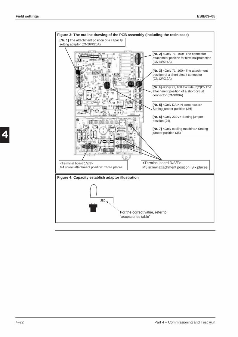
Field settings ESIE03–05
3
1
4
5
[Nr. 1] The attachment position of a capacity setting adaptor (CN26/X26A)
Figure 3: The outline drawing of the PCB assembly (including the resin case)
[Nr. 4] <Only 71, 100 exclude R(Y)P> The attachment position of a short circuit connector (CN9/X9A)
[Nr. 5] <Only DAIKIN compressor> Setting jumper position (JH)
[Nr. 6] <Only 230V> Setting jumper position (J4)
[Nr. 7] <Only cooling machine> Setting jumper position (J5)
<Terminal board R/S/T>M5 screw attachment position: Six places
<Terminal board 1/2/3>M4 screw attachment position: Three places
[Nr. 3] <Only 71, 100> The attachment position of a short circuit connector (CN12/X12A)
[Nr. 2] <Only 71, 100> The connector attachment position for terminal protection (CN14/X14A)
Figure 4: Capacity establish adaptor illustration
J80
For the correct value, refer to “accessories table”
4–22 Part 4 – Commissioning and Test Run

ESIE03–05 Field settings
3
4
5
1
2.11 The Field Setting LevelsIntroduction The three field setting levels are:
Inspection level
Monitoring level
Maintenance mode settings.
The inspection level The inspection level is the highest level of the three field setting levels. You can change the views in the inspection level by pressing the INSPECTION/TEST button.
The flow chart below explains the different windows of the inspection level.
Normal display
Last occurredmalfunction
Indoor model andsize
System
Test
Push INSPECTION/TEST button
Push INSPECTION/TEST button
Push INSPECTION/TEST button
Push INSPECTION/TEST button
PushINSPECTION/TEST
button
See possiblesystem settings.
Part 4 – Commissioning and Test Run 4–23

Field settings ESIE03–05
3
1
4
5
Possible system settings
The table below contains the possible system settings, which are displayed on the remote controller if the TEST button is pushed twice shortly.
Changing the mode settings
To enter the monitoring level and to change the maintenance mode settings, proceed as follows:
SizeSoftware
Type
Settings Display Settings Display
35 35
5
FHYCP FC
45 45 FHYP HC
60 63 FAYP AC
71 71 FHYKP EC
100 100 FHYBP JC
125 125 FUYP 3C
200 200 FDYP UC
250 250 —
Step Action
1 Hold down the INSPECTION/TEST button for at least 4 s to enter the field setting mode.
2 Hold down the INSPECTION/TEST button for at least 4 s to enter the maintenance mode.
3 Press the TEMPERATURE CONTROL buttons as many times as needed to select the mode No. you want.
4 Press the TIMER SELECTION button as many times as needed to select the unit No. you want.
5 Carry out the settings for modes 44 and 45. See “Maintenance Mode Settings” further in this section.
6 Press the CONFIRMATION button to confirm the settings of modes 44 and 45.
7 Press the INSPECTION/TEST button to return to the normal operating mode.
4–24 Part 4 – Commissioning and Test Run

ESIE03–05 Field settings
3
4
5
1
Maintenance Mode SettingsThe table below describes the maintenance mode settings.
Mode No. Function Content and operation method Example of the remote controller display
40History error codes
Display malfunction history
The history No. can be changed with the pro-gramming time button.
41Thermistor data display
Select the display thermistor with the pro-gramming time button.
Thermistor:0. Remote control thermistor1. Suction thermistor2. Heat exchanger thermistor.
43 Forced fan ON Turns the fan ON for each unit individually.
44Individualsetting
Sets fan speed and air flow direction for each unit individually when using group control.
Settings are made using the “air flow direc-tion adjust” and “fan speed adjust” buttons. Confirmation by the confirmation button is required.
45Unit No. change
Changes unit No.
Set the unit No. after changing with the pro-gramming time buttons.Confirmation by the confirmation button is required.
Past error code
Malfunction history
* “00” displayed for 3 and subsequent
0: Newest
2: Oldest
-
CODE SETTING
Unit No.
Unit No.
Thermistor
Temperature
SETTING
Unit No.
SETTING
Unit No.
SETTING
Fan speed
1: Low3: High
Air flow direction
CODE
Unit No.
SETTINGCODE
Field set No
No after change
Part 4 – Commissioning and Test Run 4–25

Field settings ESIE03–05
3
1
4
5
2.12 Overview of the Field Settings: RYEP71-125L
Jumpers The table below contains the jumper field settings.
DIP switches The table below contains the DIP switch field settings.
Jumper Label on PCB Function Applicable units See page
J1 Thermo CTR Change thermostat OFF control indoor unit RYEP71-125L 4–28
J3 Thermo CTR2 Change thermostat ON control indoor unit 4–28
DIP switch
Function Details Applicable units See page
DS1-1 Emergency ON/OFF Switch emergency operation out-door unit ON
RYEP71-125L 4–26
DS1-2 Cool / Heat Select emergency cooling / heating operation on outdoor unit
4–29
DS1-3 Increase possibility to start defrost
Changes the accumulated operation time from 3 hours to 40 minutes in order to advance the defrosting operation.
Increases the temperature conditions for defrost activation with 4K.
4–29
DS1-4 Mode B Avoid risk of liquid back to the compressor
At factory setting (switch = OFF), the E.V. will open at the maximum (480 pulses) for a limited time (1 or 2 minutes) before closing to 100 pulses.
When changing this setting, the time of opening the E.V. at maximum opening is reduced to 30 seconds.
Stops the compressor at defrost start and stop
4–29
DS2-1 Not applicable — RYEP71-125L 4–29
DS2-2 Not applicable — 4–29
DS2-3 Change Freeze-up conditions Freeze-up start / stop decided by indoor unit.(Unit will restart when evaporator temperature reached 7˚C for 10 minutes)
4–30
DS2-4 Change Freeze-up conditions Setting for low humidity applica-tions. (Unit will restart when evapo-rator temperature reached 7˚C for 3 minutes)
4–30
4–26 Part 4 – Commissioning and Test Run

ESIE03–05 Field settings
3
4
5
1
BS The table below contains the BS field setting.Pump down Pump down is preferably carried out with the indoor unit set to “fan only” in order to avoid compressor restart with closed stop valves after finishing the previous pump down operation (close stop valves, turn OFF the power supply).
If accidentally, the power was switched back ON, the unit will automatically restart with closed stop valves, which may result in a possible compressor breakdown.
BS Label on PCB Function Applicable units Details
BS Pump down / forced defrost
Cooling/fan only: Pump down (see further in this section)
Heating: Forced defrosting
RYEP71-125L —
Part 4 – Commissioning and Test Run 4–27

Field settings ESIE03–05
3
1
4
5
2.13 Jumpers
Input and output The table below describes the input and the output of the jumpers.
J1 The function of jumper J1 is to reduce the possibility of thermostat OFF (reduce ON/OFF cycle compr.).
J3 The function of jumper J3 is to increase the differential for thermo ON.
Item Description
Input ∆Tr Cooling ∆Tr = Tr - Ts Tr = indoor unit suction air temp.
Ts = temp. set by the remote controllerHeating ∆Tr = Ts - Tr
Output Magnetic switch compressor K1M
Factory setting (closed state) Field setting (open state)
Thermostat goes into OFF-state when
∆Tr ≤ 0.0˚C
Thermostat goes into OFF-state when
-0.5˚C < ∆Tr ≤ 0.0˚C for 3 min, or
-1.5˚C < ∆Tr ≤ -0.5˚C for 1 min, or
∆Tr ≤ -1.5˚C
+1.0
0.0
∆TrInput: ∆Tr
Output: K1M
ON
OFF
≥ 3 min
-1.5
+1.0
0.0-0.5
∆Tr
Input: ∆Tr
Output: K1M
ON
OFF
≥ 3 min
∆Tr ≤ 0.0˚C and ≥ 3 min
∆Tr ≤ -0.5˚C and ≥ 1 min
∆Tr ≤ -1.5˚C no delay
Factory setting (closed state) Field setting (open state)
Thermostat goes into ON-state when
∆Tr ≥ 1.0˚C
Thermostat goes into ON-state when
∆Tr ≥ 4.5˚C
+1.0
∆Tr
0.0
Input: ∆Tr
Output: K1M
ON
OFF
Pump down
+4.5
∆Tr
0.0
Input: ∆Tr
Output: K1M
ON
OFF
Pump down
4–28 Part 4 – Commissioning and Test Run

ESIE03–05 Field settings
3
4
5
1
2.14 DIP switch DS1DS1-3: Defrost starting condition
The table below describes the DIP switch.
DS1-4: Mode B
The table below describes the DIP switch.
Setting Illustration Function
Factory setting OFF For temperature settings at defrosting, see page 2–40.
Accumulated operation time for defrost activation = 3 h.
Field setting ON Increases the temp. conditions for defrost activation with 4˚C.
Changes the accumulated operation time from 3 h to 40 min in order to advance the defrosting operation.
1 2 3 4
1 2 3 4
Setting Illustration Function
Factory setting OFF At the start-up of the defrost operation, the E.V. opens at the max. (480 pulses) for a limited time (1 or 2 min), before closing to 100 pulses.
Field setting ON Changes the following in order to avoid liquid back to the compressor:
Changes the limited time of E.V. opening at max. (480 pulses) from 1 or 2 min to 30 s.
Stops the compressor at defrost start and stop.
1 2 3 4
1 2 3 4
Part 4 – Commissioning and Test Run 4–29

Field settings ESIE03–05
3
1
4
5
2.15 DIP switch DS2
DS2-3: Freeze 1
The table below describes the DIP switch.
DS2-4: Freeze 2
The table below describes the DIP switch.
Setting Illustration Function
Factory setting OFF Enables the “intelligent” control function.
See page 2–29.
Field setting ON Disables the “intelligent” control function. Freeze-up start/stop decided by indoor unit. (Unit will restart when evaporator temperature reached 7˚C for 10 minutes.)
To be used in combination with EKRPER only!
1 2 3 4
1 2 3 4
Setting Illustration Function
Factory setting OFF Normal operation.
Field setting ON Countermeasure for low humidity applications.
1 2 3 4
1 2 3 4
4–30 Part 4 – Commissioning and Test Run

ESIE03–05 Field settings
3
4
5
1
DS2-4:Method and illustrationThe capacity will be increased when the dip switch DS2-4, mounted on the outdoor PCB, is set to ON.
DS2-4:Capacity result at low temperature:
The capacity increases when outdoor temperature drops below 21˚C as indicated on table below:
*This is a relative comparisson to indicate an increase of 50 to 100% capacity with the dipswitch ON.
Note See page 2–29 “Freeze up conditions” for detailed information.
DS2-4: Caution Finally the capacity result will depend on the total condition of the installation site. This is the responsibility of the customer.
There is additional limitation for the relative humidity when operating this switch. Finally it will depend on the total condition of the installation site and is responsibility of the customer.
Evaluation is necessary for each installation site by a proffesional responsible installer.
Only use the switch for capacity increase in the area indicated on the graph of page 2–32.
Do not set the switch in combination with the option EKRPER, this is only for use of Daikin indoor units.
Dip switch OFF (Factory setting) Dip switch ON
Capacity low temperature 100%* 150~200%
Reason for limitation:
When operating with switch ON, there will be a change of freeze protection control see table on next page. By this there will be some risk of:
Ice building up at indoor heat exchanger.
Water blown off from the unit into the room
Part 4 – Commissioning and Test Run 4–31

Field settings ESIE03–05
3
1
4
5
4–32 Part 4 – Commissioning and Test Run

ESIE03–05 Test Run and Operation Data
1
Part 43
4
5
3 Test Run and Operation Data
Introduction This chapter contains the following information:
General operation data
Operation ranges.
Overview This chapter contains the following topics:
Topic See page
3.1–General Operation Data 4–34
3.2–RYEP71L7V1, RYEP71L7W1, RYEP100L7V1, RYEP100L7W1 and RYEP125L7W1
4–36
Part 4 – Commissioning and Test Run 4–33

Test Run and Operation Data ESIE03–05
3
1
4
5
3.1 General Operation Data
During cooling mode and dry keep
The operating conditions must be as follows:
The operation values are guidelines in the operation range:
LP: 3.0~6.5 barg (low pressure)
HP: 12.0~28.0 barg (high pressure)
Td: 60~95˚C (discharge pipe temperature compressor)
Ts: -2~15˚C (suction pipe temperature compressor)
∆Ti: 8~16˚C (indoor temperature difference air return – air outlet ).
During heating mode
The operating conditions must be as follows:
The operation values are guidelines in the operation range:
LP: 1.8~6.4 barg (low pressure)
HP: 13.0~28.0 barg (high pressure)
Td: 55~95˚C (discharge pipe temperature compressor)
Ts: -15~10˚C (suction pipe temperature compressor)
∆Ti: 12~32˚C (indoor temperature difference air return – air outlet ).
Items Operating modes If the operation is out this range...
Outdoor temp. h/p: -5 to +46˚CDB A safety device may stop the operation.
Condensation may occur on the indoor unit and start dripping.
Indoor temp. +12 to +28˚CWB
Indoor humidity 80%
Items Operating modes If the operation is out this range...
Outdoor temp. -10 to +15˚CWB A safety device may stop the operation.
Indoor temp. +15 to +27˚CDB
4–34 Part 4 – Commissioning and Test Run

ESIE03–05 Test Run and Operation Data
3
4
5
1
Correlation of Air- Conditioner's Operation Status and Pressure / Running CurrentWhat happens in comparison to normal values is summarized in the table below. (Measured from 15 ~ 20 minutes or more after operation starts.)
When Cooling
When Heating
Note *1. Water in the refrigerant freezes inside the capillary tube or expansion valve, and is basically the same phenomenon as pump down.
*2. Dirt in the refrigerant clogs filters inside the piping, and is basically the same phenomenon as pump down.
*3. Pressure differential between high and low pressure becomes slight.
Air-Conditioner Status Low Pressure High Pressure Running Current
Air Filter Fouling Lower Lower Lower
Short Circuit of Indoor Unit Inlet/ Outlet Air
Lower Lower Lower
Outdoor Unit Fin Fouling Higher Higher Higher
Short Circuit of Outdoor Unit Inlet/Outlet Air
Higher Higher Higher
Air Mixed in Refrigerant Higher Higher Higher
Water Mixed in Refrigerant *1 Lower Lower Lower
Dirt Mixed in Refrigerant *2 Lower Lower Lower
Lack of Refrigerant (Gas) Lower Lower Lower
Unsatisfactory Compression *3 Higher Lower Lower
Air-Conditioner Status Low Pressure High Pressure Running Current
Air Filter Fouling Higher Higher Higher
Short Circuit of Indoor Unit Inlet/ Outlet Air
Higher Higher Higher
Outdoor Unit Fin Fouling Lower Lower Lower
Short Circuit of Outdoor Unit Inlet/Outlet Air
Lower Lower Lower
Air Mixed in Refrigerant Higher Higher Higher
Water Mixed in Refrigerant *1 Lower Lower Lower
Dirt Mixed in Refrigerant *2 Lower Lower Lower
Lack of Refrigerant (Gas) Lower Lower Lower
Unsatisfactory Compression *3 Higher Lower Lower
Part 4 – Commissioning and Test Run 4–35

Test Run and Operation Data ESIE03–05
3
1
4
5
3.2 RYEP71L7V1, RYEP71L7W1, RYEP100L7V1, RYEP100L7W1 and RYEP125L7W1
Conditions The illustrations in this section are based on the following conditions:
Equivalent piping length: 7.5 m
Level difference: 0 m
Air flow rate: High.
Operation range: Cooling
The illustration below shows the operation range.
Operation range: Heating
The illustration below shows the operation range.
Outdoor temp. (˚CDB)
Indoor temp. (˚CWB)
Pul
l-dow
n pe
riod
Ope
ratio
n ra
nge
Outdoor temp. (˚CWB)
Indoor temp. (˚CDB)
War
min
g pe
riod
Ope
ratio
n ra
nge
4–36 Part 4 – Commissioning and Test Run

ESIE03–05
4
3
4
55
Part 5Disassembly and
Maintenance
What is in this part? This part contains the following chapters:
Chapter See page
1–Disassembly and Maintenance: Outdoor Units 5–3
Part 5 – Disassembly and Maintenance 5–1

ESIE03–05
3
1
5
5–2 Part 5 – Disassembly and Maintenance

ESIE03–05 Disassembly and Maintenance: Outdoor Units
1
Part 53
55
1 Disassembly and Maintenance: Outdoor Units
1.1 What Is in This Chapter?
Introduction This chapter contains the following information on the outdoor units:
Exploded views
Components.
Overview This chapter contains the following topics:
Topic See page
1.2–RYEP71L7V1 and RYEP71L7W1 5–4
1.3–RYEP100L7V1 and RYEP100L7W1 5–6
1.4–RYEP125L7W1 5–8
Part 5 – Disassembly and Maintenance 5–3

Disassembly and Maintenance: Outdoor Units ESIE03–05
3
1
55
1.2 RYEP71L7V1 and RYEP71L7W1
Exploded view The illustration below shows the exploded view.
5–4 Part 5 – Disassembly and Maintenance

ESIE03–05 Disassembly and Maintenance: Outdoor Units
3
5
1
5
Components The table below contains the components of the exploded view.
No. Component No. Component
1 Compressor (ZR34K3E-TFD) 42 Fan motor capacitor
1 Compressor (ZR34K3E-PFJ) 43 Motor operated valve coil
2 Rubber vibration isolator 44 Thermistor
3 Compress shell sound absorber 45 Thermistor
4 Bolt for compressor 46 Thermistor
5 Nut with washer 47 Capacitor fixing band
6 Compress head sound absorber 48 Comp. motor capacitor
7 Plate finned coil heat exch as 49 Wire clip
8 Liquid receiver assy 50 Compressor cable
9 Flare nut 3/8 50 Compressor cable
10 Flare nut 5/8” 51 Fan propellor
11 Stop valve cap 52 Washer
12 Valve cap 53 Top plate assy
13 Muffler 54 Front plate assy
14 Check valve 55 Front plate (2) assy
15 Valve core 56 Side plate assy
16 Shraeder round dustcap 57 Part. plate assy
17 Low pressure switch 58 Fan motor stand left
18 Gas stop valve assy 59 Fan motor stand right
19 Four way valve body 60 Fan motor stand
20 Filter 61 Fan motor stand (up)
21 Muffler 62 Cover
22 Check valve 63 Piping cover (rear)
23 Check valve 64 Stop valve mounting plate
24 Motor operated valve body 65 Bell mouth assy
25 Solenoid valve body 66 Suction grill
26 T-joint TSS2-2-2 67 Air discharge grill
27 Liquid stop valve assy 68 Handle
28 FI233 Filter 69 Bottom frame assy
29 FI233 Filter 70 Installation leg painted
30 Strainer 71 Bottom tray assy
31 T-joint 72 Cushion top
32 Insulation tube 73 Packing case p/m
33 Discharge pressure regulator 74 Thermistor fixing plate
34 Pipe insulation 75 Single phase AC fan motor
35 Strainer 76 Thermistor mounting spring
36 Elec. comp. mounting assy 77 Thermistor mounting spring
37 PCB assy 78 Coil of 4-way valve
37 PCB assy 79 Insulation material
38 Resin cover assy 80 Insulation tube (gas)
39 Elec. comp. box lower cover 81 Crank case heater
40 Magnetic switch 82 Solenoid valve coil
41 Transformer 83 Stopper
Part 5 – Disassembly and Maintenance 5–5

Disassembly and Maintenance: Outdoor Units ESIE03–05
3
1
55
1.3 RYEP100L7V1 and RYEP100L7W1
Exploded view The illustration below shows the exploded view.
5–6 Part 5 – Disassembly and Maintenance

ESIE03–05 Disassembly and Maintenance: Outdoor Units
3
5
1
5
Components The table below contains the components of the exploded view.
No. Component No. Component
1 Compressor (ZR47K3E-TFD) 42 Motor operated valve coil
1 Compressor (ZR47K3E-PFJ) 43 Thermistor
2 Compress shell sound absorber 44 Thermistor
3 Rubber vibration isolator 45 Thermistor
4 Bolt for compressor 46 Terminal strip
5 Nut with washer 47 Capacitor fixing band
6 Compress head sound absorber 48 Comp. motor capacitor
7 Plate finned coil heat exch as 49 Wire clip
8 Liquid receiver assy 50 Compressor cable
9 Flare nut 3/8 50 Compressor cable
10 Flare nut FNS-6 51 Fan propellor
11 Valve cap 52 Washer
12 Stop valve cap 53 Top plate assy
13 Check valve 54 Front plate assy
14 Valve core 55 Front plate (2) assy
15 Shraeder round dustcap 56 Side plate assy
16 Low pressure switch 57 Part. plate assy
17 Check valve 58 Fan motor stand
18 Check valve 59 Fan motor stand (up)
19 Solenoid valve body 60 Fan motor stand left
20 T-joint TSS2-2-2 61 Fan motor stand right
21 Liquid stop valve assy 62 Suction grill
22 FI233 Filter 63 Packing case P/M
23 Strainer 64 Coil of 4-way valve
24 T-joint 65 Cover
25 Discharge pressure regulator 66 Piping cover (rear)
26 Pipe insulation 67 Stop valve mounting plate
27 Strainer 68 Bell mouth assy
28 Muffler 69 Air discharge grill
29 Gas stop valve assy 70 Handle
30 4-way reversing valve body 71 Bottom frame assy
31 Filter 72 Installation leg painted
32 Muffler 73 Bottom tray assy
33 Motor operated valve body 74 Cushion top
34 Filter 75 Thermistor fixing plate
35 Elec. comp. mounting assy 76 Single phase AC fan motor
36 PCB assy 77 Thermistor mounting spring
36 PCB assy 78 Thermistor mounting spring
37 Resin cover assy 79 Insulation material
38 Elec. comp. box lower cover 80 Insulation tube (gas)
39 Magnetic switch 81 Crank case heater
39 Magnetic switch 82 Solenoid valve coil
40 Transformer 83 Stopper
41 Fan motor capacitor
Part 5 – Disassembly and Maintenance 5–7

Disassembly and Maintenance: Outdoor Units ESIE03–05
3
1
55
1.4 RYEP125L7W1
Exploded view The illustration below shows the exploded view.
5–8 Part 5 – Disassembly and Maintenance

ESIE03–05 Disassembly and Maintenance: Outdoor Units
3
5
1
5
Components The table below contains the components of the exploded view.
No. Component No. Component
1 #7026# Compressor 40 Thermistor
2 Sound insulation (for comp/1) 41 Thermistor
3 Rubber cushion pre-assy 42 Terminal strip
4 Bolt for compressor 43 Wire clip
5 Nut with washer 44 Compressor cable
6 Plate finned coil heat exch as 45 Fan propellor
7 Liquid receiver assy 46 Washer
8 Flare nut 3/8 47 Top plate assy
9 Flare nut FNS-6 48 Front plate assy
10 Valve cap 49 Front plate (2) assy
11 Stop valve cap 50 Side plate assy
12 Check valve 51 Part. plate assy
13 Valve core 52 Fan motor stand
14 Shraeder round dustcap 53 Fan motor stand (up)
15 Low pressure switch 54 Fan motor stand left
16 High pressure switch 55 Fan motor stand right
17 Check valve 56 Suction grill
18 Check valve 57 Packing case p/m
19 Solenoid valve body 58 Coil of 4-way valve
20 T-joint TSS2-2-2 59 Thermal insulation tube
21 Liquid stop valve assy 60 Cover
22 FI233 Filter 61 Piping cover (rear)
23 Strainer 62 Stop valve mounting plate
24 T-joint 63 Bell mouth assy
25 Muffler 64 Air discharge grill
26 Gas stop valve assy 65 Handle
27 4-way reversing valve body 66 Bottom frame assy
28 Filter 67 Installation leg painted
29 Motor operated valve body 68 Bottom tray assy
30 Filter 69 Cushion top
31 Elec. comp. mounting assy 70 Thermistor fixing plate
32 PCB assy 71 Single phase AC fan motor
33 Resin cover assy 72 Single phase AC fan motor
34 Elec. comp. box lower cover 73 Thermistor mounting spring
35 Magnetic switch 74 Thermistor mounting spring
36 Transformer 75 HPS cable
37 Fan motor capacitor 76 Solenoid valve coil
38 Motor operated valve coil 77 Stopper
39 Thermistor
Part 5 – Disassembly and Maintenance 5–9

Disassembly and Maintenance: Outdoor Units ESIE03–05
3
1
55
5–10 Part 5 – Disassembly and Maintenance

ESIE03–05
3
4
5
1Index
Numerics4-way valve control . . . . . . . . . . . . . . . . . . . . . . . . . . . . .. . . . . . . . . . . . . . . . . . . . . . . . . . . . . . . . . . . . k 2–46
AA1 . . . . . . . . . . . . . . . . . . . . . . . . . . . . . . . . . . . . . . . . . .. . . . . . . . . . . . . . . . . . . . . . . . . . . . . . . . . . . . k 3–24A3 . . . . . . . . . . . . . . . . . . . . . . . . . . . . . . . . . . . . . . . . . .. . . . . . . . . . . . . . . . . . . . . . . . . . . . . . . . . . . . k 3–25A6 . . . . . . . . . . . . . . . . . . . . . . . . . . . . . . . . . . . . . . . . . .. . . . . . . . . . . . . . . . . . . . . . . . . . . . . . . . . . . . k 3–27AF . . . . . . . . . . . . . . . . . . . . . . . . . . . . . . . . . . . . . . . . . .. . . . . . . . . . . . . . . . . . . . . . . . . . . . . . . . . . . . k 3–29AJ . . . . . . . . . . . . . . . . . . . . . . . . . . . . . . . . . . . . . . . . . .. . . . . . . . . . . . . . . . . . . . . . . . . . . . . . . . . . . . k 3–31auto-restart function . . . . . . . . . . . . . . . . . . . . . . . . . . . .. . . . . . . . . . . . . . . . . . . . . . . . . . . . . . . . . . . . k 2–21
BBS . . . . . . . . . . . . . . . . . . . . . . . . . . . . . . . . . . . . . . . . . .. . . . . . . . . . . . . . . . . . . . . . . . . . . . . . . . . . . . k 4–27
CC4 . . . . . . . . . . . . . . . . . . . . . . . . . . . . . . . . . . . . . . . . . .. . . . . . . . . . . . . . . . . . . . . . . . . . . . . . . . . . . . k 3–33C9 . . . . . . . . . . . . . . . . . . . . . . . . . . . . . . . . . . . . . . . . . .. . . . . . . . . . . . . . . . . . . . . . . . . . . . . . . . . . . . k 3–33ceiling height . . . . . . . . . . . . . . . . . . . . . . . . . . . . . . . . . .. . . . . . . . . . . . . . . . . . . . . . . . . . . . . . . . . . . . k 4–15centralized group No.
setting . . . . . . . . . . . . . . . . . . . . . . . . . . . . . . . . . .. . . . . . . . . . . . . . . . . . . . . . . . . . . . . . . . . . . . k 4–18changing
field settings, wired remote controller . . . . . . . . . .. . . . . . . . . . . . . . . . . . . . . . . . . . . . . . . . . . . . k 4–11field settings, wireless remote controller . . . . . . . .. . . . . . . . . . . . . . . . . . . . . . . . . . . . . . . . . . . . k 4–12maintenance mode settings . . . . . . . . . . . . . . . . .. . . . . . . . . . . . . . . . . . . . . . . . . . . . . . . . . . . . k 4–24
checkingclogged points . . . . . . . . . . . . . . . . . . . . . . . . . . . .. . . . . . . . . . . . . . . . . . . . . . . . . . . . . . . . . . . . k 3–85discharge pressure . . . . . . . . . . . . . . . . . . . . . . . .. . . . . . . . . . . . . . . . . . . . . . . . . . . . . . . . . . . . k 3–78expansion valve . . . . . . . . . . . . . . . . . . . . . . . . . .. . . . . . . . . . . . . . . . . . . . . . . . . . . . . . . . . . . . k 3–79installation condition . . . . . . . . . . . . . . . . . . . . . . .. . . . . . . . . . . . . . . . . . . . . . . . . . . . . . . . . . . . k 3–77PCB’s Hall IC . . . . . . . . . . . . . . . . . . . . . . . . . . . .. . . . . . . . . . . . . . . . . . . . . . . . . . . . . . . . . . . . k 3–74power supply wave form . . . . . . . . . . . . . . . . . . . .. . . . . . . . . . . . . . . . . . . . . . . . . . . . . . . . . . . . k 3–75refrigerant system . . . . . . . . . . . . . . . . . . . . . . . . .. . . . . . . . . . . . . . . . . . . . . . . . . . . . . . . . . . . . k 3–76test run checks . . . . . . . . . . . . . . . . . . . . . . . . . . .. . . . . . . . . . . . . . . . . . . . . . . . . . . . . . . . . . . . . k 4–4thermistors . . . . . . . . . . . . . . . . . . . . . . . . . . . . . .. . . . . . . . . . . . . . . . . . . . . . . . . . . . . . . . . . . . k 3–80
CJ . . . . . . . . . . . . . . . . . . . . . . . . . . . . . . . . . . . . . . . . . .. . . . . . . . . . . . . . . . . . . . . . . . . . . . . . . . . . . . k 3–35components
exploded views, outdoor units. . . . . . . . . . . . . . . .. . . . . . . . . . . . . . . . . . . . . . . . . . . . . . . . . . . . . k 5–3functional diagrams. . . . . . . . . . . . . . . . . . . . . . . .. . . . . . . . . . . . . . . . . . . . . . . . . . . . . . . . . . . . k 1–17general outline, indoor units . . . . . . . . . . . . . . . . .. . . . . . . . . . . . . . . . . . . . . . . . . . . . . . . . . . . . k 1–13general outline, outdoor units . . . . . . . . . . . . . . . .. . . . . . . . . . . . . . . . . . . . . . . . . . . . . . . . . . . . . k 1–3PCB layout . . . . . . . . . . . . . . . . . . . . . . . . . . . . . .. . . . . . . . . . . . . . . . . . . . . . . . . . . . . . . . . . . . k 1–31switch box layout. . . . . . . . . . . . . . . . . . . . . . . . . .. . . . . . . . . . . . . . . . . . . . . . . . . . . . . . . . . . . . k 1–23wired remote controller . . . . . . . . . . . . . . . . . . . . .. . . . . . . . . . . . . . . . . . . . . . . . . . . . . . . . . . . . k 4–10wireless remote controller . . . . . . . . . . . . . . . . . . .. . . . . . . . . . . . . . . . . . . . . . . . . . . . . . . . . . . . k 4–12wiring diagrams, outdoor units . . . . . . . . . . . . . . .. . . . . . . . . . . . . . . . . . . . . . . . . . . . . . . . . . . . k 1–27
condensation avoidance control . . . . . . . . . . . . . . . . . . .. . . . . . . . . . . . . . . . . . . . . . . . . . . . . . . . . . . . k 2–38control modes . . . . . . . . . . . . . . . . . . . . . . . . . . . . . . . . .. . . . . . . . . . . . . . . . . . . . . . . . . . . . . . . . . . . . . k 2–6
Index i

ESIE03–05
3
1
4
5
Ddefrost control . . . . . . . . . . . . . . . . . . . . . . . . . . . . . . . . .. . . . . . . . . . . . . . . . . . . . . . . . . . . . . . . . . . . . k 2–40diameters, pipe connections . . . . . . . . . . . . . . . . . . . . . .. . . . . . . . . . . . . . . . . . . . . . . . . . . . . . . . . . . . k 1–17dimensions
indoor units . . . . . . . . . . . . . . . . . . . . . . . . . . . . . .. . . . . . . . . . . . . . . . . . . . . . . . . . . . . . . . . . . . k 1–13outdoor units . . . . . . . . . . . . . . . . . . . . . . . . . . . . .. . . . . . . . . . . . . . . . . . . . . . . . . . . . . . . . . . . . . k 1–3
DIP switches . . . . . . . . . . . . . . . . . . . . . . . . . . . . . . . . . .. . . . . . . . . . . . . . . . . . . . . . . . . . . . . . . . . . . . k 4–26discharge pipe temperature control . . . . . . . . . . . . . . . . .. . . . . . . . . . . . . . . . . . . . . . . . . . . . . . . . . . . . k 2–16display malfunction . . . . . . . . . . . . . . . . . . . . . . . . . . . . .. . . . . . . . . . . . . . . . . . . . . . . . . . . . . . . . . . . . k 3–12draft avoidance control
1. . . . . . . . . . . . . . . . . . . . . . . . . . . . . . . . . . . . . . .. . . . . . . . . . . . . . . . . . . . . . . . . . . . . . . . . . . . k 2–432. . . . . . . . . . . . . . . . . . . . . . . . . . . . . . . . . . . . . . .. . . . . . . . . . . . . . . . . . . . . . . . . . . . . . . . . . . . k 2–45
drain pump control . . . . . . . . . . . . . . . . . . . . . . . . . . . . . .. . . . . . . . . . . . . . . . . . . . . . . . . . . . . . . . . . . . k 2–18dry keep mode. . . . . . . . . . . . . . . . . . . . . . . . . . . . . . . . .. . . . . . . . . . . . . . . . . . . . . . . . . . . . . . . . . . . . k 2–28DS1 . . . . . . . . . . . . . . . . . . . . . . . . . . . . . . . . . . . . . . . . .. . . . . . . . . . . . . . . . . . . . . . . . . . . . . . . . . . . . k 4–29DS2 . . . . . . . . . . . . . . . . . . . . . . . . . . . . . . . . . . . . . . . . .. . . . . . . . . . . . . . . . . . . . . . . . . . . . . . . . . . . . k 4–30
EE0 . . . . . . . . . . . . . . . . . . . . . . . . . . . . . . . . . . . . . . . . . .. . . . . . . . . . . . . . . . . . . . . . . . . . . . . . . . . . . . k 3–38E1 . . . . . . . . . . . . . . . . . . . . . . . . . . . . . . . . . . . . . . . . . .. . . . . . . . . . . . . . . . . . . . . . . . . . . . . . . . . . . . k 3–43E3 . . . . . . . . . . . . . . . . . . . . . . . . . . . . . . . . . . . . . . . . . .. . . . . . . . . . . . . . . . . . . . . . . . . . . . . . . . . . . . k 3–44E4 . . . . . . . . . . . . . . . . . . . . . . . . . . . . . . . . . . . . . . . . . .. . . . . . . . . . . . . . . . . . . . . . . . . . . . . . . . . . . . k 3–46E6 . . . . . . . . . . . . . . . . . . . . . . . . . . . . . . . . . . . . . . . . . .. . . . . . . . . . . . . . . . . . . . . . . . . . . . . . . . . . . . k 3–48E9 . . . . . . . . . . . . . . . . . . . . . . . . . . . . . . . . . . . . . . . . . .. . . . . . . . . . . . . . . . . . . . . . . . . . . . . . . . . . . . k 3–50EEPROM . . . . . . . . . . . . . . . . . . . . . . . . . . . . . . . . . . . . .. . . . . . . . . . . . . . . . . . . . . . . . . . . . . . . . . . . . k 3–24electrical specifications . . . . . . . . . . . . . . . . . . . . . . . . . .. . . . . . . . . . . . . . . . . . . . . . . . . . . . . . . . . . . . k 1–15emergency operation
general. . . . . . . . . . . . . . . . . . . . . . . . . . . . . . . . . .. . . . . . . . . . . . . . . . . . . . . . . . . . . . . . . . . . . . . k 2–7error codes
indoor malfunctions overview . . . . . . . . . . . . . . . .. . . . . . . . . . . . . . . . . . . . . . . . . . . . . . . . . . . . k 3–14outdoor malfunctions overview . . . . . . . . . . . . . . .. . . . . . . . . . . . . . . . . . . . . . . . . . . . . . . . . . . . k 3–15system malfunctions overview. . . . . . . . . . . . . . . .. . . . . . . . . . . . . . . . . . . . . . . . . . . . . . . . . . . . k 3–16
evaluationabnormal high pressure. . . . . . . . . . . . . . . . . . . . .. . . . . . . . . . . . . . . . . . . . . . . . . . . . . . . . . . . . k 3–83abnormal low pressure . . . . . . . . . . . . . . . . . . . . .. . . . . . . . . . . . . . . . . . . . . . . . . . . . . . . . . . . . k 3–84
expansion valve control . . . . . . . . . . . . . . . . . . . . . . . . . .. . . . . . . . . . . . . . . . . . . . . . . . . . . . . . . . . . . . k 2–24exploded views
outdoor units . . . . . . . . . . . . . . . . . . . . . . . . . . . . .. . . . . . . . . . . . . . . . . . . . . . . . . . . . . . . . . . . . . k 5–3
FF3. . . . . . . . . . . . . . . . . . . . . . . . . . . . . . . . . . . . . . . . . . .. . . . . . . . . . . . . . . . . . . . . . . . . . . . . . . . . . . . k 3–52F6. . . . . . . . . . . . . . . . . . . . . . . . . . . . . . . . . . . . . . . . . . .. . . . . . . . . . . . . . . . . . . . . . . . . . . . . . . . . . . . k 3–58factory settings
indoor units . . . . . . . . . . . . . . . . . . . . . . . . . . . . . .. . . . . . . . . . . . . . . . . . . . . . . . . . . . . . . . . . . . k 4–14fan and flap operations . . . . . . . . . . . . . . . . . . . . . . . . . .. . . . . . . . . . . . . . . . . . . . . . . . . . . . . . . . . . . . k 2–20fan control
normal, cooling mode . . . . . . . . . . . . . . . . . . . . . .. . . . . . . . . . . . . . . . . . . . . . . . . . . . . . . . . . . . k 2–35normal, heating mode . . . . . . . . . . . . . . . . . . . . . .. . . . . . . . . . . . . . . . . . . . . . . . . . . . . . . . . . . . k 2–48starting, cooling or dry keep mode . . . . . . . . . . . .. . . . . . . . . . . . . . . . . . . . . . . . . . . . . . . . . . . . k 2–34starting, heating mode. . . . . . . . . . . . . . . . . . . . . .. . . . . . . . . . . . . . . . . . . . . . . . . . . . . . . . . . . . k 2–47
field settingsBS . . . . . . . . . . . . . . . . . . . . . . . . . . . . . . . . . . . . .. . . . . . . . . . . . . . . . . . . . . . . . . . . . . . . . . . . . k 4–27DIP switches overview. . . . . . . . . . . . . . . . . . . . . .. . . . . . . . . . . . . . . . . . . . . . . . . . . . . . . . . . . . k 4–26jumpers overview. . . . . . . . . . . . . . . . . . . . . . . . . .. . . . . . . . . . . . . . . . . . . . . . . . . . . . . . . . . . . . k 4–26levels . . . . . . . . . . . . . . . . . . . . . . . . . . . . . . . . . . .. . . . . . . . . . . . . . . . . . . . . . . . . . . . . . . . . . . . k 4–23overview indoor units. . . . . . . . . . . . . . . . . . . . . . .. . . . . . . . . . . . . . . . . . . . . . . . . . . . . . . . . . . . k 4–13
filter counter . . . . . . . . . . . . . . . . . . . . . . . . . . . . . . . . . . .. . . . . . . . . . . . . . . . . . . . . . . . . . . . . . . . . . . . k 4–16forced operating mode
general. . . . . . . . . . . . . . . . . . . . . . . . . . . . . . . . . .. . . . . . . . . . . . . . . . . . . . . . . . . . . . . . . . . . . . . k 2–7forced thermostat OFF. . . . . . . . . . . . . . . . . . . . . . . . . . .. . . . . . . . . . . . . . . . . . . . . . . . . . . . . . . . . . . . k 2–13freeze-up function . . . . . . . . . . . . . . . . . . . . . . . . . . . . . .. . . . . . . . . . . . . . . . . . . . . . . . . . . . . . . . . . . . k 2–29
ii Index

ESIE03–05
3
4
5
1
functional diagrams . . . . . . . . . . . . . . . . . . . . . . . . . . . . .. . . . . . . . . . . . . . . . . . . . . . . . . . . . . . . . . . . . k 1–17Ggas shortage function . . . . . . . . . . . . . . . . . . . . . . . . . . .. . . . . . . . . . . . . . . . . . . . . . . . . . . . . . . . . . . . k 2–17
HH3 . . . . . . . . . . . . . . . . . . . . . . . . . . . . . . . . . . . . . . . . . .. . . . . . . . . . . . . . . . . . . . . . . . . . . . . . . . . . . . k 3–54H9 . . . . . . . . . . . . . . . . . . . . . . . . . . . . . . . . . . . . . . . . . .. . . . . . . . . . . . . . . . . . . . . . . . . . . . . . . . . . . . k 3–55high pressure protection control . . . . . . . . . . . . . . . . . . .. . . . . . . . . . . . . . . . . . . . . . . . . . . . . . . . . . . . k 2–37HPS and LPS function. . . . . . . . . . . . . . . . . . . . . . . . . . .. . . . . . . . . . . . . . . . . . . . . . . . . . . . . . . . . . . . k 2–14
Iidentification function. . . . . . . . . . . . . . . . . . . . . . . . . . . .. . . . . . . . . . . . . . . . . . . . . . . . . . . . . . . . . . . . k 2–10installation space
indoor units . . . . . . . . . . . . . . . . . . . . . . . . . . . . . .. . . . . . . . . . . . . . . . . . . . . . . . . . . . . . . . . . . . k 1–13outdoor units . . . . . . . . . . . . . . . . . . . . . . . . . . . . .. . . . . . . . . . . . . . . . . . . . . . . . . . . . . . . . . . . . . k 1–3
JJ1. . . . . . . . . . . . . . . . . . . . . . . . . . . . . . . . . . . . . . . . . . .. . . . . . . . . . . . . . . . . . . . . . . . . . . . . . . . . . . . k 4–28J2. . . . . . . . . . . . . . . . . . . . . . . . . . . . . . . . . . . . . . . . . . .. . . . . . . . . . . . . . . . . . . . . . . . . . . . . . . . . . . . k 3–59J3. . . . . . . . . . . . . . . . . . . . . . . . . . . . . . . . . . . . . . . . . . .. . . . . . . . . . . . . . . . . . . . . . . . . . . . . . . . . . . . k 4–28J3. . . . . . . . . . . . . . . . . . . . . . . . . . . . . . . . . . . . . . . . . . .. . . . . . . . . . . . . . . . . . . . . . . . . . . . . . . . . . . . k 3–56J6. . . . . . . . . . . . . . . . . . . . . . . . . . . . . . . . . . . . . . . . . . .. . . . . . . . . . . . . . . . . . . . . . . . . . . . . . . . . . . . k 3–57jumpers . . . . . . . . . . . . . . . . . . . . . . . . . . . . . . . . . . . . . .. . . . . . . . . . . . . . . . . . . . . . . . . . . . . . . . . . . . k 4–28
LLEDs
troubleshooting with indoor unit LEDs and remote controller . . . . . . . . . . . . . . . . . . . . . . . . . . . . k 3–14troubleshooting with outdoor unit LEDs and remote controller, outdoor unit malfunctions . . . . . k 3–15troubleshooting with outdoor unit LEDs and remote controller, system malfunctions. . . . . . . . . k 3–16
locatingexploded views, outdoor units. . . . . . . . . . . . . . . .. . . . . . . . . . . . . . . . . . . . . . . . . . . . . . . . . . . . . k 5–3functional diagrams. . . . . . . . . . . . . . . . . . . . . . . .. . . . . . . . . . . . . . . . . . . . . . . . . . . . . . . . . . . . k 1–17general outline, indoor units . . . . . . . . . . . . . . . . .. . . . . . . . . . . . . . . . . . . . . . . . . . . . . . . . . . . . k 1–13general outline, outdoor units . . . . . . . . . . . . . . . .. . . . . . . . . . . . . . . . . . . . . . . . . . . . . . . . . . . . . k 1–3PCB layout . . . . . . . . . . . . . . . . . . . . . . . . . . . . . .. . . . . . . . . . . . . . . . . . . . . . . . . . . . . . . . . . . . k 1–31switch box layout. . . . . . . . . . . . . . . . . . . . . . . . . .. . . . . . . . . . . . . . . . . . . . . . . . . . . . . . . . . . . . k 1–23thermistors . . . . . . . . . . . . . . . . . . . . . . . . . . . . . .. . . . . . . . . . . . . . . . . . . . . . . . . . . . . . . . . . . . . k 2–4wired remote controller components . . . . . . . . . . .. . . . . . . . . . . . . . . . . . . . . . . . . . . . . . . . . . . . k 4–10wireless remote controller components. . . . . . . . .. . . . . . . . . . . . . . . . . . . . . . . . . . . . . . . . . . . . k 4–12wiring diagrams, outdoor units . . . . . . . . . . . . . . .. . . . . . . . . . . . . . . . . . . . . . . . . . . . . . . . . . . . k 1–27
low-pressure switch. . . . . . . . . . . . . . . . . . . . . . . . . . . . .. . . . . . . . . . . . . . . . . . . . . . . . . . . . . . . k 3–21, 3–22
MMAIN . . . . . . . . . . . . . . . . . . . . . . . . . . . . . . . . . . . . . . . .. . . . . . . . . . . . . . . . . . . . . . . . . . . . . . . . . . . . k 4–17malfunctions
indoor error codes overview . . . . . . . . . . . . . . . . .. . . . . . . . . . . . . . . . . . . . . . . . . . . . . . . . . . . . k 3–14outdoor error codes overview . . . . . . . . . . . . . . . .. . . . . . . . . . . . . . . . . . . . . . . . . . . . . . . . . . . . k 3–15system error codes overview . . . . . . . . . . . . . . . .. . . . . . . . . . . . . . . . . . . . . . . . . . . . . . . . . . . . k 3–16
Nnoise . . . . . . . . . . . . . . . . . . . . . . . . . . . . . . . . . . . . . . . .. . . . . . . . . . . . . . . . . . . . . . . . . . . . . . . . . . . . . k 3–5
Index iii

ESIE03–05
3
1
4
5
Ooperating modes . . . . . . . . . . . . . . . . . . . . . . . . . . . . . . .. . . . . . . . . . . . . . . . . . . . . . . . . . . . . . . . . . . . . k 2–6operation data . . . . . . . . . . . . . . . . . . . . . . . . . . . . . . . . .. . . . . . . . . . . . . . . . . . . . . . . . . . . . . . . . . . . . k 4–34operation range . . . . . . . . . . . . . . . . . . . . . . . . . . . . . . . .. . . . . . . . . . . . . . . . . . . . . . . . . . . . . . . . . . . . k 4–33options . . . . . . . . . . . . . . . . . . . . . . . . . . . . . . . . . . . . . . .. . . . . . . . . . . . . . . . . . . . . . . . . . . . . . . . . . . . k 1–15outlook
indoor units . . . . . . . . . . . . . . . . . . . . . . . . . . . . . .. . . . . . . . . . . . . . . . . . . . . . . . . . . . . . . . . . . . k 1–13outdoor units . . . . . . . . . . . . . . . . . . . . . . . . . . . . .. . . . . . . . . . . . . . . . . . . . . . . . . . . . . . . . . . . . . k 1–3
overcurrent protection function . . . . . . . . . . . . . . . . . . . .. . . . . . . . . . . . . . . . . . . . . . . . . . . . . . . . . . . . k 2–23
PPCBs . . . . . . . . . . . . . . . . . . . . . . . . . . . . . . . . . . . . . . . .. . . . . . . . . . . . . . . . . . . . . . . . . . . . . . . . . . . . k 1–31PJ. . . . . . . . . . . . . . . . . . . . . . . . . . . . . . . . . . . . . . . . . . .. . . . . . . . . . . . . . . . . . . . . . . . . . . . . . . . . . . . k 3–61
RR1T . . . . . . . . . . . . . . . . . . . . . . . . . . . . . . . . . . . . . . . . .. . . . . . . . . . . . . . . . . . . . . . . . . . . . . . . . . . . . k 3–81R2T . . . . . . . . . . . . . . . . . . . . . . . . . . . . . . . . . . . . . . . . .. . . . . . . . . . . . . . . . . . . . . . . . . . . . . . . . . . . . k 3–81R3T . . . . . . . . . . . . . . . . . . . . . . . . . . . . . . . . . . . . . . . . .. . . . . . . . . . . . . . . . . . . . . . . . . . . . . . . . . . . . k 3–82remote controller
display malfunction . . . . . . . . . . . . . . . . . . . . . . . .. . . . . . . . . . . . . . . . . . . . . . . . . . . . . . . . . . . . k 3–12setting address for receiver of wireless remote controller. . . . . . . . . . . . . . . . . . . . . . . . . . . . . . . . k 4–5setting address for wireless remote controller . . .. . . . . . . . . . . . . . . . . . . . . . . . . . . . . . . . . . . . . k 4–6thermostat, using conditions . . . . . . . . . . . . . . . . .. . . . . . . . . . . . . . . . . . . . . . . . . . . . . . . . . . . . k 2–22
remote controller . . . . . . . . . . . . . . . . . . . . . . . . . . . . . . .. . . . . . . . . . . . . . . . . . . . . . . . . . . . . . . . . . . . . k 3–6reverse phase protector. . . . . . . . . . . . . . . . . . . . . . . . . .. . . . . . . . . . . . . . . . . . . . . . . . . . . . . . . . . . . . k 3–20
Ssafety devices
low-pressure switch . . . . . . . . . . . . . . . . . . . . . . . .. . . . . . . . . . . . . . . . . . . . . . . . . . . . . . k 3–21, 3–22overview indoor units. . . . . . . . . . . . . . . . . . . . . . .. . . . . . . . . . . . . . . . . . . . . . . . . . . . . . . . . . . . k 3–17overview outdoor units. . . . . . . . . . . . . . . . . . . . . .. . . . . . . . . . . . . . . . . . . . . . . . . . . . . . . . . . . . k 3–18reverse phase protector. . . . . . . . . . . . . . . . . . . . .. . . . . . . . . . . . . . . . . . . . . . . . . . . . . . . . . . . . k 3–20thermal protector fan motor . . . . . . . . . . . . . . . . . .. . . . . . . . . . . . . . . . . . . . . . . . . . . . . . . . . . . . k 3–19
self-diagnosisremote controller . . . . . . . . . . . . . . . . . . . . . . . . . .. . . . . . . . . . . . . . . . . . . . . . . . . . . . . . . . . . . . . k 3–6wired remote controller . . . . . . . . . . . . . . . . . . . . .. . . . . . . . . . . . . . . . . . . . . . . . . . . . . . . . . . . . k 3–11
service spaceindoor units . . . . . . . . . . . . . . . . . . . . . . . . . . . . . .. . . . . . . . . . . . . . . . . . . . . . . . . . . . . . . . . . . . k 1–13outdoor units . . . . . . . . . . . . . . . . . . . . . . . . . . . . .. . . . . . . . . . . . . . . . . . . . . . . . . . . . . . . . . . . . . k 1–3
settingaddress for receiver of wireless remote controller.. . . . . . . . . . . . . . . . . . . . . . . . . . . . . . . . . . . . . k 4–5address for wireless remote controller. . . . . . . . . .. . . . . . . . . . . . . . . . . . . . . . . . . . . . . . . . . . . . . k 4–6ceiling height . . . . . . . . . . . . . . . . . . . . . . . . . . . . .. . . . . . . . . . . . . . . . . . . . . . . . . . . . . . . . . . . . k 4–15centralized group No. . . . . . . . . . . . . . . . . . . . . . .. . . . . . . . . . . . . . . . . . . . . . . . . . . . . . . . . . . . k 4–18field settings, wired remote controller . . . . . . . . . .. . . . . . . . . . . . . . . . . . . . . . . . . . . . . . . . . . . . k 4–11field settings, wireless remote controller . . . . . . . .. . . . . . . . . . . . . . . . . . . . . . . . . . . . . . . . . . . . k 4–12filter counter. . . . . . . . . . . . . . . . . . . . . . . . . . . . . .. . . . . . . . . . . . . . . . . . . . . . . . . . . . . . . . . . . . k 4–16MAIN/SUB when using two remote controllers . . .. . . . . . . . . . . . . . . . . . . . . . . . . . . . . . . . . . . . k 4–17
iv Index

ESIE03–05
3
4
5
1
settingsBS . . . . . . . . . . . . . . . . . . . . . . . . . . . . . . . . . . . . .. . . . . . . . . . . . . . . . . . . . . . . . . . . . . . . . . . . . k 4–27ceiling height . . . . . . . . . . . . . . . . . . . . . . . . . . . . .. . . . . . . . . . . . . . . . . . . . . . . . . . . . . . . . . . . . k 4–15changing maintenance mode . . . . . . . . . . . . . . . .. . . . . . . . . . . . . . . . . . . . . . . . . . . . . . . . . . . . k 4–24DIP switches . . . . . . . . . . . . . . . . . . . . . . . . . . . . .. . . . . . . . . . . . . . . . . . . . . . . . . . . . . . . . . . . . k 4–26factory overview . . . . . . . . . . . . . . . . . . . . . . . . . .. . . . . . . . . . . . . . . . . . . . . . . . . . . . . . . . . . . . k 4–14field overview . . . . . . . . . . . . . . . . . . . . . . . . . . . .. . . . . . . . . . . . . . . . . . . . . . . . . . . . . . . . . . . . k 4–13filter counter . . . . . . . . . . . . . . . . . . . . . . . . . . . . .. . . . . . . . . . . . . . . . . . . . . . . . . . . . . . . . . . . . k 4–16jumpers overview . . . . . . . . . . . . . . . . . . . . . . . . .. . . . . . . . . . . . . . . . . . . . . . . . . . . . . . . . . . . . k 4–26MAIN/SUB. . . . . . . . . . . . . . . . . . . . . . . . . . . . . . .. . . . . . . . . . . . . . . . . . . . . . . . . . . . . . . . . . . . k 4–17maintenance mode . . . . . . . . . . . . . . . . . . . . . . . .. . . . . . . . . . . . . . . . . . . . . . . . . . . . . . . . . . . . k 4–25possible system settings . . . . . . . . . . . . . . . . . . . .. . . . . . . . . . . . . . . . . . . . . . . . . . . . . . . . . . . . k 4–24
simulated operation function . . . . . . . . . . . . . . . . . . . . . .. . . . . . . . . . . . . . . . . . . . . . . . . . . . . . . . . . . . k 2–15specifications. . . . . . . . . . . . . . . . . . . . . . . . . . . . . . . . . .. . . . . . . . . . . . . . . . . . . . . . . . . . . . . . . . . . . . k 1–15SUB. . . . . . . . . . . . . . . . . . . . . . . . . . . . . . . . . . . . . . . . .. . . . . . . . . . . . . . . . . . . . . . . . . . . . . . . . . . . . k 4–17switch boxes . . . . . . . . . . . . . . . . . . . . . . . . . . . . . . . . . .. . . . . . . . . . . . . . . . . . . . . . . . . . . . . . . . . . . . k 1–23
Ttechnical specifications . . . . . . . . . . . . . . . . . . . . . . . . . .. . . . . . . . . . . . . . . . . . . . . . . . . . . . . . . . . . . . k 1–15test run
checks . . . . . . . . . . . . . . . . . . . . . . . . . . . . . . . . . .. . . . . . . . . . . . . . . . . . . . . . . . . . . . . . . . . . . . . k 4–4thermal protector fan motor . . . . . . . . . . . . . . . . . . . . . . .. . . . . . . . . . . . . . . . . . . . . . . . . . . . . . . . . . . . k 3–19thermistors
checking . . . . . . . . . . . . . . . . . . . . . . . . . . . . . . . .. . . . . . . . . . . . . . . . . . . . . . . . . . . . . . . . . . . . k 3–80functions . . . . . . . . . . . . . . . . . . . . . . . . . . . . . . . .. . . . . . . . . . . . . . . . . . . . . . . . . . . . . . . . . . . . . k 2–4locating . . . . . . . . . . . . . . . . . . . . . . . . . . . . . . . . .. . . . . . . . . . . . . . . . . . . . . . . . . . . . . . . . . . . . . k 2–4R1T and R2T. . . . . . . . . . . . . . . . . . . . . . . . . . . . .. . . . . . . . . . . . . . . . . . . . . . . . . . . . . . . . . . . . k 3–81R3T . . . . . . . . . . . . . . . . . . . . . . . . . . . . . . . . . . . .. . . . . . . . . . . . . . . . . . . . . . . . . . . . . . . . . . . . k 3–82
thermostat control . . . . . . . . . . . . . . . . . . . . . . . . . . . . . .. . . . . . . . . . . . . . . . . . . . . . . . . . . . . . . . . . . . k 2–11
UU0 . . . . . . . . . . . . . . . . . . . . . . . . . . . . . . . . . . . . . . . . . .. . . . . . . . . . . . . . . . . . . . . . . . . . . . . . . . . . . . k 3–64U1 . . . . . . . . . . . . . . . . . . . . . . . . . . . . . . . . . . . . . . . . . .. . . . . . . . . . . . . . . . . . . . . . . . . . . . . . . . . . . . k 3–65U4 . . . . . . . . . . . . . . . . . . . . . . . . . . . . . . . . . . . . . . . . . .. . . . . . . . . . . . . . . . . . . . . . . . . . . . . . . . . . . . k 3–67U5 . . . . . . . . . . . . . . . . . . . . . . . . . . . . . . . . . . . . . . . . . .. . . . . . . . . . . . . . . . . . . . . . . . . . . . . . . . . . . . k 3–69U8 . . . . . . . . . . . . . . . . . . . . . . . . . . . . . . . . . . . . . . . . . .. . . . . . . . . . . . . . . . . . . . . . . . . . . . . . . . . . . . k 3–70UA . . . . . . . . . . . . . . . . . . . . . . . . . . . . . . . . . . . . . . . . . .. . . . . . . . . . . . . . . . . . . . . . . . . . . . . . . . . . . . k 3–71UF . . . . . . . . . . . . . . . . . . . . . . . . . . . . . . . . . . . . . . . . . .. . . . . . . . . . . . . . . . . . . . . . . . . . . . . . . . . . . . k 3–67
Vvibrations . . . . . . . . . . . . . . . . . . . . . . . . . . . . . . . . . . . . .. . . . . . . . . . . . . . . . . . . . . . . . . . . . . . . . . . . . . k 3–5
Wwired remote controller . . . . . . . . . . . . . . . . . . . . . . . . . .. . . . . . . . . . . . . . . . . . . . . . . . . . . . . . . . . . . . k 3–11wiring diagrams
outdoor units . . . . . . . . . . . . . . . . . . . . . . . . . . . . .. . . . . . . . . . . . . . . . . . . . . . . . . . . . . . . . . . . . k 1–27
Index v

ESIE03–05
3
1
4
5
vi Index